WO2021186873A1 - 眼鏡レンズ - Google Patents
眼鏡レンズ Download PDFInfo
- Publication number
- WO2021186873A1 WO2021186873A1 PCT/JP2021/001346 JP2021001346W WO2021186873A1 WO 2021186873 A1 WO2021186873 A1 WO 2021186873A1 JP 2021001346 W JP2021001346 W JP 2021001346W WO 2021186873 A1 WO2021186873 A1 WO 2021186873A1
- Authority
- WO
- WIPO (PCT)
- Prior art keywords
- spectacle lens
- regions
- light
- predetermined position
- segment
- Prior art date
Links
- 230000004075 alteration Effects 0.000 claims abstract description 30
- 230000005043 peripheral vision Effects 0.000 claims description 33
- 238000011156 evaluation Methods 0.000 claims description 23
- 230000009471 action Effects 0.000 claims description 7
- 210000001747 pupil Anatomy 0.000 claims description 5
- 230000001154 acute effect Effects 0.000 claims description 3
- 230000000007 visual effect Effects 0.000 description 61
- 210000001525 retina Anatomy 0.000 description 29
- 230000002093 peripheral effect Effects 0.000 description 27
- 210000005252 bulbus oculi Anatomy 0.000 description 25
- 239000000463 material Substances 0.000 description 24
- 230000006870 function Effects 0.000 description 21
- 230000000694 effects Effects 0.000 description 18
- 230000004379 myopia Effects 0.000 description 17
- 208000001491 myopia Diseases 0.000 description 17
- 208000014733 refractive error Diseases 0.000 description 13
- 230000000052 comparative effect Effects 0.000 description 11
- 230000003287 optical effect Effects 0.000 description 9
- 210000001508 eye Anatomy 0.000 description 8
- 238000004088 simulation Methods 0.000 description 8
- 230000004515 progressive myopia Effects 0.000 description 7
- 238000010586 diagram Methods 0.000 description 6
- 238000009826 distribution Methods 0.000 description 6
- 238000000034 method Methods 0.000 description 6
- 229920005989 resin Polymers 0.000 description 6
- 239000011347 resin Substances 0.000 description 6
- 238000000465 moulding Methods 0.000 description 5
- 239000011248 coating agent Substances 0.000 description 4
- 238000000576 coating method Methods 0.000 description 4
- 206010020675 Hypermetropia Diseases 0.000 description 3
- 230000004907 flux Effects 0.000 description 3
- 201000006318 hyperopia Diseases 0.000 description 3
- 230000004305 hyperopia Effects 0.000 description 3
- 230000001771 impaired effect Effects 0.000 description 3
- 230000015572 biosynthetic process Effects 0.000 description 2
- 238000005266 casting Methods 0.000 description 2
- 230000004438 eyesight Effects 0.000 description 2
- 238000009472 formulation Methods 0.000 description 2
- 210000000873 fovea centralis Anatomy 0.000 description 2
- 238000004519 manufacturing process Methods 0.000 description 2
- 239000000203 mixture Substances 0.000 description 2
- 238000006116 polymerization reaction Methods 0.000 description 2
- 230000001629 suppression Effects 0.000 description 2
- 125000003903 2-propenyl group Chemical group [H]C([*])([H])C([H])=C([H])[H] 0.000 description 1
- 229910018072 Al 2 O 3 Inorganic materials 0.000 description 1
- 241000282412 Homo Species 0.000 description 1
- NIXOWILDQLNWCW-UHFFFAOYSA-N acrylic acid group Chemical group C(C=C)(=O)O NIXOWILDQLNWCW-UHFFFAOYSA-N 0.000 description 1
- 201000009310 astigmatism Diseases 0.000 description 1
- 238000004364 calculation method Methods 0.000 description 1
- 230000008859 change Effects 0.000 description 1
- 239000003795 chemical substances by application Substances 0.000 description 1
- 230000023077 detection of light stimulus Effects 0.000 description 1
- 239000011521 glass Substances 0.000 description 1
- 238000001746 injection moulding Methods 0.000 description 1
- 239000007788 liquid Substances 0.000 description 1
- 230000005499 meniscus Effects 0.000 description 1
- 230000004048 modification Effects 0.000 description 1
- 238000012986 modification Methods 0.000 description 1
- 230000001537 neural effect Effects 0.000 description 1
- 230000008447 perception Effects 0.000 description 1
- 210000000608 photoreceptor cell Anatomy 0.000 description 1
- 230000009467 reduction Effects 0.000 description 1
- 230000004044 response Effects 0.000 description 1
- 229920005992 thermoplastic resin Polymers 0.000 description 1
- 229920001187 thermosetting polymer Polymers 0.000 description 1
- 238000007740 vapor deposition Methods 0.000 description 1
Images


Classifications
-
- G—PHYSICS
- G02—OPTICS
- G02C—SPECTACLES; SUNGLASSES OR GOGGLES INSOFAR AS THEY HAVE THE SAME FEATURES AS SPECTACLES; CONTACT LENSES
- G02C7/00—Optical parts
- G02C7/02—Lenses; Lens systems ; Methods of designing lenses
- G02C7/022—Ophthalmic lenses having special refractive features achieved by special materials or material structures
-
- G—PHYSICS
- G02—OPTICS
- G02C—SPECTACLES; SUNGLASSES OR GOGGLES INSOFAR AS THEY HAVE THE SAME FEATURES AS SPECTACLES; CONTACT LENSES
- G02C7/00—Optical parts
- G02C7/02—Lenses; Lens systems ; Methods of designing lenses
- G02C7/06—Lenses; Lens systems ; Methods of designing lenses bifocal; multifocal ; progressive
-
- G—PHYSICS
- G02—OPTICS
- G02C—SPECTACLES; SUNGLASSES OR GOGGLES INSOFAR AS THEY HAVE THE SAME FEATURES AS SPECTACLES; CONTACT LENSES
- G02C7/00—Optical parts
- G02C7/02—Lenses; Lens systems ; Methods of designing lenses
- G02C7/024—Methods of designing ophthalmic lenses
-
- G—PHYSICS
- G02—OPTICS
- G02C—SPECTACLES; SUNGLASSES OR GOGGLES INSOFAR AS THEY HAVE THE SAME FEATURES AS SPECTACLES; CONTACT LENSES
- G02C2202/00—Generic optical aspects applicable to one or more of the subgroups of G02C7/00
- G02C2202/24—Myopia progression prevention
Definitions
- the present invention relates to a spectacle lens.
- the myopia population has been on the rise.
- myopia it has been reported that when a part of the light incident on the eyeball is imaged in the back of the retina, the progress is promoted, and when the image is formed in the foreground, it is suppressed.
- the transmitted light has a first region formed so that the transmitted light is focused at a predetermined position (for example, a position on the retina of the eyeball) and the transmitted light.
- a predetermined position for example, a position on the retina of the eyeball
- Some have a second region formed to focus at a position different from a predetermined position (eg, a position other than on the retina of the eyeball).
- a convex surface as a first region, which is a surface on the object side, in which a plurality of convex regions having a curved surface different from the convex surface and projecting from the convex surface are formed as a second region.
- the light beam incident from the surface on the object side and emitted from the surface on the eyeball side basically focuses on the retina of the wearer, but the light ray passing through the convex region portion. Focus on the object closer to the object than on the retina. In other words, an approach is taken to reduce the light that forms the image in the back of the retina and increase the light that forms the image in the foreground, which suppresses the progression of myopia.
- the lens structure different between the corresponding part of the central visual field and the corresponding part of the peripheral visual field.
- the shape, power, and the like of the second region are different between the corresponding portion of the central visual field and the corresponding portion of the peripheral visual field, or a strong curvature of field is given to one portion.
- the lens structure is partially different, the surface of the entire lens becomes non-uniform and the appearance is impaired.
- the eyeball is rotated, the correspondence between the distribution of the lens structure and the line of sight changes, so that a sufficient effect cannot always be obtained.
- An object of the present invention is to provide a technique that enables a spectacle lens to exert an effect of suppressing the progression of refractive error even in peripheral vision.
- the present invention has been devised to achieve the above object.
- the first aspect of the present invention is A first region formed so that the transmitted light focuses at a predetermined position in the eye, and a plurality of second regions formed so that the transmitted light focuses at a position defocused from the predetermined position.
- a spectacle lens with The plurality of second regions are spectacle lenses having negative spherical aberration.
- a second aspect of the present invention is The first aspect, in which the plurality of second regions have the negative spherical aberration so that the light perceived in peripheral vision is recognized as false focusing at a position other than the predetermined position. It is a spectacle lens described in.
- a third aspect of the present invention is The first or first spherical aberration in the plurality of second regions is given so that the evaluation value of the transmitted light in the peripheral vision using the Gabor function has a maximum value at a position other than the predetermined position.
- the spectacle lens according to the second aspect is The spectacle lens according to the second aspect.
- a fourth aspect of the present invention is The first to first spherical aberrations in the plurality of second regions are given so that the evaluation value of the transmitted light in the peripheral vision using the Gabor function has the maximum value at a position other than the predetermined position.
- the spectacle lens according to any one aspect of 3.
- a fifth aspect of the present invention is The plurality of second regions have the negative spherical aberration, so that the light rays passing through the outermost side of the second region and the light rays passing from the outermost side to the inside by 10% of the radius of the second region.
- the spectacle lens according to any one of the first to fourth aspects, wherein the intersecting position is configured to be between the predetermined position and the position defocused from the predetermined position.
- a sixth aspect of the present invention is The spectacle lens according to any one of the first to fifth aspects, wherein the plurality of second regions are formed in an aspherical shape such that the curvature becomes smaller as the distance from the center of the second region increases.
- a seventh aspect of the present invention is At least three of the plurality of second regions are arranged within the range of the pupil diameter through which the transmitted light passes, and the figure connecting the reference points of the three second regions becomes an acute triangle.
- the spectacle lens according to any one of the first to sixth aspects, wherein the size and the arrangement interval of the plurality of second regions are formed.
- the eighth aspect of the present invention is The plurality of second regions are the spectacle lenses according to any one of the first to seventh aspects, which are arranged in six directions.
- a ninth aspect of the present invention is The plurality of second regions are composed of a multi-layer structure.
- the innermost layer in the multilayer structure is a layer having an action of imparting a defocus frequency, and is a layer having a function of imparting a defocus frequency.
- the layer outside the spectacle lens is the spectacle lens according to any one of the first to eighth aspects, which is a layer having an action of imparting negative spherical aberration.
- the spectacle lens exert an effect of suppressing the progression of refractive error even in peripheral vision.
- FIG. 1 is a schematic cross-sectional view (No. 1) showing a path of light transmitted through the spectacle lens shown in FIG.
- FIG. 2 is a schematic cross-sectional view (No. 2) showing a path of light transmitted through the spectacle lens shown in FIG.
- It is a schematic cross-sectional view which shows the path of the main ray of the light incident on each segment in the case of the central view and the peripheral view.
- It is an enlarged view which shows the shape and curvature of the convex region in the spectacle lens shown in FIG.
- It is explanatory drawing which shows the simulation image when the light which passes through the convex region shown in FIG. 5 is perceived by the central visual field of an eyeball.
- the spectacle lens given as an example in the present embodiment is a refractive error progress suppressing lens that suppresses the progress of refractive error in the eyes of the spectacle wearer.
- the refractive error progression suppressing lens has a first region having a first refractive power based on a formulation for correcting the refractive error of the eye and a refractive power different from the first refractive power, and can detect the progression of the refractive error of the eye. It is configured to have a second region having a function of focusing on a position other than the refraction of the eye so as to suppress it.
- Refractive error progression suppressing lenses include myopia progression suppressing lenses that suppress the progression of myopia and hyperopia progression suppressing lenses that suppress the progression of hyperopia.
- myopia progression suppressing lens will be taken as an example.
- FIG. 1 is a front view showing an example of an spectacle lens in the present embodiment.
- 2 and 3 are schematic cross-sectional views showing the path of light passing through the spectacle lens shown in FIG.
- the spectacle lens 1 has a surface on the object side and a surface on the eyeball side.
- the "object-side surface” is a surface located on the object side when the spectacles provided with the spectacle lens 1 are worn by the wearer.
- the "eyeball-side surface” is the opposite, that is, the surface located on the eyeball side when the spectacles provided with the spectacle lens 1 are worn by the wearer.
- the surface on the object side is a convex surface
- the surface on the eyeball side is a concave surface. That is, the spectacle lens 1 is a meniscus lens.
- the spectacle lens 1 is configured to include a lens base material.
- the lens base material is formed of, for example, a thermosetting resin material such as thiourethane, allyl, acrylic, or epithio.
- a thermosetting resin material such as thiourethane, allyl, acrylic, or epithio.
- the resin material constituting the lens base material another resin material capable of obtaining a desired refractive index may be selected.
- the lens base material may be made of inorganic glass instead of the resin material.
- a coating is formed on at least one of the object-side surface and the eyeball-side surface of the lens base material.
- the film include a hard coat film and an antireflection film (AR film), but in addition to these, other films may be formed.
- the hard coat film is formed by using, for example, a thermoplastic resin or a UV curable resin.
- the hard coat film can be formed by immersing the lens base material in the hard coat liquid, or by using a spin coat or the like. By covering with such a hard coat film, the durability of the spectacle lens 1 can be improved.
- the antireflection film is formed by, for example, forming an antireflection agent such as ZrO 2 , MgF 2 , Al 2 O 3 by vacuum vapor deposition. By covering with such an antireflection film, the visibility of the image through the spectacle lens 1 can be improved.
- a plurality of convex regions are formed on the object-side surface (convex surface) of the lens base material so as to project from the surface toward the object side.
- Each convex region is formed by a curved surface having a curvature different from the surface of the lens base material on the object side.
- a coating film such as a hard coat film or an antireflection film
- a plurality of convex regions are formed on the surface of the coating film as well as the convex region of the lens base material. It will be formed.
- the surface (convex surface) of the spectacle lens 1 on the object side is formed so as to project from the surface toward the object side depending on the convex region of the lens base material and the thickness of the coating film covering the convex region.
- a plurality of convex regions 6 are arranged.
- a case where a plurality of convex regions 6 are arranged on the surface on the object side is illustrated, but the present invention is not necessarily limited to this, and at least one of the surface on the object side and the surface on the eyeball side is used. It suffices if it is arranged on the surface of.
- the plurality of convex regions 6 are regularly arranged on the surface of the spectacle lens 1.
- the plurality of convex regions 6 are partially arranged in the vicinity of the center of the lens, but the present invention is not limited to this, and if the convex regions 6 are regularly arranged, the present invention is not limited to this. It may be arranged on the entire surface of the lens, or may be arranged in a circumferential shape so as to surround the center of the lens.
- the plurality of convex regions 6 are arranged in an independent island shape (that is, in a state of being separated from each other without being adjacent to each other). That is, in the present embodiment, each of the convex regions 6 is arranged discretely (that is, in a state where they are not continuous and are scattered apart). However, here, the case where all of the convex regions 6 are independent islands is illustrated, but the present invention is not necessarily limited to this, and includes those in which the outer edges of adjacent regions are connected or in contact with each other. Each convex region 6 may be arranged as described above.
- the light incident on the object-side surface 3 of the region (hereinafter referred to as “base region”) in which the convex region 6 is not formed is emitted from the eyeball-side surface 4.
- the focus is on the retina 20A of the eyeball 20. That is, in principle, the light rays transmitted through the spectacle lens 1 are focused on the retina 20A of the spectacle wearer.
- the curvature of the base region of the spectacle lens 1 is set according to the prescription of the spectacle wearer so as to focus on the retina 20A which is a predetermined position A.
- the base region of the spectacle lens 1 has a first refractive power based on a formulation that corrects the refractive error of the eye of the spectacle wearer, so that the transmitted light of the lens is focused on the retina 20A at the predetermined position A. It will function as a "first region” formed in.
- the term "focusing” as used herein means that light is focused and imaged, but it does not necessarily have to be an aberration-free image, and has spherical aberration or astigmatism. It may be.
- the term "focus” means a point recognized as a point that has a maximum value for vision.
- the convex region 6 converges the light emitted from the surface 4 on the eyeball side to the position B closer to the object side than the predetermined position A.
- the convergence position B in response to each of a plurality of elevated regions 6, the position B 1, B 2, B 3, present as ⁇ ⁇ ⁇ B N. Therefore, each of the plurality of convex regions 6 functions as a "second region" formed so that the lens transmitted light focuses on the defocused position B from the predetermined position A.
- the convex region 6 that functions as the second region is also referred to as a “segment”.
- the spectacle lens 1 emits light rays incident from the surface 3 on the object side from the surface 4 on the eyeball side and converges them at a predetermined position A, while in the portion where the segment 6 is arranged, the spectacle lens 1 emits light rays.
- the light beam is converged to the position B (B 1 , B 2 , B 3 , ... BN ) closer to the object side than the predetermined position A. That is, the spectacle lens 1 has a light ray converging function to the position B closer to the object side, which is different from the light ray converging function for realizing the prescription of the spectacle wearer.
- the spectacle lens 1 can exert an effect of suppressing the progress of refractive error such as myopia of the spectacle wearer (hereinafter referred to as "myopia suppressing effect").
- FIG. 4 is a schematic cross-sectional view showing the path of the main ray of light incident on each segment in the case of central vision and peripheral vision.
- the light reaching the peripheral visual field 20B is incident on the spectacle lens 1 at an angle with respect to the light reaching the central visual field 20C.
- the peripheral visual field 20B has a lower spatial resolution than the central visual field 20C. Specifically, in the photoreceptor cells of the peripheral visual field 20B, the resolution is only about 10 to 20% of that of the central visual field 20C. Therefore, in the peripheral visual field 20B, the optical stimulus used as a clue for finding the focal position may be perceived differently from the case of the central visual field 20C.
- the peripheral visual field 20B may not detect it. That is, since the light stimulus used as a clue to find the focal position in the peripheral visual field 20B is different from that in the central visual field 20C, the light transmitted through the segment 6 of the spectacle lens 1 is at the position B closer to the object side than on the retina 20A. Focusing may not be perceived, and as a result, the effect of suppressing the progression of myopia may not be exerted.
- FIG. 5 is an enlarged view showing the shape and curvature of the segment 6 in the spectacle lens 1.
- FIG. 5 focusing on the region C in which the segments as shown in FIG. 5 are arranged in six directions, how the light transmitted through each segment 6 in the region C is perceived will be described.
- FIG. 6 is an explanatory diagram showing a simulation image when the light transmitted through the segment 6 of the spectacle lens 1 is perceived by the central visual field 20C of the eyeball 20.
- the predetermined position A on the retina 20A is set to "0D (diopter)"
- the segment 6 is focused at the position B closer to the object side by "3.4D” than the predetermined position A.
- the results obtained by simulation of how the light transmitted through the segment 6 is perceived in the central field of view 20C at a plurality of locations from 3.4D to 0D for the spectacle lens 1 in which the is formed are shown. There is. As shown in FIG.
- the light transmitted through each segment 6 is a white circle in the figure showing the perceived state of light at the position B (that is, the position of + 3.4D). It can be seen that the diameter of the figure is minimized and the light is perceived as being most focused (see arrow D shown in FIG. 6).
- FIG. 7 is an explanatory diagram showing a simulation image when the light transmitted through the segment 6 of the spectacle lens 1 is perceived by the peripheral visual field 20B of the eyeball 20.
- the simulation results at a plurality of locations between the predetermined position A (0D) and the position B (+ 3.4D) closer to the object side than the predetermined position A (0D) are shown as in the case of the central visual field 20C described above. ..
- the most focused feeling is felt at the position B (that is, the position of + 3.4D). No. That is, it can be seen that the light transmitted through each segment 6 is not perceived individually, but is perceived as one light by combining them, and is perceived as being blurred as a whole.
- the perception mode of light differs between the central visual field 20C and the peripheral visual field 20B due to the difference in resolution. Therefore, even if the segment 6 is formed so as to exert a myopia suppressing effect on the central visual field 20C, it is not always possible to exert a myopia suppressing effect even in peripheral vision.
- the lens structure of the spectacle lens 1 different between the corresponding portion of the central visual field 20C and the corresponding portion of the peripheral visual field 20B.
- the shape, power, etc. of the segment 6 may be different between the corresponding portion of the central visual field 20C and the corresponding portion of the peripheral visual field 20B, or a strong curvature of field may be given to one portion.
- the lens structure is partially different, the surface of the entire lens becomes non-uniform and the appearance is impaired. Further, when the eyeball is rotated, the correspondence between the distribution of the lens structure and the line of sight changes, so that a sufficient effect cannot always be obtained.
- the lens structure different between the corresponding portion of the central visual field 20C and the corresponding portion of the peripheral visual field 20B. Further, it is not preferable that the effect of suppressing myopia on the central visual field 20C is impaired by considering the peripheral vision.
- the light is perceived as being blurred as a whole due to the difference in resolution from the central visual field 20C. That is, unlike the case of the central visual field 20C, the most focused light is not felt at the position B (that is, the position of + 3.4D). However, even if the light is not felt most at position B, it is felt at least at a position closer to the object side than at position A (that is, the position of 0D) (see, for example, arrow E shown in FIG. 7). If it is perceived (that is, if the diameter of the white circle figure in the figure showing the perceived state of light is minimized), it is considered that the effect of suppressing myopia can be exerted to no small extent.
- peripheral vision in order to make the light focused at least at a position closer to the object side than the position A, it is sufficient to use the overlap of blurred images due to the low resolution spatial resolution in the peripheral visual field 20B. That is, in peripheral vision, the light transmitted through each segment 6 is perceived as a blurred image due to the low resolution, but if the light energy increases due to the overlapping portion of the blurred images, it is as if the condensing point is at the position of the overlapping portion. Can be perceived as if there is.
- using the overlap of the blurred images to make them perceive as a pseudo-focusing point other than the optical focal position is simply referred to as "pseudo-focusing".
- each segment is negative so that the light energy at the edge of the blurred image of each segment is higher than that at the center of the blurred image. It suffices to have spherical aberration characteristics.
- the inventor of the present application can exert the effect of suppressing the progression of refractive error even in peripheral vision having low resolution spatial resolution, so that the light perceived in peripheral vision is at a desired position (that is, retina 20A).
- a desired position that is, retina 20A.
- Spherical aberration refers to a phenomenon in which the focusing position differs in the optical axis direction according to the distance from the center of each segment 6.
- the focusing position of the light ray passing through the central portion of the segment 6 in the eye is closer to the spectacle lens 1 than the focusing position of the light ray passing through the peripheral portion in the eye.
- it is called having "negative spherical aberration".
- each segment 6 has a negative spherical aberration, the light perceived in peripheral vision can be recognized as false focusing at a position other than the focal position A on the retina 20A. ..
- negative spherical aberration In order to give negative spherical aberration to each segment 6, one method is to change the convex shape of the segment 6 to an aspherical shape. Specifically, negative spherical aberration can be given by setting the aspherical shape so that the curvature of the convex surface becomes smaller as the distance from the center of the segment 6 increases.
- the spectacle lens 1 preferably includes a plurality of segments 6 in the pupil. Specifically, at least three of the plurality of segments 6 are arranged within the range of the pupil diameter through which the transmitted light passes, and the figure connecting each reference point of the three segments 6 is an acute triangle. It is preferable that the size and the arrangement interval of each segment 6 are formed.
- the reference point of the segment 6 means a point that serves as a reference for specifying the position where the segment 6 is arranged. For example, when the segment 6 has a circular shape in a plan view, the center point of the segment 6 can be a reference point.
- the plurality of segments 6 are arranged in a hexagonal arrangement (particularly, a hexagonal close-packed arrangement).
- each segment 6 causes false light collection can be verified (evaluated) by, for example, the method described below.
- the human visual field recognizes images by an action similar to the Gabor transform (Reference: J. Daugman, “Entropy reduction and decorrelation in visual coding by oriented neural receptive fields”, Trans. On Biomedical Engineering, Vol.36 , No.1, pp. 107-114 (1989).). Following this, it is possible to verify (evaluate) to some extent how light is perceived in the human visual field by the evaluation value using the Gabor function shown in the following equation (1). it is conceivable that.
- x is the horizontal coordinate on the retina and y is the vertical coordinate on the retina, both of which are in mm.
- the Gabor function in the x direction is illustrated, but the Gabor function in the y direction or the intermediate direction may be used.
- the Gabor function shown in the above equation (1) is convoluted into a geometrical optics spot (not a spot considering the spatial resolution of the human field of view), and the maximum of the convoluted result is obtained.
- the value may be a Gabor coefficient (that is, an evaluation value using the Gabor function), and the evaluation value may be used for evaluation of whether or not false convolution has occurred.
- the horizontal axis is the distance (defocus amount, unit: diopter) between the predetermined position A on the retina and the position B where each segment 6 is focused
- the vertical axis is Gabor. It is conceivable to create by taking a coefficient (evaluation value using Gabor function, unit: dimensionless quantity).
- the maximum value is more preferably the maximum value.
- the maximum value does not necessarily have to be the maximum value, and if it is a maximum value having a sufficient magnitude, it is recognized as false light collection even if it is not the maximum value.
- the maximum value may have a value larger than the intermediate value between the maximum value and the minimum value.
- each segment 6 is 0.8 mm
- the frequency P 3.4D given to each segment 6.
- the spectacle lens 1 in which the plurality of segments 6 are arranged is formed so as to be.
- FIG. 8 is an explanatory diagram showing the shape of the segment of the spectacle lens according to the embodiment.
- the cross-sectional shape of the segment 6 in the spectacle lens 1 according to the embodiment is shown by a solid line.
- the lens base material is molded by a known molding method such as casting polymerization.
- a lens base material having a convex region on at least one surface can be obtained by molding by casting polymerization using a molding mold having a molding surface provided with a plurality of concave portions.
- a molding mold in which a plurality of recesses are formed may be used so as to match the above-mentioned use.
- a film such as a hard coat film or an antireflection film is formed on the surface of the lens base material, if necessary.
- the film can be formed by using the known film forming method described above.
- the spectacle lens 1 according to the embodiment can be obtained by the manufacturing method of such a procedure.
- FIG. 9 is an explanatory diagram showing the curvature distribution of the segment of the spectacle lens according to the embodiment.
- the curvature distribution of the segment 6 that is, the curvature distribution of the aspherical shape
- the spectacle lens 1 according to the embodiment is shown by a solid line.
- the curvature near the center of the segment 6 is 5.6 [1 / M], whereas the curvature near the outermost side of the segment 6 is 4. It is as small as 1 [1 / M].
- a negative spherical aberration occurs, and the position where the light ray passing through the outermost side of the segment 6 and the light ray passing through the innermost part of the radius of the segment 6 from the outermost side intersect. Is located 1.7D before the retina 20A, which is the predetermined position A, that is, at an intermediate point between the retina 20A and the focal position B of the segment 6 defocused from the retina 20A.
- FIG. 10 is an explanatory diagram showing an example of a graph of the Gabor coefficient (evaluation value) for the spectacle lens 1 according to the embodiment.
- the horizontal axis is the distance (defocus amount) between the predetermined position A (0D) on the retina and the position B (3.5D) where each segment 6 is focused, and the vertical axis is Gabor.
- the coefficient (evaluation value using the Gabor function) is taken, and the Gabor coefficient (evaluation value) normalized to the value 1 at the best focus position is displayed.
- the Gabor coefficient calculated in consideration of the resolution of the central visual field 20C is shown by a solid line
- the Gabor coefficient calculated in consideration of the resolution of the peripheral visual field 20B is shown. Is indicated by a broken line.
- the Gabor coefficient has a maximum value at the point of 1.7D in the case of the peripheral vision shown by the broken line. That is, in the spectacle lens 1, each segment 6 causes pseudo-condensing at a position other than the predetermined position A on the retina, and as a result, the case of peripheral vision without impairing the myopia suppressing effect on the central visual field 20C. It was confirmed that the effect of suppressing myopia can be exerted.
- FIG. 11 is an explanatory diagram showing an example of a graph of Gabor's coefficient (evaluation value) for the spectacle lens according to the comparative example.
- the horizontal axis, the vertical axis, the solid line, the broken line, and the like are the same as in the graph shown in FIG.
- the Gabor coefficient has a maximum value at the predetermined position A (0D) in the case of the peripheral vision shown by the broken line. That is, in the spectacle lens according to the comparative example, since the segment does not have spherical aberration, false focusing does not occur at a position other than the predetermined position A (0D). Therefore, the spectacle lens according to Comparative Example 1 cannot exert the myopia suppressing effect in the case of peripheral vision.
- FIG. 12 is a side sectional view showing an example of a main part configuration of an spectacle lens according to another embodiment.
- the spectacle lens of the example is configured by imparting an aspherical layer 12 on a base material 11 having a defocus power in order to make the segment into an aspherical shape.
- the base material 11 may serve as a resin lens base material obtained by injection molding
- the aspherical layer 12 may serve as a hard coat film.
- the innermost layer in the multilayer structure (specifically, the layer composed of the base material 11) becomes a layer having an action of imparting the defocus frequency, and the outer layer (specifically, specifically).
- the layer composed of the aspherical layer 12) is a layer having an action of imparting negative spherical aberration.
- the spectacle lens 1 having a configuration having a convex region 6 on the surface 3 on the object side is given as an example, but the present invention can be applied to spectacle lenses having other configurations.
- the present invention includes a first region formed so that the transmitted light is focused at a predetermined position, and a plurality of second regions formed so as to be focused at a defocus position different from the first region.
- the spectacle lens configured with the above can be applied not only to a lens structure having a convex region 6 on the lens surface but also to a lens structure having a smooth lens surface.
- the spectacle lens is a myopia progression suppressing lens
- the present invention can also be applied to a hyperopia progression suppressing lens.
- each convex region (segment) 6 may be arranged so as to cause false focusing in peripheral vision.
Landscapes
- Health & Medical Sciences (AREA)
- Ophthalmology & Optometry (AREA)
- Physics & Mathematics (AREA)
- General Health & Medical Sciences (AREA)
- General Physics & Mathematics (AREA)
- Optics & Photonics (AREA)
- Eyeglasses (AREA)
Abstract
透過光が眼内の所定位置で焦点を結ぶように形成された第1領域と、前記透過光が前記所定位置からデフォーカスした位置で焦点を結ぶように形成された複数の第2領域と、を有する眼鏡レンズであって、前記複数の第2領域が、負の球面収差を有して構成されている。
Description
本発明は、眼鏡レンズに関する。
近年、近視人口が増加の傾向にある。近視については、眼球に入射する光の一部が、網膜の奥に結像すると進行が促進し、手前に結像すると抑制される、と報告されている。
このことから、近視等の屈折異常の進行を抑制する眼鏡レンズとして、透過光が所定位置(例えば、眼球の網膜上の位置)で焦点を結ぶように形成された第1領域と、透過光が所定位置とは異なる位置(例えば、眼球の網膜上以外の位置)で焦点を結ぶように形成された第2領域と、を有するものがある。具体的には、物体側の面である第1領域としての凸面に、当該凸面とは異なる曲面を有して当該凸面から突出する複数の凸状領域が第2領域として形成されたものがある(例えば、特許文献1参照)。
かかる構成の眼鏡レンズによれば、物体側の面から入射し眼球側の面から出射する光線が、原則的には装用者の網膜上に焦点を結ぶが、凸状領域の部分を通過した光線については網膜上よりも物体側寄りの位置で焦点を結ぶ。つまり、網膜の奥に結像する光を減らし、手前に結像する光を増やすアプローチを採っており、これにより近視の進行が抑制されることになる。
眼球に入射する光は、網膜の中心窩を含む中心視野のみならず、中心視野の外側にある周辺視野の部分においても知覚される。
ただし、眼球に入射した光の知覚に際して、中心視野では高空間周波数の明暗パターンの感受性が強い一方で、周辺視野では低空間周波数の明暗パターンの感受性が強いことが知られている。つまり、周辺視野は、中心視野に比べて低解像度の空間分解能となっており、焦点位置を探す手掛かりとされる光刺激が中心視野とは異なって知覚される。
そのため、周辺視においては、第2領域を透過した光が網膜上よりも物体側寄りの位置で焦点を結ぶことが知覚されず、その結果として近視進行を抑制する効果が発揮されないおそれがある。
ただし、眼球に入射した光の知覚に際して、中心視野では高空間周波数の明暗パターンの感受性が強い一方で、周辺視野では低空間周波数の明暗パターンの感受性が強いことが知られている。つまり、周辺視野は、中心視野に比べて低解像度の空間分解能となっており、焦点位置を探す手掛かりとされる光刺激が中心視野とは異なって知覚される。
そのため、周辺視においては、第2領域を透過した光が網膜上よりも物体側寄りの位置で焦点を結ぶことが知覚されず、その結果として近視進行を抑制する効果が発揮されないおそれがある。
この点については、中心視野の対応部分と周辺視野の対応部分とでレンズ構造を相違させて対応することも考えられる。具体的には、中心視野の対応部分と周辺視野の対応部分とで第2領域の形状や度数等を相違させたり、一方の部分に強い像面湾曲を与えたりすることが考えられる。しかしながら、レンズ構造を部分的に相違させると、レンズ全体では表面が不均一となり、見た目が損なわれてしまう。また、眼球の回旋時には、レンズ構造の分布と視線との対応関係が変わるため、必ずしも十分な効果が得られるとは限らない。
本発明は、周辺視においても、眼鏡レンズに屈折異常進行の抑制効果を発揮させることを可能にする技術の提供を目的とする。
本発明は、上記目的を達成するために案出されたものである。
本発明の第1の態様は、
透過光が眼内の所定位置で焦点を結ぶように形成された第1領域と、前記透過光が前記所定位置からデフォーカスした位置で焦点を結ぶように形成された複数の第2領域と、を有する眼鏡レンズであって、
前記複数の第2領域は、負の球面収差を有する
眼鏡レンズである。
本発明の第1の態様は、
透過光が眼内の所定位置で焦点を結ぶように形成された第1領域と、前記透過光が前記所定位置からデフォーカスした位置で焦点を結ぶように形成された複数の第2領域と、を有する眼鏡レンズであって、
前記複数の第2領域は、負の球面収差を有する
眼鏡レンズである。
本発明の第2の態様は、
前記複数の第2領域は、前記負の球面収差を有することで、周辺視において知覚される光が前記所定位置以外の位置における偽集光として認知されるように構成されている
第1の態様に記載の眼鏡レンズである。
前記複数の第2領域は、前記負の球面収差を有することで、周辺視において知覚される光が前記所定位置以外の位置における偽集光として認知されるように構成されている
第1の態様に記載の眼鏡レンズである。
本発明の第3の態様は、
前記周辺視における前記透過光についてのガボール関数を用いた評価値が、前記所定位置以外の位置で極大値を有するように、前記複数の第2領域の球面収差が与えられている
第1または第2の態様に記載の眼鏡レンズである。
前記周辺視における前記透過光についてのガボール関数を用いた評価値が、前記所定位置以外の位置で極大値を有するように、前記複数の第2領域の球面収差が与えられている
第1または第2の態様に記載の眼鏡レンズである。
本発明の第4の態様は、
前記周辺視における前記透過光についてのガボール関数を用いた評価値が、前記所定位置以外の位置で最大値を有するように、前記複数の第2領域の球面収差が与えられている
第1から第3のいずれか1態様に記載の眼鏡レンズである。
前記周辺視における前記透過光についてのガボール関数を用いた評価値が、前記所定位置以外の位置で最大値を有するように、前記複数の第2領域の球面収差が与えられている
第1から第3のいずれか1態様に記載の眼鏡レンズである。
本発明の第5の態様は、
前記複数の第2領域は、前記負の球面収差を有することで、前記第2領域の最外部を通過する光線と前記最外部から前記第2領域の半径の10%だけ内側を通過する光線との交わる位置が、前記所定位置と前記所定位置からデフォーカスした位置との間にあるように構成されている
第1から第4のいずれか1態様に記載の眼鏡レンズである。
前記複数の第2領域は、前記負の球面収差を有することで、前記第2領域の最外部を通過する光線と前記最外部から前記第2領域の半径の10%だけ内側を通過する光線との交わる位置が、前記所定位置と前記所定位置からデフォーカスした位置との間にあるように構成されている
第1から第4のいずれか1態様に記載の眼鏡レンズである。
本発明の第6の態様は、
前記複数の第2領域は、前記第2領域の中心から離れるほど曲率が小さくなるような非球面形状で形成されている
第1から第5のいずれか1態様に記載の眼鏡レンズである。
前記複数の第2領域は、前記第2領域の中心から離れるほど曲率が小さくなるような非球面形状で形成されている
第1から第5のいずれか1態様に記載の眼鏡レンズである。
本発明の第7の態様は、
前記透過光が通過する瞳孔径の範囲内に前記複数の第2領域のうちの少なくとも三つが配されるとともに、当該三つの前記第2領域の各基準点を結ぶ図形が鋭角三角形となるように、前記複数の第2領域のサイズおよび配置間隔が形成されている
第1から第6のいずれか1態様に記載の眼鏡レンズである。
前記透過光が通過する瞳孔径の範囲内に前記複数の第2領域のうちの少なくとも三つが配されるとともに、当該三つの前記第2領域の各基準点を結ぶ図形が鋭角三角形となるように、前記複数の第2領域のサイズおよび配置間隔が形成されている
第1から第6のいずれか1態様に記載の眼鏡レンズである。
本発明の第8の態様は、
前記複数の第2領域は、六方配置されている
第1から第7のいずれか1態様に記載の眼鏡レンズである。
前記複数の第2領域は、六方配置されている
第1から第7のいずれか1態様に記載の眼鏡レンズである。
本発明の第9の態様は、
前記複数の第2領域は、多層構造によって構成されており、
前記多層構造における最も内側の層は、デフォーカス度数を付与する作用を持つ層であり、
それよりも外側の層は、負の球面収差を付与する作用を持つ層である
第1から第8のいずれか1態様に記載の眼鏡レンズである。
前記複数の第2領域は、多層構造によって構成されており、
前記多層構造における最も内側の層は、デフォーカス度数を付与する作用を持つ層であり、
それよりも外側の層は、負の球面収差を付与する作用を持つ層である
第1から第8のいずれか1態様に記載の眼鏡レンズである。
本発明によれば、周辺視においても、眼鏡レンズに屈折異常進行の抑制効果を発揮させることが可能になる。
以下、本発明の実施形態を、図面に基づいて説明する。なお、以下の説明は例示であって、本発明は例示された態様に限定されるものではない。
(1)眼鏡レンズの構成
まず、本実施形態で例に挙げる眼鏡レンズの構成について説明する。
まず、本実施形態で例に挙げる眼鏡レンズの構成について説明する。
本実施形態で例に挙げる眼鏡レンズは、眼鏡装用者の眼の屈折異常の進行を抑制する屈折異常進行抑制レンズである。屈折異常進行抑制レンズは、眼の屈折異常を矯正する処方に基づく第1の屈折力を有する第1領域と、第1の屈折力とは異なる屈折力を有し、眼の屈折異常の進行を抑制するように眼の網膜以外の位置に焦点を結ばせる機能を有する第2領域と、を有して構成されたものである。
屈折異常進行抑制レンズには、近視の進行を抑制する近視進行抑制レンズと、遠視の進行を抑制する遠視進行抑制レンズとがある。以下の説明では、近視進行抑制レンズを例に挙げる。
図1は、本実施形態における眼鏡レンズの一例を示す正面図である。図2および図3は、図1に示す眼鏡レンズを透過する光の経路を示す概略断面図である。
(全体構成)
本実施形態に係る眼鏡レンズ1は、物体側の面と眼球側の面とを有する。「物体側の面」は、眼鏡レンズ1を備えた眼鏡が装用者に装用された際に物体側に位置する表面である。「眼球側の面」は、その反対、すなわち眼鏡レンズ1を備えた眼鏡が装用者に装用された際に眼球側に位置する表面である。本実施形態において、物体側の面は凸面であり、眼球側の面は凹面である。つまり、眼鏡レンズ1は、メニスカスレンズである。
本実施形態に係る眼鏡レンズ1は、物体側の面と眼球側の面とを有する。「物体側の面」は、眼鏡レンズ1を備えた眼鏡が装用者に装用された際に物体側に位置する表面である。「眼球側の面」は、その反対、すなわち眼鏡レンズ1を備えた眼鏡が装用者に装用された際に眼球側に位置する表面である。本実施形態において、物体側の面は凸面であり、眼球側の面は凹面である。つまり、眼鏡レンズ1は、メニスカスレンズである。
また、眼鏡レンズ1は、レンズ基材を備えて構成されている。レンズ基材は、例えば、チオウレタン、アリル、アクリル、エピチオ等の熱硬化性樹脂材料によって形成されている。なお、レンズ基材を構成する樹脂材料としては、所望の屈折度が得られる他の樹脂材料を選択してもよい。また、樹脂材料ではなく、無機ガラス製のレンズ基材としてもよい。
レンズ基材の物体側の面と眼球側の面との少なくとも一方には、被膜が形成されている。被膜としては、例えば、ハードコート膜および反射防止膜(AR膜)が挙げられるが、これらに加えて、さらに他の膜が形成されていてもよい。
ハードコート膜は、例えば、熱可塑性樹脂またはUV硬化性樹脂を用いて形成されている。ハードコート膜は、ハードコート液にレンズ基材を浸漬させる方法や、スピンコート等を使用することにより、形成することができる。このようなハードコート膜の被覆によって、眼鏡レンズ1の耐久性向上が図れるようになる。
反射防止膜は、例えば、ZrO2、MgF2、Al2O3等の反射防止剤を真空蒸着により成膜することにより、形成されている。このような反射防止膜の被覆によって、眼鏡レンズ1を透した像の視認性向上が図れるようになる。
ハードコート膜は、例えば、熱可塑性樹脂またはUV硬化性樹脂を用いて形成されている。ハードコート膜は、ハードコート液にレンズ基材を浸漬させる方法や、スピンコート等を使用することにより、形成することができる。このようなハードコート膜の被覆によって、眼鏡レンズ1の耐久性向上が図れるようになる。
反射防止膜は、例えば、ZrO2、MgF2、Al2O3等の反射防止剤を真空蒸着により成膜することにより、形成されている。このような反射防止膜の被覆によって、眼鏡レンズ1を透した像の視認性向上が図れるようになる。
(凸状領域)
本実施形態に係る眼鏡レンズ1において、例えば、レンズ基材の物体側の面(凸面)には、当該面から物体側に向けて突出するように、複数の凸状領域が形成されている。そして、各凸状領域は、レンズ基材の物体側の面とは異なる曲率の曲面によって構成されている。このような凸状領域を有するレンズ基材をハードコート膜や反射防止膜等の被膜が覆うと、その被膜の表面にも、レンズ基材の凸状領域に倣って、複数の凸状領域が形成されることになる。つまり、眼鏡レンズ1の物体側の面(凸面)には、レンズ基材の凸状領域およびこれを覆う被膜の厚さに依拠して、当該面から物体側に向けて突出するように形成された複数の凸状領域6が配置されている。なお、ここでは、複数の凸状領域6が物体側の面に配置されている場合を例示するが、必ずしもこれに限定されることはなく、物体側の面と眼球側の面との少なくとも一方の面に配置されていればよい。
本実施形態に係る眼鏡レンズ1において、例えば、レンズ基材の物体側の面(凸面)には、当該面から物体側に向けて突出するように、複数の凸状領域が形成されている。そして、各凸状領域は、レンズ基材の物体側の面とは異なる曲率の曲面によって構成されている。このような凸状領域を有するレンズ基材をハードコート膜や反射防止膜等の被膜が覆うと、その被膜の表面にも、レンズ基材の凸状領域に倣って、複数の凸状領域が形成されることになる。つまり、眼鏡レンズ1の物体側の面(凸面)には、レンズ基材の凸状領域およびこれを覆う被膜の厚さに依拠して、当該面から物体側に向けて突出するように形成された複数の凸状領域6が配置されている。なお、ここでは、複数の凸状領域6が物体側の面に配置されている場合を例示するが、必ずしもこれに限定されることはなく、物体側の面と眼球側の面との少なくとも一方の面に配置されていればよい。
複数の凸状領域6は、図1に示すように、眼鏡レンズ1の表面において、それぞれが規則的に配列されている。図例において、複数の凸状領域6は、レンズ中心の近傍に部分的に配置されているが、これに限定されることはなく、各凸状領域6が規則的に配列されていれば、レンズ全面に配置されていてもよいし、レンズ中心を囲うように円周状に配置されていてもよい。
また、複数の凸状領域6は、それぞれが独立した島状に(すなわち、互いに隣接することなく離間した状態で)配置されている。つまり、本実施形態において、各凸状領域6は、それぞれが離散的(すなわち、それぞれが連続しておらず、ばらばらに散らばった状態で)配置されている。ただし、ここでは、各凸状領域6の全てが独立した島状である場合を例示するが、必ずしもこれに限定されることはなく、隣り合う領域の外縁同士が連結する、あるいは接するものを含むように各凸状領域6が配置されていてもよい。
(光学特性)
以上のような構成の眼鏡レンズ1では、物体側の面3に凸状領域6を有することで、以下のような光学特性が実現され、その結果として眼鏡装用者の近視等の屈折異常の進行を抑制することができる。
以上のような構成の眼鏡レンズ1では、物体側の面3に凸状領域6を有することで、以下のような光学特性が実現され、その結果として眼鏡装用者の近視等の屈折異常の進行を抑制することができる。
図2に示すように、眼鏡レンズ1において、凸状領域6が形成されていない領域(以下「ベース領域」という。)の物体側の面3に入射した光は、眼球側の面4から出射した後、眼球20の網膜20A上に焦点を結ぶ。つまり、眼鏡レンズ1を透過する光線は、原則的には、眼鏡装用者の網膜20A上に焦点を結ぶ。換言すると、眼鏡レンズ1のベース領域は、所定位置Aである網膜20A上に焦点を結ぶように、眼鏡装用者の処方に応じて曲率が設定されている。したがって、眼鏡レンズ1のベース領域は、眼鏡装用者の眼の屈折異常を矯正する処方に基づく第1の屈折力を有し、レンズ透過光が所定位置Aである網膜20A上に焦点を結ぶように形成された「第1領域」として機能することになる。なお、本明細書でいう「焦点を結ぶ」とは、光が集中して結像することを意味するが、必ずしも無収差の結像である必要はなく、球面収差や非点収差を持つものであってもよい。本明細書における「焦点」とは、視覚にとって極大値をとる点として認識される地点のことを意味する。
その一方で、図3に示すように、眼鏡レンズ1において、凸状領域6に入射した光は、眼球側の面4から出射した後、眼球20の網膜20Aよりも物体側寄りの位置(デフォーカス位置)で焦点を結ぶ。つまり、凸状領域6は、眼球側の面4から出射する光を、所定の位置Aよりも物体側寄りの位置Bに収束させる。この収束位置Bは、複数の凸状領域6の各々に応じて、位置B1、B2、B3、・・・BNとして存在する。したがって、複数の凸状領域6の各々は、レンズ透過光が所定位置Aからデフォーカスした位置Bに焦点を結ぶように形成された「第2領域」として機能することになる。以下、第2領域として機能する凸状領域6のことを「セグメント」ともいう。
このように、眼鏡レンズ1は、原則として物体側の面3から入射した光線を眼球側の面4から出射させて所定の位置Aに収束させる一方で、セグメント6が配置された部分においては、所定の位置Aよりも物体側寄りの位置B(B1、B2、B3、・・・BN)に光線を収束させる。つまり、眼鏡レンズ1は、眼鏡装用者の処方を実現するための光線収束機能とは別の、物体側寄りの位置Bへの光線収束機能を有する。このような光学特性を有することで、眼鏡レンズ1は、眼鏡装用者の近視等の屈折異常の進行を抑制する効果(以下「近視抑制効果」という。)を発揮させることができる。
(2)周辺視の概要
上述した眼鏡レンズ1の光学特性は、主として、入射した光が、レンズ透過後に網膜の中心窩を含む中心視野に到達し、その中心視野の部分において知覚される場合のものである。ただし、眼球の網膜は、周辺視にも対応するようになっている。ここでいう「周辺視」とは、中心視野の外側にある周辺視野の部分において光を知覚することをいう。
上述した眼鏡レンズ1の光学特性は、主として、入射した光が、レンズ透過後に網膜の中心窩を含む中心視野に到達し、その中心視野の部分において知覚される場合のものである。ただし、眼球の網膜は、周辺視にも対応するようになっている。ここでいう「周辺視」とは、中心視野の外側にある周辺視野の部分において光を知覚することをいう。
図4は、中心視および周辺視の場合の、各セグメントに入射する光の主光線の経路を示す概略断面図である。
図4の例をはじめとした多くの場合、周辺視野20Bに到達する光は、中心視野20Cに到達する光に対して、角度を持って眼鏡レンズ1に入射する。
中心視野20Cに到達する光に対して角度を持った光は、眼鏡レンズ1を透過し、さらに眼球20の瞳孔20Dを通過すると、網膜20Aの周辺視野20Bの部分に到達し、その周辺視野20Bにおいて知覚されることになる。周辺視野20Bは、中心視野20Cに比べて、低解像度の空間分解能である。具体的には、周辺視野20Bの視細胞においては、中心視野20Cの10~20%程度の分解能しかない。そのため、周辺視野20Bでは、焦点位置を探す手掛かりとされる光刺激が中心視野20Cの場合とは異なって知覚されるおそれがある。
したがって、周辺視では、上述したように光が位置Bにて収束していても、周辺視野20Bがそれを検知しないおそれがある。つまり、周辺視野20Bでは焦点位置を探す手掛かりとされる光刺激が中心視野20Cの場合とは異なるので、眼鏡レンズ1のセグメント6を透過した光が網膜20A上よりも物体側寄りの位置Bで焦点を結ぶことが知覚されず、その結果として近視進行を抑制する効果が発揮されないおそれがある。
ここで、中心視野20Cで知覚される結像と周辺視野20Bで知覚される結像との違いについて、具体的に説明する。
図5は、眼鏡レンズ1におけるセグメント6の形状および曲率を示す拡大図である。
ここでは、図5に示すようなセグメントが六方配置されている領域Cに着目し、その領域C内の各セグメント6を透過した光がどのように知覚されるかを説明する。
図5は、眼鏡レンズ1におけるセグメント6の形状および曲率を示す拡大図である。
ここでは、図5に示すようなセグメントが六方配置されている領域Cに着目し、その領域C内の各セグメント6を透過した光がどのように知覚されるかを説明する。
図6は、眼鏡レンズ1のセグメント6を透過する光が眼球20の中心視野20Cによって知覚される場合のシミュレーション像を示す説明図である。
図例は、網膜20A上における所定位置Aを「0D(ディオプトリ)」とした場合に、所定位置Aよりも「3.4D」の分だけ物体側寄りの位置Bで焦点を結ぶようにセグメント6が形成されている眼鏡レンズ1につき、3.4Dから0Dまでの複数箇所において、そのセグメント6を透過する光が中心視野20Cでどのように知覚されるかを、シミュレーションによって求めた結果を示している。
図6に示すように、中心視野20Cの分解能を考慮したシミュレーションによれば、各セグメント6を透過した光は、位置B(すなわち+3.4Dの位置)において、光の知覚状態を示す図中白丸図形の径が最小となり、最も集光して感じるように知覚されることがわかる(図6中に示す矢印D参照)。
図7は、眼鏡レンズ1のセグメント6を透過する光が眼球20の周辺視野20Bによって知覚される場合のシミュレーション像を示す説明図である。
図例においても、上述した中心視野20Cの場合と同様に、所定位置A(0D)とそれよりも物体側寄りの位置B(+3.4D)との間の複数箇所におけるシミュレーション結果を示している。
図7に示すように、周辺視野20Bの分解能を考慮したシミュレーションによれば、上述した中心視野20Cの場合とは異なり、位置B(すなわち+3.4Dの位置)において最も集光して感じることはない。つまり、各セグメント6を透過する光が個別に知覚されることがなく、それぞれが合体して一つの光として知覚され、しかも全体的にぼやけて感じるように知覚されることがわかる。
図例においても、上述した中心視野20Cの場合と同様に、所定位置A(0D)とそれよりも物体側寄りの位置B(+3.4D)との間の複数箇所におけるシミュレーション結果を示している。
図7に示すように、周辺視野20Bの分解能を考慮したシミュレーションによれば、上述した中心視野20Cの場合とは異なり、位置B(すなわち+3.4Dの位置)において最も集光して感じることはない。つまり、各セグメント6を透過する光が個別に知覚されることがなく、それぞれが合体して一つの光として知覚され、しかも全体的にぼやけて感じるように知覚されることがわかる。
以上のように、中心視野20Cと周辺視野20Bとでは、分解能の違いに起因して、光の知覚態様が異なる。そのため、中心視野20Cに対して近視抑制効果を発揮するように形成されたセグメント6であっても、それだけでは周辺視においても近視抑制効果を発揮し得るとは限らない。
周辺視においても近視抑制効果を発揮させるためには、中心視野20Cの対応部分と周辺視野20Bの対応部分とで眼鏡レンズ1のレンズ構造を相違させて対応することも考えられる。具体的には、中心視野20Cの対応部分と周辺視野20Bの対応部分とでセグメント6の形状や度数等を相違させたり、一方の部分に強い像面湾曲を与えたりすることが考えられる。しかしながら、レンズ構造を部分的に相違させると、レンズ全体では表面が不均一となり、見た目が損なわれてしまう。また、眼球の回旋時には、レンズ構造の分布と視線との対応関係が変わるため、必ずしも十分な効果が得られるとは限らない。つまり、中心視野20Cの対応部分と周辺視野20Bの対応部分とでレンズ構造を相違させることは好ましくない。また、周辺視を考慮することで、中心視野20Cに対する近視抑制効果が損なわれてしまうことも好ましくない。
この点につき、本願発明者は、鋭意検討を行った。その結果、中心視野20Cに対する近視抑制効果を損なうことなく、周辺視においても少なからず近視抑制効果を発揮し得るようにすべく、以下のようなレンズ構造に想到するに至った。
例えば、周辺視では、中心視野20Cとの分解能の違いに起因して、光が全体的にぼやけて感じるように知覚される。つまり、中心視野20Cの場合とは異なり、位置B(すなわち+3.4Dの位置)において最も集光して感じることはない。しかしながら、位置Bにおいて最も集光を感じなくても、少なくとも位置A(すなわち0Dの位置)よりも物体側寄りの位置(例えば、図7中に示す矢印E参照)において最も集光して感じるように知覚されていれば(すなわち、光の知覚状態を示す図中白丸図形の径が最小となれば)、少なからず近視抑制効果を発揮し得ると考えられる。周辺視において、少なくとも位置Aよりも物体側寄りの位置において集光を感じさせるためには、周辺視野20Bにおける低解像度の空間分解能によるボケ像の重なりを利用すればよい。つまり、周辺視では、低分解能ゆえに各セグメント6を透過した光がボケ像として知覚されるが、そのボケ像同士の重なり部分によって光エネルギーが増大すれば、その重なり部分の位置にあたかも集光点が存在するように知覚させることが可能となる。以下、ボケ像同士の重なりを利用して光学的な焦点位置以外で疑似的に集光点として知覚させることを、単に「偽集光」ということとする。
このような偽集光をさらに効果的に発生させるためには、各セグメントのボケ像の辺縁部の光エネルギーが、ボケ像の中心部と比較して高くなるように、各セグメントが負の球面収差特性を有していればよい。
つまり、本願発明者は、低解像度の空間分解能となる周辺視についても屈折異常進行の抑制効果を発揮させることを可能にすべく、周辺視において知覚される光が所望の位置(すなわち、網膜20A上の焦点位置A以外の位置)における偽集光として認知されるように、複数のセグメント6のそれぞれに負の球面収差を与えるレンズ構造に想到するに至った。
(3)セグメントの球面収差
以下、本実施形態に係る眼鏡レンズ1における、複数のセグメント6の球面収差について説明する。
以下、本実施形態に係る眼鏡レンズ1における、複数のセグメント6の球面収差について説明する。
球面収差とは、各セグメント6の中心からの距離に応じて、集光する位置が光軸方向に異なる現象を指す。特に、セグメント6の中央部を透過する光線の眼内での集光位置に対し、より辺縁部を透過する光線の眼内での集光位置が、より眼鏡レンズ1から離れる側にあるときに、「負の球面収差」を持つと呼ぶ。
球面収差を持つとき、セグメント6から射出された光線の密度が不均一になる。特に、近軸的な集光位置よりも眼鏡レンズ1から遠い側においては、光束の辺縁部で光線が密になり、光エネルギーが高い輪体状の領域が出現する(例えば、図6(d)(e)参照)。
そして、このような球面収差を持つとき、セグメント6の中心からの距離が異なる光線同士が、光軸あるいはセグメント6の主光線から離れた地点で交わることがある。つまり、輪体状の領域同士が重なることがある。このときは、光束内に特に光エネルギーが高い領域が出現する。このように、輪体状の領域同士の重なり部分によって光エネルギーが増大すれば、その重なり部分の位置にあたかも集光点が存在するように知覚させること、すなわち偽集光を発生させることが可能となる。
以上のように、各セグメント6が負の球面収差を有していれば、周辺視において知覚される光が、網膜20A上の焦点位置A以外の位置における偽集光として認知され得るようになる。
各セグメント6に負の球面収差を与えるためには、セグメント6の凸面形状を非球面形状にすることが一つの手法として挙げられる。具体的には、セグメント6の中心からの距離が離れるに従いつつ、凸面の曲率が小さくなるような非球面形状に設定することで、負の球面収差を与えることができる。
(4)セグメントの配置
上述したように、偽集光は、複数のセグメント6の光束が重なることで起こる。したがって、眼鏡レンズ1は、瞳内に複数のセグメント6を含むことが好ましい。具体的には、透過光が通過する瞳孔径の範囲内に、複数のセグメント6のうちの少なくとも三つが配されるとともに、当該三つのセグメント6の各基準点を結ぶ図形が鋭角三角形となるように、各セグメント6のサイズおよび配置間隔が形成されていることが好ましい。ここで、セグメント6の基準点とは、当該セグメント6が配置された位置を特定する上で基準となる点のことをいう。例えば、セグメント6が平面視円形状である場合、当該セグメント6の中心点が基準点となり得る。
上述したように、偽集光は、複数のセグメント6の光束が重なることで起こる。したがって、眼鏡レンズ1は、瞳内に複数のセグメント6を含むことが好ましい。具体的には、透過光が通過する瞳孔径の範囲内に、複数のセグメント6のうちの少なくとも三つが配されるとともに、当該三つのセグメント6の各基準点を結ぶ図形が鋭角三角形となるように、各セグメント6のサイズおよび配置間隔が形成されていることが好ましい。ここで、セグメント6の基準点とは、当該セグメント6が配置された位置を特定する上で基準となる点のことをいう。例えば、セグメント6が平面視円形状である場合、当該セグメント6の中心点が基準点となり得る。
このような配置を実現すべく、複数のセグメント6は、六方配置(特に、六方最密配置)されていることが最も好ましい。
このような眼鏡レンズ1において、各セグメント6が偽集光を生じさせるか否かについては、例えば、以下に説明する手法で検証(評価)することができる。
人間の視野は、ガボール変換に似た作用により像を認知している(参考文献:J.Daugman,“Entropy reduction and decorrelation in visual coding by oriented neural receptive fields”,Trans. on Biomedical Engineering,Vol.36,No.1,pp. 107-114(1989).)。このことに倣えば、人間の視野でどのように光が知覚されるかについては、以下の(1)式に示すガボール関数を用いた評価値によって、ある程度検証(評価)することが可能であると考えられる。なお、(1)式において、xは網膜上の水平方向座標、yは網膜上の垂直方向座標であり、いずれも単位はmmとする。本例では、x方向のガボール関数を例示したが、y方向や中間的な方向のガボール関数を用いてもよい。

ガボール関数を用いた評価に際しては、例えば、上記の(1)式に示すガボール関数を幾何光学的スポット(人間の視野の空間分解能を考慮したスポットではない)に畳み込み、その畳み込んだ結果の最大値をガボール係数(すなわち、ガボール関数を用いた評価値)とし、その評価値を偽集光が生じているか否かの評価に用いればよい。評価に用いるガボール係数は、人間が視認するコントラストの評価値に相当する。具体的には、上記の(1)式において、中心視野ではa=0.015、周辺視野ではa=0.105として計算し、最良フォーカス位置での値1に規格化してガボール係数(評価値)をグラフ上に表示する。グラフは、詳細を後述するように、横軸に網膜上の所定位置Aと各セグメント6が焦点を結ぶ位置Bとの間の距離(デフォーカス量、単位:ディオプタ)を採り、縦軸にガボール係数(ガボール関数を用いた評価値、単位:無次元量)を採って作成することが考えられる。
このようなグラフを作成した場合に、周辺視において各セグメント6の間で偽集光が生じていると、当該セグメント6を透過する光についてのガボール関数を用いた評価値が、所定位置A(0D)以外の位置において極大値を有することになる。したがって、ガボール関数を用いた評価結果であるグラフ上において、周辺視において各セグメント6を透過する光についてのガボール関数を用いた評価値が所定位置A(0D)以外の位置で極大値を有していると、当該セグメント6が配置された眼鏡レンズ1は、所定位置A以外の位置に偽集光を生じさせるように、各セグメント6に球面収差が与えられているとともに、各セグメント6が配置されている、と言い換えることができる。
極大値は、最大値であるとより好ましい。ただし、極大値は必ずしも最大値である必要はなく、十分な大きさをもった極大値であれば、最大値でなくとも偽集光として認識される。例えば、極大値は、最大値と最小値の中間値よりも大きな値をもっていればよい。
以下、実施例を挙げて、本発明をさらに具体的に説明する。ここでは、実施例について説明するとともに、その比較例についても簡単に説明する。また、実施例および比較例では、ガボール関数を用いた評価結果についても説明する。なお、本発明が以下に説明する実施例に限定されないことはいうまでもない。
(実施例)
実施例として、各セグメント6の直径D=0.8mm、隣り合うセグメント6同士の間隔L=1.05mm、セグメント6の面積比率K=0.5、各セグメント6に与える度数P=3.4Dとなるように、複数のセグメント6が配置された眼鏡レンズ1を形成した。
実施例として、各セグメント6の直径D=0.8mm、隣り合うセグメント6同士の間隔L=1.05mm、セグメント6の面積比率K=0.5、各セグメント6に与える度数P=3.4Dとなるように、複数のセグメント6が配置された眼鏡レンズ1を形成した。
セグメント6は、曲率半径r=177mm、円錐係数k=0、四次非球面係数A=-8.17×10⁻⁴として、セグメント中心からの距離hに対する下記(2)式に従うサグ量Zと、セグメントとベース形状の境界を連続的にするための定数項とを、ベース形状に付加した形状から構成されている。
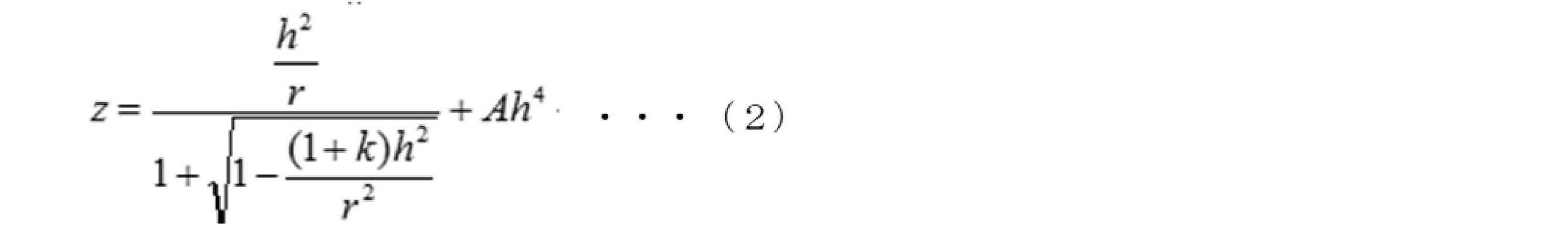
図8は、実施例に係る眼鏡レンズのセグメントの形状を示す説明図である。
図中においては、実施例に係る眼鏡レンズ1におけるセグメント6の断面形状(すなわち、上記(2)式に従うサグ量Zをベース形状に付加した形状)を、実線で示している。
図中においては、実施例に係る眼鏡レンズ1におけるセグメント6の断面形状(すなわち、上記(2)式に従うサグ量Zをベース形状に付加した形状)を、実線で示している。
このような構成の眼鏡レンズ1の製造にあたっては、まず、レンズ基材を注型重合等の公知の成形法により成形する。例えば、複数の凹部が備わった成形面を有する成形型を用い、注型重合による成形を行うことにより、少なくとも一方の表面に凸状領域を有するレンズ基材が得られる。その場合において、上記の使用に合致するように、複数の凹部が形成されてなる成形型を用いればよい。
そして、レンズ基材を得たら、次いで、そのレンズ基材の表面に、必要に応じてハードコート膜や反射防止膜等の被膜を形成する。被膜の形成は、既述した公知の成膜法を用いて行うことができる。
このような手順の製造方法により、実施例に係る眼鏡レンズ1が得られる。
そして、レンズ基材を得たら、次いで、そのレンズ基材の表面に、必要に応じてハードコート膜や反射防止膜等の被膜を形成する。被膜の形成は、既述した公知の成膜法を用いて行うことができる。
このような手順の製造方法により、実施例に係る眼鏡レンズ1が得られる。
図9は、実施例に係る眼鏡レンズのセグメントの曲率分布を示す説明図である。
図中においては、実施例に係る眼鏡レンズ1におけるセグメント6の曲率分布(すなわち、非球面形状の曲率分布)を、実線で示している。
図中においては、実施例に係る眼鏡レンズ1におけるセグメント6の曲率分布(すなわち、非球面形状の曲率分布)を、実線で示している。
図9に示すように、実施例に係る眼鏡レンズ1について、セグメント6の中心部付近の曲率は5.6[1/M]であるのに対し、セグメント6の最外部付近の曲率は4.1[1/M]と小さくなっている。
以上のようなセグメント6によれば、負の球面収差が発生し、セグメント6の最外部を透過する光線と、その最外部からセグメント6の半径の10%だけ内側を通過する光線との交わる位置が、所定位置Aである網膜20Aより1.7D手前の位置、すなわち網膜20Aと当該網膜20Aからデフォーカスしたセグメント6の焦点位置Bとの間の中間地点に存在することになる。
図10は、実施例に係る眼鏡レンズ1についてのガボール係数(評価値)のグラフの例を示す説明図である。図例のグラフは、横軸に網膜上の所定位置A(0D)と各セグメント6が焦点を結ぶ位置B(3.5D)との間の距離(デフォーカス量)を採り、縦軸にガボール係数(ガボール関数を用いた評価値)を採っており、最良フォーカス位置での値1に規格化したガボール係数(評価値)を表示している。なお、グラフ中において、中心視野20Cの分解能を考慮して計算したガボール係数については実線で示し、周辺視野20Bの分解能を考慮して計算したガボール係数(すなわち、周辺視の場合のガボール係数)については破線で示している。
図10に示すグラフによれば、破線で示す周辺視の場合に、1.7Dの地点において、ガボール係数が極大値を有していることがわかる。つまり、かかる眼鏡レンズ1において、各セグメント6が網膜上の所定位置A以外の位置に偽集光を生じさせ、その結果として、中心視野20Cに対する近視抑制効果を損なうことなく、周辺視の場合についても近視抑制効果を発揮させ得ることを確認した。
(比較例)
ここで、比較例の眼鏡レンズについて簡単に説明する。比較例の眼鏡レンズは、上述の実施例で説明した形状から、(2)式における四次非球面係数Aの項をA=0に変更したものである。すなわち、比較例の眼鏡レンズにおけるセグメントは、球面形状を持つ(図8および図9に示す破線参照)。
ここで、比較例の眼鏡レンズについて簡単に説明する。比較例の眼鏡レンズは、上述の実施例で説明した形状から、(2)式における四次非球面係数Aの項をA=0に変更したものである。すなわち、比較例の眼鏡レンズにおけるセグメントは、球面形状を持つ(図8および図9に示す破線参照)。
図11は、比較例に係る眼鏡レンズについてのガボール係数(評価値)のグラフの例を示す説明図である。図例のグラフにおいても、横軸、縦軸、実線、破線等は、図10に示すグラフの場合と同様である。
図11に示すグラフによれば、破線で示す周辺視の場合に、所定位置A(0D)において、ガボール係数が極大値を有していることがわかる。つまり、比較例に係る眼鏡レンズは、セグメントが球面収差を持たないため、所定位置A(0D)以外の位置に偽集光を生じさせることがない。したがって、比較例1に係る眼鏡レンズでは、周辺視の場合に近視抑制効果を発揮させることができない。
(変形例等)
以上に本発明の実施形態および実施例を説明したが、本発明の技術的範囲は、上述の例示的な開示内容に限定されるものではなく、その要旨を逸脱しない範囲で種々変更可能である。
以上に本発明の実施形態および実施例を説明したが、本発明の技術的範囲は、上述の例示的な開示内容に限定されるものではなく、その要旨を逸脱しない範囲で種々変更可能である。
図12は、他の実施形態における眼鏡レンズの要部構成例を示す側断面図である。
図例の眼鏡レンズは、セグメントを非球面形状とするために、デフォーカス度数を有する基材11の上に非球面層12を付与して構成されている。例えば、基材11は射出成型による樹脂レンズ基材を、非球面層12はハードコート膜を、それぞれ兼ねていてもよい。このような構成を用いることで、個人にあわせた近視抑制効果の調整が容易になる。
つまり、負の球面収差を有するセグメントは、多層構造によって構成されていてもよい。その場合、多層構造における最も内側の層(具体的には、基材11によって構成される層)は、デフォーカス度数を付与する作用を持つ層となり、それよりも外側の層(具体的には、非球面層12によって構成される層)は、負の球面収差を付与する作用を持つ層となる。
また、例えば、上述の開示内容では、物体側の面3に凸状領域6を有する構成の眼鏡レンズ1を例に挙げたが、本発明は他の構成の眼鏡レンズに適用することも可能である。すなわち、本発明は、透過光が所定位置で焦点を結ぶように形成された第1領域と、第1領域とは異なるデフォーカス位置で焦点を結ぶように形成された複数の第2領域と、を有して構成された眼鏡レンズであれば、レンズ表面に凸状領域6を有するレンズ構造のみならず、レンズ表面が平滑であるレンズ構造にも適用することが可能である。
また、例えば、上述の開示内容では、主として、眼鏡レンズが近視進行抑制レンズである場合を例に挙げたが、本発明は遠視進行抑制レンズに適用することも可能である。
また、例えば、上述の開示内容では、主として、凸状領域(セグメント)6が六方配置されている場合を例に挙げたが、本発明がこれに限定されることはない。すなわち、本発明は、六方配置以外の配置であっても、周辺視において偽集光を生じさせるように、各凸状領域(セグメント)が配置されていればよい。
1…眼鏡レンズ、3…物体側の面、4…眼球側の面、6…凸状領域(セグメント)、11…基材、12…非球面層、20…眼球、20A…網膜、20B…周辺視野、20C…中心視野
Claims (9)
- 透過光が眼内の所定位置で焦点を結ぶように形成された第1領域と、前記透過光が前記所定位置からデフォーカスした位置で焦点を結ぶように形成された複数の第2領域と、を有する眼鏡レンズであって、
前記複数の第2領域は、負の球面収差を有する
眼鏡レンズ。 - 前記複数の第2領域は、前記負の球面収差を有することで、周辺視において知覚される光が前記所定位置以外の位置における偽集光として認知されるように構成されている
請求項1に記載の眼鏡レンズ。 - 前記周辺視における前記透過光についてのガボール関数を用いた評価値が、前記所定位置以外の位置で極大値を有するように、前記複数の第2領域の球面収差が与えられている
請求項1または2に記載の眼鏡レンズ。 - 前記周辺視における前記透過光についてのガボール関数を用いた評価値が、前記所定位置以外の位置で最大値を有するように、前記複数の第2領域の球面収差が与えられている
請求項1から3のいずれか1項に記載の眼鏡レンズ。 - 前記複数の第2領域は、前記負の球面収差を有することで、前記第2領域の最外部を通過する光線と前記最外部から前記第2領域の半径の10%だけ内側を通過する光線との交わる位置が、前記所定位置と前記所定位置からデフォーカスした位置との間にあるように構成されている
請求項1から4のいずれか1項に記載の眼鏡レンズ。 - 前記複数の第2領域は、前記第2領域の中心から離れるほど曲率が小さくなるような非球面形状で形成されている
請求項1から5のいずれか1項に記載の眼鏡レンズ。 - 前記透過光が通過する瞳孔径の範囲内に前記複数の第2領域のうちの少なくとも三つが配されるとともに、当該三つの前記第2領域の各基準点を結ぶ図形が鋭角三角形となるように、前記複数の第2領域のサイズおよび配置間隔が形成されている
請求項1から6のいずれか1項に記載の眼鏡レンズ。 - 前記複数の第2領域は、六方配置されている
請求項1から7のいずれか1項に記載の眼鏡レンズ。 - 前記複数の第2領域は、多層構造によって構成されており、
前記多層構造における最も内側の層は、デフォーカス度数を付与する作用を持つ層であり、
それよりも外側の層は、負の球面収差を付与する作用を持つ層である
請求項1から8のいずれか1項に記載の眼鏡レンズ。
Priority Applications (3)
| Application Number | Priority Date | Filing Date | Title |
|---|---|---|---|
| EP21771828.7A EP4123364A4 (en) | 2020-03-17 | 2021-01-15 | GLASSES GLASS |
| US17/911,988 US20230129377A1 (en) | 2020-03-17 | 2021-01-15 | Spectacle lens |
| KR1020227021588A KR20220100070A (ko) | 2020-03-17 | 2021-01-15 | 안경 렌즈 |
Applications Claiming Priority (4)
| Application Number | Priority Date | Filing Date | Title |
|---|---|---|---|
| JP2020046050 | 2020-03-17 | ||
| JP2020-046050 | 2020-03-17 | ||
| JP2020059566A JP2021157126A (ja) | 2020-03-30 | 2020-03-30 | 眼鏡レンズ |
| JP2020-059566 | 2020-03-30 |
Publications (1)
| Publication Number | Publication Date |
|---|---|
| WO2021186873A1 true WO2021186873A1 (ja) | 2021-09-23 |
Family
ID=77677617
Family Applications (1)
| Application Number | Title | Priority Date | Filing Date |
|---|---|---|---|
| PCT/JP2021/001346 WO2021186873A1 (ja) | 2020-03-17 | 2021-01-15 | 眼鏡レンズ |
Country Status (6)
| Country | Link |
|---|---|
| US (1) | US20230129377A1 (ja) |
| EP (1) | EP4123364A4 (ja) |
| KR (1) | KR20220100070A (ja) |
| CN (2) | CN113406811A (ja) |
| TW (1) | TW202136864A (ja) |
| WO (1) | WO2021186873A1 (ja) |
Citations (5)
| Publication number | Priority date | Publication date | Assignee | Title |
|---|---|---|---|---|
| WO1996016621A1 (en) * | 1994-11-28 | 1996-06-06 | Queensland University Of Technology | Optical treatment method |
| JP2017010031A (ja) * | 2015-06-23 | 2017-01-12 | ジョンソン・アンド・ジョンソン・ビジョン・ケア・インコーポレイテッドJohnson & Johnson Vision Care, Inc. | 近視の進行を予防及び/又は鈍化するための、非共軸小型レンズを具備するコンタクトレンズ |
| US20170131567A1 (en) | 2015-11-06 | 2017-05-11 | Hoya Lens Thailand Ltd. | Spectacle Lens |
| JP2019128599A (ja) * | 2018-01-22 | 2019-08-01 | ジョンソン・アンド・ジョンソン・ビジョン・ケア・インコーポレイテッドJohnson & Johnson Vision Care, Inc. | 近視制御のための光学的非同軸ゾーンを有する眼用レンズ |
| JP2019211772A (ja) * | 2018-05-30 | 2019-12-12 | ジョンソン・アンド・ジョンソン・ビジョン・ケア・インコーポレイテッドJohnson & Johnson Vision Care, Inc. | 近視の進行を予防及び/又は鈍化するための小型レンズを含む眼用レンズ |
Family Cites Families (3)
| Publication number | Priority date | Publication date | Assignee | Title |
|---|---|---|---|---|
| US20210048689A1 (en) * | 2018-03-01 | 2021-02-18 | Essilor International | Lens element |
| KR102501015B1 (ko) * | 2018-06-29 | 2023-02-21 | 호야 렌즈 타일랜드 리미티드 | 안경 렌즈 |
| CN114286963A (zh) * | 2019-06-28 | 2022-04-05 | 华柏恩视觉研究中心有限公司 | 矫正、减缓、减少和/或控制近视进展的眼科镜片和方法 |
-
2021
- 2021-01-15 EP EP21771828.7A patent/EP4123364A4/en active Pending
- 2021-01-15 WO PCT/JP2021/001346 patent/WO2021186873A1/ja unknown
- 2021-01-15 US US17/911,988 patent/US20230129377A1/en active Pending
- 2021-01-15 KR KR1020227021588A patent/KR20220100070A/ko unknown
- 2021-01-29 TW TW110103342A patent/TW202136864A/zh unknown
- 2021-03-17 CN CN202110285580.3A patent/CN113406811A/zh active Pending
- 2021-03-17 CN CN202120548284.3U patent/CN215526263U/zh active Active
Patent Citations (5)
| Publication number | Priority date | Publication date | Assignee | Title |
|---|---|---|---|---|
| WO1996016621A1 (en) * | 1994-11-28 | 1996-06-06 | Queensland University Of Technology | Optical treatment method |
| JP2017010031A (ja) * | 2015-06-23 | 2017-01-12 | ジョンソン・アンド・ジョンソン・ビジョン・ケア・インコーポレイテッドJohnson & Johnson Vision Care, Inc. | 近視の進行を予防及び/又は鈍化するための、非共軸小型レンズを具備するコンタクトレンズ |
| US20170131567A1 (en) | 2015-11-06 | 2017-05-11 | Hoya Lens Thailand Ltd. | Spectacle Lens |
| JP2019128599A (ja) * | 2018-01-22 | 2019-08-01 | ジョンソン・アンド・ジョンソン・ビジョン・ケア・インコーポレイテッドJohnson & Johnson Vision Care, Inc. | 近視制御のための光学的非同軸ゾーンを有する眼用レンズ |
| JP2019211772A (ja) * | 2018-05-30 | 2019-12-12 | ジョンソン・アンド・ジョンソン・ビジョン・ケア・インコーポレイテッドJohnson & Johnson Vision Care, Inc. | 近視の進行を予防及び/又は鈍化するための小型レンズを含む眼用レンズ |
Non-Patent Citations (2)
| Title |
|---|
| J. DAUGMAN: "Entropy reduction and decorrelation in visual coding by oriented neural receptive fields", TRANS. ON BIOMEDICAL ENGINEERING, vol. 36, no. 1, 1989, pages 107 - 114, XP000098612, DOI: 10.1109/10.16456 |
| See also references of EP4123364A4 |
Also Published As
| Publication number | Publication date |
|---|---|
| CN113406811A (zh) | 2021-09-17 |
| CN215526263U (zh) | 2022-01-14 |
| TW202136864A (zh) | 2021-10-01 |
| KR20220100070A (ko) | 2022-07-14 |
| US20230129377A1 (en) | 2023-04-27 |
| EP4123364A1 (en) | 2023-01-25 |
| EP4123364A4 (en) | 2024-05-15 |
Similar Documents
| Publication | Publication Date | Title |
|---|---|---|
| WO2021132079A1 (ja) | 眼鏡レンズ | |
| KR20190076005A (ko) | 근시 제어를 위한 장치, 시스템 및/또는 방법 | |
| WO2014054946A1 (en) | Artificial asymmetrical pupil for extended depth of field | |
| CN216434562U (zh) | 眼镜片及光学眼镜 | |
| JP2021157126A (ja) | 眼鏡レンズ | |
| CN112703443B (zh) | 眼用透镜、其设计方法、制造方法以及眼用透镜组 | |
| CN113474718B (zh) | 眼科镜片 | |
| JP7358619B2 (ja) | 眼鏡レンズ | |
| WO2021186873A1 (ja) | 眼鏡レンズ | |
| JP7488328B2 (ja) | 眼鏡レンズ | |
| CN109313360A (zh) | 眼科镜片和其制造方法 | |
| KR20230003018A (ko) | 안경 렌즈 | |
| CN113341593A (zh) | 具有离焦功能的眼镜片 | |
| KR102557131B1 (ko) | 안경 렌즈 및 안경 렌즈 설계 방법 | |
| CN215117041U (zh) | 眼镜片 | |
| KR100504388B1 (ko) | 비축 비구면 다초점 광학 렌즈 | |
| WO2023171061A1 (ja) | 眼鏡レンズ、および眼鏡レンズの設計方法 | |
| CN113341592A (zh) | 眼镜片 | |
| KR20240021301A (ko) | 안경 렌즈 | |
| JP2022136680A (ja) | 眼鏡レンズ及びその設計方法 | |
| KR20240021302A (ko) | 안경 렌즈 | |
| CN117970665A (zh) | 一种离焦眼镜片及眼镜 |
Legal Events
| Date | Code | Title | Description |
|---|---|---|---|
| 121 | Ep: the epo has been informed by wipo that ep was designated in this application |
Ref document number: 21771828 Country of ref document: EP Kind code of ref document: A1 |
|
| ENP | Entry into the national phase |
Ref document number: 20227021588 Country of ref document: KR Kind code of ref document: A |
|
| NENP | Non-entry into the national phase |
Ref country code: DE |
|
| ENP | Entry into the national phase |
Ref document number: 2021771828 Country of ref document: EP Effective date: 20221017 |