WO2021186660A1 - 無線通信装置 - Google Patents
無線通信装置 Download PDFInfo
- Publication number
- WO2021186660A1 WO2021186660A1 PCT/JP2020/012207 JP2020012207W WO2021186660A1 WO 2021186660 A1 WO2021186660 A1 WO 2021186660A1 JP 2020012207 W JP2020012207 W JP 2020012207W WO 2021186660 A1 WO2021186660 A1 WO 2021186660A1
- Authority
- WO
- WIPO (PCT)
- Prior art keywords
- antenna
- unit
- antennas
- signal
- wireless communication
- Prior art date
- Legal status (The legal status is an assumption and is not a legal conclusion. Google has not performed a legal analysis and makes no representation as to the accuracy of the status listed.)
- Ceased
Links
Images


Classifications
-
- H—ELECTRICITY
- H04—ELECTRIC COMMUNICATION TECHNIQUE
- H04B—TRANSMISSION
- H04B7/00—Radio transmission systems, i.e. using radiation field
- H04B7/02—Diversity systems; Multi-antenna system, i.e. transmission or reception using multiple antennas
- H04B7/04—Diversity systems; Multi-antenna system, i.e. transmission or reception using multiple antennas using two or more spaced independent antennas
- H04B7/06—Diversity systems; Multi-antenna system, i.e. transmission or reception using multiple antennas using two or more spaced independent antennas at the transmitting station
Definitions
- This disclosure relates to a wireless communication device.
- MIMO Multiple Input Multiple Output
- a non-reflective antenna In order to realize MIMO transmission efficiently, it is important to use a non-reflective antenna.
- the absence of reflection means that radio waves are normally transmitted from the antenna, and conversely, the presence of reflection means that there is a problem in transmitting radio waves from the antenna.
- the characteristics of the individual antennas are different, that is, the correlation between the antennas is weak.
- the characteristics of the individual antennas are similar, that is, when the correlation between the antennas is strong, it is difficult to distinguish which antenna the signal was transmitted and received, and the transmission speed does not increase.
- the physical distance between the antennas becomes short and the isolation between the antennas cannot be secured, so there is a problem that the antenna characteristics tend to be similar. there were.
- the antenna characteristics change when the human body and metals approach the antenna in the product, the characteristics of each antenna are different in a so-called free space environment where the human body and metals do not exist nearby. Even so, there is a problem that the characteristics of each antenna become similar due to changes in the surrounding environment, and as a result, the transmission packet error of MIMO transmission increases and the communication speed is extremely deteriorated.
- Patent Document 1 a reference signal is transmitted from each antenna, the degree of coupling between the antennas when the reference signal is received by another antenna is determined, and the antenna to be used is used based on the determination result.
- An antenna selection method for selecting is proposed.
- the degree of coupling between the antennas referred to here is the amount of isolation, and is a value indicating how much the reference signal transmitted from one antenna A is absorbed by another antenna B.
- Patent Document 1 proposes an antenna selection method in which when a reference signal is transmitted from each antenna, the detection unit detects the presence or absence of reflection in the antenna that transmits the reference signal and does not select the antenna with reflection. ing.
- the antenna selection method described in Patent Document 1 was effective only when the number of antennas or receivers and the number of transmitters were the same.
- the transmission speed is increased by using more antennas at the time of reception than at the time of transmission.
- the wireless communication device needs to include four transmitters and four signal detectors for four antennas. There was a problem that the scale of the branch circuit became large.
- the present disclosure has been made in order to solve the above-mentioned problems, and is a wireless communication device that selects an antenna to be used from a plurality of antennas, and has a number of transmitters and a signal as compared with the number of antennas.
- An object of the present invention is to provide a wireless communication device having a small number of detection units.
- the wireless communication device includes n (n ⁇ 2) antennas, n receivers connected to each of the n antennas, m (m ⁇ n) transmitters, and m.
- the m signal detection units connected to each of the transmission units, the first switching unit that individually switches a plurality of connection paths connecting the n antennas and the m signal detection units, and m units.
- One antenna characteristic confirmation unit that outputs a reference signal to each of the m signal detection units via each of the transmission units, and one antenna that transmits a reference signal by switching the connection path to the first switching unit.
- the reflected signal reflected by the antenna that transmitted the reference signal while switching is detected by the signal detection unit that outputs the reference signal, and one of the n antennas used for communication based on the detection results by the m signal detection units. It includes a control unit that selects the above antennas, and a wireless communication signal processing unit that communicates using one or more antennas selected by the control unit.
- the antenna connected to the transmitting unit that outputs the reference signal can be switched by the first switching unit, it is possible to provide a wireless communication device in which the number of transmitting units is smaller than the number of antennas. Can be done.
- FIG. It is a block diagram which shows the structural example of the wireless communication apparatus which concerns on Embodiment 1.
- FIG. It is a flowchart which shows the operation example of the wireless communication apparatus which concerns on Embodiment 1.
- FIG. It is a flowchart which shows the operation example for confirming the antenna characteristic in step ST2 of FIG.
- FIG. It is a block diagram which shows an example of the hardware composition of the wireless communication apparatus which concerns on each embodiment.
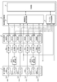
- FIG. 1 is a block diagram showing a configuration example of the wireless communication device according to the first embodiment.
- the wireless communication device shown in FIG. 1 includes four antennas Ant1, Ant2, Ant3, Ant4, four receiving units RX1, RX2, RX3, RX4 having the same number as the antennas, and two transmitting units TX12, which are less than the antennas. , TX34 and two signal detection units SD12 and SD34, which are the same number as the transmission unit.
- This wireless communication device operates MIMO with a maximum of two antennas during transmission and a maximum of four antennas during reception.
- the receiving units RX1, RX2, RX3, and RX4 perform demodulation processing and the like on the input signal.
- the transmission units TX12 and TX34 perform modulation processing and the like on the input signal.
- this wireless communication device has a configuration including a first switching unit 1, a second switching unit 2, a wireless communication signal processing unit 3, a control unit 4, and an antenna characteristic confirmation unit 5.
- the wireless communication signal processing unit 3, the control unit 4, and the antenna characteristic confirmation unit 5 constitute a wireless communication control unit 6.
- the first switching unit 1 includes switches SW1, SW12, SW2, SW3, SW34, and SW4.
- the second switching unit 2 includes switches SW1R, SW12T, SW2R, SW3R, SW34T, and SW4R. The operation of each switch included in the first switching unit 1 and each switch included in the second switching unit 2 is controlled by the control unit 4.
- the receiving unit RX1 is connected to the antenna Ant1 via the switch SW1.
- the wireless communication signal processing unit 3 and the antenna characteristic confirmation unit 5 are connected to the receiving unit RX1 via the switch SW1R.
- the receiving unit RX2 is connected to the antenna Ant2 via the switch SW2.
- the wireless communication signal processing unit 3 and the antenna characteristic confirmation unit 5 are connected to the receiving unit RX2 via the switch SW2R.
- the receiving unit RX3 is connected to the antenna Ant3 via the switch SW3.
- the wireless communication signal processing unit 3 and the antenna characteristic confirmation unit 5 are connected to the receiving unit RX3 via the switch SW3R.
- the receiving unit RX4 is connected to the antenna Ant4 via the switch SW4.
- the wireless communication signal processing unit 3 and the antenna characteristic confirmation unit 5 are connected to the receiving unit RX4 via the switch SW4R.
- the transmission unit TX12 is connected to the antenna Ant1 via the switch SW1, the switch SW12, and the signal detection unit SD12.
- the transmission unit TX12 is connected to the antenna Ant2 via the switch SW2, the switch SW12, and the signal detection unit SD12.
- the wireless communication signal processing unit 3 and the antenna characteristic confirmation unit 5 are connected to the transmission unit TX12 via the switch SW12T.
- the control unit 4 When transmitting a signal from the antenna Ant1, the control unit 4 connects the transmission unit TX12 to the antenna Ant1 by a connection path passing through the signal detection unit SD12, the switch SW12, and the switch SW1.
- the control unit 4 connects the transmission unit TX12 to the antenna Ant2 by a connection path passing through the signal detection unit SD12, the switch SW12, and the switch SW2.
- the transmission unit TX34 is connected to the antenna Ant3 via the switch SW3, the switch SW34, and the signal detection unit SD34.
- the transmission unit TX34 is connected to the antenna Ant4 via the switch SW4, the switch SW34, and the signal detection unit SD34.
- the wireless communication signal processing unit 3 and the antenna characteristic confirmation unit 5 are connected to the transmission unit TX34 via the switch SW34T.
- the control unit 4 When transmitting a signal from the antenna Ant3, the control unit 4 connects the transmission unit TX34 to the antenna Ant3 by a connection path passing through the signal detection unit SD34, the switch SW34, and the switch SW3.
- the control unit 4 connects the transmission unit TX34 to the antenna Ant4 by a connection path passing through the signal detection unit SD34, the switch SW34, and the switch SW4.
- the control unit 4 can connect the signal detection unit SD12 to the antenna Ant1 or the antenna Ant2 and connect the signal detection unit SD34 to the antenna Ant3 or the antenna Ant4 by switching the connection destination of each switch of the first switching unit 1. can. Therefore, the number of transmitting units and the number of signal detecting units can be smaller than the number of antennas and the number of receiving units.
- This wireless communication device performs a wireless communication mode for performing normal wireless communication and an antenna characteristic confirmation mode for confirming the antenna characteristics of the antennas Ant1, Ant2, Ant3, and Ant4 and selecting the antenna to be used in the wireless communication mode.
- the control unit 4 controls switching between the wireless communication mode and the antenna characteristic confirmation mode.
- the control unit 4 notifies the wireless communication signal processing unit 3 and the antenna characteristic confirmation unit 5 of the mode to be executed.
- the wireless communication signal processing unit 3 executes the wireless communication mode in accordance with the notification from the control unit 4.
- the antenna characteristic confirmation unit 5 executes the antenna characteristic confirmation mode in accordance with the notification from the control unit 4.
- the antenna characteristic confirmation mode In the antenna characteristic confirmation mode, the presence or absence of reflection of the antennas Ant1, Ant2, Ant3, and Ant4 is confirmed. In this antenna characteristic confirmation mode, in addition to confirming the presence or absence of reflection of the antennas Ant1, Ant2, Ant3, and Ant4, the correlation between the antennas may be confirmed. In the following example, in the antenna characteristic confirmation mode, the presence or absence of reflection of the antennas Ant1, Ant2, Ant3, and Ant4 is confirmed, and the correlation between the antennas is confirmed.
- An antenna without reflection is an antenna having good radiation characteristics.
- an antenna with reflection is an antenna having poor radiation characteristics.
- the correlation between the two antennas is weak.
- the characteristics of the two antennas are similar, the correlation between the two antennas is strong.
- the radiation characteristics of each of the two antennas are good, it can be said that the correlation between the two antennas is weak and the degree of coupling between the two antennas is also small.
- the degree of coupling may be small even if the correlation between the two antennas is strong. Therefore, in the present disclosure, the presence or absence of reflection of the antenna is first confirmed.
- the wireless communication signal processing unit 3 At the time of transmission in the wireless communication mode, the wireless communication signal processing unit 3 generates a signal (hereinafter referred to as "transmission signal") to be transmitted to the wireless communication device (not shown) on the other side.
- transmission signal a signal
- the wireless communication signal processing unit 3 transmits the generated transmission signal via the switch SW12T, the transmission unit TX12, the signal detection unit SD12, the switch SW12, and the switch SW1. Output to antenna Ant1.
- the wireless communication signal processing unit 3 transmits the generated transmission signal via the switch SW12T, the transmission unit TX12, the signal detection unit SD12, the switch SW12, and the switch SW2. Output to antenna Ant2.
- the wireless communication signal processing unit 3 transmits the generated transmission signal via the switch SW34T, the transmission unit TX34, the signal detection unit SD34, the switch SW34, and the switch SW3. Output to antenna Ant3.
- the wireless communication signal processing unit 3 transmits the generated transmission signal via the switch SW34T, the transmission unit TX34, the signal detection unit SD34, the switch SW34, and the switch SW4. Output to antenna Ant4.
- the signal detection unit SD12 detects the strength of the transmission signal input from the transmission unit TX12 and outputs the detection result to the wireless communication signal processing unit 3.
- the signal detection unit SD34 detects the strength of the transmission signal input from the transmission unit TX34 and outputs the detection result to the wireless communication signal processing unit 3.
- the wireless communication signal processing unit 3 Based on the detection results by the signal detection units SD12 and SD34, the wireless communication signal processing unit 3 has the transmission unit TX12, so that the strength of the transmission signal transmitted from the antennas Ant1, Ant2, Ant3, and Ant4 does not deviate from the product specifications. The strength of the transmission signal output to the TX34 is controlled.
- the wireless communication signal processing unit 3 requests the strength of the transmission signal transmitted from the antennas Ant1, Ant2, Ant3, and Ant4 from the wireless communication device on the other side based on the detection results by the signal detection units SD12 and SD34.
- the strength of the transmission signal output to the transmission units TX12 and TX34 may be manipulated so that the signal strength corresponds to the signal strength.
- the antenna Ant1 When the antenna Ant1 is selected as the antenna to be used when receiving in the wireless communication mode, the signal transmitted by the wireless communication device on the other side is received by the antenna Ant1 and passes through the switch SW1, the receiving unit RX1 and the switch SW1R. Then, it is output to the wireless communication signal processing unit 3.
- the antenna Ant2 When the antenna Ant2 is selected as the antenna to be used, the signal transmitted by the wireless communication device on the other side is received by the antenna Ant2, and the wireless communication signal processing is performed via the switch SW2, the receiving unit RX2, and the switch SW2R. It is output to part 3.
- the antenna Ant3 When the antenna Ant3 is selected as the antenna to be used, the signal transmitted by the wireless communication device on the other side is received by the antenna Ant3, and the wireless communication signal processing is performed via the switch SW3, the receiving unit RX3, and the switch SW3R. It is output to part 3.
- the antenna Ant4 When the antenna Ant4 is selected as the antenna to be used, the signal transmitted by the wireless communication device on the other side is received by the antenna Ant4, and the wireless communication signal processing is performed via the switch SW4, the receiving unit RX4, and the switch SW4R. It is output to part 3.
- the antenna characteristic confirmation unit 5 In the antenna characteristic confirmation mode, the antenna characteristic confirmation unit 5 generates a predetermined signal (hereinafter, referred to as “reference signal”).
- reference signal a predetermined signal
- the antenna characteristic confirmation unit 5 transfers the generated reference signal to the switch SW12T, the transmission unit TX12, and the signal detection unit SD12. It outputs to the antenna Ant1 via the switch SW12 and the switch SW1.
- the reference signal reflected by the antenna Ant1 (hereinafter referred to as “reflected signal”) while the antenna Ant1 is transmitting the reference signal returns to the signal detection unit SD12 via the switch SW1 and the switch SW12, and is a signal. It is detected by the detection unit SD12.
- the reference signal received by the antenna Ant2 (hereinafter referred to as “received signal”) is output to the antenna characteristic confirmation unit 5 via the receiving unit RX2 and the switch SW2R.
- the received signal received by the antennas Ant3 and Ant4 is output to the antenna characteristic confirmation unit 5 via the receiving units RX3 and RX4 and the switches SW3R and SW4R.
- the antenna characteristic confirmation unit 5 uses the switch SW12T, the transmission unit TX12 and the signal detection unit SD12 to transfer the generated reference signal. It outputs to the antenna Ant2 via the switch SW12 and the switch SW2.
- the reflected signal reflected by the antenna Ant2 while the antenna Ant2 is transmitting the reference signal returns to the signal detection unit SD12 via the switch SW2 and the switch SW12, and is detected by the signal detection unit SD12.
- the received signal received by the antenna Ant1 is output to the antenna characteristic confirmation unit 5 via the receiving unit RX1 and the switch SW1R.
- the received signal received by the antennas Ant3 and Ant4 is output to the antenna characteristic confirmation unit 5 via the receiving units RX3 and RX4 and the switches SW3R and SW4R.
- the antenna characteristic confirmation unit 5 uses the switch SW34T, the transmission unit TX34, and the signal detection unit SD34 to transfer the generated reference signal. It outputs to the antenna Ant3 via the switch SW34 and the switch SW3.
- the reflected signal reflected by the antenna Ant3 while the antenna Ant3 is transmitting the reference signal returns to the signal detection unit SD34 via the switch SW3 and the switch SW34, and is detected by the signal detection unit SD34.
- the received signal received by the antenna Ant1 is output to the antenna characteristic confirmation unit 5 via the receiving unit RX1 and the switch SW1R.
- the received signal received by the antennas Ant2 and Ant4 is output to the antenna characteristic confirmation unit 5 via the receiving units RX2 and RX4 and the switches SW2R and SW4R.
- the antenna characteristic confirmation unit 5 uses the switch SW34T, the transmission unit TX34, and the signal detection unit SD34 to transfer the generated reference signal. It outputs to the antenna Ant4 via the switch SW34 and the switch SW4.
- the reflected signal reflected by the antenna Ant4 while the antenna Ant4 is transmitting the reference signal returns to the signal detection unit SD34 via the switch SW4 and the switch SW34, and is detected by the signal detection unit SD34.
- the received signal received by the antenna Ant1 is output to the antenna characteristic confirmation unit 5 via the receiving unit RX1 and the switch SW1R.
- the received signal received by the antennas Ant2 and Ant3 is output to the antenna characteristic confirmation unit 5 via the receiving units RX2 and RX3 and the switches SW2R and SW3R.
- the signal detection units SD12 and SD34 output the presence or absence of the detected reflected signal to the antenna characteristic confirmation unit 5.
- the signal detection units SD12 and SD34 determine, for example, that there is a reflected signal when the intensity of the reflected signal is equal to or higher than the predetermined intensity, and when the intensity of the reflected signal is less than the predetermined intensity, the reflected signal Judge as none.
- the antenna characteristic confirmation unit 5 outputs a detection result indicating whether or not a reflected signal is detected in each of the antennas Ant1, Ant2, Ant3, and Ant4 to the control unit 4. Further, the antenna characteristic confirmation unit 5 outputs information indicating the strength of the received signal received by the reception units RX1, RX2, RX3, and RX4 to the control unit 4.
- the control unit 4 selects at least one antenna to be used in the wireless communication mode from the antennas Ant1, Ant2, Ant3, and Ant4 based on the detection result of the reflected signal and the strength of the received signal.
- the control unit 4 outputs information indicating the selected antenna to the wireless communication signal processing unit 3.
- FIG. 2 is a flowchart showing an operation example of the wireless communication device according to the first embodiment.
- the control unit 4 instructs the wireless communication signal processing unit 3 and the antenna characteristic confirmation unit 5 to switch to the antenna characteristic confirmation mode (step). ST1).
- the wireless communication signal processing unit 3 interrupts the wireless communication mode.
- the control unit 4 switches the connection destination of each switch of the second switching unit 2 from the wireless communication signal processing unit 3 to the antenna characteristic confirmation unit 5.
- the antenna characteristic confirmation unit 5 Upon receiving the instruction to switch to the antenna characteristic confirmation mode, the antenna characteristic confirmation unit 5 confirms the antenna characteristics of the antennas Ant1, Ant2, Ant3, and Ant4 (step ST2).
- FIG. 3 is a flowchart showing an operation example for confirming the antenna characteristics in step ST2 of FIG.
- the control unit 4 resets the antenna number N to "1" (step ST11).
- the number N 4 points to the antenna Ant4.
- the signal detection unit SD12 connected to the antenna Ant1 detects the presence or absence of a reflected signal from the antenna Ant1 that has transmitted the reference signal, and outputs the detection result to the antenna characteristic confirmation unit 5 (step ST14). Further, the receiving units RX2, RX3, and RX4 output the received signal received by the antennas Ant2, Ant3, and Ant4 to the antenna characteristic confirmation unit 5 (step ST15).
- the antenna characteristic confirmation unit 5 outputs information indicating the detection result of the reflected signal and the strength of the received signal to the control unit 4.
- step ST16 “YES”) When the reflected signal is detected by the antenna Ant1 (step ST16 “YES”), the control unit 4 excludes the antenna Ant1 from the target of use in the wireless communication mode and also the target of the correlation confirmation described later. On the other hand, when the reflected signal is not detected by the antenna Ant1 (step ST16 “NO”), the process of the control unit 4 proceeds to step ST18. That is, when the reflected signal is not detected by the antenna Ant1, the antenna Ant1 is the object to be used in the wireless communication mode.
- the control unit 4 changes the antenna number N to "N + 1" (step ST18).
- control unit 4 selects an antenna to be used in the wireless communication mode based on the antenna characteristic confirmation result by the antenna characteristic confirmation unit 5 (step ST3).
- FIG. 4 is a table showing an example of the antenna characteristic confirmation result.
- the control unit 4 sets the antenna Ant2 and the antenna Ant4, for which "no reflection" is confirmed, as targets for use in the wireless communication mode and targets for correlation confirmation, which will be described later.
- the control unit 4 excludes the antenna Ant1 and the antenna Ant3 confirmed to have "reflection" from the objects to be used in the wireless communication mode and also from the objects to be confirmed for correlation, which will be described later.
- the control unit 4 confirms the correlation between the antenna Ant2 and the antenna Ant4.
- the received signal strength of the antenna Ant4 when the antenna Ant2 transmits the reference signal is “weak”, and the received signal strength of the antenna Ant2 when the antenna Ant4 transmits the reference signal is also “weak”. Therefore, the control unit 4 determines that the correlation between the antenna Ant2 and the antenna Ant4 is weak, and selects the antenna Ant2 and the antenna Ant4 as the antenna to be used in the wireless communication mode.
- the received signal strength is shown in two stages of "weak” and “strong”, but it may be shown in three or more steps, or it may be shown numerically.
- step ST4 “YES”) the control unit 4 instructs the wireless communication signal processing unit 3 and the antenna characteristic confirmation unit 5 to switch to the wireless communication mode (step ST5). ).
- the antenna characteristic confirmation unit 5 ends the antenna characteristic confirmation mode.
- the wireless communication signal processing unit 3 restarts the wireless communication mode and performs wireless communication using the antenna selected by the control unit 4. Further, the control unit 4 switches the connection destination of each switch of the second switching unit 2 from the antenna characteristic confirmation unit 5 to the wireless communication signal processing unit 3.
- step ST4 “NO”) the control unit 4 re-executes the antenna characteristic confirmation mode (step ST2).
- the antenna characteristics change due to changes in the surrounding environment, it becomes possible to dynamically select an antenna that can be used, and as a result, it becomes possible to perform wireless communication in an optimum state.
- control unit 4 may perform the operation shown in the flowchart of FIG. 2 before the wireless communication with the wireless communication device on the other side starts. Further, the control unit 4 may periodically perform the operation shown in the flowchart of FIG. 2 during wireless communication with the wireless communication device on the other side. As a result, when the antenna characteristics change due to changes in the surrounding environment, it becomes possible to dynamically select an antenna that can be used, and as a result, it becomes possible to perform wireless communication in an optimum state.
- the wireless communication device of the other party receives information on the transmission speed estimated from the number of antennas used, the number of antennas used, and the like. May be notified to. Communication errors can be prevented and, as a result, deterioration of communication quality can be prevented by performing transmission operations between wireless communication devices according to the number of antennas on the other side or the transmission speed.
- the wireless communication device includes antennas Ant1, Ant2, Ant3, Ant4, reception units RX1, RX2, RX3, RX4 having the same number of antennas, and transmission units TX12, which is smaller than the number of antennas. It includes a TX34, the same number of signal detection units SD12 and SD34 as the transmission unit, a first switching unit 1, an antenna characteristic confirmation unit 5, a control unit 4, and a wireless communication signal processing unit 3.
- the first switching unit 1 individually switches a plurality of connection paths connecting the antennas Ant1, Ant2, Ant3, and Ant4 and the signal detection units SD12 and SD34.
- the antenna characteristic confirmation unit 5 outputs a reference signal to each of the signal detection units SD12 and SD34 via the transmission units TX12 and TX34, respectively.
- the control unit 4 switches the antenna for transmitting the reference signal one by one by causing the first switching unit 1 to switch the connection path, and at the same time, the antenna that transmits the reference signal among the antennas Ant1, Ant2, Ant3, and Ant4.
- the reflected reflected signal is detected by the signal detection unit that outputs the reference signal among the signal detection units SD12 and SD34, and the antennas Ant1, Ant2, Ant3 and Ant4 are based on the detection result of the reflected signal by the signal detection units SD12 and SD34. Select one or more antennas to be used for communication from among them.
- the wireless communication signal processing unit 3 communicates using one or more antennas selected by the control unit 4.
- the circuit scale of the first switching unit 1 is smaller than the circuit scale of the transmission unit and the signal detection unit, the number of antennas is the same as the number of transmission units and the number of signal detection units. Compared with the above, the circuit scale of the wireless communication device according to the first embodiment can be reduced, and the current consumption can also be reduced.
- control unit 4 interrupts the communication while the wireless communication signal processing unit 3 is communicating, outputs a reference signal from the antenna characteristic confirmation unit 5, and displays the antenna. Reselect one or more antennas used for communication from Ant1, Ant2, Ant3, and Ant4. As a result, the antenna characteristics due to changes in the antenna surrounding environment in the wireless communication mode can be constantly monitored, so that the antenna that can be used can be dynamically selected.
- the control unit 4 is based on the strength of the reference signal received by each of the one or more antennas selected based on the detection result of the reflected signal by the signal detection units SD12 and SD34. , The correlation between the antenna that transmitted the reference signal and the antenna that received the reference signal is confirmed, and the antenna used for communication is selected from the one or more antennas based on the correlation between the antennas. As a result, the control unit 4 can select an antenna that is more suitable for communication.
- the first switching unit 1 switches the two connection paths to which the two antennas Ant1 and Ant2 are connected to the signal detection unit SD12.
- the two connection paths are a path in which the antenna Ant1, the switch SW1, the switch SW12, and the signal detection unit SD12 are connected, and a route in which the antenna Ant2, the switch SW2, the switch SW12, and the signal detection unit SD12 are connected. .. Further, the first switching unit 1 switches between two connection paths to which the two antennas Ant3 and Ant4 are connected to the signal detection unit SD34.
- the two connection paths are a path in which the antenna Ant3, the switch SW3, the switch SW34, and the signal detection unit SD34 are connected, and a route in which the antenna Ant4, the switch SW4, the switch SW34, and the signal detection unit SD34 are connected. ..
- the number of transmitting units can be halved and the number of signal detecting units can be halved with respect to the number of antennas.
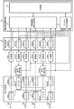
- FIG. 5 is a block diagram showing a configuration example of the wireless communication device according to the second embodiment.
- the same or corresponding parts as those in FIG. 1 are designated by the same reference numerals, and the description thereof will be omitted.
- the signal from the transmitting unit TX12 is transmitted from the antenna Ant1 or the antenna Ant2, and the signal from the transmitting unit TX34 is transmitted from the antenna Ant3 or the antenna Ant4.
- the signal from the transmitting unit TX12 is transmitted from any one of the antennas Ant1, Ant2, Ant3 and Ant4, and the signal from the transmitting unit TX34 is also transmitted from the antennas Ant1, Ant2, Ant3 and Ant4. It is a configuration sent from one of them.
- antenna Ant1 and antenna Ant2 that is, if it is determined that antenna Ant3 and antenna Ant4 cannot be used, either antenna Ant1 or antenna Ant2 is used at the time of transmission. One antenna will be used and MIMO operation will not be possible.
- antenna Ant1 and antenna Ant2 since it is possible to transmit from both the antenna Ant1 and the antenna Ant2, efficient communication is possible without lowering the upstream transmission speed.
- the first switching unit 1 in the second embodiment includes switches SW1a, SW2a, SW3a, SW4a, SW12, SW34, SW1b, SW2b, SW3b, SW4b.
- the operation of each switch included in the first switching unit 1 is controlled by the control unit 4.
- the receiving unit RX1 is connected to the antenna Ant1 via the switch SW1a and the switch SW1b.
- the receiving unit RX2 is connected to the antenna Ant2 via the switch SW2a and the switch SW2b.
- the receiving unit RX3 is connected to the antenna Ant3 via the switch SW3a and the switch SW3b.
- the receiving unit RX4 is connected to the antenna Ant4 via the switch SW4a and the switch SW4b.
- the transmission unit TX12 is connected to the antenna Ant1 via the switch SW1a, the switch SW1b, the switch SW12, and the signal detection unit SD12. Further, the transmission unit TX34 is connected to the antenna Ant1 via the switch SW1a, the switch SW34, and the signal detection unit SD34.
- the transmission unit TX12 is connected to the antenna Ant2 via the switch SW2a, the switch SW2b, the switch SW12, and the signal detection unit SD12. Further, the transmission unit TX34 is connected to the antenna Ant2 via the switch SW2a, the switch SW34, and the signal detection unit SD34.
- the transmission unit TX12 is connected to the antenna Ant3 via the switch SW3a, the switch SW3b, the switch SW12, and the signal detection unit SD12. Further, the transmission unit TX34 is connected to the antenna Ant3 via the switch SW3a, the switch SW34, and the signal detection unit SD34.
- the transmission unit TX12 is connected to the antenna Ant4 via the switch SW4a, the switch SW4b, the switch SW12, and the signal detection unit SD12. Further, the transmission unit TX34 is connected to the antenna Ant4 via the switch SW4a, the switch SW34, and the signal detection unit SD34.
- the control unit 4 can connect the signal detection unit SD12 to any of the antennas Ant1, Ant2, Ant3, and Ant4 by switching the connection destination of each switch of the first switching unit 1, and also connects the signal detection unit SD34 to the antenna. It can be connected to any of Ant1, Ant2, Ant3, and Ant4. Therefore, the number of transmitting units and the number of signal detecting units can be smaller than the number of antennas and the number of receiving units.
- the first switching unit 1 in the wireless communication device provides four connection paths in which four antennas Ant1, Ant2, Ant3, and Ant4 are connected to the signal detection unit SD12.
- the four connection paths are the path where the antenna Ant1, the switch SW1a, the switch SW1b, the switch SW12, and the signal detection unit SD12 are connected, and the antenna Ant2, the switch SW2a, the switch SW2b, the switch SW12, and the signal detection unit SD12 are connected.
- the first switching unit 1 switches the four connection paths to which the four antennas Ant1, Ant2, Ant3, and Ant4 are connected to the signal detection unit SD34.
- the four connection paths are the path where the antenna Ant1, the switch SW1a, the switch SW34, and the signal detection unit SD34 are connected, the path where the antenna Ant2, the switch SW2a, the switch SW34, and the signal detection unit SD34 are connected, and the antenna Ant3.
- This is a route in which the switch SW3a, the switch SW34, and the signal detection unit SD34 are connected, and a route in which the antenna Ant4, the switch SW4a, the switch SW34, and the signal detection unit SD34 are connected.
- FIGS. 6 and 7 are diagrams showing a hardware configuration example of the wireless communication device according to each embodiment.
- Each function in the wireless communication device is realized by a processing circuit. That is, the wireless communication device includes a processing circuit for realizing each of the above functions.
- the processing circuit may be processing circuits 100, 100a as dedicated hardware, or may be a processor 101 that executes a program stored in the memory 102.
- the processing circuit 100 may be, for example, a single circuit, a composite circuit, a programmed processor, a parallel programmed processor, or an ASIC (Application Specific Integrated Circuit). ), FPGA (Field Processor Gate Array), or a combination thereof.
- the functions of the above may be realized by a plurality of processing circuits 100, or the functions of each part may be collectively realized by one processing circuit 100.
- the processing circuit is the processor 101
- the function of the wireless communication control unit 6 is realized by software, firmware, or a combination of software and firmware.
- the software or firmware is described as a program and stored in the memory 102.
- the processor 101 realizes the functions of each part by reading and executing the program stored in the memory 102. That is, the wireless communication device includes a memory 102 for storing a program in which the steps shown in the flowcharts of FIGS. 2 and 3 are eventually executed when executed by the processor 101. It can also be said that this program causes the computer to execute the procedure or method of the wireless communication control unit 6.
- the functions of the antennas Ant1, Ant2, Ant3, Ant4, the first switching unit 1, the second switching unit 2, the receiving unit RX1, RX2, RX3, RX4, the transmitting unit TX12, TX34, and the signal detecting units SD12, SD34 are It is realized by the processing circuit 100a, which is dedicated hardware.
- the processor 101 is a CPU (Central Processing Unit), a processing device, an arithmetic unit, a microprocessor, or the like.
- the memory 102 may be a non-volatile or volatile semiconductor memory such as a RAM (Random Access Memory), a ROM (Read Only Memory), an EPROM (Erasable Programmable ROM), or a flash memory, and may be a non-volatile or volatile semiconductor memory such as a hard disk or a flexible disk. It may be a magnetic disk of the above, or an optical disk such as a CD (Compact Disc) or a DVD (Digital Versaille Disc).
- Some of the functions of Part 6 may be realized by dedicated hardware, and some may be realized by software or firmware.
- the processing circuit in the wireless communication device can realize the above-mentioned functions by hardware, software, firmware, or a combination thereof.
- the present disclosure allows any combination of embodiments, modifications of any component of each embodiment, or omission of any component of each embodiment.
- the configuration in which the wireless communication device includes four antennas has been described, but the number of antennas is not limited to four. However, the number of antennas and receivers must be the same. Further, since a plurality of antennas are connected to one transmitting unit via the first switching unit, the number of transmitting units is smaller than the number of antennas. The number of transmitters and signal detectors must be the same.
- the wireless communication device is suitable for use in a wireless communication device or the like that performs MIMO transmission.
Landscapes
- Engineering & Computer Science (AREA)
- Computer Networks & Wireless Communication (AREA)
- Signal Processing (AREA)
- Radio Transmission System (AREA)
- Mobile Radio Communication Systems (AREA)
Priority Applications (2)
| Application Number | Priority Date | Filing Date | Title |
|---|---|---|---|
| JP2022507951A JPWO2021186660A1 (https=) | 2020-03-19 | 2020-03-19 | |
| PCT/JP2020/012207 WO2021186660A1 (ja) | 2020-03-19 | 2020-03-19 | 無線通信装置 |
Applications Claiming Priority (1)
| Application Number | Priority Date | Filing Date | Title |
|---|---|---|---|
| PCT/JP2020/012207 WO2021186660A1 (ja) | 2020-03-19 | 2020-03-19 | 無線通信装置 |
Publications (1)
| Publication Number | Publication Date |
|---|---|
| WO2021186660A1 true WO2021186660A1 (ja) | 2021-09-23 |
Family
ID=77771951
Family Applications (1)
| Application Number | Title | Priority Date | Filing Date |
|---|---|---|---|
| PCT/JP2020/012207 Ceased WO2021186660A1 (ja) | 2020-03-19 | 2020-03-19 | 無線通信装置 |
Country Status (2)
| Country | Link |
|---|---|
| JP (1) | JPWO2021186660A1 (https=) |
| WO (1) | WO2021186660A1 (https=) |
Citations (3)
| Publication number | Priority date | Publication date | Assignee | Title |
|---|---|---|---|---|
| JPH09215051A (ja) * | 1995-11-28 | 1997-08-15 | Sanyo Electric Co Ltd | 移動体通信システムの基地局 |
| JPH10209932A (ja) * | 1997-01-23 | 1998-08-07 | Saitama Nippon Denki Kk | Tdma方式無線装置の送信ダイバシチー回路 |
| JP2010021955A (ja) * | 2008-07-14 | 2010-01-28 | Canon Inc | 無線通信装置及びそのアンテナ選択方法 |
-
2020
- 2020-03-19 JP JP2022507951A patent/JPWO2021186660A1/ja active Pending
- 2020-03-19 WO PCT/JP2020/012207 patent/WO2021186660A1/ja not_active Ceased
Patent Citations (3)
| Publication number | Priority date | Publication date | Assignee | Title |
|---|---|---|---|---|
| JPH09215051A (ja) * | 1995-11-28 | 1997-08-15 | Sanyo Electric Co Ltd | 移動体通信システムの基地局 |
| JPH10209932A (ja) * | 1997-01-23 | 1998-08-07 | Saitama Nippon Denki Kk | Tdma方式無線装置の送信ダイバシチー回路 |
| JP2010021955A (ja) * | 2008-07-14 | 2010-01-28 | Canon Inc | 無線通信装置及びそのアンテナ選択方法 |
Also Published As
| Publication number | Publication date |
|---|---|
| JPWO2021186660A1 (https=) | 2021-09-23 |
Similar Documents
| Publication | Publication Date | Title |
|---|---|---|
| JP2005181255A (ja) | 測位システム、測位方法及び測位サーバ | |
| EP2259617A1 (en) | Communication system and method | |
| EP2301211B1 (en) | Data packet processing for estimation of a direction towards a transmitter | |
| KR20040084716A (ko) | 무선 통신기 | |
| NO175659B (https=) | ||
| TW201134107A (en) | Radio receiver and front end receiver thereof | |
| GB2439194A (en) | Apparatus for communicating with a wireless tag | |
| KR101930355B1 (ko) | 채널 상태에 따라서 데이터 전송 기법을 결정하는 통신 시스템 | |
| JP2022520901A (ja) | マッシブmimo通信のための方法、基地局、システム及びコンピュータプログラム | |
| WO2021186660A1 (ja) | 無線通信装置 | |
| JP2023055962A (ja) | ビームフォーミングパケットのポストアンブル処理のための異なるセクタのローテーション速度 | |
| US20120045999A1 (en) | Adaptive array antenna device and antenna control method | |
| JP2004108851A (ja) | 測角装置及びこの測角装置を用いた通信装置 | |
| JP5002728B2 (ja) | 無線伝送方法、無線伝送システム、無線受信装置、及び無線送信装置 | |
| JP6207365B2 (ja) | フェーズドアレーアンテナ装置及び通信システム | |
| JP7284432B2 (ja) | 無線通信システム、無線通信装置及び無線通信方法 | |
| JP2018074456A (ja) | アンテナ装置および人工衛星 | |
| US11665615B2 (en) | Air traffic control system as well as method of simultaneous call transmission handling | |
| JP2001223623A (ja) | デジタル無線通信システム | |
| JP3153909B2 (ja) | アクティブフェーズドアレイアンテナ | |
| JPS5951372A (ja) | アンテナ装置 | |
| WO2020137725A1 (ja) | 測距装置 | |
| JPH10163937A (ja) | アンテナ切り替え制御方式 | |
| JP2006253818A (ja) | マルチアンテナ無線通信装置、およびマルチアンテナ無線通信装置におけるブランチ間干渉の補正方法 | |
| JP3917090B2 (ja) | 受信装置 |
Legal Events
| Date | Code | Title | Description |
|---|---|---|---|
| 121 | Ep: the epo has been informed by wipo that ep was designated in this application |
Ref document number: 20925984 Country of ref document: EP Kind code of ref document: A1 |
|
| ENP | Entry into the national phase |
Ref document number: 2022507951 Country of ref document: JP Kind code of ref document: A |
|
| NENP | Non-entry into the national phase |
Ref country code: DE |
|
| 122 | Ep: pct application non-entry in european phase |
Ref document number: 20925984 Country of ref document: EP Kind code of ref document: A1 |