WO2021186639A1 - Uボルト取り付け治具、およびuボルト取り付け方法 - Google Patents
Uボルト取り付け治具、およびuボルト取り付け方法 Download PDFInfo
- Publication number
- WO2021186639A1 WO2021186639A1 PCT/JP2020/012103 JP2020012103W WO2021186639A1 WO 2021186639 A1 WO2021186639 A1 WO 2021186639A1 JP 2020012103 W JP2020012103 W JP 2020012103W WO 2021186639 A1 WO2021186639 A1 WO 2021186639A1
- Authority
- WO
- WIPO (PCT)
- Prior art keywords
- bolt
- fixing
- joining
- fixing member
- hole
- Prior art date
- Legal status (The legal status is an assumption and is not a legal conclusion. Google has not performed a legal analysis and makes no representation as to the accuracy of the status listed.)
- Ceased
Links
Images









Classifications
-
- F—MECHANICAL ENGINEERING; LIGHTING; HEATING; WEAPONS; BLASTING
- F16—ENGINEERING ELEMENTS AND UNITS; GENERAL MEASURES FOR PRODUCING AND MAINTAINING EFFECTIVE FUNCTIONING OF MACHINES OR INSTALLATIONS; THERMAL INSULATION IN GENERAL
- F16L—PIPES; JOINTS OR FITTINGS FOR PIPES; SUPPORTS FOR PIPES, CABLES OR PROTECTIVE TUBING; MEANS FOR THERMAL INSULATION IN GENERAL
- F16L3/00—Supports for pipes, cables or protective tubing, e.g. hangers, holders, clamps, cleats, clips, brackets
- F16L3/02—Supports for pipes, cables or protective tubing, e.g. hangers, holders, clamps, cleats, clips, brackets partly surrounding the pipes, cables or protective tubing
- F16L3/04—Supports for pipes, cables or protective tubing, e.g. hangers, holders, clamps, cleats, clips, brackets partly surrounding the pipes, cables or protective tubing and pressing it against a wall or other support
-
- B—PERFORMING OPERATIONS; TRANSPORTING
- B25—HAND TOOLS; PORTABLE POWER-DRIVEN TOOLS; MANIPULATORS
- B25B—TOOLS OR BENCH DEVICES NOT OTHERWISE PROVIDED FOR, FOR FASTENING, CONNECTING, DISENGAGING OR HOLDING
- B25B11/00—Work holders not covered by any preceding group in the subclass, e.g. magnetic work holders, vacuum work holders
- B25B11/02—Assembly jigs
Definitions
- This disclosure relates to a U-bolt mounting jig and a U-bolt mounting method.
- Patent Document 1 includes a U-bolt for fixing a pipe to a frame, a first support portion for supporting the pipe, and a saddle including a second support portion arranged between the pipe and the frame.
- a U-bolt structure that improves support rigidity and load capacity and allows fine adjustment of the saddle is disclosed.
- the bolt hole into which the U bolt is inserted is formed so as to be larger than the diameter of the U bolt.
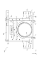
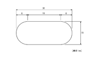
- a U-bolt having a diameter of 9 mm as shown in FIG. 6B is inserted into a bolt hole having a length of 30 mm in the longitudinal direction and a length of 15 mm in the lateral direction as shown in FIG. 6A.
- An extra space of 10.5 mm is formed at both ends of the U bolt in the longitudinal direction, and 3 mm is formed at both ends of the U bolt in the lateral direction.
- An object of the present disclosure made in view of such circumstances is to provide a U-bolt mounting jig capable of mounting U-bolts perpendicularly to a member without increasing the number of parts, and a U-bolt mounting method. be.
- the U-bolt mounting jig is a U-bolt mounting jig for mounting a U-bolt for fixing a pipeline to a member, and is spaced at a predetermined interval so as to be perpendicular to the member.
- the first fixing member and the second fixing member provided so as to face each other and in contact with the side portion of the U bolt, and the first fixing member and the second fixing member so as to be parallel to the member.
- the telescopic member that is fitted and provided so as to be in contact with the central portion of the U bolt is joined to the first fixing member and the second fixing member, and the first fixing member and the second fixing member are sandwiched between the above-mentioned predetermined. It is characterized by including a first joining member and a second joining member for finely adjusting the interval between the two.
- the U-bolt attachment method is a U-bolt attachment method for attaching a U-bolt for fixing a pipeline to a member, and the first fixing member and the second fixing member are perpendicular to the member.
- the step of fixing the first fixing member and the second fixing member to the member at a predetermined interval, and the side portion of the U bolt come into contact with the first fixing member and the second fixing member.
- the U-bolt is perpendicular to the member
- the side portion of the U-bolt is arranged closer to the member than the central portion of the U-bolt and a straight line connecting both ends of the U-bolt. Is meant to be parallel to the surface of the member.
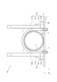
- FIG. 1A is a side view showing an example of the configuration of the U-bolt mounting jig 100.
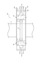
- FIG. 1B is a plan view showing an example of the configuration of the U-bolt mounting jig 100.
- the telescopic member 102 shown in FIG. 1A is omitted.
- the U-bolt attachment jig 100 is a jig for attaching the U-bolt 20 for fixing the pipeline 10 to the attachment member 300 attached to the structure.
- ⁇ member 300 is the surface S 1 is a plane, the conduit 10 may have a stable and capable of supporting a configuration.
- the supporting member 300 is made of, for example, L-shaped steel, flat steel, H-shaped steel, or the like.
- the attachment member 300 is provided with a bolt hole H 1 into which one end of the U bolt 20 is inserted and a bolt hole H 2 into which the other end of the U bolt 20 is inserted.
- the pipeline 10 is a resin or metal pipe, for example, a hard vinyl pipe, an FRP (Fiber Reinforced Plastics) pipe, a steel pipe, a FRPM (Fiberglass Reinforced Plastic Mortar) pipe, or the like.
- the pipeline 10 may have a cylindrical shape, and its configuration is not particularly limited.
- the pipeline 10 may be provided with a joint or the like and may have irregularities on the outside.
- the conduit 10 may be externally provided with a protective piece 11 bonded with an adhesive (see FIG. 1A).
- the conduit 10 When the conduit 10 is provided with the protective piece 11, the conduit 10 can be protected when the conduit 10 is fixed to the mounting member 300 by the U bolt 20.
- FIG. 1 a case where one pipeline 10 is installed on the auxiliary member 300 is taken as an example, but the number of pipelines 10 installed on the auxiliary member 300 is not particularly limited.
- the U-bolt 20 is a single steel material having a curved central portion, a linear shape at the side portions, and a bolt structure at both ends. Both ends of the U bolt 20 are inserted into the bolt holes H 1 and the bolt holes H 2 and screwed into the nut via the conduit 10, the mounting member 300, and the washer. As a result, the pipeline 10 is fixed to the attachment member 300.
- the U-bolt mounting jig 100 includes a fixing member (first fixing member) 101a, a fixing member (second fixing member) 101b, an expansion / contraction member 102, a joining member (first joining member) 103a, and a joining member (second joining).
- a member) 103b, a stop member (first stop member) 104, and a stop member (second stop member) 105 are provided.
- the fixing member 101a includes a fixing portion 1011a, a branch line portion 1012a, and a reinforcing portion 1013a.
- the fixing member 101b includes a fixing portion 1011b, a branch line portion 1012b, and a reinforcing portion 1013b.
- the fixing members 101a and 101b are fixed to the mounting member 300 at intervals L so as to be perpendicular to the mounting member 300.
- the fixing members 101a and 101b have slide grooves Ca and Cb, and are provided so that the slide grooves Ca and Cb are in contact with the side portion of the U bolt 20.
- the interval L is not particularly limited, and is appropriately adjusted by the operator based on, for example, the nominal size of the U bolt 20.
- the side portion of the U bolt 20 is drawn so as to be in contact with the end portions of the fixing members 101a and 101b, but the side portion of the U bolt 20 may be fitted in the slide grooves Ca and Cb.
- the fixing portions 1011a and 1011b are provided with magnets 1014a and 1014b embedded therein.
- the fixing portions 1011a and 1011b can be firmly fixed to the mounting member 300.
- the operator does not have to perform work such as pressing the fixed portions 1011a and 1011b by hand, so that it is possible to avoid the inconvenience that both hands are blocked and the work is difficult.
- the branch line portions 1012a and 1012b are joined to the fixing portions 1011a and 1011b.
- the joining method for joining the branch line portions 1012a and 1012b and the fixing portions 1011a and 1011b is not particularly limited, and for example, they are joined by a known method such as bolt joining, welding joining, and adhesive joining.
- the branch line portion 1012a is provided with a through hole K (see FIG. 1B).
- the branch line portion 1012a is joined to the joining member 103a and the joining member 103b via the stopping member 104 inserted into the through hole K.
- the branch line portion 1012b is provided with a through hole O (see FIG. 1B).
- the branch line portion 1012a is joined to the joining member 103a and the joining member 103b via the stopping member 105 inserted into the through hole O.
- the reinforcing portion 1013a is joined to the fixed portion 1011a and the branch line portion 1012a to reinforce the fixed portion 1011a and the branch line portion 1012a.
- the reinforcing portion 1013b is joined to the fixed portion 1011b and the branch line portion 1012b to reinforce the fixed portion 1011b and the branch line portion 1012b.
- the reinforcing portions 1013a and 1013b have an L-shape, and one side thereof is joined to the fixed portions 1011a and 1011b, and the other side is joined to the branch line portions 1012a and 1012b.
- the joining method in which the reinforcing portion 1013a, the fixing portion 1011a, and the branch line portion 1012a are joined, and the joining method in which the reinforcing portion 1013b, the fixing portion 1011b, and the branch line portion 1012b are joined are not particularly limited, and for example. , Bolt joining, welding joining, adhesive joining, etc., are joined by known methods.
- One end of the telescopic member 102 is fitted into the slide groove Ca provided in the fixing member 101a, and the other end is fitted in the slide groove Cb provided in the fixing member 101b so as to be parallel to the mounting member 300.
- the telescopic member 102 is provided so as to be in contact with the central portion of the U bolt 20.
- the telescopic member 102 can move forward and backward along the slide groove Ca and the slide groove Cb in the Z-axis direction.
- the upper portion of the U bolt 20 can be fixed to the U bolt mounting jig 100 so that the U bolt 20 is perpendicular to the mounting member 300 according to the size (height) of the U bolt 20. ..
- the telescopic member 102 can be expanded and contracted in the X-axis direction according to the distance L between the fixing member 101a and the fixing member 101b.
- the telescopic member 102 is a telescopic pole used in, for example, an antenna.
- the telescopic pole includes a plurality of cylindrical pole members, and each pole member is slidably fitted along the central axis of the cylinder.
- the structure of the telescopic member 102 is not particularly limited.
- the telescopic member 102 preferably has a groove along a curved shape in the central portion of the U bolt 20 at a position in contact with the central portion of the U bolt 20.
- the U bolt 20 can stably maintain a state perpendicular to the mounting member 300. That is, it is possible to prevent the U bolt 20 from being slanted with respect to the mounting member 300.
- the telescopic member 102 preferably includes a magnet 1021 embedded therein. Since the telescopic member 102 includes the magnet 1021, the telescopic member 102 can be firmly fixed to the U-bolt 20, so that the U-bolt 20 can stably maintain a state perpendicular to the mounting member 300. Can be done. That is, it is possible to prevent the U bolt 20 from being slanted with respect to the mounting member 300.
- the joining members 103a and 103b are joined to the fixing members 101a and 101b, and the distance L between the fixing member 101a and the fixing member 101b is finely adjusted.
- the joining members 103a and 103b are, for example, metal fittings.
- the joining member 103a is provided with a plurality of through holes J n (n ⁇ 2) (see FIG. 3F). More specifically, one end of the joint member 103a, the through-holes J 1 is provided on the other end of the joint member 103a, the through-holes J 2 ⁇ J n are provided. The through-holes J 1 is stop member 104 is inserted. A stop member 105 is inserted into the through holes J 2 to J n.
- the joining member 103a is fixed to the fixing member 101a via the stop member 104 inserted into the through hole J 1 and the through hole K, and the stop member 105 inserted into the through holes J 2 to J n and the through hole O. Join with member 101b.
- the joining member 103b is provided with a plurality of through holes M n (n ⁇ 2) (see FIG. 3F). More specifically, one end of the joint member 103b, the through-hole M 1 is provided on the other end of the joint member 103b, the through-hole M 2 ⁇ M n are provided. The through-hole M 1 is stop member 104 is inserted. A stop member 105 is inserted into the through holes M 2 to M n. The joining member 103b is fixed to the fixing member 101a via the stop member 104 inserted into the through hole M 1 and the through hole K, and the stop member 105 inserted into the through holes M 2 to M n and the through hole O. Join with member 101b.
- the plurality of through holes J n and the plurality of through holes M n are provided corresponding to the nominal dimensions of the U bolt 20.
- each through hole is provided so that the distance L between the fixing member 101a and the fixing member 101b matches the size (width) of the U bolt of "65 (M8)".
- the stop member 104 is inserted into the through hole J 1 , the through hole K, and the through hole M 1, and the stop member 105 is inserted into the through hole J 2 , the through hole O, and the through hole M 2.
- the distance L between the fixing member 101b and the fixing member 101b is accurately adjusted according to the width of the U bolt of "65 (M8)".
- each through hole is provided so that the distance L between the fixing member 101a and the fixing member 101b matches the size (width) of the U bolt of "100 (M10)".
- the stop member 104 is inserted into the through hole J 1 , the through hole K, and the through hole M 1, and the stop member 105 is inserted into the through hole J 5 , the through hole O, and the through hole M 5 , so that the fixing member 101a is inserted.
- the distance L between the fixing member 101b and the fixing member 101b is accurately adjusted according to the width of the U bolt of "100 (M10)".
- the joining members 103a and 103b are described with scales corresponding to the nominal dimensions of the U bolt 20.
- a scale “65 (M8)” is described in the vicinity of the through hole J 2 in the joining member 103a and in the vicinity of the through hole M 2 in the joining member 103b.
- a scale "100 (M10)” is described in the vicinity of the through hole J 5 in the joining member 103a and in the vicinity of the through hole M 5 in the joining member 103b.
- the number and positions of through holes provided in the joining members 103a and 103b, or the positions of the scales described in the joining members 103a and 103b can be appropriately changed according to the size of the U bolt 20, and are particularly limited. It's not something.
- the stopping member 104 is a member that is inserted into the through hole J 1 , the through hole K, and the through hole M 1 to join the fixing member 101a and the joining members 103a and 103b.
- the stopping member 104 is, for example, a metal fitting.
- the stopping member 105 is a member that is inserted into the through holes J 2 to J n , the through holes O, and the through holes M 2 to M n to join the fixing member 101b and the joining members 103a and 103b.
- the stopper 105 is, for example, a metal fitting.
- the stop member 104 is inserted into the through hole J 1 , the through hole K, and the through hole M 1 , and the stop member 105 is a through hole. It is inserted into J 2 , the through hole O, and the through hole M 2.
- the stop member 104 is inserted into the through hole J 1 , the through hole K, and the through hole M 1 , and the stop member 105 is a through hole. J 5 , through hole O, and through hole M 5 are inserted.
- the stopping member 104 is not pulled out after being once inserted into the through hole J 1 , the through hole K, and the through hole M 1 by the operator.
- the stopping member 105 may be inserted into the through holes J 2 to J n , the through holes O, and the through holes M 2 to M n by the operator, or the through holes J 2 to J n , the through holes O, And, it is preferable that it is extracted from the through holes M 2 to M n.
- the stop member 104 is fixed to the through hole J 1 , the through hole K, and the through hole M 1
- the stop member 105 is fixed to the through hole J 2 to J n , the through hole O, and the through hole M by the operator.
- junction members 103a, 103b as a fulcrum stop member 104, it is possible to rotate (see arrows in FIG. 1A). That is, the operator can remove the joining members 103a and 103b from the fixing member 101b and attach the joining members 103a and 103b to the fixing member 101b. As a result, the operator can appropriately remove the joining members 103a and 103b from the fixing member 101b and change the distance L between the fixing member 101a and the fixing member 101b according to the size of the U bolt 20.
- the U-bolt mounting jig 100 is fixed to the mounting member 300 at intervals L so as to be perpendicular to the mounting member 300, and is provided so as to be in contact with the side portion of the U-bolt 20.
- the telescopic members 102 which are fitted to the fixing members 101a and 101b so as to be parallel to the members 101a and 101b and the attachment member 300 and are provided so as to be in contact with the central portion of the U bolt, are joined to the fixing members 101a and 101b.
- the joining members 103a and 103b for finely adjusting the interval L are provided. This makes it possible to attach the U bolt 20 perpendicularly to the mounting member 300 without increasing the number of parts.
- the U-bolt mounting jig 100 has high accuracy in determining the distance between the fixing member 101a and the fixing member 101b and the distance between the mounting member 300 and the telescopic member 102 according to the size of the U-bolt. Can be adjusted to. As a result, any kind of U-bolt can be attached vertically to the mounting member 300, so that the operator can install the U-bolt without worrying about the size of the U-bolt. It can be carried out.
- step S101 as shown in FIG. 3A, the operator attaches the fixing members 101a and 101b to the attachment member 300 at intervals L so that the fixing members 101a and 101b are perpendicular to the attachment member 300. Fix it.
- step S102 the operator provides the U-bolt 20 on the auxiliary member 300 so that the side portion of the U-bolt 20 is in contact with the fixing members 101a and 101b.
- one of the side portions of the U bolt 20 may be fitted into the slide groove Ca provided in the fixing member 101a, and the other side portion of the U bolt 20 may be fitted into the slide groove Cb provided in the fixing member 101b. preferable.
- step S103 the operator fits one end of the telescopic member 102 into the slide groove Ca provided in the fixing member 101a so that the telescopic member 102 is parallel to the mounting member 300.
- the other end of the telescopic member 102 is fitted into the slide groove Cb provided in the fixing member 101b.
- the length of the telescopic member 102 is adjusted according to the distance L between the fixing member 102a and the fixing member 102b.
- step S104 the operator slides the telescopic member 102 in the direction of the arrow so that the telescopic member 102 comes into contact with the upper part of the U bolt 20. Since one end of the telescopic member 102 is fitted in the slide groove Ca provided in the fixing member 101a and the other end is fitted in the slide groove Cb provided in the fixing member 101b, the telescopic member 102 is fitted along the slide groove Ca and the slide groove Cb. You can move forward and backward smoothly in the direction of the arrow.
- step S105 the operator inserts the stopping member 104 into the through hole J 1 , the through hole K, and the through hole M 1, and inserts the fixing member 101a and the joining members 103a, 103b.
- the operator inserts the stopping member 105 into the through holes J 2 to J n , the through holes O, and the through holes M 2 to M n to join the fixing member 101b and the joining members 103a and 103b. ..
- the nominal size of the U bolt 20 is "100 (M10)"
- the operator inserts the stop member 104 into the through hole J 1 , the through hole K, and the through hole M 1 , and the stop member 105. Is inserted into the through hole J 5 , the through hole O, and the through hole M 5.
- step S106 as shown in FIG. 3E, the operator, from the surface S 1 and the opposite surface S 2 of ⁇ member 300, via a washer 21a, fastening a nut 22a on one end of the U-bolt 20. Further, the operator, from the surface S 1 and the opposite surface S 2 of ⁇ member 300, via the washer 21b, fastening a nut 22b to the other end of the U-bolt 20. As a result, the pipeline 10 is fixed to the attachment member 300.
- step S101 to step S106 the operator can attach the U bolt 20 perpendicularly to the mounting member 300 without increasing the number of parts.
- step S107 the operator pulls out the stop member 105 from the through holes J 2 to J n , the through holes O, and the through holes M 2 to M n .
- the joining members 103a and 103b are removed from the fixing member 101b.
- the nominal dimension of the U bolt 20 is "100 (M10)"
- the operator pulls out the stop member 105 from the through hole J 5 , the through hole O, and the through hole M 5 .
- step S108 as shown in FIG. 3G, the operator removes the fixing member 101a, the fixing member 101b, and the telescopic member 102 to be joined to the joining members 103a and 103b from the mounting member 300.
- the U-bolt mounting method according to the present embodiment includes the above-mentioned steps S101 to S108. This makes it possible to attach the U bolt 20 perpendicularly to the mounting member 300 without increasing the number of parts.
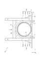
- the U-bolt mounting jig 100A according to the first modification is different from the U-bolt mounting jig 100 according to the present embodiment because the U-bolt mounting jig 100 according to the present embodiment does not have a spirit level and is a fixing member. While the scales are not described on the 101a and 101b and the telescopic member 102, the U-bolt mounting jig 100A according to the first modification is provided with a spirit level, and the scales are described on the fixing members 101a and 101b and the telescopic member 102. It is a point that has been done. Since the other configurations are the same as those of the U-bolt mounting jig 100 according to the present embodiment, duplicate description will be omitted.
- the fixing members 101a and 101b have a scale ⁇ for maintaining the telescopic member 102 horizontally with respect to the mounting member 300.
- the telescopic member 102 can stably maintain a horizontal state with respect to the mounting member 300.
- the telescopic member 102 has a scale ⁇ for maintaining the U-bolt 20 perpendicular to the mounting member 300.
- the U bolt 20 can stably maintain a state perpendicular to the mounting member 300.
- the level 400 is placed on the telescopic member 102 and detects the inclination of the U bolt 20 with respect to the mounting member 300. While visually observing the level 400, the operator finely adjusts the position of the telescopic member 102 so that the telescopic member 102 is in a horizontal state with respect to the mounting member 300. Thereby, the mounting accuracy of the U bolt 20 can be further improved.
- the U-bolt mounting jig 100A according to the first modification can mount the U-bolt 20 perpendicularly to the mounting member 300 without increasing the number of parts.
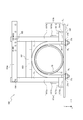
- the U-bolt mounting jig 100B according to the second modification is different from the U-bolt mounting jig 100A according to the first modification, whereas the U-bolt mounting jig 100A according to the first modification does not have a handle.
- the U-bolt mounting jig 100B according to the second modification is provided with a handle. Since the other configurations are the same as those of the U-bolt mounting jig 100A according to the first modification, duplicate description will be omitted.
- the handle 500 is attached to the fixing members 101a and 101b.
- the handle 500 includes fastening portions 500a and 500b.
- the fixing members 101a and 101b include the parts to be fastened 501a and 501b.
- the handles 500 are attached to the fixing members 101a and 101b by joining the fastening portions 500a and 500b provided on the handle 500 and the fastened portions 501a and 501b provided on the fixing members 101a and 101b.
- the handle 500 can rotate around the joint portion where the fastening portions 500a and 500b and the fastened portions 501a and 501b are joined as a fulcrum.
- the fastening portions 500a and 500b may be, for example, a hook or a magnet, but the configuration thereof is not particularly limited.
- the fastened portions 501a and 501b may be, for example, hook stoppers and magnets, but the configuration thereof is not particularly limited.
- the handle 500 preferably has a shape that is easy for the operator to grasp by hand, and is composed of, for example, a rod-shaped member.
- the U-bolt mounting jig 100B according to the second modification can mount the U-bolt 20 perpendicularly to the mounting member 300 without increasing the number of parts.
Landscapes
- Engineering & Computer Science (AREA)
- General Engineering & Computer Science (AREA)
- Mechanical Engineering (AREA)
- Supports For Pipes And Cables (AREA)
- Connection Of Plates (AREA)
- Bridges Or Land Bridges (AREA)
Priority Applications (3)
| Application Number | Priority Date | Filing Date | Title |
|---|---|---|---|
| US17/911,986 US20230114691A1 (en) | 2020-03-18 | 2020-03-18 | U-bolt mounting jig and u-bolt mounting method |
| PCT/JP2020/012103 WO2021186639A1 (ja) | 2020-03-18 | 2020-03-18 | Uボルト取り付け治具、およびuボルト取り付け方法 |
| JP2022507930A JP7324981B2 (ja) | 2020-03-18 | 2020-03-18 | Uボルト取り付け治具、およびuボルト取り付け方法 |
Applications Claiming Priority (1)
| Application Number | Priority Date | Filing Date | Title |
|---|---|---|---|
| PCT/JP2020/012103 WO2021186639A1 (ja) | 2020-03-18 | 2020-03-18 | Uボルト取り付け治具、およびuボルト取り付け方法 |
Publications (1)
| Publication Number | Publication Date |
|---|---|
| WO2021186639A1 true WO2021186639A1 (ja) | 2021-09-23 |
Family
ID=77771731
Family Applications (1)
| Application Number | Title | Priority Date | Filing Date |
|---|---|---|---|
| PCT/JP2020/012103 Ceased WO2021186639A1 (ja) | 2020-03-18 | 2020-03-18 | Uボルト取り付け治具、およびuボルト取り付け方法 |
Country Status (3)
| Country | Link |
|---|---|
| US (1) | US20230114691A1 (https=) |
| JP (1) | JP7324981B2 (https=) |
| WO (1) | WO2021186639A1 (https=) |
Families Citing this family (1)
| Publication number | Priority date | Publication date | Assignee | Title |
|---|---|---|---|---|
| WO2022157961A1 (ja) * | 2021-01-25 | 2022-07-28 | 日本電信電話株式会社 | Uボルト及び施工方法 |
Citations (5)
| Publication number | Priority date | Publication date | Assignee | Title |
|---|---|---|---|---|
| JPS62194985U (https=) * | 1986-05-31 | 1987-12-11 | ||
| JP2010190331A (ja) * | 2009-02-18 | 2010-09-02 | Ntt Facilities Inc | 固定具 |
| KR20120002127U (ko) * | 2010-09-14 | 2012-03-23 | 현대중공업 주식회사 | U볼트 맞춤 작업지그 |
| JP2014118983A (ja) * | 2012-12-13 | 2014-06-30 | Kito Koatsu:Kk | 螺合金具離脱防止具及びクランプ装置 |
| CN204647556U (zh) * | 2015-05-08 | 2015-09-16 | 严梓展 | 一种圆管管道用吊架 |
Family Cites Families (9)
| Publication number | Priority date | Publication date | Assignee | Title |
|---|---|---|---|---|
| US838554A (en) * | 1905-09-18 | 1906-12-18 | August Lasance | Box framer or former. |
| US2390022A (en) * | 1944-07-15 | 1945-11-27 | Sterling A Wood | Hold-down clamp |
| US2538526A (en) * | 1950-06-23 | 1951-01-16 | Kittas William | Adjustable concrete form clamp |
| JPS4895062U (https=) * | 1972-02-15 | 1973-11-13 | ||
| US20080073823A1 (en) * | 2006-09-21 | 2008-03-27 | Tung-Chuan Lin | Clamp structure |
| US8505892B2 (en) * | 2009-10-19 | 2013-08-13 | Charles Seidel | Bar clamp assembly and workpiece support members |
| US8523156B2 (en) * | 2010-06-04 | 2013-09-03 | Tangshan Railway Vehicle Co., Ltd. | Positioning and pressing device, pressing device and tool for auxiliary machining of motor train underframe |
| KR101964212B1 (ko) * | 2016-08-22 | 2019-04-02 | 삼성중공업 주식회사 | 파이프 고정구 |
| US10011003B1 (en) * | 2017-06-23 | 2018-07-03 | Yu-Chun Liu | Pen vice |
-
2020
- 2020-03-18 US US17/911,986 patent/US20230114691A1/en not_active Abandoned
- 2020-03-18 WO PCT/JP2020/012103 patent/WO2021186639A1/ja not_active Ceased
- 2020-03-18 JP JP2022507930A patent/JP7324981B2/ja active Active
Patent Citations (5)
| Publication number | Priority date | Publication date | Assignee | Title |
|---|---|---|---|---|
| JPS62194985U (https=) * | 1986-05-31 | 1987-12-11 | ||
| JP2010190331A (ja) * | 2009-02-18 | 2010-09-02 | Ntt Facilities Inc | 固定具 |
| KR20120002127U (ko) * | 2010-09-14 | 2012-03-23 | 현대중공업 주식회사 | U볼트 맞춤 작업지그 |
| JP2014118983A (ja) * | 2012-12-13 | 2014-06-30 | Kito Koatsu:Kk | 螺合金具離脱防止具及びクランプ装置 |
| CN204647556U (zh) * | 2015-05-08 | 2015-09-16 | 严梓展 | 一种圆管管道用吊架 |
Also Published As
| Publication number | Publication date |
|---|---|
| US20230114691A1 (en) | 2023-04-13 |
| JPWO2021186639A1 (https=) | 2021-09-23 |
| JP7324981B2 (ja) | 2023-08-14 |
Similar Documents
| Publication | Publication Date | Title |
|---|---|---|
| US20180231147A1 (en) | Adjustable support | |
| US8763645B2 (en) | Support system for process piping and method of installation | |
| WO2021186639A1 (ja) | Uボルト取り付け治具、およびuボルト取り付け方法 | |
| CN111037251A (zh) | 自由电子激光装置的加速器腔体装置组装工装及方法 | |
| JP5158476B2 (ja) | 鉄塔の部材取替工法およびその工法で用いられる装置 | |
| JP5041365B2 (ja) | 屋外通信装置の設置構造及び設置方法 | |
| CN103348090B (zh) | 一种用于固定钻机内衬套位置的中心定位器 | |
| CN1336899A (zh) | 用于导轨安装的装置和方法 | |
| CN211076887U (zh) | 一种城建施工用管道夹持工具 | |
| JP6373218B2 (ja) | 高さ調整治具及びスラブの立ち上がり部の形成方法 | |
| CN217398221U (zh) | 一种有限空间吊装大烟道的辅助工具 | |
| JP7425367B2 (ja) | Uボルト取り付け治具、およびuボルト取り付け方法 | |
| JP4523869B2 (ja) | 鋼管基礎杭の柱固定用部材設置方法及び柱固定用部材設置装置 | |
| CN210716309U (zh) | 管道支撑装置 | |
| CN111254967B (zh) | 无线架螺栓定位装置及定位安装方法 | |
| JP6598940B1 (ja) | セパレータ装置 | |
| JP2023061761A (ja) | 建築用パネル取付治具 | |
| JP7043981B2 (ja) | 立金物調整具および中間接続箱の設置方法 | |
| CN219755578U (zh) | 一种快速拼装的风管 | |
| CN216049867U (zh) | 定位装置和定位系统 | |
| CN219386557U (zh) | 一种雨污水管道直线度调整装置 | |
| CN210179870U (zh) | 管路支架组件及空调 | |
| CN113931056B (zh) | 一种梁靴保护装置 | |
| CN220891320U (zh) | 一种穿楼层泵管的洞口固定装置 | |
| JP2000120936A (ja) | 架台用固定補助具 |
Legal Events
| Date | Code | Title | Description |
|---|---|---|---|
| 121 | Ep: the epo has been informed by wipo that ep was designated in this application |
Ref document number: 20925393 Country of ref document: EP Kind code of ref document: A1 |
|
| ENP | Entry into the national phase |
Ref document number: 2022507930 Country of ref document: JP Kind code of ref document: A |
|
| NENP | Non-entry into the national phase |
Ref country code: DE |
|
| 122 | Ep: pct application non-entry in european phase |
Ref document number: 20925393 Country of ref document: EP Kind code of ref document: A1 |