WO2021186601A1 - 二次電池及び電池パック - Google Patents
二次電池及び電池パック Download PDFInfo
- Publication number
- WO2021186601A1 WO2021186601A1 PCT/JP2020/011896 JP2020011896W WO2021186601A1 WO 2021186601 A1 WO2021186601 A1 WO 2021186601A1 JP 2020011896 W JP2020011896 W JP 2020011896W WO 2021186601 A1 WO2021186601 A1 WO 2021186601A1
- Authority
- WO
- WIPO (PCT)
- Prior art keywords
- positive electrode
- negative electrode
- active material
- electrode active
- lithium
- Prior art date
- Legal status (The legal status is an assumption and is not a legal conclusion. Google has not performed a legal analysis and makes no representation as to the accuracy of the status listed.)
- Ceased
Links
Images



Classifications
-
- H—ELECTRICITY
- H01—ELECTRIC ELEMENTS
- H01M—PROCESSES OR MEANS, e.g. BATTERIES, FOR THE DIRECT CONVERSION OF CHEMICAL ENERGY INTO ELECTRICAL ENERGY
- H01M4/00—Electrodes
- H01M4/02—Electrodes composed of, or comprising, active material
- H01M4/36—Selection of substances as active materials, active masses, active liquids
-
- H—ELECTRICITY
- H01—ELECTRIC ELEMENTS
- H01M—PROCESSES OR MEANS, e.g. BATTERIES, FOR THE DIRECT CONVERSION OF CHEMICAL ENERGY INTO ELECTRICAL ENERGY
- H01M4/00—Electrodes
- H01M4/02—Electrodes composed of, or comprising, active material
- H01M4/36—Selection of substances as active materials, active masses, active liquids
- H01M4/48—Selection of substances as active materials, active masses, active liquids of inorganic oxides or hydroxides
- H01M4/485—Selection of substances as active materials, active masses, active liquids of inorganic oxides or hydroxides of mixed oxides or hydroxides for inserting or intercalating light metals, e.g. LiTi2O4 or LiTi2OxFy
-
- H—ELECTRICITY
- H01—ELECTRIC ELEMENTS
- H01M—PROCESSES OR MEANS, e.g. BATTERIES, FOR THE DIRECT CONVERSION OF CHEMICAL ENERGY INTO ELECTRICAL ENERGY
- H01M4/00—Electrodes
- H01M4/02—Electrodes composed of, or comprising, active material
- H01M4/36—Selection of substances as active materials, active masses, active liquids
- H01M4/48—Selection of substances as active materials, active masses, active liquids of inorganic oxides or hydroxides
- H01M4/50—Selection of substances as active materials, active masses, active liquids of inorganic oxides or hydroxides of manganese
- H01M4/505—Selection of substances as active materials, active masses, active liquids of inorganic oxides or hydroxides of manganese of mixed oxides or hydroxides containing manganese for inserting or intercalating light metals, e.g. LiMn2O4 or LiMn2OxFy
-
- H—ELECTRICITY
- H01—ELECTRIC ELEMENTS
- H01M—PROCESSES OR MEANS, e.g. BATTERIES, FOR THE DIRECT CONVERSION OF CHEMICAL ENERGY INTO ELECTRICAL ENERGY
- H01M4/00—Electrodes
- H01M4/02—Electrodes composed of, or comprising, active material
- H01M4/36—Selection of substances as active materials, active masses, active liquids
- H01M4/48—Selection of substances as active materials, active masses, active liquids of inorganic oxides or hydroxides
- H01M4/52—Selection of substances as active materials, active masses, active liquids of inorganic oxides or hydroxides of nickel, cobalt or iron
- H01M4/525—Selection of substances as active materials, active masses, active liquids of inorganic oxides or hydroxides of nickel, cobalt or iron of mixed oxides or hydroxides containing iron, cobalt or nickel for inserting or intercalating light metals, e.g. LiNiO2, LiCoO2 or LiCoOxFy
-
- Y—GENERAL TAGGING OF NEW TECHNOLOGICAL DEVELOPMENTS; GENERAL TAGGING OF CROSS-SECTIONAL TECHNOLOGIES SPANNING OVER SEVERAL SECTIONS OF THE IPC; TECHNICAL SUBJECTS COVERED BY FORMER USPC CROSS-REFERENCE ART COLLECTIONS [XRACs] AND DIGESTS
- Y02—TECHNOLOGIES OR APPLICATIONS FOR MITIGATION OR ADAPTATION AGAINST CLIMATE CHANGE
- Y02E—REDUCTION OF GREENHOUSE GAS [GHG] EMISSIONS, RELATED TO ENERGY GENERATION, TRANSMISSION OR DISTRIBUTION
- Y02E60/00—Enabling technologies; Technologies with a potential or indirect contribution to GHG emissions mitigation
- Y02E60/10—Energy storage using batteries
Definitions
- the embodiment of the present invention relates to a secondary battery and a battery pack.
- Secondary batteries including lithium-ion secondary batteries, are widely used in vehicles such as mobile devices and automobiles, and storage batteries. Secondary batteries are power storage devices whose market size is expected to expand.
- the secondary battery includes electrodes including a positive electrode and a negative electrode.
- the secondary battery may further contain an electrolyte.
- the electrodes of a secondary battery of a certain design include a current collector and an active material-containing layer provided on the main surface of the current collector.
- the active material-containing layer of the electrode can be, for example, a layer composed of active material particles, a conductive agent, and a binder, and can be a porous body capable of holding an electrolyte.
- Lithium-containing manganese oxide is an example of an active material used for the positive electrode of a lithium ion battery or a secondary battery.
- a lithium ion secondary battery using lithium-containing manganese oxide for the positive electrode and lithium titanate for the negative electrode has excellent low-temperature output and longevity performance.
- a secondary battery including a positive electrode, a negative electrode, and a non-aqueous electrolyte and satisfying the following equations (1), (2), and (3) is provided.
- the positive electrode includes a positive electrode active material-containing layer including a positive electrode active material containing a lithium-containing manganese oxide and a lithium-containing nickel cobalt manganese oxide.
- the negative electrode includes a negative electrode active material-containing layer comprising a negative electrode active material containing a lithium titanium oxide and a Li-inserted-desorbed oxide different from the lithium titanium oxide.
- a more preferred range of values of E n is less 96.5% or more 94.0%.
- the values of E n by specifying this range, it is possible to further improve the cycle performance.
- the positive electrode current collector can include a portion that does not support an active material-containing layer on its surface. This portion can serve, for example, as a positive electrode current collector tab.
- the positive electrode may further include a positive electrode current collector tab that is separate from the positive electrode current collector. A separate positive electrode current collector tab can be electrically connected to the positive electrode.
- the basis weight of the positive electrode active material-containing layer that is, the weight per unit area (g / m 2 ) can be, for example, 80 g / m 2 or more and 130 g / m 2 or less.
- the negative electrode current collector can include a portion that does not support a negative electrode active material-containing layer on the surface. This portion can serve as a negative electrode tab. Alternatively, the negative electrode may include a negative electrode tab that is separate from the negative electrode current collector.
- the lithium titanium oxide as the first negative electrode active material includes, for example, lithium titanate having a spinel-type structure (for example, a compound represented by Li 4 + v Ti 5 O 12 ; where v changes with charge and discharge. In value, 0 ⁇ v ⁇ 3), and a compound represented by rams delite type lithium titanate (for example, Li 2 + v Ti 3 O 7 ; where v is a value that changes with charge and discharge, 0 ⁇ v ⁇ . 3) and the like can be mentioned.
- lithium titanate having a spinel-type structure for example, a compound represented by Li 4 + v Ti 5 O 12 ; where v changes with charge and discharge. In value, 0 ⁇ v ⁇ 3
- rams delite type lithium titanate for example, Li 2 + v Ti 3 O 7 ; where v is a value that changes with charge and discharge, 0 ⁇ v ⁇ . 3
- the molar ratio of oxygen is formally shown as 12 for spinel type Li 4 + v Ti 5 O 12 and 7 for rams delite type Li 2 + v Ti 3 O 7 , but these are due to the influence of oxygen non-stoikiometry and the like.
- the value can change. It is desirable that the first titanium-containing oxide has a spinel structure and contains a compound (0 ⁇ v ⁇ 3) represented by Li 4 + v Ti 5 O 12.
- Li insertion-desorption oxides other than the above lithium titanium oxide that is, the second negative electrode active material
- the second negative electrode active material for example, 1.4V (vs.Li / Li +) or more and 2.0V (vs.Li / Li +)
- Oxides having a Li insertion-desorption potential can be used in the following range.
- Specific examples include titanium oxide (titania), hollandite-type titanium composite oxide, lithium titanium composite oxide in which some of the constituent elements of the lithium titanium oxide are replaced with different elements, orthorhombic titanium-containing composite oxidation. Titanium-containing oxides such as materials and niobium titanium composite oxides are included.
- a metal composite oxide containing Ti and at least one element selected from the group consisting of P, V, Sn, Cu, Ni, Nb and Fe can be mentioned.
- the type of the second negative electrode active material can be one type or two or more types.
- monoclinic titanium dioxide (a compound represented by Li u TiO 2 (B); where u is a value that changes depending on the charge / discharge state, 0 ⁇ u ⁇ 1), anatase type titanium dioxide, And rutile type titanium dioxide.
- the rectangular lithium-titanium-containing oxide is represented by the general formula Li 2 + q Na 2-r M1 s Ti 6-t M2 t O 14 + ⁇ , M1 is Cs and / or K, and M2 is Zr, Sn, V. , Nb, Ta, Mo, W, Fe, Co, Mn, and Al.
- the range of each subscript is 0 ⁇ q ⁇ 4, 0 ⁇ r ⁇ 2, 0 ⁇ s ⁇ 2, 0 ⁇ t ⁇ 6, ⁇ 0.5 ⁇ ⁇ ⁇ 0.5, respectively.
- niobium-titanium composite oxide examples include a monoclinic lithium-niobium-titanium-containing oxide and a rectangular Na-containing niobium-titanium composite oxide.
- the monoclinic form lithium niobate titanium-containing oxide is expressed by a general formula Li m Ti 1-n M3 n Nb 2-p M4 p O 7 + ⁇ , M3 is Zr, Si, Sn, Fe, Co, Mn and Ni
- M4 is at least one compound selected from the group consisting of, and M4 being at least one compound selected from the group consisting of V, Nb, Ta, Mo, W and Bi, 0 ⁇ m ⁇ 5,0.
- Examples of the orthorhombic Na-containing niobium-titanium composite oxide include compounds represented by the general formula Li 2 + g Na 2-j M5 h Ti 6-j-k Nb j M6 k O 14 + ⁇ .
- M5 is at least one selected from the group consisting of Cs, K, Sr, Ba and Ca
- M6 is Zr, Sn, V, Ta, Mo, W, Fe, Co, Mn
- Al at least one selected from the group consisting of Al, 0 ⁇ g ⁇ 2, 0 ⁇ h ⁇ 2, 0 ⁇ j ⁇ 2, 0 ⁇ k ⁇ 3, ⁇ 0.5 ⁇ ⁇ ⁇ 0.5. ..
- M6 is at least one selected from the group consisting of Sn, V, Ta, Mo, W, Fe, Co and Mn.
- metal sulfide for example, titanium sulfide such as TiS 2, molybdenum sulfide such as MoS 2, FeS, FeS 2, and Li d FeS 2 (subscript d is 0.9 ⁇ d ⁇ 1.2) of Such as iron sulfide.
- metal nitride include lithium nitride such as lithium cobalt nitride (for example, Li e Co f N, where 0 ⁇ e ⁇ 4 and 0 ⁇ f ⁇ 0.5). ..
- the average particle size of the particles of the first and second negative electrode active materials is preferably 0.8 ⁇ m or more and 1.2 ⁇ m or less.
- the negative electrode active material-containing layer may contain a conductive agent and a binder, if necessary.
- a negative electrode active material, a negative electrode conductive agent, and a binder are suspended in an appropriate solvent, and the obtained slurry is applied to a negative electrode current collector and dried to prepare a negative electrode active material-containing layer. It is produced by pressing.
- the negative electrode active material, the negative electrode conductive agent, and the binder may be formed in pellet form and used as the negative electrode active material-containing layer.
- the thickness of the negative electrode can be in the range of 44 ⁇ m or more and 50 ⁇ m or less.
- the thickness of the negative electrode is the total thickness of the negative electrode active material-containing layer and the negative electrode current collector.
- the total thickness of the two negative electrode active material-containing layers and the negative electrode current collector is the negative electrode thickness.
- Non-aqueous electrolyte examples include a liquid non-aqueous electrolyte prepared by dissolving the electrolyte in a non-aqueous solvent, a gel-like non-aqueous electrolyte obtained by combining a liquid non-aqueous electrolyte and a polymer material, and the like.
- Examples of the electrolyte include lithium perchlorate (LiClO 4 ), lithium hexafluorophosphate (LiPF 6 ), lithium tetrafluoroborate (LiBF 4 ), lithium arsenic hexafluoride (LiAsF 6 ), and difluorophosphate.
- Lithium salts such as lithium (LiPO 2 F 2 ), lithium trifluoromethanesulfonate (LiCF 3 SO 3 ), bistrifluoromethylsulfonylimide lithium [LiN (CF 3 SO 2 ) 2 ], lithium tetrafluorofluoride (LiAlF 4 ) Can be mentioned.
- These electrolytes may be used alone or in admixture of two or more.
- the electrolyte preferably contains lithium hexafluorophosphate.
- the electrolyte is preferably dissolved in a non-aqueous solvent in the range of 0.5 mol / L or more and 2.5 mol / L or less.
- non-aqueous solvent examples include cyclic carbonates such as ethylene carbonate (EC), propylene carbonate (PC) and vinylene carbonate (VC); dimethyl carbonate (DMC), ethyl methyl carbonate (EMC), diethyl carbonate (DEC) and the like.
- cyclic carbonates such as ethylene carbonate (EC), propylene carbonate (PC) and vinylene carbonate (VC); dimethyl carbonate (DMC), ethyl methyl carbonate (EMC), diethyl carbonate (DEC) and the like.
- Chain carbonates cyclic ethers such as tetrahydrofuran (THF), dimethyltetrahydrofuran (2MeTHF); chain ethers such as dimethoxyethane (DME); cyclic esters such as ⁇ -butyrolactone (BL); methyl acetate, ethyl acetate, propionic acid Chain esters such as methyl and ethyl propionate; organic solvents such as acetonitrile (AN); sulfolane (SL) can be mentioned. These organic solvents can be used alone or in the form of a mixture of two or more.
- cyclic ethers such as tetrahydrofuran (THF), dimethyltetrahydrofuran (2MeTHF); chain ethers such as dimethoxyethane (DME); cyclic esters such as ⁇ -butyrolactone (BL); methyl acetate, ethyl acetate, propionic acid Chain esters such as
- polymer material used for the gel-like non-aqueous electrolyte examples include polyvinylidene fluoride (PVdF), polyacrylonitrile (PAN), polyethylene oxide (PEO) and the like.
- the positive electrode and the negative electrode can form an electrode group.
- the positive electrode active material-containing layer and the negative electrode active material-containing layer can face each other via, for example, a separator.
- the electrode group can have various structures.
- the electrode group can have a stack type structure.
- the electrode group having a stack type structure can be obtained, for example, by alternately stacking a plurality of positive electrodes and a plurality of negative electrodes with a separator sandwiched between the positive electrode active material-containing layer and the negative electrode active material-containing layer.
- the electrode group can have a wound structure.
- one separator, one negative electrode, another separator, and one positive electrode are laminated in this order to form a laminated body, and this laminated body is formed. It can be obtained by turning.
- the material of the separator is not particularly limited.
- the separator is preferably electrically insulating.
- As the separator for example, a porous film, a microporous film, a woven fabric, or a non-woven fabric, or a laminate of the same material or a different material among them can be used.
- Examples of the material for forming the separator include polymers such as polyethylene, polypropylene, ethylene-propylene copolymer polymer, ethylene-butene copolymer polymer, polyolefin, cellulose, polyethylene terephthalate, and vinylon.
- the material of the separator may be one kind, or two or more kinds may be used in combination.
- the thickness of the separator is preferably 2 ⁇ m or more and 30 ⁇ m or less.
- the secondary battery according to the embodiment can further include a positive electrode terminal and a negative electrode terminal.
- a part of the positive electrode terminal is electrically connected to a part of the positive electrode, so that the positive electrode terminal can function as a conductor for electrons to move between the positive electrode and the external terminal.
- the positive electrode terminal can be connected to, for example, a positive electrode current collector, particularly a positive electrode tab.
- the negative electrode terminal can act as a conductor for electrons to move between the negative electrode and the external terminal by electrically connecting a part of the negative electrode terminal to a part of the negative electrode.
- the negative electrode terminal can be connected to, for example, a negative electrode current collector, particularly a negative electrode tab.
- the exterior member may be formed of a laminated film or may be composed of a metal container. When using a metal container, the lid can be integral with or separate from the container.
- the wall thickness of the metal container is more preferably 0.5 mm or less and 0.2 mm or less.
- Examples of the shape of the exterior member include a flat type, a square type, a cylindrical type, a coin type, a button type, a sheet type, and a laminated type.
- a large battery mounted on a two-wheeled or four-wheeled automobile may be used.
- the wall thickness of the laminated film exterior member is 0.2 mm or less.
- An example of a laminated film is a multilayer film containing a resin film and a metal layer arranged between the resin films.
- the metal layer is preferably an aluminum foil or an aluminum alloy foil for weight reduction.
- the resin film for example, a polymer material such as polypropylene (PP), polyethylene (PE), nylon, or polyethylene terephthalate (PET) can be used.
- the laminated film can be sealed into the shape of an exterior member by heat fusion.
- the metal container is made of aluminum or aluminum alloy.
- the aluminum alloy an alloy containing elements such as magnesium, zinc, and silicon is preferable.
- the content of transition metals such as iron, copper, nickel and chromium is 100 ppm or less in order to dramatically improve long-term reliability and heat dissipation in a high temperature environment.
- the metal container made of aluminum or an aluminum alloy has an average crystal grain size of 50 ⁇ m or less, more preferably 30 ⁇ m or less, and further preferably 5 ⁇ m or less.
- the average crystal grain size By setting the average crystal grain size to 50 ⁇ m or less, the strength of the metal container made of aluminum or an aluminum alloy can be dramatically increased, and the container can be further thinned. As a result, it is possible to realize a secondary battery suitable for in-vehicle use, which is lightweight, has high output, and has excellent long-term reliability.
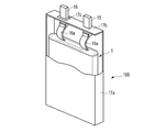
- FIG. 1 is a partially cutaway perspective view of an example of the secondary battery according to the embodiment.
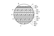
- FIG. 2 is an enlarged cross-sectional view of part A of the secondary battery shown in FIG.
- the secondary battery 100 shown in FIGS. 1 and 2 includes a flat electrode group 1 and an exterior member 7 made of a laminated film.
- the flat electrode group 1 includes a negative electrode 2, a positive electrode 3, and a separator 4.
- the negative electrode 2 and the positive electrode 3 are wound in a flat shape with a separator 4 interposed therebetween.
- the negative electrode 2 includes a negative electrode current collector 2a and a negative electrode active material-containing layer 2b supported on the negative electrode current collector 2a.
- the negative electrode active material-containing layer 2b is placed on the main surface of the two main surfaces of the negative electrode current collector 2a that does not face the positive electrode 3. Not supported.
- the negative electrode active material-containing layer 2b is supported on both main surfaces of the negative electrode current collector.
- the positive electrode 3 includes a positive electrode current collector 3a and a positive electrode active material-containing layer 3b supported on two main surfaces of the positive electrode current collector 3a.
- a band-shaped negative electrode terminal 5 is electrically connected to the negative electrode 2.
- a band-shaped positive electrode terminal 6 is electrically connected to the positive electrode 3.
- the electrode group 1 is housed in the exterior member 7 made of a laminated film in a state where the ends of the negative electrode terminal 5 and the positive electrode terminal 6 extend from the exterior member 7.
- a non-aqueous electrolyte (not shown) is housed in the exterior member 7 made of a laminated film. The non-aqueous electrolyte is impregnated in the electrode group 1.
- the exterior member 7 made of a laminated film is sealed by heat-sealing each of the end portion and the two ends orthogonal to the end portion with the negative electrode terminal 5 and the positive electrode terminal 6 sandwiched between one end portions. ing.
- FIG. 3 is a partially cutaway perspective view showing another example of the battery according to the embodiment.
- the battery 100 shown in FIG. 3 is different from the battery 100 shown in FIGS. 1 and 2 in that the exterior member is composed of the metal container 17a and the sealing plate 17b.
- the flat electrode group 1 includes a negative electrode, a positive electrode, and a separator, similarly to the electrode group 1 in the battery 100 shown in FIGS. 1 and 2. Further, the electrode group 1 has a similar structure between FIGS. 1 and 3. However, in FIG. 3, instead of the negative electrode terminal 5 and the positive electrode terminal 6, the negative electrode lead 15a and the positive electrode lead 16a are electrically connected to the negative electrode and the positive electrode, respectively, as will be described later.
- such an electrode group 1 is housed in a metal container 17a.
- the metal container 17a further contains an electrolyte (not shown).
- the metal container 17a is sealed by a metal sealing plate 17b.
- the metal container 17a and the sealing plate 17b form, for example, an outer can as an outer member.
- One end of the negative electrode lead 15a is electrically connected to the negative electrode current collector, and the other end is electrically connected to the negative electrode terminal 15.
- One end of the positive electrode lead 16a is electrically connected to the positive electrode current collector, and the other end is electrically connected to the positive electrode terminal 16 fixed to the sealing plate 17b.
- the positive electrode terminal 16 is fixed to the sealing plate 17b via an insulating member 17c.
- the positive electrode terminal 16 and the sealing plate 17b are electrically insulated by an insulating member 17c.
- each positive electrode 3 includes a positive electrode current collector 3a and a positive electrode active material-containing layer 3b formed on both sides of the positive electrode current collector 3a. Further, as shown in FIG. 5, the positive electrode current collector 3a includes a portion where the positive electrode active material-containing layer 3b is not formed on the surface thereof. This portion acts as a positive electrode current collecting tab 3c.
- the separator 4 is zigzag.
- a positive electrode 3 or a negative electrode 2 is arranged in a space defined by faces of the zigzag separators 4 facing each other.
- the positive electrode 3 and the negative electrode 2 are laminated so that the positive electrode active material-containing layer 3b and the negative electrode active material-containing layer 2b face each other with the separator 4 interposed therebetween.
- the electrode group 1 is formed.
- the positive electrode current collecting tab 3c of the electrode group 1 extends beyond the respective ends of the positive electrode active material-containing layer 3b and the negative electrode active material-containing layer 2b. As shown in FIG. 5, these positive electrode current collecting tabs 3c are grouped together and connected to the positive electrode terminal 6. Although not shown, the negative electrode current collecting tab of the electrode group 1 also extends beyond the other end of each of the positive electrode active material-containing layer 3b and the negative electrode active material-containing layer 2b. Although these negative electrode current collecting tabs are not shown, they are grouped together and connected to the negative electrode terminal 5 shown in FIG.
- such an electrode group 1 is housed in an exterior member 7 made of an exterior container made of a laminated film.
- the exterior member 7 is formed of an aluminum-containing laminated film composed of an aluminum foil 71 and resin films 72 and 73 formed on both sides thereof.
- the aluminum-containing laminated film forming the exterior member 7 is bent so that the resin film 72 faces inward with the bent portion 7d as a crease, and accommodates the electrode group 1. Further, as shown in FIGS. 4 and 5, in the peripheral edge portion 7b of the exterior member 7, the portions of the resin film 72 facing each other sandwich the positive electrode terminal 6 between them. Similarly, in the peripheral edge portion 7c of the exterior member 7, the portions of the resin film 72 facing each other sandwich the negative electrode terminal 5 between them.
- the positive electrode terminal 6 and the negative electrode terminal 5 extend from the exterior member 7 in opposite directions.
- an insulating film 9 is provided between the positive electrode terminal 6 and the resin film 72 as shown in FIG. Further, at the peripheral edge portion 7b, the positive electrode terminal 6 and the insulating film 9 are heat-sealed, and the resin film 72 and the insulating film 9 are heat-sealed. Similarly, although not shown, an insulating film 9 is also provided between the negative electrode terminal 5 and the resin film 72. Further, in the peripheral edge portion 7c, the negative electrode terminal 5 and the insulating film 9 are heat-sealed, and the resin film 72 and the insulating film 9 are heat-sealed. That is, in the battery 100 shown in FIG. 5, all of the peripheral portions 7a, 7b, and 7c of the exterior member 7 are heat-sealed.
- the exterior member 7 further contains an electrolyte (not shown).
- the electrolyte is impregnated in the electrode group 1.
- a plurality of positive electrode current collecting tabs 3c are grouped in the lowermost layer of the electrode group 1.
- a plurality of negative electrode current collecting tabs are grouped in the lowermost layer of the electrode group 1.
- a plurality of positive electrode current collecting tabs 3c and a plurality of negative electrode current collecting tabs can be combined into one near the middle stage of the electrode group 1 and connected to each of the positive electrode terminal 6 and the negative electrode terminal 5.
- a positive electrode active material-containing layer containing a positive electrode active material containing a lithium-containing manganese oxide and a lithium-containing nickel cobalt manganese oxide, a lithium titanium oxide, and the like Includes a negative electrode active material-containing layer containing a negative electrode active material containing Li insertion-desorbed oxide other than.
- the secondary battery satisfies the following equations (1), (2), and (3): E p> E n (1) E n ⁇ 94% (2) 1.0 ⁇ C p / C n ⁇ 1.2 (3).
- a battery pack is provided.
- This battery pack includes the secondary battery according to the first embodiment.
- the battery pack according to the embodiment may include a plurality of batteries. Multiple batteries can be electrically connected in series or electrically in parallel. Alternatively, a plurality of batteries can be electrically connected in a combination of series and parallel. That is, the battery pack according to the embodiment may include an assembled battery. The number of assembled batteries can be multiple. Multiple battery packs can be electrically connected in series, in parallel, or in a combination of series and parallel.
- FIG. 6 is an exploded perspective view showing an example of the battery pack according to the embodiment.
- FIG. 7 is a block diagram showing an example of the electric circuit of the battery pack shown in FIG.
- the battery pack 20 shown in FIGS. 6 and 7 includes a plurality of cell cells 21.
- the cell 21 may be, for example, an example flat battery 100 according to the embodiment described with reference to FIG.
- the plurality of cells 21 are laminated so that the negative electrode terminals 5 and the positive electrode terminals 6 extending to the outside are aligned in the same direction, and are fastened with the adhesive tape 22 to form the assembled battery 23. These cell cells 21 are electrically connected in series with each other as shown in FIG.
- the printed wiring board 24 is arranged so as to face the side surface on which the negative electrode terminal 5 and the positive electrode terminal 6 of the cell 21 extend. As shown in FIG. 7, the printed wiring board 24 is equipped with a thermistor 25, a protection circuit 26, and a terminal 27 for energizing an external device. An insulating plate (not shown) is attached to the printed wiring board 24 on the surface facing the assembled battery 23 in order to avoid unnecessary connection with the wiring of the assembled battery 23.
- the positive electrode side lead 28 is connected to the positive electrode terminal 6 located at the bottom layer of the assembled battery 23, and the tip thereof is inserted into the positive electrode side connector 29 of the printed wiring board 24 and electrically connected.
- the negative electrode side lead 30 is connected to the negative electrode terminal 5 located on the uppermost layer of the assembled battery 23, and the tip thereof is inserted into the negative electrode side connector 31 of the printed wiring board 24 and electrically connected. These connectors 29 and 31 are connected to the protection circuit 26 through the wirings 32 and 33 formed on the printed wiring board 24.
- the thermistor 25 detects the temperature of the cell 21 and the detection signal is transmitted to the protection circuit 26.
- the protection circuit 26 can cut off the positive side wiring 34a and the negative side wiring 34b between the protection circuit 26 and the energizing terminal 27 to the external device under predetermined conditions.
- An example of the predetermined condition is when the detection temperature of the thermistor 25 becomes equal to or higher than the predetermined temperature. Further, another example of the predetermined condition is the case where an overcharge, an overdischarge, an overcurrent, or the like of the cell 21 is detected.
- the detection of overcharging or the like is performed on the individual cell 21 or the entire assembled battery 23. When detecting the individual cell 21, the battery voltage may be detected, or the positive electrode potential or the negative electrode potential may be detected.
- a lithium electrode used as a reference electrode is inserted into each cell 21.
- a wiring 35 for voltage detection is connected to each of the cell 21. The detection signal is transmitted to the protection circuit 26 through these wires 35.
- Protective sheets 36 made of rubber or resin are arranged on the three side surfaces of the assembled battery 23 except for the side surfaces on which the positive electrode terminal 6 and the negative electrode terminal 5 protrude.
- the assembled battery 23 is housed in the storage container 37 together with the protective sheet 36 and the printed wiring board 24. That is, the protective sheet 36 is arranged on both inner side surfaces along the long side direction and the inner side surface along the short side direction of the storage container 37, and the inside along the other short side direction on the opposite side via the assembled battery 23.
- the printed wiring board 24 is arranged on the side surface.
- the assembled battery 23 is located in a space surrounded by the protective sheet 36 and the printed wiring board 24.
- the lid 38 is attached to the upper surface of the storage container 37.
- a heat-shrinkable tape may be used instead of the adhesive tape 22 to fix the assembled battery 23.
- protective sheets are arranged on both side surfaces of the assembled battery, the heat-shrinkable tape is circulated, and then the heat-shrinkable tape is heat-shrinked to bind the assembled battery.
- the mode of the battery pack according to the embodiment is appropriately changed depending on the application.
- those in which cycle performance in charging / discharging a large current is desired are preferable.
- Specific applications include power supplies for digital cameras, two-wheeled to four-wheeled hybrid electric vehicles, two-wheeled to four-wheeled electric vehicles, and in-vehicle use such as assisted bicycles.
- the use of the battery pack according to the embodiment it is particularly suitable for in-vehicle use.
- the second in the positive electrode active material content in the positive electrode active material the content of the second negative electrode active material of the negative electrode active material in the charge-discharge efficiency E p of the positive electrode, the negative electrode charge-discharge efficiency E n, the positive electrode
- a method for measuring the open circuit voltage, the thickness of the positive electrode and the negative electrode, and the density will be described. First, a method of taking out the electrodes will be described.
- the battery is completely discharged and the charged state (SOC) is set to 0%. For example, it discharges to a battery voltage of 1.8 V with a current value of 1 C.
- This battery is disassembled and the electrode group is taken out. Cut out about 2 cm square each of the positive electrode and the negative electrode from the electrode group. Each of the cut electrodes is immersed in 50 cc (cm 3 ) of ethyl methyl carbonate and left for 1 hour. Then, in order to dry the electrode, it is vacuum dried for 1 hour to obtain a measurement sample. The operations up to this point are performed in a glove box with an argon atmosphere.
- 1C is a current value capable of charging and discharging the nominal capacity of the secondary battery in one hour.
- X-ray source Cu target Output: 45kV, 200mA Solar slit: 5 ° for both incident and light reception Step width: 0.02 deg Scan speed: 20 deg / min
- Semiconductor detector D / teX Ultra 250
- Sample plate holder Flat glass sample plate holder (thickness 0.5 mm) Measurement range: Range of 10 ° ⁇ 2 ⁇ ⁇ 90 °.
Landscapes
- Chemical & Material Sciences (AREA)
- Chemical Kinetics & Catalysis (AREA)
- Electrochemistry (AREA)
- General Chemical & Material Sciences (AREA)
- Inorganic Chemistry (AREA)
- Battery Electrode And Active Subsutance (AREA)
- Secondary Cells (AREA)
Abstract
実施形態によれば、正極と、負極と、非水電解質とを含み、かつ下記(1)式~(3)式を満たす、二次電池が提供される。正極は、リチウム含有マンガン酸化物とリチウム含有ニッケルコバルトマンガン酸化物とを含む正極活物質含有層を含む。負極は、リチウムチタン酸化物とこのリチウムチタン酸化物とは異なるLi挿入-脱離酸化物とを含む負極活物質含有層を含む。 Ep>En (1) En≧94% (2) 1.0≦Cp/Cn≦1.2 (3) 但し、Epは3.0V以上4.25V(vs.Li/Li+)以下の範囲における正極の充放電効率、Enは1.4V以上2.0V(vs.Li/Li+)以下の範囲における負極の充放電効率、Cpは正極の充放電範囲が3.0V以上4.25V(vs.Li/Li+)以下である時の単位面積当たりの充電容量、Cnは負極の充放電範囲が1.4V以上2.0V(vs.Li/Li+)以下である時の単位面積当たりの充電容量である。
Description
本発明の実施形態は、二次電池及び電池パックに関する。
リチウムイオン二次電池を含め、二次電池は、携帯機器、自動車などの車両や蓄電池などに広く用いられている。二次電池は、市場規模の拡大が見込まれている蓄電デバイスである。
二次電池は、正極及び負極を含む電極を含んでいる。二次電池は、電解質をさらに含み得る。ある設計の二次電池の電極は、集電体と、この集電体の主面上に設けられた活物質含有層とを備える。電極の活物質含有層は、例えば、活物質粒子、導電剤、及びバインダにより構成される層であり得、電解質を保持可能な多孔体であり得る。
リチウムイオン電池または二次電池の正極に用いられる一例の活物質として、リチウム含有マンガン酸化物がある。正極にリチウム含有マンガン酸化物を用い、負極にチタン酸リチウムを用いたリチウムイオン二次電池は、低温出力や寿命性能に優れる。
充放電サイクル寿命に優れた二次電池、及びこの電池を具備する電池パックを提供することを目的とする。
実施形態によれば、正極と、負極と、非水電解質とを含み、かつ下記(1)式、下記(2)式、及び下記(3)式を満たす、二次電池が提供される。正極は、リチウム含有マンガン酸化物とリチウム含有ニッケルコバルトマンガン酸化物とを含む正極活物質を備える正極活物質含有層を含む。負極は、リチウムチタン酸化物とこのリチウムチタン酸化物とは異なるLi挿入-脱離酸化物とを含む負極活物質を備える負極活物質含有層を含む。
Ep>En (1)
En≧94% (2)
1.0≦Cp/Cn≦1.2 (3)
但し、Epは3.0V(vs.Li/Li+)以上4.25V(vs.Li/Li+)以下の充放電範囲における正極の充放電効率、Enは1.4V(vs.Li/Li+)以上2.0V(vs.Li/Li+)以下の充放電範囲における負極の充放電効率、Cpは正極の充放電範囲が3.0V(vs.Li/Li+)以上4.25V(vs.Li/Li+)以下である時の単位面積当たりの充電容量(mAh/m2)、Cnは負極の充放電範囲が1.4V(vs.Li/Li+)以上2.0V(vs.Li/Li+)以下である時の単位面積当たりの充電容量(mAh/m2)である。
En≧94% (2)
1.0≦Cp/Cn≦1.2 (3)
但し、Epは3.0V(vs.Li/Li+)以上4.25V(vs.Li/Li+)以下の充放電範囲における正極の充放電効率、Enは1.4V(vs.Li/Li+)以上2.0V(vs.Li/Li+)以下の充放電範囲における負極の充放電効率、Cpは正極の充放電範囲が3.0V(vs.Li/Li+)以上4.25V(vs.Li/Li+)以下である時の単位面積当たりの充電容量(mAh/m2)、Cnは負極の充放電範囲が1.4V(vs.Li/Li+)以上2.0V(vs.Li/Li+)以下である時の単位面積当たりの充電容量(mAh/m2)である。
他の実施形態によれば、上記実施形態に係る二次電池を含む電池パックが提供される。
正極にリチウム含有マンガン酸化物を用い、負極にチタン酸リチウムを用いたリチウムイオン二次電池は、低温出力や寿命性能に優れる。一方で、このような電池ではガス発生が生じるという課題があった。また、正極からのMn溶出による電池性能の劣化という課題があった。
ガス発生に対する対策として、層状構造を持つ活物質を加えることができる。そういった活物質の中でもリチウム含有コバルト酸化物はガス吸着材の役割を果たすため、リチウム含有マンガン酸化物とリチウム含有コバルト酸化物の双方を正極活物質に用いることでガス発生量が低減する。
しかし、リチウム含有コバルト酸化物には、高電位での劣化が著しいという課題がある。そこで、リチウム含有コバルト酸化物の代替としてリチウム含有ニッケルコバルトマンガン酸化物を用いることが検討されている。リチウム含有ニッケルコバルトマンガン酸化物は、高電位に対する耐性がある。しかしリチウム含有ニッケルコバルトマンガン酸化物は、リチウムイオンが挿入-脱離される際の膨張収縮が大きく、サイクル寿命性能に課題がある。さらに、リチウム含有ニッケルコバルトマンガン酸化物は、作動電位が低い。そのうえ、3.6V(vs.Li/Li+)以下の電位ではリチウム含有ニッケルコバルトマンガン酸化物のサイクル寿命性能が劣化しやすい傾向が見られる。
以下に、実施の形態について図面を参照しながら説明する。なお、実施の形態を通して共通の構成には同一の符号を付すものとし、重複する説明は省略する。また、各図は実施の形態の説明とその理解とを促すための模式図であり、その形状や寸法、比などは実際の装置と異なる個所があるが、これらは以下の説明と公知の技術とを参酌して、適宜設計変更することができる。
(第1の実施形態)
第1の実施形態によると、正極活物質含有層を含む正極と、負極活物質含有層を含む負極と、非水電解質とを含む二次電池が提供される。正極活物質含有層は、第1の正極活物質としてのリチウム含有マンガン酸化物と第2の正極活物質としてのリチウム含有ニッケルコバルトマンガン酸化物とを含む正極活物質を含む。負極活物質含有層は、第1の負極活物質としてのリチウムチタン酸化物を含むとともに、そのリチウムチタン酸化物とは異なるLi挿入-脱離酸化物を第2の負極活物質として含む。二次電池は、下記(1)式、(2)式、及び(3)式を満たす。
第1の実施形態によると、正極活物質含有層を含む正極と、負極活物質含有層を含む負極と、非水電解質とを含む二次電池が提供される。正極活物質含有層は、第1の正極活物質としてのリチウム含有マンガン酸化物と第2の正極活物質としてのリチウム含有ニッケルコバルトマンガン酸化物とを含む正極活物質を含む。負極活物質含有層は、第1の負極活物質としてのリチウムチタン酸化物を含むとともに、そのリチウムチタン酸化物とは異なるLi挿入-脱離酸化物を第2の負極活物質として含む。二次電池は、下記(1)式、(2)式、及び(3)式を満たす。
Ep>En (1)
En≧94% (2)
1.0≦Cp/Cn≦1.2 (3)。
En≧94% (2)
1.0≦Cp/Cn≦1.2 (3)。
ここで、Epは3.0V(vs.Li/Li+)以上4.25V(vs.Li/Li+)以下の充放電範囲における正極の充放電効率である。Enは1.4V(vs.Li/Li+)以上2.0V(vs.Li/Li+)以下の充放電範囲における負極の充放電効率である。Cpは正極の充放電範囲が3.0V(vs.Li/Li+)以上4.25V(vs.Li/Li+)以下である時の単位面積当たりの充電容量(mAh/m2)である。Cnは負極の充放電範囲が1.4V(vs.Li/Li+)以上2.0V(vs.Li/Li+)以下である時の単位面積当たりの充電容量(mAh/m2)である。
二次電池は、例えば、リチウムイオン電池であり得る。二次電池の具体例として、非水電解質二次電池を挙げることができる。非水電解質二次電池を、単に非水電解質電池と呼ぶことがある。
Ep及びEnを(1)式の関係および(2)式の範囲に特定する理由と、Cnに対するCpの比(Cp/Cn)を(3)式の範囲に特定する理由とを説明する。
上述した(1)式(Ep>En)を満たしているということは、正極の充放電効率と比較して負極の充放電効率が低いことを示す。(2)式(En≧94%)を満たしているということは、負極の充放電効率が適度に高く、低すぎないことを示す。これら(1)式および(2)式の両方を満たしているということは、正極と負極との間で充放電のバランスが適切に調整されていることを示す。このような状態にある電池では、充電状態(State Of Charge;SOC)が0%であるときの正極電位が下がりにくい。具体例として、上記第1正極活物質と第2正極活物質とを組み合わせた系の正極を含む二次電池において、当該電池を0.2Cの電流値で電池電圧1.8Vまで放電した時の正極の開回路電圧が、3.6V(vs.Li/Li+)以上3.9V(vs.Li/Li+)以下の範囲内にあり得る。放電状態における正極電位が下がりにくいため、電池のサイクル寿命性能を大きく向上させることが可能である。また、正極と比べて負極の充放電効率が下がっていることで、負極活物質についての二相共存反応領域の使用範囲が狭められるため、サイクル寿命性能が改善する。
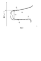
図8は、実施形態に係る電池の充放電曲線の一例を示すグラフである。図8のグラフにおける横軸は電池の容量(Ah)、縦軸は電極電位(vs.Li/Li+)を示す。当該グラフは、正極の充電曲線83及び放電曲線93、並びに負極の充電曲線82及び放電曲線92を示す。正極の充電曲線83と放電曲線93のそれぞれの横軸方向への長さの差は小さく、正極の充放電効率Epが高いことがわかる。他方、負極の充電曲線82と放電曲線92との間の横軸方向の長さの差は正極についてのそれよりも大きく、負極の充放電効率Enの方が正極の充放電効率Epよりも低いことがわかる。負極の充放電効率の方が低いため、放電終止電圧に到達する間際に、正極電位が大きく低下する前に負極電位が上昇する。そのため、放電に伴って正極電位が大幅に低下する前に、電池の放電終止電圧、例えば、1.8Vの放電終止電圧に到達できる。このように、放電状態(例えば、SOC = 0%の時)の正極電位P0が低くならず、正極電位が極端に下がりきらない状態で放電を終了できる。
Enの値のより好ましい範囲は94.0%以上96.5%以下である。Enの値をこの範囲に特定することにより、サイクル性能をより向上することができる。
上記(3)式(1.0≦Cp/Cn≦1.2)を満たしているということは、正極容量が負極容量と比較して同等から1.2倍程度であることを示す。正極容量が負極容量以上であることで、正極電位が下がることを低減できる。負極容量に対する正極容量の比(Cp/Cn)が1.2以下であると、高いエネルギー密度を確保できる。
以上説明した理由により、Ep及びEnを(1)式の関係および(2)式の範囲に特定すると共に、CpとCnとの比を(3式)の範囲に特定することにより、サイクル性能を向上することが可能である。
第1、第2の正極活物質のそれぞれの組成、正極活物質中の第1、第2の正極活物質の配合割合、第1、第2の負極活物質のそれぞれの組成、負極活物質中の第1、第2の負極活物質の配合割合、正極活物質含有層の厚み、負極活物質含有層の厚み、並びに組立後の電池に対するエージング条件を含め、電池製造の際の設計を適宜組合わせることで、(1)式、(2)式、及び(3)式の全てを満たす二次電池を得ることができる。後段の実施例にて、具体例を示す。例えば、Epに対しては、正極活物質中の第2の正極活物質の重量比率の影響が大きい。Enに対しては、負極活物質中の第2の負極活物質の重量比率の影響が大きい。
リチウム含有マンガン酸化物(第1の正極活物質)とリチウム含有ニッケルコバルトマンガン酸化物(第2の正極活物質;以後、NCM)とを併せて用いた正極と、例えば、スピネル構造を有しLi4Ti5O12で表されるチタン酸リチウム等のリチウムチタン酸化物を用いた負極とを組み合わせた系の電池では、正極に用いるNCMの比率が低いと負極で発生する還元ガスの抑制が少ない。他方、NCMは作動電位が低く、また初期充放電効率が低い。そのため、正極に用いるNCMの比率が高いと、正極の作動電位が下がる。さらに、NCMの比率が高いと正極初期の充放電効率が低いため、SOC = 0%である時の正極電位が低くなり得る。即ち、正極中のNCM比率が高いほど正極の作動範囲が低い電位にまで広がり、NCMのサイクル寿命の劣化が進む電位が充放電範囲に含まれやすくなる。このように、高いNCM比率は、正極の劣化を加速させる要因になり、その影響により電池のサイクル寿命が短くなり得る。
正極活物質中の第2の正極活物質の含有量が2wt%以上20wt%以下であることが好ましい。正極活物質のうち第2の正極活物質(NCM)の含有量が2wt%以上であると、負極における非水電解質の還元分解で発生するガスを正極で吸収する効果を発揮できる。第2の正極活物質の含有量が20wt%以下であると、正極の作動電位を十分に高く維持できる。また、正極の充放電効率を良好に保てる。正極活物質中の第2の正極活物質の含有量のより好ましい範囲は3wt%以上20wt%以下である。
第1の負極活物質としては、例えば、上述したスピネル構造のチタン酸リチウム(Li4Ti5O12)を挙げることができるが、当該チタン酸リチウムは、充放電効率が高いうえ、充放電の際のリチウムイオンの挿入-脱離に伴う膨張収縮が極めて少ない。第1の負極活物質とともに、第1の負極活物質のリチウムチタン酸化物とは異なるLi挿入-脱離酸化物を第2の負極活物質として併用することで、サイクル寿命性能を改善することができる。ここでいう上記リチウムチタン酸化物とは異なるLi挿入-脱離酸化物(第2の負極活物質)とは、正負極間の電荷のキャリアイオンであるLiイオンの挿入および脱離が可能な金属酸化物や金属含有複合酸化物等の酸化物のうち、第1の負極活物質としての上記リチウムチタン酸化物以外の酸化物を含む。具体例としてニオブチタン複合酸化物および酸化チタンからなる群より選択される1以上のLi挿入-脱離酸化物を挙げることができる。上記チタン酸リチウム等のリチウムチタン酸化物(第1の負極活物質)を単独で用いた負極では放電時に、高い充放電効率に起因して、当該酸化物内部のリチウム拡散があまり良くない放電末期を経由する。上記第1の負極活物質と共に上記の第2の負極活物質を用いた負極では、第1の負極活物質を単独で用いた負極と比較して充放電効率が下がっている。それにより、第1の負極活物質の放電末期を経由することを避けることができる。
他方、第2の負極活物質の割合が多くなると、充放電の際の負極の膨張収縮に起因して、サイクル寿命性能が低下し得る。例えば、ニオブチタン複合酸化物を単独で用いた負極では充放電時における体積膨張収縮が大きいため、チタン酸リチウムを用いた負極と比較してサイクル性能が低くなりがちである。
これらのことから、負極活物質のうち第2の負極活物質の含有量が3wt%以上30wt%以下であることが好ましい。負極活物質中の第2の負極活物質の含有量のより好ましい範囲は3wt%以上20wt%以下である。
二次電池を0.2Cで1.8Vまで放電した時の正極の開回路電圧を3.6V(vs.Li/Li+)以上3.9V(vs.Li/Li+)以下にすることが望ましい。このように放電した二次電池は、0%の充電状態(SOC)にあり得る。開回路電圧を3.6V(vs.Li/Li+)以上にすることにより、正極電位が下がりにくくなるため正極の劣化を抑制することができる。また、開回路電圧を3.9V(vs.Li/Li+)以下にすることにより、正極の開回路電圧が3.9V(vs.Li/Li+)よりも高い範囲を充放電領域として使用することができるため、高容量を得ることができる。二次電池を0.2Cで1.8Vまで放電した時の正極の開回路電圧のより好ましい範囲は、3.69V(vs.Li/Li+)以上3.80V(vs.Li/Li+)以下である。
以下、実施形態に係る電池を詳細に説明する。
(1)正極
正極は、正極集電体と、正極集電体の一方または両方の面に担持される正極活物質含有層とを含む。
正極は、正極集電体と、正極集電体の一方または両方の面に担持される正極活物質含有層とを含む。
正極活物質含有層は、第1の正極活物質としてのリチウム含有マンガン酸化物と第2の正極活物質としてのリチウム含有ニッケルコバルトマンガン酸化物とを含む。
リチウム含有マンガン酸化物は、例えば、化学式LiMn2-xMxO4で表される化合物であるスピネル型マンガン酸リチウムを含む。ここでMは、Mg、Ti、Cr、Fe、Co、Zn、Al、およびGaからなる群より選択される少なくとも一つである。添字xは、0.22以上0.7以下である。以降、リチウム含有マンガン酸化物を“LMO”と表記することがある。
リチウム含有ニッケルコバルトマンガン酸化物は、例えば、LiNi1-y-zCoyMnzO2(ここで、0<y<1、0<z<1及び0<y+z<1)を含む。
正極活物質は、第1、第2の正極活物質以外の他の正極活物質を含んでいても良い。他の正極活物質は、例えば、リチウム含有コバルト酸化物、リチウム含有ニッケルコバルト複合酸化物、及びリチウム含有マンガンコバルト酸化物からなる群より選択される1以上の化合物を含むことができる。リチウム含有コバルト酸化物の例は、LiwCoO2を含む。当該化学式LiwCoO2における添字wの範囲は、0<w≦1である。リチウムニッケルコバルト複合酸化物の例は、LiNi1-yCoyO2(ここで、0<y<1)を含む。リチウムマンガンコバルト酸化物の例は、LiMnyCo1-yO2(ここで、0<y<1)を含む。
正極活物質は、例えば、粒子状である。粒子状である場合には、正極活物質は、一次粒子であってもよいし、又は一次粒子の凝集した二次粒子であってもよい。
第1の正極活物質の粒子の平均粒子径は8.0μm以上11.0μm以下であることが好ましい。また、第2の正極活物質の粒子の平均粒子径は5.2μm以上6.8μm以下であることが好ましい。
正極活物質含有層は、必要に応じて結着剤及び導電剤を含むことができる。
結着剤は、活物質と導電剤とを結着させ得る。結着剤としては、例えば、ポリテトラフルオロエチレン(PTFE)、ポリフッ化ビニリデン(PVdF)、又はフッ素系ゴムが含まれる。使用する結着剤の種類は、1種又は2種以上にすることができる。
導電剤は、電子導電性を高め、集電体との接触抵抗を抑え得る。導電剤としては、例えば、アセチレンブラック、カーボンブラック、黒鉛、カーボンナノファイバー又はカーボンナノチューブなどの炭素材料が含まれる。使用する導電剤の種類は、1種又は2種以上にすることができる。
正極活物質、導電剤及び結着剤の配合比は、正極活物質80重量%~95重量%、導電剤3重量%~18重量%、結着剤2重量%~7重量%の範囲にすることが好ましい。
集電体としては、例えば、電気伝導性の高い材料を含むシートを使用することができる。例えば、集電体としては、アルミニウム箔またはアルミニウム合金箔を使用することができる。アルミニウム箔又はアルミニウム合金箔を使用する場合、その厚さは、20μm以下であることが好ましい。アルミニウム合金箔は、マグネシウム(Mg)、チタニウム(Ti)、亜鉛(Zn)、マンガン(Mn)、及びケイ素(Si)等を含むことができる。また、アルミニウム合金箔は、他の遷移金属を含んでいてもよい。アルミニウム合金箔における遷移金属の含有量は、1質量%以下であることが好ましい。遷移金属としては、例えば、鉄(Fe)、銅(Cu)、ニッケル(Ni)、又はクロム(Cr)を挙げることができる。集電体は、アルミニウム箔、又は、アルミニウムと、Mg、Ti、Zn、Mn、Fe、Cu、及びSiから成る群より選択される一以上の元素とを含むアルミニウム合金箔であることが好ましい。
正極集電体は、その表面に活物質含有層を担持していない部分を含むことができる。この部分は、例えば、正極集電タブとして働くことができる。或いは、正極は、正極集電体とは別体の正極集電タブをさらに具備することもできる。別体の正極集電タブは、正極に電気的に接続され得る。
正極の厚さは、80μm以下にすることが望ましい。ここで、正極の厚さは、正極活物質含有層と正極集電体の合計厚さである。正極集電体の両面に正極活物質含有層が担持されている場合には、2つの正極活物質含有層と正極集電体の合計厚さが正極厚さである。正極の厚さを80μm以下にすることにより、正極の抵抗を低くすることができるため、正極にかかる過電圧を小さくすることができる。それにより、放電末期の正極電位の低下を抑制することができるため、正極の過放電による劣化を抑えることができる。実用的な電池容量を確保するため、正極の厚さは、65μm以上にすることが望ましい。
正極活物質含有層の密度は、2.5g/cm3以上3.1g/cm3以下にすることが好ましい。これにより、正極の厚さが例えば80μm以下と薄くても、実用に耐え得る正極容量を確保することができる。
正極活物質含有層の目付、すなわち単位面積当たりの重量(g/m2)は、例えば、80g/m2以上130g/m2以下にすることができる。
正極の製造では、まず、例えば正極活物質、正極導電剤及び結着剤を適当な溶媒に懸濁させ、得られたスラリーを正極集電体に塗布して乾燥させることにより正極活物質含有層を作製した後、プレスを施す。その他、正極活物質、正極導電剤及び結着剤をペレット状に形成し、正極活物質含有層として用いてもよい。
(2)負極
負極は、負極集電体と、負極集電体の一方または両方の面に担持される負極活物質含有層とを含む。負極活物質含有層は、第1の負極活物質および第2の負極活物質としてリチウムチタン酸化物およびそれとは異なるLi挿入-脱離酸化物をそれぞれ含む。
負極は、負極集電体と、負極集電体の一方または両方の面に担持される負極活物質含有層とを含む。負極活物質含有層は、第1の負極活物質および第2の負極活物質としてリチウムチタン酸化物およびそれとは異なるLi挿入-脱離酸化物をそれぞれ含む。
負極集電体は、表面に負極活物質含有層を担持していない部分を含むことができる。この部分は、負極タブとして働くことができる。或いは、負極は、負極集電体とは別体の負極タブを含むこともできる。
第1の負極活物質としてのリチウムチタン酸化物には、例えば、スピネル型構造を有するチタン酸リチウム(例えば、Li4+vTi5O12で表される化合物;ここで、vは充放電により変化する値で、0≦v≦3)、及びラムスデライト型のチタン酸リチウム(例えば、Li2+vTi3O7で表される化合物;ここで、vは充放電により変化する値で、0≦v≦3)等を挙げることができる。一方、酸素のモル比についてはスピネル型Li4+vTi5O12では12、ラムスデライト型Li2+vTi3O7では7と形式的には示しているが、酸素ノンストイキオメトリーなどの影響によってこれらの値は変化し得る。第1チタン含有酸化物がスピネル構造を有しLi4+vTi5O12で表される化合物(0≦v≦3)を含むことが望ましい。
上記リチウムチタン酸化物以外のLi挿入-脱離酸化物、つまり第2の負極活物質には、例えば、1.4V(vs.Li/Li+)以上2.0V(vs.Li/Li+)以下の範囲においてLi挿入-脱離の電位を有する酸化物を用いることができる。具体例として、酸化チタン(チタニア)、ホランダイト型チタン複合酸化物、上記リチウムチタン酸化物の構成元素の一部を異種元素で置換したリチウムチタン複合酸化物、直方晶型(orthorhombic)チタン含有複合酸化物、ニオブチタン複合酸化物等のチタン含有酸化物が含まれる。他の例として、TiとP、V、Sn、Cu、Ni、Nb及びFeからなる群より選択される少なくとも1種類の元素とを含有する金属複合酸化物を挙げることができる。第2の負極活物質の種類は1種類または2種類以上にすることができる。
酸化チタンとしては、単斜晶型二酸化チタン(LiuTiO2(B)で表される化合物;ここでuは充放電状態により変化する値で、0≦u≦1)、アナターゼ型二酸化チタン、及びルチル型二酸化チタンが挙げられる。
直方晶型リチウムチタン含有酸化物としては、一般式Li2+qNa2-rM1sTi6-tM2tO14+δで表され、M1はCs及び/又はKであり、M2はZr,Sn,V,Nb,Ta,Mo,W,Fe,Co,Mn,及びAlのうち少なくとも1つを含む化合物が挙げられる。各々の添字の範囲はそれぞれ、0≦q≦4、0≦r≦2、0≦s≦2、0≦t<6、-0.5≦δ≦0.5である。
ニオブチタン複合酸化物としては、単斜晶型リチウムニオブチタン含有酸化物および直方晶型Na含有ニオブチタン複合酸化物を挙げることができる。単斜晶型リチウムニオブチタン含有酸化物としては、一般式LimTi1-nM3nNb2-pM4pO7+σで表され、M3はZr,Si,Sn,Fe,Co,Mn及びNiから成る群から選択される少なくとも1つであり、M4はV,Nb,Ta,Mo,W及びBiから成る群から選択される少なくとも1つである化合物が挙げられ、0≦m≦5、0≦n<1、0≦p<2、-0.3≦σ≦0.3である。直方晶型Na含有ニオブチタン複合酸化物としては、一般式Li2+gNa2-jM5hTi6-j-kNbjM6kO14+δで表される化合物を挙げることができる。一般式において、M5は、Cs、K、Sr、Ba及びCaからなる群より選択される少なくとも1つであり、M6は、Zr,Sn,V,Ta,Mo,W,Fe,Co,Mn,及びAlからなる群より選択される少なくとも1つであり0≦g<2、0≦h<2、0<j<2、0≦k<3、-0.5≦δ≦0.5である。M6が、Sn,V,Ta,Mo,W,Fe,Co及びMnからなる群より選択される少なくとも1つであることが好ましい。
負極活物質含有層は、第2負極活物質としてニオブチタン複合酸化物および酸化チタンからなる群より選択される1以上を含み得る。特に、第2負極活物質は、例えば、単斜晶型リチウムニオブ含有酸化物および/又は単斜晶型二酸化チタンであり得る。
負極活物質は、第1、第2の負極活物質以外の他の負極活物質を含んでいても良い。他の負極活物質は、例えば、金属、金属合金、金属硫化物、金属窒化物、黒鉛質材料、炭素質材料を含む。金属としては、例えば、アルミニウムやリチウム等を挙げることができる。金属合金としては、例えば、アルミニウム合金、マグネシウム合金、リチウム合金等を挙げることができる。金属以外にも、例えば、シリコンのような半金属を負極活物質として用いることができる。金属硫化物としては、例えば、TiS2のような硫化チタン、MoS2のような硫化モリブデン、FeS、FeS2、及びLidFeS2(添字dは、0.9≦d≦1.2)のような硫化鉄が挙げられる。金属窒化物としては、例えば、リチウムコバルト窒化物(例えば、LieCofN、ここで、0<e<4であり、0<f<0.5である)などのリチウム窒化物が挙げられる。黒鉛質材料および炭素質材料としては、例えば、黒鉛(例えば、天然黒鉛、又は人造黒鉛)、コークス、気相成長炭素繊維、メソフェーズピッチ系炭素繊維、球状炭素、樹脂焼成炭素を挙げることができる。
負極活物質は、例えば、粒子状である。粒子状である場合には、負極活物質は、一次粒子であってもよいし、又は一次粒子の凝集した二次粒子であってもよい。
第1、第2負極活物質の粒子の平均粒子径は0.8μm以上1.2μm以下であることが好ましい。
負極活物質含有層は、必要に応じて導電剤及び結着剤を含んでいても良い。
結着剤は、例えばポリテトラフルオロエチレン(PTFE)、ポリフッ化ビニリデン(PVdF)、フッ素系ゴム、スチレンブタジエンゴム(SBR)、カルボキシメチルセルロース(CMC)、ポリイミド、ポリアミドなどを挙げることができる。結着剤の種類は1種類または2種類以上にすることができる。
負極導電剤としては、例えばアセチレンブラック、ケッチェンブラックなどのカーボンブラック、黒鉛、炭素繊維、カーボンナノチューブ、フラーレンなどを挙げることができる。導電剤の種類は1種類または2種類以上にすることができる。
負極活物質含有層における負極活物質、導電剤および結着剤の配合割合は、負極活物質70重量%以上96重量%以下、導電剤2重量%以上28重量%以下および結着剤2重量%以上28重量%以下にすることが好ましい。
負極活物質含有層の密度は、2.0g/cm3以上にすることが好ましい。
集電体は、アルミニウム箔またはアルミニウム合金箔であることが好ましい。アルミニウム箔又はアルミニウム合金箔を使用する場合、その厚さは、20μm以下であることが好ましい。アルミニウム合金箔は、マグネシウム(Mg)、チタニウム(Ti)、亜鉛(Zn)、マンガン(Mn)、及びケイ素(Si)等を含むことができる。また、アルミニウム合金箔は、他の遷移金属を含んでいてもよい。アルミニウム合金箔における遷移金属の含有量は、1質量%以下であることが好ましい。遷移金属としては、例えば、鉄(Fe)、銅(Cu)、ニッケル(Ni)、又はクロム(Cr)を挙げることができる。集電体は、アルミニウム箔、又は、アルミニウムと、Mg、Ti、Zn、Mn、Fe、Cu、及びSiから成る群より選択される一以上の元素とを含むアルミニウム合金箔であることが好ましい。
負極は、例えば負極活物質、負極導電剤及び結着剤を適当な溶媒に懸濁し、得られたスラリーを、負極集電体に塗布し、乾燥し、負極活物質含有層を作製した後、プレスを施すことにより作製される。その他、負極活物質、負極導電剤及び結着剤をペレット状に形成し、負極活物質含有層として用いてもよい。
負極の厚さは、44μm以上50μm以下の範囲にすることができる。ここで、負極の厚さは、負極活物質含有層と負極集電体の合計厚さである。負極集電体の両面に負極活物質含有層が担持されている場合には、2つの負極活物質含有層と負極集電体の合計厚さが負極厚さである。
負極活物質含有層の目付、すなわち単位面積当たりの重量(g/m2)は、40g/m2以上65g/m2以下にすることができる。
(3)非水電解質
非水電解質としては、電解質を非水溶媒に溶解し調整される液状非水電解質、液状非水電解質と高分子材料を複合化したゲル状非水電解質等が挙げられる。
非水電解質としては、電解質を非水溶媒に溶解し調整される液状非水電解質、液状非水電解質と高分子材料を複合化したゲル状非水電解質等が挙げられる。
電解質としては、例えば、過塩素酸リチウム(LiClO4)、六フッ化リン酸リチウム(LiPF6)、四フッ化ホウ酸リチウム(LiBF4)、六フッ化砒素リチウム(LiAsF6)、ジフルオロリン酸リチウム(LiPO2F2)、トリフルオロメタンスルホン酸リチウム(LiCF3SO3)、ビストリフルオロメチルスルホニルイミドリチウム[LiN(CF3SO2)2]、四フッ化アルミニウムリチウム(LiAlF4)などのリチウム塩を挙げることができる。これらの電解質は、単独または2種類以上を混合してもよい。電解質は、六フッ化リン酸リチウムを含むものが好ましい。
電解質は、非水溶媒に対して0.5mol/L以上2.5mol/L以下の範囲で溶解させることが好ましい。
非水溶媒としては、例えば、エチレンカーボネート(EC)、プロピレンカーボネート(PC)、ビニレンカーボネート(VC)などの環状カーボネート;ジメチルカーボネート(DMC)、エチルメチルカーボネート(EMC)、ジエチルカーボネート(DEC)などの鎖状カーボネート;テトラヒドロフラン(THF)、2メチルテトラヒドロフラン(2MeTHF)などの環状エーテル;ジメトキシエタン(DME)などの鎖状エーテル;γ-ブチロラクトン(BL)などの環状エステル;酢酸メチル、酢酸エチル、プロピオン酸メチル、プロピオン酸エチルなどの鎖状エステル;アセトニトリル(AN);スルホラン(SL)等の有機溶媒を挙げることができる。これらの有機溶媒は、単独または2種以上の混合物の形態で用いることができる。
ゲル状非水電解質に用いる高分子材料としては、例えば、ポリフッ化ビニリデン(PVdF)、ポリアクリロニトリル(PAN)、ポリエチレンオキシド(PEO)等を挙げることができる。
正極と負極とは、電極群を構成することができる。電極群においては、正極活物質含有層と負極活物質含有層とが、例えば、セパレータを介して対向することができる。
電極群は、様々な構造を有することができる。例えば、電極群は、スタック型の構造を有することができる。スタック型構造の電極群は、例えば、複数の正極及び複数の負極を、正極活物質含有層と負極活物質含有層との間にセパレータを挟んで交互に積層することによって得ることができる。或いは、電極群は、捲回型の構造を有することができる。捲回型の電極群は、例えば、一枚のセパレータと、一枚の負極と、もう一枚のセパレータと、一枚の正極とをこの順で積層させて積層体を作り、この積層体を捲回することによって得ることができる。
セパレータの材質は、特に限定されない。セパレータは、電気的絶縁性を有することが望ましい。セパレータとしては、例えば、多孔質フィルム(porous film)、微多孔性の膜(microporous film)、織布、若しくは不織布、又はこれらのうち同一材若しくは異種材の積層物などを用いることができる。セパレータを形成する材料としては、例えば、ポリエチレン、ポリプロピレン、エチレン-プロピレン共重合ポリマー、エチレン-ブテン共重合ポリマー、ポリオレフィン、セルロース、ポリエチレンテレフタレート、及びビニロンのようなポリマーなどを挙げることができる。セパレータの材料は1種類であってもよく、或いは、2種類以上を組合せて用いてもよい。
セパレータの厚さは、2μm以上30μm以下であることが好ましい。
実施形態に係る二次電池は、正極端子及び負極端子を更に具備することができる。正極端子は、その一部が正極の一部に電気的に接続されることによって、正極と外部端子との間で電子が移動するための導体として働くことができる。正極端子は、例えば、正極集電体、特に正極タブに接続することができる。同様に、負極端子は、その一部が負極の一部に電気的に接続されることによって、負極と外部端子との間で電子が移動するための導体として働くことができる。負極端子は、例えば、負極集電体、特に負極タブに接続することができる。
外装部材は、電極群及び非水電解質を収容する。非水電解質は、外装部材内で、電極群に含浸され得る。正極端子及び負極端子のそれぞれの一部は、外装部材から延出させることもできる。
外装部材は、ラミネートフィルムから形成してもよいし、金属製容器で構成してもよい。金属製容器を用いる場合、蓋は容器と一体または別部材にすることができる。金属製容器の肉厚は0.5mm以下、0.2mm以下であるとより好ましい。外装部材の形状としては、扁平型、角型、円筒型、コイン型、ボタン型、シート型、積層型などが挙げられる。携帯用電子機器などに搭載される小型電池の他、二輪ないしは四輪の自動車に搭載される大型電池でもよい。
ラミネートフィルム製外装部材の肉厚は0.2mm以下であることが望ましい。ラミネートフィルムの例には、樹脂フィルムと樹脂フィルム間に配置された金属層とを含む多層フィルムが挙げられる。金属層は、軽量化のためにアルミニウム箔もしくはアルミニウム合金箔が好ましい。樹脂フィルムは、例えば、ポリプロピレン(PP)、ポリエチレン(PE)、ナイロン、ポリエチレンテレフタレート(PET)などの高分子材料を用いることができる。ラミネートフィルムは、熱融着によりシールを行って外装部材の形状に成形することができる。
金属製容器は、アルミニウムまたはアルミニウム合金などから作られる。アルミニウム合金としては、マグネシウム、亜鉛、ケイ素などの元素を含む合金が好ましい。アルミニウムまたはアルミニウム合金において、鉄、銅、ニッケル、クロムなどの遷移金属の含有量は100ppm以下にすることが高温環境下での長期信頼性、放熱性を飛躍的に向上させる上で好ましい。
アルミニウムまたはアルミニウム合金からなる金属製容器は、平均結晶粒径が50μm以下、より好ましくは30μm以下、さらに好ましくは5μm以下であることが望ましい。平均結晶粒径を50μm以下とすることによって、アルミニウムまたはアルミニウム合金からなる金属製容器の強度を飛躍的に増大させることができ、容器のより一層の薄肉化が可能になる。その結果、軽量かつ高出力で長期信頼性に優れた車載などに適切な二次電池を実現することができる。
次に、実施形態に係る二次電池の具体例を、図面を参照しながら説明する。
まず、図1及び図2を参照しながら、実施形態に係る第1の例の二次電池を説明する。
図1は、実施形態に係る二次電池の一例の一部切欠斜視図である。図2は、図1に示す二次電池のA部の拡大断面図である。
図1及び図2に示す二次電池100は、扁平型の電極群1とラミネートフィルム製の外装部材7を具備する。扁平型の電極群1は、負極2と、正極3と、セパレータ4とを含む。扁平型の電極群1は、負極2と正極3とがその間にセパレータ4を介して扁平形状に捲回されたものである。
負極2は、図2に示すように、負極集電体2aと、負極集電体2a上に担持された負極活物質含有層2bとを具備する。なお、図2に示すように、負極2の最外側に位置する部分では、負極集電体2aの2つの主面のうち正極3と向き合わない主面上には、負極活物質含有層2bが担持されていない。負極2のその他の部分では、負極集電体の両方の主面上に、負極活物質含有層2bが担持されている。正極3は、図2に示すように、正極集電体3aと、正極集電体3aの2つの主面上に担持された正極活物質含有層3bとを具備する。
負極2には帯状の負極端子5が電気的に接続されている。正極3には帯状の正極端子6が電気的に接続されている。
電極群1は、ラミネートフィルム製の外装部材7内に、負極端子5及び正極端子6の端部を外装部材7から延出させた状態で収容されている。ラミネートフィルム製の外装部材7内には、図示しない非水電解質が収容されている。非水電解質は、電極群1に含浸されている。ラミネートフィルム製の外装部材7は、一端部に負極端子5と正極端子6とを挟んだ状態で、この端部及びこの端部と直交する二端部それぞれを熱融着させることにより封止されている。
次に、実施形態に係る電池の他の例を、図3を参照しながら詳細に説明する。図3は、実施形態に係る電池の他の例を示す一部切欠き斜視図である。
図3に示す電池100は、外装部材が金属製容器17a及び封口板17bから構成されている点で、図1及び図2に示す電池100と異なる。
扁平型の電極群1は、図1及び図2に示す電池100における電極群1と同様に、負極と、正極と、セパレータとを含む。また、図1と図3との間で、電極群1は同様な構造を有している。ただし図3では、後述するとおり負極端子5及び正極端子6に代わって、負極リード15a及び正極リード16aが、それぞれ、負極及び正極に電気的に接続されている。
図3に示す電池100では、このような電極群1が、金属製容器17aの中に収容されている。金属製容器17aは、図示しない電解質をさらに収容している。金属製容器17aは、金属製の封口板17bにより封止されている。金属製容器17aと封口板17bとは、例えば、外装部材としての外装缶を構成する。
負極リード15aは、その一端が負極集電体に電気的に接続され、他端が負極端子15に電気的に接続されている。正極リード16aは、その一端が正極集電体に電気的に接続され、他端が封口板17bに固定された正極端子16に電気的に接続されている。正極端子16は、封口板17bに絶縁部材17cを介して固定されている。正極端子16と封口板17bとは、絶縁部材17cにより電気的に絶縁されている。
図4及び図5に、電池のさらに他の例として、スタック型の電極群を含む電池を示す。図4は、実施形態に係る電池のさらに他の例を示す一部切欠き斜視図である。図5は、図4に示す電池のB部の拡大断面図である。
図4及び図5に示す例の電池100は、図4及び図5に示す電極群1と、図4及び図5に示す外装部材7と、図4及び図5に示す正極端子6と、図4に示す負極端子5とを具備している。
図4及び図5に示す電極群1は、複数の正極3と、複数の負極2と、1枚のセパレータ4とを備える。
各正極3は、図5に示すように、正極集電体3aと、この正極集電体3aの両面に形成された正極活物質含有層3bとを備えている。また、図5に示すように、正極集電体3aは、表面に正極活物質含有層3bが形成されていない部分を含んでいる。この部分は、正極集電タブ3cとして働く。
各負極2は、負極集電体2aと、この負極集電体2aの両面に形成された負極活物質含有層2bとを備えている。また、負極集電体2aは、表面に負極活物質含有層2bが形成されていない部分を含んでいる(図示せず)。この部分は、負極集電タブとして働く。
図5に一部を示すように、セパレータ4は九十九折にされている。九十九折にされたセパレータ4の互いに対向する面によって規定される空間には、正極3又は負極2がそれぞれ配置されている。それにより、正極3と負極2とは、図5に示すように、正極活物質含有層3bと負極活物質含有層2bとがセパレータ4を間に介在させて対向するように積層されている。かくして、電極群1が形成されている。
電極群1の正極集電タブ3cは、図5に示すように、正極活物質含有層3b及び負極活物質含有層2bのそれぞれの端部よりも外まで延出している。これらの正極集電タブ3cは、図5に示すように、1つにまとめられて、正極端子6に接続されている。また、図示はしていないが、電極群1の負極集電タブも正極活物質含有層3b及び負極活物質含有層2bのそれぞれの他方の端部よりも外まで延出している。これらの負極集電タブは、図示していないが、1つにまとめられて、図4に示す負極端子5に接続されている。
このような電極群1は、図4及び図5に示すように、ラミネートフィルム製の外装容器からなる外装部材7に収容されている。
外装部材7は、アルミニウム箔71とその両面に形成された樹脂フィルム72及び73とからなるアルミニウム含有ラミネートフィルムから形成されている。外装部材7を形成するアルミニウム含有ラミネートフィルムは、折り曲げ部7dを折り目として、樹脂フィルム72が内側を向くように折り曲げられて、電極群1を収容している。また、図4及び図5に示すように、外装部材7の周縁部7bにおいて、樹脂フィルム72の互いに向き合った部分が、間に正極端子6を挟み込んでいる。同様に、外装部材7の周縁部7cにおいて、樹脂フィルム72の互いに向き合った部分が、間に負極端子5を挟み込んでいる。正極端子6及び負極端子5は、外装部材7から、互いに反対の向きに延出している。
正極端子6及び負極端子5を挟み込んだ部分を除く外装部材7の周縁部7a、7b及び7cにおいて、樹脂フィルム72の互いに対向した部分が熱融着されている。
また、電池100では、正極端子6と樹脂フィルム72との接合強度を向上させるために、図5に示すように、正極端子6と樹脂フィルム72との間に絶縁フィルム9が設けられている。また、周縁部7bにおいて、正極端子6と絶縁フィルム9とが熱融着されており、樹脂フィルム72と絶縁フィルム9とが熱融着されている。同様に、図示していないが、負極端子5と樹脂フィルム72との間にも絶縁フィルム9が設けられている。また、周縁部7cにおいて、負極端子5と絶縁フィルム9とが熱融着されており、樹脂フィルム72と絶縁フィルム9とが熱融着されている。すなわち、図5に示す電池100では、外装部材7の周縁部7a、7b及び7cの全てがヒートシールされている。
外装部材7は、図示していない電解質を更に収容している。電解質は、電極群1に含浸されている。
図4及び図5に示す電池100では、図5に示すように、電極群1の最下層に複数の正極集電タブ3cをまとめている。同様に、図示していないが、電極群1の最下層に複数の負極集電タブをまとめている。しかしながら、例えば、電極群1の中段付近に複数の正極集電タブ3c及び複数の負極集電タブを、それぞれ1つにまとめて、正極端子6及び負極端子5のそれぞれに接続することもできる。
以上説明した第1の実施形態の二次電池によれば、リチウム含有マンガン酸化物とリチウム含有ニッケルコバルトマンガン酸化物とを含む正極活物質を含む正極活物質含有層と、リチウムチタン酸化物とそれ以外のLi挿入-脱離酸化物とを含む負極活物質を含む負極活物質含有層とを含む。二次電池は、下記(1)式、(2)式、並びに(3)式を満たす:
Ep>En (1)
En≧94% (2)
1.0≦Cp/Cn≦1.2 (3)。
Ep>En (1)
En≧94% (2)
1.0≦Cp/Cn≦1.2 (3)。
上記二次電池によれば、正極電位の低下を抑制できる。従って、当該二次電池の充放電サイクル寿命性能を向上することができる。
(第2の実施形態)
第2の実施形態によると、電池パックが提供される。この電池パックは、第1の実施形態に係る二次電池を含む。
第2の実施形態によると、電池パックが提供される。この電池パックは、第1の実施形態に係る二次電池を含む。
実施形態に係る電池パックは、複数の電池を備えることもできる。複数の電池は、電気的に直列に接続することもできるし、又は電気的に並列に接続することもできる。或いは、複数の電池を、直列及び並列の組み合わせで電気的に接続することもできる。すなわち、実施形態に係る電池パックは、組電池を備えていても良い。組電池の数は複数にすることができる。複数の組電池は、直列、並列、又は直列及び並列の組み合わせで電気的に接続することができる。
以下に、実施形態に係る電池パックの一例を、図6及び図7を参照しながら説明する。図6は、実施形態に係る電池パックの一例を示す分解斜視図である。図7は、図6に示す電池パックの電気回路の一例を示すブロック図である。
図6及び図7に示す電池パック20は、複数個の単電池21を備える。単電池21は、例えば、図1を参照しながら説明した実施形態に係る一例の扁平型の電池100であり得る。
複数の単電池21は、外部に延出した負極端子5及び正極端子6が同じ向きに揃えられるように積層され、粘着テープ22で締結されることにより、組電池23を構成している。これらの単電池21は、図7に示すように互いに電気的に直列に接続されている。
プリント配線基板24は、単電池21の負極端子5及び正極端子6が延出する側面に対向するように配置されている。プリント配線基板24には、図7に示すようにサーミスタ25、保護回路26及び外部機器への通電用端子27が搭載されている。なお、プリント配線基板24には、組電池23と対向する面に、組電池23の配線との不要な接続を回避するために絶縁板(図示せず)が取り付けられている。
正極側リード28は、組電池23の最下層に位置する正極端子6に接続され、その先端はプリント配線基板24の正極側コネクタ29に挿入されて電気的に接続されている。負極側リード30は、組電池23の最上層に位置する負極端子5に接続され、その先端はプリント配線基板24の負極側コネクタ31に挿入されて電気的に接続されている。これらのコネクタ29及び31は、プリント配線基板24に形成された配線32及び33を通して保護回路26に接続されている。
サーミスタ25は、単電池21の温度を検出し、その検出信号は保護回路26に送信される。保護回路26は、所定の条件で保護回路26と外部機器への通電用端子27との間のプラス側配線34a及びマイナス側配線34bを遮断できる。所定の条件の一例としては、サーミスタ25の検出温度が所定温度以上になったときを挙げられる。また、所定の条件の他の例とは、単電池21の過充電、過放電、又は過電流等を検出したときが挙げられる。この過充電等の検出は、個々の単電池21もしくは組電池23全体について行われる。なお、個々の単電池21を検出する場合、電池電圧を検出してもよいし、正極電位又は負極電位を検出してもよい。後者の場合、個々の単電池21中に参照極として用いるリチウム電極が挿入される。図6及び図7の電池パック20は、単電池21それぞれに電圧検出のための配線35が接続されている。これら配線35を通して検出信号が保護回路26に送信される。
正極端子6及び負極端子5が突出する側面を除く組電池23の三側面には、ゴム若しくは樹脂からなる保護シート36がそれぞれ配置されている。
組電池23は、各保護シート36及びプリント配線基板24と共に収容容器37内に収容される。即ち、収容容器37の長辺方向に沿う両方の内側面と短辺方向に沿う内側面それぞれに保護シート36が配置され、組電池23を介して反対側にある他方の短辺方向に沿う内側面にプリント配線基板24が配置される。組電池23は、保護シート36及びプリント配線基板24で囲まれた空間内に位置する。蓋38は、収容容器37の上面に取り付けられている。
なお、組電池23の固定には粘着テープ22に代えて、熱収縮テープを用いてもよい。この場合、組電池の両側面に保護シートを配置し、熱収縮テープを周回させた後、熱収縮テープを熱収縮させて組電池を結束させる。
図6及び図7では単電池21を電気的に直列接続した形態を示したが、電池容量を増大させるためには電気的に並列に接続してもよい。さらに、組み上がった電池パックを直列及び/又は並列に電気的に接続することもできる。
また、実施形態に係る電池パックの態様は用途により適宜変更される。実施形態に係る電池パックの用途としては、大電流の充放電におけるサイクル性能が望まれるものが好ましい。具体的な用途としては、デジタルカメラの電源用や、二輪乃至四輪のハイブリッド電気自動車、二輪乃至四輪の電気自動車、及びアシスト自転車等の車載用が挙げられる。実施形態に係る電池パックの用途としては、特に、車載用が好適である。
第2の実施形態に係る電池パックは、第1の実施形態に係る電池を備えている。従って、実施形態に係る電池パックは優れた寿命性能を有する。
以下、正極活物質中の第2の正極活物質の含有量、負極活物質中の第2の負極活物質の含有量、正極の充放電効率Ep、負極の充放電効率En、正極の開回路電圧、正極と負極の厚さ並びに密度の測定方法を説明する。まず、電極の取り出し方法を説明する。
<電極の取り出し方法>
電池を完全放電して充電状態(SOC)を0%にする。例えば、1Cの電流値で1.8Vの電池電圧までの放電を行う。この電池を解体し、電極群を取り出す。電極群から正極及び負極をそれぞれ2cm角程度切り出す。切り出した各々の電極を50cc(cm3)のエチルメチルカーボネートに浸漬し、1時間放置する。その後、電極を乾燥するため、1時間真空乾燥し、測定試料を得る。ここまでの操作は、アルゴン雰囲気のグローブボックス内で行う。なお、1Cは、二次電池の公称容量を1時間で充放電し得る電流値である。
電池を完全放電して充電状態(SOC)を0%にする。例えば、1Cの電流値で1.8Vの電池電圧までの放電を行う。この電池を解体し、電極群を取り出す。電極群から正極及び負極をそれぞれ2cm角程度切り出す。切り出した各々の電極を50cc(cm3)のエチルメチルカーボネートに浸漬し、1時間放置する。その後、電極を乾燥するため、1時間真空乾燥し、測定試料を得る。ここまでの操作は、アルゴン雰囲気のグローブボックス内で行う。なお、1Cは、二次電池の公称容量を1時間で充放電し得る電流値である。
<活物質の組成の測定>
電極に含まれている活物質の組成は、次のとおり測定できる。
電極に含まれている活物質の組成は、次のとおり測定できる。
測定試料としての電極から、例えば、スパチュラなどを用いて活物質含有層を剥がし取り、粉末状の試料を得る。
粉末状試料に対する粉末X線回折(X-Ray Diffraction;XRD)測定によって、活物質の結晶構造を同定する。測定は、CuKα線を線源として、2θが10°以上90°以下の測定範囲で行う。この測定により、選定した粒子に含まれる化合物のX線回折パターンを得ることができる。
粉末X線回折測定の装置としては、例えば、Rigaku社製SmartLabを用いる。測定条件は以下の通りとする:
X線源:Cuターゲット
出力:45kV、200mA
ソーラスリット:入射及び受光共に5°
ステップ幅:0.02deg
スキャン速度:20deg/分
半導体検出器:D/teX Ultra 250
試料板ホルダー:平板ガラス試料板ホルダー(厚さ0.5mm)
測定範囲:10°≦2θ≦90°の範囲。
X線源:Cuターゲット
出力:45kV、200mA
ソーラスリット:入射及び受光共に5°
ステップ幅:0.02deg
スキャン速度:20deg/分
半導体検出器:D/teX Ultra 250
試料板ホルダー:平板ガラス試料板ホルダー(厚さ0.5mm)
測定範囲:10°≦2θ≦90°の範囲。
その他の装置を使用する場合は、上記と同等の測定結果が得られるように、粉末X線回折用標準Si粉末を用いた測定を行い、ピーク強度及びピークトップ位置が上記装置と一致する条件に調整して測定を行う。
続いて、走査型電子顕微鏡(Scanning Electron Microscope; SEM)によって、活物質を含有する試料を観察する。SEM観察においても試料が大気に触れないようにし、アルゴンや窒素などの不活性雰囲気で行うことが望ましい。
例えば、3000倍のSEM観察像にて、視野内で確認される一次粒子または二次粒子の形態を持つ幾つかの粒子を選定する。この際、選定した粒子の粒度分布ができるだけ広くなるように選定する。観察できた活物質粒子に対するEDX分析により、活物質の構成元素の種類および組成を特定する。これにより、選定したそれぞれの粒子に含まれる元素のうちLi以外の元素の種類及び量を特定することができる。複数の活物質粒子それぞれに対し同様の操作を行い、活物質粒子の混合状態を判断する。
続いて、上述したように活物質含有層から採取した粉末状試料をアセトンで洗浄し乾燥する。得られた粉末を塩酸で溶解し、導電剤をろ過して除いた後、イオン交換水で希釈して測定試料を準備する。誘導結合プラズマ発光分光(Inductively Coupled Plasma Atomic Emission Spectroscopy;ICP-AES)分析法により測定試料中の含有金属比を算出する。
活物質が複数種類ある場合は、各活物質に固有の元素の含有比率からその重量比を推定する。固有の元素と活物質の重量との比率はEDX分析により求めた構成元素の組成から判断する。例えば、正極の活物質含有層から得られた測定試料には、第1活物質としてリチウム含有マンガン酸化物と共に第2活物質としてリチウム含有ニッケルコバルトマンガン酸化物が含まれ得る。この場合、求めた金属比から第1及び第2活物質それぞれの化学式および式量を算出し、採取した所定重量の活物質含有層に含まれる第1及び第2活物質の重量比を求める。第1及び第2活物質の重量比から、正極活物質中の第2活物質の含有量を得る。同様に、負極の活物質含有層から得られた測定試料には、第1活物質としてチタン酸リチウムと共に第2活物質としてそれ以外のLi挿入-脱離酸化物が含まれ得る。負極についても正極と同様に、金属比から第1及び第2活物質それぞれの化学式および式量を算出し、重量比を求め、負極活物質中の第2活物質の含有量を得る。
<正極の開回路電圧の測定>
二次電池を0.2Cで2.8VまでCCCV充電後、0.2Cで1.8Vまで放電する。次いで、Ar雰囲気中で二次電池を解体し、電極群を取り出す。取り出した電極群から正極を切り出す。この正極と、対向極である金属Liとを、エチルメチルカーボネート(EMC)とエチレンカーボネート(EC)の混合溶媒に1mol/LのLiPF6を溶解させた電解液中に浸漬し、テスターにより金属Liに対する正極電位を測定し、0.2Cで1.8Vまで放電時の正極の開回路電圧V(vs.Li/Li+)とする。
二次電池を0.2Cで2.8VまでCCCV充電後、0.2Cで1.8Vまで放電する。次いで、Ar雰囲気中で二次電池を解体し、電極群を取り出す。取り出した電極群から正極を切り出す。この正極と、対向極である金属Liとを、エチルメチルカーボネート(EMC)とエチレンカーボネート(EC)の混合溶媒に1mol/LのLiPF6を溶解させた電解液中に浸漬し、テスターにより金属Liに対する正極電位を測定し、0.2Cで1.8Vまで放電時の正極の開回路電圧V(vs.Li/Li+)とする。
<正負極の充電容量および充放電効率の測定方法>
上述した手順に沿って、放電状態の電池から取り出した電極群から正極および負極をそれぞれ切り出して測定試料を得る。測定試料としての各々の電極について、それぞれ単独に試験セルを作製し、充電容量および放電容量を測定する。充電容量と放電容量から、各電極の充放電効率を算出する。
上述した手順に沿って、放電状態の電池から取り出した電極群から正極および負極をそれぞれ切り出して測定試料を得る。測定試料としての各々の電極について、それぞれ単独に試験セルを作製し、充電容量および放電容量を測定する。充電容量と放電容量から、各電極の充放電効率を算出する。
詳細には、測定試料としての電極(正極または負極の一方)と、対向極である金属Liとを、エチルメチルカーボネート(EMC)とエチレンカーボネート(EC)との混合溶媒に1mol/LのLiPF6を溶解させた電解液とを用いて試験セルを作製する。
正極を用いたセルについては、先ず、正極電位が4.25V(vs.Li/Li+)になるまで1Cで定電流定電圧(Constant Current-Constant Voltage;CCCV)充電後、3.0V(vs.Li/Li+)の電位まで1Cで放電する。充電の際に充電した容量を測定し、充電容量として記録する。同様に、放電の際に放電した容量を測定し、放電容量として記録する。測定した充電容量と放電容量から、正極の充放電効率Epを算出する(Ep=[正極試料の放電容量]/[正極試料の充電容量]×100%)。また、得られた充電容量(mAh)を測定試料の面積(m2)で除することで正極の単位面積当たりの充電容量Cp(mAh/m2)を算出する(Cp=[正極試料の充電容量]/[正極試料の面積])。
負極を用いたセルについては、先ず、負極電位が2.0V(vs.Li/Li+)になるまで1CでCCCV充電後、1.4V(vs.Li/Li+)の電位まで1Cで放電する。充電の際に充電した容量を測定し、充電容量として記録する。同様に、放電の際に放電した容量を測定し、放電容量として記録する。測定した充電容量と放電容量から、負極の充放電効率Enを算出する(En=[負極試料の放電容量]/[負極試料の充電容量]×100%)。また、得られた充電容量(mAh)を測定試料の面積(m2)で除することで負極の単位面積当たりの充電容量Cn(mAh/m2)を算出する(Cn=[負極試料の充電容量]/[負極試料の面積])。
上記測定の結果に基づいて、先に説明した(1)式、(2)式、(3)式を満たしているか否か判断できる。
<正極及び負極それぞれの厚さと活物質含有層の密度の測定方法>
まず、電極の厚みを、厚み測定機を用いて計測する。得られた値を、正極または負極の厚さとする。
まず、電極の厚みを、厚み測定機を用いて計測する。得られた値を、正極または負極の厚さとする。
次に、裁断機を用いて、電極を1cm×1cmサイズに打ち抜き、電極試料を得る。次いで、この電極試料の重量を測定する。次に、電極試料をN-メチルピロリドンなどの溶媒に浸漬することにより、電極試料から活物質含有層を除去する。なお、活物質含有層を剥がすために用いる溶媒としては、集電体を侵食せず且つ活物質含有層を剥がすことができるものであれば、特に限定されない。次いで、集電体試料の厚さと重量とを測定する。
次に、電極試料の厚みから集電体試料の厚みを減じて、活物質含有層の厚みを算出する。この厚みから、活物質含有層の体積を算出する。また、電極試料の重量から集電体試料の重量を減じて、活物質含有層の重量を算出する。次いで、活物質含有層の重量を活物質含有層の体積で除することにより、活物質含有層の密度(g/cm3)を算出する。
以下、実施例を詳細に説明する。
(実施例1)
正極の作製
正極活物質として、LiMn2O4で表される平均粒径が9.0μmのリチウム含有マンガン酸化物粒子からなる第1正極活物質を95重量%と、LiNi0.33Co0.33Mn0.33O2で表される平均粒径が6.0μmのリチウム含有ニッケルコバルトマンガン酸化物粒子からなる第2正極活物質を5重量%とを用意した。正極活物質に、導電剤としてアセチレンブラックと、結着剤としてのポリフッ化ビニリデン(PVDF)とを100:3:4:1.5の重量比でN-メチルピロリドン(NMP)に分散させた。得られた分散液を、厚さが12μmのアルミニウム箔からなる集電体の両面に塗布し、乾燥した。乾燥後にプレス処理を施し、正極活物質含有層を設けた。正極の片面当たりの目付およびプレス圧は、電極密度(集電体を含まない)が2.90g/cm3となり、且つ電極厚みが70μmとなるように調整した。
(実施例1)
正極の作製
正極活物質として、LiMn2O4で表される平均粒径が9.0μmのリチウム含有マンガン酸化物粒子からなる第1正極活物質を95重量%と、LiNi0.33Co0.33Mn0.33O2で表される平均粒径が6.0μmのリチウム含有ニッケルコバルトマンガン酸化物粒子からなる第2正極活物質を5重量%とを用意した。正極活物質に、導電剤としてアセチレンブラックと、結着剤としてのポリフッ化ビニリデン(PVDF)とを100:3:4:1.5の重量比でN-メチルピロリドン(NMP)に分散させた。得られた分散液を、厚さが12μmのアルミニウム箔からなる集電体の両面に塗布し、乾燥した。乾燥後にプレス処理を施し、正極活物質含有層を設けた。正極の片面当たりの目付およびプレス圧は、電極密度(集電体を含まない)が2.90g/cm3となり、且つ電極厚みが70μmとなるように調整した。
負極の作製
負極活物質として、Li4Ti5O12で表される平均粒径が0.9μmのチタン酸リチウム粒子からなる第1負極活物質を90重量%と、TiNb2O7で表される平均粒径が1.1μmのニオブチタン複合酸化物粒子からなる第2負極活物質を10重量%を用意した。負極活物質に、導電剤としてアセチレンブラックと、結着剤としてのPVDFとを100:4:2の重量比でN-メチルピロリドン(NMP)に分散させた。得られた分散液を、厚さが12μmのアルミニウム箔からなる集電体の両面に塗布し、乾燥した。乾燥後にプレス処理を施し、負極活物質含有層を設けた。負極の片面当たりの目付およびプレス圧は、電極密度(集電体を含まない)が2.15g/cm3となり、且つ電極厚みが44μmとなるように調整した。
負極活物質として、Li4Ti5O12で表される平均粒径が0.9μmのチタン酸リチウム粒子からなる第1負極活物質を90重量%と、TiNb2O7で表される平均粒径が1.1μmのニオブチタン複合酸化物粒子からなる第2負極活物質を10重量%を用意した。負極活物質に、導電剤としてアセチレンブラックと、結着剤としてのPVDFとを100:4:2の重量比でN-メチルピロリドン(NMP)に分散させた。得られた分散液を、厚さが12μmのアルミニウム箔からなる集電体の両面に塗布し、乾燥した。乾燥後にプレス処理を施し、負極活物質含有層を設けた。負極の片面当たりの目付およびプレス圧は、電極密度(集電体を含まない)が2.15g/cm3となり、且つ電極厚みが44μmとなるように調整した。
セパレータとして、厚さが15μmのセルロース製不織布セパレータを用意した。正極と負極の間にセパレータが配置されるように捲回し、渦巻き状の電極群を作製した。電極群をアルミニウム製容器内に収納した。これを乾燥機に投入し、95℃で6時間真空乾燥を行った。乾燥後、露点-50℃以下に管理されたグローブボックスに運んだ。容器内に、エチルメチルカーボネート(MEC)とプロピレンカーボネート(PC)の混合溶媒に1.2mol/LのLiPF6を溶解させた電解液を70cc注入した。なお、混合溶媒におけるMECの割合が51.9体積%で、PCの割合が30.8体積%であった。
電解液を入れた外装容器は、-90kPaの減圧環境下において封止した。注液後、1C(0.5A)で充電状態(State of Charge; SOC)80%まで初充電を行い、75℃の恒温槽で24hのエージングを行った。ここでは、電池電圧が1.8Vの状態をSOC = 0%及び電池電圧が2.8Vの状態をSOC = 100%として、上記初充電を行った。エージング後、缶を開封し、再度-90kPaの減圧環境下に封止し、非水電解質電池を作製した。
(実施例2)
第2負極活物質として、ニオブチタン複合酸化物粒子の代わりにTiO2で表される平均粒径が0.3μmの単斜晶型二酸化チタン粒子を用いた。負極の片面当たりの目付を、負極の厚みが45μmとなるように調整した。これらの変更を除いて実施例1に記載したのと同様の方法で非水電解質電池を作製した。
第2負極活物質として、ニオブチタン複合酸化物粒子の代わりにTiO2で表される平均粒径が0.3μmの単斜晶型二酸化チタン粒子を用いた。負極の片面当たりの目付を、負極の厚みが45μmとなるように調整した。これらの変更を除いて実施例1に記載したのと同様の方法で非水電解質電池を作製した。
(実施例3-12、比較例1-8)
第1正極活物質、第2正極活物質、第1,第2の正極活物質の重量比率、第1負極活物質、第2負極活物質、第1,第2の負極活物質の重量比率、並びに正極及び負極それぞれについての厚さを表1に示す通りに設定すること以外は実施例1と同様にして非水電解質電池を作製した。正極および負極のそれぞれの厚さは、目付を変更することにより調整した。
第1正極活物質、第2正極活物質、第1,第2の正極活物質の重量比率、第1負極活物質、第2負極活物質、第1,第2の負極活物質の重量比率、並びに正極及び負極それぞれについての厚さを表1に示す通りに設定すること以外は実施例1と同様にして非水電解質電池を作製した。正極および負極のそれぞれの厚さは、目付を変更することにより調整した。
表1において、“正極組成”の列は第1正極活物質と第2正極活物質の種類、及びそれらの重量比率を示す。“LMO”とは第1正極活物質としてのリチウム含有マンガン酸化物(LiMn2O4)を示し、“NMC”とは第2正極活物質としてのリチウム含有ニッケルコバルトマンガン酸化物(LiNi0.33Co0.33Mn0.33O2)を示す。“負極組成”の列は、第1負極活物質と第2負極活物質の種類、及びそれらの重量比率を示す。“LTO”とは、第1負極活物質としてのチタン酸リチウム(Li4Ti5O12)を示す。“NTO”とは第2負極活物質としてのニオブチタン複合酸化物(TiNb2O7)を示し、“TiO2”とは第2負極活物質としてのニ酸化チタン(TiO2)を示す。

[測定および評価]
<正極の開回路電圧>
前述の方法により、非水電解質電池を0.2Cで1.8Vまで放電した時の正極の開回路電圧V(vs.Li/Li+)を測定した。測定結果を表2に示す。
<正極の開回路電圧>
前述の方法により、非水電解質電池を0.2Cで1.8Vまで放電した時の正極の開回路電圧V(vs.Li/Li+)を測定した。測定結果を表2に示す。
<サイクル性能評価>
45℃環境下で電圧範囲1.8V~2.8Vにて1C定電流充放電サイクルを実施した。3000サイクル後の容量維持率を下記表2に示す。
45℃環境下で電圧範囲1.8V~2.8Vにて1C定電流充放電サイクルを実施した。3000サイクル後の容量維持率を下記表2に示す。
<正負極の充電容量および充放電効率>
前述の方法により、正極および負極のそれぞれについて充電容量および放電容量を測定した。測定結果に基づいて算出した結果(正極の充放電効率Ep、負極の充放電効率En、及び正極と負極との単位面積当たりの容量比Cp/Cn)を表2に示す。
前述の方法により、正極および負極のそれぞれについて充電容量および放電容量を測定した。測定結果に基づいて算出した結果(正極の充放電効率Ep、負極の充放電効率En、及び正極と負極との単位面積当たりの容量比Cp/Cn)を表2に示す。
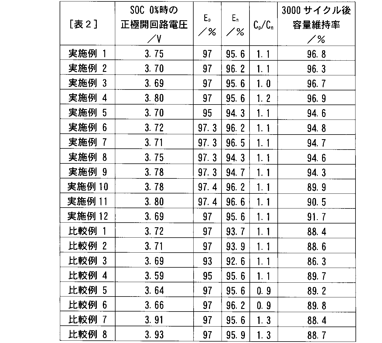
表2に示すとおり、実施例1~12の電池の全てにおいて、正極の充放電容量Epの方が負極の充放電容量Enよりも高く、負極の充放電容量Enが94%以上、且つ単位面積当たりの正極と負極との容量比Cp/Cnが1.0以上1.2以下だった。つまり、実施例1~12では、上述した(1)式、(2)式、及び(3)式の全てを満たしていた。これら実施例1~12では、(1)式、(2)式、及び(3)式のうち少なくとも1つを満たしていない比較例1~8の電池と比較して、3000サイクル後の容量維持率が高かった。
以上に説明した少なくとも一つの実施形態および実施例に係る二次電池は、(1)式、(2)式、及び(3)式の全てを満たしているため、SOCが0%である時の正極電位が下がりくく、充放電サイクル寿命を向上することができる。
本発明のいくつかの実施形態を説明したが、これらの実施形態は、例として提示したものであり、発明の範囲を限定することは意図していない。これら新規な実施形態は、その他の様々な形態で実施されることが可能であり、発明の要旨を逸脱しない範囲で、種々の省略、置き換え、変更を行うことができる。これら実施形態やその変形は、発明の範囲や要旨に含まれると同様に、特許請求の範囲に記載された発明とその均等の範囲に含まれるものである。
Claims (6)
- リチウム含有マンガン酸化物とリチウム含有ニッケルコバルトマンガン酸化物とを含む正極活物質を備える正極活物質含有層を含む正極と、
リチウムチタン酸化物と前記リチウムチタン酸化物とは異なるLi挿入-脱離酸化物とを含む負極活物質を備える負極活物質含有層を含む負極と、
非水電解質とを含み、かつ下記(1)式、下記(2)式、及び下記(3)式を満たす、二次電池。
Ep>En (1)
En≧94% (2)
1.0≦Cp/Cn≦1.2 (3)
但し、Epは3.0V(vs.Li/Li+)以上4.25V(vs.Li/Li+)以下の充放電範囲における前記正極の充放電効率、Enは1.4V(vs.Li/Li+)以上2.0V(vs.Li/Li+)以下の充放電範囲における前記負極の充放電効率、Cpは前記正極の充放電範囲が3.0V(vs.Li/Li+)以上4.25V(vs.Li/Li+)以下である時の単位面積当たりの充電容量(mAh/m2)、Cnは前記負極の充放電範囲が1.4V(vs.Li/Li+)以上2.0V(vs.Li/Li+)以下である時の単位面積当たりの充電容量(mAh/m2)である。 - 前記二次電池を0.2Cで1.8Vまで放電した時の前記正極の開回路電圧が3.6V(vs.Li/Li+)以上3.9V(vs.Li/Li+)以下である、請求項1に記載の二次電池。
- 前記正極活物質における前記リチウム含有ニッケルコバルトマンガン酸化物の含有量が2wt%以上20wt%以下であり、前記負極活物質における前記Li挿入-脱離酸化物の含有量が3wt%以上30wt%以下である、請求項1または2に記載の二次電池。
- 前記正極の厚さが80μm以下である、請求項1~3のいずれか1項に記載の二次電池。
- 前記Li挿入-脱離酸化物は、ニオブチタン複合酸化物および酸化チタンからなる群より選択される1以上を含む、請求項1~4のいずれか1項に記載の二次電池。
- 請求項1~5のいずれか1項に記載の二次電池を含む、電池パック。
Priority Applications (1)
| Application Number | Priority Date | Filing Date | Title |
|---|---|---|---|
| PCT/JP2020/011896 WO2021186601A1 (ja) | 2020-03-18 | 2020-03-18 | 二次電池及び電池パック |
Applications Claiming Priority (1)
| Application Number | Priority Date | Filing Date | Title |
|---|---|---|---|
| PCT/JP2020/011896 WO2021186601A1 (ja) | 2020-03-18 | 2020-03-18 | 二次電池及び電池パック |
Publications (1)
| Publication Number | Publication Date |
|---|---|
| WO2021186601A1 true WO2021186601A1 (ja) | 2021-09-23 |
Family
ID=77771014
Family Applications (1)
| Application Number | Title | Priority Date | Filing Date |
|---|---|---|---|
| PCT/JP2020/011896 Ceased WO2021186601A1 (ja) | 2020-03-18 | 2020-03-18 | 二次電池及び電池パック |
Country Status (1)
| Country | Link |
|---|---|
| WO (1) | WO2021186601A1 (ja) |
Cited By (1)
| Publication number | Priority date | Publication date | Assignee | Title |
|---|---|---|---|---|
| CN118040014A (zh) * | 2024-04-10 | 2024-05-14 | 瑞浦兰钧能源股份有限公司 | 一种二次电池及其制备方法与应用 |
Citations (5)
| Publication number | Priority date | Publication date | Assignee | Title |
|---|---|---|---|---|
| JP2012134125A (ja) * | 2010-12-20 | 2012-07-12 | Ind Technol Res Inst | 正極材料構造およびその製造方法 |
| WO2017046895A1 (ja) * | 2015-09-16 | 2017-03-23 | 株式会社 東芝 | 組電池及び電池パック |
| JP2018045966A (ja) * | 2016-09-16 | 2018-03-22 | 株式会社東芝 | 二次電池、電池パック及び車両 |
| JP2018045931A (ja) * | 2016-09-16 | 2018-03-22 | 株式会社東芝 | 二次電池、電池パック及び車両 |
| JP2019016457A (ja) * | 2017-07-04 | 2019-01-31 | 第一工業製薬株式会社 | 電極塗工液用分散剤、該電極塗工液用分散剤を含む電極塗工液組成物、該電極塗工液組成物を用いて作製された蓄電デバイス用電極、および該電極を備える蓄電デバイス |
-
2020
- 2020-03-18 WO PCT/JP2020/011896 patent/WO2021186601A1/ja not_active Ceased
Patent Citations (5)
| Publication number | Priority date | Publication date | Assignee | Title |
|---|---|---|---|---|
| JP2012134125A (ja) * | 2010-12-20 | 2012-07-12 | Ind Technol Res Inst | 正極材料構造およびその製造方法 |
| WO2017046895A1 (ja) * | 2015-09-16 | 2017-03-23 | 株式会社 東芝 | 組電池及び電池パック |
| JP2018045966A (ja) * | 2016-09-16 | 2018-03-22 | 株式会社東芝 | 二次電池、電池パック及び車両 |
| JP2018045931A (ja) * | 2016-09-16 | 2018-03-22 | 株式会社東芝 | 二次電池、電池パック及び車両 |
| JP2019016457A (ja) * | 2017-07-04 | 2019-01-31 | 第一工業製薬株式会社 | 電極塗工液用分散剤、該電極塗工液用分散剤を含む電極塗工液組成物、該電極塗工液組成物を用いて作製された蓄電デバイス用電極、および該電極を備える蓄電デバイス |
Cited By (1)
| Publication number | Priority date | Publication date | Assignee | Title |
|---|---|---|---|---|
| CN118040014A (zh) * | 2024-04-10 | 2024-05-14 | 瑞浦兰钧能源股份有限公司 | 一种二次电池及其制备方法与应用 |
Similar Documents
| Publication | Publication Date | Title |
|---|---|---|
| EP2980894B1 (en) | Nonaqueous electrolyte battery and battery pack | |
| US11527751B2 (en) | Nonaqueous electrolyte battery and battery pack | |
| CN109196694B (zh) | 非水电解质电池及电池包 | |
| WO2016132436A1 (ja) | 非水電解質電池及び電池パック | |
| CN111727519B (zh) | 电极、电池及电池包 | |
| US11394050B2 (en) | Nonaqueous electrolyte battery and battery pack | |
| CN105322134A (zh) | 非水电解质电池及电池包 | |
| US20200403219A1 (en) | Electrode group, battery, and battery pack | |
| JPWO2020194439A1 (ja) | 電極群、電池、及び電池パック | |
| EP3859855A1 (en) | Secondary battery | |
| JP7106749B2 (ja) | 電極、電池、及び電池パック | |
| JP6699908B2 (ja) | 非水電解質電池及び電池パック | |
| WO2021186601A1 (ja) | 二次電池及び電池パック | |
| JP7024083B2 (ja) | 正極、非水電解質電池、及び電池パック | |
| WO2022059336A1 (ja) | 電極、電池及び電池パック | |
| US20260081150A1 (en) | Nonaqueous electrolyte battery and battery pack | |
| JP7467162B2 (ja) | 非水電解質電池及び電池パック | |
| WO2026062905A1 (ja) | 電極、二次電池及び電池パック | |
| WO2026062859A1 (ja) | 電池及び電池パック | |
| WO2025196904A1 (ja) | 電池及び電池パック |
Legal Events
| Date | Code | Title | Description |
|---|---|---|---|
| 121 | Ep: the epo has been informed by wipo that ep was designated in this application |
Ref document number: 20925388 Country of ref document: EP Kind code of ref document: A1 |
|
| NENP | Non-entry into the national phase |
Ref country code: DE |
|
| 122 | Ep: pct application non-entry in european phase |
Ref document number: 20925388 Country of ref document: EP Kind code of ref document: A1 |
|
| NENP | Non-entry into the national phase |
Ref country code: JP |