WO2021186584A1 - 基地局、基地局システム及び通信方法 - Google Patents
基地局、基地局システム及び通信方法 Download PDFInfo
- Publication number
- WO2021186584A1 WO2021186584A1 PCT/JP2020/011812 JP2020011812W WO2021186584A1 WO 2021186584 A1 WO2021186584 A1 WO 2021186584A1 JP 2020011812 W JP2020011812 W JP 2020011812W WO 2021186584 A1 WO2021186584 A1 WO 2021186584A1
- Authority
- WO
- WIPO (PCT)
- Prior art keywords
- base station
- mac
- processing unit
- mac frame
- base stations
- Prior art date
- Legal status (The legal status is an assumption and is not a legal conclusion. Google has not performed a legal analysis and makes no representation as to the accuracy of the status listed.)
- Ceased
Links
Images





Classifications
-
- H—ELECTRICITY
- H04—ELECTRIC COMMUNICATION TECHNIQUE
- H04W—WIRELESS COMMUNICATION NETWORKS
- H04W40/00—Communication routing or communication path finding
-
- H—ELECTRICITY
- H04—ELECTRIC COMMUNICATION TECHNIQUE
- H04L—TRANSMISSION OF DIGITAL INFORMATION, e.g. TELEGRAPHIC COMMUNICATION
- H04L1/00—Arrangements for detecting or preventing errors in the information received
- H04L1/12—Arrangements for detecting or preventing errors in the information received by using return channel
- H04L1/16—Arrangements for detecting or preventing errors in the information received by using return channel in which the return channel carries supervisory signals, e.g. repetition request signals
- H04L1/1607—Details of the supervisory signal
- H04L1/1657—Implicit acknowledgement of correct or incorrect reception, e.g. with a moving window
-
- H—ELECTRICITY
- H04—ELECTRIC COMMUNICATION TECHNIQUE
- H04L—TRANSMISSION OF DIGITAL INFORMATION, e.g. TELEGRAPHIC COMMUNICATION
- H04L45/00—Routing or path finding of packets in data switching networks
- H04L45/66—Layer 2 routing, e.g. in Ethernet based MAN's
-
- H—ELECTRICITY
- H04—ELECTRIC COMMUNICATION TECHNIQUE
- H04W—WIRELESS COMMUNICATION NETWORKS
- H04W36/00—Hand-off or reselection arrangements
- H04W36/02—Buffering or recovering information during reselection ; Modification of the traffic flow during hand-off
-
- H—ELECTRICITY
- H04—ELECTRIC COMMUNICATION TECHNIQUE
- H04W—WIRELESS COMMUNICATION NETWORKS
- H04W36/00—Hand-off or reselection arrangements
- H04W36/08—Reselecting an access point
-
- H—ELECTRICITY
- H04—ELECTRIC COMMUNICATION TECHNIQUE
- H04W—WIRELESS COMMUNICATION NETWORKS
- H04W74/00—Wireless channel access
- H04W74/08—Non-scheduled access, e.g. ALOHA
- H04W74/0808—Non-scheduled access, e.g. ALOHA using carrier sensing, e.g. carrier sense multiple access [CSMA]
Definitions
- the embodiment relates to a base station, a base station system, and a communication method.
- the wireless LAN terminal connects to a network such as the Internet via a base station.
- a network such as the Internet
- the terminal switches the base station to be connected. Such switching is called handover or the like.
- the terminal disconnects from the connected base station and connects to the next base station again. Overhead occurs when switching base stations.
- the embodiment provides a base station, a base station system, and a communication method capable of suppressing an overhead for switching base stations.
- the base station operates as a first base station in a base station system having a first base station and at least two second base stations.
- the base station has a MAC processing unit and a communication processing unit.
- the MAC processing unit processes the MAC layer to generate a first MAC frame that is commonly used by the first base station and the second base station.
- the communication processing unit transmits the first MAC frame to the second base station.
- a base station it is possible to provide a base station, a base station system, and a communication method capable of suppressing an overhead for switching base stations.
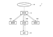
- FIG. 1 is a diagram showing a configuration of an example of a communication system according to an embodiment.
- FIG. 2 is a diagram showing a hardware configuration of an example of the first base station.
- FIG. 3 is a diagram showing a hardware configuration of an example of the second base station.
- FIG. 4 is a diagram showing a hardware configuration of an example of a terminal.
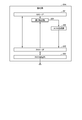
- FIG. 5 is a diagram showing processing of the MAC layer during communication between the first base station and the second base station and the terminal.
- FIG. 6 is a functional block diagram of the first base station.
- FIG. 7 is a functional block diagram of the second base station.
- FIG. 8 is a flowchart showing a transmission process of an example of the first base station.
- FIG. 9 is a flowchart showing a transmission process of an example of the second base station.
- FIG. 10 is a timing chart showing the time change of the state of the PHY processing unit of each of the second base stations in the processing shown in FIG.
- FIG. 11 is a flowchart showing a reception process of an example of the second base station.
- FIG. 12 is a flowchart showing a reception process of an example of the first base station.
- FIG. 1 is a diagram showing a configuration of an example of a communication system according to an embodiment.
- the communication system 1 has a first base station 10, second base stations 20A, 20B, 20C, and a terminal 30.
- the first base station 10 and the second base stations 20A, 20B, 20C operate as one access point (AP) for the terminal 30.
- the second base stations 20A, 20B, and 20C use the MAC address set in the wireless module of the first base station 10 as their own MAC address.
- the first base station 10 is a base station as a higher-level AP that centrally manages the processing of the MAC layers of the second base stations 20A, 20B, and 20C.
- the first base station 10 is configured to be able to connect to the network 40.
- the second base stations 20A, 20B, and 20C are base stations as lower APs that directly transmit and receive radio signals to and from the terminal 30.
- the second base stations 20A, 20B, and 20C are each configured to be able to transmit and receive wireless signals to and from the terminal 30 in a predetermined service area. Further, when communicating with the first base station 10, the second base stations 20A, 20B, and 20C assign MAC addresses individually set to the respective radio modules of the second base stations 20A, 20B, and 20C. You may use it.
- the second base stations 20A, 20B, and 20C may be arranged so that overlapping areas are formed in the service area, or may be arranged so that overlapping areas are not formed. In the following description, it is assumed that the second base stations 20A, 20B, and 20C are arranged so as to form an overlapping area in the service area. Further, in FIG. 1, three second base stations are shown. The second base station may be one or more.
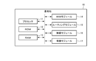
- FIG. 2 is a diagram showing a hardware configuration of an example of the first base station 10.
- the first base station 10 includes a processor 11, a ROM (Read Only Memory) 12, a RAM (Random Access Memory) 13, a WAN (Wide Area Network) module 14, a routing module 15, a wireless module 16, and the like. It has a wired module 17.
- the processor 11 is a processing device that controls the entire first base station 10.
- the processor 11 is, for example, a CPU (Central Processing Unit).
- the processor 11 is not limited to the CPU. Further, an ASIC (Application Specific IC) or the like may be used instead of the CPU. Further, the number of processors 11 may be two or more instead of one.
- ROM 12 is a read-only storage device.
- the ROM 12 stores the firmware and various programs required for the operation of the first base station 10.
- RAM 13 is a storage device that can be arbitrarily written.
- the RAM 13 is used as a work area for the processor 11, and temporarily stores the firmware and the like stored in the ROM 12.
- the WAN module 14 is a module including an interface for the first base station 10 to communicate with, for example, a server (not shown) via the network 40.
- the WAN module 14 is configured to connect to the network 40 via, for example, an optical line.
- the routing module 15 is connected to the WAN module 14 and is configured to perform routing according to the destination information of the IP packet from the WAN module.
- the first base station 10 does not necessarily have to have the routing module 15.
- the first base station 10 may be configured to access a router provided outside the first base station 10 by wireless communication or wired communication and connect to the network 40 via this router.
- the wireless module 16 is a module configured to perform necessary processing for wireless LAN communication.
- the wireless module 16 processes, for example, the LLC (Logical Link Control) layer and the MAC (Media Access Control) layer on the data transferred from the processor 11 to generate a MAC frame.
- the MAC frame contains an error in the MAC header containing the MAC address commonly used in the first base station 10, the second base stations 20A, 20B, and 20C, and the MAC payload including the data transferred from the processor 11 and the like. Includes detection code (FCS).
- FCS Includes detection code
- the commonly used MAC address is, for example, the MAC address of the first base station 10, which is a higher-level AP.
- the wireless module 16 extracts data from the MAC frame transmitted from the terminal 30 via any of the second base stations 20A, 20B, and 20C, and transfers the data to, for example, the processor 11.
- the wired module 17 is a module configured to perform necessary processing for wired communication with the second base stations 20A, 20B, and 20C.
- the wired module 17 is connected to each of the second base stations 20A, 20B, and 20C via a cable.
- a connection method a coaxial cable, ROF (Radio on Fiber), or the like can be considered.
- the signal transmitted from the wired module 17 is received at the target base station of the second base stations 20A, 20B, 20C, and the signal transmitted from the second base stations 20A, 20B, 20C is received by the wired module 17.
- the wired module 17 may be configured to be able to communicate by any wired communication method as long as it is configured to be received.
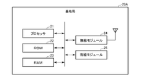
- FIG. 3 is a diagram showing a hardware configuration of an example of the second base station 20A.
- the second base stations 20B and 20C may have the same hardware configuration as the second base station 20A.
- the hardware configuration of the second base stations 20B and 20C is the same as that of the second base station 20A, and the description of the hardware configuration of the second base stations 20B and 20C will be omitted.
- the second base station 20A has a processor 21, a ROM (Read Only Memory) 22, a RAM (Random Access Memory) 23, a wireless module 24, and a wired module 25.
- ROM Read Only Memory
- RAM Random Access Memory
- the processor 21 is a processing device that controls the entire second base station 20A.
- the processor 21 is, for example, a CPU (Central Processing Unit).
- the processor 11 is not limited to the CPU. Further, an ASIC (Application Specific IC) or the like may be used instead of the CPU. Further, the number of processors 21 may be two or more instead of one.
- ROM 22 is a read-only storage device.
- the ROM 22 stores the firmware and various programs required for the operation of the second base station 20A.
- the RAM 23 is a storage device that can be arbitrarily written.
- the RAM 23 is used as a work area for the processor 21, and temporarily stores the firmware and the like stored in the ROM 22.
- the wireless module 24 is a module configured to perform necessary processing for wireless LAN communication.
- the wireless module 24 performs physical layer processing on the MAC frame received from the first base station 10 via the wired module 25 to convert the MAC frame into a wireless signal.
- the wireless module 24 adds a physical header to the MAC frame.
- the physical header includes a PLCP (Physical Layer Convergence Protocol) preamble and a PLCP header.
- the wireless module 24 converts a MAC frame to which a physical header is added into a wireless signal.
- the wireless module 24 transmits a wireless signal to the terminal 30.
- the wireless module 24 extracts a MAC frame from the wireless signal received from the terminal 30.
- the wired module 25 is a module configured to perform necessary processing for wired communication with the first base station 10.
- the wired module 25 is connected to the first base station 10 via a cable.
- a connection method a coaxial cable, ROF (Radio on Fiber), or the like can be considered. If the signal transmitted from the wired module 25 is received by the first base station 10 and the signal transmitted from the first base station 10 is received by the wired module 25, the wired module 25 is configured. , It may be configured so that it can communicate by any wired communication method.
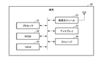
- FIG. 4 is a diagram showing a hardware configuration of an example of the terminal 30.
- the terminal 30 is a terminal device (station) such as a smartphone.
- the terminal 30 may be a mobile terminal, a terminal mounted on a mobile body, or a fixed terminal.
- the terminal 30 has a processor 31, a ROM 32, a RAM 33, a wireless module 34, a display 35, and a storage 36.
- the processor 31 is a processing device that controls the entire terminal 30.
- the processor 31 is, for example, a CPU.
- the processor 31 is not limited to the CPU. Further, ASIC or the like may be used instead of the CPU. Further, the number of processors 31 may be two or more instead of one.
- ROM 32 is a read-only storage device.
- the ROM 32 stores the firmware and various programs required for the operation of the terminal 30.
- the RAM 33 is a storage device that can be arbitrarily written.
- the RAM 33 is used as a work area for the processor 31, and temporarily stores the firmware and the like stored in the ROM 32.
- the wireless module 34 is a module configured to perform necessary processing for wireless LAN communication. For example, the wireless module 34 processes the data transferred from the processor 31 in the MAC layer to form a MAC frame for wireless communication, and processes the configured MAC frame in the physical layer to form the MAC frame. Is converted into a radio signal and transmitted to the first base station 10. As will be described later, the radio signal addressed to the first base station 10 can be received by the second base stations 20A, 20B, 20C. Further, the radio module 34 receives radio signals from the second base stations 20A, 20B, and 20C, extracts data from the received radio signals, and transfers the data to, for example, the processor 21.
- the display 35 is a display device that displays various screens.
- the display 35 may be a liquid crystal display, an organic EL display, or the like. Further, the display 35 may include a touch panel.
- the storage 36 is a storage device such as a hard disk.
- the storage 36 stores, for example, various applications executed by the processor 31.
- FIG. 5 is a diagram showing processing of the MAC layer at the time of communication between the first base station 10, the second base stations 20A, 20B, 20C and the terminal 30.
- the processing of the MAC layer in FIG. 5 complies with the IEEE 802.11 standard.
- FIG. 5 both the processing on the transmitting side and the processing on the receiving side are shown.
- the other wireless module performs processing on the receiving side.
- the wireless modules on the transmitting side and the receiving side are described without distinction.
- step S10 the radio module performs A-MSDU aggregation. Specifically, the wireless module combines a plurality of LLC packets input from the LLC layer to generate an A-MSDU (Aggregate-MAC service data unit).
- A-MSDU Aggregate-MAC service data unit
- step S11 the wireless module assigns a sequence number (SN) to the A-MSDU.
- the sequence number is a unique number for identifying the A-MSDU.
- step S12 the wireless module fragmentes (divides) the A-MSDU into a plurality of MPDUs (MAC protocol data units).
- step S13 the wireless module encrypts each MPDU and generates an encrypted MPDU.
- step S14 the wireless module adds a MAC header and an error detection code (FCS) to each encrypted MPDU.
- the error detection code is, for example, a CRC (Cyclic Redundancy Check) code.
- step S15 the wireless module performs A-MPDU aggregation. Specifically, the wireless module combines a plurality of MPDUs to generate an A-MPDU (Aggregate-MAC protocol data unit) as a MAC frame.
- A-MPDU Aggregate-MAC protocol data unit
- the wireless module processes the physical layer of the MAC frame.
- the radio module 16 of the first base station 10 is the MAC from step S11 to step S15. Perform layer processing.
- the radio module 24 of the second base stations 20A, 20B, 20C performs the physical layer processing.
- the wireless module 34 of the terminal 30 performs the processing of the MAC layer and the processing of the physical layer from step S10 to step S15.
- the radio module processes the physical layer to extract MAC frames from the radio signal. After that, the wireless module performs the processing of the MAC layer shown in FIG.
- step S20 the wireless module performs A-MPDU deaggregation. Specifically, the wireless module divides the A-MPDU into MPDU units.
- the wireless module detects an error. For example, the radio module determines whether or not the reception of the radio signal is successful by CRC. When the reception of the radio signal fails, the radio module may make a retransmission request. At this time, the wireless module may request retransmission in units of MPDU. On the other hand, when the reception of the radio signal is successful, the radio module performs the following processing.
- step S22 the wireless module performs address detection. At this time, the wireless module determines whether or not the sent MPDU is addressed to itself based on the address recorded in the MAC header of each MPDU. When it is not addressed to you, the wireless module does not perform the following processing. When addressed to itself, the wireless module does the following:
- step S23 the wireless module decrypts the encrypted MPDU.
- step S24 the wireless module defragments the MPDU. That is, the wireless module restores the A-MSDU from the plurality of MPDUs.
- step S25 the wireless module performs A-MSDU deaggregation. Specifically, the wireless module restores the A-MSDU to an LLC packet in MSDU units.
- the wireless module After step S25, the wireless module outputs the LLC packet to the upper layer of the MAC layer.
- the upper layer is, for example, an LLC layer.
- the radio module 24 of the second base stations 20A, 20B, 20C processes the physical layer. And the processing of the MAC layer from step S20 to step S22.
- the radio module 16 of the first base station 10 processes the MAC layer from step S23 to step S25.
- the wireless module 34 of the terminal 30 performs the physical layer processing and the MAC layer processing from step S20 to step S25.
- FIG. 6 is a functional block diagram of the first base station 10.
- the first base station 10 includes an LLC processing unit 101, an LLC interface (LLC-IF) 102, a MAC processing unit 103, network interfaces (NW-IF) 104A, 104B, 104C, and a physical (PHY) selection unit. It has 105 and a carrier sense control unit 106. LLC processing unit 101, LLC interface (LLC-IF) 102, MAC processing unit 103, network interface (NW-IF) 104A, 104B, 104C, physical (PHY) selection unit 105, carrier sense control unit 106. Is realized by, for example, a processor 11, a wireless module 16, and a wired module 17.
- the LLC processing unit 101 processes the data transferred from the server on the network 40, for example, in the LLC layer to generate an LLC packet.
- the LLC layer process includes, for example, a process of adding a DSAP (Destination Service Access Point) header, a SSAP (Source Service Access Point) header, or the like to the data. Further, the LLC processing unit 101 extracts data from the LLC packet and outputs the extracted data to the upper layer.
- the upper layer is, for example, an application layer.
- the LLC-IF102 is an interface for mediating signals between the LLC processing unit 101 and the MAC processing unit 103.
- LLC-IF102 has, for example, a queue. This queue temporarily stores the LLC packet generated by the LLC processing unit 101. In addition, this queue temporarily stores the LLC packet extracted from the MAC frame by the MAC processing unit 103.
- the MAC processing unit 103 When transmitting data from the first base station 10, the MAC processing unit 103 generates a MAC frame from an LLC packet input via the LLC-IF102.
- the MAC frame is generated according to the processes of steps S10 to S15 shown in FIG. Further, the MAC processing unit 103 performs processing based on the MAC header of the MAC frame input from the NW-IF104A, 104B, 104C to extract the LLC packet, and outputs the extracted LLC packet to the LLC-IF102. Extraction of the LLC packet from the MAC frame is performed according to the processes of steps S22 to S25 shown in FIG.
- the MAC processing unit 103 may have a queue for each access category (AC).
- the access category may include, for example, VO (Voice), VI (Video), BE (Best effort), and BK (Background).
- the NW-IF104A performs processing necessary for signal communication between the first base station 10 and the second base station 20A.
- the NW-IF104B performs processing necessary for signal communication between the first base station 10 and the second base station 20B.
- the NW-IF104C performs processing necessary for signal communication between the first base station 10 and the second base station 20C.
- the NW-IF104A, 104B, and 104C each have a queue, for example. This queue temporarily stores the signal (MAC frame) generated by the MAC processing unit 103. Further, this queue temporarily stores signals transmitted from each of the second base stations 20A, 20B, and 20C. Further, the NW-IF104A, 104B, and 104C perform processing according to their respective communication methods.
- the NW-IF104A, 104B, 104C perform EO conversion (electrical-optical conversion) to convert an electric signal into an optical signal, and convert this optical signal into a second base station 20A, It is transmitted to the target base station of 20B and 20C. Further, the NW-IF 104A, 104B, 104C perform OE (optical-electric conversion) to convert an optical signal from the second base stations 20A, 20B, 20C into an electric signal, and convert this electric signal into an electric signal, and the electric signal is converted into a MAC processing unit 103. Output to. Further, the NW-IF 104A, 104B, and 104C output the information for executing the carrier sense from the corresponding second base station to the carrier sense control unit 106.
- EO conversion electric-optical conversion
- OE optical-electric conversion
- the PHY selection unit 105 is any one of the second base stations 20A, 20B, 20C according to the information for carrying out the carrier sense from the second base stations 20A, 20B, 20C acquired by the carrier sense control unit 106. Is selected as the base station used for communication with the terminal 30. Details of the selection of the PHY selection unit 105 will be described later.
- the carrier sense control unit 106 performs various controls for EDCA (Enhanced Distribution Channel Access). For example, the carrier sense control unit 106 uses CSMA / CA (Carrier Sense Multiple Access with Collision Avoidance) to determine the state of the channel between the second base stations 20A, 20B, 20C and the terminal. The determination of the channel state is made based on the information for performing the carrier sense acquired via the NW-IF104A, 104B, 104C. Then, the carrier sense control unit 106 outputs the determination result of the channel state to the PHY selection unit 105. Here, the carrier sense control unit 106 may have an access parameter for each AC.
- CSMA / CA Carrier Sense Multiple Access with Collision Avoidance
- FIG. 7 is a functional block diagram of the second base station 20A.
- the second base stations 20B and 20C may have the same functions as the second base station 20A.
- the functions of the second base stations 20B and 20C are the same as those of the second base station 20A, and the description of the functions of the second base stations 20B and 20C will be omitted.
- the second base station 20A has a network interface (NW-IF) 201, a physical interface (PHY-IF) 202, a physical (PHY) processing unit 203, an error detection unit 204, and an ACK generation unit 205. ..
- the NW-IF201 performs processing necessary for communication between the second base station 20A and the first base station 10.
- NW-IF201 has a queue. This queue temporarily stores the signal (MAC frame) transmitted by the first base station 10. In addition, this queue temporarily stores the signal output from the error detection unit 204. Further, the NW-IF201 performs processing according to the communication method. For example, if the communication method is ROF, the NW-IF201 performs EO conversion to convert an electric signal from PHY-IF202 into an optical signal, and transmits this optical signal to the first base station 10. Further, the NW-IF201 performs OE conversion to convert an optical signal from the first base station 10 into an electric signal, and outputs this electric signal to the PHY-IF202. Further, the NW-IF201 sequentially transmits the information for carrying out the carrier sense sent from the PHY processing unit 203 via the PHY-IF202 to the first base station 10.
- the PHY-IF202 is used for signal mediation between the NW-IF201 and the PHY processing unit 203, for signal mediation between the PHY processing unit 203 and the error detection unit 204, and between the PHY processing unit 203 and the ACK generation unit.
- the PHY-IF202 has, for example, a queue. This queue temporarily stores the signal (MAC frame) temporarily stored in the NW-IF201. In addition, the signal extracted by the PHY processing unit 203 is temporarily stored.
- the PHY processing unit 203 mainly processes the physical layer for wireless LAN communication with the terminal 30. For example, the PHY processing unit 203 performs physical layer processing on the MAC frame stored in the PHY-IF202, converts the MAC frame into a wireless signal, and transmits the wireless signal to the terminal 30. Further, the PHY processing unit 203 measures the information necessary for carrying out the carrier sense and notifies the first base station 10. Carrier sense may be performed using, for example, CCA (Clear Channel Assessment). CCA is a method of determining whether or not a channel is free by the received power (RSSI) in the PHY processing unit 203. In this case, the PHY processing unit 203 measures RSSI.
- CCA is a method of determining whether or not a channel is free by the received power (RSSI) in the PHY processing unit 203. In this case, the PHY processing unit 203 measures RSSI.
- the information necessary for carrying out the carrier sense is sent to the carrier sense control unit 106 of the first base station 10. Further, the PHY processing unit 203 extracts a MAC frame from the radio signal received from the terminal 30 and outputs the MAC frame to the PHY-IF202. Further, the PHY processing unit 203 broadcasts the beacon frame.
- the MAC address included in the beacon frame is a MAC address commonly used by the first base station 10 and the second base stations 20A, 20B, and 20C.
- the error detection unit 204 detects an error in the MAC frame in order to determine whether or not the data transmitted from the terminal 30 has been correctly received. Error detection is performed using FCS. Error detection may be performed in MPDU units. When there is no error in the MAC frame, the error detection unit 204 outputs the MAC frame to the NW-IF201 and causes the ACK generation unit 205 to generate an acknowledgment (ACK) indicating that the reception was normally performed. Make a request. On the other hand, when the error detection unit 204 has an error in the MAC frame, the error detection unit 204 discards the MAC frame.
- the ACK generation unit 205 generates an ACK in response to a request from the error detection unit 204, and outputs the generated ACK to the PHY processing unit 203 via the PHY-IF202. In this case, the PHY processing unit 203 transmits an ACK to the terminal 30.
- ACK may be a block ACK.
- the block ACK is, for example, an ACK for receiving acknowledgment in MPDU units.
- the block ACK is generated according to the bitmap created by the error detection unit 204 according to the error detection result for each data of the MPDU unit included in the MAC frame.
- the operation of the communication system 1 will be described. First, the operation when the base stations (first base station 10, second base stations 20A, 20B, 20C) transmit a radio signal and the terminal 30 receives the radio signal will be described.
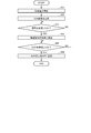
- FIG. 8 is a flowchart showing a transmission process of an example of the first base station 10.
- the MAC processing unit 103 determines whether or not data to be transmitted via the LLC processing unit 101 and the LLC-IF102 has been input from an upper layer such as the application layer.
- the process of FIG. 8 ends.
- the process proceeds to step S32.
- step S32 the MAC processing unit 103 processes the input data (LLC packet) in the MAC layer shown in FIG. 5 to generate a MAC frame.
- step S33 the carrier sense control unit 106 determines an empty channel based on the RSSI input from the second base stations 20A, 20B, 20C via the NW-IF104A, 104B, 104C.
- step S34 the carrier sense control unit 106 determines from the carrier sense result whether or not the channels of a plurality of base stations of the second base stations 20A, 20B, and 20C are free.
- the carrier sense control unit 106 corresponds to a base station when the received power in the PHY processing unit is below the threshold value over the carrier sense period in which the AIFS (Arbitration InterFrame Space) is added with the random backoff period. Channel is determined to be free.
- AIFS is an access parameter indicating a radio signal transmission interval. That is, in the embodiment, the access parameters are standardized in the second base stations 20A, 20B, and 20C.
- step S34 When it is determined in step S34 that only one base station channel is free, the carrier sense control unit 106 notifies the PHY selection unit 105 of, for example, the ID of the base station with a free channel. The PHY selection unit 105 notifies the MAC processing unit 103 of this ID as a selection result. After that, the process proceeds to step S40. In step S34, it may be determined that the channels of all the base stations are not available. In this case, the carrier sense control unit 106 may wait for processing.
- step S35 the carrier sense control unit 106 transmits a sounding frame via the NW-IF corresponding to any of the second base stations 20A, 20B, and 20C with a free channel. It is not necessary to transmit the sounding frame when the second base station to be used is associated with the terminal to be the transmission destination. For example, if the carrier sense control unit 106 or the PHY selection unit 105 holds the power received from the terminal 30 for each second base station, when it is determined that the channels are free in a plurality of base stations, You can select the one with high reception power.
- step S36 the carrier sense control unit 106 determines whether or not the reception result of the sounding response signal has been acquired from each NW-IF corresponding to the base station in which the channel of the NW-IF 104A, 104B, 104C is free. judge. This reception result is the received power of the sounding response signal.
- the carrier sense control unit 106 waits for processing.
- the carrier sense control unit 106 outputs each reception result to the PHY selection unit 105. After this, the process proceeds to step S37.
- step S37 the PHY selection unit 105 selects a base station to be used for transmitting data to the terminal 30 according to the reception result of the sounding response signal. For example, the PHY selection unit 105 selects the base station having the highest received power of the sounding response signal. After the selection, the PHY selection unit 105 notifies the MAC processing unit 103 of, for example, the ID of the selected base station as the selection result.
- step S38 the MAC processing unit 103 transmits a MAC frame using the NW-IF corresponding to the selected base station.
- step S39 the MAC processing unit 103 determines whether or not ACK has been received. When it is determined in step S39 that ACK has been received, the process of FIG. 8 ends. When it is determined in step S39 that ACK has not been received, the MAC processing unit 103 waits for processing. When it is determined that the ACK has not been received for a predetermined time, it may be determined that the time is over. In this case, the MAC processing unit 103 may retransmit the MAC frame. Further, the MAC processing unit 103 may retransmit the MAC frame by receiving the notification of the transmission failure from the second base stations 20A, 20B, and 20C.
- step S40 the MAC processing unit 103 transmits a MAC frame using the NW-IF corresponding to the selected base station. After that, the process proceeds to step S39.
- FIG. 9 is a flowchart showing a transmission process of an example of the second base station 20A.
- the second base stations 20B and 20C may operate in the same manner as the second base station 20A.
- the operation of the second base stations 20B and 20C is assumed to be the same as that of the second base station 20A, and the description of the operation of the second base stations 20B and 20C will be omitted.
- step S51 the PHY processing unit 203 acquires information for carrying out carrier sense. For example, PHY processing unit 203 measures RSSI for CCA.
- step S52 the PHY processing unit 203 transmits the CCA result to the first base station 10 using the NW-IF201.
- step S53 the PHY processing unit 203 determines whether or not a signal such as a MAC frame has been input. When it is determined in step S53 that no signal has been input, the PHY processing unit 203 waits for processing. When it is determined in step S53 that the signal has been input, the process proceeds to step S54.
- the PHY processing unit 203 transmits a wireless signal. For example, when a MAC frame is input, the PHY processing unit 203 performs physical layer processing on the MAC frame to convert the MAC frame into a wireless signal. Then, the PHY processing unit 203 transmits a wireless signal to the terminal 30. When the sounding frame is input, the PHY processing unit 203 processes the physical layer to convert the sounding frame into a sounding signal which is a radio signal. Then, the PHY processing unit 203 transmits the sounding signal to the terminal 30. In this case, the PHY processing unit 203 waits for the reception of the sounding response signal including the sounding response frame from the terminal 30. Then, when the sounding response signal is received, the PHY processing unit 203 transmits the reception result of the sounding response signal to the first base station 10. The reception result is, for example, the received power of the sounding response signal.
- step S55 the PHY processing unit 203 determines whether or not an ACK from the terminal 30 has been received. When it is determined in step S55 that the ACK from the terminal 30 has been received, the process proceeds to step S56. When it is determined in step S55 that ACK has not been received, the MAC processing unit 103 waits for processing. When it is determined that the ACK has not been received for a predetermined time, it may be determined that the time is over. In this case, the MAC processing unit 103 may notify the first base station 10 that the transmission has failed.
- step S56 the PHY processing unit 203 transmits an ACK to the first base station 10 using the NW-IF201. After that, the process of FIG. 9 ends.
- the second base station 20A converts the MAC frame received from the first base station 10 into a wireless signal as it is and transmits it to the terminal 30.
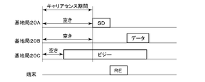
- FIG. 10 is a timing chart showing the time change of the state of the PHY processing units of the second base stations 20A, 20B, and 20C in the processing shown in FIG.
- the second base station 20A and the second base station 20B are in an empty state because the received power of the PHY processing unit 203 within the carrier sense period is below the threshold value.
- the second base station 20C is in a busy state within the carrier sense period.
- the carrier sense control unit 106 of the first base station 10 transmits a sounding frame.
- the base station that has received the sounding frame transmits the sounding signal to the terminal 30.
- the second base station 20A transmits a sounding signal (SD) to the terminal 30.
- SD sounding signal
- the terminal 30 that has received the sounding signal returns a sounding response signal (RE).
- the sounding response signal is received by each of the second base station 20A and the second base station 20B.
- Each of the PHY processing units 203 of the second base station 20A and the second base station 20B measures the received power as a result of receiving the sounding response signal. Then, each PHY processing unit 203 transmits the received power as a result of receiving the sounding response signal to the first base station 10.
- the first base station 10 selects a base station to be used for transmitting data based on the reception results of the sounding signals of the second base station 20A and the second base station 20B, respectively. In the example of FIG. 10, the second base station 20B is selected. Therefore, the second base station 20B transmits a radio signal including data to the terminal 30.
- the second base station when the channels of the plurality of second base stations are open at the time of data transmission from the base station, the second base station having the best communication condition among them transmits the data. Selected as a base station for.
- the terminal 30 transmits data and the base stations (first base station 10, second base stations 20A, 20B, 20C) receive the data
- the terminal 30 specifies a MAC address commonly used by the first base station 10 and the second base stations 20A, 20B, and 20C as the destination MAC address when transmitting the radio signal.
- Data transmission by the terminal 30 is performed using, for example, an EDCA similar to that of a base station. The description of the detailed data transmission operation of the terminal 30 will be omitted.
- FIG. 11 is a flowchart showing a reception process of an example of the second base station 20A.
- the second base stations 20B and 20C may operate in the same manner as the second base station 20A.
- the operation of the second base stations 20B and 20C is assumed to be the same as that of the second base station 20A, and the description of the operation of the second base stations 20B and 20C will be omitted.
- step S71 the PHY processing unit 203 determines whether or not a radio signal has been received. When it is determined in step S71 that the radio signal has not been received, the process of FIG. 11 ends. When it is determined in step S71 that the radio signal has been received, the process proceeds to step S72.
- step S72 the PHY processing unit 203 processes the physical layer and extracts the MAC frame from the radio signal. Then, the error detection unit 204 performs error detection based on the FCS of the MAC frame.
- step S73 the error detection unit 204 determines whether or not there is an error in the data. When it is determined in step S73 that there is no error in the data, the process proceeds to step S74. When it is determined in step S73 that there is an error in the data, the error detection unit 204 discards the data. In this case, the process of FIG. 11 ends. When the data has an error, the error detection unit 204 may determine that the data is addressed to its own station and then notify the first base station 10 of the error. As a result, the first base station 10 can determine the necessity of the retransmission request.
- step S74 the error detection unit 204 determines whether or not the received data is addressed to its own station. That is, the error detection unit 204 determines whether or not the MAC address is an address commonly used by the first base station 10 and the second base stations 20A, 20B, and 20C. When it is determined in step S74 that the received data is addressed to the own station, the process proceeds to step S75. When it is determined in step S74 that the received data is not addressed to the own station, the error detection unit 204 discards the data. In this case, the process of FIG. 11 ends.
- step S75 the error detection unit 204 instructs the ACK generation unit 205 to generate an ACK.
- the ACK generation unit 205 generates an ACK, and the PHY processing unit 203 transmits the ACK to the terminal 30.
- step S76 the error detection unit 204 transmits a MAC frame to the first base station 10 using the NW-IF201. After that, the process of FIG. 11 ends.
- the second base station 20A transmits the MAC frame to the first base station 10 as it is.
- FIG. 12 is a flowchart showing a reception process of an example of the first base station 10.
- the MAC processing unit 103 determines whether or not a MAC frame has been input via at least one of NW-IF104A, 104B, and 104C.
- the process of FIG. 12 ends.
- the process proceeds to step S82.
- step S82 the MAC processing unit 103 determines whether or not a plurality of MAC frames have been input.
- the radio signal may be received by these a plurality of base stations simultaneously or with a certain time difference.
- the same MAC frame is sent to the MAC processing unit 103 from a plurality of base stations.
- Step S82 is a determination of this state.
- the process proceeds to step S83.
- step S84 When it is determined in step S82 that a plurality of MAC frames have not been input, the process proceeds to step S84.
- a retransmission request may be made as necessary.
- the MAC processing unit 103 selects one of the MAC frames. For example, the MAC processing unit 103 selects a MAC frame from a base station received with the highest received power. Further, since the same MAC frame is transmitted from each base station, the MAC processing unit 103 may select the MAC frame in a predetermined priority order such as the order of the second base stations 20A, 20B, and 20C. good. In order to prevent a plurality of second base stations from transmitting ACK at the same time, a primary second base station is defined for each terminal, and the second base station has a successful reception and a destination. You may send an ACK when you are your own station and the source is your primary terminal. As for which second base station is the primary, the power received from the terminal may be the highest.
- step S84 the MAC processing unit 103 performs the processing of the MAC layer shown in FIG. 5 to extract the LLC packet. Then, the MAC processing unit 103 outputs the extracted LLC packet to the LLC processing unit 101.
- step S85 the LLC processing unit 101 extracts data from the LLC packet.
- step S86 the LLC processing unit 101 outputs the extracted data to the upper layer.
- the upper layer is, for example, an application layer. After that, the process of FIG. 12 ends.
- the processing of the MAC layer of one or more second base stations is collectively performed by one first base station.
- the first base station and one or more second base stations can be regarded as one base station. Therefore, for example, when the terminal 30 moves from the service area of the second base station 20A to the service area of the second base station 20B, it is not necessary to switch the connection at the time of handover. This reduces the overhead associated with switching connections during handover.
- the service area can be substantially expanded by increasing the number of the second base stations installed.
- each second base station detects an error in the received MAC frame. As a result, it is possible to support a protocol with stricter time constraints than the error detection performed by the first base station.
- one second base station for transmitting a radio signal is selected according to the sounding result.
- communication with the terminal can be performed using the base station having the best channel condition.
- communication between the first base station and the second base station is performed by wired communication.
- communication between the first base station and the second base station is likely to be stable.
- the first base station is not provided with a PHY processing unit. That is, in the embodiment, the first base station does not directly communicate wirelessly with the terminal. On the other hand, the first base station may also have a PHY processing unit.
- one PHY processing unit is provided in one second base station.
- a plurality of different PHY processing units such as a 2.4 GHz band PHY processing unit and a 5 GHz band PHY processing unit, may be provided in one second base station.
- carrier sense may be performed for each PHY processing unit.
- the PHY selection unit 105 may select one PHY processing unit based on the CCA result obtained for each PHY processing unit.
- the error detection is performed at the second base station.
- error detection may be performed at the first base station.
- the error detection unit of the first base station detects an error in the data received by each of the three second base stations. Then, the error detection unit transmits a block ACK corresponding to the error of these data from one second base station.
- each process according to the above-described embodiment can be stored as a program that can be executed by a processor that is a computer.
- it can be stored and distributed in a storage medium of an external storage device such as a magnetic disk, an optical disk, or a semiconductor memory.
- the processor reads the program stored in the storage medium of the external storage device, and the operation is controlled by the read program, so that the above-described processing can be executed.
- the present invention is not limited to the above embodiment, and can be variously modified at the implementation stage without departing from the gist thereof.
- each embodiment may be carried out in combination as appropriate, and in that case, the combined effect can be obtained.
- the above-described embodiment includes various inventions, and various inventions can be extracted by a combination selected from a plurality of disclosed constituent requirements. For example, even if some constituent requirements are deleted from all the constituent requirements shown in the embodiment, if the problem can be solved and the effect is obtained, the configuration in which the constituent requirements are deleted can be extracted as an invention.
Landscapes
- Engineering & Computer Science (AREA)
- Computer Networks & Wireless Communication (AREA)
- Signal Processing (AREA)
- Mobile Radio Communication Systems (AREA)
Abstract
Description
以下、実施形態の変形例を説明する。実施形態では、第1の基地局には、PHY処理部が設けられていないとしている。つまり、実施形態では、第1の基地局は、端末とは直接的には無線通信をしない。これに対し、第1の基地局もPHY処理部を有していてもよい。
10…第1の基地局
11…プロセッサ
12…ROM
13…RAM
14…WANモジュール
15…ルーティングモジュール
16…無線モジュール
17…有線モジュール
20A,20B,20C…第2の基地局
21…プロセッサ
22…ROM
23…RAM
24…無線モジュール
25…有線モジュール
30…端末
31…プロセッサ
32…ROM
33…RAM
34…無線モジュール
35…ディスプレイ
36…ストレージ
40…ネットワーク
101…LLC処理部
102…LLC-IF
103…MAC処理部
104A,104B,104C…NW-IF
105…PHY選択部
106…キャリアセンス制御部
201…NW-IF
202…PHY-IF
203…PHY処理部
204…誤り検出部
205…ACK生成部
Claims (10)
- 第1の基地局と、少なくとも2つの第2の基地局とを有する基地局システムにおける前記第1の基地局として動作する基地局であって、
MAC層の処理を行って前記第1の基地局と前記第2の基地局とで共通して用いられる第1のMACフレームを生成するMAC処理部と、
前記第1のMACフレームを前記第2の基地局に送信する通信処理部と、
を具備する基地局。 - 前記通信処理部は、さらに、端末から前記第2の基地局に送信されたMACフレームであって前記第1の基地局と前記第2の基地局とで共通して用いられるMACアドレスを含む第2のMACフレームを前記第2の基地局から受信し、
前記MAC処理部は、前記第2のMACフレームに対してMAC層の処理を行って前記第2のMACフレームからデータを抽出する、
請求項1に記載の基地局。 - それぞれの前記第2の基地局からのキャリアセンスを実施するための情報に基づき、前記第2の基地局で共通のアクセスパラメータを用いてそれぞれの前記第2の基地局のチャネルの空き状況を判定するキャリアセンス制御部をさらに具備する、請求項1又は2に記載の基地局。
- それぞれの前記第2の基地局のキャリアセンスを実施するための情報に基づき、前記第1のMACフレームの送信先の1つの前記第2の基地局を選択する物理選択部をさらに具備する、請求項1乃至3の何れか1項に記載の基地局。
- 前記物理選択部は、
前記キャリアセンスを実施するための情報から、1つの前記第2の基地局にだけ空きチャネルがあるときには、空きチャネルを有する1つの前記第2の基地局を選択し、
前記キャリアセンスを実施するための情報から、2以上の前記第2の基地局に空きチャネルがあるときには、空きチャネルを有する2以上の前記第2の基地局の少なくともいずれかにサウンディングフレームを送信して2以上の前記第2の基地局の少なくともいずれかから前記サウンディングフレームを端末に送信させ、前記端末からのサウンディング応答フレームの受信結果を2以上の前記第2の基地局から受信し、受信したサウンディング応答フレームの受信結果に基づいて1つの前記第2の基地局を選択する、
請求項4に記載の基地局。 - 前記通信処理部は、前記第1のMACフレームを有線で前記第2の基地局に送信する、請求項1乃至5の何れか1項に記載の基地局。
- 第1の基地局と、少なくとも2つの第2の基地局とを有する基地局システムにおける前記第2の基地局として動作する基地局であって、
第1のMACフレームを前記第1の基地局から受信する通信処理部と、
物理層の処理を行って前記第1のMACフレームを含む無線信号を生成し、生成した無線信号を端末に送信する物理処理部と、
を具備する基地局。 - 前記物理処理部は、さらに、前記第1の基地局と前記第2の基地局とで共通して用いられるMACアドレスを含む第2のMACフレームを含む無線信号を受信し、受信した無線信号に対して物理層の処理を行って前記無線信号から前記第2のMACフレームを抽出し、
前記基地局は、
前記第2のMACフレームの受信における誤りの有無を検出する誤り検出部と、
前記誤りの有無の結果に応じたアクノリッジを生成し、生成したアクノリッジを前記通信処理部を介して前記端末に送信するアクノリッジ生成部と、
をさらに具備する請求項7に記載の基地局。 - 第1の基地局と、少なくとも2つの第2の基地局とを有する基地局システムであって、
前記第1の基地局は、
MAC層の処理を行って前記第1の基地局と前記第2の基地局とで共通して用いられる第1のMACフレームを生成するMAC処理部と、
前記第1のMACフレームを前記第2の基地局に送信する第1の通信処理部と、
を具備し、
前記第2の基地局は、
前記第1のMACフレームを前記第1の基地局から受信する第2の通信処理部と、
物理層の処理を行って前記第1のMACフレームを含む無線信号を生成し、生成した無線信号を端末に送信する物理処理部と、
を具備する、
基地局システム。 - 第1の基地局と、少なくとも2つの第2の基地局とを有する基地局システムにおける通信方法であって、
前記第1の基地局においてMAC層の処理を行って前記第1の基地局と前記第2の基地局とで共通して用いられる第1のMACフレームを生成することと、
前記第1のMACフレームを前記第1の基地局から前記第2の基地局に送信することと、
前記第2の基地局において、前記第1のMACフレームを前記第1の基地局から受信すること、
前記第2の基地局において物理層の処理を行って前記第1のMACフレームを含む無線信号を生成することと、
前記無線信号を端末に送信することと、
を具備する通信方法。
Priority Applications (3)
| Application Number | Priority Date | Filing Date | Title |
|---|---|---|---|
| PCT/JP2020/011812 WO2021186584A1 (ja) | 2020-03-17 | 2020-03-17 | 基地局、基地局システム及び通信方法 |
| JP2022508682A JP7533569B2 (ja) | 2020-03-17 | 2020-03-17 | 基地局、基地局システム及び通信方法 |
| US17/911,681 US12588058B2 (en) | 2020-03-17 | 2020-03-17 | Base station, base station system, and communication method |
Applications Claiming Priority (1)
| Application Number | Priority Date | Filing Date | Title |
|---|---|---|---|
| PCT/JP2020/011812 WO2021186584A1 (ja) | 2020-03-17 | 2020-03-17 | 基地局、基地局システム及び通信方法 |
Publications (1)
| Publication Number | Publication Date |
|---|---|
| WO2021186584A1 true WO2021186584A1 (ja) | 2021-09-23 |
Family
ID=77771928
Family Applications (1)
| Application Number | Title | Priority Date | Filing Date |
|---|---|---|---|
| PCT/JP2020/011812 Ceased WO2021186584A1 (ja) | 2020-03-17 | 2020-03-17 | 基地局、基地局システム及び通信方法 |
Country Status (3)
| Country | Link |
|---|---|
| US (1) | US12588058B2 (ja) |
| JP (1) | JP7533569B2 (ja) |
| WO (1) | WO2021186584A1 (ja) |
Citations (4)
| Publication number | Priority date | Publication date | Assignee | Title |
|---|---|---|---|---|
| JP2007214974A (ja) * | 2006-02-10 | 2007-08-23 | Nippon Telegr & Teleph Corp <Ntt> | 無線中継システムおよび無線中継方法 |
| JP2019012867A (ja) * | 2015-11-20 | 2019-01-24 | シャープ株式会社 | 無線通信システムおよび基地局装置 |
| JP2019110403A (ja) * | 2017-12-15 | 2019-07-04 | 日本電信電話株式会社 | 無線基地局システムおよび通信方法 |
| JP2020036206A (ja) * | 2018-08-30 | 2020-03-05 | 株式会社東芝 | 電子装置 |
Family Cites Families (28)
| Publication number | Priority date | Publication date | Assignee | Title |
|---|---|---|---|---|
| US6757270B1 (en) * | 1999-06-11 | 2004-06-29 | Lucent Technologies Inc. | Low back haul reactivation delay for high-speed packet data services in CDMA systems |
| ATE348461T1 (de) * | 2000-07-11 | 2007-01-15 | Cisco Tech Inc | Verfahren und system zur reservierung von bandbreite in einem funkkommunikationssystem |
| EP1698194A1 (en) * | 2003-12-23 | 2006-09-06 | Electronics And Telecommunications Research Institute | Apparatus and method for testing and analyzing base station with smart antenna, and protocol structure |
| US7620370B2 (en) * | 2006-07-13 | 2009-11-17 | Designart Networks Ltd | Mobile broadband wireless access point network with wireless backhaul |
| US20080068979A1 (en) * | 2006-09-14 | 2008-03-20 | Motorola, Inc. | Adaptive and preemptive scheduling of transmissions |
| EP2169969A4 (en) * | 2007-06-12 | 2013-05-29 | Fujitsu Ltd | COMMUNICATION METHOD AND RADIO NETWORK CONTROL IN A MOBILE COMMUNICATION SYSTEM |
| US8532057B2 (en) * | 2008-06-25 | 2013-09-10 | Lg Electronics Inc. | Handover support method using dedicated ranging code |
| DK2702716T3 (en) * | 2011-11-04 | 2015-03-09 | Ericsson Telefon Ab L M | MANAGING redundant data IN A COMMUNICATION SYSTEM |
| US10374776B2 (en) * | 2014-11-20 | 2019-08-06 | Industrial Technology Research Institute | Base station, user equipment for integrating multiple rats using carrier aggregation and methods thereof |
| US10708810B2 (en) * | 2014-12-23 | 2020-07-07 | Interdigital Patent Holdings, Inc. | Methods for WiFi integration in cellular systems |
| JP6689209B2 (ja) * | 2015-01-26 | 2020-04-28 | シャープ株式会社 | 端末装置および基地局装置 |
| JP6488206B2 (ja) * | 2015-07-08 | 2019-03-20 | 株式会社東芝 | 無線通信装置および無線通信方法 |
| US10349320B2 (en) * | 2016-03-29 | 2019-07-09 | Sharp Kabushiki Kaisha | User equipments, base stations and methods |
| JP6640670B2 (ja) * | 2016-07-15 | 2020-02-05 | 株式会社東芝 | 無線通信装置および無線通信方法 |
| JP6485886B2 (ja) | 2017-07-07 | 2019-03-20 | Necプラットフォームズ株式会社 | 無線通信システム及び制御方法 |
| US10952252B2 (en) * | 2017-08-08 | 2021-03-16 | Cable Television Laboratories, Inc. | Systems and methods for coordinated multi point operation in the unlicensed band |
| CN109729566B (zh) * | 2017-10-27 | 2021-01-29 | 华为技术有限公司 | 一种信息传输方法和设备 |
| CN109788427A (zh) * | 2017-11-10 | 2019-05-21 | 索尼公司 | 无线通信系统中的装置和方法、计算机可读存储介质 |
| US11582000B2 (en) * | 2018-05-11 | 2023-02-14 | Qualcomm Incorporated | Front loaded sounding reference signal and physical random access channel signal |
| EP3651498A1 (en) * | 2018-11-12 | 2020-05-13 | Panasonic Intellectual Property Corporation of America | User equipment involved in cell re-selection |
| US11678314B2 (en) * | 2019-06-24 | 2023-06-13 | Qualcomm Incorporated | Packet duplication carrier enhancements |
| US11452107B2 (en) * | 2019-07-22 | 2022-09-20 | Qualcomm Incorporated | Low overhead component carrier selection for multi-component carrier communication |
| US11581978B2 (en) * | 2019-08-06 | 2023-02-14 | Qualcomm Incorporated | Uplink repetition configuration |
| US12267715B2 (en) * | 2019-09-03 | 2025-04-01 | Qualcomm Incorporated | Sounding reference signal channel measurement for sidelink communication |
| WO2021168599A1 (en) * | 2020-02-24 | 2021-09-02 | Qualcomm Incorporated | Reference signal configurations for uplink beam selection |
| EP4111626B1 (en) * | 2020-02-25 | 2025-08-20 | Qualcomm Incorporated | Beam switching techniques for uplink transmission |
| EP4152793A4 (en) * | 2020-05-14 | 2023-10-11 | Sony Group Corporation | Communication device, communication method, and program |
| WO2023056165A1 (en) * | 2021-10-01 | 2023-04-06 | Qualcomm Incorporated | Channel for eavesdropping-mitigation and secret key generation |
-
2020
- 2020-03-17 WO PCT/JP2020/011812 patent/WO2021186584A1/ja not_active Ceased
- 2020-03-17 US US17/911,681 patent/US12588058B2/en active Active
- 2020-03-17 JP JP2022508682A patent/JP7533569B2/ja active Active
Patent Citations (4)
| Publication number | Priority date | Publication date | Assignee | Title |
|---|---|---|---|---|
| JP2007214974A (ja) * | 2006-02-10 | 2007-08-23 | Nippon Telegr & Teleph Corp <Ntt> | 無線中継システムおよび無線中継方法 |
| JP2019012867A (ja) * | 2015-11-20 | 2019-01-24 | シャープ株式会社 | 無線通信システムおよび基地局装置 |
| JP2019110403A (ja) * | 2017-12-15 | 2019-07-04 | 日本電信電話株式会社 | 無線基地局システムおよび通信方法 |
| JP2020036206A (ja) * | 2018-08-30 | 2020-03-05 | 株式会社東芝 | 電子装置 |
Also Published As
| Publication number | Publication date |
|---|---|
| US20230147391A1 (en) | 2023-05-11 |
| JP7533569B2 (ja) | 2024-08-14 |
| JPWO2021186584A1 (ja) | 2021-09-23 |
| US12588058B2 (en) | 2026-03-24 |
Similar Documents
| Publication | Publication Date | Title |
|---|---|---|
| US12144044B2 (en) | Multi-link communications of a wireless network | |
| US20220369403A1 (en) | Multi-link communications of a wireless network with dynamic link configuration | |
| JP7053033B2 (ja) | 無線通信装置および方法 | |
| CN102726100A (zh) | 在移动环境中切换中继连接 | |
| US20260019194A1 (en) | Wireless communication device and method, and wireless communication terminal and method | |
| WO2023140540A1 (en) | Quick recovery indication and retransmission request | |
| EP4231552B1 (en) | Transmission station and reception station | |
| JP7533569B2 (ja) | 基地局、基地局システム及び通信方法 | |
| JP7405154B2 (ja) | 基地局、通信方法及び通信プログラム | |
| JP5628858B2 (ja) | 転送制御装置、転送制御方法、及び転送制御プログラム | |
| JP7420259B2 (ja) | 基地局、基地局システム、及び通信方法 | |
| JP7259999B2 (ja) | 基地局、端末、及び無線通信方法 | |
| US12301446B2 (en) | Communication device, communication system, communication method, and non-transitory computer readable medium storing communication program | |
| JP2006217110A (ja) | 無線lanシステムとそのマルチレート制御方法 | |
| US12568400B2 (en) | Communication apparatus and communication method for cooperative transmission between a plurality of access points | |
| JP7452660B2 (ja) | 基地局及び通信方法 | |
| JP7401794B2 (ja) | 基地局装置、中継装置、及び通信システム | |
| US20250274888A1 (en) | Communication apparatus, control method, and computer-readable storage medium | |
| US20240056884A1 (en) | Transmitting station and receiving station | |
| WO2025018090A1 (ja) | アクセスポイント、端末、及び、通信方法 | |
| CN121419029A (zh) | 一种通信方法和装置 | |
| JP2022084770A (ja) | 無線通信装置および方法 | |
| WO2026092296A1 (zh) | 一种通信方法和装置 | |
| WO2023058544A1 (ja) | 通信装置、制御方法、及び、プログラム | |
| KR20100114439A (ko) | Ieee 802.11 무선랜 환경에서의 직접 링크 설정 방법 |
Legal Events
| Date | Code | Title | Description |
|---|---|---|---|
| 121 | Ep: the epo has been informed by wipo that ep was designated in this application |
Ref document number: 20925811 Country of ref document: EP Kind code of ref document: A1 |
|
| ENP | Entry into the national phase |
Ref document number: 2022508682 Country of ref document: JP Kind code of ref document: A |
|
| NENP | Non-entry into the national phase |
Ref country code: DE |
|
| 122 | Ep: pct application non-entry in european phase |
Ref document number: 20925811 Country of ref document: EP Kind code of ref document: A1 |
|
| WWG | Wipo information: grant in national office |
Ref document number: 17911681 Country of ref document: US |