WO2021186568A1 - アンテナ装置 - Google Patents
アンテナ装置 Download PDFInfo
- Publication number
- WO2021186568A1 WO2021186568A1 PCT/JP2020/011768 JP2020011768W WO2021186568A1 WO 2021186568 A1 WO2021186568 A1 WO 2021186568A1 JP 2020011768 W JP2020011768 W JP 2020011768W WO 2021186568 A1 WO2021186568 A1 WO 2021186568A1
- Authority
- WO
- WIPO (PCT)
- Prior art keywords
- antenna
- heat pipe
- heat
- antenna device
- adapter
- Prior art date
- Legal status (The legal status is an assumption and is not a legal conclusion. Google has not performed a legal analysis and makes no representation as to the accuracy of the status listed.)
- Ceased
Links
Images







Classifications
-
- H—ELECTRICITY
- H01—ELECTRIC ELEMENTS
- H01Q—ANTENNAS, i.e. RADIO AERIALS
- H01Q1/00—Details of, or arrangements associated with, antennas
- H01Q1/02—Arrangements for de-icing; Arrangements for drying-out ; Arrangements for cooling; Arrangements for preventing corrosion
-
- B—PERFORMING OPERATIONS; TRANSPORTING
- B60—VEHICLES IN GENERAL
- B60R—VEHICLES, VEHICLE FITTINGS, OR VEHICLE PARTS, NOT OTHERWISE PROVIDED FOR
- B60R11/00—Arrangements for holding or mounting articles, not otherwise provided for
- B60R11/02—Arrangements for holding or mounting articles, not otherwise provided for for radio sets, television sets, telephones, or the like; Arrangement of controls thereof
-
- H—ELECTRICITY
- H01—ELECTRIC ELEMENTS
- H01Q—ANTENNAS, i.e. RADIO AERIALS
- H01Q1/00—Details of, or arrangements associated with, antennas
- H01Q1/27—Adaptation for use in or on movable bodies
- H01Q1/32—Adaptation for use in or on road or rail vehicles
-
- H—ELECTRICITY
- H01—ELECTRIC ELEMENTS
- H01Q—ANTENNAS, i.e. RADIO AERIALS
- H01Q1/00—Details of, or arrangements associated with, antennas
- H01Q1/42—Housings not intimately mechanically associated with radiating elements, e.g. radome
Definitions
- the present disclosure relates to an array-type antenna device mounted on a mobile body.
- the mechanically driven antenna device In order to reduce air resistance, it is necessary to reduce the cross-sectional area (hereinafter referred to as the projected area) of the moving body seen from the front in the traveling direction, or to have a streamlined shape to reduce the separation of the wake. Since it is necessary, the installation space of the antenna device is limited in the moving body.
- the opening surface of the antenna body and the reflecting plate are mechanically driven to control the directivity, so that the mechanical driving device is approximately several tens of centimeters high to be housed in the antenna device. Was needed. Therefore, when the mechanically driven antenna device is mounted on the moving body, there is a limit to the reduction of air resistance.
- the phased array type antenna device includes an antenna array in which a plurality of antenna elements are regularly arranged, and the antenna array electronically controls the directivity by individually phase-controlling the signals transmitted and received by each antenna element. It is possible to reduce the thickness of the entire antenna device.
- the phased array type antenna device in order to increase the communication speed and the communication capacity, it is necessary to increase the frequency of the signal and the antenna element to be highly integrated, and the heat generation density is higher than that of the conventional mechanically driven antenna device. Will be higher. Further, since the antenna element is composed of a semiconductor, it is necessary to sufficiently cool the element and keep the junction temperature at about 100 ° C. or lower in order to obtain desired performance.
- a method of dissipating heat by the running wind obtained by the movement of the moving body has been developed.
- a wiring board, a plurality of antenna elements, a plurality of antenna element operation modules, and a plurality of antenna elements arranged in a predetermined arrangement on one surface of the wiring board are accommodated. It includes an exterior plate on which a plurality of antenna element accommodating holes are formed. The exterior plate is attached to the surface of the moving body with one surface exposed to the external space, transfers the heat generated by the antenna element operation module to the wiring board and the exterior plate, and moves one surface of the exterior plate as the moving body moves. Heat is dissipated from the exterior plate by the flowing air flow.
- Patent Document 2 describes a device that dissipates heat to the inside of a moving body by using a refrigerant pipe and a pump.
- the antenna device When the moving body is moving at high speed, the antenna device is cooled by the obtained running wind.
- the antenna device since the antenna device is covered with a radome and does not come into direct contact with the outside air, it is necessary to transport heat to the external space of the antenna device via an antenna adapter made of a good heat conductive material.
- the antenna adapter cannot be made thick with a thin antenna device, there is a problem that the heat in the central part of the array cannot be sufficiently diffused by the antenna adapter and sufficient heat cannot be dissipated.
- Patent Document 2 is excellent in that it can stably dissipate heat even when the moving body is stopped.
- the pump since the pump is used as a mechanical component, its maintenance is required.
- the purpose of this disclosure is to improve the cooling performance of the thin antenna device without maintenance.
- the antenna device is arranged so as to cover an antenna array having an antenna element that transmits or receives radio waves for communication, an antenna adapter that holds the antenna array and has a gap with the surface of a moving body, and an antenna adapter.
- a skirt that shields outside air from flowing into the gap between the antenna adapter and the surface of the moving object, and a skirt that dissipates heat from the antenna adapter, and a condensing unit that condenses the working fluid vaporized by the evaporating part and the evaporating part. It is equipped with a heat pipe, which is arranged so as to extend from the antenna array toward the skirt.
- FIG. 1 It is a perspective view which shows the appearance of the antenna device which concerns on Embodiment 1.
- FIG. 2 is a perspective view which shows the inside of the antenna device which concerns on Embodiment 1.
- FIG. It is a perspective view which shows the antenna array which concerns on Embodiment 1.
- FIG. It is a figure which showed the coupling structure of the antenna adapter and the mounting bracket which concerns on Embodiment 1.
- FIG. It is a figure which looked at a part of the antenna device from the PP'line of FIG.
- FIG. It is a perspective view which shows the arrangement of the heat pipe which concerns on Embodiment 1.
- FIG. It is a figure which looked at the antenna device from the line AA'in FIG.
- It is a figure which looked at the antenna device from the BB'line of FIG.
- FIG. 5 is a view of the antenna device viewed from the line AA'of FIG. 6 when the heat pipe according to the first embodiment is installed at an angle. It is sectional drawing of the heat pipe which concerns on Embodiment 1.
- FIG. It is a figure which shows the modification of the antenna device which concerns on Embodiment 1.
- FIG. It is a perspective view which shows the arrangement of the heat pipe which concerns on Embodiment 2.
- FIG. It is sectional drawing of the heat pipe which concerns on Embodiment 2.
- FIG. It is a perspective view which shows the arrangement of the heat pipe which concerns on Embodiment 3.
- FIG. 3 shows the arrangement of the heat pipe which concerns on Embodiment 3.
- FIG. 1 is a perspective view showing the appearance of the antenna device 100 according to the first embodiment.
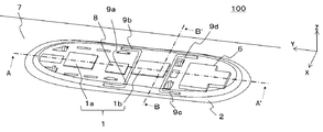
- FIG. 2 is a perspective view showing the inside of the antenna device 100 according to the first embodiment. The basic configuration of the antenna device 100 according to the first embodiment will be described with reference to FIGS. 1 and 2.
- the surface of the antenna device 100 is surrounded by the radome 3 and the skirt 4, and the radome 3, the skirt 4 and the moving body surface 7 are in close contact with each other. Therefore, even when the moving body moves at high speed, the traveling wind does not enter the inside of the antenna device 100.
- the antenna device 100 includes an antenna array 1, an antenna adapter 2, a radome 3, a skirt 4, a power supply 6, and a control circuit 8.
- the antenna device 100 is attached to the surface 7 of a mobile body such as an aircraft and is used for communication using an artificial satellite.
- the direction orthogonal to the moving body surface 7 is defined as the Z axis
- the traveling direction of the moving body is defined as the Y axis
- the width direction of the antenna device 100 orthogonal to them is defined as the X axis.
- the positive direction of the Z axis is referred to as "up”
- the negative direction is referred to as "down”
- the positive direction of the Y axis is referred to as "front”
- the negative direction of the Y axis is referred to as "back”.
- the traveling direction of the moving body shall coincide with the direction in which the front part to the rear part of the moving body are connected by a straight line, and if the moving body is, for example, an aircraft, it coincides with the direction from the nose to the tail wing. do.
- the moving body according to the first embodiment will be described as an aircraft, the moving body is merely an example, and the moving body is not limited to the aircraft.
- FIG. 3 is a schematic view of the antenna array 1 according to the first embodiment.
- the antenna array 1 is a flat plate type communication module, and includes a transmission antenna array 1a for transmitting radio waves to a communication target and a reception antenna array 1b for receiving radio waves from the communication target.
- the transmitting antenna array 1a and the receiving antenna array 1b are arranged on the antenna adapter 2 at intervals from each other. That is, the antenna array 1 is held by the antenna adapter 2.
- the receiving antenna array 1b is arranged on the ⁇ Y axis side of the transmitting antenna array 1a, but the present invention is not limited to this.
- the receiving antenna array 1b may be arranged on the + Y-axis side of the transmitting antenna array 1a. Further, since the transmitting antenna array 1a and the receiving antenna array 1b generate heat due to the transmission or reception of radio waves, they are installed apart from each other.
- the antenna array 1 includes a plurality of antenna elements 13 arranged in a grid pattern and a communication IC 12 that causes the antenna elements 13 to perform a predetermined operation.
- the antenna array 1 is an active electronic scanning antenna array, and adjusts the directivity of radio waves by controlling the phase shift amount of each antenna element 13 in order to track an artificial satellite to be communicated.
- the antenna elements 13 are arranged on a wiring board (not shown) and transmit or receive radio waves for communication to a communication target.
- An RF signal Radio Frequency
- the antenna element 13 generates heat when transmitting and receiving radio waves to and from the communication target. Since a plurality of antenna elements 13 are arranged in the antenna array 1, the heat generation density of the antenna array 1 may increase due to the high integration of the antenna elements 13.
- the number of antenna elements 13 arranged in the antenna array 1 is determined by the scanning angle of radio waves, the estimated amount of loss of radio waves, and the like. Further, the distance between the antenna elements 13 differs depending on the wavelength of the radio wave used for communication. The shorter the wavelength of the radio wave used for communication, the narrower the element spacing of the antenna element 13. For example, when the wavelength of the radio wave used for communication is the Ka band antenna element 13, the size of the antenna array 1 is about several tens of centimeters square.
- the communication IC 12 has a surface facing the surface in contact with the wiring board (not shown) in which the antenna elements 13 are arranged as a heat radiating surface, and the heat radiating surface is arranged so as to be joined to the antenna adapter 2.
- the communication IC 12 includes electronic components such as a phase device that changes the phase of the RF signal transmitted and received by the antenna element 13 and an amplifier that amplifies the RF signal. These electronic components are mounted on a wiring board, are supplied with a required power supply voltage from the power supply 6, and are further supplied with a required control signal from the control circuit 8 to execute a predetermined operation. Each electronic component of the communication IC 12 generates heat during operation.
- the calorific value of the communication IC 12 also differs depending on the semiconductor process of the electronic component. For example, when the heat generation amount of the communication IC 12 is in the kilowatt class, if the heat diffusion ability of the antenna adapter 2 in contact with the heat dissipation surface of the communication IC 12 is low, the central portion of the flat communication IC 12 cannot sufficiently dissipate heat. .. Since each electronic component included in the communication IC 12 is a semiconductor element, it is necessary to keep the junction temperature at about 100 ° C. or lower in order for the communication IC 12 to exhibit the desired performance. The junction temperature is the maximum temperature at which the semiconductor element operates. Therefore, in order for the communication IC 12 to operate, the heat dissipation performance of the antenna adapter 2 which is the heat dissipation surface of the communication IC 12 is important.
- the antenna adapter 2 is, for example, a flat base material, and is horizontally arranged on the upper surface of the moving body. Further, the antenna adapter 2 has a gap with the moving body surface 7 and faces the moving body surface 7. Therefore, the antenna adapter 2 has a surface on the side where the antenna array 1 is arranged (+ Z-axis side surface) and a surface on the side facing the moving body surface 7 (-Z-axis side surface), and faces the moving body surface 7.
- a power supply 6 for supplying electric power to the antenna array 1 and a control circuit 8 for transmitting a control signal to the antenna array 1 are arranged on the surface (the side surface of the ⁇ Z axis).
- the power supply 6 converts the power supply voltage supplied from the moving body into the voltages required by the antenna array 1 and the control circuit 8 and supplies them.
- the power supply 6 is composed of a plurality of elements, each of which is fixed to the antenna adapter 2. In the power source 6, heat is generated according to the electric power to be converted.
- the control circuit 8 is a circuit that controls the antenna array 1.
- a plurality of electronic components are mounted on the control circuit 8, and heat is generated by the operation.
- the antenna adapter 2 is provided with a plurality of through holes 11 penetrating the surface on the side where the antenna array 1 is arranged (+ Z-axis side surface) and the surface on the side facing the moving body surface 7 (-Z-axis side surface). ing.
- the plurality of through holes 11 have different sizes depending on their roles, and most of them are provided to reduce the weight of the antenna adapter 2. Therefore, the antenna adapter 2 can be said to be a frame in which a plurality of holes are provided in the flat plate. Further, some through holes 11 provided on the outer peripheral portion of the antenna adapter 2 are provided with receiving metal fittings (not shown) into which the mounting metal fittings 5a to 5f are fitted.
- the antenna adapter 2 is fixed and supported by, for example, a plurality of mounting brackets 5a to 5d provided on the surface 7 of the moving body. ..
- the force applied to each fixed portion of the antenna adapter 2 is dispersed by the lift.
- the antenna adapter 2 and the moving body surface 7 are fixed and supported by the plurality of mounting brackets 5a to 5d, there is a gap between the antenna adapter 2 and the moving body surface 7.
- the antenna adapter 2 also plays a role of ensuring rigidity so that the entire antenna device 100 is not deformed by lift.
- the antenna adapter 2 is formed by carving out a material having high thermal conductivity. For example, it is a metal material such as aluminum. Therefore, the antenna adapter 2 serves as a heat dissipation path for heat generated in the antenna array 1, the power supply 6, the control circuit 8, and the like.
- the radome 3 is arranged so as to cover the antenna adapter 2 so as to have a gap with the surface (+ Z-axis side surface) on the side where the antenna array 1 of the antenna adapter 2 is arranged, and the antenna array 1 is disturbed by wind, rain, dust, etc. Plays a role in protecting from.
- the radome 3 is continuously connected to the skirt 4 and is fixed to the outer peripheral portion of the antenna adapter 2 by using a plurality of screws.
- the shape of the radome 3 is streamlined.
- the radome 3 since the radome 3 needs to transmit the radio waves transmitted and received by the antenna array 1 to the communication target, the radome 3 is made of a material capable of transmitting the radio waves used for communication. Therefore, as the material of the radome 3, for example, a resin material having a low dielectric constant and easily transmitting radio waves is used. With this configuration, even when the moving body moves at high speed, the air resistance generated in the antenna device 100 attached to the moving body surface 7 can be minimized.
- the skirt 4 is a flat plate provided along the outer circumference of the antenna adapter 2. As shown in FIG. 2, for example, when the antenna adapter 2 has an elliptical shape, the skirt 4 has a hollow elliptical frustum shape.
- the skirt 4 plays a role of preventing outside air from flowing into the gap between the antenna adapter 2 and the moving body surface 7.
- An elastic body 14 such as a rubber packing is attached to the connection between the skirt 4 and the surface 7 of the moving body so as to be in close contact with the surface 7 of the moving body. Since the skirt 4 is provided in close contact with the moving body surface 7, the moving body expands due to pressurization or the like, and even when the moving body surface 7 bends, outside air is introduced into the gap between the antenna adapter 2 and the moving body surface 7. It prevents the inflow.
- the skirt 4 is a member that connects the radome 3 and the moving body surface 7, outside air does not flow into the gap between the antenna adapter 2 and the moving body surface 7, and dew condensation that occurs inside the antenna device 100 is significantly increased. It becomes possible to reduce to.
- the outside air is the air outside the space enclosed by the radome 3, the skirt 4, and the surface 7 of the moving body, which are the outer skins of the antenna device 100. That is, it refers to the air outside the antenna device 100.
- the radome 3 and the skirt 4 have an outer shape symmetrical with respect to the center line AA'direction connecting the front part and the rear part of the moving body, for example.
- the transmitting antenna array 1a and the receiving antenna array 1b are respectively arranged on the surface of the antenna adapter 2 so as to be located on the center line AA'.
- the antenna adapter 2 is a heat radiating surface of a heating element such as an antenna element 13 and is a material having high thermal conductivity, the heat diffusion ability can be improved by increasing the thickness and the cross-sectional area. That is, it is possible to improve the heat dissipation performance by enlarging the heat dissipation surface.
- an increase in the cross-sectional area of the antenna adapter 2 results in an increase in the projected area of the antenna device 100.
- the projected area is the cross-sectional area of the moving body when viewed from the front in the traveling direction.
- Increasing the projected area of the antenna device 100 leads to an increase in the air resistance of the moving body.
- increasing the thickness of the antenna adapter 2 also leads to an increase in the weight of the antenna device 100. Therefore, the thickness and cross-sectional area of the antenna adapter 2 need to be kept to the minimum required size.
- the coupling structure between the antenna adapter 2 and the mobile surface 7 is defined by, for example, ARINC791, which is one of the aircraft standards for commercial aircraft.
- FIG. 4 is a plan view showing the coupling structure of the mounting bracket 5 and the antenna adapter 2 when the inside of the radome 3 is viewed from above.
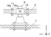
- FIG. 5 is an enlarged cross-sectional view of a part of the antenna device 100 along the PP'line of FIG.
- the mounting bracket 5 provided on the surface 7 of the moving body is coupled to the antenna adapter 2 via the bolt 15a and the receiving bracket 16. Therefore, the antenna adapter 2 can be easily removed from the moving body, and can be easily inspected or replaced at the time of failure.
- a receiving metal fitting 16 is attached to a part of the through hole 11 of the antenna adapter 2 by using a bolt 15b.
- the receiving metal fitting 16 and the mounting metal fitting 5 are connected by using a bolt 15a.
- a cushioning material 17 such as a rubber bush is interposed between the mounting bracket 5 and the receiving bracket 16, and even when the position of the mounting bracket 5 changes due to the pressurization inside the moving body. It plays a role in absorbing the stress caused by the change.
- Aircraft standards (ARINC791, ARINC792, etc.) stipulate that the antenna adapter 2 and the moving body surface 7 should be separated by 8 mm or more.
- the antenna device 100 When a moving object flies, the antenna device 100 also needs a structure to prepare for a lightning strike. Some of the surfaces of the radome 3 are provided with a structure for passing a current during a lightning strike, but if the distance between the inner wall of the radome 3 and the antenna element 13 is too narrow, dielectric breakdown due to electric discharge may occur. .. Therefore, it is preferable that the antenna adapter 2 and the moving body surface 7 have a gap of about 10 mm or more.
- the thickness of the antenna adapter 2 is preferably about 2 cm or less.
- the size of the antenna adapter 2 that is the base material of the antenna array 1 and the like varies depending on the size of the equipment to be mounted, but the size of the antenna for the Ka band defined by ARINC791 exceeds 2 square meters.
- the antenna array 1, the power supply 6, and the control circuit 8 installed in the antenna adapter 2 serve as heating elements.
- the antenna array 1 is the main heat source, and the communication IC 12 of the antenna array 1 needs to maintain the junction temperature at about 100 ° C. or lower. Therefore, in order for the antenna device 100 to operate, it is necessary to improve the heat dissipation performance of the antenna adapter 2 in which the communication IC 12 is installed.
- the running wind (outside air) obtained by the movement can be utilized for cooling the antenna device 100.
- the heating element is not set on the surface of the antenna device 100 in contact with the traveling wind, it is difficult to directly cool the antenna device 100 by the traveling wind. Therefore, in the antenna device 100 attached to the moving body, by providing a radiator in the peripheral portion of the antenna device 100, it is possible to dissipate heat from the radiator via the antenna adapter 2. As a result, the antenna device 100 can be cooled even if the heating element is not installed on the surface of the antenna device 100 in contact with the outside air.
- the radiator of the antenna device 100 is a smooth flat plate.
- the skirt 4 arranged around the antenna adapter 2 is used as a radiator. That is, the heat from the antenna adapter 2 is dissipated by the skirt 4.
- the skirt 4 is a flat metal plate, and there is a limit to the heat flux (the amount of heat that crosses the unit area per unit time) that can be obtained with the outside air. Therefore, in order to obtain high heat dissipation performance in the skirt 4, it is necessary to diffuse the heat transferred to the skirt 4 to the entire skirt 4 in advance.
- the heating element installed in the antenna device 100 diffuses heat to the skirt 4 via the antenna adapter 2. Therefore, by improving the ability of the antenna adapter 2 to diffuse heat, that is, the heat dissipation capacity of the antenna adapter 2, it is possible to diffuse the heat to the entire skirt 4 arranged along the outer periphery of the antenna adapter 2.
- the size of the antenna adapter 2 may be increased, but if the size of the antenna adapter 2 is restricted by aircraft standards or the like, the thickness of the antenna adapter 2 or It is difficult to increase the cross-sectional area, and there is a possibility that heat cannot be sufficiently diffused to the skirt 4.
- a communication IC 12 having a size of several tens of centimeters generates heat of a kilowatt class, sufficient heat diffusion may not be possible. If the heat cannot be sufficiently diffused to the skirt 4, the temperature of the central portion of the communication IC 12 cannot be lowered to 100 ° C. or lower, and the communication IC 12 may not operate as desired.
- the calorific value of the communication IC 12 is less than kilowatts, it is necessary to reduce the thermal resistance up to the skirt 4 which is the heat dissipation surface of the antenna adapter 2 having a thickness of about 2 cm as much as possible.
- the antenna adapter 2 As described above, most of the heat generated by the heating element of the antenna device 100 is transferred through the antenna adapter 2 and dissipated to the outside air using the skirt 4 as a heat radiating surface, but when the thickness of the antenna adapter 2 is thin. May not ensure sufficient heat dissipation.
- the antenna array 1 arranged in the central portion of the antenna adapter 2 has few effective heat dissipation paths because other heating elements are arranged around it, and heat is trapped.
- the antenna adapter 2 is provided with a heat pipe 9 having a high heat transport capacity.
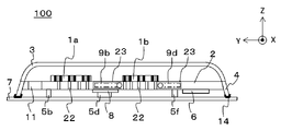
- FIG. 6 is a perspective view showing the antenna adapter 2 transmitted through the antenna device 100 shown in FIG. 7 is a cross-sectional view showing an AA'cross section of the antenna device 100 of FIG. 6, and FIG. 8 is a cross-sectional view showing a BB' cross section of the antenna device 100 of FIG.
- the control circuit 8, the power supply 6, and the antenna array 1 are connected by electrical wiring.
- the control circuit 8, the power supply 6, and the antenna array 1 are arranged on the opposite surfaces (+ Z-axis side surface and ⁇ Z-axis side surface) of the antenna adapter 2, the antenna array 1 of the antenna adapter 2 is arranged.
- a plurality of wiring through holes 22 connecting the + Z-axis side surface and the ⁇ Z-axis side surface for passing the electrical wiring are provided in the portion where the antennas are joined. Therefore, the heat pipes 9 (9a to 9d) are arranged in the antenna adapter 2 so as to surround the antenna array 1 so as not to interfere with the wiring through holes 22 (FIG. 6).
- the heat pipe 9 may be arranged only on one of the antenna arrays 1 having a high heat generation density.
- FIG. 6 shows an example in which the heat pipe 9 is arranged so as to sandwich the receiving antenna array 1b, but the arrangement example is not limited to this.
- the heat pipes 9 (9a to 9d) have a bent portion, and the shape thereof is L-shaped or the like.
- the heat pipes 9 (9a to 9d) need only be provided with a bent portion, and are not limited to the L-shape.
- the volatile working fluid is sealed in a pipe made of a material having high thermal conductivity such as copper and copper alloy, and the heat pipe 9 (9a to 9d) is operated by the heat of the heating element. It includes an evaporating unit 20 that vaporizes the fluid and a condensing unit 21 that condenses the vaporized working fluid.
- the working fluid becomes steam in the evaporation unit 20, moves to the condensation unit 21 and condenses, so that heat can be efficiently transferred.
- the condensed liquid is returned to the evaporation unit 20 again.
- the heat pipes 9 (9a to 9d) are arranged so as to extend from the antenna array 1 toward the skirt 4 so that the evaporation portion 20 of the heat pipe 9 faces the antenna array 1 side and the condensing portion 21 faces the skirt 4 side. ..
- the evaporation unit 20 faces the X-axis direction along the receiving antenna array 1b, and the condensing unit 21 that releases heat is located on the outer periphery of the antenna adapter 2. It is arranged so as to face the Y-axis direction along the adjacent skirt 4.
- the condensing portion 21 is arranged in a direction perpendicular to the traveling direction of the moving body, and the condensing portion 21 is arranged along the traveling direction of the moving body.
- the heat pipe 9a and the heat pipe 9b are arranged so that the condensing end of the heat pipe faces the + Y axis direction
- the heat pipe 9c and the heat pipe 9d are arranged so that the condensing end of the heat pipe faces the ⁇ Y axis direction.
- the condensing portion 21 is arranged in a direction parallel to the traveling direction of the moving body, or the condensing portion 21 is inclined from the traveling direction of the moving body. Including being placed in.
- the antenna device 100 should be low in the height direction in order to reduce air resistance, and it is desired that the antenna device 100 is lightweight.
- the antenna adapter 2 is required to have sufficient strength to withstand the lift received during flight. However, if the thickness of the antenna adapter 2 is about 2 cm, the heat pipe 9 (9a to 9d) is attached to the surface of the antenna adapter 2. It is also possible to place it in. However, considering that the communication radio wave between the antenna array 1 and the artificial satellite to be communicated is not blocked, and that the electrical wiring and insulation between the devices are not obstructed, the antenna adapter 2 should be arranged inside. Is desirable (FIGS. 7 and 8).
- FIG. 7 and 8 show an example in which the heat pipes 9 (9a to 9d) are arranged inside the antenna adapter 2 and within the thickness of the antenna adapter 2.
- the heat pipes 9 (9a to 9d) it is conceivable to provide the antenna adapter 2 with a groove 23 and install the heat pipe 9 (9a to 9d) along the groove 23.
- 9a-9d may be tilted and arranged.
- the end portion of the heat pipe 9a and the heat pipe 9b where the condensing portion 21 is located is tilted in the + Z direction until it fits within the thickness of the antenna adapter 2, and the evaporation portion of the heat pipe 9a and the heat pipe 9b. Tilt the portion where 20 is located in the ⁇ Z direction until it fits within the thickness of the antenna adapter 2.
- the end portion of the heat pipe 9c and the heat pipe 9d where the condensing portion 21 is located is tilted in the + Z direction until it fits within the thickness of the antenna adapter 2, and the portion where the evaporation portion 20 of the heat pipe 9a and the heat pipe 9b is located is tilted. Tilt in the ⁇ Z direction until it fits within the thickness of the antenna adapter 2 (Fig. 9). That is, the condensing portion 21 of the heat pipe 9 (9a to 9d) may be arranged so as to be above the evaporation portion 20.
- FIG. 6 shows an example in which the heat pipes 9 (9a to 9d) are arranged along the receiving antenna array 1b so that the thermal resistance between the heat pipes 9 (9a to 9d) and the receiving antenna array 1b is minimized. If the wiring through holes 22 are concentrated in the central portion of the receiving antenna array 1b, it is desirable to arrange the evaporation portion of the heat pipes 9 (9a to 9d) directly under the receiving antenna array 1b. ..
- the heat pipes 9 (9a to 9d) are arranged inside the antenna adapter 2 and directly below the antenna array 1.
- the heat pipes 9 (9a to 9d) are arranged in this way, the heat transport efficiency from the heating element can be improved, and the heat dissipation performance of the antenna adapter 2 can be improved.
- the improvement of the heat dissipation performance of the antenna adapter 2 it becomes possible to efficiently release heat to the outside by the skirt 4 which is the radiator of the antenna device 100.
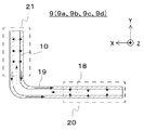
- FIG. 10 is a schematic cross-sectional view of the heat pipes 9 (9a to 9d).
- the structure of the heat pipe 9 and the cooling mechanism will be described with reference to FIG.
- the heat pipes 9a to 9d are distinguished in explaining the arrangement of the heat pipes 9, and are heat pipes 9 having the same structure as the heat pipes 9.
- the heat pipe 9 is a so-called wick type heat pipe 9, and a wick 10 is provided on the wall surface of the pipe.
- the wick 10 has a capillary structure, and the working fluid liquefied in the condensing unit 21 can be returned to the evaporation unit 20 by utilizing the capillary phenomenon of liquid.
- a working fluid is sealed inside the heat pipe 9.
- the larger the latent heat of vaporization the higher the heat transport capacity, so water is generally often used. However, water freezes below freezing. Therefore, when water is used as the working fluid, when the temperature of the heat pipe 9 becomes below the freezing point, the water may condense and expand, which may damage the heat pipe 9.
- the antenna device 100 When the antenna device 100 is mounted on an aircraft, it is exposed to the outside air of about 50 ° C. below freezing point in the sky. Therefore, if the antenna array 1 does not generate heat, the heat pipe 9 is cooled to below freezing point. There is also. Therefore, when water is used as the working fluid, a heating device such as a heater may be attached around the heat pipe 9. When the temperature of the environment in which the heat pipe 9 is used falls below the freezing point, a liquid containing ammonia, ethanol, or the like that does not freeze even below the freezing point may be used as the working fluid. That is, in the environment in which the antenna device 100 is used, a liquid that does not freeze may be used as the working fluid.
- the antenna device 100 attached to an aircraft it is predicted that it will be used in a low temperature environment during flight, so it is desirable to use a liquid that does not freeze under the usage environment as the working fluid of the heat pipe 9.
- the working fluid sealed inside the heat pipe 9 receives heat at the evaporation unit 20 and vaporizes. Since the pressure near the evaporation section 20 rises due to the vaporized working fluid 18, the vaporized working fluid 18 is carried to the condensing section 21 whose pressure is relatively low (broken arrow in FIG. 10).
- the condensing unit 21 is arranged closer to the outside air than the evaporation unit 20, and is cooled by the outside air. Therefore, the vaporized working fluid 18 (broken line arrow in FIG. 10) that has moved from the evaporation unit 20 is cooled and liquefied in the condensation unit 21.
- the working fluid 19 (solid arrow in FIG.
- liquefied in the condensing portion 21 is taken into the wick 10 arranged on the inner wall of the heat pipe 9.
- the liquefied working fluid 19 (solid arrow in FIG. 10) taken into the wick 10 is diffused by the capillary force of the wick 10 and is refluxed to the evaporating section 20 having a relatively lower capillary force than the condensing section 21.
- the liquefied working fluid 19 of the heat pipe 9 is vaporized in the evaporation section 20, carried to the condensation section 21, liquefied in the condensation section 21, and refluxed to the evaporation section 20 is called a reflux cycle. do.
- the heat pipe 9 can transport heat by utilizing the temperature around the heat pipe 9. Therefore, by using the heat pipe 9, heat can be transported without the need for a pump that requires maintenance.
- the heat pipe 9 is arranged so as to extend from the antenna array 1 toward the skirt 4. That is, the evaporation portion 20 of the heat pipe 9 is arranged near the antenna array 1 which is a heating element, and the condensing portion 21 of the heat pipe 9 is arranged near the skirt 4 which exchanges heat with the outside air.
- the working fluid of the heat pipe 9 receives heat from the antenna array 1, and the working fluid of the heat pipe 9 is vaporized.
- the vaporized working fluid 18 is carried to the condensing section 21 which is lower in temperature than the evaporating section 20, and is liquefied in the condensing section 21.
- the liquefied working fluid 19 returns to the evaporation section 20 by the capillary force of the wick 10 provided on the wall surface of the heat pipe 9.
- the heat pipe 9 carries the heat of the heating element from the central portion of the antenna adapter 2 to the outer peripheral portion where the skirt 4 is provided, which leads to improvement of the heat dissipation performance of the antenna adapter 2. That is, the heat diffusion efficiency of the antenna adapter 2 can be improved by providing the heat pipe 9.
- the heat pipe 9 is arranged along the groove 23 provided in the antenna adapter 2, the size of the antenna adapter 2 is not increased and the heating element is used. The heat can be dissipated toward the entire skirt 4.
- the heat of the antenna adapter 2 can be carried to the skirt 4 without increasing the size of the antenna adapter 2 and without maintenance. That is, by improving the heat dissipation performance of the antenna adapter 2, heat can be diffused to the entire skirt 4, and the cooling of the antenna device 100 is improved.
- the recirculation performance (wick limit) of the liquefied working fluid 19 due to the capillary force becomes a bottleneck.
- the maximum heat transport amount Q of the heat pipe 9 is represented by the equation (1).
- M is a term that depends on the characteristics of the working fluid, which is called the merit number.
- Right side second term is a term which depends on the wick properties, K is wick infiltration pressure coefficient, the r c a wick radius.
- the third term on the right side is a term that depends on the dimensions, A w is the cross-sectional area of the wick, and l eff is the effective length of the heat pipe 9.
- the fourth item is a term that depends on body force, where g is the gravitational acceleration, ⁇ is the surface tension, ⁇ l is the density, and ⁇ is the inclination of the heat pipe 9.
- the heat transport capacity is very high and the amount of latent heat is large when the recirculation cycle of the working fluid is operating.
- the thermal conductivity is one to two orders of magnitude higher.
- thermal conductivity performance higher than that of aluminum or copper, which is known as a good thermal conductor can be obtained.
- the equivalent thermal conductivity of the heat pipe 9 installed in the antenna device 100 is about 5000 W / mK
- the use of about four heat pipes 9 between the receiving antenna array 1b and the skirt 4 Thermal resistance can be reduced by about 30%. Therefore, when the air is generated in the kilowatt class, the temperature of the central portion of the receiving antenna array 1b can be kept below the target value even when the flight altitude of the aircraft is low and the outside air temperature is high.
- By increasing the number of heat pipes 9 arranged in the antenna adapter 2 to more than four it is possible to keep the temperature of the device lower.
- the installation space for the heat pipes 9 is limited, and the cost increases as the number of heat pipes 9 increases. Therefore, the maximum heat dissipation performance is achieved with the limited number of heat pipes 9. Is important.
- the recirculation cycle of the working fluid is delayed, and the liquefied working fluid 19 does not return to the evaporating part 20, that is, in a so-called dry-out state, the heat conduction is only the conduction of the pipe material of the heat pipe 9. ,
- the heat transport capacity may drop sharply.
- a factor that hinders the recirculation of the liquefied working fluid 19 is an event in which the body force (apparent weight) applied to the liquefied working fluid 19 cancels the capillary force.
- the antenna device 100 provided with the heat pipe 9 as shown in FIG. 6 is mounted on an aircraft. Since the satellite communication antenna of the aircraft is mainly used for in-flight entertainment, it is rarely used at the time of takeoff and landing, and it operates when cruising in the sky. Strictly speaking, the aircraft is flying with the nose raised about 3 degrees even when cruising in the sky, but for the sake of simplicity, it is assumed that the aircraft's fuselage is parallel to the XY plane (angle of attack 0 degrees). do. At this time, the direction of gravity when the aircraft is cruising (horizontal inertial flight) is considered to be the ⁇ Z axis direction.
- the liquefied working fluid 19 is not affected by body force as long as the heat pipes 9 (9a to 9d) are arranged in the XY plane, so that the liquefied working fluid is not affected. 19 is refluxed by capillary force. Therefore, all the heat pipes 9 (9a to 9d) can exhibit the expected heat transport capacity.
- the heat pipes 9 (9a to 9d) have a bent portion.
- the evaporation unit 20 is arranged so as to face the X-axis direction along the receiving antenna array 1b
- the condensing unit 21 is arranged so as to face the Y-axis direction along the skirt 4.
- the heat pipe 9a and the heat pipe 9b are arranged so that the evaporation portion 20 faces the X-axis direction and the condensing portion 21 faces the + Y-axis direction.
- the heat pipe 9c and the heat pipe 9d are arranged so that the evaporation portion 20 faces the X-axis direction and the condensing portion 21 faces the ⁇ Y-axis direction. That is, the condensing portion 21 of the heat pipe 9 (9a to 9d) is arranged in the direction (Y-axis direction) parallel to the traveling direction (+ Y-axis direction) of the moving body, and the evaporating portion 20 is arranged in the traveling direction (+ Y-axis direction) of the moving body. It is arranged in a direction (X-axis direction) perpendicular to (axial direction).
- At least one heat pipe 9 (9a, 9b) of the heat pipes 9 (9a to 9d) is provided so as to be bent in the same direction (+ Y-axis direction) as the traveling direction (+ Y-axis direction) of the moving body.
- At least one of the heat pipes 9 (9a to 9d) has a condensing portion 21, and the heat pipes 9 (9c, 9d) are in the direction opposite to the traveling direction (+ Y-axis direction) of the moving body (-Y-axis direction). ) Is bent and provided with a condensing portion 21.
- the heat pipes 9a and 9b correspond to the first heat pipe
- the heat pipes 9c and 9d correspond to the second heat pipe.
- the portion of the heat pipe 9 (9a to 9d) facing the Y-axis direction may be affected by the body force depending on the direction in which the acceleration is generated and the return direction of the working fluid.
- a portion arranged in a direction (Y-axis direction) parallel to the traveling direction (+ Y-axis direction) of the moving body may be affected by body force during acceleration. There is sex.
- the heat pipe 9c and the heat pipe 9d are temporarily prevented from recirculating by the body force, but in the heat pipe 9a and the heat pipe 9b, the recirculation is promoted by the body force, so that the heat pipe 9 (9a to 9d) as a whole is affected.
- the heat dissipation performance does not deteriorate.
- the antenna device 100 in which the heat pipes 9 (9a to 9d) are arranged as shown in FIG. 6, at least two heat pipes 9 continue to operate even when the moving body accelerates, so that the antenna device 100 is for reception.
- the antenna array 1b does not cause a sudden temperature rise that causes the junction temperature to exceed the specified value in a short time. That is, the heat pipe 9 does not dry out even during acceleration, and the heat of the antenna adapter 2 can continue to be dissipated to the skirt 4.
- the portion arranged in the direction (+ X-axis direction) perpendicular to the traveling direction (+ Y-axis direction) of the moving body is affected by the body force even during deceleration.
- the portion of the heat pipe 9 (9a to 9d) facing the Y-axis direction may be affected by the body force depending on the direction in which the acceleration is generated and the return direction of the working fluid.
- the heat pipe 99 (9a to 9d) having a bent portion a portion arranged in a direction (Y-axis direction) parallel to the traveling direction (+ Y-axis direction) of the moving body is affected by body force even during deceleration. there is a possibility.
- the heat pipe 9a and the heat pipe 9b are temporarily prevented from recirculating by the body force, but in the heat pipe 9c and the heat pipe 9d, the recirculation is promoted by the body force, so that the heat dissipation performance is not deteriorated.
- the heat pipes 9 (9a to 9d) are arranged as shown in FIG. 6, at least two heat pipes 9 continue to operate even when the moving body decelerates.
- the antenna array 1b does not cause a sudden temperature rise that causes the junction temperature to exceed the specified value in a short time. That is, the heat pipe 9 does not dry out even during deceleration, and the heat of the antenna adapter 2 can continue to be dissipated to the skirt 4.
- the antenna device 100 is thin by arranging the heat pipes 9 (9a to 9d) having the bent portion in the antenna adapter 2 extending from the antenna array 1 toward the skirt 4. Since the antenna device 100 does not require maintenance and the heat dissipation performance of the antenna adapter 2 can be improved, the antenna array 1 can be sufficiently cooled.
- the evaporating portion 20 of the heat pipes 9 (9a to 9d) faces the X-axis direction along the receiving antenna array 1b, and the condensing portion 21 faces the Y-axis direction along the skirt 4.
- the antenna adapter 2 Since it is not necessary to increase the size of the antenna adapter 2, it can also be applied to the thin antenna device 100. In addition, the antenna device 100 can be made thinner, the weight can be reduced, and the fuel efficiency of the moving body can be improved.
- the heat of the antenna adapter 2 can be efficiently transferred to the skirt 4 which is a radiator, heat can be dissipated even if the antenna array 1 or the like which is a heating element is installed in the center of the antenna adapter 2. Even if the communication capacity increases and the heat generation density increases at the center of the antenna adapter 2, the antenna array 1 can be cooled to the operating temperature, so that the antenna array 1 can be kept below the specified temperature. It will be possible.
- the antenna device can be configured according to the first embodiment.
- the cooling performance of 100 can be improved.
- the moving body when the moving body is an aircraft, situations such as cruising (horizontal inertial flight), acceleration and deceleration can be considered, but at least one end of the condensing portion 21 of the heat pipe 9 is oriented in the + Y axis direction, and at least one. Since the ends of the condensing portions 21 of the two heat pipes 9 are oriented in the ⁇ Y axis direction, the cooling performance of the antenna device 100 can be maintained. Further, even if the moving body accelerates or decelerates for a short time required for operation, all the heat pipes 9 mounted on the antenna device 100 do not dry out, and the antenna array 1 is kept below the specified temperature. It will be possible to keep. As a result, the cooling performance can be ensured even while the moving body is accelerating and decelerating, so that the communication service can be stably provided.
- FIG. 11 is a cross-sectional view of the antenna device 100 of the modified example of the antenna device 100 according to the first embodiment as viewed from the Z-axis direction.
- the modification of the present disclosure is a modification of the shape of the antenna adapter 2 and the shape of the heat pipes 9 (9a to 9d) according to the first embodiment.
- the shape of the antenna adapter 2 is an elliptical shape or an oval shape, and the bending of the heat pipes 9 (9a to 9d) is described by taking 90 degrees as an example.
- the antenna device 100 is mounted on a moving body having a fixed traveling direction such as an aircraft, in order to further reduce air resistance, for example, in the case of a drop-shaped shape in which the rear of the antenna adapter 2 is narrowed down. There is also.
- the condensing portion 21 side of the heat pipe 9 (9a to 9d) is arranged so as to be in contact with the skirt 4, the condensing portion 21 side of the heat pipe 9 (9a to 9d) does not follow the Y-axis direction.
- the bending of the heat pipe 9 is at an angle different from 90 degrees.
- at least one heat pipe 9 has the end of the condensing portion 21 facing the + Y axis direction, and at least one heat pipe 9 is a heat pipe.
- the antenna device 100 If the end of the condensing portion 21 of 9 is oriented in the ⁇ Y axis direction, the antenna device 100 according to the first embodiment even if the shape of the antenna adapter 2 of the first embodiment and the bending angle of the heat pipe 9 are different. The same effect as is obtained.
- the end of the condensing portion 21 of the heat pipe 9 is oriented in the + Y axis direction, and in the heat pipe 9c and the heat pipe 9d, the end of the condensing portion 21 of the heat pipe 9 is directed.
- the heat pipe 9a and the heat pipe 9b are condensed portions 21 of the heat pipe 9 when the length of the receiving antenna array 1b in the Y-axis direction is sufficiently long. The same effect can be obtained even if the end of the heat pipe 9c and the heat pipe 9d are arranged so that the end of the condensing portion 21 of the heat pipe 9 faces the + Y-axis direction.
- the number of heat pipes 9 has been described as four, the number of heat pipes 9 is increased if there is a margin in terms of cost, and if there is a margin in the installation space, it is mounted on the antenna adapter 2.
- the heat pipe 9 may be arranged around the transmission antenna array 1a, the control circuit 8, and the like.
- Embodiment 2 The antenna device 100 according to the second embodiment will be described with reference to FIGS. 12 and 13.
- the same reference numerals as those in FIGS. 6 and 10 indicate the same or corresponding parts.
- the heat pipe 9 of the antenna device 100 according to the first embodiment has two bent portions.
- the heat pipe 9 according to the second embodiment will be referred to as a U-shaped heat pipe. Further, the description of the content overlapping with the first embodiment will be omitted.
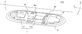
- FIG. 13 is a perspective view showing the arrangement of the U-shaped heat pipes 9 (9e, 9f) of the antenna device 101 according to the second embodiment.
- the arrangement of the U-shaped heat pipes 9 (9e, 9f) will be described with reference to FIG.
- the U-shaped heat pipes 9e and 9f have an evaporation unit 20 at the center of the heat pipe 9, and the evaporation unit 20 is arranged along the receiving antenna array 1b so as to face the X-axis direction. Further, the condensing portions 21a and 21b that release heat are arranged on the outer periphery of the antenna adapter 2 so as to face the Y-axis direction along the adjacent skirt 4.
- the condensing portions 21a and 21b of the heat pipes 9 (9e, 9f) are arranged in a direction (Y-axis direction) parallel to the traveling direction (+ Y-axis direction) of the moving body, and the evaporating portion 20 is in the traveling direction of the moving body. It is arranged in a direction (X-axis direction) perpendicular to (+ Y-axis direction). Further, at least one heat pipe 9 (9e) of the heat pipes 9 (9e, 9f) is provided by bending in the same direction (+ Y-axis direction) as the traveling direction (+ Y-axis direction) of the moving body.
- the heat pipes 9 (9f) having parts 21a and 21b and at least one of the heat pipes 9 (9e, 9f) are in the direction opposite to the traveling direction (+ Y-axis direction) (-Y-axis direction) of the moving body. It has a condensed portion 21 provided by bending.
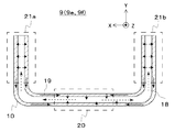
- FIG. 13 is a cross-sectional view of the U-shaped heat pipe 9 (9e, 9f) of the antenna device 101 according to the second embodiment.
- the structure of the U-shaped heat pipe 9 (9e, 9f) and the cooling mechanism will be described with reference to FIG.
- the heat pipe 9e and the heat pipe 9f are distinguished in explaining the arrangement of the U-shaped heat pipe 9, and are heat pipes having the same structure as the heat pipe 9.
- the U-shaped heat pipe 9 (9e, 9f) has two bent portions, has an evaporation portion 20 in the central portion, and has condensing portions 21a and 21b on both end portions.
- the U-shaped heat pipe 9 (9e, 9f) has a shape in which the ends of the evaporation portions 20 of the two L-shaped heat pipes 9 (FIG. 6) are joined. Therefore, the U-shaped heat pipe 9 (9e, 9f) has a configuration different from that of the L-shaped heat pipe 9 in that it has two bent portions, but other structures are the same as those of the L-shaped heat pipe 9.
- the working fluid sealed inside the U-shaped heat pipe 9 (9e, 9f) is vaporized by receiving heat from the receiving antenna array 1b at the evaporation unit 20 provided in the central portion. Since the pressure near the evaporation part 20 rises due to the vaporized working fluid 18, the vaporized working fluid 18 moves separately to the condensing parts 21a and 21b of the U-shaped heat pipe 9 (9e, 9f) having a relatively low pressure. (Dashed arrow in FIG. 13). Since the condensing portions 21a and 21b are arranged on the outer periphery of the antenna adapter 2 along the skirt 4 arranged adjacent to the antenna adapter 2, they are cooled by the running wind. Therefore, the vaporized working fluid 18 (broken line arrow in FIG.
- the U-shaped heat pipe 9 (9e, 9f) can transport heat by utilizing the ambient temperature of the U-shaped heat pipe 9 (9e, 9f). Therefore, by using the U-shaped heat pipes 9 (9e, 9f), it is possible to transport heat without the need for a pump that requires maintenance.
- the moving body is an aircraft, tilt the body when turning to obtain a bank angle.
- the apparent weight body force
- the apparent weight is generated in the -Z axis direction, so that it affects the capillary force of the liquefied working fluid 19. No volumetric force is generated.
- the heat dissipation performance is not deteriorated even when acceleration is generated in the X-axis direction.
- the condensing portions 21a and 21b are oriented in the + Y-axis direction, when acceleration is applied in the + Y-axis direction (during deceleration), the capillary force of the liquefied working fluid 19 is canceled by the body force. Therefore, the return to the evaporation unit 20 is temporarily prevented.
- the U-shaped heat pipe 9f arranged in pairs with the U-shaped heat pipe 9e since the condensing portions 21a and 21b are oriented in the ⁇ Y axis direction, acceleration is applied in the + Y axis direction (during deceleration). ), Since the body force generated in the liquefied working fluid 19 acts in the direction of promoting the recirculation, the heat transport capacity is improved as compared with the case where the body force is not generated.
- the U-shaped heat pipes 9e and 9f are arranged so that the condensing portions 21 of the U-shaped heat pipes 9e and 9f are arranged in the traveling direction of the moving body, and the condensing portions 21 of at least one heat pipe 9 are arranged in the same direction as the traveling direction of the moving body.
- the antenna device 101 shown in the second embodiment not only obtains the same effect as the antenna device 100 according to the first embodiment, but also uses more heat pipes 9 than the antenna device 100 shown in the first embodiment. Therefore, the weight of the antenna device 101 can be reduced. By reducing the weight of the antenna device 101, it is possible to reduce the fuel consumption of the moving body on which the antenna device 101 is mounted.
- At least one heat pipe 9 can operate without any problem even when the moving body accelerates and decelerates, the time required for the antenna element 13 used in the antenna device 101 to exceed the specified temperature is lengthened. This makes it possible to prolong the usable state of the antenna device 101.
- the ends of the condensing portions 21a and 21b of the U-shaped heat pipe 9e are oriented in the + Y-axis direction, and the ends of the condensing portions 21a and 21b of the U-shaped heat pipe 9f are oriented in the ⁇ Y-axis direction.
- the ends of the condensing portions 21a and 21b of the U-shaped heat pipe 9e are arranged in the ⁇ Y axis direction and the ends of the condensing portions 21a and 21b of the U-shaped heat pipe 9f are arranged in the + Y axis direction.
- the same effect as that of the first and second embodiments of the above can be obtained.
- Embodiment 3 The antenna device 102 according to the third embodiment will be described with reference to FIGS. 14 and 15.
- the same reference numerals as those in FIGS. 6 and 10 indicate the same or corresponding parts.
- the antenna device 102 of the third embodiment has a different arrangement of the heat pipes 9 (9 g, 9 h) from the antenna device 101 according to the second embodiment. Further, the description of the contents overlapping with the first embodiment and the second embodiment will be omitted.
- FIG. 14 is a perspective view showing the arrangement of U-shaped heat pipes (9 g, 9 h) of the antenna device 102 according to the third embodiment.
- the arrangement of the U-shaped heat pipe 9 (9 g, 9 h) will be described with reference to FIG.
- the evaporation sections 20a and 20b of the U-shaped heat pipe 9 (9g, 9h) are located at both ends of the heat pipe 9, and the evaporation sections 20a and 20b are arranged near the receiving antenna array 1b which is a heating element. That is, the heat pipes 9 have evaporation portions 20a and 20b on both ends, and the evaporation portions 20a and 20b are arranged so as to be along the receiving antenna array 1b so as to face the X-axis direction.
- the heat-dissipating condensing portions 21 are arranged on the outer periphery of the antenna adapter 2 so as to face the Y-axis direction along the adjacent skirts 4.
- the antenna adapter 2 in the portion where the antenna array 1 is arranged is provided with a plurality of wiring through holes 22 connecting the + Z-axis side surface and the ⁇ Z-axis side surface of the antenna adapter 2 in order to pass electrical wiring.
- the heat pipes 9e and 9f are arranged along the receiving antenna array 1b so that the thermal resistance between the heat pipes 9e and 9f is minimized, but the wiring through hole 22 is tentatively received.
- the heat pipes 9g and 9h are concentrated in the central portion of the antenna array 1b, the evaporative portions of the heat pipes 9g and 9h should be arranged directly below the receiving antenna array 1b.
- FIG. 15 is a cross-sectional view of a U-shaped heat pipe 9 (9 g, 9 h) of the antenna device 102 according to the third embodiment.
- the structure and cooling mechanism of the U-shaped heat pipe 9 (9 g, 9 h) will be described with reference to FIG.
- the heat pipe 9g and the heat pipe 9h are distinguished for explaining the arrangement of the U-shaped heat pipe 9, and are heat pipes having the same structure as the heat pipe 9.
- the U-shaped heat pipe 9 (9 g, 9h) has the same basic structure as the U-shaped heat pipe 9 (9e, 9f) of the second embodiment. However, the difference is that the condensing portion 21 is located at the center of the U-shaped heat pipe 9, and the evaporation portions 20a and 20b are located on both ends of the U-shaped heat pipe 9.
- the working fluid sealed inside the U-shaped heat pipe 9 (9 g, 9 h) is vaporized by receiving heat from the receiving antenna array 1b at the evaporation portions 20a and 20b provided on both end sides. Since the pressure near the evaporation parts 20a and 20b rises due to the vaporized working fluid 18, the vaporized working fluid 18 gathers in the condensing part 21 of the U-shaped heat pipe 9 (9g, 9h) having a relatively low pressure. (Dashed arrow in FIG. 15). Since the condensing portion 21 is arranged on the outer periphery of the antenna adapter 2 along the skirt 4 arranged adjacent to the antenna adapter 2, it is cooled by the running wind. Therefore, the vaporized working fluid 18 (broken line arrow in FIG.
- the working fluid 19 liquefied in the condensing portion 21 (solid arrow in FIG. 15) is taken into the wick 10 arranged on the inner wall of the U-shaped heat pipe 9 (9 g, 9 h).
- the liquefied working fluid 19 (solid arrow in FIG. 15) taken into the wick 10 is diffused by the capillary force of the wick 10 and flows to the evaporating portions 20a and 20b whose capillary pressure is relatively lower than that of the condensing portion 21.
- the heat pipe 9 can transport heat by utilizing the temperature around the heat pipe 9. Therefore, by using the heat pipe 9, heat can be transported without the need for a pump that requires maintenance.
- the antenna device 102 shown in the third embodiment not only obtains the same effect as the antenna device 100 according to the first embodiment, but also when the receiving antenna array 1b, which is the main cooling target, is long in the Y-axis direction. Especially effective.
- an appropriate region width is required for the condensing portion 21 of the heat pipe 9, and for example, about 1/3 to 1/4 of the total length of the heat pipe 9 is appropriate.
- the transmitting antenna array is tentatively arranged. If a heat radiating means such as a heat pipe is separately provided for cooling 1a or the control circuit 8, there is a possibility of spatial interference.
- an L-shaped heat pipe 9 is considered in combination with the U-shaped heat pipe 9 (9 g, 9h).
- the condensing portion 21 of the heat pipe 9 arranged on the + Y-axis side of the receiving antenna array 1b is bent toward the ⁇ Y-axis side, and the condensing portion 21 of the heat pipe 9 arranged on the ⁇ Y-axis side of the receiving antenna array 1b is bent.
- the weight of the antenna device 102 can be reduced.
- the L-shaped heat pipe 9 (9a to 9d) having one bend in the heat pipe 9 has been described, but the condensing portion 21 of the L-shaped heat pipe 9 is used. It may be combined and composed of a U-shaped heat pipe 9 (9 g, 9 h). That is, it has a heat pipe 9 (9a to 9d) having a condensing portion bent in the same direction as the traveling direction of the moving body and a condensing portion provided bent in the direction opposite to the traveling direction of the moving body.
- a heat pipe 9 (9 g, 9 h) configured by connecting the heat pipe 9 (9a to 9d) may be used.
- 1 Antenna array 1a Transmission antenna array, 1b Reception antenna array, 2 Antenna adapter, 3 Redome, 4 Skirt, 5, 5a, 5b, 5c, 5d, 5e, 5f Mounting bracket, 6 Power supply, 7 Moving object surface, 8 control circuit, 9 heat pipe, 9a, 9b, 9c, 9d L-shaped heat pipe, 9e, 9f, 9g, 9h U-shaped heat pipe, 10 wick, 11 through hole, 12 communication IC, 13 antenna element, 14 elastic body, 15a, 15b bolt, 16 receiving metal fitting, 17 cushioning material, 18 vaporized working fluid, 19 liquefied working fluid, 20 evaporating part, 21 condensing part, 22 wiring through hole, 23 groove, 100, 101, 102 Antenna device.
Landscapes
- Engineering & Computer Science (AREA)
- Mechanical Engineering (AREA)
- Details Of Aerials (AREA)
- Variable-Direction Aerials And Aerial Arrays (AREA)
Abstract
薄型のアンテナ装置において、メンテナンスフリーでアンテナアレイを十分に冷却できる冷却性能を確保できる。 アンテナ装置(100)は、アンテナアレイ(1)と、アンテナアダプタ(2)と、レドーム(3)と、スカート(4)と、ヒートパイプ(9)とを有する。アンテナアダプタ(2)は、通信用の電波を送信または受信するアンテナ素子(13)を有するアンテナアレイ(1)を移動体表面(7)に沿って保持する。レドーム(3)は、アンテナアダプタ(2)を覆うように配置される。スカート(4)は、レドーム(3)と移動体表面(7)との間に外気が流入しないように遮蔽し、アンテナアダプタ(2)からの熱をアンテナ装置(100)の外部へ放熱する。アンテナアダプタ(2)には、蒸発部(20)と凝縮部(21)を有するヒートパイプ(9)が、アンテナアレイ(1)からスカート(4)に向かって延びて配置される。
Description
本開示は、移動体に搭載されるアレイ式のアンテナ装置に関する。
近年、飛行機や鉄道といった移動体内でも衛星回線などを用いたインターネットサービスが利用可能になっている。移動体内で動画や画像などのコンテンツを快適に利用するためには、通信速度の向上および通信容量の大容量化が可能なアンテナ装置が必要となる。
一方、例えば航空機のような高速で移動する移動体では、燃費を削減するために空気抵抗の低減と軽量化が重要である。空気抵抗を低減するには、進行方向の前方から見た移動体の断面積(以下、投影面積という)を小さくすることや、後流の剥離を低減するために流線形状であることなどが必要となるため、移動体ではアンテナ装置の設置スペースが限定される。従来の機械駆動式のアンテナ装置では、アンテナ本体の開口面や反射板を機械的に駆動させて指向性を制御するため、機械駆動装置をアンテナ装置内に収めるのに概ね数十センチの高さが必要であった。そのため、機械駆動式のアンテナ装置を移動体に搭載する際には、空気抵抗の低減に限界があった。
そこで、アンテナ装置の薄型化を実現する手段として、フェーズドアレイ式のアンテナ装置が開発されている。フェーズドアレイ式のアンテナ装置は、複数のアンテナ素子が規則的に配列されたアンテナアレイを備え、アンテナアレイは、各アンテナ素子が送受信する信号を個別に位相制御することで指向性を電子的に制御することができ、アンテナ装置全体の薄型化が可能である。
一方、フェーズドアレイ式のアンテナ装置では、通信速度および通信容量を増大させるために、信号の高周波数化やアンテナ素子の高集積化が必要となり、従来の機械駆動式のアンテナ装置と比べて発熱密度が高くなる。また、アンテナ素子は半導体で構成されるため、所望の性能を得るためには素子を十分に冷却し、ジャンクション温度を100℃程度以下に保持させておくことが必要になる。
そこで、フェーズドアレイ式のアンテナ装置では、移動体の移動によって得られる走行風によって放熱させる手法が開発されている。例えば特許文献1では、配線基板と、複数のアンテナ素子と、複数のアンテナ素子動作モジュールと、良熱導体により構成され、配線基板の一面に所定の配列で配置された複数のアンテナ素子を収容する複数のアンテナ素子収容孔が形成されている外装板とを備える。外装板は、一面を外部空間に露出した状態で移動体の表面に取り付けられ、アンテナ素子動作モジュールにより発生した熱を配線基板及び外装板に伝達し、移動体の移動に伴い外装板の一面を流れる気流により外装板から放熱している。
一方、気流をアンテナの近くまで導くことが難しい場合、特許文献1のような構成を採用することができない。これに対して、特許文献2には、冷媒管とポンプを用いて移動体内部に放熱する装置が記載されている。
近年、飛行機や鉄道といった移動体内でも衛星回線等を用いたインターネットサービスが利用可能になっている。しかし、通信容量が少ないこともあり画像などのコンテンツを快適に扱うのは困難な状況である。
アンテナ装置の設置スペースが限られるなかで十分な通信速度を得るためには、信号の高周波数化やアンテナ素子の高集積化が必要になる。しかし発熱密度が著しく増加するため、素子の信頼性を確保する上で冷却が重要になる。
移動体が高速で移動している場合は、得られる走行風によりアンテナ装置の冷却が行われる。しかしアンテナ装置はレドームで覆われており直接外気に触れることがないため、良熱伝導材で構成されるアンテナアダプタを介して熱をアンテナ装置の外部空間まで輸送することが必要となる。
薄型のアンテナ装置ではアンテナアダプタを厚くすることができないため、アレイ中央部分の熱をアンテナアダプタでは十分に拡散させられず、十分な放熱ができないという問題があった。
そのような場合に、特許文献2は、移動体が停止している状態でも安定して放熱できるという点で優れている。しかしながら、機構部品としてポンプを使用するため、そのメンテナンスが必要であった。
そこで、本開示は、薄型のアンテナ装置の冷却性能をメンテナンスフリーで向上させることを目的としている。
本開示に係るアンテナ装置は、通信用の電波を送信または受信するアンテナ素子を有するアンテナアレイと、アンテナアレイを保持し、移動体表面と間隙を有するアンテナアダプタと、アンテナアダプタを覆うように配置されたレドームと、移動体表面とアンテナアダプタとの間隙に外気が流入しないように遮蔽するとともに、アンテナアダプタからの熱を放熱するスカートと、蒸発部と蒸発部で気化した作動流体を凝縮する凝縮部を備え、アンテナアレイからスカートに向かって延びて配置されるヒートパイプと、を備えたものである。
本開示によれば、薄型のアンテナ装置においても、メンテナンスフリーでアンテナアレイを十分に冷却できる冷却性能を確保できる。
実施の形態1.
図1は、実施の形態1に係るアンテナ装置100の外観を示す斜視図である。図2は、実施の形態1に係るアンテナ装置100の内部を示す斜視図である。図1及び図2を用いて、実施の形態1に係るアンテナ装置100の基本的な構成について説明する。
図1は、実施の形態1に係るアンテナ装置100の外観を示す斜視図である。図2は、実施の形態1に係るアンテナ装置100の内部を示す斜視図である。図1及び図2を用いて、実施の形態1に係るアンテナ装置100の基本的な構成について説明する。
図1に示すように、アンテナ装置100の表面は、レドーム3およびスカート4に囲われ、レドーム3、スカート4および移動体表面7が互いに密着している。そのため、移動体が高速で移動した際にも走行風がアンテナ装置100の内部に入り込むことはない。
図2に示すように、アンテナ装置100は、アンテナアレイ1、アンテナアダプタ2、レドーム3、スカート4、電源6、制御回路8を備える。アンテナ装置100は、航空機等の移動体表面7に取り付けられ、人工衛星を利用した通信に供されるものである。
ここで、図面において、移動体表面7と直交する方向をZ軸とし、移動体の進行方向をY軸とし、それらと直交するアンテナ装置100の幅方向をX軸とする。また以下の説明では、Z軸の正の方向を「上」、負の方向を「下」とし、Y軸の正の方向を「前」、Y軸の負の方向を「後ろ」として記す。また移動体の進行方向とは、移動体の前部から後部までを直線でつないだ方向に一致するものとし、移動体が例えば航空機であれば、機首から尾翼に向かう方向に一致するものとする。なお、実施の形態1に係る移動体は航空機として説明するが、あくまで一例であって、移動体は航空機に限れるものではない。
アンテナ装置100の各構成要素について説明する。まず、アンテナアレイ1について図2及び図3を用いて説明する。図3は、実施の形態1に係るアンテナアレイ1の概略図である。
アンテナアレイ1は、平板型の通信用モジュールであり、通信対象へ電波を送信する送信用アンテナアレイ1aと、通信対象から電波を受信する受信用アンテナアレイ1bとを備える。送信用アンテナアレイ1aと受信用アンテナアレイ1bとは、互いに間隔をあけてアンテナアダプタ2に配置される。つまり、アンテナアレイ1はアンテナアダプタ2に保持されている。なお実施の形態1に係るアンテナ装置100では、図2に示すように、受信用アンテナアレイ1bを送信用アンテナアレイ1aの-Y軸側に配置しているが、これに限ったものではなく、受信用アンテナアレイ1bが送信用アンテナアレイ1aよりも+Y軸側に配置されていても良い。また、送信用アンテナアレイ1aおよび受信用アンテナアレイ1bは、電波の送信または受信により発熱するため、互いに離れて設置される。
図3に示すように、アンテナアレイ1は、格子状に配列された複数のアンテナ素子13と、アンテナ素子13に所定の動作を実行させる通信用IC12とを備える。アンテナアレイ1は、アクティブ式の電子走査アンテナアレイであり、通信対象の人工衛星を追尾するために、各アンテナ素子13の移相量を制御することにより電波の指向性を調整する。
アンテナ素子13は、配線基板(図示なし)上に配列され、通信対象へ通信用の電波を送信または受信する。通信用の電波には、RF信号(Radio Frequency)などが使用される。そのため、アンテナ素子13は通信対象と電波を送受信する際に発熱する。アンテナ素子13はアンテナアレイ1に複数配置されるため、アンテナ素子13の高集積化によりアンテナアレイ1の発熱密度が増大するおそれがある。
なお、アンテナアレイ1に配置するアンテナ素子13の数量は、電波の走査角度、電波の損失の見込み量などによって決まる。また、各アンテナ素子13同士の間隔は、通信に使用する電波の波長によって異なる。通信に使用する電波の波長が短いほど、アンテナ素子13の素子間隔は狭くなる。例えば、通信に使用する電波の波長がKa帯のアンテナ素子13である場合、アンテナアレイ1の大きさは数十センチ角程度になる。
通信用IC12は、アンテナ素子13が配列された配線基板(図示なし)と接する面と対向する面を放熱面とし、この放熱面がアンテナアダプタ2に接合するように配置される。通信用IC12は、アンテナ素子13で送受信されるRF信号の位相を変化させる位相器や、RF信号を増幅させる増幅器などの電子部品を備える。これらの電子部品は、配線基板に実装され、電源6から必要な電源電圧を供給され、さらに、制御回路8から必要な制御信号が供給されることにより、所定の動作を実行する。通信用IC12の各電子部品は、動作時に発熱が生じる。
通信用IC12の発熱量は、電子部品の半導体プロセスによっても異なる。例えば、通信用IC12の発熱量がキロワット級である場合、通信用IC12の放熱面に接するアンテナアダプタ2の熱拡散能力が低いと、平板状である通信用IC12の中央部は十分に放熱ができない。通信用IC12が備える各電子部品は半導体素子であるため、通信用IC12が所望の性能を発揮するためにはジャンクション温度を100℃程度以下に保持しておく必要がある。ジャンクション温度とは、半導体素子が動作する最大の温度である。そのため、通信用IC12が動作するために、通信用IC12の放熱面となるアンテナアダプタ2の放熱性能が重要である。
次に、アンテナアダプタ2について、図2を用いて説明する。アンテナアダプタ2は、例えば平板状の基材であり、移動体の上面に水平に配置される。またアンテナアダプタ2は、移動体表面7との間に間隙を有し、対向している。そのためアンテナアダプタ2は、アンテナアレイ1が配置された側の面(+Z軸側面)と、移動体表面7に対向する側の面(-Z軸側面)とを有し、移動体表面7と対向する面(-Z軸側面)には、ここでは図示していないが、アンテナアレイ1に電力を供給する電源6と、アンテナアレイ1に制御信号を送信する制御回路8とが配置されている。
電源6は、移動体内から供給される電源電圧をアンテナアレイ1および制御回路8がそれぞれ必要とする電圧に変換して供給する。電源6は、複数の素子で構成されており、それぞれアンテナアダプタ2に固定されている。電源6では、変換する電力に応じて熱が生じる。
制御回路8は、アンテナアレイ1の制御を行う回路である。制御回路8には複数の電子部品が実装されており動作によって熱が生じる。
アンテナアダプタ2には、アンテナアレイ1が配置された側の面(+Z軸側面)と移動体表面7に対向する側の面(-Z軸側面)とを貫通する複数の貫通穴11が設けられている。複数の貫通穴11は、役割に応じてそれぞれ大きさが異なり、多くはアンテナアダプタ2の重量を低減させるために設けられている。そのため、アンテナアダプタ2は平板に複数の穴が設けられた骨組みとも言える。またアンテナアダプタ2の外周部に設けられた一部の貫通穴11には、取付金具5a~5fがそれぞれ嵌合する受け金具(図示せず)が設けられている。
移動体が高速で移動する際、空気抵抗によってアンテナ装置100に揚力が発生するため、アンテナアダプタ2は、例えば移動体表面7に設けられた複数の取付金具5a~5dにより固定および支持されている。複数の箇所で固定および支持されることにより、揚力によってアンテナアダプタ2の各固定部に掛かる力が分散されるようになっている。また、複数の取付金具5a~5dにより移動体表面7に固定および支持されるため、アンテナアダプタ2と移動体表面7との間には、間隙を有する。さらに、アンテナアダプタ2は、揚力によってアンテナ装置100全体が変形しないよう剛性を確保する役割も果たす。
アンテナアダプタ2は、熱伝導率の高い材料から削り出されて形成される。例えばアルミニウムなどの金属材料である。そのためアンテナアダプタ2は、アンテナアレイ1、電源6、制御回路8などで発生する熱の放熱経路となる。
レドーム3は、アンテナアダプタ2のアンテナアレイ1が配置された側の面(+Z軸側面)と間隙を有するように、アンテナアダプタ2を覆うように配置され、アンテナアレイ1を風雨や粉塵などの外乱から守る役割を果たす。レドーム3はスカート4と連続的に接続され、アンテナアダプタ2の外周部と複数のネジを用いて固定される。レドーム3の形状は流線形状である。
またレドーム3は、アンテナアレイ1が通信対象へ送受信する電波を透過させる必要があるため、通信に使用する電波の透過が可能な材料で構成される。そのためレドーム3の材料には、例えば樹脂材などの誘電率が低く電波を透過し易いものが用いられる。
この構成により、移動体が高速で移動する際にも、移動体表面7に取り付けられたアンテナ装置100に発生する空気抵抗を最小限に抑えられる。
この構成により、移動体が高速で移動する際にも、移動体表面7に取り付けられたアンテナ装置100に発生する空気抵抗を最小限に抑えられる。
スカート4は、アンテナアダプタ2の外周に沿って設けられた平板である。図2のように、例えばアンテナアダプタ2が楕円形状の場合、スカート4は中空の楕円錐台形状となる。
スカート4は、一端がレドーム3に接続され、他端が移動体表面7と接続されるため、アンテナアダプタ2と移動体表面7との間隙に外気が流入するのを防ぐ役割を果たす。スカート4と移動体表面7との接続には、例えばゴムパッキンのような弾性体14が装着され、移動体表面7と密着するように接続される。スカート4が移動体表面7と密着して設けられることにより、与圧等で移動体が膨張し、移動体表面7が撓んだ場合でもアンテナアダプタ2と移動体表面7との間隙に外気が流入するのを防いでいる。
アンテナ装置100の内部の温度に比べて外気の温度が極端に低い場合や、アンテナ装置100の内部の湿度に比べて外気の湿度が高い場合等には、アンテナ装置100の内部に結露が生じる。そのためスカート4が、レドーム3と移動体表面7とを接続する部材であることで、アンテナアダプタ2と移動体表面7との間隙に外気が流入せず、アンテナ装置100の内部に生じる結露を大幅に低減させることが可能になる。ここで外気とは、アンテナ装置100の外皮であるレドーム3、スカート4および移動体表面7で密閉された空間の外部にある空気である。すなわち、アンテナ装置100の外側の空気を指す。
なお、図2に示すように、レドーム3およびスカート4は、例えば移動体の前部と後部を結ぶ中心線A-A’方向に対して左右対称の外形である。また、送信用アンテナアレイ1aおよび受信用アンテナアレイ1bは、アンテナアダプタ2の面上に、中心線A-A’上に位置するようにそれぞれ配置されることが好ましい。このように配置することで、空力的に対称とすることができる。つまり、移動体が航空機である場合、飛行時に発生する走行風によってアンテナ装置100が受ける力学的な影響を、アンテナ装置100内において偏りなく一様に受けることが可能になる。
次に、アンテナアダプタ2の寸法制約および結合構造の一例について説明する。
アンテナアダプタ2は、アンテナ素子13等の発熱体の放熱面であり、熱伝導率の高い材料であるため、厚みを増し断面積を増やすことで熱の拡散能力を向上させることができる。すなわち、放熱面を拡大することで放熱性能を向上させることが可能である。
一方で、アンテナアダプタ2の断面積の増加は、アンテナ装置100の投影面積の増大となる。投影面積とは、移動体を進行方向の前方から見たときの移動体の断面積である。アンテナ装置100の投影面積が増大すると、移動体の空気抵抗を増大させることにつながる。またアンテナアダプタ2の厚みを増加させると、アンテナ装置100の重量の増加にもつながる。そのため、アンテナアダプタ2の厚みや断面積は、必要となる最小限の大きさにとどめておく必要がある。
また、アンテナアダプタ2と移動体表面7との結合構造については、例えば民間航空機では航空機の規格の1つであるARINC791などによって規定されている。
図4は、レドーム3の内部を上方からみた取付金具5とアンテナアダプタ2の結合構造を示す平面図である。図5は、図4のP-P’線に沿ってアンテナ装置100の一部を拡大した断面図である。図4および図5に示すように、移動体表面7に設けられた取付金具5は、ボルト15aおよび受け金具16を介してアンテナアダプタ2と結合される。そのためアンテナアダプタ2は移動体から容易に取り外すことが可能であり、故障時の点検や交換が容易となる。
アンテナアダプタ2の貫通穴11の一部には、ボルト15bを用いて受け金具16が取り付けられている。受け金具16と取付金具5とは、ボルト15aを用いて結合されている。また取付金具5と受け金具16の間には、ゴムブッシュなどの緩衝材17が介在しており、移動体内が与圧されることに起因して取付金具5の位置が変化した際にも、変化によって生じる応力を吸収する役割を果たす。航空機の規格(ARINC791やARINC792等)では、アンテナアダプタ2と移動体表面7とは8ミリメートル以上の間隔を確保するように定められている。
移動体が飛行する場合、アンテナ装置100は落雷に備えた構造も必要になる。レドーム3の表面には落雷時の電流を流す構造が設けられているものもあるが、レドーム3の内壁とアンテナ素子13との間隔が狭すぎると、放電による絶縁破壊が発生する可能性がある。そのため、アンテナアダプタ2と移動体表面7とは、概ね10数ミリの間隙があると好ましい。
これらの構造的な制約を満足しつつ、アンテナ装置100の投影面高さを例えば5センチメートル程度に抑えようとすると、アンテナアダプタ2の厚さは2センチメートル程度以下にすることが好ましい。アンテナアレイ1などの基材となるアンテナアダプタ2の大きさは搭載する機器の大きさによって変化するが、ARINC791で定めるKa帯向けのアンテナなどでは、2平方メートルを超えるような大きさになる。
次に、実施の形態1に係るアンテナ装置100の冷却について説明する。
実施の形態1に係るアンテナ装置100では、アンテナアダプタ2に設置されるアンテナアレイ1、電源6および制御回路8が発熱体となる。特に、アンテナアレイ1が主な発熱源であり、アンテナアレイ1の通信用IC12はジャンクション温度を100℃程度以下に保持させる必要がある。そのためアンテナ装置100が動作するためには、通信用IC12が設置されたアンテナアダプタ2の放熱性能の向上が必要となる。
移動体では移動によって得られる走行風(外気)をアンテナ装置100の冷却に活用することが可能である。ただし、発熱体がアンテナ装置100の走行風と接する面に設定されていなければ、走行風により直接冷却すること困難である。そのため、移動体に取り付けられたアンテナ装置100では、アンテナ装置100の周辺部に放熱器を設けることで、アンテナアダプタ2を介して放熱器から放熱することが可能となる。これにより、発熱体がアンテナ装置100の外気と接する面に設置されていなくても、アンテナ装置100を冷却することができる。
外気と熱交換を行う放熱器は表面積が大きいほど、冷却効率が高くなる。アンテナ装置100では、例えばフィンを設けた放熱器をアンテナ装置100の周辺に配置することが考えられる。一方で、移動体が航空機である場合、フィンなどの構造体はバードストライクなどの外的要因によって破壊されるおそれが高くなる。また航空機が飛行する上空では、外気温度が低く、結露などが発生しやすいため、フィン間の風路が閉塞され、熱交換効率が低下するおそれもある。外的要因や結露による熱交換効率の低下は、アンテナ装置100の冷却性能を低下させる。加えて、放熱器が移動体表面7から突出した形状である場合、空力的には圧力損失を増すこともある。そのため、移動体に取り付けるアンテナ装置の放熱器は滑らかな平板であることが望ましい。
飛行時に発生する走行風から航空機が受ける空気抵抗を最小限に抑えることが可能な放熱器としては、アンテナアダプタ2の周囲に配置されるスカート4を放熱器として活用する。つまり、アンテナアダプタ2からの熱をスカート4で放熱する。
しかしながら、スカート4は金属の平板であり、外気との間で得られる熱流束(単位時間に単位面積当を横切れる熱量)には限界がある。そのため、スカート4で高い放熱性能を得るためには、スカート4に伝える熱を予めスカート4全体に拡散しておく必要がある。一方で、アンテナ装置100に設置される発熱体は、アンテナアダプタ2を介してスカート4へ熱を拡散する。したがって、アンテナアダプタ2の熱を拡散する能力すなわち、アンテナアダプタ2の放熱能力を向上することで、アンテナアダプタ2の外周に沿って配置されたスカート4全体へ熱を拡散することが可能となる。
アンテナアダプタ2の放熱能力を向上させるためには、アンテナアダプタ2の大きさを増大させればよいが、航空機の規格等でアンテナアダプタ2の大きさに制約がある場合、アンテナアダプタ2の厚みや断面積を増加させることは難しく、スカート4へ十分に熱を拡散できないおそれがある。
例えば、2センチメートル程度の厚みのアンテナアダプタ2において、数十センチ角の通信用IC12がキロワット級の発熱をする場合、十分な熱拡散が出来ないおそれがある。スカート4へ十分に熱を拡散できないと、通信用IC12の中央部分の温度を100℃以下に下げられず、通信用IC12が所望の動作しない可能性がある。
また、通信用IC12の発熱量がキロワットに満たないような場合でも、厚さ2センチメートル程度の厚みのアンテナアダプタ2では放熱面であるスカート4までの熱抵抗を少しでも小さくする必要がある。
上述のとおり、アンテナ装置100の発熱体で発生した熱は大部分がアンテナアダプタ2を介して伝熱され、スカート4を放熱面として外気に放熱されるが、アンテナアダプタ2の厚みが薄い場合には、十分な放熱性を確保できないおそれがある。特にアンテナアダプタ2の中央部に配置されるアンテナアレイ1は、周囲に他の発熱体が配置されていることも有り有効な放熱経路が少なく、熱が籠る。
そこで、実施の形態1に係るアンテナ装置100では、アンテナアダプタ2に熱輸送能力が高いヒートパイプ9を設ける。
次に、実施の形態1に係るヒートパイプ9について説明する。
まず、図6、図7および図8を用いて、ヒートパイプ9の配置について説明する。図6は、図2に示すアンテナ装置100において、アンテナアダプタ2を透過して示した斜視図である。また、図7は図6のアンテナ装置100のA-A’断面を示す断面図であり、図8は図6のアンテナ装置100のB-B’断面を示す断面図である。
図示はしていないが、制御回路8、電源6、アンテナアレイ1は電気配線で結ばれている。図7に示すように、アンテナアダプタ2の対向する面(+Z軸側面および-Z軸側面)に制御回路8および電源6とアンテナアレイ1はそれぞれ配置されているため、アンテナアダプタ2のアンテナアレイ1が接合されている部分には、電気配線を通すための+Z軸側面と-Z軸側面を結ぶ配線用貫通孔22が複数設けられている。そのためヒートパイプ9(9a~9d)は配線用貫通孔22と干渉しないように、アンテナアレイ1を囲うように、アンテナアダプタ2に配置される(図6)。アンテナアダプタ2に設置されたアンテナアレイ1のうち、発熱密度の高い一方にのみヒートパイプ9を配置してもよい。図6では、受信用アンテナアレイ1bを挟むようにヒートパイプ9を配置した例を示したが、配置例はこれに限定されるものではない。
ここで、ヒートパイプ9(9a~9d)は屈曲部を有し、その形状はL字型などである。ただし、ヒートパイプ9(9a~9d)は屈曲する部分を備えればよく、L字型に限定されるものではない。
ここで、ヒートパイプ9(9a~9d)は屈曲部を有し、その形状はL字型などである。ただし、ヒートパイプ9(9a~9d)は屈曲する部分を備えればよく、L字型に限定されるものではない。
ヒートパイプ9(9a~9d)の詳細は後述するが、銅、銅合金などの熱伝導性が高い材質からなるパイプ中に揮発性の作動流体を封入したものであり、発熱体の熱により作動流体を気化する蒸発部20と、気化した作動流体を凝縮する凝縮部21とを備える。作動流体が蒸発部20で蒸気となり、凝縮部21に移動して凝縮することで熱を効率的に移動させることが可能である。凝縮した液は再び蒸発部20に戻るようにされる。
ヒートパイプ9(9a~9d)は、ヒートパイプ9の蒸発部20がアンテナアレイ1側に、凝縮部21がスカート4側に向くように、アンテナアレイ1からスカート4に向かって延びて配置される。図6では、それぞれのヒートパイプ9(9a~9d)は、蒸発部20が受信用アンテナアレイ1bに沿うようにX軸方向を向き、熱を放出する凝縮部21がアンテナアダプタ2の外周に、隣接配置されるスカート4に沿うようY軸方向を向くように配置される。さらに、凝縮部21が移動体の進行方向と垂直を成す向きに配置され、凝縮部21が移動体の進行方向に沿うように配置されるとよい。図6では、ヒートパイプ9aおよびヒートパイプ9bはヒートパイプの凝縮部端が+Y軸方向を向き、ヒートパイプ9cおよびヒートパイプ9dはヒートパイプの凝縮部端が-Y軸方向を向くように配置される。なお、移動体の進行方向に沿うように配置するとは、凝縮部21が移動体の進行方向に平行を成す向きに配置されること、または、凝縮部21が移動体の進行方向より傾いた角度に配置されることを含む。
アンテナ装置100は空気抵抗を減らすためには高さ方向に低い方が良く、また軽量であることが望まれる。アンテナアダプタ2には飛行時に受ける揚力に耐えられる十分な強度が求められるが、仮にアンテナアダプタ2の厚みが2センチメートル程度あるのならば、ヒートパイプ9(9a~9d)をアンテナアダプタ2の表面に配置することも可能である。しかしながら、アンテナアレイ1と通信対象である人工衛星との間の通信電波を遮蔽しないこと、および、機器間の電気配線や絶縁を阻害しないことなどを考えると、アンテナアダプタ2の内部に配置することが望ましい(図7、図8)。図7および図8では、ヒートパイプ9(9a~9d)が、アンテナアダプタ2の内部であってアンテナアダプタ2の厚み内に配置された例を示している。ヒートパイプ9(9a~9d)をアンテナアダプタ2の内部に配置するには、アンテナアダプタ2に溝23を設け、溝23に沿って設置することが考えられる。
また、ヒートパイプ9(9a~9d)がアンテナアダプタ2の面内に沿って、アンテナアダプタ2の内部に配置される例を説明したが、アンテナアダプタ2の厚みに収まる範囲内でヒートパイプ9(9a~9d)を傾けて配置してもよい。たとえば、図9に示すように、ヒートパイプ9aおよびヒートパイプ9bの凝縮部21が位置する端部を+Z方向にアンテナアダプタ2の厚み内に収まるまで傾け、ヒートパイプ9aおよびヒートパイプ9bの蒸発部20が位置する部分を-Z方向にアンテナアダプタ2の厚み内に収まるまで傾ける。同様に、ヒートパイプ9cおよびヒートパイプ9dの凝縮部21が位置する端部を+Z方向にアンテナアダプタ2の厚み内に収まるまで傾け、ヒートパイプ9aおよびヒートパイプ9bの蒸発部20が位置する部分を-Z方向にアンテナアダプタ2の厚み内に収まるまで傾ける(図9)。つまり、ヒートパイプ9(9a~9d)の凝縮部21が蒸発部20より上側となるように配置してもよい。
また、ヒートパイプ9(9a~9d)の蒸発部は発熱体であるアンテナアレイ1の近くに配置する方が、熱輸送効率が良くなる。アンテナアレイ1が配置されている部分のアンテナアダプタ2には、電気配線を通すためにアンテナアダプタ2の+Z軸側面と-Z軸側面を結ぶ配線用貫通孔22が複数設けられているため、ヒートパイプ9(9a~9d)をアンテナアレイ1の直下に配置することは困難な場合が多い。そのため図6では、ヒートパイプ9(9a~9d)は受信用アンテナアレイ1bとの間の熱抵抗が最小になるように受信用アンテナアレイ1bに沿うように配置した例を示している。仮に配線用貫通孔22が受信用アンテナアレイ1bの中央部分に集中しているような場合は、ヒートパイプ9(9a~9d)の蒸発部は受信用アンテナアレイ1bの直下に配置することが望ましい。
したがって、ヒートパイプ9(9a~9d)はアンテナアダプタ2の内部で、かつ、アンテナアレイ1の真下に配置されることが最も望ましい配置例である。このようにヒートパイプ9(9a~9d)を配置することで、発熱体からの熱輸送効率が向上し、アンテナアダプタ2の放熱性能を向上させることできる。アンテナアダプタ2の放熱性能の向上に伴い、アンテナ装置100の放熱器となるスカート4にて効率よく熱を外部へ放出することが可能となる。
次に、ヒートパイプ9の構造および冷却の仕組みについて説明する。図10はヒートパイプ9(9a~9d)の断面模式図である。図10を用いて、ヒートパイプ9の構造および冷却の仕組みについて説明する。なお、ヒートパイプ9a~9dは、ヒートパイプ9の配置を説明する上で区別したものであって、ヒートパイプ9と同じ構造のヒートパイプ9である。
ヒートパイプ9は、いわゆるウィック型のヒートパイプ9であり、パイプの壁面にはウィック10が設けられている。ウィック10は、毛細管構造であり、液体の毛細管現象を利用して凝縮部21で液化した作動流体を蒸発部20に戻すことができる。
ヒートパイプ9の内部には作動流体が封じられている。作動流体は蒸発潜熱が大きいほど熱輸送能力が高いため一般的には水が良く使われる。ただし、水は氷点下で凍結する。そのため、作動流体に水を用いた場合、ヒートパイプ9の温度が氷点下になると水が結露し膨張することでヒートパイプ9を破損してしまうおそれがある。
アンテナ装置100が航空機に搭載された場合、上空では氷点下50℃程度の外気に曝されるため、仮にアンテナアレイ1が発熱していないような場合にはヒートパイプ9が氷点下まで冷やされてしまうこともある。そのため、作動流体に水を用いる場合にはヒーターなどの加熱装置をヒートパイプ9の周辺に取り付けておいてもよい。また、ヒートパイプ9を使用する環境の温度が氷点下になる場合は、アンモニアやエタノール等を含んだ氷点下でも凍結をしない液体を作動流体に用いてもよい。すなわち、アンテナ装置100が使用される環境において、凍結しない液体を作動流体としてもよい。
ヒートパイプ9の内部には作動流体が封じられている。作動流体は蒸発潜熱が大きいほど熱輸送能力が高いため一般的には水が良く使われる。ただし、水は氷点下で凍結する。そのため、作動流体に水を用いた場合、ヒートパイプ9の温度が氷点下になると水が結露し膨張することでヒートパイプ9を破損してしまうおそれがある。
アンテナ装置100が航空機に搭載された場合、上空では氷点下50℃程度の外気に曝されるため、仮にアンテナアレイ1が発熱していないような場合にはヒートパイプ9が氷点下まで冷やされてしまうこともある。そのため、作動流体に水を用いる場合にはヒーターなどの加熱装置をヒートパイプ9の周辺に取り付けておいてもよい。また、ヒートパイプ9を使用する環境の温度が氷点下になる場合は、アンモニアやエタノール等を含んだ氷点下でも凍結をしない液体を作動流体に用いてもよい。すなわち、アンテナ装置100が使用される環境において、凍結しない液体を作動流体としてもよい。
したがって、航空機に取り付けられたアンテナ装置100の場合、飛行時に低温環境で使用されることが予測されるため、ヒートパイプ9の作動流体には使用環境下で凍結しない液体を使用することが望ましい。
ヒートパイプ9の内部に封じられた作動流体は、蒸発部20で熱を受けて気化する。気化した作動流体18により蒸発部20付近の圧力が上昇するため、相対的に圧力が低い凝縮部21に気化した作動流体18が運ばれる(図10の破線矢印)。凝縮部21は蒸発部20に比べて外気に近いに配置されており、外気により冷やされる。そのため、蒸発部20から移動してきた気化した作動流体18(図10の破線矢印)は、凝縮部21において冷やされて液化する。凝縮部21にて液化した作動流体19(図10の実線矢印)はヒートパイプ9の内壁に配置されたウィック10に取り込まれる。ウィック10に取り込まれた液化した作動流体19(図10の実線矢印)はウィック10の毛細管力によって拡散し、凝縮部21と比べ相対的に毛細管力の低い蒸発部20へと還流される。以後、ヒートパイプ9の液化した作動流体19が蒸発部20にて気化され、凝縮部21に運ばれ、凝縮部21にて液化され、蒸発部20に還流されることを還流サイクルと呼ぶこととする。
このように、ヒートパイプ9はヒートパイプ9の周囲の温度を利用して、熱を輸送することができる。そのため、ヒートパイプ9を用いることで、メンテナンスが必要なポンプを要しないで熱を輸送することが可能となる。
このように、ヒートパイプ9はヒートパイプ9の周囲の温度を利用して、熱を輸送することができる。そのため、ヒートパイプ9を用いることで、メンテナンスが必要なポンプを要しないで熱を輸送することが可能となる。
実施の形態1に係るアンテナ装置100では、ヒートパイプ9は、アンテナアレイ1からスカート4に向かって延びて配置される。すなわち、ヒートパイプ9の蒸発部20が発熱体であるアンテナアレイ1の近くに配置され、ヒートパイプ9の凝縮部21が外気と熱交換するスカート4の近くに配置される。これにより、ヒートパイプ9の作動流体はアンテナアレイ1から受熱し、ヒートパイプ9の作動流体が気化する。気化した作動流体18は、蒸発部20より低温である凝縮部21に運ばれ、凝縮部21にて液化される。液化した作動流体19は、ヒートパイプ9の壁面の設けられたウィック10の毛細管力によって、蒸発部20へ戻る。ヒートパイプ9が、発熱体の熱をアンテナアダプタ2中央部からスカート4が設けられている外周部に運ぶことで、アンテナアダプタ2の放熱性能の向上につながる。すなわち、ヒートパイプ9を設けることでアンテナアダプタ2の熱の拡散効率を向上できる。
また、実施の形態1に係るアンテナ装置100では、ヒートパイプ9がアンテナアダプタ2に設けられた溝23に沿って配置されるため、アンテナアダプタ2の大きさを増大させずに、発熱体からの熱をスカート4の全体に向かって拡散することが可能となる。
したがって、アンテナ装置100にヒートパイプ9を設けることにより、アンテナアダプタ2の大きさを増大させずに、かつ、メンテナンスフリーで、アンテナアダプタ2の熱をスカート4へ運ぶことができる。すなわち、アンテナアダプタ2の放熱性能を向上により、スカート4全体へ熱を拡散でき、アンテナ装置100の冷却が向上する。
次に、実施の形態1に係るヒートパイプ9の熱輸送能力について説明する。
通常、ヒートパイプ9の熱輸送では毛細管力による液化した作動流体19の還流性能(ウィック限界)がボトルネックとなる。ヒートパイプ9の最大熱輸送量Qは式(1)で示される。

ここでMはメリット数と呼ばれる作動流体の特性に依存する項である。右辺第二項はウィック特性に依存する項であり、Kはウィックの浸透圧係数、rcはウィック半径である。右辺第三項は寸法に依存する項であり、Awはウィックの断面積、leffはヒートパイプ9の有効長である。第四項目が体積力に依存する項であり、gは重力加速度、σは表面張力、ρlは密度、βはヒートパイプ9の傾きである。
ヒートパイプ9では作動流体の還流サイクルが動作している状態では、熱輸送能力は非常に高く、潜熱量も多く、常温域で最も熱輸送能力を発揮する水を作動流体に用いた場合では、良熱導体として知られているアルミニウムや銅の熱伝導率と比較しても1桁から2桁高い熱伝導性能が得られる。また、氷点下でも凍結しない液体であるエタノールを作動流体に用いた場合でも、良熱導体として知られているアルミニウムや銅の熱伝導率よりも高い熱伝導性能が得られる。
たとえば、アンテナ装置100に設置されるヒートパイプ9の等価熱伝導率が5000W/mK程度であったと仮定すると、ヒートパイプ9を約4本用いることで受信用アンテナアレイ1bとスカート4との間の熱抵抗を3割程度下げることが出来る。そのためキロワット級の発熱がある場合において、航空機の飛行高度が低く、外気温度が高い場合でも受信用アンテナアレイ1bの中央部分の温度を目標値以下に保つことが可能になる。
アンテナアダプタ2に配置するヒートパイプ9の本数を4本よりも増やすことで、機器の温度をより低く保つことは可能になる。しかし、航空機に設置されるアンテナ装置100では、ヒートパイプ9の設置スペースに限りがあり、また、本数の増加に伴いコストも高くなるため、限られた本数のヒートパイプ9で最大限の放熱性能を出すことが重要になる。
アンテナアダプタ2に配置するヒートパイプ9の本数を4本よりも増やすことで、機器の温度をより低く保つことは可能になる。しかし、航空機に設置されるアンテナ装置100では、ヒートパイプ9の設置スペースに限りがあり、また、本数の増加に伴いコストも高くなるため、限られた本数のヒートパイプ9で最大限の放熱性能を出すことが重要になる。
一方、ヒートパイプ9は作動流体の還流サイクルが滞り、蒸発部20に液化した作動流体19が戻ってこない、いわゆるドライアウト状態になると、熱伝導はヒートパイプ9のパイプ材の伝導のみになるため、熱輸送能力が急激に低下してしまうことがある。液化した作動流体19の還流を妨げる要因に、液化した作動流体19にかかる体積力(見かけの重さ)が毛細管力を打ち消してしまう事象が挙げられる。
たとえば、直線状のヒートパイプが重力方向に沿って設置されているとする(図示なし)。ヒートパイプの凝縮部が蒸発部よりも重力方向に高い位置にあるボトムヒートの場合は、重力による体積力は還流を助ける方に働く。一方で、凝縮部が蒸発部よりも重力方向に低い位置にあるトップヒートの場合は、重力による体積力はウィック10の毛細管力に逆らう向きに働き、作動流体の還流を妨げることになる。このように作動流体の還流が妨げられることが、ドライアウト状態の発生原因となり得る。ヒートパイプの構造にもよるが、通常は1G(=9.81 m/s2)程度の加速度が液化した作動流体の還流を妨げる向きにかかると、ドライアウトが発生する可能性が非常に高くなる。
ここで、図6に示すようにヒートパイプ9が設けられたアンテナ装置100が、航空機に搭載される場合について考える。航空機の衛星通信アンテナは主に機内エンターテイメント向けに供されるため、離発着時に用いられることは少なく、概ね上空での巡航時に稼働する。厳密にいえば航空機は上空での巡航時も機首を3度程度上げて飛行しているが、ここでは簡単にするため航空機の機体がXY平面と平行である(迎角0度)と仮定する。このとき、航空機が巡航(水平慣性飛行)している際の重力方向は-Z軸方向と考えられる。
航空機が水平慣性飛行をしている場合は、ヒートパイプ9(9a~9d)はXY平面に配置されている限り液化した作動流体19は体積力の影響を受けることがないため、液化した作動流体19は毛細管力によって還流される。そのため、全てのヒートパイプ9(9a~9d)は期待される熱輸送能力を発揮できる。
一方、航空機が加速および減速をしている場合や、機首を大きく持ち上げている場合(機体の仰角が大きな場合)には、ヒートパイプ9(9a~9d)の液化した作動流体19には体積力が発生する。特に、加速および減速時にはY軸方向に大きな加速度がかかることになる。加速時は-Y軸方向に加速度がかかり、減速時は+Y軸方向に加速度がかかる。
高い加速性能が求められる戦闘機やレーシングカーなどの移動体では加速度は1Gを超過するが、快適性を求められる旅客機など移動体の場合でも0.5G程度の加速度は発生する。つまり移動体の加速および減速時にはヒートパイプ9(9a~9d)の配置向きによってはドライアウトが発生する可能性が高い。
高い加速性能が求められる戦闘機やレーシングカーなどの移動体では加速度は1Gを超過するが、快適性を求められる旅客機など移動体の場合でも0.5G程度の加速度は発生する。つまり移動体の加速および減速時にはヒートパイプ9(9a~9d)の配置向きによってはドライアウトが発生する可能性が高い。
航空機の加速および減速時に、アンテナアダプタ2に設置してある4本のヒートパイプ9(9a~9d)全てがドライアウトを起こすと、アンテナアレイ1の温度は上昇を始める。一般的には、移動体において加減速が行われる時間は数秒から長くても数分であるが、その間にアンテナアレイ1の温度が急激に上昇し、ジャンクション温度が許容値を超えると機器の寿命低下や故障発生につながる可能性がある。
そこで、実施の形態1に係るアンテナ装置100では、図6に示すように、ヒートパイプ9(9a~9d)は屈曲部を有する。図6では、蒸発部20は受信用アンテナアレイ1bに沿うようにX軸方向を向くように配置され、凝縮部21はスカート4に沿うようY軸方向を向くように配置される。詳しく説明すると、ヒートパイプ9aおよびヒートパイプ9bは、蒸発部20がX軸方向を向いており、凝縮部21が+Y軸方向を向くように配置される。ヒートパイプ9cおよびヒートパイプ9dは、蒸発部20がX軸方向を向いており、凝縮部21が-Y軸方向を向くように配置される。つまり、ヒートパイプ9(9a~9d)の凝縮部21は移動体の進行方向(+Y軸方向)と平行を成す向き(Y軸方向)に配置され、蒸発部20は移動体の進行方向(+Y軸方向)と垂直を成す向き(X軸方向)に配置される。また、ヒートパイプ9(9a~9d)のうち少なくとも1本のヒートパイプ9(9a、9b)は、移動体の進行方向(+Y軸方向)と同じ方向(+Y軸方向)に屈曲して設けられた凝縮部21を有し、ヒートパイプ9(9a~9d)のうち少なくとも1本のヒートパイプ9(9c、9d)は、移動体の進行方向(+Y軸方向)と逆方向(-Y軸方向)に屈曲して設けられた凝縮部21を有する。図6では、ヒートパイプ9a、9bが第一ヒートパイプに相当し、ヒートパイプ9c、9dが第二ヒートパイプに相当する。
図6のようにヒートパイプ9(9a~9d)が配置されたアンテナ装置100を搭載する航空機が加速する場合について説明する。航空機が加速する場合は、-Y方向に加速度が発生する。そのため、ヒートパイプ9(9a~9d)のX軸方向を向いている蒸発部20部位では、作動流体は体積力の影響を受けない。つまり、屈曲部を有するヒートパイプ9(9a~9d)において、移動体の進行方向(+Y軸方向)に対して垂直をなす向き(X軸方向)に配置された部分は、加速時には体積力の影響を受けない。
一方で、ヒートパイプ9(9a~9d)のY軸方向を向いている部位では、加速度が発生する向きと作動流体の還流方向によって、体積力による影響を受ける可能性がある。屈曲部を有するヒートパイプ9(9a~9d)において、移動体の進行方向(+Y軸方向)と平行を成す向き(Y軸方向)に配置された部分は、加速時には体積力の影響を受ける可能性がある。
ヒートパイプ9cおよびヒートパイプ9dの凝縮部21のように、加速度が-Y方向に発生しており、作動流体が+Y方向に還流する場合、すなわち加速度の発生方向と作動流体の還流方向が逆方向の場合、体積力より一時的に作動流体の還流が妨げられることになる。一方で、ヒートパイプ9aおよびヒートパイプ9bの凝縮部21のように、加速度が-Y方向に発生しており、作動流体が-Y方向に還流する場合、すなわち加速度の発生方向と作動流体の還流方向が同一方向の場合、体積力が作動流体の還流を促進することになる。ヒートパイプ9cおよびヒートパイプ9dは体積力により還流を一時的に妨げられるが、ヒートパイプ9aおよびヒートパイプ9bでは、体積力により還流が促進されるため、ヒートパイプ9(9a~9d)全体での放熱性能は低下しない。
したがって、図6のようにヒートパイプ9(9a~9d)が配置されたアンテナ装置100では、移動体が加速した場合であっても、少なくとも2本のヒートパイプ9が作動し続けるため、受信用アンテナアレイ1bは短時間でジャンクション温度が規定値を超えてしまうような急激な温度上昇を起こすことはない。つまり、加速時においてもヒートパイプ9がドライアウトを起こさず、アンテナアダプタ2の熱をスカート4へ放熱し続けることが可能となる。
また、図6のようにヒートパイプ9(9a~9d)が配置されたアンテナ装置100を搭載する航空機が減速する場合について説明する。航空機が減速する場合は、+Y方向に加速度が発生する。そのため、ヒートパイプ9(9a~9d)のX軸方向を向いている部位では、作動流体は体積力の影響を受けない。つまり、X軸方向に向くように配置されたヒートパイプ9(9a~9d)の蒸発部20の作動流体は体積力の影響を受けない。言い換えると、屈曲部を有するヒートパイプ9において、移動体の進行方向(+Y軸方向)に対して垂直をなす向き(+X軸方向)に配置された部分は、減速時にも体積力の影響を受けない。
一方で、ヒートパイプ9(9a~9d)のY軸方向を向いている部位では、加速度が発生する向きと作動流体の還流方向によって、体積力による影響を受ける可能性がある。屈曲部を有するヒートパイプ99(9a~9d)において、移動体の進行方向(+Y軸方向)と平行を成す向き(Y軸方向)に配置された部分は、減速時にも体積力の影響を受ける可能性がある。
ヒートパイプ9aおよびヒートパイプ9bの凝縮部21のように、加速度が+Y方向に発生しており、作動流体が-Y方向に還流する場合、すなわち加速度の発生方向と作動流体の還流方向が逆方向の場合、体積力より一時的に作動流体の還流が妨げられることになる。一方で、ヒートパイプ9cおよびヒートパイプ9dの凝縮部21のように、加速度が+Y方向に発生しており、作動流体が+Y方向に還流する場合、すなわち加速度の発生方向と作動流体の還流方向が同一方向の場合、体積力が作動流体の還流を促進することになる。ヒートパイプ9aおよびヒートパイプ9bは体積力により還流を一時的に妨げられるが、ヒートパイプ9cおよびヒートパイプ9dでは、体積力により還流が促進されるため、放熱性能は低下しない。
したがって、図6のようにヒートパイプ9(9a~9d)が配置されたアンテナ装置100では、移動体が減速した場合であっても、少なくとも2本のヒートパイプ9が作動し続けるため、受信用アンテナアレイ1bは短時間でジャンクション温度が規定値を超えてしまうような急激な温度上昇を起こすことはない。つまり、減速時においてもヒートパイプ9がドライアウトを起こさず、アンテナアダプタ2の熱をスカート4へ放熱し続けることが可能となる。
以上のように、実施の形態1におけるアンテナ装置100は、アンテナアダプタ2において屈曲部を有するヒートパイプ9(9a~9d)をアンテナアレイ1からスカート4に向かって延びて配置することにより、薄型のアンテナ装置100においてもメンテナンの必要なく、アンテナアダプタ2の放熱性能の向上ができるため、アンテナアレイ1を十分に冷却できる。
すなわち、アンテナアダプタ2において、ヒートパイプ9(9a~9d)の蒸発部20が受信用アンテナアレイ1bに沿うようにX軸方向を向き、凝縮部21がスカート4に沿うようY軸方向を向いて設置されることにより、アンテナアダプタ2のサイズを増加させることなく、アンテナアダプタ2からスカート4へ効率よく熱を伝熱することができる。その結果、アンテナ装置100の冷却性能を向上させることが可能となる。
アンテナアダプタ2のサイズを増加させる必要ないため、薄型のアンテナ装置100にも適用できる。また、アンテナ装置100を薄型化することが可能となり、重量が削減され、移動体の燃費改善も可能となる。
また、アンテナアダプタ2の熱を放熱器であるスカート4に効率よく伝えることができるため、アンテナアダプタ2の中央部に発熱体であるアンテナアレイ1等が設置されても放熱することができる。通信容量が増加し、アンテナアダプタ2の中央部にて発熱密度が高くなった場合でも、アンテナアレイ1が動作する温度まで冷却することができるため、アンテナアレイ1を規定の温度以下に保つことが可能になる。
薄型のアンテナ装置100において発熱体が外気と直接熱交換できない場合、すなわち、発熱体がアンテナアダプタ2の中央部に配置される場合であっても、実施の形態1の構成とすることでアンテナ装置100の冷却性能を向上することができる。
さらに、移動体が航空機である場合、巡航(水平慣性飛行)、加速および減速など状況が考えられるが、少なくとも一つのヒートパイプ9の凝縮部21の端が+Y軸方向を向いており、少なくとも一つのヒートパイプ9の凝縮部21の端が-Y軸方向を向いていることで、アンテナ装置100の冷却性能を保つことができる。また、移動体が運航に必要な短時間の加速や減速を行っても、アンテナ装置100に搭載された全てのヒートパイプ9がドライアウトを起こすことがなく、アンテナアレイ1を規定の温度以下に保つことが可能になる。これにより、移動体が加速および減速している間も冷却性能を確保することできるため、通信サービスの提供を安定して行うことが可能になる。
次に、実施の形態1に係るアンテナ装置100の変形例について説明する。
図11は、実施の形態1に係るアンテナ装置100の変形例のアンテナ装置100をZ軸方向からみた断面図である。本開示の変形例は、実施の形態1に係るアンテナアダプタ2の形状およびヒートパイプ9(9a~9d)の形状を変形したものである。
実施の形態1では、アンテナアダプタ2の形状は楕円型や小判型であり、ヒートパイプ9(9a~9d)の屈曲は90度を例に挙げ説明を行った。しかしながら、航空機などのように進行方向が決まっている移動体にアンテナ装置100が搭載される場合は、空気抵抗をより低減するため、例えばアンテナアダプタ2の後方が絞られた雫型の形状の場合もある。
このような場合では、ヒートパイプ9(9a~9d)の凝縮部21側をスカート4に接するように配置すると、ヒートパイプ9(9a~9d)の凝縮部21側はY軸方向には沿わず、ヒートパイプ9の屈曲は90度とは異なる角度となる。しかしながら、アンテナアダプタ2に設置されるヒートパイプ9(9a~9d)のうち、少なくとも一つのヒートパイプ9は凝縮部21の端が+Y軸方向を向いており、少なくとも一つのヒートパイプ9はヒートパイプ9の凝縮部21の端が-Y軸方向を向いていれば、実施の形態1のアンテナアダプタ2の形状やヒートパイプ9の屈曲する角度が異なっても、実施の形態1に係るアンテナ装置100と同様の効果が得られる。
また、説明においては、ヒートパイプ9aおよびヒートパイプ9bはヒートパイプ9の凝縮部21の端が+Y軸方向を向いており、ヒートパイプ9cおよびヒートパイプ9dはヒートパイプ9の凝縮部21の端が-Y軸方向を向いているとして説明を行ったが、受信用アンテナアレイ1bのY軸方向の長さが十分に長い場合などは、ヒートパイプ9aおよびヒートパイプ9bはヒートパイプ9の凝縮部21の端が-Y軸方向を、ヒートパイプ9cおよびヒートパイプ9dはヒートパイプ9の凝縮部21の端が+Y軸方向を向くように配置しても同様の効果が得られる。
さらに、ヒートパイプ9の本数は4本として説明を行ったが、コスト的に余裕があればヒートパイプ9の本数を増やし、また、設置スペースに余裕があれば、アンテナアダプタ2に搭載されている送信用アンテナアレイ1aや制御回路8などの周辺にヒートパイプ9を配置してもよい。ヒートパイプ9の設置する本数を増やすことで、実施の形態1に係るアンテナ装置100が得られる効果だけでなく、さらに冷却性能の向上が期待できる。
実施の形態2.
実施の形態2におけるアンテナ装置100について図12および図13を用いて説明する。なお、図12および図13中、図6および図10と同一符号は同一又は相当部分を示す。実施の形態2は、実施の形態1に係るアンテナ装置100のヒートパイプ9が屈曲部を2か所有する構成にしたものである。以後、実施の形態2に係るヒートパイプ9をU字型ヒートパイプと呼ぶことにする。また、実施の形態1と重複する内容は記載を省略する。
実施の形態2におけるアンテナ装置100について図12および図13を用いて説明する。なお、図12および図13中、図6および図10と同一符号は同一又は相当部分を示す。実施の形態2は、実施の形態1に係るアンテナ装置100のヒートパイプ9が屈曲部を2か所有する構成にしたものである。以後、実施の形態2に係るヒートパイプ9をU字型ヒートパイプと呼ぶことにする。また、実施の形態1と重複する内容は記載を省略する。
図13は、実施の形態2に係るアンテナ装置101のU字型ヒートパイプ9(9e、9f)の配置を示す斜視図である。図13を用いて、U字型ヒートパイプ9(9e、9f)の配置について説明する。
U字型ヒートパイプ9eおよび9fはヒートパイプ9の中央部に蒸発部20を有し、蒸発部20は受信用アンテナアレイ1bに沿うようにX軸方向を向いて配置される。また熱を放出する凝縮部21aおよび21bはそれぞれアンテナアダプタ2の外周に、隣接して配置されるスカート4に沿うようY軸方向を向いて配置されている。
つまり、ヒートパイプ9(9e、9f)の凝縮部21aおよび21bは移動体の進行方向(+Y軸方向)と平行を成す向き(Y軸方向)に配置され、蒸発部20は移動体の進行方向(+Y軸方向)と垂直を成す向き(X軸方向)に配置される。また、ヒートパイプ9(9e、9f)のうち少なくとも1本のヒートパイプ9(9e)は、移動体の進行方向(+Y軸方向)と同じ方向(+Y軸方向)に屈曲して設けられた凝縮部21aおよび21bを有し、ヒートパイプ9(9e、9f)のうち少なくとも1本のヒートパイプ9(9f)は、移動体の進行方向(+Y軸方向)と逆方向(-Y軸方向)に屈曲して設けられた凝縮部21を有する。
U字型ヒートパイプ9eおよび9fはヒートパイプ9の中央部に蒸発部20を有し、蒸発部20は受信用アンテナアレイ1bに沿うようにX軸方向を向いて配置される。また熱を放出する凝縮部21aおよび21bはそれぞれアンテナアダプタ2の外周に、隣接して配置されるスカート4に沿うようY軸方向を向いて配置されている。
つまり、ヒートパイプ9(9e、9f)の凝縮部21aおよび21bは移動体の進行方向(+Y軸方向)と平行を成す向き(Y軸方向)に配置され、蒸発部20は移動体の進行方向(+Y軸方向)と垂直を成す向き(X軸方向)に配置される。また、ヒートパイプ9(9e、9f)のうち少なくとも1本のヒートパイプ9(9e)は、移動体の進行方向(+Y軸方向)と同じ方向(+Y軸方向)に屈曲して設けられた凝縮部21aおよび21bを有し、ヒートパイプ9(9e、9f)のうち少なくとも1本のヒートパイプ9(9f)は、移動体の進行方向(+Y軸方向)と逆方向(-Y軸方向)に屈曲して設けられた凝縮部21を有する。
図13は、実施の形態2に係るアンテナ装置101のU字型ヒートパイプ9(9e、9f)の断面図である。図13を用いて、U字型ヒートパイプ9(9e、9f)の構造および冷却の仕組みについて説明する。なお、ヒートパイプ9eおよびヒートパイプ9fは、U字型ヒートパイプ9の配置を説明する上で区別したものであって、ヒートパイプ9と同じ構造のヒートパイプである。
U字型ヒートパイプ9(9e、9f)は屈曲部を2か所有し、中央部に蒸発部20を備え、両端部側に凝縮部21aおよび21bを備える。U字型ヒートパイプ9(9e、9f)は、2本のL字型ヒートパイプ9(図6)の蒸発部20の端が結合された形である。そのため、U字型ヒートパイプ9(9e、9f)は屈曲部を2か所有する点でL字型ヒートパイプ9と構成が異なるが、その他の構造はL字型ヒートパイプ9と同じである。
U字型ヒートパイプ9(9e、9f)の内部に封じられた作動流体は、中央部に設けられた蒸発部20にて受信用アンテナアレイ1bから熱を受けることにより気化する。気化した作動流体18により蒸発部20付近の圧力は上昇するため、相対的に圧力の低いU字型ヒートパイプ9(9e、9f)の凝縮部21aおよび21bに気化した作動流体18は分かれて移動する(図13の破線矢印)。凝縮部21aおよび21bはアンテナアダプタ2の外周に、隣接して配置されるスカート4に沿うように配置されているため、走行風によって冷やされる。そのため、蒸発部20から移動してきた気化した作動流体18(図13の破線矢印)は、凝縮部21aおよび21bにおいて冷やされ液化する。凝縮部21aおよび21bにて液化した作動流体19は(図13の実線矢印)U字型ヒートパイプ9(9e、9f)の内壁に配置されたウィック10に取り込まれる。ウィック10に取り込まれた液化した作動流体19(図13の実線矢印)はウィック10の毛細管力によって拡散し、凝縮部21aおよび21bと比べ相対的に毛細管力の低い蒸発部20へと流れる。
このように、U字型ヒートパイプ9(9e、9f)はU字型ヒートパイプ9(9e、9f)の周囲の温度を利用して、熱を輸送することができる。そのため、U字型ヒートパイプ9(9e、9f)を用いることで、メンテナンスが必要なポンプを要しないで熱を輸送することが可能となる。
このように、U字型ヒートパイプ9(9e、9f)はU字型ヒートパイプ9(9e、9f)の周囲の温度を利用して、熱を輸送することができる。そのため、U字型ヒートパイプ9(9e、9f)を用いることで、メンテナンスが必要なポンプを要しないで熱を輸送することが可能となる。
次に、実施の形態2に係るアンテナ装置100のヒートパイプ9の熱輸送能力について説明する。
移動体が航空機の場合、旋回時は機体を傾けバンク角を得る。この時に発生する遠心力と航空機重量が揚力とつり合っている状態では、見かけの重さ(体積力)は-Z軸方向に発生するため、液化した作動流体19の毛細管力に影響を及ぼすような体積力は発生しない。
ただし、旋回をしつつ高度を変えるような特殊な飛行をする場合、言い換えれば遠心力と機体重量および揚力の釣り合いがとれないようなバンク角度で旋回を行う場合、X軸方向に体積力が発生することになる。仮に+X軸方向に体積力が発生した場合、U字型ヒートパイプ9eにおいては、凝縮部21aで液化した作動流体19が体積力により蒸発部20に還流するのを妨げられる。しかし、凝縮部21bで液化した作動流体19は発生した体積力は還流を促す方向に働くため、体積力が生じていないときと比べ熱輸送能力が向上する。よって、U字型ヒートパイプ9(9e、9f)は、X軸方向に加速度が発生した場合にも放熱性能が低下することはない。
したがって、図13のようにU字型ヒートパイプ9(9e、9f)が配置されたアンテナ装置101においては、X軸方向に加速度が発生した場合にも放熱性能を落とすことはない。
また、航空機が加速および減速する場合のU字型ヒートパイプ9(9e、9f)の熱輸送能力についても説明する。
U字型ヒートパイプ9eは凝縮部21aおよび21bが+Y軸方向を向いているため、+Y軸方向に加速度が掛かる(減速時)と、液化した作動流体19は体積力により毛細管力が打ち消されてしまうため、蒸発部20に還流することが一時的に妨げられる。一方で、U字型ヒートパイプ9eと対に配置されたU字型ヒートパイプ9fにおいては、凝縮部21aおよび21bが-Y軸方向を向いているため、+Y軸方向に加速度が掛かる(減速時)場合、液化した作動流体19に生じる体積力は還流を促す方向に作用するため、体積力が生じていないときと比べ熱輸送能力が向上する。
また、加速度が-Y軸方向にかかる(加速時)場合は、U字型ヒートパイプ9fの凝縮部21aおよび21bの還流が一時的に妨げられるが、U字型ヒートパイプ9eの凝縮部21aおよび21bは還流が促進されるため、体積力が生じていないときと比べ熱輸送能力が向上する。
したがって、U字型ヒートパイプ9eおよび9fを、それぞれの凝縮部21が移動体進行方向に沿いつつ、かつ、少なくとも1本のヒートパイプ9の凝縮部21が移動体の進行方向と同じ向きに配置され、少なくとも1本のヒートパイプ9の凝縮部21が移動体の進行方向と逆向きに配置されることで、移動体が加減速時にも放熱性能を維持させることが可能になる。
実施の形態2に示すアンテナ装置101は、実施の形態1に係るアンテナ装置100と同様の効果を得られるだけでなく、実施の形態1に示すアンテナ装置100と比べ、使用するヒートパイプ9の本数を少なくすることが可能なため、アンテナ装置101の軽量化につながる。アンテナ装置101の重量を低減できることにより、アンテナ装置101を搭載する移動体の燃費の削減も可能となる。
また、移動体が加速および減速時にも少なくとも1本のヒートパイプ9は問題なく動作することが出来るため、アンテナ装置101に用いられるアンテナ素子13が規定温度を超過するまでに要する時間を長くすることが可能になり、ひいてはアンテナ装置101の使用可能状態を長くすることが可能になる。
なお、実施の形態2ではU字型ヒートパイプ9eの凝縮部21aおよび21bの端が+Y軸方向、U字型ヒートパイプ9fの凝縮部21aおよび21bの端が-Y軸方向を向いているとして説明したが、U字型ヒートパイプ9eの凝縮部21aおよび21bの端が-Y軸方向、U字型ヒートパイプ9fの凝縮部21aおよび21bの端が+Y軸方向を向いて配置させても実施の形態1および実施の形態2と同様の効果が得られる。
実施の形態3.
実施の形態3におけるアンテナ装置102について図14および図15を用いて説明する。なお、図14および図15中、図6および図10と同一符号は同一又は相当部分を示す。実施の形態3のアンテナ装置102は、実施の形態2に係るアンテナ装置101とヒートパイプ9(9g、9h)の配置が異なる。また、実施の形態1および実施の形態2と重複する内容は記載を省略する。
実施の形態3におけるアンテナ装置102について図14および図15を用いて説明する。なお、図14および図15中、図6および図10と同一符号は同一又は相当部分を示す。実施の形態3のアンテナ装置102は、実施の形態2に係るアンテナ装置101とヒートパイプ9(9g、9h)の配置が異なる。また、実施の形態1および実施の形態2と重複する内容は記載を省略する。
図14は、実施の形態3に係るアンテナ装置102のU字型ヒートパイプ(9g、9h)の配置を示す斜視図である。図14を用いて、U字型ヒートパイプ9(9g、9h)の配置について説明する。
U字型ヒートパイプ9(9g、9h)の蒸発部20aおよび20bはヒートパイプ9の両端に位置し、蒸発部20aおよび20bが発熱体である受信用アンテナアレイ1bの近くに配置される。すなわち、ヒートパイプ9の両端部側に蒸発部20aおよび20bを有し、蒸発部20aおよび20bが受信用アンテナアレイ1bに沿うようにX軸方向を向いて配置される。熱を放出する凝縮部21はそれぞれアンテナアダプタ2の外周に、隣接して配置されるスカート4に沿うようY軸方向を向いて配置される。
U字型ヒートパイプ9(9g、9h)の蒸発部20aおよび20bはヒートパイプ9の両端に位置し、蒸発部20aおよび20bが発熱体である受信用アンテナアレイ1bの近くに配置される。すなわち、ヒートパイプ9の両端部側に蒸発部20aおよび20bを有し、蒸発部20aおよび20bが受信用アンテナアレイ1bに沿うようにX軸方向を向いて配置される。熱を放出する凝縮部21はそれぞれアンテナアダプタ2の外周に、隣接して配置されるスカート4に沿うようY軸方向を向いて配置される。
放熱のみを考慮してヒートパイプ9の配置を考えれば、ヒートパイプ9の蒸発部20aおよび20bは受信用アンテナアレイ1bの直下に配置する方が良い。しかしながら、アンテナアレイ1が配置されている部分のアンテナアダプタ2には、電気配線を通すためにアンテナアダプタ2の+Z軸側面と-Z軸側面を結ぶ配線用貫通孔22が複数設けられているため、ヒートパイプ9をアンテナアレイ1の直下に配置することは困難な場合が多い。そのため図14ではヒートパイプ9eおよび9fは受信用アンテナアレイ1bとの間の熱抵抗が最小になるように受信用アンテナアレイ1bに沿うように配置されているが、仮に配線用貫通孔22が受信用アンテナアレイ1bの中央部分に集中しているような場合は、ヒートパイプ9gおよび9hの蒸発部は受信用アンテナアレイ1bの直下に配置される方が良いのは言うまでもない。
図15は、実施の形態3に係るアンテナ装置102のU字型ヒートパイプ9(9g、9h)の断面図である。図15を用いて、U字型ヒートパイプ9(9g、9h)の構造および冷却の仕組みについて説明する。なお、ヒートパイプ9gおよびヒートパイプ9hは、U字型ヒートパイプ9の配置を説明する上で区別したものであって、ヒートパイプ9と同じ構造のヒートパイプである。
U字型ヒートパイプ9(9g、9h)は、実施の形態2のU字型ヒートパイプ9(9e、9f)と基本的な構造は同じである。ただし、U字型ヒートパイプ9の中央部に凝縮部21が位置し、U字型ヒートパイプ9の両端部側に蒸発部20aおよび20bが位置する点で異なる。
U字型ヒートパイプ9(9g、9h)の内部に封じられた作動流体は、両端部側に設けられた蒸発部20aおよび20bにて受信用アンテナアレイ1bから熱を受けることにより気化する。気化した作動流体18により蒸発部20aおよび20b付近の圧力は上昇するため、相対的に圧力の低いU字型ヒートパイプ9(9g、9h)の凝縮部21に気化した作動流体18は集まってくる(図15の破線矢印)。凝縮部21はアンテナアダプタ2の外周に、隣接して配置されるスカート4に沿うように配置されているため、走行風によって冷やされる。そのため、蒸発部20aおよび20bから移動してきた気化した作動流体18(図15の破線矢印)は、凝縮部21において冷やされ液化する。凝縮部21にて液化した作動流体19は(図15の実線矢印)U字型ヒートパイプ9(9g、9h)の内壁に配置されたウィック10に取り込まれる。ウィック10に取り込まれた液化した作動流体19(図15の実線矢印)はウィック10の毛細管力によって拡散し、凝縮部21と比べ相対的に毛細管圧力の低い蒸発部20aおよび20bへと流れる。
このように、ヒートパイプ9はヒートパイプ9の周囲の温度を利用して、熱を輸送することができる。そのため、ヒートパイプ9を用いることで、メンテナンスが必要なポンプを要しないで熱を輸送することが可能となる。
このように、ヒートパイプ9はヒートパイプ9の周囲の温度を利用して、熱を輸送することができる。そのため、ヒートパイプ9を用いることで、メンテナンスが必要なポンプを要しないで熱を輸送することが可能となる。
実施の形態3に示すアンテナ装置102は、実施の形態1に係るアンテナ装置100と同様の効果を得られるだけでなく、主な冷却対象である受信用アンテナアレイ1bがY軸方向に長い場合に特に有効である。ヒートパイプ9を用いた冷却では、ヒートパイプ9の凝縮部21には適切な領域幅が必要になり、例えばヒートパイプ9の全長の1/3から1/4程度が適切である。
実施の形態2で示したように受信用アンテナアレイ1bの+Y軸側に配置されたヒートパイプ9の凝縮部21を+Y軸側に曲げて配置した場合(図12)において、仮に送信用アンテナアレイ1aや制御回路8の冷却のために別途ヒートパイプ等の放熱手段を設けた場合には、空間的に干渉するおそれが生じる。
一方で、受信用アンテナアレイ1bのY軸方向が十分に長い場合、U字型ヒートパイプ9(9g、9h)の代わりにL字型ヒートパイプ9を組み合わせて考える。受信用アンテナアレイ1bの+Y軸側に配置されたヒートパイプ9の凝縮部21を-Y軸側に曲げ、かつ受信用アンテナアレイ1bの-Y軸側に配置されたヒートパイプ9の凝縮部21を+Y軸側に曲げた構造にすることで、アンテナアダプタ2に配置された他の発熱機器の放熱を妨げるおそれがなくなる。さらに、アンテナアダプタ2のY軸方向の長さを放熱の為に冗長に伸ばす必要がなくなるため、アンテナ装置102の軽量化を図ることが可能になる。
なお、説明では一部、ヒートパイプ9に1か所の屈曲を有するL字型ヒートパイプ9(9a~9d)を用いた場合で説明をしたが、L字型ヒートパイプ9の凝縮部21を結合し、U字型ヒートパイプ9(9g、9h)で構成してもよい。つまり、移動体の進行方向と同じ方向に屈曲して設けられた凝縮部を有するヒートパイプ9(9a~9d)と、移動体の進行方向と逆方向に屈曲して設けられた凝縮部を有するヒートパイプ9(9a~9d)とを繋いで構成したヒートパイプ9(9g、9h)を用いてもよい。
なお、説明では一部、ヒートパイプ9に1か所の屈曲を有するL字型ヒートパイプ9(9a~9d)を用いた場合で説明をしたが、L字型ヒートパイプ9の凝縮部21を結合し、U字型ヒートパイプ9(9g、9h)で構成してもよい。つまり、移動体の進行方向と同じ方向に屈曲して設けられた凝縮部を有するヒートパイプ9(9a~9d)と、移動体の進行方向と逆方向に屈曲して設けられた凝縮部を有するヒートパイプ9(9a~9d)とを繋いで構成したヒートパイプ9(9g、9h)を用いてもよい。
なお、各実施の形態を、適宜、組み合わせたり、変形や省略したりすることも、実施の形態で示された技術的思想の範囲に含まれる。
1 アンテナアレイ、1a 送信用アンテナアレイ、1b 受信用アンテナアレイ、2 アンテナアダプタ、3 レドーム、4 スカート、5、5a、5b、5c、5d、5e、5f 取付金具、6 電源、7 移動体表面、8 制御回路、9 ヒートパイプ、9a、9b、9c、9d L字型ヒートパイプ、9e、9f、9g、9h U字型ヒートパイプ、10 ウィック、11 貫通穴、12 通信用IC、13 アンテナ素子、14 弾性体、15a、15b ボルト、16 受け金具、17 緩衝材、18 気化した作動流体、19 液化した作動流体、20 蒸発部、21 凝縮部、22 配線用貫通孔、23 溝、100、101、102 アンテナ装置。
Claims (10)
- 通信用の電波を送信または受信するアンテナ素子を有するアンテナアレイと、
前記アンテナアレイを保持し、移動体表面と間隙を有するアンテナアダプタと、
前記アンテナアダプタを覆うように配置されたレドームと、
前記移動体表面と前記アンテナアダプタとの前記間隙に外気が流入しないように遮蔽するとともに、前記アンテナアダプタからの熱を放熱するスカートと、
蒸発部と前記蒸発部で気化した作動流体を凝縮する凝縮部を備え、前記アンテナアレイから前記スカートに向かって延びて配置されるヒートパイプと、
を備えたことを特徴とするアンテナ装置。 - 前記ヒートパイプは屈曲部を有し、
前記蒸発部は前記アンテナアレイに沿って配置され、前記凝縮部は前記スカートに沿って配置されることを特徴とする請求項1に記載のアンテナ装置。 - 前記ヒートパイプの前記蒸発部は、前記移動体の進行方向と垂直を成す向きに配置されることを特徴とする請求項1または2に記載のアンテナ装置。
- 前記ヒートパイプの前記凝縮部は、前記移動体の進行方向に沿うように配置されることを特徴とする請求項1から請求項3のいずれか1項に記載のアンテナ装置。
- 前記ヒートパイプは、前記移動体の進行方向と同じ方向に屈曲して設けられた前記凝縮部を有する第一ヒートパイプと、前記移動体の進行方向と逆方向に屈曲して設けられた前記凝縮部を有する第二ヒートパイプと、
を有することを特徴とする請求項1から請求項4のいずれか1項に記載のアンテナ装置。 - 前記第一ヒートパイプと前記第二ヒートパイプとを繋げて構成される第三ヒートパイプを有することを特徴とする請求項5に記載のアンテナ装置。
- 前記ヒートパイプは、前記アンテナアダプタに設けられた溝に沿って、前記アンテナアダプタの内部に設置されることを特徴とする請求項1から請求項6のいずれか1項に記載のアンテナ装置。
- 前記ヒートパイプは、前記凝縮部が前記蒸発部より上側に設置されることを特徴とする請求項1から請求項7のいずれか1項に記載のアンテナ装置。
- 前記ヒートパイプに使用される作動流体は、前記ヒートパイプの使用環境下で凍結しないことを特徴とする請求項1から請求項8のいずれか1項に記載のアンテナ装置。
- 前記移動体は航空機であることを特徴とする請求項1から請求項9のいずれか1項に記載のアンテナ装置。
Priority Applications (3)
| Application Number | Priority Date | Filing Date | Title |
|---|---|---|---|
| JP2022508669A JP7317211B2 (ja) | 2020-03-17 | 2020-03-17 | アンテナ装置 |
| PCT/JP2020/011768 WO2021186568A1 (ja) | 2020-03-17 | 2020-03-17 | アンテナ装置 |
| US17/908,915 US12034206B2 (en) | 2020-03-17 | 2020-03-17 | Antenna device |
Applications Claiming Priority (1)
| Application Number | Priority Date | Filing Date | Title |
|---|---|---|---|
| PCT/JP2020/011768 WO2021186568A1 (ja) | 2020-03-17 | 2020-03-17 | アンテナ装置 |
Publications (1)
| Publication Number | Publication Date |
|---|---|
| WO2021186568A1 true WO2021186568A1 (ja) | 2021-09-23 |
Family
ID=77770990
Family Applications (1)
| Application Number | Title | Priority Date | Filing Date |
|---|---|---|---|
| PCT/JP2020/011768 Ceased WO2021186568A1 (ja) | 2020-03-17 | 2020-03-17 | アンテナ装置 |
Country Status (3)
| Country | Link |
|---|---|
| US (1) | US12034206B2 (ja) |
| JP (1) | JP7317211B2 (ja) |
| WO (1) | WO2021186568A1 (ja) |
Families Citing this family (4)
| Publication number | Priority date | Publication date | Assignee | Title |
|---|---|---|---|---|
| US20220354020A1 (en) * | 2019-09-06 | 2022-11-03 | Carlisle Interconnect Technologies, Inc. | Mounting System For Mounting An Element To An Aircraft Surface |
| US12218400B2 (en) * | 2021-12-28 | 2025-02-04 | Mitsubishi Electric Corporation | Antenna device |
| CN118073810B (zh) * | 2024-04-25 | 2024-06-25 | 成都飞翼通科技有限公司 | 一种用于天线散热的整流罩结构 |
| CN118676602A (zh) * | 2024-08-07 | 2024-09-20 | 人天通信集团有限公司 | 一种方柱型天线美化外罩 |
Citations (3)
| Publication number | Priority date | Publication date | Assignee | Title |
|---|---|---|---|---|
| WO2017081148A1 (en) * | 2015-11-12 | 2017-05-18 | Connaught Electronics Ltd. | Sharkfin rf and camera integration |
| JP2019198009A (ja) * | 2018-05-10 | 2019-11-14 | 三菱電機株式会社 | アンテナ装置 |
| WO2020004274A1 (ja) * | 2018-06-26 | 2020-01-02 | 京セラ株式会社 | アンテナ素子、アレイアンテナ、通信ユニット、移動体、および基地局 |
Family Cites Families (3)
| Publication number | Priority date | Publication date | Assignee | Title |
|---|---|---|---|---|
| JP2003298270A (ja) * | 2002-03-29 | 2003-10-17 | Mitsubishi Electric Corp | アンテナ装置 |
| JP4564483B2 (ja) | 2006-12-27 | 2010-10-20 | 株式会社東芝 | 面型アクティブフェーズドアレイアンテナ装置 |
| JP6904243B2 (ja) | 2017-12-27 | 2021-07-14 | 三菱電機株式会社 | 移動体用アンテナ装置 |
-
2020
- 2020-03-17 US US17/908,915 patent/US12034206B2/en active Active
- 2020-03-17 WO PCT/JP2020/011768 patent/WO2021186568A1/ja not_active Ceased
- 2020-03-17 JP JP2022508669A patent/JP7317211B2/ja active Active
Patent Citations (3)
| Publication number | Priority date | Publication date | Assignee | Title |
|---|---|---|---|---|
| WO2017081148A1 (en) * | 2015-11-12 | 2017-05-18 | Connaught Electronics Ltd. | Sharkfin rf and camera integration |
| JP2019198009A (ja) * | 2018-05-10 | 2019-11-14 | 三菱電機株式会社 | アンテナ装置 |
| WO2020004274A1 (ja) * | 2018-06-26 | 2020-01-02 | 京セラ株式会社 | アンテナ素子、アレイアンテナ、通信ユニット、移動体、および基地局 |
Also Published As
| Publication number | Publication date |
|---|---|
| US12034206B2 (en) | 2024-07-09 |
| US20230087437A1 (en) | 2023-03-23 |
| JPWO2021186568A1 (ja) | 2021-09-23 |
| JP7317211B2 (ja) | 2023-07-28 |
Similar Documents
| Publication | Publication Date | Title |
|---|---|---|
| WO2021186568A1 (ja) | アンテナ装置 | |
| JP7050958B2 (ja) | アンテナ装置 | |
| US9293802B2 (en) | Antenna tile device and cold plate | |
| JP7119228B2 (ja) | アンテナ装置 | |
| US7940524B2 (en) | Remote cooling of a phased array antenna | |
| JP6999489B2 (ja) | アンテナ装置 | |
| US9578781B2 (en) | Heat management for electronic enclosures | |
| US10703490B2 (en) | Method and apparatus for heat-dissipation in electronics | |
| KR102380996B1 (ko) | 냉각홀이 형성된 항공기용 레이돔 어셈블리 | |
| CN113782940B (zh) | 高速气流穿通式风冷散热机载天线 | |
| CN109511253A (zh) | 一种有源相控阵雷达组件散热控温技术 | |
| CN209710577U (zh) | 一种有源相控阵雷达组件散热结构 | |
| US12245407B2 (en) | Aircraft and method for thermal management | |
| US12218400B2 (en) | Antenna device | |
| JP3539274B2 (ja) | アンテナ装置の冷却構造 | |
| CN113206369A (zh) | 用于飞行器的天线组件及飞行器 | |
| CN112492849A (zh) | 轻质高导热板 | |
| CN116946395B (zh) | 磁浮平台卫星载荷拓展散热面控温装置 | |
| US20250031346A1 (en) | Systems and methods for thermal management of externally mounted electronic equipment for an aircraft | |
| CN114620215A (zh) | 无人机机头及无人机 | |
| JP2019140429A (ja) | パラボラアンテナ装置の導風装置、パラボラアンテナ装置およびパラボラアンテナ装置の冷却方法 | |
| KR20250045378A (ko) | 잠열을 이용한 전자 소자 냉각장치 | |
| CN117734984A (zh) | 电调散热整流装置及飞行器 | |
| CN120370339A (zh) | 面向无人机的微型测风雷达温控系统及方法 | |
| JP2005059770A (ja) | 通気ダクト |
Legal Events
| Date | Code | Title | Description |
|---|---|---|---|
| 121 | Ep: the epo has been informed by wipo that ep was designated in this application |
Ref document number: 20925546 Country of ref document: EP Kind code of ref document: A1 |
|
| ENP | Entry into the national phase |
Ref document number: 2022508669 Country of ref document: JP Kind code of ref document: A |
|
| NENP | Non-entry into the national phase |
Ref country code: DE |
|
| 122 | Ep: pct application non-entry in european phase |
Ref document number: 20925546 Country of ref document: EP Kind code of ref document: A1 |