WO2021186560A1 - Dispositif d'aide à la visite, système d'aide à la visite, procédé d'aide à la visite et support non transitoire lisible par ordinateur dans lequel est stocké un programme - Google Patents
Dispositif d'aide à la visite, système d'aide à la visite, procédé d'aide à la visite et support non transitoire lisible par ordinateur dans lequel est stocké un programme Download PDFInfo
- Publication number
- WO2021186560A1 WO2021186560A1 PCT/JP2020/011750 JP2020011750W WO2021186560A1 WO 2021186560 A1 WO2021186560 A1 WO 2021186560A1 JP 2020011750 W JP2020011750 W JP 2020011750W WO 2021186560 A1 WO2021186560 A1 WO 2021186560A1
- Authority
- WO
- WIPO (PCT)
- Prior art keywords
- visit
- user
- visitor
- image
- unit
- Prior art date
Links
Images


Classifications
-
- G—PHYSICS
- G06—COMPUTING; CALCULATING OR COUNTING
- G06Q—INFORMATION AND COMMUNICATION TECHNOLOGY [ICT] SPECIALLY ADAPTED FOR ADMINISTRATIVE, COMMERCIAL, FINANCIAL, MANAGERIAL OR SUPERVISORY PURPOSES; SYSTEMS OR METHODS SPECIALLY ADAPTED FOR ADMINISTRATIVE, COMMERCIAL, FINANCIAL, MANAGERIAL OR SUPERVISORY PURPOSES, NOT OTHERWISE PROVIDED FOR
- G06Q10/00—Administration; Management
- G06Q10/10—Office automation; Time management
- G06Q10/109—Time management, e.g. calendars, reminders, meetings or time accounting
- G06Q10/1093—Calendar-based scheduling for persons or groups
- G06Q10/1095—Meeting or appointment
-
- G—PHYSICS
- G06—COMPUTING; CALCULATING OR COUNTING
- G06Q—INFORMATION AND COMMUNICATION TECHNOLOGY [ICT] SPECIALLY ADAPTED FOR ADMINISTRATIVE, COMMERCIAL, FINANCIAL, MANAGERIAL OR SUPERVISORY PURPOSES; SYSTEMS OR METHODS SPECIALLY ADAPTED FOR ADMINISTRATIVE, COMMERCIAL, FINANCIAL, MANAGERIAL OR SUPERVISORY PURPOSES, NOT OTHERWISE PROVIDED FOR
- G06Q10/00—Administration; Management
- G06Q10/06—Resources, workflows, human or project management; Enterprise or organisation planning; Enterprise or organisation modelling
- G06Q10/063—Operations research, analysis or management
- G06Q10/0631—Resource planning, allocation, distributing or scheduling for enterprises or organisations
- G06Q10/06311—Scheduling, planning or task assignment for a person or group
-
- G—PHYSICS
- G06—COMPUTING; CALCULATING OR COUNTING
- G06Q—INFORMATION AND COMMUNICATION TECHNOLOGY [ICT] SPECIALLY ADAPTED FOR ADMINISTRATIVE, COMMERCIAL, FINANCIAL, MANAGERIAL OR SUPERVISORY PURPOSES; SYSTEMS OR METHODS SPECIALLY ADAPTED FOR ADMINISTRATIVE, COMMERCIAL, FINANCIAL, MANAGERIAL OR SUPERVISORY PURPOSES, NOT OTHERWISE PROVIDED FOR
- G06Q10/00—Administration; Management
- G06Q10/10—Office automation; Time management
-
- G—PHYSICS
- G06—COMPUTING; CALCULATING OR COUNTING
- G06Q—INFORMATION AND COMMUNICATION TECHNOLOGY [ICT] SPECIALLY ADAPTED FOR ADMINISTRATIVE, COMMERCIAL, FINANCIAL, MANAGERIAL OR SUPERVISORY PURPOSES; SYSTEMS OR METHODS SPECIALLY ADAPTED FOR ADMINISTRATIVE, COMMERCIAL, FINANCIAL, MANAGERIAL OR SUPERVISORY PURPOSES, NOT OTHERWISE PROVIDED FOR
- G06Q90/00—Systems or methods specially adapted for administrative, commercial, financial, managerial or supervisory purposes, not involving significant data processing
- G06Q90/20—Destination assistance within a business structure or complex
-
- G—PHYSICS
- G07—CHECKING-DEVICES
- G07C—TIME OR ATTENDANCE REGISTERS; REGISTERING OR INDICATING THE WORKING OF MACHINES; GENERATING RANDOM NUMBERS; VOTING OR LOTTERY APPARATUS; ARRANGEMENTS, SYSTEMS OR APPARATUS FOR CHECKING NOT PROVIDED FOR ELSEWHERE
- G07C9/00—Individual registration on entry or exit
- G07C9/30—Individual registration on entry or exit not involving the use of a pass
- G07C9/32—Individual registration on entry or exit not involving the use of a pass in combination with an identity check
- G07C9/37—Individual registration on entry or exit not involving the use of a pass in combination with an identity check using biometric data, e.g. fingerprints, iris scans or voice recognition
-
- G—PHYSICS
- G06—COMPUTING; CALCULATING OR COUNTING
- G06V—IMAGE OR VIDEO RECOGNITION OR UNDERSTANDING
- G06V40/00—Recognition of biometric, human-related or animal-related patterns in image or video data
- G06V40/10—Human or animal bodies, e.g. vehicle occupants or pedestrians; Body parts, e.g. hands
- G06V40/16—Human faces, e.g. facial parts, sketches or expressions
- G06V40/172—Classification, e.g. identification
-
- G—PHYSICS
- G07—CHECKING-DEVICES
- G07C—TIME OR ATTENDANCE REGISTERS; REGISTERING OR INDICATING THE WORKING OF MACHINES; GENERATING RANDOM NUMBERS; VOTING OR LOTTERY APPARATUS; ARRANGEMENTS, SYSTEMS OR APPARATUS FOR CHECKING NOT PROVIDED FOR ELSEWHERE
- G07C2209/00—Indexing scheme relating to groups G07C9/00 - G07C9/38
- G07C2209/04—Access control involving a hierarchy in access rights
-
- G—PHYSICS
- G07—CHECKING-DEVICES
- G07C—TIME OR ATTENDANCE REGISTERS; REGISTERING OR INDICATING THE WORKING OF MACHINES; GENERATING RANDOM NUMBERS; VOTING OR LOTTERY APPARATUS; ARRANGEMENTS, SYSTEMS OR APPARATUS FOR CHECKING NOT PROVIDED FOR ELSEWHERE
- G07C9/00—Individual registration on entry or exit
- G07C9/30—Individual registration on entry or exit not involving the use of a pass
- G07C9/38—Individual registration on entry or exit not involving the use of a pass with central registration
Definitions
- This disclosure relates to a non-temporary computer-readable medium in which a visit support device, a visit support system, a visit support method, and a program are stored.
- Patent Document 1 discloses a system in which a user's seating status can be confirmed without moving to the seat position.
- the face of the user is detected based on the input image from the camera of the user terminal, and it is determined whether or not the user is present. Then, the presence information, which is the determination result, is stored in the server.
- Patent Document 1 it is possible to confirm the presence status of the visited user in advance. However, even if the visitor goes to the seat of the visited user after confirming the presence status of the visited user in advance at the entrance of the floor where the visited user is located, the visitor will be seated. There is a possibility that the user at the visited destination will leave the seat on the way. In this case, the visitor cannot meet the visited user. That is, efficient visits cannot be realized.
- This disclosure is made to solve such problems, and provides visit support devices, visit support systems, visit support methods, and programs that can support the realization of efficient visits. The purpose.
- the visit support device is A visitor acquisition unit that acquires the visitor user of a visitor who has arrived at the entrance of a predetermined space, An image acquisition unit that acquires a first image taken by the visitor by the image device installed at the entrance, and an image acquisition unit. An authentication control unit that controls face recognition of the visitor based on the first captured image, and an authentication control unit. When the visitor's face authentication is successful, a notification unit that notifies the terminal device associated with the visited user about the visit, and a notification unit. Have.
- the visit support system is An information processing device installed at the entrance of a predetermined space, A visit support device that supports visits to users in the space, and With The visit support device is The visit destination acquisition unit that acquires the visit destination user of the visitor who arrived at the entrance of the space, An image acquisition unit that acquires a first captured image, which is an image captured by the visitor by the camera of the information processing device, and an image acquisition unit. An authentication control unit that controls face recognition of the visitor based on the first captured image, and an authentication control unit. When the visitor's face authentication is successful, a notification unit that notifies the terminal device associated with the visited user about the visit, and a notification unit. Have.
- a first photographed image which is an image photographed by the visitor, is acquired by the photographing device installed at the entrance, and the photographed image is acquired. Controlled to perform face recognition of the visitor based on the first captured image, When the face authentication of the visitor is successful, the terminal device associated with the visited user is notified of the visit.
- the program according to the fourth aspect of the present disclosure is A visit destination acquisition step to acquire a visitor destination user of a visitor who has arrived at the entrance of a predetermined space, and An image acquisition step of acquiring a first captured image which is an image captured by the visitor by the imaging device installed at the entrance, and an image acquisition step.
- An authentication control step for controlling the visitor's face recognition based on the first captured image, and When the face authentication of the visitor is successful, a notification step of notifying the terminal device associated with the visited user about the visit, and a notification step. Let the computer run.
- a visit support device it is possible to provide a visit support device, a visit support system, a visit support method, and a program that can support the realization of an efficient visit.
- FIG. It is a block diagram which shows an example of the structure of the visit support apparatus which concerns on Embodiment 1.
- FIG. It is a flowchart which shows the flow of the visit support method which concerns on Embodiment 1.
- FIG. It is a flowchart which shows the flow of the face information registration process by the authentication apparatus which concerns on Embodiment 2.
- FIG. It is a block diagram which shows the structure of the visit support apparatus which concerns on Embodiment 2.
- FIG. It is a figure which shows an example of the screen which is displayed on the display part of an entrance terminal by the control of a display control part.
- a display example is shown when a response permitting the visit is obtained.
- a display example is shown when a response to refuse a visit is obtained.
- It is a flowchart which shows the flow of the process of specifying a seat position using the image taken by the camera which takes a picture of a floor.
- It is a sequence chart which shows an example of the processing flow of the visit support system which concerns on Embodiment 2.
- FIG. 1 is a block diagram showing an example of the configuration of the visit support device 1 according to the first embodiment.
- the visit support device 1 is a device that supports a visit to a user in a predetermined space.
- the space may be a space having a predetermined area, and may be, for example, the entire floor in the building or a room.
- Each seat is provided with, for example, a desk, and the user uses the seat, for example, to perform business.
- the seats to be used may be determined for each user, and the seats to be used may not be determined for each user. That is, the user may be able to select a favorite seat.
- the visit support device 1 includes a visit destination acquisition unit 2, an image acquisition unit 3, an authentication control unit 4, and a notification unit 5.
- the visit destination acquisition unit 2 acquires the visit destination user of the visitor who has arrived at the entrance of the predetermined space.
- a visitor is a person who visits to meet a specific user.
- the visited user is the user of the visited party. That is, the visited user is a person whom the visitor wants to meet.
- the number of visiting users may be multiple.
- the visited destination acquisition unit 2 can acquire the visited destination user by any method.
- the visit destination acquisition unit 2 may acquire the information for designating the visit destination user input to the device at the entrance by the visitor, or may acquire the information for specifying the visit destination user registered in the system in advance. It may be obtained, or it may be obtained by another method.
- the image acquisition unit 3 acquires the photographed image of the visitor by the photographing device installed at the entrance. This imaging device captures an image including the face of a visitor who has arrived at the entrance of a predetermined space.
- the authentication control unit 4 controls to perform face authentication of the visitor based on the captured image acquired by the image acquisition unit 3. This face recognition is performed using, for example, an authentication server, but may be performed by an authentication processing function built in the visit support device 1.
- the notification unit 5 When the visitor's face authentication is successful, the notification unit 5 notifies the terminal device associated with the visited user about the visit. For example, the notification unit 5 may give a notification indicating that the visitor is likely to visit the seat of the visited user, or may notify that the visitor is at the entrance. In addition, the notification unit 5 may further notify the visitor information (for example, ID or name) identified by face recognition. By notifying the visitor's information, the visited user can know the visited person concretely.
- the visitor information for example, ID or name
- FIG. 2 is a flowchart showing the flow of the visit support method according to the first embodiment.
- the visit destination acquisition unit 2 acquires the visit destination user of the visitor who has arrived at the entrance of the predetermined space.
- the image acquisition unit 3 acquires a photographed image of the visitor by the photographing device installed at the entrance.
- the authentication control unit 4 controls to perform face recognition of the visitor based on the captured image acquired by the image acquisition unit 3. If the visitor's face recognition is successful, in step S13, the notification unit 5 notifies the terminal device associated with the visited user about the visit. If the visitor's face recognition fails, the processing of the visit support method is terminated.
- the visit support device 1 when the visitor arrives at the entrance of the space and face recognition is performed, the terminal device of the visited user is notified of the visit. Therefore, the visited user can grasp the visit of the visitor. Therefore, it is possible to prevent the visited user from leaving the seat before the visitor arrives at the seat of the visited user. That is, the visitor can more reliably meet the visited user. Therefore, according to the visit support device 1, an efficient visit can be realized. Further, in particular, by notifying when the face authentication is successful, it is possible not to notify the visit of the visitor who fails in the authentication. Therefore, it is possible to prevent the visiting user from being bothered by the notification of the visit of such a visitor.
- the visit support device 1 includes a processor, a memory, and a storage device as a configuration (not shown). Further, the storage device stores a computer program in which the processing of the visit support method is implemented. Then, the processor reads the computer program from the storage device into the memory and executes the computer program. As a result, the processor realizes the functions of the visit destination acquisition unit 2, the image acquisition unit 3, the authentication control unit 4, and the notification unit 5.
- the visited destination acquisition unit 2, the image acquisition unit 3, the authentication control unit 4, and the notification unit 5 may each be realized by dedicated hardware.
- a part or all of each component of each device may be realized by a general-purpose or dedicated circuitry, a processor, or a combination thereof. These may be composed of a single chip or may be composed of a plurality of chips connected via a bus. A part or all of each component of each device may be realized by a combination of the above-mentioned circuit or the like and a program.
- a processor a CPU (Central Processing Unit), a GPU (Graphics Processing Unit), an FPGA (field-programmable gate array), or the like can be used.
- each component of the visit support device 1 when a part or all of each component of the visit support device 1 is realized by a plurality of information processing devices and circuits, the plurality of information processing devices and circuits may be centrally arranged. It may be distributed.
- the information processing device, the circuit, and the like may be realized as a form in which each of the client-server system, the cloud computing system, and the like is connected via a communication network.
- the function of the visit support device 1 may be provided in the SaaS (Software as a Service) format.
- FIG. 3 is a block diagram showing a configuration of the visit support system 10 according to the second embodiment.
- the visit support system 10 includes a visit support device 100, an authentication device 200, an entrance terminal 300, a terminal device 400, and a camera 500.
- Each of the visit support device 100, the authentication device 200, the entrance terminal 300, the terminal device 400, and the camera 500 is communicably connected via a wired or wireless network 600.
- the visit support device 100 corresponds to the visit support device 1 shown in FIG. 1 and is a device that supports a visit to a user in a predetermined space. That is, the visit support device 1 is a device that supports the visitor 40 to visit the visited user 41 in the space. In this embodiment, as an example, it is assumed that the predetermined space is the floor 42 in the building.
- the visit support device 100 generates a floor map, notifies the visit, and the like.
- the visit support device 100 is, for example, a server device realized by a computer. Details of the visit support device 100 will be described later.
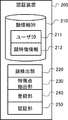
- the authentication device 200 is a device that includes a face information DB (DataBase) 210 and performs face authentication processing.
- the face information DB 210 stores the user ID 211 and the face feature information 212 of the user in association with each other.
- the face feature information 212 of a plurality of users is registered in the authentication device 200 in advance.
- these users include a visited user 41 and a visitor 40.
- the face information DB 210 is realized by, for example, a storage device such as a memory included in the authentication device 200.
- the face information DB 210 is also referred to as a storage unit.
- the authentication device 200 collates the face image or face feature information included in the request with the face feature information 212 of each user, and returns the collation result to the requester.
- the entrance terminal 300 is an information processing device installed at the entrance of a predetermined space. In this embodiment, it is installed at the entrance of the floor 42.
- the entrance terminal 300 includes a camera 310 and a display unit 320.
- the camera 310 is an example of a photographing device installed at the entrance, and is installed so as to photograph the face of the visitor 40 who came to the entrance of the floor 42.
- the display unit 320 is a display device, and specifically, is a platform panel display such as a liquid crystal display, a plasma display, or an organic EL (Electro-Luminescence) display. In the present embodiment, the display unit 320 is configured as a touch panel and also functions as an input device that receives input from the user.
- the entrance terminal 300 includes the camera 310 and the display unit 320, but either the camera 310 or the display unit 320, or both of them are used as a device different from the entrance terminal 300. It may exist.
- the terminal device 400 is an information processing device such as a PC (Personal Computer) installed for each seat provided in a predetermined space. In the present embodiment, the terminal device 400 is installed for each seat provided in the floor 42. In FIG. 3, two terminal devices 400 are shown as an example, but the number of terminal devices 400 may be three or more, or one. In the present embodiment, the seat to be used is not determined for each user, and the user can use any terminal device 400.
- the terminal device 400 receives the notification from the visit support device 100 via the network 600 and outputs the notification content.
- the output of the notification content may be a display output or a voice output.
- the terminal device 400 includes a display and displays on the display. Further, in the case of output by voice, the terminal device 400 includes a speaker and outputs voice from the speaker.
- the camera 500 is a camera that shoots in a predetermined space. More specifically, the camera 500 is a camera installed to capture the face of a user in a seat in a predetermined space. The image taken by the camera 500 is transmitted to the visit support device 100. A plurality of cameras 500 may be set.
- FIG. 4 is a block diagram showing the configuration of the authentication device 200.
- the authentication device 200 includes the above-mentioned face information DB 210, a face detection unit 220, a feature point extraction unit 230, a registration unit 240, and an authentication unit 250.
- the face detection unit 220 detects a face area included in an image for registering face information or an image for face recognition.
- the face detection unit 220 detects a face region from the image by a known image recognition process.
- the feature point extraction unit 230 extracts feature points from the face region detected by the face detection unit 220.
- the feature point extraction unit 230 may extract the feature amount for the feature point. Further, instead of these, other feature information may be extracted.
- the feature point extraction unit 230 extracts facial feature information (also referred to as face information) for face recognition. Since face recognition can be realized by a known technique, detailed description of feature information for face recognition will be omitted.
- the registration unit 240 registers the feature information extracted by the feature point extraction unit 230 in the face information DB 210 together with the user ID.
- the registration unit 240 newly issues a user ID when registering the feature information.
- the registration unit 240 registers the issued user ID and the feature information extracted from the image for registering the face information in the face information DB 210 in association with each other.
- the authentication unit 250 performs face authentication by collating the feature information extracted by the feature point extraction unit 230 from the image for face authentication with the feature information registered in the face information DB 210.
- the authentication unit 250 returns to the device that sent the authentication request whether or not the feature information matches. Whether or not the feature information matches depends on the success or failure of the authentication.
- FIG. 5 is a flowchart showing the flow of face information registration processing by the authentication device 200.
- the flow of the face information registration process will be described with reference to FIG.
- the authentication device 200 acquires an image of the user's face.
- the authentication device 200 acquires an image included in the face information registration request received from the face information registration device (not shown) via the network 600.
- the face information registration device may be an information processing device such as a personal computer.
- the face detection unit 220 detects the face region included in the image acquired in step S101.
- step S103 the feature point extraction unit 230 extracts facial feature information from the face region detected in step S102.
- step S104 the registration unit 240 issues a user ID, associates the user ID with facial feature information, and registers the user ID in the face information DB 210.
- the registration unit 240 may acquire personal information such as the name of the user to be registered from the face information registration device or the like, and register this personal information in the face information DB 210 in association with the user ID.
- the registration unit 240 may return the registration result to the device that sends the face information registration request.
- the authentication device 200 may receive a face information registration request including facial feature information. In this case, the processes of steps S101 to S103 can be omitted.
- FIG. 6 is a flowchart showing the flow of face recognition processing by the authentication device 200. Hereinafter, the flow of the face recognition process will be described with reference to FIG.
- the authentication device 200 acquires an image of the user's face.
- the authentication device 200 receives a face recognition request including an image taken by the camera 310 of the entrance terminal 300 from the visit support device 100 via the network 600, and acquires the image included in the face recognition request.
- step S202 the face detection unit 220 detects the face region included in the image acquired in step S201.
- step S203 the feature point extraction unit 230 extracts facial feature information from the face region detected in step S202.
- the authentication device 200 may receive a face authentication request including face feature information. In this case, the processes of steps S201 to S203 can be omitted.
- step S204 the authentication unit 250 collates the feature information to be authenticated with the face information DB 210.
- the feature information to be authenticated matches the feature information of any of the registered users (YES in step S205)
- the process proceeds to step S206. If it does not match the feature information of any user (NO in step S205), the process proceeds to step S208.
- step S206 the authentication unit 250 identifies the user ID of the user whose feature information to be authenticated and the feature information match. Then, in step S207, the authentication unit 250 transmits an authentication result indicating that the face authentication has been successful to the device (for example, the visit support device 100) that is the source of the face authentication request. Specifically, the authentication unit 250 returns to the requester the user ID specified that the face authentication was successful. The authentication unit 250 may return personal information such as the name of the authenticated user to the requester. On the other hand, in step S208, the authentication unit 250 transmits an authentication result indicating that the face authentication has failed to the device (for example, the visit support device 100) that is the source of the face authentication request.
- FIG. 7 is a block diagram showing the configuration of the entrance terminal 300.
- the entrance terminal 300 includes a storage unit 330, a communication unit 340, and a control unit 350 in addition to the camera 310 and the display unit 320 described above.
- the display unit 320 is configured as a touch panel and receives input from the user, but the display unit 320 does not necessarily have to have a function of receiving input from the user. Further, in this case, the entrance terminal 300 may be provided with an input device for receiving input from the user, in addition to the display unit 320.
- the storage unit 330 is a storage device that stores a program for realizing each function of the entrance terminal 300 and data used for processing of the entrance terminal 300.
- This storage device may be, for example, a non-volatile storage device such as a hard disk or a flash memory, or may include a memory such as a RAM (RandomAccessMemory).
- the communication unit 340 is a communication interface for performing communication via the network 600.
- the control unit 350 is a processor, that is, a control device that controls each configuration of the entrance terminal 300. The control unit 350 reads the program into the memory and executes the process. As a result, the control unit 350 realizes the functions of the shooting control unit 351 and the input / output control unit 352.
- the shooting control unit 351 controls the camera 310 to shoot a visitor arriving at the entrance. For example, when a shooting instruction is input from a visitor arriving at the entrance, the shooting control unit 351 shoots an image including the visitor's face. In addition, as this shooting instruction, an instruction to reserve a visit may be used. Further, the photographing control unit 351 transmits the captured image to the visit support device 100 via the communication unit 340 and the network 600.
- the input / output control unit 352 controls the process of receiving input from the user and the process of displaying information on the display unit 320. For example, the input / output control unit 352 performs an input process for designating a visited user from a visitor (for example, an ID or a name of the visited user), an input process for an instruction to reserve a visit, and the like.
- the input / output control unit 352 transmits the received input to the visit support device 100 via the communication unit 340 and the network 600. Further, the input / output control unit 352 displays the information received from the visit support device 100 via the network 600 and the communication unit 340 on the display unit 320. For example, the input / output control unit 352 displays the floor map received from the visit support device 100, the response result to the visit reservation, and the like on the display unit 320.
- the entrance terminal 300 may be communicably connected to a gate that controls the entry and exit of people in the space (floor). In that case, the entrance terminal 300 may unlock the gate when a response permitting the reservation (a response permitting the visit) is obtained from the visit support device 100 as a response to the visit reservation.
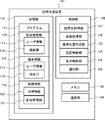
- FIG. 8 is a block diagram showing the configuration of the visit support device 100.
- the visit support device 100 includes a storage unit 110, a memory 130, a communication unit 140, and a control unit 150.
- the storage unit 110 is a non-volatile storage device such as a hard disk or a flash memory.
- the storage unit 110 stores a program 111 for performing various processes of the visit support device 100. Further, the storage unit 110 stores the face image information 112 and the terminal information 115.
- the face image information 112 is a face image for each user. That is, the face image information 112 is information in which the user information 113 including the information for identifying the user and the face image 114 of the user are associated with each other.
- the face image information 112 is used, for example, to display a face image of a user present on the floor on a floor map. Therefore, a face image of a user who may exist on the floor is stored in the storage unit 110 in advance as face image information 112.
- the terminal information 115 is information indicating the terminal device 400 used by each user. That is, the terminal information 115 is information in which the user information 113 including the information for identifying the user and the terminal ID 116 for identifying the terminal device 400 currently used by the user are associated with each other.
- the terminal information 115 is used, for example, to notify a user present on the floor of a visit. Therefore, information for identifying the terminal device 400 used by the user existing on the floor is stored in the storage unit 110 as terminal information. For example, when a user logs in to the terminal device 400, the ID of the terminal device 400 and the user information 113 of the user who logged in to the terminal device 400 are notified to the visit support device 100, and the terminal information 115 is stored based on this notification. NS.
- the memory 130 is a volatile storage device such as a RAM, and is a storage area for temporarily holding information when the control unit 150 operates.
- the communication unit 140 is a communication interface for performing communication via the network 600. For example, the communication unit 140 outputs the data acquired via the network 600 to the control unit 150. Further, the communication unit 140 outputs the data received from the control unit 150 to the network 600.
- the control unit 150 is a processor such as a CPU that controls each configuration of the visit support device 100, that is, a control device.
- the control unit 150 reads the program 111 from the storage unit 110 into the memory 130 and executes the program 111. As a result, the control unit 150 realizes the functions of the visit destination acquisition unit 151, the image acquisition unit 152, the seat position identification unit 153, the authentication control unit 154, the display control unit 155, and the notification unit 156.
- the visited destination acquisition unit 151 corresponds to the visited destination acquisition unit 2 in FIG.
- the visit destination acquisition unit 151 acquires information that identifies a person who the visitor who arrives at the entrance of the floor wants to visit.
- the visited destination acquisition unit 151 acquires the visited destination user by receiving the input for specifying the visited destination user (for example, the ID or name of the visited destination user) input by the visitor to the entrance terminal 300. ..
- the image acquisition unit 152 corresponds to the image acquisition unit 3 in FIG.
- the image acquisition unit 152 acquires an image taken by the visitor by the camera 310 of the entrance terminal 300 via the network 600. Further, the image acquisition unit 152 acquires the captured image of the camera 500 via the network 600.
- one image acquisition unit 152 is shown for convenience of explanation, but the visit support device 100 includes an image acquisition unit that acquires an image of the camera 310 and an image of the camera 500.
- the two image acquisition units of the image acquisition unit for acquiring the above may be provided as a configuration.
- the seat position specifying unit 153 specifies the seat position where the user is seated in a predetermined space (floor). In the present embodiment, the seat position where the user is seated is specified based on the image taken by the camera 500. When the seating position of the user is fixed, that is, when the user is not allowed to freely select a seat, the seat position specifying unit 153 indicates a pre-registered seat position for each user. The seat position of the user may be specified by referring to the management information. In this case, the camera 500 may not be installed. The specific details of the seat position based on the image of the camera 500 will be described later.
- the authentication control unit 154 corresponds to the authentication control unit 4 in FIG. In the present embodiment, the authentication control unit 154 controls to perform the face recognition process using the authentication device 200.
- the authentication control unit 154 controls the image including the visitor's face transmitted from the entrance terminal 300 to perform face authentication. For example, the authentication control unit 154 transmits a face recognition request including an image received from the entrance terminal 300 to the authentication device 200.
- the authentication result is received from the authentication device 200. As a result, the visitor's face recognition is performed.
- the display control unit 155 controls the display unit 320 of the entrance terminal 300 to display a map showing the seat position specified by the seat position identification unit 153 together with information identifying a user who uses the seat. Specifically, in the present embodiment, the display control unit 155 generates a floor map showing the seat position of the user together with the face image 114 of the user stored in the storage unit 110, and the generated floor map is used as an entrance terminal. It is displayed on the display unit 320 of 300. As the information for identifying the user who uses the seat, the user's name or ID may be used instead of the face image 114. As described above, in the present embodiment, since the map showing the seat position of the user together with the information for identifying the user is displayed, the visitor can easily grasp the seat position of the user.
- the floor map can be used not only to show the seat position of the user but also to specify the visited user or to display the route from the entrance to the visited user.
- the display control unit 155 controls the display of the seat position so that only the users who satisfy a predetermined condition among the seated users are displayed. More specifically, the display control unit 155 controls to display only the users who correspond to the visited users among the seated users. By doing so, the visitor can easily grasp the position of the visitor.
- other conditions may be used as a predetermined condition.
- the condition may be that the visitor is relevant.
- the user who is related to the visitor may be, for example, a user who has communicated with the visitor by e-mail in the past, or a user who has attended the same meeting as the visitor.
- the visit support device 100 may store information indicating the relationship between the users in the storage unit 110.
- the display control unit 155 may control to display the seat positions of all the users who are present. Even in such a case, the floor map is used not only to show the seat position of the user but also to specify the visited user or to display the route from the entrance to the visited user. You can also do it.
- the display control unit 155 displays the user interface image for accepting the visit reservation on the display unit 320 of the entrance terminal 300.
- FIG. 9 is a diagram showing an example of a screen displayed on the display unit 320 of the entrance terminal 300 under the control of the display control unit 155.
- a floor map 53 including a map image 50 of the entire floor, a visitor's current location 51, and an image 52 showing the seat position of the visited user, and a user interface image 54 for accepting a visit reservation.
- the current location 51 is a position corresponding to the entrance of the floor.
- the display control unit 155 may further display the route from the current location 51 to the seat position of the visited user.
- the image 52 includes a face image 52a of the visited user and identification information 52b of the visited user. These are specific examples of information that identifies a user who uses a seat.
- a visit reservation request is transmitted to the visit support device 100. That is, when the entrance terminal 300 receives an input from the visitor instructing the reservation of the visit with the visiting user, the entrance terminal 300 transmits the visit reservation request to the visit support device 100.
- the image 52 may also be used as a user interface image for accepting a visit reservation. That is, when the visitor performs an operation of selecting the image 52 displayed at the seat position of the visited user, the visit reservation request may be transmitted to the visit support device 100.
- the notification unit 156 corresponds to the notification unit 5 in FIG.
- the notification unit 156 notifies the terminal device 400 associated with the visiting user that the visitor is planning to visit.
- the notification unit 156 refers to the terminal information 115 and identifies the terminal device 400 used by the visited user.
- the notification unit 156 gives such a notification when the visitor's face recognition is successful. Therefore, it is possible to prevent the visiting user from being bothered by the notification of the visit of the visitor who cannot be authenticated.
- the notification unit 156 may give a notification regardless of the result of face recognition.
- the notification unit 156 notifies the terminal device 400 of the visitor information.
- the notification unit 156 notifies the terminal device 400 of the information about the identified visitor. Specifically, information that identifies the visitor, such as a name, is notified. By doing so, the visited user can know specifically who visited.
- the notification unit 156 gives the above-mentioned notification when a reservation for a visit is requested. Specifically, when the visitor performs an operation of selecting the user interface image 54 for accepting the visit reservation, the notification unit 156 receives the visit reservation request from the entrance terminal 300. Then, upon receiving this reservation request, the notification unit 156 notifies. By doing so, the notification can be given only when the visitor's intention to visit is clear. That is, it is possible to suppress unnecessary notification.
- FIG. 10 is a diagram showing a display example of a notification in the terminal device 400 used by the visited user.
- the display of the terminal device 400 is notified of a visit by a visitor identified by the identification information XX (for example, a name or ID) to a user identified by the identification information YY.
- XX for example, a name or ID
- YY user interface images 55a and 55b for selecting whether or not to allow the requested visit reservation (that is, whether or not to allow the visit) are displayed.
- the notification unit 156 may give various notifications as notifications about the visit. For example, this notification may include the visitor's personal information.
- the personal information may be a face image of the visitor.
- the face image may be an image taken by the entrance terminal 300.
- the personal information may be an attribute of the visitor (for example, affiliated company, affiliated department, or job title).
- the notification may also include historical information about the visitor's visit. Specifically, this historical information may be information indicating the number of visits by the visitor, that is, the total number of visits, or the number of times the visitor has been permitted to visit in the past. It may be the number of times the visitor has been denied a visit in the past.
- the notification may also include information indicating whether or not the visitor falls under a given person. Specifically, this information may be information indicating whether or not it corresponds to an important person preset by the visited user, or whether or not it corresponds to a person requiring attention preset by the visited user. It may be information indicating.
- the visited user specifies whether or not to allow the visitor's visit by inputting an instruction to select one of the user interface images 55a and 55b to the terminal device 400.
- the terminal device 400 transmits this specified content to the visit support device 100 as a response result to the notification.
- This response result may be displayed on the display unit 320 of the entrance terminal 300 as shown in FIG. 11 or FIG.
- FIG. 11 shows a display example when a response permitting the visit is obtained.
- FIG. 12 shows a display example when a response to refuse the visit is obtained. That is, when the display control unit 155 of the visit support device 100 receives the response result for the notification about the visit from the terminal device 400, the display control unit 155 may display the response result on the display unit 320.
- the entrance terminal 300 unlocks the gate that controls the entry and exit of people in the space (floor) when a response permitting the visit is obtained, and when a response denying the visit is obtained, the entrance terminal 300 of the gate
- the lock may remain locked. Note that such lock control may be realized by another device (for example, the visit support device 100).
- FIG. 13 is a flowchart showing the flow of processing for specifying the seat position using the captured image of the camera 500 that captures the floor.
- the flow of processing will be described with reference to FIG.
- the seat position specifying unit 153 specifies the face image of the user whose seat position is specified. Specifically, the seat position specifying unit 153 identifies the face image of the visited user. The seat position specifying unit 153 identifies the face image of the visited user specified by the information acquired by the visited destination acquisition unit 151 by referring to the face image information 112 stored in the storage unit 110.
- step S302 the image acquisition unit 152 acquires a captured image of the camera 500 that captures the floor.
- This captured image shows the faces of each user in a seat on the floor.
- step S303 the seat position specifying unit 153 searches for the face image of the visited user identified in step S301 from the captured images acquired in step S302. In this search, the position where the visited user's face exists in the captured image acquired in step S302 is specified.
- step S304 the seat position specifying unit 153 specifies the seat position of the visited user based on the search result in step S303. Specifically, the seat position specifying unit 153 specifies the seat position of the visited user based on the position of the face image specified in step S303. Since the shooting range of the camera 500 is predetermined, it is possible to specify the position of the visited user on the floor by specifying the position of the visited user in the captured image of the camera 500.
- the seat position specifying unit 153 searches for the user's face image stored in advance from the captured images in the space (floor), and the seat of the user is based on the position where the face image is searched.
- the position may be specified. It should be noted that such identification of the seat position may be performed for a user other than the visited user. That is, it may be performed for any user on the floor. By specifying the seat position in this way, the seat position of the user can be specified even when the seat position is not predetermined.
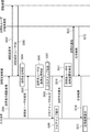
- FIG. 14 is a sequence chart showing an example of the processing flow of the visit support system 10 according to the second embodiment.
- the processing flow will be described with reference to FIG.
- the face information DB 210 of the authentication device 200 stores the user ID 211 and the face feature information 212 for various users in advance. And.
- step S401 When the visitor comes to the entrance of the floor, the visitor inputs to the entrance terminal 300 to specify the visiting user. In step S401, this input information is transmitted from the entrance terminal 300 to the visit support device 100. As a result, the visited destination acquisition unit 151 acquires the visited destination user.
- the seat position specifying unit 153 of the visit support device 100 specifies the seat position where the user is seated on the floor.
- the seat position specifying unit 153 specifies the seat position of the visited user acquired by the visited destination acquisition unit 151.
- step S403 the display control unit 155 generates a floor map showing the seat position of the visited user together with the face image of the visited user. Then, in step S404, the display control unit 155 controls to output the generated floor map to the entrance terminal 300 and display it on the display unit 320 of the entrance terminal 300. At this time, the display control unit 155 also causes the display unit 320 to display the user interface image for accepting the visit reservation. As a result, in step S405, the display unit 320 of the entrance terminal 300 displays the floor map as shown in FIG.
- the visitor makes a visit reservation to meet with the visited user. Specifically, the visitor performs an operation such as touching the user interface image to input a visit reservation instruction to the entrance terminal 300.
- the visit reservation request is transmitted from the entrance terminal 300 to the visit support device 100.
- an image including a visitor's face taken by the camera 310 of the entrance terminal 300 is transmitted from the entrance terminal 300 to the visit support device 100.
- step S408 the authentication control unit 154 of the visit support device 100 transmits a face recognition request including the image obtained in step S407 to the authentication device 200.
- step S409 the visit support device 100 receives the authentication result from the authentication device 200.
- face recognition it is assumed that face recognition is successful. That is, in step S409, the visit support device 100 receives the user ID of the authenticated person from the authentication device 200 together with the authentication result indicating that the face authentication was successful.
- the display control unit 155 may control the display unit 320 of the entrance terminal 300 to display that the authentication has failed. Further, when the face recognition fails, the notification unit 156 does not notify the terminal device 400.
- the notification unit 156 of the visit support device 100 refers to the authentication result obtained in step S409 and identifies the visitor.
- the notification unit 156 may identify the visitor by the user ID, or may identify the visitor by the name associated with the user ID in advance. Further, in step S411, the notification unit 156 identifies the terminal device 400 used by the visited user by referring to the terminal ID 116 of the terminal information 115 stored in the storage unit 110.
- the notification unit 156 notifies the terminal device 400 used by the visited user about the visit.
- the notification unit 156 notifies the terminal device 400 of the occurrence of a visit reservation request together with information for identifying the visitor (for example, a user ID or a name).
- the display as shown in FIG. 10 is performed in the terminal device 400.
- the notification unit 156 gives a notification when the face recognition is successful, but the notification may not be limited to the case where the face recognition is successful. That is, the notification may be given regardless of the result of face recognition.
- the visited user inputs to the terminal device 400 whether or not to allow the visit.
- the response result which is the input content, is transmitted from the terminal device 400 to the visit support device 100.
- this response result is transmitted from the visit support device 100 to the entrance terminal 300.
- the response result is displayed on the entrance terminal 300. Thereby, for example, the display as shown in FIG. 11 or FIG. 12 is performed at the entrance terminal 300.
- the second embodiment has been described above. According to the present embodiment, when the visitor arrives at the entrance of the space and face recognition is performed, the terminal device 400 of the visited user is notified of the visit. Therefore, the visited user can grasp the visit of the visitor. Therefore, the leaving of the visited user is suppressed, and the visitor can meet the visited user more reliably. Therefore, according to the present embodiment, an efficient visit can be realized.
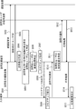
- FIG. 15 is a sequence chart showing an example of the processing flow of the visit support system 10 according to the third embodiment.
- the flow of processing in the present embodiment will be described with reference to FIG.
- step S501 an image including the visitor's face taken by the camera 310 of the entrance terminal 300 is transmitted from the entrance terminal 300 to the visit support device 100.
- step S502 the authentication control unit 154 of the visit support device 100 transmits a face recognition request including the image obtained in step S501 to the authentication device 200. Then, in step S503, the visit support device 100 receives the authentication result from the authentication device 200.
- face recognition it is assumed that face recognition is successful. That is, in step S503, the visit support device 100 receives the user ID of the authenticated person from the authentication device 200 together with the authentication result indicating that the face authentication was successful.
- the display control unit 155 may control the display unit 320 of the entrance terminal 300 to display that the authentication has failed. If the face recognition fails, the floor map is not displayed on the entrance terminal 300. That is, the user's seat position is not displayed.
- step S504 the notification unit 156 of the visit support device 100 refers to the authentication result obtained in step S503 and identifies the visitor.
- step S505 the visitor makes an input for designating the visited user to the entrance terminal 300, and this input information is transmitted from the entrance terminal 300 to the visit support device 100.
- step S506 the seat position specifying unit 153 of the visit support device 100 specifies the seat position where the user is seated on the floor.
- the seat position specifying unit 153 specifies the seat position of the visiting user.
- step S507 the display control unit 155 generates a floor map showing the seat position of the visited user together with the face image of the visited user. Then, in step S508, the display control unit 155 controls to output the generated floor map to the entrance terminal 300 and display it on the display unit 320 of the entrance terminal 300. At this time, the display control unit 155 also causes the display unit 320 to display the user interface image for accepting the visit reservation. As a result, in step S509, the display unit 320 of the entrance terminal 300 displays the floor map as shown in FIG. As described above, in the sequence shown in FIG. 15, when the visitor's face authentication is successful, the display control unit 155 causes the display unit 320 to display the seat position of the user. Therefore, the seat position of the user can be kept secret from the visitor who fails in the authentication.
- step S510 the visit reservation request is transmitted from the entrance terminal 300 to the visit support device 100.
- step S511 the notification unit 156 identifies the terminal device 400 used by the visited user by referring to the terminal ID 116 of the terminal information 115 stored in the storage unit 110.
- step S512 the notification unit 156 notifies the terminal device 400 used by the visited user about the visit.
- the visited user inputs to the terminal device 400 whether or not to allow the visit.
- step S513 the response result, which is the input content, is transmitted from the terminal device 400 to the visit support device 100.
- step S514 the response result is transmitted from the visit support device 100 to the entrance terminal 300.
- step S515 the response result is displayed on the entrance terminal 300.
- the third embodiment has been described above.
- face recognition is performed before the floor map is displayed. Therefore, it is possible to display the floor map only when the face recognition is successful. Therefore, the floor map can be kept secret from visitors who fail in authentication. Further, in the present embodiment, face recognition is performed before the notification. Therefore, even in this embodiment, it is possible not to notify the visit of the visitor who fails in the authentication. Therefore, it is possible to prevent the visiting user from being bothered by the notification of the visit of such a visitor.
- FIG. 16 is a sequence chart showing an example of the processing flow of the visit support system 10 according to the modified example. This modification is different from the sequence chart shown in FIG. 15 in that the floor map is displayed before the visiting user is specified.
- the flow of processing in this modification will be described with reference to FIG.
- the first step of the sequence chart that is, the flow from step S501 to step S504 is the same as the flow shown in FIG. 15, so the description is omitted.
- the display control unit 155 may control the display unit 320 of the entrance terminal 300 to display that the authentication has failed. If the face recognition fails, the floor map is not displayed on the entrance terminal 300. That is, the user's seat position is not displayed.
- step S551 the seat position specifying unit 153 of the visit support device 100 specifies the seat position in which the user is seated on the floor.
- step S552 the display control unit 155 generates a floor map showing the user's seat position on the floor together with the user's face image.
- the display control unit 155 may generate a floor map showing the seat positions of all the users on the floor, or the users on the floor whose seat positions are to be displayed may be the authenticated visitors. It may be changed accordingly.
- the display control unit 155 may display the seat position only for the user who is related to the visitor identified in step S504.
- step S553 the display control unit 155 controls to output the generated floor map to the entrance terminal 300 and display it on the display unit 320 of the entrance terminal 300.
- the floor map is displayed on the display unit 320 of the entrance terminal 300.
- step S555 the visitor inputs an input for designating the visited user to the entrance terminal 300, and this input information is transmitted from the entrance terminal 300 to the visit support device 100.
- the visitor may perform an operation of selecting the user's face image displayed on the floor map (for example, an operation of touching the image) in order to specify the visited user.
- step S555 the process proceeds to step S510 described with reference to FIG. Since the processing after step S510 is the same as the sequence chart of FIG. 15, the description thereof will be omitted.
- the modified example has been explained above.
- face recognition is performed before the floor map is displayed. Therefore, it is possible to display the floor map only when the face recognition is successful.
- the visitor since the floor map is displayed before the visitor specifies the visited user, the visitor can specify the visited user by referring to the floor map.
- FIG. 17 is a block diagram showing the configuration of the visit support device 101 according to the fourth embodiment.
- the visit support device 101 according to the fourth embodiment is different from the visit support device 100 in that it has a storage unit 118 instead of the storage unit 110 and a visit destination acquisition unit 157 instead of the visit destination acquisition unit 151. There is.
- the storage unit 118 stores the conference information 119 in addition to the program 111, the face image information 112, and the terminal information 115.
- the meeting information 119 is information indicating a scheduled meeting, and includes date and time information 120 and participant information 121.
- the date and time information 120 and the participant information 121 are associated with each other for each meeting.
- the date and time information 120 is information indicating the date and time of the meeting.
- the participant information 121 is information for identifying the participating members of the conference. Participant information 121 may be the user ID of a user who participates in the conference.
- the conference information 119 may further include information such as the conference location. As described above, the conference information is information including the date and time of the conference and the definition of the participants of the conference.
- the visit destination acquisition unit 157 identifies the participants who will participate in the conference on the same date and time as the visitor based on the conference information stored in advance, and acquires the specified participants as the visit destination users. As a result, the visited user can be identified without the visitor explicitly specifying the visited user.
- the conference information 119 includes the information of the conference place
- the visit destination acquisition unit 157 identifies the participants of the conference held at the same place on the same date and time, and acquires the specified participants as the visit destination users. May be good.
- the visit destination acquisition unit 157 visits by referring to the stored conference information 119 in which the time difference between the date and time when the conference is held and the date and time when the visitor visits the entrance is within a predetermined range.
- the destination user may be specified.
- the visited destination acquisition unit 157 identifies the visited user by referring to the conference information 119 about the conference held on the same day as the visitor visits the entrance among the stored conference information 119. You may. If a visit occurs at a date and time that is significantly different from the date and time of the meeting, it is assumed that the purpose of the visit is not to meet the participants of the meeting. In other words, it is assumed that they are visiting to meet a person other than the participants in the conference. Therefore, by doing so, it is possible to more reliably identify the visited user while omitting the explicit designation of the visited user by the visitor.
- FIG. 18 is a sequence chart showing an example of the processing flow of the visit support system 10 according to the fourth embodiment.
- the sequence chart shown in FIG. 18 is different from the sequence chart shown in FIG. 15 in that step S505 is replaced with step S601. That is, in step S505, the visiting user is specified based on the input for specifying the visiting user, which is input to the entrance terminal 300 by the visitor.
- step S505 the visiting user is specified based on the input for specifying the visiting user, which is input to the entrance terminal 300 by the visitor.
- the process of step S601 is performed.
- step S601 the visit destination acquisition unit 157 performs a visit destination user identification process using the conference information 119. Specifically, the visit destination acquisition unit 157 identifies the participants who participate in the conference on the same date and time as the visitor specified in step S504 by referring to the conference information. Then, the visit destination acquisition unit 157 sets the specified participant as the visit destination user. In this way, when the visitor acquisition unit 157 succeeds in face recognition of the visitor, the meeting is held on the same date and time as the visitor based on the meeting information stored in advance including the date and time of the meeting and the definition of the participants of the meeting. Identify the participants to participate and acquire the identified participants as visited users. After step S601, the process proceeds to step S506. Since the processes after step S506 are described with reference to FIG. 15, the description will be omitted here.
- the visiting user is specified by using the conference information 119. Therefore, the visited user can be specified without the visitor explicitly specifying the visited user.
- FIG. 19 is a block diagram showing the configuration of the visit support system 11 according to the fifth embodiment.
- each of the terminal devices 400 includes a camera 401 that captures the face of a user who uses the terminal device 400.
- the camera 500 for photographing the floor shown in FIG. 3 may be omitted.
- the visit support system 11 includes a visit support device 102 instead of the visit support device 100. In the present embodiment, it is assumed that the installation position of the terminal device 400 is predetermined in the space.
- FIG. 20 is a block diagram showing the configuration of the visit support device 102 according to the fifth embodiment.
- the visit support device 102 differs from the visit support device 100 in the following points. That is, the visit support device 102 has a storage unit 122 instead of the storage unit 110, an image acquisition unit 158 instead of the image acquisition unit 152, and an authentication control unit 159 instead of the authentication control unit 154. ,
- the seat position specifying unit 160 is provided instead of the seat position specifying unit 153.
- the storage unit 122 is different from the storage unit 110 in that the terminal information 123 is stored instead of the terminal information 115.
- the terminal information 123 is position information indicating the installation position of each terminal device 400.
- the terminal information 123 is information in which the terminal ID 124 that identifies the terminal device 400 and the position information 125 of the terminal device 400 are associated with each other.
- the image acquisition unit 158 acquires the image taken by the visitor by the camera 310 of the entrance terminal 300 and the image taken by the user using the terminal device 400 by the camera 401 of the terminal device 400 via the network 600.
- one image acquisition unit 158 is shown for convenience of explanation, but the visit support device 102 includes an image acquisition unit that acquires an image of the camera 310 and an image of the camera 401.
- the two image acquisition units of the image acquisition unit for acquiring the above may be provided as a configuration.
- the authentication control unit 159 further controls the face authentication of the user who uses the terminal device 400 based on the captured image of the user of the terminal device 400 taken by the camera 401 of the terminal device 400. It is different from the authentication control unit 154. In the block diagram shown in FIG. 20, one authentication control unit 159 is shown for convenience of explanation. However, the visit support device 102 includes two authentication control units, an authentication control unit that controls to perform face recognition of the visitor and an authentication control unit that controls to perform face recognition of the user who uses the terminal device 400. You may prepare.
- the seat position specifying unit 160 determines the user who is identified from the authentication result. It is specified that it is the terminal device 400 to be used. As a result, information corresponding to the terminal information 115 shown in FIG. 8 can be obtained. That is, information in which the user information including the information for identifying the user and the terminal ID for identifying the terminal device 400 used by the user are associated with each other can be obtained. This information is stored in the storage unit 122.
- the seat position specifying unit 160 refers to the terminal information 123 and specifies the installation position of the terminal device 400 used by the user specified from the authentication result.
- the seat position specifying unit 160 uses this installation position as the seat position of the user. In this way, when the face authentication of the user who uses the terminal device 400 is successful, the seat position specifying unit 160 specifies the installation position of the terminal device 400 as the seat position of the user.
- FIG. 21 is a flowchart showing the flow of processing for specifying the seat position using the captured image of the camera 401 of the terminal device 400.
- the processing flow will be described with reference to FIG.
- step S701 the image acquisition unit 158 of the visit support device 102 acquires the captured image of the camera 401 of the terminal device 400 via the network 600. That is, the image acquisition unit 158 acquires an image of the face of the user who uses the terminal device 400.
- step S702 the authentication control unit 159 transmits a face recognition request including the image acquired in step S701 to the authentication device 200. Then, in step S703, the authentication control unit 159 receives the face authentication result from the authentication device 200. If the face recognition is successful (YES in step S704), the process proceeds to step S705. In step S705, the seat position specifying unit 160 specifies the seat position of the user as described above. On the other hand, if the face recognition fails (NO in step S704), the process of specifying the seat position ends.
- the seat position specifying unit 160 specifies the seat position of the user based on the authentication result of the image taken by the camera 401. By specifying the seat position in this way, the seat position of the user can be specified even when the seat position is not predetermined.
- the various embodiments have been described above.
- the processing described in these embodiments may be implemented by a processor and a computer including software (computer program) containing one or more instructions executed by the processor. That is, when the processor reads software (computer program) from the memory and executes it, the processing described in the embodiment can be performed.
- Non-transitory computer-readable media include various types of tangible storage media (tangible storage media).
- Examples of non-temporary computer-readable media include magnetic recording media (eg, flexible disks, magnetic tapes, hard disk drives), magneto-optical recording media (eg, magneto-optical disks), CD-ROMs (Read Only Memory) CD-Rs, CDs. -R / W, including semiconductor memory (for example, mask ROM, PROM (Programmable ROM), EPROM (Erasable PROM), flash ROM, RAM (Random Access Memory)).
- the program may also be supplied to the computer by various types of temporary computer-readable media.
- Examples of temporary computer-readable media include electrical, optical, and electromagnetic waves.
- the temporary computer-readable medium can supply the program to the computer via a wired communication path such as an electric wire and an optical fiber, or a wireless communication path.
- the authentication device 200 is described as a device different from the visit support device 100, 101, or 102, but the authentication device 200 is built in the visit support device 100, 101, or 102. You may be. That is, the function of the authentication device 200 may be included in the visit support device 100, 101, or 102.
- the notification unit 156 notifies the terminal device 400 installed in the seat about the visit, but notifies the terminal device carried by the user such as a smartphone or a tablet terminal. May be good.
- the execution condition of the process is that the face authentication is successful for some processes, but the process may be executed regardless of whether the face authentication is successful or not. ..
- (Appendix 1) A visitor acquisition unit that acquires the visitor user of a visitor who has arrived at the entrance of a predetermined space, An image acquisition unit that acquires a first image taken by the visitor by the image device installed at the entrance, and an image acquisition unit.
- An authentication control unit that controls face recognition of the visitor based on the first captured image, and an authentication control unit.
- a notification unit that notifies the terminal device associated with the visited user about the visit, and a notification unit.
- (Appendix 2) The visit support device according to Appendix 1, wherein the notification unit notifies the terminal device of the visitor's information when the visitor's face authentication is successful.
- (Appendix 3) A seat position specifying unit that specifies the seat position where the user is seated in the space, and A display control unit that displays a map showing the seat position specified by the seat position specifying unit together with information that identifies the user on a display device installed at the entrance.
- (Appendix 4) The visit support device according to Appendix 3, wherein the display control unit controls the display of the seat position so that only the users who satisfy a predetermined condition among the seated users are displayed.
- (Appendix 5) The visit support device according to Appendix 4, wherein the display control unit controls the display of the seat position so that only the user corresponding to the visited user among the seated users is displayed.
- the display control unit further causes the display device to display a user interface image for accepting a visit reservation.
- the visit support device according to any one of Supplementary note 3 to 5, wherein the notification unit gives the notification when a reservation for a visit is requested.
- the visit support device according to any one of Supplementary note 3 to 6, wherein when the display control unit receives a response result to the notification from the terminal device, the display control unit displays the response result on the display device.
- the image acquisition unit further acquires a second captured image, which is a captured image in the space.
- the seat position specifying part is A user's face image stored in advance is searched from the second captured image, and the user's face image is searched.
- the visit support device according to any one of Appendix 3 to 7, which identifies the seat position of the user based on the position where the face image is searched.
- the terminal device has a predetermined installation position in the space.
- the image acquisition unit further acquires a third captured image which is a captured image of the user of the terminal device captured by the camera of the terminal device.
- the authentication control unit further controls to perform face authentication of a user who uses the terminal device based on the third captured image.
- the seat position specifying unit describes the installation position of the terminal device as the seat position of the user when the face authentication of the user using the terminal device is successful. Visit support device.
- the visit support device according to any one of Appendix 1 to 10, wherein the notification includes information indicating whether or not the visitor corresponds to a predetermined person.
- An information processing device installed at the entrance of a predetermined space A visit support device that supports visits to users in the space, and With The visit support device is The visit destination acquisition unit that acquires the visit destination user of the visitor who arrived at the entrance of the space, An image acquisition unit that acquires a first captured image, which is an image captured by the visitor by the camera of the information processing device, and an image acquisition unit.
- An authentication control unit that controls face recognition of the visitor based on the first captured image, and an authentication control unit.
- Visit support system with. The visit support device is A seat position specifying unit that specifies the seat position where the user is seated in the space, and A display control unit that causes the information processing device to display a map showing the seat position specified by the seat position specifying unit together with information that identifies the user.
- (Appendix 16) Get the visited user of the visitor who arrived at the entrance of the predetermined space, A first photographed image, which is an image photographed by the visitor, is acquired by the photographing device installed at the entrance, and the photographed image is acquired.
- a visit support method that notifies the terminal device associated with the visited user about the visit when the face authentication of the visitor is successful.
Landscapes
- Business, Economics & Management (AREA)
- Engineering & Computer Science (AREA)
- Human Resources & Organizations (AREA)
- Physics & Mathematics (AREA)
- General Physics & Mathematics (AREA)
- Entrepreneurship & Innovation (AREA)
- Strategic Management (AREA)
- Theoretical Computer Science (AREA)
- Economics (AREA)
- General Business, Economics & Management (AREA)
- Tourism & Hospitality (AREA)
- Human Computer Interaction (AREA)
- Quality & Reliability (AREA)
- Operations Research (AREA)
- Marketing (AREA)
- Data Mining & Analysis (AREA)
- Health & Medical Sciences (AREA)
- General Health & Medical Sciences (AREA)
- Oral & Maxillofacial Surgery (AREA)
- Multimedia (AREA)
- Development Economics (AREA)
- Educational Administration (AREA)
- Game Theory and Decision Science (AREA)
- Alarm Systems (AREA)
- Collating Specific Patterns (AREA)
Abstract
L'invention concerne un dispositif d'aide à la visite, un système d'aide à la visite, un procédé d'aide à la visite et un programme qui permettent la fourniture d'une assistance pour assurer une visite efficace. Ce dispositif d'aide à la visite (1) comprend : une unité d'acquisition de destination de visite (2) qui acquiert un utilisateur à une destination de visite d'un visiteur arrivant à une entrée dans un espace prescrit ; une unité d'acquisition d'image (3) qui acquiert une première image capturée du visiteur par un dispositif de photographie installé à l'entrée ; une unité de commande d'authentification (4) qui effectue une commande de sorte à provoquer l'exécution d'une authentification de visage sur le visiteur sur la base de la première image capturée ; et une unité de notification (5) qui, dans le cas où l'authentification de visage du visiteur s'avère réussie, donne une notification concernant la visite à un dispositif terminal associé à l'utilisateur au niveau de la destination de visite.
Priority Applications (4)
| Application Number | Priority Date | Filing Date | Title |
|---|---|---|---|
| PCT/JP2020/011750 WO2021186560A1 (fr) | 2020-03-17 | 2020-03-17 | Dispositif d'aide à la visite, système d'aide à la visite, procédé d'aide à la visite et support non transitoire lisible par ordinateur dans lequel est stocké un programme |
| JP2022508664A JPWO2021186560A5 (ja) | 2020-03-17 | 訪問支援装置、訪問支援システム、訪問支援方法及びプログラム | |
| EP20925387.1A EP4123531A4 (fr) | 2020-03-17 | 2020-03-17 | Dispositif d'aide à la visite, système d'aide à la visite, procédé d'aide à la visite et support non transitoire lisible par ordinateur dans lequel est stocké un programme |
| US17/636,451 US20220270425A1 (en) | 2020-03-17 | 2020-03-17 | Visit assistance device, visit assistance system, visit assistance method, and non-transitory computer-readable medium having program stored therein |
Applications Claiming Priority (1)
| Application Number | Priority Date | Filing Date | Title |
|---|---|---|---|
| PCT/JP2020/011750 WO2021186560A1 (fr) | 2020-03-17 | 2020-03-17 | Dispositif d'aide à la visite, système d'aide à la visite, procédé d'aide à la visite et support non transitoire lisible par ordinateur dans lequel est stocké un programme |
Publications (1)
| Publication Number | Publication Date |
|---|---|
| WO2021186560A1 true WO2021186560A1 (fr) | 2021-09-23 |
Family
ID=77770917
Family Applications (1)
| Application Number | Title | Priority Date | Filing Date |
|---|---|---|---|
| PCT/JP2020/011750 WO2021186560A1 (fr) | 2020-03-17 | 2020-03-17 | Dispositif d'aide à la visite, système d'aide à la visite, procédé d'aide à la visite et support non transitoire lisible par ordinateur dans lequel est stocké un programme |
Country Status (3)
| Country | Link |
|---|---|
| US (1) | US20220270425A1 (fr) |
| EP (1) | EP4123531A4 (fr) |
| WO (1) | WO2021186560A1 (fr) |
Citations (5)
| Publication number | Priority date | Publication date | Assignee | Title |
|---|---|---|---|---|
| JP2003208493A (ja) * | 2002-01-11 | 2003-07-25 | Fujitsu Ltd | 企業エントランスにおける自動受付に関する方法 |
| JP2005068899A (ja) * | 2003-08-27 | 2005-03-17 | Yamatake Corp | 入退室管理システムおよび入退室管理方法 |
| JP2012178022A (ja) * | 2011-02-25 | 2012-09-13 | Osaka Gas Co Ltd | 在席確認システム |
| JP2016009234A (ja) * | 2014-06-23 | 2016-01-18 | Lykaon株式会社 | 防犯システム |
| JP2019101566A (ja) | 2017-11-29 | 2019-06-24 | 株式会社 プロネット | 情報処理システム、情報処理方法、情報処理プログラム、および情報処理装置 |
Family Cites Families (4)
| Publication number | Priority date | Publication date | Assignee | Title |
|---|---|---|---|---|
| JP6710562B2 (ja) * | 2016-03-29 | 2020-06-17 | 本田技研工業株式会社 | 受付システム及び受付方法 |
| JP7012266B2 (ja) * | 2018-02-22 | 2022-01-28 | パナソニックIpマネジメント株式会社 | 執務席提示システムおよび執務席提示方法 |
| CN109859370A (zh) * | 2019-04-01 | 2019-06-07 | 苑小军 | 一种智能门铃控制系统及控制方法 |
| CN110415420B (zh) * | 2019-08-22 | 2023-07-14 | 广东鉴面智能科技有限公司 | 一种基于人脸识别的访客智能管理系统及其管理方法 |
-
2020
- 2020-03-17 WO PCT/JP2020/011750 patent/WO2021186560A1/fr unknown
- 2020-03-17 EP EP20925387.1A patent/EP4123531A4/fr active Pending
- 2020-03-17 US US17/636,451 patent/US20220270425A1/en active Pending
Patent Citations (5)
| Publication number | Priority date | Publication date | Assignee | Title |
|---|---|---|---|---|
| JP2003208493A (ja) * | 2002-01-11 | 2003-07-25 | Fujitsu Ltd | 企業エントランスにおける自動受付に関する方法 |
| JP2005068899A (ja) * | 2003-08-27 | 2005-03-17 | Yamatake Corp | 入退室管理システムおよび入退室管理方法 |
| JP2012178022A (ja) * | 2011-02-25 | 2012-09-13 | Osaka Gas Co Ltd | 在席確認システム |
| JP2016009234A (ja) * | 2014-06-23 | 2016-01-18 | Lykaon株式会社 | 防犯システム |
| JP2019101566A (ja) | 2017-11-29 | 2019-06-24 | 株式会社 プロネット | 情報処理システム、情報処理方法、情報処理プログラム、および情報処理装置 |
Non-Patent Citations (1)
| Title |
|---|
| See also references of EP4123531A4 |
Also Published As
| Publication number | Publication date |
|---|---|
| JPWO2021186560A1 (fr) | 2021-09-23 |
| EP4123531A1 (fr) | 2023-01-25 |
| EP4123531A4 (fr) | 2023-05-03 |
| US20220270425A1 (en) | 2022-08-25 |
Similar Documents
| Publication | Publication Date | Title |
|---|---|---|
| JP5979415B2 (ja) | 監視システムおよび電話システム | |
| AU2015297230B2 (en) | Method of modifying image including photographing restricted element, and device and system for performing the method | |
| US10853901B2 (en) | System and method for visitation management in a controlled environment | |
| KR20120078701A (ko) | 안면 인식 훈련용 데이터의 공유 방법 | |
| JP7468038B2 (ja) | 施設予約システム、電子データ提供方法、情報処理端末、情報処理方法、情報処理装置、データ送信方法、プログラム | |
| JP2024056872A (ja) | 滞在管理装置、滞在管理方法、及びプログラム | |
| US20240070566A1 (en) | Visit assistance device, visit assistance system, visit assistance method, and non-transitory computer-readable medium having program stored therein | |
| US20130332531A1 (en) | Information processing device and meeting system | |
| JP2015173307A (ja) | 携帯端末装置、情報処理システム、携帯端末装置の情報処理方法、およびプログラム | |
| WO2021186560A1 (fr) | Dispositif d'aide à la visite, système d'aide à la visite, procédé d'aide à la visite et support non transitoire lisible par ordinateur dans lequel est stocké un programme | |
| JP2010118011A (ja) | 訪問応対支援システム、訪問応対支援方法 | |
| JP7369244B2 (ja) | 情報処理装置及び情報処理方法 | |
| JP2014192804A (ja) | ネットワークカメラ管理装置、ネットワークカメラ管理方法及びネットワークカメラ管理プログラム | |
| JP2018055242A (ja) | 支援装置、支援方法及びプログラム | |
| WO2021191986A1 (fr) | Dispositif d'aide à la visite, procédé d'aide à la visite et programme stockant un support lisible par ordinateur non transitoire | |
| CN114169554A (zh) | 一种会议室的控制方法和装置 | |
| WO2021199186A1 (fr) | Dispositif d'aide à la réservation de conférence, système, procédé et support non transitoire lisible par ordinateur stockant un programme | |
| WO2021192155A1 (fr) | Dispositif de guidage, système de guidage, procédé de guidage et support non temporaire lisible par ordinateur stockant un programme | |
| WO2021071408A1 (fr) | Procédé destiné à former une connexion de réseau | |
| JP6810252B2 (ja) | 情報処理端末および自動応答方法 | |
| JP7420215B2 (ja) | 撮影制御装置、システム、方法及びプログラム | |
| JP7323013B2 (ja) | 情報表示システム、画面生成方法、及びプログラム | |
| WO2022113589A1 (fr) | Serveur, dispositif terminal, programme de traitement d'informations, système de gestion et procédé de gestion | |
| WO2023181094A1 (fr) | Dispositif, système et procédé d'aide à la conférence, et support lisible par ordinateur | |
| JP2023014522A (ja) | 情報表示システム及び情報表示方法 |
Legal Events
| Date | Code | Title | Description |
|---|---|---|---|
| 121 | Ep: the epo has been informed by wipo that ep was designated in this application |
Ref document number: 20925387 Country of ref document: EP Kind code of ref document: A1 |
|
| ENP | Entry into the national phase |
Ref document number: 2022508664 Country of ref document: JP Kind code of ref document: A |
|
| NENP | Non-entry into the national phase |
Ref country code: DE |
|
| ENP | Entry into the national phase |
Ref document number: 2020925387 Country of ref document: EP Effective date: 20221017 |