WO2021186560A1 - Visit assistance device, visit assistance system, visit assistance method, and non-transitory computer-readable medium having program stored therein - Google Patents
Visit assistance device, visit assistance system, visit assistance method, and non-transitory computer-readable medium having program stored therein Download PDFInfo
- Publication number
- WO2021186560A1 WO2021186560A1 PCT/JP2020/011750 JP2020011750W WO2021186560A1 WO 2021186560 A1 WO2021186560 A1 WO 2021186560A1 JP 2020011750 W JP2020011750 W JP 2020011750W WO 2021186560 A1 WO2021186560 A1 WO 2021186560A1
- Authority
- WO
- WIPO (PCT)
- Prior art keywords
- visit
- user
- visitor
- image
- unit
- Prior art date
Links
Images


Classifications
-
- G—PHYSICS
- G06—COMPUTING; CALCULATING OR COUNTING
- G06Q—INFORMATION AND COMMUNICATION TECHNOLOGY [ICT] SPECIALLY ADAPTED FOR ADMINISTRATIVE, COMMERCIAL, FINANCIAL, MANAGERIAL OR SUPERVISORY PURPOSES; SYSTEMS OR METHODS SPECIALLY ADAPTED FOR ADMINISTRATIVE, COMMERCIAL, FINANCIAL, MANAGERIAL OR SUPERVISORY PURPOSES, NOT OTHERWISE PROVIDED FOR
- G06Q10/00—Administration; Management
- G06Q10/10—Office automation; Time management
- G06Q10/109—Time management, e.g. calendars, reminders, meetings or time accounting
- G06Q10/1093—Calendar-based scheduling for persons or groups
- G06Q10/1095—Meeting or appointment
-
- G—PHYSICS
- G06—COMPUTING; CALCULATING OR COUNTING
- G06Q—INFORMATION AND COMMUNICATION TECHNOLOGY [ICT] SPECIALLY ADAPTED FOR ADMINISTRATIVE, COMMERCIAL, FINANCIAL, MANAGERIAL OR SUPERVISORY PURPOSES; SYSTEMS OR METHODS SPECIALLY ADAPTED FOR ADMINISTRATIVE, COMMERCIAL, FINANCIAL, MANAGERIAL OR SUPERVISORY PURPOSES, NOT OTHERWISE PROVIDED FOR
- G06Q10/00—Administration; Management
- G06Q10/06—Resources, workflows, human or project management; Enterprise or organisation planning; Enterprise or organisation modelling
- G06Q10/063—Operations research, analysis or management
- G06Q10/0631—Resource planning, allocation, distributing or scheduling for enterprises or organisations
- G06Q10/06311—Scheduling, planning or task assignment for a person or group
-
- G—PHYSICS
- G06—COMPUTING; CALCULATING OR COUNTING
- G06Q—INFORMATION AND COMMUNICATION TECHNOLOGY [ICT] SPECIALLY ADAPTED FOR ADMINISTRATIVE, COMMERCIAL, FINANCIAL, MANAGERIAL OR SUPERVISORY PURPOSES; SYSTEMS OR METHODS SPECIALLY ADAPTED FOR ADMINISTRATIVE, COMMERCIAL, FINANCIAL, MANAGERIAL OR SUPERVISORY PURPOSES, NOT OTHERWISE PROVIDED FOR
- G06Q10/00—Administration; Management
- G06Q10/10—Office automation; Time management
-
- G—PHYSICS
- G06—COMPUTING; CALCULATING OR COUNTING
- G06Q—INFORMATION AND COMMUNICATION TECHNOLOGY [ICT] SPECIALLY ADAPTED FOR ADMINISTRATIVE, COMMERCIAL, FINANCIAL, MANAGERIAL OR SUPERVISORY PURPOSES; SYSTEMS OR METHODS SPECIALLY ADAPTED FOR ADMINISTRATIVE, COMMERCIAL, FINANCIAL, MANAGERIAL OR SUPERVISORY PURPOSES, NOT OTHERWISE PROVIDED FOR
- G06Q90/00—Systems or methods specially adapted for administrative, commercial, financial, managerial or supervisory purposes, not involving significant data processing
- G06Q90/20—Destination assistance within a business structure or complex
-
- G—PHYSICS
- G07—CHECKING-DEVICES
- G07C—TIME OR ATTENDANCE REGISTERS; REGISTERING OR INDICATING THE WORKING OF MACHINES; GENERATING RANDOM NUMBERS; VOTING OR LOTTERY APPARATUS; ARRANGEMENTS, SYSTEMS OR APPARATUS FOR CHECKING NOT PROVIDED FOR ELSEWHERE
- G07C9/00—Individual registration on entry or exit
- G07C9/30—Individual registration on entry or exit not involving the use of a pass
- G07C9/32—Individual registration on entry or exit not involving the use of a pass in combination with an identity check
- G07C9/37—Individual registration on entry or exit not involving the use of a pass in combination with an identity check using biometric data, e.g. fingerprints, iris scans or voice recognition
-
- G—PHYSICS
- G06—COMPUTING; CALCULATING OR COUNTING
- G06V—IMAGE OR VIDEO RECOGNITION OR UNDERSTANDING
- G06V40/00—Recognition of biometric, human-related or animal-related patterns in image or video data
- G06V40/10—Human or animal bodies, e.g. vehicle occupants or pedestrians; Body parts, e.g. hands
- G06V40/16—Human faces, e.g. facial parts, sketches or expressions
- G06V40/172—Classification, e.g. identification
-
- G—PHYSICS
- G07—CHECKING-DEVICES
- G07C—TIME OR ATTENDANCE REGISTERS; REGISTERING OR INDICATING THE WORKING OF MACHINES; GENERATING RANDOM NUMBERS; VOTING OR LOTTERY APPARATUS; ARRANGEMENTS, SYSTEMS OR APPARATUS FOR CHECKING NOT PROVIDED FOR ELSEWHERE
- G07C2209/00—Indexing scheme relating to groups G07C9/00 - G07C9/38
- G07C2209/04—Access control involving a hierarchy in access rights
-
- G—PHYSICS
- G07—CHECKING-DEVICES
- G07C—TIME OR ATTENDANCE REGISTERS; REGISTERING OR INDICATING THE WORKING OF MACHINES; GENERATING RANDOM NUMBERS; VOTING OR LOTTERY APPARATUS; ARRANGEMENTS, SYSTEMS OR APPARATUS FOR CHECKING NOT PROVIDED FOR ELSEWHERE
- G07C9/00—Individual registration on entry or exit
- G07C9/30—Individual registration on entry or exit not involving the use of a pass
- G07C9/38—Individual registration on entry or exit not involving the use of a pass with central registration
Definitions
- This disclosure relates to a non-temporary computer-readable medium in which a visit support device, a visit support system, a visit support method, and a program are stored.
- Patent Document 1 discloses a system in which a user's seating status can be confirmed without moving to the seat position.
- the face of the user is detected based on the input image from the camera of the user terminal, and it is determined whether or not the user is present. Then, the presence information, which is the determination result, is stored in the server.
- Patent Document 1 it is possible to confirm the presence status of the visited user in advance. However, even if the visitor goes to the seat of the visited user after confirming the presence status of the visited user in advance at the entrance of the floor where the visited user is located, the visitor will be seated. There is a possibility that the user at the visited destination will leave the seat on the way. In this case, the visitor cannot meet the visited user. That is, efficient visits cannot be realized.
- This disclosure is made to solve such problems, and provides visit support devices, visit support systems, visit support methods, and programs that can support the realization of efficient visits. The purpose.
- the visit support device is A visitor acquisition unit that acquires the visitor user of a visitor who has arrived at the entrance of a predetermined space, An image acquisition unit that acquires a first image taken by the visitor by the image device installed at the entrance, and an image acquisition unit. An authentication control unit that controls face recognition of the visitor based on the first captured image, and an authentication control unit. When the visitor's face authentication is successful, a notification unit that notifies the terminal device associated with the visited user about the visit, and a notification unit. Have.
- the visit support system is An information processing device installed at the entrance of a predetermined space, A visit support device that supports visits to users in the space, and With The visit support device is The visit destination acquisition unit that acquires the visit destination user of the visitor who arrived at the entrance of the space, An image acquisition unit that acquires a first captured image, which is an image captured by the visitor by the camera of the information processing device, and an image acquisition unit. An authentication control unit that controls face recognition of the visitor based on the first captured image, and an authentication control unit. When the visitor's face authentication is successful, a notification unit that notifies the terminal device associated with the visited user about the visit, and a notification unit. Have.
- a first photographed image which is an image photographed by the visitor, is acquired by the photographing device installed at the entrance, and the photographed image is acquired. Controlled to perform face recognition of the visitor based on the first captured image, When the face authentication of the visitor is successful, the terminal device associated with the visited user is notified of the visit.
- the program according to the fourth aspect of the present disclosure is A visit destination acquisition step to acquire a visitor destination user of a visitor who has arrived at the entrance of a predetermined space, and An image acquisition step of acquiring a first captured image which is an image captured by the visitor by the imaging device installed at the entrance, and an image acquisition step.
- An authentication control step for controlling the visitor's face recognition based on the first captured image, and When the face authentication of the visitor is successful, a notification step of notifying the terminal device associated with the visited user about the visit, and a notification step. Let the computer run.
- a visit support device it is possible to provide a visit support device, a visit support system, a visit support method, and a program that can support the realization of an efficient visit.
- FIG. It is a block diagram which shows an example of the structure of the visit support apparatus which concerns on Embodiment 1.
- FIG. It is a flowchart which shows the flow of the visit support method which concerns on Embodiment 1.
- FIG. It is a flowchart which shows the flow of the face information registration process by the authentication apparatus which concerns on Embodiment 2.
- FIG. It is a block diagram which shows the structure of the visit support apparatus which concerns on Embodiment 2.
- FIG. It is a figure which shows an example of the screen which is displayed on the display part of an entrance terminal by the control of a display control part.
- a display example is shown when a response permitting the visit is obtained.
- a display example is shown when a response to refuse a visit is obtained.
- It is a flowchart which shows the flow of the process of specifying a seat position using the image taken by the camera which takes a picture of a floor.
- It is a sequence chart which shows an example of the processing flow of the visit support system which concerns on Embodiment 2.
- FIG. 1 is a block diagram showing an example of the configuration of the visit support device 1 according to the first embodiment.
- the visit support device 1 is a device that supports a visit to a user in a predetermined space.
- the space may be a space having a predetermined area, and may be, for example, the entire floor in the building or a room.
- Each seat is provided with, for example, a desk, and the user uses the seat, for example, to perform business.
- the seats to be used may be determined for each user, and the seats to be used may not be determined for each user. That is, the user may be able to select a favorite seat.
- the visit support device 1 includes a visit destination acquisition unit 2, an image acquisition unit 3, an authentication control unit 4, and a notification unit 5.
- the visit destination acquisition unit 2 acquires the visit destination user of the visitor who has arrived at the entrance of the predetermined space.
- a visitor is a person who visits to meet a specific user.
- the visited user is the user of the visited party. That is, the visited user is a person whom the visitor wants to meet.
- the number of visiting users may be multiple.
- the visited destination acquisition unit 2 can acquire the visited destination user by any method.
- the visit destination acquisition unit 2 may acquire the information for designating the visit destination user input to the device at the entrance by the visitor, or may acquire the information for specifying the visit destination user registered in the system in advance. It may be obtained, or it may be obtained by another method.
- the image acquisition unit 3 acquires the photographed image of the visitor by the photographing device installed at the entrance. This imaging device captures an image including the face of a visitor who has arrived at the entrance of a predetermined space.
- the authentication control unit 4 controls to perform face authentication of the visitor based on the captured image acquired by the image acquisition unit 3. This face recognition is performed using, for example, an authentication server, but may be performed by an authentication processing function built in the visit support device 1.
- the notification unit 5 When the visitor's face authentication is successful, the notification unit 5 notifies the terminal device associated with the visited user about the visit. For example, the notification unit 5 may give a notification indicating that the visitor is likely to visit the seat of the visited user, or may notify that the visitor is at the entrance. In addition, the notification unit 5 may further notify the visitor information (for example, ID or name) identified by face recognition. By notifying the visitor's information, the visited user can know the visited person concretely.
- the visitor information for example, ID or name
- FIG. 2 is a flowchart showing the flow of the visit support method according to the first embodiment.
- the visit destination acquisition unit 2 acquires the visit destination user of the visitor who has arrived at the entrance of the predetermined space.
- the image acquisition unit 3 acquires a photographed image of the visitor by the photographing device installed at the entrance.
- the authentication control unit 4 controls to perform face recognition of the visitor based on the captured image acquired by the image acquisition unit 3. If the visitor's face recognition is successful, in step S13, the notification unit 5 notifies the terminal device associated with the visited user about the visit. If the visitor's face recognition fails, the processing of the visit support method is terminated.
- the visit support device 1 when the visitor arrives at the entrance of the space and face recognition is performed, the terminal device of the visited user is notified of the visit. Therefore, the visited user can grasp the visit of the visitor. Therefore, it is possible to prevent the visited user from leaving the seat before the visitor arrives at the seat of the visited user. That is, the visitor can more reliably meet the visited user. Therefore, according to the visit support device 1, an efficient visit can be realized. Further, in particular, by notifying when the face authentication is successful, it is possible not to notify the visit of the visitor who fails in the authentication. Therefore, it is possible to prevent the visiting user from being bothered by the notification of the visit of such a visitor.
- the visit support device 1 includes a processor, a memory, and a storage device as a configuration (not shown). Further, the storage device stores a computer program in which the processing of the visit support method is implemented. Then, the processor reads the computer program from the storage device into the memory and executes the computer program. As a result, the processor realizes the functions of the visit destination acquisition unit 2, the image acquisition unit 3, the authentication control unit 4, and the notification unit 5.
- the visited destination acquisition unit 2, the image acquisition unit 3, the authentication control unit 4, and the notification unit 5 may each be realized by dedicated hardware.
- a part or all of each component of each device may be realized by a general-purpose or dedicated circuitry, a processor, or a combination thereof. These may be composed of a single chip or may be composed of a plurality of chips connected via a bus. A part or all of each component of each device may be realized by a combination of the above-mentioned circuit or the like and a program.
- a processor a CPU (Central Processing Unit), a GPU (Graphics Processing Unit), an FPGA (field-programmable gate array), or the like can be used.
- each component of the visit support device 1 when a part or all of each component of the visit support device 1 is realized by a plurality of information processing devices and circuits, the plurality of information processing devices and circuits may be centrally arranged. It may be distributed.
- the information processing device, the circuit, and the like may be realized as a form in which each of the client-server system, the cloud computing system, and the like is connected via a communication network.
- the function of the visit support device 1 may be provided in the SaaS (Software as a Service) format.
- FIG. 3 is a block diagram showing a configuration of the visit support system 10 according to the second embodiment.
- the visit support system 10 includes a visit support device 100, an authentication device 200, an entrance terminal 300, a terminal device 400, and a camera 500.
- Each of the visit support device 100, the authentication device 200, the entrance terminal 300, the terminal device 400, and the camera 500 is communicably connected via a wired or wireless network 600.
- the visit support device 100 corresponds to the visit support device 1 shown in FIG. 1 and is a device that supports a visit to a user in a predetermined space. That is, the visit support device 1 is a device that supports the visitor 40 to visit the visited user 41 in the space. In this embodiment, as an example, it is assumed that the predetermined space is the floor 42 in the building.
- the visit support device 100 generates a floor map, notifies the visit, and the like.
- the visit support device 100 is, for example, a server device realized by a computer. Details of the visit support device 100 will be described later.
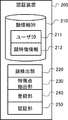
- the authentication device 200 is a device that includes a face information DB (DataBase) 210 and performs face authentication processing.
- the face information DB 210 stores the user ID 211 and the face feature information 212 of the user in association with each other.
- the face feature information 212 of a plurality of users is registered in the authentication device 200 in advance.
- these users include a visited user 41 and a visitor 40.
- the face information DB 210 is realized by, for example, a storage device such as a memory included in the authentication device 200.
- the face information DB 210 is also referred to as a storage unit.
- the authentication device 200 collates the face image or face feature information included in the request with the face feature information 212 of each user, and returns the collation result to the requester.
- the entrance terminal 300 is an information processing device installed at the entrance of a predetermined space. In this embodiment, it is installed at the entrance of the floor 42.
- the entrance terminal 300 includes a camera 310 and a display unit 320.
- the camera 310 is an example of a photographing device installed at the entrance, and is installed so as to photograph the face of the visitor 40 who came to the entrance of the floor 42.
- the display unit 320 is a display device, and specifically, is a platform panel display such as a liquid crystal display, a plasma display, or an organic EL (Electro-Luminescence) display. In the present embodiment, the display unit 320 is configured as a touch panel and also functions as an input device that receives input from the user.
- the entrance terminal 300 includes the camera 310 and the display unit 320, but either the camera 310 or the display unit 320, or both of them are used as a device different from the entrance terminal 300. It may exist.
- the terminal device 400 is an information processing device such as a PC (Personal Computer) installed for each seat provided in a predetermined space. In the present embodiment, the terminal device 400 is installed for each seat provided in the floor 42. In FIG. 3, two terminal devices 400 are shown as an example, but the number of terminal devices 400 may be three or more, or one. In the present embodiment, the seat to be used is not determined for each user, and the user can use any terminal device 400.
- the terminal device 400 receives the notification from the visit support device 100 via the network 600 and outputs the notification content.
- the output of the notification content may be a display output or a voice output.
- the terminal device 400 includes a display and displays on the display. Further, in the case of output by voice, the terminal device 400 includes a speaker and outputs voice from the speaker.
- the camera 500 is a camera that shoots in a predetermined space. More specifically, the camera 500 is a camera installed to capture the face of a user in a seat in a predetermined space. The image taken by the camera 500 is transmitted to the visit support device 100. A plurality of cameras 500 may be set.
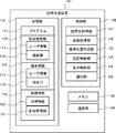
- FIG. 4 is a block diagram showing the configuration of the authentication device 200.
- the authentication device 200 includes the above-mentioned face information DB 210, a face detection unit 220, a feature point extraction unit 230, a registration unit 240, and an authentication unit 250.
- the face detection unit 220 detects a face area included in an image for registering face information or an image for face recognition.
- the face detection unit 220 detects a face region from the image by a known image recognition process.
- the feature point extraction unit 230 extracts feature points from the face region detected by the face detection unit 220.
- the feature point extraction unit 230 may extract the feature amount for the feature point. Further, instead of these, other feature information may be extracted.
- the feature point extraction unit 230 extracts facial feature information (also referred to as face information) for face recognition. Since face recognition can be realized by a known technique, detailed description of feature information for face recognition will be omitted.
- the registration unit 240 registers the feature information extracted by the feature point extraction unit 230 in the face information DB 210 together with the user ID.
- the registration unit 240 newly issues a user ID when registering the feature information.
- the registration unit 240 registers the issued user ID and the feature information extracted from the image for registering the face information in the face information DB 210 in association with each other.
- the authentication unit 250 performs face authentication by collating the feature information extracted by the feature point extraction unit 230 from the image for face authentication with the feature information registered in the face information DB 210.
- the authentication unit 250 returns to the device that sent the authentication request whether or not the feature information matches. Whether or not the feature information matches depends on the success or failure of the authentication.
- FIG. 5 is a flowchart showing the flow of face information registration processing by the authentication device 200.
- the flow of the face information registration process will be described with reference to FIG.
- the authentication device 200 acquires an image of the user's face.
- the authentication device 200 acquires an image included in the face information registration request received from the face information registration device (not shown) via the network 600.
- the face information registration device may be an information processing device such as a personal computer.
- the face detection unit 220 detects the face region included in the image acquired in step S101.
- step S103 the feature point extraction unit 230 extracts facial feature information from the face region detected in step S102.
- step S104 the registration unit 240 issues a user ID, associates the user ID with facial feature information, and registers the user ID in the face information DB 210.
- the registration unit 240 may acquire personal information such as the name of the user to be registered from the face information registration device or the like, and register this personal information in the face information DB 210 in association with the user ID.
- the registration unit 240 may return the registration result to the device that sends the face information registration request.
- the authentication device 200 may receive a face information registration request including facial feature information. In this case, the processes of steps S101 to S103 can be omitted.
- FIG. 6 is a flowchart showing the flow of face recognition processing by the authentication device 200. Hereinafter, the flow of the face recognition process will be described with reference to FIG.
- the authentication device 200 acquires an image of the user's face.
- the authentication device 200 receives a face recognition request including an image taken by the camera 310 of the entrance terminal 300 from the visit support device 100 via the network 600, and acquires the image included in the face recognition request.
- step S202 the face detection unit 220 detects the face region included in the image acquired in step S201.
- step S203 the feature point extraction unit 230 extracts facial feature information from the face region detected in step S202.
- the authentication device 200 may receive a face authentication request including face feature information. In this case, the processes of steps S201 to S203 can be omitted.
- step S204 the authentication unit 250 collates the feature information to be authenticated with the face information DB 210.
- the feature information to be authenticated matches the feature information of any of the registered users (YES in step S205)
- the process proceeds to step S206. If it does not match the feature information of any user (NO in step S205), the process proceeds to step S208.
- step S206 the authentication unit 250 identifies the user ID of the user whose feature information to be authenticated and the feature information match. Then, in step S207, the authentication unit 250 transmits an authentication result indicating that the face authentication has been successful to the device (for example, the visit support device 100) that is the source of the face authentication request. Specifically, the authentication unit 250 returns to the requester the user ID specified that the face authentication was successful. The authentication unit 250 may return personal information such as the name of the authenticated user to the requester. On the other hand, in step S208, the authentication unit 250 transmits an authentication result indicating that the face authentication has failed to the device (for example, the visit support device 100) that is the source of the face authentication request.
- FIG. 7 is a block diagram showing the configuration of the entrance terminal 300.
- the entrance terminal 300 includes a storage unit 330, a communication unit 340, and a control unit 350 in addition to the camera 310 and the display unit 320 described above.
- the display unit 320 is configured as a touch panel and receives input from the user, but the display unit 320 does not necessarily have to have a function of receiving input from the user. Further, in this case, the entrance terminal 300 may be provided with an input device for receiving input from the user, in addition to the display unit 320.
- the storage unit 330 is a storage device that stores a program for realizing each function of the entrance terminal 300 and data used for processing of the entrance terminal 300.
- This storage device may be, for example, a non-volatile storage device such as a hard disk or a flash memory, or may include a memory such as a RAM (RandomAccessMemory).
- the communication unit 340 is a communication interface for performing communication via the network 600.
- the control unit 350 is a processor, that is, a control device that controls each configuration of the entrance terminal 300. The control unit 350 reads the program into the memory and executes the process. As a result, the control unit 350 realizes the functions of the shooting control unit 351 and the input / output control unit 352.
- the shooting control unit 351 controls the camera 310 to shoot a visitor arriving at the entrance. For example, when a shooting instruction is input from a visitor arriving at the entrance, the shooting control unit 351 shoots an image including the visitor's face. In addition, as this shooting instruction, an instruction to reserve a visit may be used. Further, the photographing control unit 351 transmits the captured image to the visit support device 100 via the communication unit 340 and the network 600.
- the input / output control unit 352 controls the process of receiving input from the user and the process of displaying information on the display unit 320. For example, the input / output control unit 352 performs an input process for designating a visited user from a visitor (for example, an ID or a name of the visited user), an input process for an instruction to reserve a visit, and the like.
- the input / output control unit 352 transmits the received input to the visit support device 100 via the communication unit 340 and the network 600. Further, the input / output control unit 352 displays the information received from the visit support device 100 via the network 600 and the communication unit 340 on the display unit 320. For example, the input / output control unit 352 displays the floor map received from the visit support device 100, the response result to the visit reservation, and the like on the display unit 320.
- the entrance terminal 300 may be communicably connected to a gate that controls the entry and exit of people in the space (floor). In that case, the entrance terminal 300 may unlock the gate when a response permitting the reservation (a response permitting the visit) is obtained from the visit support device 100 as a response to the visit reservation.
- FIG. 8 is a block diagram showing the configuration of the visit support device 100.
- the visit support device 100 includes a storage unit 110, a memory 130, a communication unit 140, and a control unit 150.
- the storage unit 110 is a non-volatile storage device such as a hard disk or a flash memory.
- the storage unit 110 stores a program 111 for performing various processes of the visit support device 100. Further, the storage unit 110 stores the face image information 112 and the terminal information 115.
- the face image information 112 is a face image for each user. That is, the face image information 112 is information in which the user information 113 including the information for identifying the user and the face image 114 of the user are associated with each other.
- the face image information 112 is used, for example, to display a face image of a user present on the floor on a floor map. Therefore, a face image of a user who may exist on the floor is stored in the storage unit 110 in advance as face image information 112.
- the terminal information 115 is information indicating the terminal device 400 used by each user. That is, the terminal information 115 is information in which the user information 113 including the information for identifying the user and the terminal ID 116 for identifying the terminal device 400 currently used by the user are associated with each other.
- the terminal information 115 is used, for example, to notify a user present on the floor of a visit. Therefore, information for identifying the terminal device 400 used by the user existing on the floor is stored in the storage unit 110 as terminal information. For example, when a user logs in to the terminal device 400, the ID of the terminal device 400 and the user information 113 of the user who logged in to the terminal device 400 are notified to the visit support device 100, and the terminal information 115 is stored based on this notification. NS.
- the memory 130 is a volatile storage device such as a RAM, and is a storage area for temporarily holding information when the control unit 150 operates.
- the communication unit 140 is a communication interface for performing communication via the network 600. For example, the communication unit 140 outputs the data acquired via the network 600 to the control unit 150. Further, the communication unit 140 outputs the data received from the control unit 150 to the network 600.
- the control unit 150 is a processor such as a CPU that controls each configuration of the visit support device 100, that is, a control device.
- the control unit 150 reads the program 111 from the storage unit 110 into the memory 130 and executes the program 111. As a result, the control unit 150 realizes the functions of the visit destination acquisition unit 151, the image acquisition unit 152, the seat position identification unit 153, the authentication control unit 154, the display control unit 155, and the notification unit 156.
- the visited destination acquisition unit 151 corresponds to the visited destination acquisition unit 2 in FIG.
- the visit destination acquisition unit 151 acquires information that identifies a person who the visitor who arrives at the entrance of the floor wants to visit.
- the visited destination acquisition unit 151 acquires the visited destination user by receiving the input for specifying the visited destination user (for example, the ID or name of the visited destination user) input by the visitor to the entrance terminal 300. ..
- the image acquisition unit 152 corresponds to the image acquisition unit 3 in FIG.
- the image acquisition unit 152 acquires an image taken by the visitor by the camera 310 of the entrance terminal 300 via the network 600. Further, the image acquisition unit 152 acquires the captured image of the camera 500 via the network 600.
- one image acquisition unit 152 is shown for convenience of explanation, but the visit support device 100 includes an image acquisition unit that acquires an image of the camera 310 and an image of the camera 500.
- the two image acquisition units of the image acquisition unit for acquiring the above may be provided as a configuration.
- the seat position specifying unit 153 specifies the seat position where the user is seated in a predetermined space (floor). In the present embodiment, the seat position where the user is seated is specified based on the image taken by the camera 500. When the seating position of the user is fixed, that is, when the user is not allowed to freely select a seat, the seat position specifying unit 153 indicates a pre-registered seat position for each user. The seat position of the user may be specified by referring to the management information. In this case, the camera 500 may not be installed. The specific details of the seat position based on the image of the camera 500 will be described later.
- the authentication control unit 154 corresponds to the authentication control unit 4 in FIG. In the present embodiment, the authentication control unit 154 controls to perform the face recognition process using the authentication device 200.
- the authentication control unit 154 controls the image including the visitor's face transmitted from the entrance terminal 300 to perform face authentication. For example, the authentication control unit 154 transmits a face recognition request including an image received from the entrance terminal 300 to the authentication device 200.
- the authentication result is received from the authentication device 200. As a result, the visitor's face recognition is performed.
- the display control unit 155 controls the display unit 320 of the entrance terminal 300 to display a map showing the seat position specified by the seat position identification unit 153 together with information identifying a user who uses the seat. Specifically, in the present embodiment, the display control unit 155 generates a floor map showing the seat position of the user together with the face image 114 of the user stored in the storage unit 110, and the generated floor map is used as an entrance terminal. It is displayed on the display unit 320 of 300. As the information for identifying the user who uses the seat, the user's name or ID may be used instead of the face image 114. As described above, in the present embodiment, since the map showing the seat position of the user together with the information for identifying the user is displayed, the visitor can easily grasp the seat position of the user.
- the floor map can be used not only to show the seat position of the user but also to specify the visited user or to display the route from the entrance to the visited user.
- the display control unit 155 controls the display of the seat position so that only the users who satisfy a predetermined condition among the seated users are displayed. More specifically, the display control unit 155 controls to display only the users who correspond to the visited users among the seated users. By doing so, the visitor can easily grasp the position of the visitor.
- other conditions may be used as a predetermined condition.
- the condition may be that the visitor is relevant.
- the user who is related to the visitor may be, for example, a user who has communicated with the visitor by e-mail in the past, or a user who has attended the same meeting as the visitor.
- the visit support device 100 may store information indicating the relationship between the users in the storage unit 110.
- the display control unit 155 may control to display the seat positions of all the users who are present. Even in such a case, the floor map is used not only to show the seat position of the user but also to specify the visited user or to display the route from the entrance to the visited user. You can also do it.
- the display control unit 155 displays the user interface image for accepting the visit reservation on the display unit 320 of the entrance terminal 300.
- FIG. 9 is a diagram showing an example of a screen displayed on the display unit 320 of the entrance terminal 300 under the control of the display control unit 155.
- a floor map 53 including a map image 50 of the entire floor, a visitor's current location 51, and an image 52 showing the seat position of the visited user, and a user interface image 54 for accepting a visit reservation.
- the current location 51 is a position corresponding to the entrance of the floor.
- the display control unit 155 may further display the route from the current location 51 to the seat position of the visited user.
- the image 52 includes a face image 52a of the visited user and identification information 52b of the visited user. These are specific examples of information that identifies a user who uses a seat.
- a visit reservation request is transmitted to the visit support device 100. That is, when the entrance terminal 300 receives an input from the visitor instructing the reservation of the visit with the visiting user, the entrance terminal 300 transmits the visit reservation request to the visit support device 100.
- the image 52 may also be used as a user interface image for accepting a visit reservation. That is, when the visitor performs an operation of selecting the image 52 displayed at the seat position of the visited user, the visit reservation request may be transmitted to the visit support device 100.
- the notification unit 156 corresponds to the notification unit 5 in FIG.
- the notification unit 156 notifies the terminal device 400 associated with the visiting user that the visitor is planning to visit.
- the notification unit 156 refers to the terminal information 115 and identifies the terminal device 400 used by the visited user.
- the notification unit 156 gives such a notification when the visitor's face recognition is successful. Therefore, it is possible to prevent the visiting user from being bothered by the notification of the visit of the visitor who cannot be authenticated.
- the notification unit 156 may give a notification regardless of the result of face recognition.
- the notification unit 156 notifies the terminal device 400 of the visitor information.
- the notification unit 156 notifies the terminal device 400 of the information about the identified visitor. Specifically, information that identifies the visitor, such as a name, is notified. By doing so, the visited user can know specifically who visited.
- the notification unit 156 gives the above-mentioned notification when a reservation for a visit is requested. Specifically, when the visitor performs an operation of selecting the user interface image 54 for accepting the visit reservation, the notification unit 156 receives the visit reservation request from the entrance terminal 300. Then, upon receiving this reservation request, the notification unit 156 notifies. By doing so, the notification can be given only when the visitor's intention to visit is clear. That is, it is possible to suppress unnecessary notification.
- FIG. 10 is a diagram showing a display example of a notification in the terminal device 400 used by the visited user.
- the display of the terminal device 400 is notified of a visit by a visitor identified by the identification information XX (for example, a name or ID) to a user identified by the identification information YY.
- XX for example, a name or ID
- YY user interface images 55a and 55b for selecting whether or not to allow the requested visit reservation (that is, whether or not to allow the visit) are displayed.
- the notification unit 156 may give various notifications as notifications about the visit. For example, this notification may include the visitor's personal information.
- the personal information may be a face image of the visitor.
- the face image may be an image taken by the entrance terminal 300.
- the personal information may be an attribute of the visitor (for example, affiliated company, affiliated department, or job title).
- the notification may also include historical information about the visitor's visit. Specifically, this historical information may be information indicating the number of visits by the visitor, that is, the total number of visits, or the number of times the visitor has been permitted to visit in the past. It may be the number of times the visitor has been denied a visit in the past.
- the notification may also include information indicating whether or not the visitor falls under a given person. Specifically, this information may be information indicating whether or not it corresponds to an important person preset by the visited user, or whether or not it corresponds to a person requiring attention preset by the visited user. It may be information indicating.
- the visited user specifies whether or not to allow the visitor's visit by inputting an instruction to select one of the user interface images 55a and 55b to the terminal device 400.
- the terminal device 400 transmits this specified content to the visit support device 100 as a response result to the notification.
- This response result may be displayed on the display unit 320 of the entrance terminal 300 as shown in FIG. 11 or FIG.
- FIG. 11 shows a display example when a response permitting the visit is obtained.
- FIG. 12 shows a display example when a response to refuse the visit is obtained. That is, when the display control unit 155 of the visit support device 100 receives the response result for the notification about the visit from the terminal device 400, the display control unit 155 may display the response result on the display unit 320.
- the entrance terminal 300 unlocks the gate that controls the entry and exit of people in the space (floor) when a response permitting the visit is obtained, and when a response denying the visit is obtained, the entrance terminal 300 of the gate
- the lock may remain locked. Note that such lock control may be realized by another device (for example, the visit support device 100).
- FIG. 13 is a flowchart showing the flow of processing for specifying the seat position using the captured image of the camera 500 that captures the floor.
- the flow of processing will be described with reference to FIG.
- the seat position specifying unit 153 specifies the face image of the user whose seat position is specified. Specifically, the seat position specifying unit 153 identifies the face image of the visited user. The seat position specifying unit 153 identifies the face image of the visited user specified by the information acquired by the visited destination acquisition unit 151 by referring to the face image information 112 stored in the storage unit 110.
- step S302 the image acquisition unit 152 acquires a captured image of the camera 500 that captures the floor.
- This captured image shows the faces of each user in a seat on the floor.
- step S303 the seat position specifying unit 153 searches for the face image of the visited user identified in step S301 from the captured images acquired in step S302. In this search, the position where the visited user's face exists in the captured image acquired in step S302 is specified.
- step S304 the seat position specifying unit 153 specifies the seat position of the visited user based on the search result in step S303. Specifically, the seat position specifying unit 153 specifies the seat position of the visited user based on the position of the face image specified in step S303. Since the shooting range of the camera 500 is predetermined, it is possible to specify the position of the visited user on the floor by specifying the position of the visited user in the captured image of the camera 500.
- the seat position specifying unit 153 searches for the user's face image stored in advance from the captured images in the space (floor), and the seat of the user is based on the position where the face image is searched.
- the position may be specified. It should be noted that such identification of the seat position may be performed for a user other than the visited user. That is, it may be performed for any user on the floor. By specifying the seat position in this way, the seat position of the user can be specified even when the seat position is not predetermined.
- FIG. 14 is a sequence chart showing an example of the processing flow of the visit support system 10 according to the second embodiment.
- the processing flow will be described with reference to FIG.
- the face information DB 210 of the authentication device 200 stores the user ID 211 and the face feature information 212 for various users in advance. And.
- step S401 When the visitor comes to the entrance of the floor, the visitor inputs to the entrance terminal 300 to specify the visiting user. In step S401, this input information is transmitted from the entrance terminal 300 to the visit support device 100. As a result, the visited destination acquisition unit 151 acquires the visited destination user.
- the seat position specifying unit 153 of the visit support device 100 specifies the seat position where the user is seated on the floor.
- the seat position specifying unit 153 specifies the seat position of the visited user acquired by the visited destination acquisition unit 151.
- step S403 the display control unit 155 generates a floor map showing the seat position of the visited user together with the face image of the visited user. Then, in step S404, the display control unit 155 controls to output the generated floor map to the entrance terminal 300 and display it on the display unit 320 of the entrance terminal 300. At this time, the display control unit 155 also causes the display unit 320 to display the user interface image for accepting the visit reservation. As a result, in step S405, the display unit 320 of the entrance terminal 300 displays the floor map as shown in FIG.
- the visitor makes a visit reservation to meet with the visited user. Specifically, the visitor performs an operation such as touching the user interface image to input a visit reservation instruction to the entrance terminal 300.
- the visit reservation request is transmitted from the entrance terminal 300 to the visit support device 100.
- an image including a visitor's face taken by the camera 310 of the entrance terminal 300 is transmitted from the entrance terminal 300 to the visit support device 100.
- step S408 the authentication control unit 154 of the visit support device 100 transmits a face recognition request including the image obtained in step S407 to the authentication device 200.
- step S409 the visit support device 100 receives the authentication result from the authentication device 200.
- face recognition it is assumed that face recognition is successful. That is, in step S409, the visit support device 100 receives the user ID of the authenticated person from the authentication device 200 together with the authentication result indicating that the face authentication was successful.
- the display control unit 155 may control the display unit 320 of the entrance terminal 300 to display that the authentication has failed. Further, when the face recognition fails, the notification unit 156 does not notify the terminal device 400.
- the notification unit 156 of the visit support device 100 refers to the authentication result obtained in step S409 and identifies the visitor.
- the notification unit 156 may identify the visitor by the user ID, or may identify the visitor by the name associated with the user ID in advance. Further, in step S411, the notification unit 156 identifies the terminal device 400 used by the visited user by referring to the terminal ID 116 of the terminal information 115 stored in the storage unit 110.
- the notification unit 156 notifies the terminal device 400 used by the visited user about the visit.
- the notification unit 156 notifies the terminal device 400 of the occurrence of a visit reservation request together with information for identifying the visitor (for example, a user ID or a name).
- the display as shown in FIG. 10 is performed in the terminal device 400.
- the notification unit 156 gives a notification when the face recognition is successful, but the notification may not be limited to the case where the face recognition is successful. That is, the notification may be given regardless of the result of face recognition.
- the visited user inputs to the terminal device 400 whether or not to allow the visit.
- the response result which is the input content, is transmitted from the terminal device 400 to the visit support device 100.
- this response result is transmitted from the visit support device 100 to the entrance terminal 300.
- the response result is displayed on the entrance terminal 300. Thereby, for example, the display as shown in FIG. 11 or FIG. 12 is performed at the entrance terminal 300.
- the second embodiment has been described above. According to the present embodiment, when the visitor arrives at the entrance of the space and face recognition is performed, the terminal device 400 of the visited user is notified of the visit. Therefore, the visited user can grasp the visit of the visitor. Therefore, the leaving of the visited user is suppressed, and the visitor can meet the visited user more reliably. Therefore, according to the present embodiment, an efficient visit can be realized.
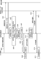
- FIG. 15 is a sequence chart showing an example of the processing flow of the visit support system 10 according to the third embodiment.
- the flow of processing in the present embodiment will be described with reference to FIG.
- step S501 an image including the visitor's face taken by the camera 310 of the entrance terminal 300 is transmitted from the entrance terminal 300 to the visit support device 100.
- step S502 the authentication control unit 154 of the visit support device 100 transmits a face recognition request including the image obtained in step S501 to the authentication device 200. Then, in step S503, the visit support device 100 receives the authentication result from the authentication device 200.
- face recognition it is assumed that face recognition is successful. That is, in step S503, the visit support device 100 receives the user ID of the authenticated person from the authentication device 200 together with the authentication result indicating that the face authentication was successful.
- the display control unit 155 may control the display unit 320 of the entrance terminal 300 to display that the authentication has failed. If the face recognition fails, the floor map is not displayed on the entrance terminal 300. That is, the user's seat position is not displayed.
- step S504 the notification unit 156 of the visit support device 100 refers to the authentication result obtained in step S503 and identifies the visitor.
- step S505 the visitor makes an input for designating the visited user to the entrance terminal 300, and this input information is transmitted from the entrance terminal 300 to the visit support device 100.
- step S506 the seat position specifying unit 153 of the visit support device 100 specifies the seat position where the user is seated on the floor.
- the seat position specifying unit 153 specifies the seat position of the visiting user.
- step S507 the display control unit 155 generates a floor map showing the seat position of the visited user together with the face image of the visited user. Then, in step S508, the display control unit 155 controls to output the generated floor map to the entrance terminal 300 and display it on the display unit 320 of the entrance terminal 300. At this time, the display control unit 155 also causes the display unit 320 to display the user interface image for accepting the visit reservation. As a result, in step S509, the display unit 320 of the entrance terminal 300 displays the floor map as shown in FIG. As described above, in the sequence shown in FIG. 15, when the visitor's face authentication is successful, the display control unit 155 causes the display unit 320 to display the seat position of the user. Therefore, the seat position of the user can be kept secret from the visitor who fails in the authentication.
- step S510 the visit reservation request is transmitted from the entrance terminal 300 to the visit support device 100.
- step S511 the notification unit 156 identifies the terminal device 400 used by the visited user by referring to the terminal ID 116 of the terminal information 115 stored in the storage unit 110.
- step S512 the notification unit 156 notifies the terminal device 400 used by the visited user about the visit.
- the visited user inputs to the terminal device 400 whether or not to allow the visit.
- step S513 the response result, which is the input content, is transmitted from the terminal device 400 to the visit support device 100.
- step S514 the response result is transmitted from the visit support device 100 to the entrance terminal 300.
- step S515 the response result is displayed on the entrance terminal 300.
- the third embodiment has been described above.
- face recognition is performed before the floor map is displayed. Therefore, it is possible to display the floor map only when the face recognition is successful. Therefore, the floor map can be kept secret from visitors who fail in authentication. Further, in the present embodiment, face recognition is performed before the notification. Therefore, even in this embodiment, it is possible not to notify the visit of the visitor who fails in the authentication. Therefore, it is possible to prevent the visiting user from being bothered by the notification of the visit of such a visitor.
- FIG. 16 is a sequence chart showing an example of the processing flow of the visit support system 10 according to the modified example. This modification is different from the sequence chart shown in FIG. 15 in that the floor map is displayed before the visiting user is specified.
- the flow of processing in this modification will be described with reference to FIG.
- the first step of the sequence chart that is, the flow from step S501 to step S504 is the same as the flow shown in FIG. 15, so the description is omitted.
- the display control unit 155 may control the display unit 320 of the entrance terminal 300 to display that the authentication has failed. If the face recognition fails, the floor map is not displayed on the entrance terminal 300. That is, the user's seat position is not displayed.
- step S551 the seat position specifying unit 153 of the visit support device 100 specifies the seat position in which the user is seated on the floor.
- step S552 the display control unit 155 generates a floor map showing the user's seat position on the floor together with the user's face image.
- the display control unit 155 may generate a floor map showing the seat positions of all the users on the floor, or the users on the floor whose seat positions are to be displayed may be the authenticated visitors. It may be changed accordingly.
- the display control unit 155 may display the seat position only for the user who is related to the visitor identified in step S504.
- step S553 the display control unit 155 controls to output the generated floor map to the entrance terminal 300 and display it on the display unit 320 of the entrance terminal 300.
- the floor map is displayed on the display unit 320 of the entrance terminal 300.
- step S555 the visitor inputs an input for designating the visited user to the entrance terminal 300, and this input information is transmitted from the entrance terminal 300 to the visit support device 100.
- the visitor may perform an operation of selecting the user's face image displayed on the floor map (for example, an operation of touching the image) in order to specify the visited user.
- step S555 the process proceeds to step S510 described with reference to FIG. Since the processing after step S510 is the same as the sequence chart of FIG. 15, the description thereof will be omitted.
- the modified example has been explained above.
- face recognition is performed before the floor map is displayed. Therefore, it is possible to display the floor map only when the face recognition is successful.
- the visitor since the floor map is displayed before the visitor specifies the visited user, the visitor can specify the visited user by referring to the floor map.
- FIG. 17 is a block diagram showing the configuration of the visit support device 101 according to the fourth embodiment.
- the visit support device 101 according to the fourth embodiment is different from the visit support device 100 in that it has a storage unit 118 instead of the storage unit 110 and a visit destination acquisition unit 157 instead of the visit destination acquisition unit 151. There is.
- the storage unit 118 stores the conference information 119 in addition to the program 111, the face image information 112, and the terminal information 115.
- the meeting information 119 is information indicating a scheduled meeting, and includes date and time information 120 and participant information 121.
- the date and time information 120 and the participant information 121 are associated with each other for each meeting.
- the date and time information 120 is information indicating the date and time of the meeting.
- the participant information 121 is information for identifying the participating members of the conference. Participant information 121 may be the user ID of a user who participates in the conference.
- the conference information 119 may further include information such as the conference location. As described above, the conference information is information including the date and time of the conference and the definition of the participants of the conference.
- the visit destination acquisition unit 157 identifies the participants who will participate in the conference on the same date and time as the visitor based on the conference information stored in advance, and acquires the specified participants as the visit destination users. As a result, the visited user can be identified without the visitor explicitly specifying the visited user.
- the conference information 119 includes the information of the conference place
- the visit destination acquisition unit 157 identifies the participants of the conference held at the same place on the same date and time, and acquires the specified participants as the visit destination users. May be good.
- the visit destination acquisition unit 157 visits by referring to the stored conference information 119 in which the time difference between the date and time when the conference is held and the date and time when the visitor visits the entrance is within a predetermined range.
- the destination user may be specified.
- the visited destination acquisition unit 157 identifies the visited user by referring to the conference information 119 about the conference held on the same day as the visitor visits the entrance among the stored conference information 119. You may. If a visit occurs at a date and time that is significantly different from the date and time of the meeting, it is assumed that the purpose of the visit is not to meet the participants of the meeting. In other words, it is assumed that they are visiting to meet a person other than the participants in the conference. Therefore, by doing so, it is possible to more reliably identify the visited user while omitting the explicit designation of the visited user by the visitor.
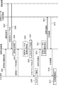
- FIG. 18 is a sequence chart showing an example of the processing flow of the visit support system 10 according to the fourth embodiment.
- the sequence chart shown in FIG. 18 is different from the sequence chart shown in FIG. 15 in that step S505 is replaced with step S601. That is, in step S505, the visiting user is specified based on the input for specifying the visiting user, which is input to the entrance terminal 300 by the visitor.
- step S505 the visiting user is specified based on the input for specifying the visiting user, which is input to the entrance terminal 300 by the visitor.
- the process of step S601 is performed.
- step S601 the visit destination acquisition unit 157 performs a visit destination user identification process using the conference information 119. Specifically, the visit destination acquisition unit 157 identifies the participants who participate in the conference on the same date and time as the visitor specified in step S504 by referring to the conference information. Then, the visit destination acquisition unit 157 sets the specified participant as the visit destination user. In this way, when the visitor acquisition unit 157 succeeds in face recognition of the visitor, the meeting is held on the same date and time as the visitor based on the meeting information stored in advance including the date and time of the meeting and the definition of the participants of the meeting. Identify the participants to participate and acquire the identified participants as visited users. After step S601, the process proceeds to step S506. Since the processes after step S506 are described with reference to FIG. 15, the description will be omitted here.
- the visiting user is specified by using the conference information 119. Therefore, the visited user can be specified without the visitor explicitly specifying the visited user.
- FIG. 19 is a block diagram showing the configuration of the visit support system 11 according to the fifth embodiment.
- each of the terminal devices 400 includes a camera 401 that captures the face of a user who uses the terminal device 400.
- the camera 500 for photographing the floor shown in FIG. 3 may be omitted.
- the visit support system 11 includes a visit support device 102 instead of the visit support device 100. In the present embodiment, it is assumed that the installation position of the terminal device 400 is predetermined in the space.
- FIG. 20 is a block diagram showing the configuration of the visit support device 102 according to the fifth embodiment.
- the visit support device 102 differs from the visit support device 100 in the following points. That is, the visit support device 102 has a storage unit 122 instead of the storage unit 110, an image acquisition unit 158 instead of the image acquisition unit 152, and an authentication control unit 159 instead of the authentication control unit 154. ,
- the seat position specifying unit 160 is provided instead of the seat position specifying unit 153.
- the storage unit 122 is different from the storage unit 110 in that the terminal information 123 is stored instead of the terminal information 115.
- the terminal information 123 is position information indicating the installation position of each terminal device 400.
- the terminal information 123 is information in which the terminal ID 124 that identifies the terminal device 400 and the position information 125 of the terminal device 400 are associated with each other.
- the image acquisition unit 158 acquires the image taken by the visitor by the camera 310 of the entrance terminal 300 and the image taken by the user using the terminal device 400 by the camera 401 of the terminal device 400 via the network 600.
- one image acquisition unit 158 is shown for convenience of explanation, but the visit support device 102 includes an image acquisition unit that acquires an image of the camera 310 and an image of the camera 401.
- the two image acquisition units of the image acquisition unit for acquiring the above may be provided as a configuration.
- the authentication control unit 159 further controls the face authentication of the user who uses the terminal device 400 based on the captured image of the user of the terminal device 400 taken by the camera 401 of the terminal device 400. It is different from the authentication control unit 154. In the block diagram shown in FIG. 20, one authentication control unit 159 is shown for convenience of explanation. However, the visit support device 102 includes two authentication control units, an authentication control unit that controls to perform face recognition of the visitor and an authentication control unit that controls to perform face recognition of the user who uses the terminal device 400. You may prepare.
- the seat position specifying unit 160 determines the user who is identified from the authentication result. It is specified that it is the terminal device 400 to be used. As a result, information corresponding to the terminal information 115 shown in FIG. 8 can be obtained. That is, information in which the user information including the information for identifying the user and the terminal ID for identifying the terminal device 400 used by the user are associated with each other can be obtained. This information is stored in the storage unit 122.
- the seat position specifying unit 160 refers to the terminal information 123 and specifies the installation position of the terminal device 400 used by the user specified from the authentication result.
- the seat position specifying unit 160 uses this installation position as the seat position of the user. In this way, when the face authentication of the user who uses the terminal device 400 is successful, the seat position specifying unit 160 specifies the installation position of the terminal device 400 as the seat position of the user.
- FIG. 21 is a flowchart showing the flow of processing for specifying the seat position using the captured image of the camera 401 of the terminal device 400.
- the processing flow will be described with reference to FIG.
- step S701 the image acquisition unit 158 of the visit support device 102 acquires the captured image of the camera 401 of the terminal device 400 via the network 600. That is, the image acquisition unit 158 acquires an image of the face of the user who uses the terminal device 400.
- step S702 the authentication control unit 159 transmits a face recognition request including the image acquired in step S701 to the authentication device 200. Then, in step S703, the authentication control unit 159 receives the face authentication result from the authentication device 200. If the face recognition is successful (YES in step S704), the process proceeds to step S705. In step S705, the seat position specifying unit 160 specifies the seat position of the user as described above. On the other hand, if the face recognition fails (NO in step S704), the process of specifying the seat position ends.
- the seat position specifying unit 160 specifies the seat position of the user based on the authentication result of the image taken by the camera 401. By specifying the seat position in this way, the seat position of the user can be specified even when the seat position is not predetermined.
- the various embodiments have been described above.
- the processing described in these embodiments may be implemented by a processor and a computer including software (computer program) containing one or more instructions executed by the processor. That is, when the processor reads software (computer program) from the memory and executes it, the processing described in the embodiment can be performed.
- Non-transitory computer-readable media include various types of tangible storage media (tangible storage media).
- Examples of non-temporary computer-readable media include magnetic recording media (eg, flexible disks, magnetic tapes, hard disk drives), magneto-optical recording media (eg, magneto-optical disks), CD-ROMs (Read Only Memory) CD-Rs, CDs. -R / W, including semiconductor memory (for example, mask ROM, PROM (Programmable ROM), EPROM (Erasable PROM), flash ROM, RAM (Random Access Memory)).
- the program may also be supplied to the computer by various types of temporary computer-readable media.
- Examples of temporary computer-readable media include electrical, optical, and electromagnetic waves.
- the temporary computer-readable medium can supply the program to the computer via a wired communication path such as an electric wire and an optical fiber, or a wireless communication path.
- the authentication device 200 is described as a device different from the visit support device 100, 101, or 102, but the authentication device 200 is built in the visit support device 100, 101, or 102. You may be. That is, the function of the authentication device 200 may be included in the visit support device 100, 101, or 102.
- the notification unit 156 notifies the terminal device 400 installed in the seat about the visit, but notifies the terminal device carried by the user such as a smartphone or a tablet terminal. May be good.
- the execution condition of the process is that the face authentication is successful for some processes, but the process may be executed regardless of whether the face authentication is successful or not. ..
- (Appendix 1) A visitor acquisition unit that acquires the visitor user of a visitor who has arrived at the entrance of a predetermined space, An image acquisition unit that acquires a first image taken by the visitor by the image device installed at the entrance, and an image acquisition unit.
- An authentication control unit that controls face recognition of the visitor based on the first captured image, and an authentication control unit.
- a notification unit that notifies the terminal device associated with the visited user about the visit, and a notification unit.
- (Appendix 2) The visit support device according to Appendix 1, wherein the notification unit notifies the terminal device of the visitor's information when the visitor's face authentication is successful.
- (Appendix 3) A seat position specifying unit that specifies the seat position where the user is seated in the space, and A display control unit that displays a map showing the seat position specified by the seat position specifying unit together with information that identifies the user on a display device installed at the entrance.
- (Appendix 4) The visit support device according to Appendix 3, wherein the display control unit controls the display of the seat position so that only the users who satisfy a predetermined condition among the seated users are displayed.
- (Appendix 5) The visit support device according to Appendix 4, wherein the display control unit controls the display of the seat position so that only the user corresponding to the visited user among the seated users is displayed.
- the display control unit further causes the display device to display a user interface image for accepting a visit reservation.
- the visit support device according to any one of Supplementary note 3 to 5, wherein the notification unit gives the notification when a reservation for a visit is requested.
- the visit support device according to any one of Supplementary note 3 to 6, wherein when the display control unit receives a response result to the notification from the terminal device, the display control unit displays the response result on the display device.
- the image acquisition unit further acquires a second captured image, which is a captured image in the space.
- the seat position specifying part is A user's face image stored in advance is searched from the second captured image, and the user's face image is searched.
- the visit support device according to any one of Appendix 3 to 7, which identifies the seat position of the user based on the position where the face image is searched.
- the terminal device has a predetermined installation position in the space.
- the image acquisition unit further acquires a third captured image which is a captured image of the user of the terminal device captured by the camera of the terminal device.
- the authentication control unit further controls to perform face authentication of a user who uses the terminal device based on the third captured image.
- the seat position specifying unit describes the installation position of the terminal device as the seat position of the user when the face authentication of the user using the terminal device is successful. Visit support device.
- the visit support device according to any one of Appendix 1 to 10, wherein the notification includes information indicating whether or not the visitor corresponds to a predetermined person.
- An information processing device installed at the entrance of a predetermined space A visit support device that supports visits to users in the space, and With The visit support device is The visit destination acquisition unit that acquires the visit destination user of the visitor who arrived at the entrance of the space, An image acquisition unit that acquires a first captured image, which is an image captured by the visitor by the camera of the information processing device, and an image acquisition unit.
- An authentication control unit that controls face recognition of the visitor based on the first captured image, and an authentication control unit.
- Visit support system with. The visit support device is A seat position specifying unit that specifies the seat position where the user is seated in the space, and A display control unit that causes the information processing device to display a map showing the seat position specified by the seat position specifying unit together with information that identifies the user.
- (Appendix 16) Get the visited user of the visitor who arrived at the entrance of the predetermined space, A first photographed image, which is an image photographed by the visitor, is acquired by the photographing device installed at the entrance, and the photographed image is acquired.
- a visit support method that notifies the terminal device associated with the visited user about the visit when the face authentication of the visitor is successful.
Abstract
Provided are a visit assistance device, a visit assistance system, a visit assistance method, and a program that enable provision of assistance in ensuring an efficient visit. This visit assistance device (1) comprises: a visit destination acquisition unit (2) which acquires a user at a visit destination of a visitor arriving at an entrance in a prescribed space; an image acquisition unit (3) which acquires a first image captured of the visitor by a photographing device installed at the entrance; an authentication control unit (4) which performs control so as to cause face authentication to be performed on the visitor on the basis of the first captured image; and a notification unit (5) which, in the case when the face authentication of the visitor turns out to be successful, gives a notification about the visit to a terminal device associated with the user at the visit destination .
Description
本開示は、訪問支援装置、訪問支援システム、訪問支援方法及びプログラムが格納された非一時的なコンピュータ可読媒体に関する。
This disclosure relates to a non-temporary computer-readable medium in which a visit support device, a visit support system, a visit support method, and a program are stored.
オフィス内などにおいて、従業員などの人物が在席しているか否かを管理する技術が知られている。例えば、特許文献1は、ユーザの在席状況をその座席位置まで移動することなく確認することができるシステムを開示している。このシステムでは、ユーザ端末のカメラからの入力画像に基づいてユーザの顔を検出し、ユーザが在席しているか否かが判定される。そして、この判定結果である在席情報がサーバに記憶される。
Technology is known to manage whether or not a person such as an employee is present in an office or the like. For example, Patent Document 1 discloses a system in which a user's seating status can be confirmed without moving to the seat position. In this system, the face of the user is detected based on the input image from the camera of the user terminal, and it is determined whether or not the user is present. Then, the presence information, which is the determination result, is stored in the server.
特許文献1の技術によれば、訪問先のユーザの在席状況を事前に確認することができる。しかしながら、訪問先のユーザがいるフロアの入口などにおいて、訪問者が訪問先のユーザの在席状況を事前に確認した上で、訪問先のユーザの席に向かったとしても、訪問者が席に向かう途中で当該訪問先のユーザが離席してしまう可能性がある。この場合、訪問者は、訪問先のユーザに会うことができない。すなわち、効率的な訪問を実現できない。
According to the technique of Patent Document 1, it is possible to confirm the presence status of the visited user in advance. However, even if the visitor goes to the seat of the visited user after confirming the presence status of the visited user in advance at the entrance of the floor where the visited user is located, the visitor will be seated. There is a possibility that the user at the visited destination will leave the seat on the way. In this case, the visitor cannot meet the visited user. That is, efficient visits cannot be realized.
本開示はこのような問題点を解決するためになされたものであり、効率的な訪問の実現を支援することができる訪問支援装置、訪問支援システム、訪問支援方法、及びプログラムを提供することを目的とする。
This disclosure is made to solve such problems, and provides visit support devices, visit support systems, visit support methods, and programs that can support the realization of efficient visits. The purpose.
本開示の第1の態様にかかる訪問支援装置は、
所定の空間の入口に到着した訪問者の訪問先ユーザを取得する訪問先取得部と、
前記入口に設置された撮影装置による前記訪問者の撮影画像である第1の撮影画像を取得する画像取得部と、
前記第1の撮影画像に基づいて前記訪問者の顔認証を行うよう制御する認証制御部と、
前記訪問者の顔認証に成功した場合、前記訪問先ユーザに対応付けられた端末装置に対して訪問についての通知を行う通知部と、
を有する。 The visit support device according to the first aspect of the present disclosure is
A visitor acquisition unit that acquires the visitor user of a visitor who has arrived at the entrance of a predetermined space,
An image acquisition unit that acquires a first image taken by the visitor by the image device installed at the entrance, and an image acquisition unit.
An authentication control unit that controls face recognition of the visitor based on the first captured image, and an authentication control unit.
When the visitor's face authentication is successful, a notification unit that notifies the terminal device associated with the visited user about the visit, and a notification unit.
Have.
本開示の第2の態様にかかる訪問支援システムは、
所定の空間の入口に設置された情報処理装置と、
前記空間内のユーザに対する訪問を支援する訪問支援装置と、
を備え、
前記訪問支援装置は、
前記空間の入口に到着した訪問者の訪問先ユーザを取得する訪問先取得部と、
前記情報処理装置のカメラによる前記訪問者の撮影画像である第1の撮影画像を取得する画像取得部と、
前記第1の撮影画像に基づいて前記訪問者の顔認証を行うよう制御する認証制御部と、
前記訪問者の顔認証に成功した場合、前記訪問先ユーザに対応付けられた端末装置に対して訪問についての通知を行う通知部と、
を有する。 The visit support system according to the second aspect of the present disclosure is
An information processing device installed at the entrance of a predetermined space,
A visit support device that supports visits to users in the space, and
With
The visit support device is
The visit destination acquisition unit that acquires the visit destination user of the visitor who arrived at the entrance of the space,
An image acquisition unit that acquires a first captured image, which is an image captured by the visitor by the camera of the information processing device, and an image acquisition unit.
An authentication control unit that controls face recognition of the visitor based on the first captured image, and an authentication control unit.
When the visitor's face authentication is successful, a notification unit that notifies the terminal device associated with the visited user about the visit, and a notification unit.
Have.
本開示の第3の態様にかかる訪問支援方法では、
所定の空間の入口に到着した訪問者の訪問先ユーザを取得し、
前記入口に設置された撮影装置による前記訪問者の撮影画像である第1の撮影画像を取得し、
前記第1の撮影画像に基づいて前記訪問者の顔認証を行うよう制御し、
前記訪問者の顔認証に成功した場合、前記訪問先ユーザに対応付けられた端末装置に対して訪問についての通知を行う。 In the visit support method according to the third aspect of the present disclosure,
Get the visited user of the visitor who arrived at the entrance of the predetermined space,
A first photographed image, which is an image photographed by the visitor, is acquired by the photographing device installed at the entrance, and the photographed image is acquired.
Controlled to perform face recognition of the visitor based on the first captured image,
When the face authentication of the visitor is successful, the terminal device associated with the visited user is notified of the visit.
本開示の第4の態様にかかるプログラムは、
所定の空間の入口に到着した訪問者の訪問先ユーザを取得する訪問先取得ステップと、
前記入口に設置された撮影装置による前記訪問者の撮影画像である第1の撮影画像を取得する画像取得ステップと、
前記第1の撮影画像に基づいて前記訪問者の顔認証を行うよう制御する認証制御ステップと、
前記訪問者の顔認証に成功した場合、前記訪問先ユーザに対応付けられた端末装置に対して訪問についての通知を行う通知ステップと、
をコンピュータに実行させる。 The program according to the fourth aspect of the present disclosure is
A visit destination acquisition step to acquire a visitor destination user of a visitor who has arrived at the entrance of a predetermined space, and
An image acquisition step of acquiring a first captured image which is an image captured by the visitor by the imaging device installed at the entrance, and an image acquisition step.
An authentication control step for controlling the visitor's face recognition based on the first captured image, and
When the face authentication of the visitor is successful, a notification step of notifying the terminal device associated with the visited user about the visit, and a notification step.
Let the computer run.
本開示によれば、効率的な訪問の実現を支援することができる訪問支援装置、訪問支援システム、訪問支援方法、及びプログラムを提供できる。
According to the present disclosure, it is possible to provide a visit support device, a visit support system, a visit support method, and a program that can support the realization of an efficient visit.
説明の明確化のため、以下の記載及び図面は、適宜、省略、及び簡略化がなされている。各図面において、同一又は対応する要素には同一の符号が付されており、説明の明確化のため、必要に応じて重複説明は省略される。また、フローチャート又はシーケンスチャートなどにより本開示に示される処理の実行順序は、一例に過ぎず、技術的な矛盾が生じない限り実行順序を適宜入れ替えることが可能である。また、各実施の形態の特徴についても、技術的な矛盾が生じない限り組み合わせることができる。
For clarification of explanation, the following description and drawings have been omitted or simplified as appropriate. In each drawing, the same or corresponding elements are designated by the same reference numerals, and duplicate explanations are omitted as necessary for the sake of clarity of explanation. Further, the execution order of the processes shown in the present disclosure by a flowchart, a sequence chart, or the like is only an example, and the execution order can be appropriately changed as long as no technical contradiction occurs. In addition, the features of each embodiment can be combined as long as there is no technical contradiction.
<実施の形態1>
図1は、実施の形態1にかかる訪問支援装置1の構成の一例を示すブロック図である。訪問支援装置1は、所定の空間内のユーザに対する訪問を支援する装置である。ここで、本開示において、空間とは、所定の領域を有する空間であればよく、例えば、建物内のフロア全体であってもよいし、部屋であってもよい。空間内にはユーザが利用するための座席が存在する。座席には、例えば、それぞれデスクが設けられており、ユーザは例えば業務を行なうために座席を利用する。なお、ユーザごとに利用すべき席が決められていてもよいし、ユーザごとに利用すべき席が決められていなくてもよい。すなわち、ユーザが好きな座席を選択できてもよい。 <Embodiment 1>
FIG. 1 is a block diagram showing an example of the configuration of the visit support device 1 according to the first embodiment. The visit support device 1 is a device that supports a visit to a user in a predetermined space. Here, in the present disclosure, the space may be a space having a predetermined area, and may be, for example, the entire floor in the building or a room. There are seats for users to use in the space. Each seat is provided with, for example, a desk, and the user uses the seat, for example, to perform business. The seats to be used may be determined for each user, and the seats to be used may not be determined for each user. That is, the user may be able to select a favorite seat.
図1に示すように、訪問支援装置1は、訪問先取得部2と、画像取得部3と、認証制御部4と、通知部5とを有する。
As shown in FIG. 1, the visit support device 1 includes a visit destination acquisition unit 2, an image acquisition unit 3, an authentication control unit 4, and a notification unit 5.
訪問先取得部2は、所定の空間の入口に到着した訪問者の訪問先ユーザを取得する。訪問者とは、特定のユーザと会うために来訪した人物をいう。訪問先ユーザとは、訪問相手のユーザである。すなわち、訪問先ユーザとは、訪問者が会いたい人物である。訪問先ユーザの人数は複数であってもよい。訪問先取得部2は、訪問先ユーザを任意の方法で取得することができる。例えば、訪問先取得部2は、訪問者が入口の装置に対し入力した、訪問先ユーザを指定する情報を取得してもよいし、予めシステムに登録された、訪問先ユーザを指定する情報を取得してもよいし、他の方法により取得してもよい。
The visit destination acquisition unit 2 acquires the visit destination user of the visitor who has arrived at the entrance of the predetermined space. A visitor is a person who visits to meet a specific user. The visited user is the user of the visited party. That is, the visited user is a person whom the visitor wants to meet. The number of visiting users may be multiple. The visited destination acquisition unit 2 can acquire the visited destination user by any method. For example, the visit destination acquisition unit 2 may acquire the information for designating the visit destination user input to the device at the entrance by the visitor, or may acquire the information for specifying the visit destination user registered in the system in advance. It may be obtained, or it may be obtained by another method.
画像取得部3は、当該入口に設置された撮影装置による当該訪問者の撮影画像を取得する。この撮影装置は、所定の空間の入口に到来した訪問者の顔を含む画像を撮影する。
The image acquisition unit 3 acquires the photographed image of the visitor by the photographing device installed at the entrance. This imaging device captures an image including the face of a visitor who has arrived at the entrance of a predetermined space.
認証制御部4は、画像取得部3が取得した撮影画像に基づいて訪問者の顔認証を行うよう制御する。この顔認証は、例えば、認証サーバを用いて行なわれるが、訪問支援装置1に内蔵された認証処理機能により行なわれてもよい。
The authentication control unit 4 controls to perform face authentication of the visitor based on the captured image acquired by the image acquisition unit 3. This face recognition is performed using, for example, an authentication server, but may be performed by an authentication processing function built in the visit support device 1.
通知部5は、訪問者の顔認証に成功した場合、訪問先ユーザに対応付けられた端末装置に対して訪問についての通知を行う。例えば、通知部5は、訪問者が訪問先ユーザの座席に来訪しそうである旨を示す通知を行なってもよいし、訪問者が入口にいることを通知してもよい。また、通知部5は、さらに、顔認証により特定された訪問者の情報(例えば、ID又は名前など)の通知を行なってもよい。訪問者の情報の通知を行なうことにより、訪問先ユーザは、訪問相手について具体的に知ることができる。
When the visitor's face authentication is successful, the notification unit 5 notifies the terminal device associated with the visited user about the visit. For example, the notification unit 5 may give a notification indicating that the visitor is likely to visit the seat of the visited user, or may notify that the visitor is at the entrance. In addition, the notification unit 5 may further notify the visitor information (for example, ID or name) identified by face recognition. By notifying the visitor's information, the visited user can know the visited person concretely.
図2は、実施の形態1にかかる訪問支援方法の流れを示すフローチャートである。
ステップS10において、訪問先取得部2は、所定の空間の入口に到着した訪問者の訪問先ユーザを取得する。次に、ステップS11において、画像取得部3は、入口に設置された撮影装置による訪問者の撮影画像を取得する。次に、ステップS12において、認証制御部4は、画像取得部3が取得した撮影画像に基づいて訪問者の顔認証を行うよう制御する。訪問者の顔認証に成功した場合、ステップS13において、通知部5は、訪問先ユーザに対応付けられた端末装置に対して訪問についての通知を行う。訪問者の顔認証に失敗した場合、当該訪問支援方法の処理を終了する。 FIG. 2 is a flowchart showing the flow of the visit support method according to the first embodiment.
In step S10, the visitdestination acquisition unit 2 acquires the visit destination user of the visitor who has arrived at the entrance of the predetermined space. Next, in step S11, the image acquisition unit 3 acquires a photographed image of the visitor by the photographing device installed at the entrance. Next, in step S12, the authentication control unit 4 controls to perform face recognition of the visitor based on the captured image acquired by the image acquisition unit 3. If the visitor's face recognition is successful, in step S13, the notification unit 5 notifies the terminal device associated with the visited user about the visit. If the visitor's face recognition fails, the processing of the visit support method is terminated.
ステップS10において、訪問先取得部2は、所定の空間の入口に到着した訪問者の訪問先ユーザを取得する。次に、ステップS11において、画像取得部3は、入口に設置された撮影装置による訪問者の撮影画像を取得する。次に、ステップS12において、認証制御部4は、画像取得部3が取得した撮影画像に基づいて訪問者の顔認証を行うよう制御する。訪問者の顔認証に成功した場合、ステップS13において、通知部5は、訪問先ユーザに対応付けられた端末装置に対して訪問についての通知を行う。訪問者の顔認証に失敗した場合、当該訪問支援方法の処理を終了する。 FIG. 2 is a flowchart showing the flow of the visit support method according to the first embodiment.
In step S10, the visit
このように、訪問支援装置1によれば、訪問者が空間の入口に到着して、顔認証が行なわれると、訪問先ユーザの端末装置に対して訪問についての通知が行なわれる。このため、訪問先ユーザは、訪問者の来訪を把握することができる。したがって、訪問者が訪問先ユーザの座席に到着する前に、訪問先ユーザが離席することを抑制することができる。つまり、訪問者はより確実に訪問先ユーザに会うことができる。したがって、訪問支援装置1によれば、効率的な訪問を実現することができる。また、特に、顔認証に成功した場合に通知が行なわれることにより、認証に失敗する訪問者の訪問に対しては通知をしないようにすることができる。このため、そのような訪問者の訪問の通知により、訪問先ユーザが煩わされることを抑制することができる。
As described above, according to the visit support device 1, when the visitor arrives at the entrance of the space and face recognition is performed, the terminal device of the visited user is notified of the visit. Therefore, the visited user can grasp the visit of the visitor. Therefore, it is possible to prevent the visited user from leaving the seat before the visitor arrives at the seat of the visited user. That is, the visitor can more reliably meet the visited user. Therefore, according to the visit support device 1, an efficient visit can be realized. Further, in particular, by notifying when the face authentication is successful, it is possible not to notify the visit of the visitor who fails in the authentication. Therefore, it is possible to prevent the visiting user from being bothered by the notification of the visit of such a visitor.
なお、訪問支援装置1は、図示しない構成としてプロセッサ、メモリ及び記憶装置を備えるものである。また、当該記憶装置には、訪問支援方法の処理が実装されたコンピュータプログラムが記憶されている。そして、当該プロセッサは、記憶装置からコンピュータプログラムをメモリへ読み込み、当該コンピュータプログラムを実行する。これにより、プロセッサは、訪問先取得部2、画像取得部3、認証制御部4、及び通知部5の機能を実現する。
The visit support device 1 includes a processor, a memory, and a storage device as a configuration (not shown). Further, the storage device stores a computer program in which the processing of the visit support method is implemented. Then, the processor reads the computer program from the storage device into the memory and executes the computer program. As a result, the processor realizes the functions of the visit destination acquisition unit 2, the image acquisition unit 3, the authentication control unit 4, and the notification unit 5.
または、訪問先取得部2、画像取得部3、認証制御部4、及び通知部5は、それぞれが専用のハードウェアで実現されていてもよい。また、各装置の各構成要素の一部又は全部は、汎用または専用の回路(circuitry)、プロセッサ等やこれらの組合せによって実現されもよい。これらは、単一のチップによって構成されてもよいし、バスを介して接続される複数のチップによって構成されてもよい。各装置の各構成要素の一部又は全部は、上述した回路等とプログラムとの組合せによって実現されてもよい。また、プロセッサとして、CPU(Central Processing Unit)、GPU(Graphics Processing Unit)、FPGA(field-programmable gate array)等を用いることができる。
Alternatively, the visited destination acquisition unit 2, the image acquisition unit 3, the authentication control unit 4, and the notification unit 5 may each be realized by dedicated hardware. Further, a part or all of each component of each device may be realized by a general-purpose or dedicated circuitry, a processor, or a combination thereof. These may be composed of a single chip or may be composed of a plurality of chips connected via a bus. A part or all of each component of each device may be realized by a combination of the above-mentioned circuit or the like and a program. Further, as a processor, a CPU (Central Processing Unit), a GPU (Graphics Processing Unit), an FPGA (field-programmable gate array), or the like can be used.
また、訪問支援装置1の各構成要素の一部又は全部が複数の情報処理装置や回路等により実現される場合には、複数の情報処理装置や回路等は、集中配置されてもよいし、分散配置されてもよい。例えば、情報処理装置や回路等は、クライアントサーバシステム、クラウドコンピューティングシステム等、各々が通信ネットワークを介して接続される形態として実現されてもよい。また、訪問支援装置1の機能がSaaS(Software as a Service)形式で提供されてもよい。
Further, when a part or all of each component of the visit support device 1 is realized by a plurality of information processing devices and circuits, the plurality of information processing devices and circuits may be centrally arranged. It may be distributed. For example, the information processing device, the circuit, and the like may be realized as a form in which each of the client-server system, the cloud computing system, and the like is connected via a communication network. Further, the function of the visit support device 1 may be provided in the SaaS (Software as a Service) format.
以下、実施の形態1をより具体的にした実施の形態について説明する。
<実施の形態2>
図3は、実施の形態2にかかる訪問支援システム10の構成を示すブロック図である。訪問支援システム10は、訪問支援装置100、認証装置200、入口端末300、端末装置400、及びカメラ500を備える。訪問支援装置100、認証装置200、入口端末300、端末装置400、及びカメラ500のそれぞれは、有線又は無線のネットワーク600を介して通信可能に接続されている。 Hereinafter, an embodiment in which the first embodiment is made more specific will be described.
<Embodiment 2>
FIG. 3 is a block diagram showing a configuration of thevisit support system 10 according to the second embodiment. The visit support system 10 includes a visit support device 100, an authentication device 200, an entrance terminal 300, a terminal device 400, and a camera 500. Each of the visit support device 100, the authentication device 200, the entrance terminal 300, the terminal device 400, and the camera 500 is communicably connected via a wired or wireless network 600.
<実施の形態2>
図3は、実施の形態2にかかる訪問支援システム10の構成を示すブロック図である。訪問支援システム10は、訪問支援装置100、認証装置200、入口端末300、端末装置400、及びカメラ500を備える。訪問支援装置100、認証装置200、入口端末300、端末装置400、及びカメラ500のそれぞれは、有線又は無線のネットワーク600を介して通信可能に接続されている。 Hereinafter, an embodiment in which the first embodiment is made more specific will be described.
<
FIG. 3 is a block diagram showing a configuration of the
訪問支援装置100は、図1に示した訪問支援装置1に相当し、所定の空間内のユーザに対する訪問を支援する装置である。すなわち、訪問支援装置1は、訪問者40が空間内の訪問先ユーザ41を訪問することを支援する装置である。なお、本実施の形態では一例として、所定の空間が、建物内におけるフロア42であるとする。訪問支援装置100は、フロアマップの生成、訪問についての通知などを行なう。訪問支援装置100は、例えば、コンピュータにより実現されるサーバ装置である。訪問支援装置100の詳細については、後述する。
The visit support device 100 corresponds to the visit support device 1 shown in FIG. 1 and is a device that supports a visit to a user in a predetermined space. That is, the visit support device 1 is a device that supports the visitor 40 to visit the visited user 41 in the space. In this embodiment, as an example, it is assumed that the predetermined space is the floor 42 in the building. The visit support device 100 generates a floor map, notifies the visit, and the like. The visit support device 100 is, for example, a server device realized by a computer. Details of the visit support device 100 will be described later.
認証装置200は、顔情報DB(DataBase)210を備え、顔認証処理を行なう装置である。顔情報DB210は、ユーザID211と当該ユーザの顔特徴情報212とを対応付けて記憶する。本実施の形態では、複数のユーザの顔特徴情報212が予め認証装置200に登録されているものとする。ここで、これらのユーザには、訪問先ユーザ41と訪問者40とが含まれる。顔情報DB210は、例えば、認証装置200が備えるメモリなどの記憶装置により実現される。顔情報DB210は、記憶部ともいう。認証装置200は、外部から受信した顔認証要求に応じて、当該要求に含まれる顔画像又は顔特徴情報について、各ユーザの顔特徴情報212と照合を行い、照合結果を要求元へ返信する。
The authentication device 200 is a device that includes a face information DB (DataBase) 210 and performs face authentication processing. The face information DB 210 stores the user ID 211 and the face feature information 212 of the user in association with each other. In the present embodiment, it is assumed that the face feature information 212 of a plurality of users is registered in the authentication device 200 in advance. Here, these users include a visited user 41 and a visitor 40. The face information DB 210 is realized by, for example, a storage device such as a memory included in the authentication device 200. The face information DB 210 is also referred to as a storage unit. In response to the face authentication request received from the outside, the authentication device 200 collates the face image or face feature information included in the request with the face feature information 212 of each user, and returns the collation result to the requester.
入口端末300は、所定の空間の入口に設置された情報処理装置である。本実施の形態では、フロア42の入口に設置されている。入口端末300は、カメラ310及び表示部320を含む。カメラ310は、入口に設置された撮影装置の一例であり、フロア42の入口に来た訪問者40の顔を撮影するよう設置されている。表示部320は、表示装置であり、具体的には、例えば、液晶ディスプレイ、プラズマディスプレイ、有機EL(Electro-Luminescence)ディスプレイなどのプラットパネルディスプレイである。本実施の形態では、表示部320は、タッチパネルとして構成され、ユーザからの入力を受付ける入力装置としても機能する。
The entrance terminal 300 is an information processing device installed at the entrance of a predetermined space. In this embodiment, it is installed at the entrance of the floor 42. The entrance terminal 300 includes a camera 310 and a display unit 320. The camera 310 is an example of a photographing device installed at the entrance, and is installed so as to photograph the face of the visitor 40 who came to the entrance of the floor 42. The display unit 320 is a display device, and specifically, is a platform panel display such as a liquid crystal display, a plasma display, or an organic EL (Electro-Luminescence) display. In the present embodiment, the display unit 320 is configured as a touch panel and also functions as an input device that receives input from the user.
なお、本実施の形態では、一例として、入口端末300は、カメラ310及び表示部320を含むが、カメラ310若しくは表示部320のいずれか一方、又はその両方が入口端末300とは別の装置として存在してもよい。
In the present embodiment, as an example, the entrance terminal 300 includes the camera 310 and the display unit 320, but either the camera 310 or the display unit 320, or both of them are used as a device different from the entrance terminal 300. It may exist.
端末装置400は、所定の空間内に設けられた座席ごとに設置された、PC(Personal Computer)等の情報処理装置である。本実施の形態では、端末装置400は、フロア42内に設けられた座席ごとに設置されている。なお、図3では、一例として、2台の端末装置400が図示されているが、端末装置400の台数は、3台以上であってもよく、1台であってもよい。本実施の形態では、ユーザごとに利用すべき席は決められておらず、ユーザは任意の端末装置400を利用することができる。端末装置400は、ネットワーク600を介して、訪問支援装置100からの通知を受信し、通知内容を出力する。通知内容の出力は、表示による出力であってもよいし、音声による出力であってもよい。表示による出力である場合、端末装置400は、ディスプレイを備えており、当該ディスプレイに表示する。また、音声による出力である場合、端末装置400は、スピーカを備えており、当該スピーカから音声を出力する。
The terminal device 400 is an information processing device such as a PC (Personal Computer) installed for each seat provided in a predetermined space. In the present embodiment, the terminal device 400 is installed for each seat provided in the floor 42. In FIG. 3, two terminal devices 400 are shown as an example, but the number of terminal devices 400 may be three or more, or one. In the present embodiment, the seat to be used is not determined for each user, and the user can use any terminal device 400. The terminal device 400 receives the notification from the visit support device 100 via the network 600 and outputs the notification content. The output of the notification content may be a display output or a voice output. In the case of output by display, the terminal device 400 includes a display and displays on the display. Further, in the case of output by voice, the terminal device 400 includes a speaker and outputs voice from the speaker.
カメラ500は、所定の空間内を撮影するカメラである。より詳細には、カメラ500は、所定の空間内の座席にいるユーザの顔を撮影するよう設置されたカメラである。カメラ500が撮影した画像は、訪問支援装置100に送信される。なお、カメラ500は、複数設定されていてもよい。
The camera 500 is a camera that shoots in a predetermined space. More specifically, the camera 500 is a camera installed to capture the face of a user in a seat in a predetermined space. The image taken by the camera 500 is transmitted to the visit support device 100. A plurality of cameras 500 may be set.
次に、認証装置200の機能について詳細に説明する。図4は、認証装置200の構成を示すブロック図である。認証装置200は、上述した顔情報DB210と、顔検出部220と、特徴点抽出部230と、登録部240と、認証部250とを備える。
Next, the function of the authentication device 200 will be described in detail. FIG. 4 is a block diagram showing the configuration of the authentication device 200. The authentication device 200 includes the above-mentioned face information DB 210, a face detection unit 220, a feature point extraction unit 230, a registration unit 240, and an authentication unit 250.
顔検出部220は、顔情報を登録するための画像又は顔認証するための画像に含まれる顔領域を検出する。顔検出部220は、公知の画像認識処理により、画像から顔の領域を検出する。
The face detection unit 220 detects a face area included in an image for registering face information or an image for face recognition. The face detection unit 220 detects a face region from the image by a known image recognition process.
特徴点抽出部230は、顔検出部220が検出した顔領域から特徴点を抽出する。なお、特徴点抽出部230は、特徴点についての特徴量を抽出してもよい。また、これらに代えて、他の特徴情報が抽出されてもよい。特徴点抽出部230により、顔認証のための顔の特徴情報(顔情報とも称す)が抽出される。なお、顔認証は公知の技術で実現可能であるため、顔認証のための特徴情報の詳細な説明については省略する。
The feature point extraction unit 230 extracts feature points from the face region detected by the face detection unit 220. The feature point extraction unit 230 may extract the feature amount for the feature point. Further, instead of these, other feature information may be extracted. The feature point extraction unit 230 extracts facial feature information (also referred to as face information) for face recognition. Since face recognition can be realized by a known technique, detailed description of feature information for face recognition will be omitted.
登録部240は、特徴点抽出部230が抽出した特徴情報をユーザIDとともに、顔情報DB210に登録する。登録部240は、特徴情報の登録に際して、ユーザIDを新規に発行する。登録部240は、発行したユーザIDと、顔情報を登録するための画像から抽出した特徴情報とを対応付けて顔情報DB210へ登録する。
The registration unit 240 registers the feature information extracted by the feature point extraction unit 230 in the face information DB 210 together with the user ID. The registration unit 240 newly issues a user ID when registering the feature information. The registration unit 240 registers the issued user ID and the feature information extracted from the image for registering the face information in the face information DB 210 in association with each other.
認証部250は、顔認証するための画像から特徴点抽出部230により抽出された特徴情報と、顔情報DB210に登録された特徴情報との照合を行うことにより、顔認証を行なう。認証部250は、特徴情報が一致したか否かを、認証要求を送信した装置に返信する。特徴情報が一致したか否かは、認証の成否に対応する。
The authentication unit 250 performs face authentication by collating the feature information extracted by the feature point extraction unit 230 from the image for face authentication with the feature information registered in the face information DB 210. The authentication unit 250 returns to the device that sent the authentication request whether or not the feature information matches. Whether or not the feature information matches depends on the success or failure of the authentication.
図5は、認証装置200による顔情報登録処理の流れを示すフローチャートである。以下、図5を参照しつつ、顔情報登録処理の流れを説明する。
FIG. 5 is a flowchart showing the flow of face information registration processing by the authentication device 200. Hereinafter, the flow of the face information registration process will be described with reference to FIG.
まず、ステップS101において、認証装置200は、ユーザの顔が撮影された画像を取得する。例えば、認証装置200は、顔情報登録装置(不図示)からネットワーク600を介して受信した顔情報登録要求に含まれる画像を取得する。なお、顔情報登録装置は、パーソナルコンピュータ等の情報処理装置であればよい。
次に、ステップS102において、顔検出部220は、ステップS101で取得した画像に含まれる顔領域を検出する。 First, in step S101, theauthentication device 200 acquires an image of the user's face. For example, the authentication device 200 acquires an image included in the face information registration request received from the face information registration device (not shown) via the network 600. The face information registration device may be an information processing device such as a personal computer.
Next, in step S102, theface detection unit 220 detects the face region included in the image acquired in step S101.
次に、ステップS102において、顔検出部220は、ステップS101で取得した画像に含まれる顔領域を検出する。 First, in step S101, the
Next, in step S102, the
次に、ステップS103において、特徴点抽出部230は、ステップS102で検出した顔領域から顔の特徴情報を抽出する。
最後に、ステップS104において、登録部240は、ユーザIDを発行し、当該ユーザIDと顔の特徴情報とを対応付けて顔情報DB210に登録する。なお、登録部240は、顔情報登録装置などから、登録対象のユーザの名前などの個人情報を取得し、この個人情報もユーザIDと対応付けて顔情報DB210に登録してもよい。また、登録部240は、顔情報登録要求の送信元の装置に対して、登録結果を返信してもよい。なお、認証装置200は、顔の特徴情報を含む顔情報登録要求を受信してもよく、この場合には、ステップS101からステップS103の処理が省略可能である。 Next, in step S103, the featurepoint extraction unit 230 extracts facial feature information from the face region detected in step S102.
Finally, in step S104, theregistration unit 240 issues a user ID, associates the user ID with facial feature information, and registers the user ID in the face information DB 210. The registration unit 240 may acquire personal information such as the name of the user to be registered from the face information registration device or the like, and register this personal information in the face information DB 210 in association with the user ID. In addition, the registration unit 240 may return the registration result to the device that sends the face information registration request. The authentication device 200 may receive a face information registration request including facial feature information. In this case, the processes of steps S101 to S103 can be omitted.
最後に、ステップS104において、登録部240は、ユーザIDを発行し、当該ユーザIDと顔の特徴情報とを対応付けて顔情報DB210に登録する。なお、登録部240は、顔情報登録装置などから、登録対象のユーザの名前などの個人情報を取得し、この個人情報もユーザIDと対応付けて顔情報DB210に登録してもよい。また、登録部240は、顔情報登録要求の送信元の装置に対して、登録結果を返信してもよい。なお、認証装置200は、顔の特徴情報を含む顔情報登録要求を受信してもよく、この場合には、ステップS101からステップS103の処理が省略可能である。 Next, in step S103, the feature
Finally, in step S104, the
図6は、認証装置200による顔認証処理の流れを示すフローチャートである。以下、図6を参照しつつ、顔認証処理の流れを説明する。
FIG. 6 is a flowchart showing the flow of face recognition processing by the authentication device 200. Hereinafter, the flow of the face recognition process will be described with reference to FIG.
まず、ステップS201において、認証装置200は、ユーザの顔が撮影された画像を取得する。例えば、認証装置200は、入口端末300のカメラ310が撮影した画像を含む顔認証要求を、ネットワーク600を介して訪問支援装置100から受信し、この顔認証要求に含まれる画像を取得する。
First, in step S201, the authentication device 200 acquires an image of the user's face. For example, the authentication device 200 receives a face recognition request including an image taken by the camera 310 of the entrance terminal 300 from the visit support device 100 via the network 600, and acquires the image included in the face recognition request.
次に、ステップS202において、顔検出部220は、ステップS201で取得した画像に含まれる顔領域を検出する。
次に、ステップS203において、特徴点抽出部230は、ステップS202で検出した顔領域から顔の特徴情報を抽出する。なお、認証装置200は、顔の特徴情報を含む顔認証要求を受信してもよく、この場合には、ステップS201からステップS203の処理が省略可能である。 Next, in step S202, theface detection unit 220 detects the face region included in the image acquired in step S201.
Next, in step S203, the featurepoint extraction unit 230 extracts facial feature information from the face region detected in step S202. The authentication device 200 may receive a face authentication request including face feature information. In this case, the processes of steps S201 to S203 can be omitted.
次に、ステップS203において、特徴点抽出部230は、ステップS202で検出した顔領域から顔の特徴情報を抽出する。なお、認証装置200は、顔の特徴情報を含む顔認証要求を受信してもよく、この場合には、ステップS201からステップS203の処理が省略可能である。 Next, in step S202, the
Next, in step S203, the feature
次に、ステップS204において、認証部250は、認証対象の特徴情報を、顔情報DB210と照合する。認証対象の特徴情報が、登録されているいずれかのユーザの特徴情報と一致した場合(ステップS205でYES)、処理はステップS206へ移行する。いずれのユーザの特徴情報とも一致しない場合(ステップS205でNO)、処理はステップS208へ移行する。
Next, in step S204, the authentication unit 250 collates the feature information to be authenticated with the face information DB 210. When the feature information to be authenticated matches the feature information of any of the registered users (YES in step S205), the process proceeds to step S206. If it does not match the feature information of any user (NO in step S205), the process proceeds to step S208.
ステップS206では、認証部250は、認証対象の特徴情報と特徴情報が一致したユーザのユーザIDを特定する。
そして、ステップS207において、認証部250は、顔認証要求の送信元の装置(例えば、訪問支援装置100)に対し、顔認証に成功した旨を示す認証結果を送信する。具体的には、認証部250は、顔認証に成功した旨と特定したユーザIDとを要求元へ返信する。なお、認証部250は、認証されたユーザの名前などの個人情報を要求元へ返信してもよい。
一方、ステップS208では、認証部250は、顔認証要求の送信元の装置(例えば、訪問支援装置100)に対し、顔認証に失敗した旨を示す認証結果を送信する。 In step S206, theauthentication unit 250 identifies the user ID of the user whose feature information to be authenticated and the feature information match.
Then, in step S207, theauthentication unit 250 transmits an authentication result indicating that the face authentication has been successful to the device (for example, the visit support device 100) that is the source of the face authentication request. Specifically, the authentication unit 250 returns to the requester the user ID specified that the face authentication was successful. The authentication unit 250 may return personal information such as the name of the authenticated user to the requester.
On the other hand, in step S208, theauthentication unit 250 transmits an authentication result indicating that the face authentication has failed to the device (for example, the visit support device 100) that is the source of the face authentication request.
そして、ステップS207において、認証部250は、顔認証要求の送信元の装置(例えば、訪問支援装置100)に対し、顔認証に成功した旨を示す認証結果を送信する。具体的には、認証部250は、顔認証に成功した旨と特定したユーザIDとを要求元へ返信する。なお、認証部250は、認証されたユーザの名前などの個人情報を要求元へ返信してもよい。
一方、ステップS208では、認証部250は、顔認証要求の送信元の装置(例えば、訪問支援装置100)に対し、顔認証に失敗した旨を示す認証結果を送信する。 In step S206, the
Then, in step S207, the
On the other hand, in step S208, the
次に、入口端末300について詳細に説明する。図7は、入口端末300の構成を示すブロック図である。入口端末300は、上述したカメラ310及び表示部320に加え、記憶部330と、通信部340と、制御部350とを備える。なお、上述した通り、本実施の形態では、表示部320は、タッチパネルとして構成され、ユーザからの入力を受付けるが、表示部320は必ずしもユーザからの入力を受付ける機能を備えていなくてもよい。また、この場合、入口端末300には、表示部320とは別に、ユーザからの入力を受付ける入力装置が設けられてもよい。
Next, the entrance terminal 300 will be described in detail. FIG. 7 is a block diagram showing the configuration of the entrance terminal 300. The entrance terminal 300 includes a storage unit 330, a communication unit 340, and a control unit 350 in addition to the camera 310 and the display unit 320 described above. As described above, in the present embodiment, the display unit 320 is configured as a touch panel and receives input from the user, but the display unit 320 does not necessarily have to have a function of receiving input from the user. Further, in this case, the entrance terminal 300 may be provided with an input device for receiving input from the user, in addition to the display unit 320.
記憶部330は、入口端末300の各機能を実現するためのプログラム及び入口端末300の処理に用いられるデータが格納される記憶装置である。この記憶装置は、例えば、ハードディスク、フラッシュメモリ等の不揮発性記憶装置であってもよく、RAM(Random Access Memory)等のメモリを含んでもよい。通信部340は、ネットワーク600を介した通信を行なうための通信インタフェースである。制御部350は、入口端末300の各構成を制御するプロセッサつまり制御装置である。制御部350は、プログラムをメモリへ読み込み、処理を実行する。これにより、制御部350は、撮影制御部351及び入出力制御部352の機能を実現する。
The storage unit 330 is a storage device that stores a program for realizing each function of the entrance terminal 300 and data used for processing of the entrance terminal 300. This storage device may be, for example, a non-volatile storage device such as a hard disk or a flash memory, or may include a memory such as a RAM (RandomAccessMemory). The communication unit 340 is a communication interface for performing communication via the network 600. The control unit 350 is a processor, that is, a control device that controls each configuration of the entrance terminal 300. The control unit 350 reads the program into the memory and executes the process. As a result, the control unit 350 realizes the functions of the shooting control unit 351 and the input / output control unit 352.
撮影制御部351は、カメラ310を制御し、入口に到着した訪問者を撮影するよう制御する。例えば、撮影制御部351は、入口に到着した訪問者から撮影指示が入力されると、訪問者の顔を含む画像を撮影する。なお、この撮影指示として、訪問を予約する指示が用いられてもよい。また、撮影制御部351は、撮影画像を通信部340及びネットワーク600を介して訪問支援装置100へ送信する。
The shooting control unit 351 controls the camera 310 to shoot a visitor arriving at the entrance. For example, when a shooting instruction is input from a visitor arriving at the entrance, the shooting control unit 351 shoots an image including the visitor's face. In addition, as this shooting instruction, an instruction to reserve a visit may be used. Further, the photographing control unit 351 transmits the captured image to the visit support device 100 via the communication unit 340 and the network 600.
入出力制御部352は、ユーザから入力を受付ける処理、及び、表示部320に情報を表示する処理を制御する。例えば、入出力制御部352は、訪問者から訪問先ユーザを指定する入力(例えば、訪問先ユーザのID又は名前など)の受付け処理や、訪問を予約する指示の入力の受付け処理などを行なう。入出力制御部352は、受付けた入力を通信部340及びネットワーク600を介して訪問支援装置100に送信する。また、入出力制御部352は、訪問支援装置100からネットワーク600及び通信部340を介して受信した情報を表示部320に表示する。例えば、入出力制御部352は、訪問支援装置100から受信したフロアマップや訪問予約に対する応答結果などを表示部320に表示する。
The input / output control unit 352 controls the process of receiving input from the user and the process of displaying information on the display unit 320. For example, the input / output control unit 352 performs an input process for designating a visited user from a visitor (for example, an ID or a name of the visited user), an input process for an instruction to reserve a visit, and the like. The input / output control unit 352 transmits the received input to the visit support device 100 via the communication unit 340 and the network 600. Further, the input / output control unit 352 displays the information received from the visit support device 100 via the network 600 and the communication unit 340 on the display unit 320. For example, the input / output control unit 352 displays the floor map received from the visit support device 100, the response result to the visit reservation, and the like on the display unit 320.
なお、入口端末300は、空間(フロア)の人の出入りを制御するゲートと通信可能に接続されていてもよい。その場合、入口端末300は、訪問支援装置100から、訪問予約に対する応答として、予約を許可する応答(訪問を許可する応答)が得られた場合、ゲートのロックを解除してもよい。
The entrance terminal 300 may be communicably connected to a gate that controls the entry and exit of people in the space (floor). In that case, the entrance terminal 300 may unlock the gate when a response permitting the reservation (a response permitting the visit) is obtained from the visit support device 100 as a response to the visit reservation.
次に、訪問支援装置100について、詳細に説明する。図8は、訪問支援装置100の構成を示すブロック図である。訪問支援装置100は、記憶部110と、メモリ130と、通信部140と、制御部150とを備える。
Next, the visit support device 100 will be described in detail. FIG. 8 is a block diagram showing the configuration of the visit support device 100. The visit support device 100 includes a storage unit 110, a memory 130, a communication unit 140, and a control unit 150.
記憶部110は、ハードディスク、フラッシュメモリ等の不揮発性記憶装置である。記憶部110は、訪問支援装置100の種々の処理を行なうためのプログラム111を記憶する。また、記憶部110は、顔画像情報112と端末情報115とを記憶する。
The storage unit 110 is a non-volatile storage device such as a hard disk or a flash memory. The storage unit 110 stores a program 111 for performing various processes of the visit support device 100. Further, the storage unit 110 stores the face image information 112 and the terminal information 115.
顔画像情報112は、ユーザ毎の顔画像である。すなわち、顔画像情報112は、ユーザを識別する情報を含むユーザ情報113と、当該ユーザの顔画像114とを対応付けた情報である。なお、この顔画像情報112は、例えば、フロアマップに、フロアに在席しているユーザの顔画像を表示するために用いられる。このため、フロアに存在しうるユーザについての顔画像が顔画像情報112として、予め記憶部110には記憶されている。
The face image information 112 is a face image for each user. That is, the face image information 112 is information in which the user information 113 including the information for identifying the user and the face image 114 of the user are associated with each other. The face image information 112 is used, for example, to display a face image of a user present on the floor on a floor map. Therefore, a face image of a user who may exist on the floor is stored in the storage unit 110 in advance as face image information 112.
端末情報115は、各ユーザが使用する端末装置400を示す情報である。すなわち、端末情報115は、ユーザを識別する情報を含むユーザ情報113と、当該ユーザが現在使用している端末装置400を識別する端末ID116とを対応付けた情報である。なお、この端末情報115は、例えば、フロアに在席しているユーザに対し、訪問について通知するために用いられる。このため、フロアに存在しているユーザが使用する端末装置400を識別する情報が端末情報として、記憶部110には記憶されている。例えば、端末装置400にユーザがログインすると、端末装置400のIDと当該端末装置400にログインしたユーザのユーザ情報113が訪問支援装置100に通知され、この通知に基づいて、端末情報115が記憶される。
The terminal information 115 is information indicating the terminal device 400 used by each user. That is, the terminal information 115 is information in which the user information 113 including the information for identifying the user and the terminal ID 116 for identifying the terminal device 400 currently used by the user are associated with each other. The terminal information 115 is used, for example, to notify a user present on the floor of a visit. Therefore, information for identifying the terminal device 400 used by the user existing on the floor is stored in the storage unit 110 as terminal information. For example, when a user logs in to the terminal device 400, the ID of the terminal device 400 and the user information 113 of the user who logged in to the terminal device 400 are notified to the visit support device 100, and the terminal information 115 is stored based on this notification. NS.
メモリ130は、RAM等の揮発性記憶装置であり、制御部150の動作時に一時的に情報を保持するための記憶領域である。通信部140は、ネットワーク600を介した通信を行なうための通信インタフェースである。例えば、通信部140は、ネットワーク600を介して取得したデータを制御部150へ出力する。また、通信部140は、制御部150から受け付けたデータをネットワーク600へ出力する。
The memory 130 is a volatile storage device such as a RAM, and is a storage area for temporarily holding information when the control unit 150 operates. The communication unit 140 is a communication interface for performing communication via the network 600. For example, the communication unit 140 outputs the data acquired via the network 600 to the control unit 150. Further, the communication unit 140 outputs the data received from the control unit 150 to the network 600.
制御部150は、訪問支援装置100の各構成を制御するCPUなどのプロセッサ、つまり制御装置である。制御部150は、記憶部110からプログラム111をメモリ130へ読み込み、プログラム111を実行する。これにより、制御部150は、訪問先取得部151、画像取得部152、座席位置特定部153、認証制御部154、表示制御部155、及び通知部156の機能を実現する。
The control unit 150 is a processor such as a CPU that controls each configuration of the visit support device 100, that is, a control device. The control unit 150 reads the program 111 from the storage unit 110 into the memory 130 and executes the program 111. As a result, the control unit 150 realizes the functions of the visit destination acquisition unit 151, the image acquisition unit 152, the seat position identification unit 153, the authentication control unit 154, the display control unit 155, and the notification unit 156.
訪問先取得部151は、図1の訪問先取得部2に対応している。本実施の形態では、訪問先取得部151は、フロアの入口に到着した訪問者が訪問を希望する相手を特定する情報を取得する。例えば、訪問先取得部151は、訪問者が入口端末300に入力した、訪問先ユーザを指定する入力(例えば、訪問先ユーザのID又は名前など)を受信することにより、訪問先ユーザを取得する。
The visited destination acquisition unit 151 corresponds to the visited destination acquisition unit 2 in FIG. In the present embodiment, the visit destination acquisition unit 151 acquires information that identifies a person who the visitor who arrives at the entrance of the floor wants to visit. For example, the visited destination acquisition unit 151 acquires the visited destination user by receiving the input for specifying the visited destination user (for example, the ID or name of the visited destination user) input by the visitor to the entrance terminal 300. ..
画像取得部152は、図1の画像取得部3に対応している。本実施の形態では、画像取得部152は、入口端末300のカメラ310による訪問者の撮影画像をネットワーク600を介して取得する。また、画像取得部152は、カメラ500の撮影画像をネットワーク600を介して取得する。なお、図8に示したブロック図では、説明の便宜上、1つの画像取得部152が図示されているが、訪問支援装置100は、カメラ310の画像を取得する画像取得部と、カメラ500の画像を取得する画像取得部の2つの画像取得部を構成として備えてもよい。
The image acquisition unit 152 corresponds to the image acquisition unit 3 in FIG. In the present embodiment, the image acquisition unit 152 acquires an image taken by the visitor by the camera 310 of the entrance terminal 300 via the network 600. Further, the image acquisition unit 152 acquires the captured image of the camera 500 via the network 600. In the block diagram shown in FIG. 8, one image acquisition unit 152 is shown for convenience of explanation, but the visit support device 100 includes an image acquisition unit that acquires an image of the camera 310 and an image of the camera 500. The two image acquisition units of the image acquisition unit for acquiring the above may be provided as a configuration.
座席位置特定部153は、所定の空間(フロア)内でユーザが着席する座席位置を特定する。本実施の形態では、カメラ500の撮影した画像に基づいて、ユーザの着席する座席位置を特定する。なお、ユーザの着席位置が固定である場合、つまりユーザが自由に座席を選択することが認められていない場合には、座席位置特定部153は、予め登録された、ユーザ毎の座席位置を示す管理情報を参照することにより、ユーザの座席位置を特定してもよい。この場合、カメラ500は設置されていなくてもよい。カメラ500の画像に基づく、座席位置の特定の詳細については後述する。
The seat position specifying unit 153 specifies the seat position where the user is seated in a predetermined space (floor). In the present embodiment, the seat position where the user is seated is specified based on the image taken by the camera 500. When the seating position of the user is fixed, that is, when the user is not allowed to freely select a seat, the seat position specifying unit 153 indicates a pre-registered seat position for each user. The seat position of the user may be specified by referring to the management information. In this case, the camera 500 may not be installed. The specific details of the seat position based on the image of the camera 500 will be described later.
認証制御部154は、図1の認証制御部4に対応している。本実施の形態では、認証制御部154は、認証装置200を用いた顔認証処理を行なうよう制御する。認証制御部154は、入口端末300から送信された、訪問者の顔を含む画像について、顔認証を行なうよう制御する。例えば、認証制御部154は、入口端末300から受信した画像を含む顔認証要求を認証装置200に送信する。また、認証装置200から認証結果を受信する。これにより、訪問者の顔認証が行なわれる。
The authentication control unit 154 corresponds to the authentication control unit 4 in FIG. In the present embodiment, the authentication control unit 154 controls to perform the face recognition process using the authentication device 200. The authentication control unit 154 controls the image including the visitor's face transmitted from the entrance terminal 300 to perform face authentication. For example, the authentication control unit 154 transmits a face recognition request including an image received from the entrance terminal 300 to the authentication device 200. In addition, the authentication result is received from the authentication device 200. As a result, the visitor's face recognition is performed.
表示制御部155は、座席位置特定部153が特定した座席位置を、当該座席を利用するユーザを識別する情報とともに示したマップを入口端末300の表示部320に表示させるよう制御する。本実施の形態では、具体的には、表示制御部155は、記憶部110に記憶されたユーザの顔画像114とともに当該ユーザの座席位置を示すフロアマップを生成し、生成したフロアマップを入口端末300の表示部320に表示させる。なお、座席を利用するユーザを識別する情報として、顔画像114の代わりに、ユーザの名前又はIDなどが用いられてもよい。このように、本実施の形態では、ユーザの座席位置が当該ユーザを識別する情報とともに示したマップが表示されるため、訪問者は当該ユーザの座席位置を容易に把握することができる。なお、フロアマップは、ユーザの座席位置を示すだけではなく、訪問先ユーザを指定するため、又は、入口から訪問先ユーザまでの経路を表示するため等に、利用することもできる。
The display control unit 155 controls the display unit 320 of the entrance terminal 300 to display a map showing the seat position specified by the seat position identification unit 153 together with information identifying a user who uses the seat. Specifically, in the present embodiment, the display control unit 155 generates a floor map showing the seat position of the user together with the face image 114 of the user stored in the storage unit 110, and the generated floor map is used as an entrance terminal. It is displayed on the display unit 320 of 300. As the information for identifying the user who uses the seat, the user's name or ID may be used instead of the face image 114. As described above, in the present embodiment, since the map showing the seat position of the user together with the information for identifying the user is displayed, the visitor can easily grasp the seat position of the user. The floor map can be used not only to show the seat position of the user but also to specify the visited user or to display the route from the entrance to the visited user.
本実施の形態では、表示制御部155は、座席位置の表示について、着席するユーザのうち所定の条件を満たすユーザだけ表示するよう制御する。より詳細には、表示制御部155は、着席するユーザのうち、訪問先ユーザに該当するユーザだけを表示するように制御する。このようにすることにより、訪問者は、訪問相手の位置を容易に把握することができる。なお、所定の条件として、他の条件が用いられてもよい。例えば、訪問者に関連性があることが条件であってもよい。訪問者に関連性があるユーザは、例えば、訪問者と過去に電子メールの通信を行なったユーザであってもよいし、訪問者と同じ会議に出席した実績があるユーザであってもよい。これらを判定するために、訪問支援装置100は、ユーザ間の関連性を示す情報を記憶部110に記憶していてもよい。このように、所定の条件を満たすユーザについてのみ座席位置を表示することにより、表示対象を制限できる。このため、訪問者によるマップの視認性を向上することができる。なお、表示制御部155は、在席している全てのユーザの座席位置を表示するよう制御してもよい。なお、このような場合においても、フロアマップは、ユーザの座席位置を示すだけではなく、訪問先ユーザを指定するため、又は、入口から訪問先ユーザまでの経路を表示するため等に、利用することもできる。
In the present embodiment, the display control unit 155 controls the display of the seat position so that only the users who satisfy a predetermined condition among the seated users are displayed. More specifically, the display control unit 155 controls to display only the users who correspond to the visited users among the seated users. By doing so, the visitor can easily grasp the position of the visitor. In addition, other conditions may be used as a predetermined condition. For example, the condition may be that the visitor is relevant. The user who is related to the visitor may be, for example, a user who has communicated with the visitor by e-mail in the past, or a user who has attended the same meeting as the visitor. In order to determine these, the visit support device 100 may store information indicating the relationship between the users in the storage unit 110. In this way, the display target can be limited by displaying the seat position only for the user who satisfies the predetermined condition. Therefore, the visibility of the map by the visitor can be improved. The display control unit 155 may control to display the seat positions of all the users who are present. Even in such a case, the floor map is used not only to show the seat position of the user but also to specify the visited user or to display the route from the entrance to the visited user. You can also do it.
また、本実施の形態では、表示制御部155は、訪問予約を受付けるためのユーザインタフェース画像を入口端末300の表示部320に表示させる。
Further, in the present embodiment, the display control unit 155 displays the user interface image for accepting the visit reservation on the display unit 320 of the entrance terminal 300.
図9は、表示制御部155の制御により入口端末300の表示部320に表示される画面の一例を示す図である。図9に示した例では、フロア全体の地図画像50、訪問者の現在地51、及び、訪問先ユーザの座席位置を示す画像52を含むフロアマップ53と、訪問予約を受付けるためのユーザインタフェース画像54とが表示されている。現在地51は、フロアの入口に相当する位置である。なお、表示制御部155は、現在地51から、訪問先ユーザの座席位置までの経路をさらに表示してもよい。画像52は、訪問先ユーザの顔画像52aと訪問先ユーザの識別情報52bとが含まれている。これらは、座席を利用するユーザを識別する情報の具体例である。ユーザインタフェース画像54がタッチ操作などにより訪問者により選択されると、訪問の予約要求が訪問支援装置100に送信される。すなわち、入口端末300は、訪問先ユーザとの訪問の予約を指示する入力を訪問者から受付けると、訪問の予約要求を訪問支援装置100に送信する。なお、画像52が、訪問予約を受付けるためのユーザインタフェース画像としても用いられてもよい。すなわち、訪問者が、訪問先ユーザの座席位置に表示された画像52を選択する操作を行なうと、訪問の予約要求が訪問支援装置100に送信されてもよい。
FIG. 9 is a diagram showing an example of a screen displayed on the display unit 320 of the entrance terminal 300 under the control of the display control unit 155. In the example shown in FIG. 9, a floor map 53 including a map image 50 of the entire floor, a visitor's current location 51, and an image 52 showing the seat position of the visited user, and a user interface image 54 for accepting a visit reservation. Is displayed. The current location 51 is a position corresponding to the entrance of the floor. The display control unit 155 may further display the route from the current location 51 to the seat position of the visited user. The image 52 includes a face image 52a of the visited user and identification information 52b of the visited user. These are specific examples of information that identifies a user who uses a seat. When the user interface image 54 is selected by the visitor by a touch operation or the like, a visit reservation request is transmitted to the visit support device 100. That is, when the entrance terminal 300 receives an input from the visitor instructing the reservation of the visit with the visiting user, the entrance terminal 300 transmits the visit reservation request to the visit support device 100. The image 52 may also be used as a user interface image for accepting a visit reservation. That is, when the visitor performs an operation of selecting the image 52 displayed at the seat position of the visited user, the visit reservation request may be transmitted to the visit support device 100.
図8に戻り、訪問支援装置100の説明を続ける。
通知部156は、図1の通知部5に対応している。本実施の形態では、通知部156は、訪問先ユーザに対応付けられた端末装置400に対して、訪問者が訪問予定である旨の通知を行なう。通知部156は、端末情報115を参照し、訪問先ユーザが使用する端末装置400を特定する。本実施の形態では、通知部156は、訪問者の顔認証に成功した場合に、このような通知を行なう。このため、認証できない訪問者の訪問の通知により、訪問先ユーザが煩わされることを抑制することができる。なお、通知部156は、顔認証の結果によらずに通知を行ってもよい。また、通知部156は、訪問者の情報を端末装置400に通知する。すなわち、認証により訪問者が特定されるので、通知部156は、特定された訪問者についての情報を端末装置400に通知する。なお、具体的には、例えば、名前など、訪問者を識別する情報を通知する。このようにすることにより、訪問先ユーザは誰が訪問してきたのかを具体的に知ることができる。 Returning to FIG. 8, the description of thevisit support device 100 will be continued.
Thenotification unit 156 corresponds to the notification unit 5 in FIG. In the present embodiment, the notification unit 156 notifies the terminal device 400 associated with the visiting user that the visitor is planning to visit. The notification unit 156 refers to the terminal information 115 and identifies the terminal device 400 used by the visited user. In the present embodiment, the notification unit 156 gives such a notification when the visitor's face recognition is successful. Therefore, it is possible to prevent the visiting user from being bothered by the notification of the visit of the visitor who cannot be authenticated. The notification unit 156 may give a notification regardless of the result of face recognition. In addition, the notification unit 156 notifies the terminal device 400 of the visitor information. That is, since the visitor is identified by the authentication, the notification unit 156 notifies the terminal device 400 of the information about the identified visitor. Specifically, information that identifies the visitor, such as a name, is notified. By doing so, the visited user can know specifically who visited.
通知部156は、図1の通知部5に対応している。本実施の形態では、通知部156は、訪問先ユーザに対応付けられた端末装置400に対して、訪問者が訪問予定である旨の通知を行なう。通知部156は、端末情報115を参照し、訪問先ユーザが使用する端末装置400を特定する。本実施の形態では、通知部156は、訪問者の顔認証に成功した場合に、このような通知を行なう。このため、認証できない訪問者の訪問の通知により、訪問先ユーザが煩わされることを抑制することができる。なお、通知部156は、顔認証の結果によらずに通知を行ってもよい。また、通知部156は、訪問者の情報を端末装置400に通知する。すなわち、認証により訪問者が特定されるので、通知部156は、特定された訪問者についての情報を端末装置400に通知する。なお、具体的には、例えば、名前など、訪問者を識別する情報を通知する。このようにすることにより、訪問先ユーザは誰が訪問してきたのかを具体的に知ることができる。 Returning to FIG. 8, the description of the
The
また、本実施の形態では、通知部156は、訪問の予約が要求された場合、上述した通知を行う。具体的には、訪問予約を受付けるためのユーザインタフェース画像54を選択する操作が訪問者により行なわれると、通知部156は訪問の予約要求を入口端末300から受信する。そして、この予約要求を受信すると、通知部156は通知を行なう。このようにすることにより、訪問者の訪問の意志が明確である場合に限って、通知を行なうことができる。すなわち、不必要に通知が行なわれることを抑制することができる。
Further, in the present embodiment, the notification unit 156 gives the above-mentioned notification when a reservation for a visit is requested. Specifically, when the visitor performs an operation of selecting the user interface image 54 for accepting the visit reservation, the notification unit 156 receives the visit reservation request from the entrance terminal 300. Then, upon receiving this reservation request, the notification unit 156 notifies. By doing so, the notification can be given only when the visitor's intention to visit is clear. That is, it is possible to suppress unnecessary notification.
通知部156による通知は、例えば、端末装置400のディスプレイにおいて表示出力される。図10は、訪問先ユーザが利用する端末装置400における通知の表示例を示す図である。図10に示される例では、端末装置400のディスプレイに、XXという識別情報(例えば、名前又はID)で識別される訪問者による、YYという識別情報で識別されるユーザへの訪問が通知されている。また、図10に示される例では、要求された訪問予約を許可するか否か(すなわち、訪問を許可するか否か)を選択するためのユーザインタフェース画像55a、55bが表示されている。
なお、通知部156は、訪問についての通知として、様々な通知をしてもよい。例えば、この通知は、訪問者の個人情報を含んでもよい。具体的には、個人情報は、訪問者の顔画像であってもよい。この場合、顔画像は、入口端末300が撮影した画像でもよい。また、個人情報は、訪問者の属性(例えば、所属企業、所属部署、又は職位など)であってもよい。また、この通知は、訪問者による訪問についての履歴情報を含んでもよい。具体的には、この履歴情報は、当該訪問者による何度目の訪問であるかを示す情報、すなわち、通算訪問回数であってもよいし、当該訪問者について過去に訪問を許可した回数であってもよいし、当該訪問者について過去に訪問を拒否した回数であってもよい。また、この通知は、訪問者が所定の人物に該当するか否かを示す情報を含んでもよい。この情報は、具体的には、訪問先ユーザが予め設定した重要人物に該当するか否かを示す情報であってもよいし、訪問先ユーザが予め設定した要注意人物に該当するか否かを示す情報であってもよい。 The notification by thenotification unit 156 is displayed and output, for example, on the display of the terminal device 400. FIG. 10 is a diagram showing a display example of a notification in the terminal device 400 used by the visited user. In the example shown in FIG. 10, the display of the terminal device 400 is notified of a visit by a visitor identified by the identification information XX (for example, a name or ID) to a user identified by the identification information YY. There is. Further, in the example shown in FIG. 10, user interface images 55a and 55b for selecting whether or not to allow the requested visit reservation (that is, whether or not to allow the visit) are displayed.
Thenotification unit 156 may give various notifications as notifications about the visit. For example, this notification may include the visitor's personal information. Specifically, the personal information may be a face image of the visitor. In this case, the face image may be an image taken by the entrance terminal 300. In addition, the personal information may be an attribute of the visitor (for example, affiliated company, affiliated department, or job title). The notification may also include historical information about the visitor's visit. Specifically, this historical information may be information indicating the number of visits by the visitor, that is, the total number of visits, or the number of times the visitor has been permitted to visit in the past. It may be the number of times the visitor has been denied a visit in the past. The notification may also include information indicating whether or not the visitor falls under a given person. Specifically, this information may be information indicating whether or not it corresponds to an important person preset by the visited user, or whether or not it corresponds to a person requiring attention preset by the visited user. It may be information indicating.
なお、通知部156は、訪問についての通知として、様々な通知をしてもよい。例えば、この通知は、訪問者の個人情報を含んでもよい。具体的には、個人情報は、訪問者の顔画像であってもよい。この場合、顔画像は、入口端末300が撮影した画像でもよい。また、個人情報は、訪問者の属性(例えば、所属企業、所属部署、又は職位など)であってもよい。また、この通知は、訪問者による訪問についての履歴情報を含んでもよい。具体的には、この履歴情報は、当該訪問者による何度目の訪問であるかを示す情報、すなわち、通算訪問回数であってもよいし、当該訪問者について過去に訪問を許可した回数であってもよいし、当該訪問者について過去に訪問を拒否した回数であってもよい。また、この通知は、訪問者が所定の人物に該当するか否かを示す情報を含んでもよい。この情報は、具体的には、訪問先ユーザが予め設定した重要人物に該当するか否かを示す情報であってもよいし、訪問先ユーザが予め設定した要注意人物に該当するか否かを示す情報であってもよい。 The notification by the
The
訪問先ユーザは、ユーザインタフェース画像55a、55bのうち、いずれかを選択する指示を端末装置400に入力することにより、訪問者の訪問を許可するか否かを指定する。端末装置400は、この指定内容を、通知に対する応答結果として、訪問支援装置100に送信する。この応答結果は、図11又は図12に示すように、入口端末300の表示部320に表示されてもよい。図11は、訪問を許可する応答が得られた場合の表示例を示す。また、図12は、訪問を拒否する応答が得られた場合の表示例を示す。すなわち、訪問支援装置100の表示制御部155は、端末装置400から、訪問についての通知に対する応答結果を受信した場合、当該応答結果を表示部320に表示させてもよい。このようにすることにより、訪問を許可するか否かについての訪問先ユーザの意思を訪問者に対して知らせることができる。なお、入口端末300は、訪問を許可する応答が得られた場合、空間(フロア)の人の出入りを制御するゲートのロックを解除し、訪問を拒否する応答が得られた場合、当該ゲートのロックを施錠したままとしてもよい。なお、このようなロックの制御については、他の装置(たとえば、訪問支援装置100)によって実現されてもよい。
The visited user specifies whether or not to allow the visitor's visit by inputting an instruction to select one of the user interface images 55a and 55b to the terminal device 400. The terminal device 400 transmits this specified content to the visit support device 100 as a response result to the notification. This response result may be displayed on the display unit 320 of the entrance terminal 300 as shown in FIG. 11 or FIG. FIG. 11 shows a display example when a response permitting the visit is obtained. In addition, FIG. 12 shows a display example when a response to refuse the visit is obtained. That is, when the display control unit 155 of the visit support device 100 receives the response result for the notification about the visit from the terminal device 400, the display control unit 155 may display the response result on the display unit 320. By doing so, it is possible to inform the visitor of the intention of the visited user regarding whether or not to allow the visit. The entrance terminal 300 unlocks the gate that controls the entry and exit of people in the space (floor) when a response permitting the visit is obtained, and when a response denying the visit is obtained, the entrance terminal 300 of the gate The lock may remain locked. Note that such lock control may be realized by another device (for example, the visit support device 100).
次に、フロアを撮影するカメラ500の撮影画像を用いた座席位置の特定について説明する。図13は、フロアを撮影するカメラ500の撮影画像を用いて座席位置を特定する処理の流れを示すフローチャートである。以下、図13に沿って、処理の流れを説明する。
Next, the identification of the seat position using the captured image of the camera 500 that captures the floor will be described. FIG. 13 is a flowchart showing the flow of processing for specifying the seat position using the captured image of the camera 500 that captures the floor. Hereinafter, the flow of processing will be described with reference to FIG.
まず、ステップS301において、座席位置特定部153は、座席位置の特定対象のユーザの顔画像を特定する。具体的には、座席位置特定部153は、訪問先ユーザの顔画像を特定する。座席位置特定部153は、訪問先取得部151が取得した情報により特定される訪問先ユーザの顔画像を、記憶部110に記憶された顔画像情報112を参照することにより特定する。
First, in step S301, the seat position specifying unit 153 specifies the face image of the user whose seat position is specified. Specifically, the seat position specifying unit 153 identifies the face image of the visited user. The seat position specifying unit 153 identifies the face image of the visited user specified by the information acquired by the visited destination acquisition unit 151 by referring to the face image information 112 stored in the storage unit 110.
次に、ステップS302において、画像取得部152は、フロアを撮影するカメラ500の撮影画像を取得する。この撮影画像には、フロア内の座席にいるユーザのそれぞれの顔が写されている。
Next, in step S302, the image acquisition unit 152 acquires a captured image of the camera 500 that captures the floor. This captured image shows the faces of each user in a seat on the floor.
次に、ステップS303において、座席位置特定部153は、ステップS302で取得された撮影画像の中から、ステップS301で特定された、訪問先ユーザの顔画像を検索する。この検索では、ステップS302で取得された撮影画像におけるどの位置に訪問先ユーザの顔が存在するかが特定される。
Next, in step S303, the seat position specifying unit 153 searches for the face image of the visited user identified in step S301 from the captured images acquired in step S302. In this search, the position where the visited user's face exists in the captured image acquired in step S302 is specified.
次に、ステップS304において、座席位置特定部153は、ステップS303における検索結果に基づいて、訪問先ユーザの座席位置を特定する。具体的には、座席位置特定部153は、ステップS303で特定された顔画像の位置に基づいて、訪問先ユーザの座席位置を特定する。カメラ500の撮影範囲は予め定められているため、カメラ500の撮影画像における訪問先ユーザの位置を特定することにより、フロア内における訪問先ユーザの位置を特定することが可能である。
Next, in step S304, the seat position specifying unit 153 specifies the seat position of the visited user based on the search result in step S303. Specifically, the seat position specifying unit 153 specifies the seat position of the visited user based on the position of the face image specified in step S303. Since the shooting range of the camera 500 is predetermined, it is possible to specify the position of the visited user on the floor by specifying the position of the visited user in the captured image of the camera 500.
このように、座席位置特定部153は、空間(フロア)内の撮影画像の中から、予め記憶されたユーザの顔画像を検索し、当該顔画像が検索された位置に基づいて当該ユーザの座席位置を特定してもよい。なお、このような座席位置の特定は、訪問先ユーザ以外のユーザに対して行なわれてもよい。すなわち、フロア内の任意のユーザに対して行なわれてもよい。このような座席位置の特定を行なうことにより、座席位置が予め定められていない場合であっても、ユーザの座席位置を特定することができる。
In this way, the seat position specifying unit 153 searches for the user's face image stored in advance from the captured images in the space (floor), and the seat of the user is based on the position where the face image is searched. The position may be specified. It should be noted that such identification of the seat position may be performed for a user other than the visited user. That is, it may be performed for any user on the floor. By specifying the seat position in this way, the seat position of the user can be specified even when the seat position is not predetermined.
次に、訪問支援システム10の処理の流れについて説明する。図14は、実施の形態2にかかる訪問支援システム10の処理の流れの一例を示すシーケンスチャートである。以下、図14を参照しつつ、処理の流れを説明する。なお、図14に示すシーケンスチャート及び後述する他の図に示すシーケンスチャートにおいて、認証装置200の顔情報DB210には、様々なユーザについてのユーザID211と顔特徴情報212とが予め記憶されているものとする。
Next, the processing flow of the visit support system 10 will be described. FIG. 14 is a sequence chart showing an example of the processing flow of the visit support system 10 according to the second embodiment. Hereinafter, the processing flow will be described with reference to FIG. In the sequence chart shown in FIG. 14 and the sequence chart shown in another figure described later, the face information DB 210 of the authentication device 200 stores the user ID 211 and the face feature information 212 for various users in advance. And.
訪問者がフロアの入口に来ると、訪問者は、入口端末300に対して訪問先ユーザを指定する入力を行なう。ステップS401において、この入力情報が入口端末300から訪問支援装置100に送信される。これにより、訪問先取得部151が訪問先ユーザを取得する。
When the visitor comes to the entrance of the floor, the visitor inputs to the entrance terminal 300 to specify the visiting user. In step S401, this input information is transmitted from the entrance terminal 300 to the visit support device 100. As a result, the visited destination acquisition unit 151 acquires the visited destination user.
次に、ステップS402において、訪問支援装置100の座席位置特定部153は、フロア内でユーザが着席する座席位置を特定する。特に、座席位置特定部153は、訪問先取得部151が取得した訪問先ユーザの座席位置を特定する。
Next, in step S402, the seat position specifying unit 153 of the visit support device 100 specifies the seat position where the user is seated on the floor. In particular, the seat position specifying unit 153 specifies the seat position of the visited user acquired by the visited destination acquisition unit 151.
次に、ステップS403において、表示制御部155は、訪問先ユーザの座席位置を、訪問先ユーザの顔画像とともに示したフロアマップを生成する。そして、ステップS404において、表示制御部155は、生成したフロアマップを入口端末300に出力し、入口端末300の表示部320に表示させるよう制御する。このとき、表示制御部155は、訪問予約を受付けるためのユーザインタフェース画像も表示部320に表示させる。これにより、ステップS405において、入口端末300の表示部320では、図9に示したようなフロアマップの表示が行なわれる。
Next, in step S403, the display control unit 155 generates a floor map showing the seat position of the visited user together with the face image of the visited user. Then, in step S404, the display control unit 155 controls to output the generated floor map to the entrance terminal 300 and display it on the display unit 320 of the entrance terminal 300. At this time, the display control unit 155 also causes the display unit 320 to display the user interface image for accepting the visit reservation. As a result, in step S405, the display unit 320 of the entrance terminal 300 displays the floor map as shown in FIG.
次に、訪問者は、訪問先ユーザと面会するための訪問予約を行なう。具体的には、訪問者は、ユーザインタフェース画像をタッチするなどの操作を行なって、入口端末300に訪問予約の指示を入力する。これにより、ステップS406において、入口端末300から訪問支援装置100に訪問予約要求が送信される。また、ステップS407において、入口端末300のカメラ310が撮影した訪問者の顔を含む画像が入口端末300から訪問支援装置100へ送信される。
Next, the visitor makes a visit reservation to meet with the visited user. Specifically, the visitor performs an operation such as touching the user interface image to input a visit reservation instruction to the entrance terminal 300. As a result, in step S406, the visit reservation request is transmitted from the entrance terminal 300 to the visit support device 100. Further, in step S407, an image including a visitor's face taken by the camera 310 of the entrance terminal 300 is transmitted from the entrance terminal 300 to the visit support device 100.
次に、ステップS408において、訪問支援装置100の認証制御部154は、ステップS407で得られた画像を含む顔認証要求を認証装置200に送信する。そして、ステップS409において、訪問支援装置100は、認証装置200から認証結果を受信する。本シーケンスチャートでは、顔認証に成功するものとして説明する。すなわち、ステップS409では、訪問支援装置100は、顔認証に成功した旨の認証結果とともに、認証された人物のユーザIDを認証装置200から受信する。なお、顔認証に失敗した場合、表示制御部155は、入口端末300の表示部320に認証に失敗した旨を表示するよう制御してもよい。また、顔認証に失敗した場合、通知部156による端末装置400への通知は行なわれない。
Next, in step S408, the authentication control unit 154 of the visit support device 100 transmits a face recognition request including the image obtained in step S407 to the authentication device 200. Then, in step S409, the visit support device 100 receives the authentication result from the authentication device 200. In this sequence chart, it is assumed that face recognition is successful. That is, in step S409, the visit support device 100 receives the user ID of the authenticated person from the authentication device 200 together with the authentication result indicating that the face authentication was successful. If the face authentication fails, the display control unit 155 may control the display unit 320 of the entrance terminal 300 to display that the authentication has failed. Further, when the face recognition fails, the notification unit 156 does not notify the terminal device 400.
次に、ステップS410において、訪問支援装置100の通知部156は、ステップS409で得られた認証結果を参照し、訪問者を特定する。通知部156は、ユーザIDにより訪問者を特定してもよいし、ユーザIDと予め関連づけられている名前により訪問者を特定してもよい。また、ステップS411において、通知部156は、記憶部110に記憶された端末情報115の端末ID116を参照することにより、訪問先ユーザが使用する端末装置400を特定する。
Next, in step S410, the notification unit 156 of the visit support device 100 refers to the authentication result obtained in step S409 and identifies the visitor. The notification unit 156 may identify the visitor by the user ID, or may identify the visitor by the name associated with the user ID in advance. Further, in step S411, the notification unit 156 identifies the terminal device 400 used by the visited user by referring to the terminal ID 116 of the terminal information 115 stored in the storage unit 110.
次に、ステップS412において、通知部156は、訪問先ユーザの使用する端末装置400に対して、訪問についての通知を行なう。例えば、通知部156は、訪問者を識別する情報(例えば、ユーザID又は名前)とともに、訪問予約の要求の発生を端末装置400に通知する。これにより、例えば、図10に示したような表示が端末装置400において行なわれる。本実施の形態では、このように、通知部156は、顔認証に成功した場合に通知を行なうが、通知の実施は顔認証に成功した場合に限られなくてもよい。すなわち、顔認証の結果によらず、通知が行なわれてもよい。
Next, in step S412, the notification unit 156 notifies the terminal device 400 used by the visited user about the visit. For example, the notification unit 156 notifies the terminal device 400 of the occurrence of a visit reservation request together with information for identifying the visitor (for example, a user ID or a name). As a result, for example, the display as shown in FIG. 10 is performed in the terminal device 400. In the present embodiment, as described above, the notification unit 156 gives a notification when the face recognition is successful, but the notification may not be limited to the case where the face recognition is successful. That is, the notification may be given regardless of the result of face recognition.
これに対して、訪問先ユーザは、訪問を許可するか否かを端末装置400に入力する。ステップS413において、その入力内容である応答結果が端末装置400から訪問支援装置100に送信される。そして、ステップS414において、訪問支援装置100から入口端末300にこの応答結果が送信される。そして、ステップS415において、入口端末300に応答結果が表示される。これにより、例えば、図11又は図12に示したような表示が入口端末300において行なわれる。
On the other hand, the visited user inputs to the terminal device 400 whether or not to allow the visit. In step S413, the response result, which is the input content, is transmitted from the terminal device 400 to the visit support device 100. Then, in step S414, this response result is transmitted from the visit support device 100 to the entrance terminal 300. Then, in step S415, the response result is displayed on the entrance terminal 300. Thereby, for example, the display as shown in FIG. 11 or FIG. 12 is performed at the entrance terminal 300.
以上、実施の形態2について説明した。本実施の形態によれば、訪問者が空間の入口に到着して、顔認証が行なわれると、訪問先ユーザの端末装置400に対して訪問についての通知が行なわれる。このため、訪問先ユーザは、訪問者の来訪を把握することができる。したがって、訪問先ユーザの離席が抑制され、訪問者はより確実に訪問先ユーザに会うことができる。したがって、本実施の形態によれば、効率的な訪問を実現することができる。
The second embodiment has been described above. According to the present embodiment, when the visitor arrives at the entrance of the space and face recognition is performed, the terminal device 400 of the visited user is notified of the visit. Therefore, the visited user can grasp the visit of the visitor. Therefore, the leaving of the visited user is suppressed, and the visitor can meet the visited user more reliably. Therefore, according to the present embodiment, an efficient visit can be realized.
<実施の形態3>
次に、実施の形態3について説明する。実施の形態2の説明において、図14に示したシーケンスチャートでは、端末装置400への通知を行なうための条件に認証結果を用いるために顔認証が行なわれている。これに対し、本実施の形態では、フロアマップの表示を行なうための条件に認証結果を用いるために顔認証が行なわれる。本実施の形態にかかる訪問支援システム10の構成は、実施の形態2にかかるものと同様である。以下、上述した実施の形態と異なる点について説明し、重複する説明は適宜省略する。 <Embodiment 3>
Next, the third embodiment will be described. In the description of the second embodiment, in the sequence chart shown in FIG. 14, face recognition is performed in order to use the authentication result as a condition for notifying theterminal device 400. On the other hand, in the present embodiment, face recognition is performed in order to use the authentication result as a condition for displaying the floor map. The configuration of the visit support system 10 according to the present embodiment is the same as that according to the second embodiment. Hereinafter, points different from the above-described embodiments will be described, and duplicated descriptions will be omitted as appropriate.
次に、実施の形態3について説明する。実施の形態2の説明において、図14に示したシーケンスチャートでは、端末装置400への通知を行なうための条件に認証結果を用いるために顔認証が行なわれている。これに対し、本実施の形態では、フロアマップの表示を行なうための条件に認証結果を用いるために顔認証が行なわれる。本実施の形態にかかる訪問支援システム10の構成は、実施の形態2にかかるものと同様である。以下、上述した実施の形態と異なる点について説明し、重複する説明は適宜省略する。 <Embodiment 3>
Next, the third embodiment will be described. In the description of the second embodiment, in the sequence chart shown in FIG. 14, face recognition is performed in order to use the authentication result as a condition for notifying the
図15は、実施の形態3にかかる訪問支援システム10の処理の流れの一例を示すシーケンスチャートである。以下、図15を参照しつつ、本実施の形態における処理の流れを説明する。
FIG. 15 is a sequence chart showing an example of the processing flow of the visit support system 10 according to the third embodiment. Hereinafter, the flow of processing in the present embodiment will be described with reference to FIG.
訪問者がフロアの入口に来ると、ステップS501において、入口端末300のカメラ310が撮影した訪問者の顔を含む画像が入口端末300から訪問支援装置100へ送信される。
When the visitor comes to the entrance of the floor, in step S501, an image including the visitor's face taken by the camera 310 of the entrance terminal 300 is transmitted from the entrance terminal 300 to the visit support device 100.
次に、ステップS502において、訪問支援装置100の認証制御部154は、ステップS501で得られた画像を含む顔認証要求を認証装置200に送信する。そして、ステップS503において、訪問支援装置100は、認証装置200から認証結果を受信する。本シーケンスチャートでは、顔認証に成功するものとして説明する。すなわち、ステップS503では、訪問支援装置100は、顔認証に成功した旨の認証結果とともに、認証された人物のユーザIDを認証装置200から受信する。なお、本実施の形態においても、顔認証に失敗した場合、表示制御部155は、入口端末300の表示部320に認証に失敗した旨を表示するよう制御してもよい。また、顔認証に失敗した場合、入口端末300におけるフロアマップの表示は行なわれない。すなわち、ユーザの座席位置の表示は行われない。
Next, in step S502, the authentication control unit 154 of the visit support device 100 transmits a face recognition request including the image obtained in step S501 to the authentication device 200. Then, in step S503, the visit support device 100 receives the authentication result from the authentication device 200. In this sequence chart, it is assumed that face recognition is successful. That is, in step S503, the visit support device 100 receives the user ID of the authenticated person from the authentication device 200 together with the authentication result indicating that the face authentication was successful. Also in the present embodiment, when the face authentication fails, the display control unit 155 may control the display unit 320 of the entrance terminal 300 to display that the authentication has failed. If the face recognition fails, the floor map is not displayed on the entrance terminal 300. That is, the user's seat position is not displayed.
次に、ステップS504において、訪問支援装置100の通知部156は、ステップS503で得られた認証結果を参照し、訪問者を特定する。
次に、ステップS505において、訪問者は、入口端末300に対して訪問先ユーザを指定する入力を行ない、この入力情報が入口端末300から訪問支援装置100に送信される。 Next, in step S504, thenotification unit 156 of the visit support device 100 refers to the authentication result obtained in step S503 and identifies the visitor.
Next, in step S505, the visitor makes an input for designating the visited user to theentrance terminal 300, and this input information is transmitted from the entrance terminal 300 to the visit support device 100.
次に、ステップS505において、訪問者は、入口端末300に対して訪問先ユーザを指定する入力を行ない、この入力情報が入口端末300から訪問支援装置100に送信される。 Next, in step S504, the
Next, in step S505, the visitor makes an input for designating the visited user to the
次に、ステップS506において、訪問支援装置100の座席位置特定部153は、フロア内でユーザが着席する座席位置を特定する。特に、座席位置特定部153は、訪問先ユーザの座席位置を特定する。
Next, in step S506, the seat position specifying unit 153 of the visit support device 100 specifies the seat position where the user is seated on the floor. In particular, the seat position specifying unit 153 specifies the seat position of the visiting user.
次に、ステップS507において、表示制御部155は、訪問先ユーザの座席位置を、訪問先ユーザの顔画像とともに示したフロアマップを生成する。そして、ステップS508において、表示制御部155は、生成したフロアマップを入口端末300に出力し、入口端末300の表示部320に表示させるよう制御する。このとき、表示制御部155は、訪問予約を受付けるためのユーザインタフェース画像も表示部320に表示させる。これにより、ステップS509において、入口端末300の表示部320では、図9に示したようなフロアマップの表示が行なわれる。このように、図15に示したシーケンスでは、表示制御部155は、訪問者の顔認証に成功した場合、ユーザの座席位置を表示部320に表示させる。このため、認証に失敗する訪問者に対しては、ユーザの座席位置を秘匿することができる。
Next, in step S507, the display control unit 155 generates a floor map showing the seat position of the visited user together with the face image of the visited user. Then, in step S508, the display control unit 155 controls to output the generated floor map to the entrance terminal 300 and display it on the display unit 320 of the entrance terminal 300. At this time, the display control unit 155 also causes the display unit 320 to display the user interface image for accepting the visit reservation. As a result, in step S509, the display unit 320 of the entrance terminal 300 displays the floor map as shown in FIG. As described above, in the sequence shown in FIG. 15, when the visitor's face authentication is successful, the display control unit 155 causes the display unit 320 to display the seat position of the user. Therefore, the seat position of the user can be kept secret from the visitor who fails in the authentication.
次に、訪問者は、訪問予約をするための操作を入口端末300に対して行なう。これにより、ステップS510において、入口端末300から訪問支援装置100に訪問予約要求が送信される。
Next, the visitor performs an operation for making a visit reservation to the entrance terminal 300. As a result, in step S510, the visit reservation request is transmitted from the entrance terminal 300 to the visit support device 100.
次に、ステップS511において、通知部156は、記憶部110に記憶された端末情報115の端末ID116を参照することにより、訪問先ユーザが使用する端末装置400を特定する。
Next, in step S511, the notification unit 156 identifies the terminal device 400 used by the visited user by referring to the terminal ID 116 of the terminal information 115 stored in the storage unit 110.
次に、ステップS512において、通知部156は、訪問先ユーザの使用する端末装置400に対して、訪問についての通知を行なう。これに対して、訪問先ユーザは、訪問を許可するか否かを端末装置400に入力する。ステップS513において、その入力内容である応答結果が端末装置400から訪問支援装置100に送信される。そして、ステップS514において、訪問支援装置100から入口端末300にこの応答結果が送信される。そして、ステップS515において、入口端末300に応答結果が表示される。
Next, in step S512, the notification unit 156 notifies the terminal device 400 used by the visited user about the visit. On the other hand, the visited user inputs to the terminal device 400 whether or not to allow the visit. In step S513, the response result, which is the input content, is transmitted from the terminal device 400 to the visit support device 100. Then, in step S514, the response result is transmitted from the visit support device 100 to the entrance terminal 300. Then, in step S515, the response result is displayed on the entrance terminal 300.
以上、実施の形態3について説明した。本実施の形態によれば、フロアマップの表示の前に顔認証が行なわれる。このため、顔認証に成功した場合のみフロアマップを表示することが可能である。このため、認証に失敗する訪問者に対して、フロアマップを秘匿することができる。また、本実施の形態では、通知の前に顔認証が行なわれている。したがって、本実施の形態でも、認証に失敗する訪問者の訪問に対しては通知をしないようにすることができる。このため、そのような訪問者の訪問の通知により、訪問先ユーザが煩わされることを抑制することができる。
The third embodiment has been described above. According to this embodiment, face recognition is performed before the floor map is displayed. Therefore, it is possible to display the floor map only when the face recognition is successful. Therefore, the floor map can be kept secret from visitors who fail in authentication. Further, in the present embodiment, face recognition is performed before the notification. Therefore, even in this embodiment, it is possible not to notify the visit of the visitor who fails in the authentication. Therefore, it is possible to prevent the visiting user from being bothered by the notification of the visit of such a visitor.
<実施の形態3の変形例>
上述した実施の形態3では、認証結果に応じてフロアマップの表示が行われたが、これに関して、次のような変形例も考えられる。
図16は、変形例にかかる訪問支援システム10の処理の流れの一例を示すシーケンスチャートである。本変形例は、訪問先ユーザの指定の前に、フロアマップの表示が行われる点で、図15に示したシーケンスチャートと異なっている。以下、図16を参照しつつ、本変形例における処理の流れを説明する。 <Modified Example of Embodiment 3>
In the above-described third embodiment, the floor map is displayed according to the authentication result, and the following modified examples can be considered in this regard.
FIG. 16 is a sequence chart showing an example of the processing flow of thevisit support system 10 according to the modified example. This modification is different from the sequence chart shown in FIG. 15 in that the floor map is displayed before the visiting user is specified. Hereinafter, the flow of processing in this modification will be described with reference to FIG.
上述した実施の形態3では、認証結果に応じてフロアマップの表示が行われたが、これに関して、次のような変形例も考えられる。
図16は、変形例にかかる訪問支援システム10の処理の流れの一例を示すシーケンスチャートである。本変形例は、訪問先ユーザの指定の前に、フロアマップの表示が行われる点で、図15に示したシーケンスチャートと異なっている。以下、図16を参照しつつ、本変形例における処理の流れを説明する。 <Modified Example of Embodiment 3>
In the above-described third embodiment, the floor map is displayed according to the authentication result, and the following modified examples can be considered in this regard.
FIG. 16 is a sequence chart showing an example of the processing flow of the
シーケンスチャートの最初のステップ、すなわちステップS501からステップS504までの流れは、図15に示した流れと同じであるため、説明は割愛する。なお、本変形例においても、顔認証に失敗した場合、表示制御部155は、入口端末300の表示部320に認証に失敗した旨を表示するよう制御してもよい。また、顔認証に失敗した場合、入口端末300におけるフロアマップの表示は行なわれない。すなわち、ユーザの座席位置の表示は行われない。
The first step of the sequence chart, that is, the flow from step S501 to step S504 is the same as the flow shown in FIG. 15, so the description is omitted. Even in this modification, if the face authentication fails, the display control unit 155 may control the display unit 320 of the entrance terminal 300 to display that the authentication has failed. If the face recognition fails, the floor map is not displayed on the entrance terminal 300. That is, the user's seat position is not displayed.
本シーケンスチャートでは、ステップS504の後、処理はステップS551へ移行する。
ステップS551において、訪問支援装置100の座席位置特定部153は、フロア内でユーザが着席する座席位置を特定する。 In this sequence chart, after step S504, the process proceeds to step S551.
In step S551, the seatposition specifying unit 153 of the visit support device 100 specifies the seat position in which the user is seated on the floor.
ステップS551において、訪問支援装置100の座席位置特定部153は、フロア内でユーザが着席する座席位置を特定する。 In this sequence chart, after step S504, the process proceeds to step S551.
In step S551, the seat
次に、ステップS552において、表示制御部155は、フロア内のユーザの座席位置を、ユーザの顔画像とともに示したフロアマップを生成する。このとき、表示制御部155は、フロア内の全てのユーザの座席位置を示したフロアマップを生成してもよいし、座席位置の表示対象とするフロア内のユーザを、認証された訪問者に応じて変更してもよい。たとえば、表示制御部155は、ステップS504で特定された訪問者に関連性があるユーザについてのみ、座席位置を表示してもよい。そして、ステップS553において、表示制御部155は、生成したフロアマップを入口端末300に出力し、入口端末300の表示部320に表示させるよう制御する。これにより、ステップS554において、入口端末300の表示部320では、フロアマップの表示が行なわれる。
Next, in step S552, the display control unit 155 generates a floor map showing the user's seat position on the floor together with the user's face image. At this time, the display control unit 155 may generate a floor map showing the seat positions of all the users on the floor, or the users on the floor whose seat positions are to be displayed may be the authenticated visitors. It may be changed accordingly. For example, the display control unit 155 may display the seat position only for the user who is related to the visitor identified in step S504. Then, in step S553, the display control unit 155 controls to output the generated floor map to the entrance terminal 300 and display it on the display unit 320 of the entrance terminal 300. As a result, in step S554, the floor map is displayed on the display unit 320 of the entrance terminal 300.
次に、ステップS555において、訪問者は、入口端末300に対して訪問先ユーザを指定する入力を行ない、この入力情報が入口端末300から訪問支援装置100に送信される。このとき、訪問者は、訪問先ユーザの指定のために、フロアマップに表示されたユーザの顔画像を選択する操作(たとえば、画像をタッチする操作など)をしてもよい。ステップS555の後、処理は、図15を参照して説明したステップS510へ移行する。ステップS510以降の処理は、図15のシーケンスチャートと同様であるため、説明を割愛する。
Next, in step S555, the visitor inputs an input for designating the visited user to the entrance terminal 300, and this input information is transmitted from the entrance terminal 300 to the visit support device 100. At this time, the visitor may perform an operation of selecting the user's face image displayed on the floor map (for example, an operation of touching the image) in order to specify the visited user. After step S555, the process proceeds to step S510 described with reference to FIG. Since the processing after step S510 is the same as the sequence chart of FIG. 15, the description thereof will be omitted.
以上、変形例について説明した。本変形例においても、フロアマップの表示の前に顔認証が行なわれる。このため、顔認証に成功した場合のみフロアマップを表示することが可能である。特に、本変形例では、訪問者が訪問先ユーザを指定する前にフロアマップが表示されるため、訪問者はフロアマップを参照して、訪問先ユーザを指定することができる。
The modified example has been explained above. In this modified example as well, face recognition is performed before the floor map is displayed. Therefore, it is possible to display the floor map only when the face recognition is successful. In particular, in this modification, since the floor map is displayed before the visitor specifies the visited user, the visitor can specify the visited user by referring to the floor map.
<実施の形態4>
次に、実施の形態4について説明する。本実施の形態では、訪問先ユーザが会議情報を用いて特定される点で、上述した実施の形態と異なる。以下、上述した実施の形態と異なる構成及び処理について説明し、重複する説明は適宜省略する。 <Embodiment 4>
Next, the fourth embodiment will be described. This embodiment differs from the above-described embodiment in that the visited user is specified by using the conference information. Hereinafter, configurations and processes different from those of the above-described embodiment will be described, and duplicate description will be omitted as appropriate.
図17は、実施の形態4にかかる訪問支援装置101の構成を示すブロック図である。実施の形態4にかかる訪問支援装置101は、記憶部110の代わりに記憶部118を有し、訪問先取得部151の代わりに訪問先取得部157を有する点で、訪問支援装置100と異なっている。記憶部118は、プログラム111、顔画像情報112、及び端末情報115に加え、会議情報119を記憶する。
FIG. 17 is a block diagram showing the configuration of the visit support device 101 according to the fourth embodiment. The visit support device 101 according to the fourth embodiment is different from the visit support device 100 in that it has a storage unit 118 instead of the storage unit 110 and a visit destination acquisition unit 157 instead of the visit destination acquisition unit 151. There is. The storage unit 118 stores the conference information 119 in addition to the program 111, the face image information 112, and the terminal information 115.
会議情報119は、予定されている会議を示す情報であり、日時情報120と参加者情報121とを含む。会議情報119において、会議ごとに、日時情報120と参加者情報121とが対応付けられている。日時情報120は、会議の開催日時を示す情報である。また、参加者情報121は、会議の参加メンバーを特定する情報である。参加者情報121は、会議に参加するユーザのユーザIDであってもよい。会議情報119は、会議場所などの情報をさらに含んでもよい。このように、会議情報は、会議の開催日時及び会議の参加者の定義を含む情報である。
The meeting information 119 is information indicating a scheduled meeting, and includes date and time information 120 and participant information 121. In the meeting information 119, the date and time information 120 and the participant information 121 are associated with each other for each meeting. The date and time information 120 is information indicating the date and time of the meeting. In addition, the participant information 121 is information for identifying the participating members of the conference. Participant information 121 may be the user ID of a user who participates in the conference. The conference information 119 may further include information such as the conference location. As described above, the conference information is information including the date and time of the conference and the definition of the participants of the conference.
訪問先取得部157は、予め記憶された会議情報に基づき訪問者と同一日時の会議に参加する参加者を特定し、特定した参加者を訪問先ユーザとして取得する。これにより、訪問者が訪問先ユーザを明示的に指定しなくても、訪問先ユーザを特定することができる。なお、会議情報119が会議場所の情報を含む場合、訪問先取得部157は、同一日時に同一の場所で行なわれる会議の参加者を特定し、特定した参加者を訪問先ユーザとして取得してもよい。
The visit destination acquisition unit 157 identifies the participants who will participate in the conference on the same date and time as the visitor based on the conference information stored in advance, and acquires the specified participants as the visit destination users. As a result, the visited user can be identified without the visitor explicitly specifying the visited user. When the conference information 119 includes the information of the conference place, the visit destination acquisition unit 157 identifies the participants of the conference held at the same place on the same date and time, and acquires the specified participants as the visit destination users. May be good.
また、訪問先取得部157は、記憶された会議情報119のうち、会議の開催日時と訪問者が入口を訪問した日時との時間差が予め定められた範囲以内であるものを参照して、訪問先ユーザを特定してもよい。例えば、訪問先取得部157は、記憶された会議情報119のうち、訪問者が入口に訪問した日と同じ日に開催される会議についての会議情報119を参照して、訪問先ユーザを特定してもよい。会議の開催日時と大きくずれた日時に訪問が発生した場合、当該訪問の目的は会議の参加者に会うためではないことが想定される。すなわち、会議の参加者とは別の人物に合うために来訪していることが想定される。したがって、このようにすることにより、訪問者による訪問先ユーザの明示的な指定を省略しつつ、より確実に訪問先ユーザを特定することができる。
In addition, the visit destination acquisition unit 157 visits by referring to the stored conference information 119 in which the time difference between the date and time when the conference is held and the date and time when the visitor visits the entrance is within a predetermined range. The destination user may be specified. For example, the visited destination acquisition unit 157 identifies the visited user by referring to the conference information 119 about the conference held on the same day as the visitor visits the entrance among the stored conference information 119. You may. If a visit occurs at a date and time that is significantly different from the date and time of the meeting, it is assumed that the purpose of the visit is not to meet the participants of the meeting. In other words, it is assumed that they are visiting to meet a person other than the participants in the conference. Therefore, by doing so, it is possible to more reliably identify the visited user while omitting the explicit designation of the visited user by the visitor.
図18は、実施の形態4にかかる訪問支援システム10の処理の流れの一例を示すシーケンスチャートである。以下、図18を参照しつつ、本実施の形態における処理の流れを説明する。図18に示したシーケンスチャートは、ステップS505がステップS601に置き換えられている点で、図15に示したシーケンスチャートと異なっている。すなわち、ステップS505では、訪問者により入口端末300へと入力された、訪問先ユーザを指定する入力に基づいて、訪問先ユーザの特定が行なわれた。これに対し、本実施の形態では、ステップS504で訪問者が特定されると、ステップS601の処理が行なわれる。
FIG. 18 is a sequence chart showing an example of the processing flow of the visit support system 10 according to the fourth embodiment. Hereinafter, the flow of processing in the present embodiment will be described with reference to FIG. The sequence chart shown in FIG. 18 is different from the sequence chart shown in FIG. 15 in that step S505 is replaced with step S601. That is, in step S505, the visiting user is specified based on the input for specifying the visiting user, which is input to the entrance terminal 300 by the visitor. On the other hand, in the present embodiment, when the visitor is identified in step S504, the process of step S601 is performed.
ステップS601では、訪問先取得部157は、会議情報119を用いた訪問先ユーザの特定処理を行なう。具体的には、訪問先取得部157は、ステップS504で特定された訪問者と同一日時の会議に参加する参加者を、会議情報を参照することにより特定する。そして、訪問先取得部157は、特定された参加者を訪問先ユーザとする。このように、訪問先取得部157は、訪問者の顔認証に成功した場合、会議の開催日時及び会議の参加者の定義を含む予め記憶された会議情報に基づき訪問者と同一日時の会議に参加する参加者を特定し、特定した参加者を訪問先ユーザとして取得する。ステップS601の後、処理はステップS506に移行する。ステップS506以降の処理は図15を参照して説明しているので、ここでは説明を省略する。
In step S601, the visit destination acquisition unit 157 performs a visit destination user identification process using the conference information 119. Specifically, the visit destination acquisition unit 157 identifies the participants who participate in the conference on the same date and time as the visitor specified in step S504 by referring to the conference information. Then, the visit destination acquisition unit 157 sets the specified participant as the visit destination user. In this way, when the visitor acquisition unit 157 succeeds in face recognition of the visitor, the meeting is held on the same date and time as the visitor based on the meeting information stored in advance including the date and time of the meeting and the definition of the participants of the meeting. Identify the participants to participate and acquire the identified participants as visited users. After step S601, the process proceeds to step S506. Since the processes after step S506 are described with reference to FIG. 15, the description will be omitted here.
以上、実施の形態4について説明した。本実施の形態では、上述した通り、会議情報119を用いて、訪問先ユーザが特定される。このため、訪問者が訪問先ユーザを明示的に指定しなくても、訪問先ユーザを特定することができる。
The embodiment 4 has been described above. In the present embodiment, as described above, the visiting user is specified by using the conference information 119. Therefore, the visited user can be specified without the visitor explicitly specifying the visited user.
<実施の形態5>
実施の形態2における説明では、空間(フロア)を撮影するカメラ500の撮影画像を用いた座席位置の特定について述べた。本実施の形態では、空間(フロア)内のユーザの座席位置を特定する他の方法について示す。 <Embodiment 5>
In the description of the second embodiment, the specification of the seat position using the captured image of thecamera 500 that captures the space (floor) has been described. In this embodiment, another method of identifying the seat position of the user in the space (floor) will be described.
実施の形態2における説明では、空間(フロア)を撮影するカメラ500の撮影画像を用いた座席位置の特定について述べた。本実施の形態では、空間(フロア)内のユーザの座席位置を特定する他の方法について示す。 <Embodiment 5>
In the description of the second embodiment, the specification of the seat position using the captured image of the
図19は、実施の形態5にかかる訪問支援システム11の構成を示すブロック図である。本実施の形態では、端末装置400のそれぞれは、端末装置400を使用するユーザの顔を撮影するカメラ401を備えている。なお、図19に示しように、本実施の形態では、図3に示したフロアを撮影するカメラ500は省略されてもよい。また、訪問支援システム11は、訪問支援装置100の代わりに訪問支援装置102を備えている。本実施の形態では、端末装置400の設置位置が空間内で予め定められているものとする。
FIG. 19 is a block diagram showing the configuration of the visit support system 11 according to the fifth embodiment. In this embodiment, each of the terminal devices 400 includes a camera 401 that captures the face of a user who uses the terminal device 400. As shown in FIG. 19, in the present embodiment, the camera 500 for photographing the floor shown in FIG. 3 may be omitted. Further, the visit support system 11 includes a visit support device 102 instead of the visit support device 100. In the present embodiment, it is assumed that the installation position of the terminal device 400 is predetermined in the space.
図20は、実施の形態5にかかる訪問支援装置102の構成を示すブロック図である。訪問支援装置102は、以下の点で、訪問支援装置100と異なっている。すなわち、訪問支援装置102は、記憶部110の代わりに記憶部122を有し、画像取得部152の代わりに画像取得部158を有し、認証制御部154の代わりに認証制御部159を有し、座席位置特定部153の代わりに座席位置特定部160を有する。
FIG. 20 is a block diagram showing the configuration of the visit support device 102 according to the fifth embodiment. The visit support device 102 differs from the visit support device 100 in the following points. That is, the visit support device 102 has a storage unit 122 instead of the storage unit 110, an image acquisition unit 158 instead of the image acquisition unit 152, and an authentication control unit 159 instead of the authentication control unit 154. , The seat position specifying unit 160 is provided instead of the seat position specifying unit 153.
記憶部122は、端末情報115の代わりに端末情報123を記憶している点で、記憶部110と異なっている。端末情報123は、各端末装置400の設置位置を示す位置情報である。端末情報123は、端末装置400を識別する端末ID124と当該端末装置400の位置情報125を対応付けた情報である。
The storage unit 122 is different from the storage unit 110 in that the terminal information 123 is stored instead of the terminal information 115. The terminal information 123 is position information indicating the installation position of each terminal device 400. The terminal information 123 is information in which the terminal ID 124 that identifies the terminal device 400 and the position information 125 of the terminal device 400 are associated with each other.
画像取得部158は、入口端末300のカメラ310による訪問者の撮影画像、及び端末装置400のカメラ401による端末装置400を使用するユーザの撮影画像をネットワーク600を介して取得する。なお、図20に示したブロック図では、説明の便宜上、1つの画像取得部158が図示されているが、訪問支援装置102は、カメラ310の画像を取得する画像取得部と、カメラ401の画像を取得する画像取得部の2つの画像取得部を構成として備えてもよい。
The image acquisition unit 158 acquires the image taken by the visitor by the camera 310 of the entrance terminal 300 and the image taken by the user using the terminal device 400 by the camera 401 of the terminal device 400 via the network 600. In the block diagram shown in FIG. 20, one image acquisition unit 158 is shown for convenience of explanation, but the visit support device 102 includes an image acquisition unit that acquires an image of the camera 310 and an image of the camera 401. The two image acquisition units of the image acquisition unit for acquiring the above may be provided as a configuration.
認証制御部159は、さらに、端末装置400のカメラ401により撮影された当該端末装置400のユーザの撮影画像に基づいて、端末装置400を利用するユーザの顔認証を行うよう制御する点で、上述した認証制御部154と異なる。なお、図20に示したブロック図では、説明の便宜上、1つの認証制御部159が図示されている。しかしながら、訪問支援装置102は、訪問者の顔認証を行うよう制御する認証制御部と、端末装置400を利用するユーザの顔認証を行うよう制御する認証制御部の2つの認証制御部を構成として備えてもよい。
The authentication control unit 159 further controls the face authentication of the user who uses the terminal device 400 based on the captured image of the user of the terminal device 400 taken by the camera 401 of the terminal device 400. It is different from the authentication control unit 154. In the block diagram shown in FIG. 20, one authentication control unit 159 is shown for convenience of explanation. However, the visit support device 102 includes two authentication control units, an authentication control unit that controls to perform face recognition of the visitor and an authentication control unit that controls to perform face recognition of the user who uses the terminal device 400. You may prepare.
カメラ401により撮影された画像による顔認証に成功した場合、端末装置400を利用しているユーザを特定することができる。このため、座席位置特定部160は、ある端末装置400のカメラ401により撮影された画像による顔認証について、認証成功の結果が得られると、当該端末装置400が、認証結果から特定されるユーザの使用する端末装置400であると特定する。これにより、図8に示した端末情報115に相当する情報が得られる。すなわち、ユーザを識別する情報を含むユーザ情報と、当該ユーザが使用する端末装置400を識別する端末IDとを対応付けた情報が得られる。この情報は、記憶部122に記憶される。次に、座席位置特定部160は、端末情報123を参照し、認証結果から特定されるユーザの使用する端末装置400の設置位置を特定する。座席位置特定部160は、この設置位置を当該ユーザの座席位置とする。このように、座席位置特定部160は、端末装置400を利用するユーザの顔認証に成功している場合、当該端末装置400の設置位置を当該ユーザの座席位置として特定する。
If the face authentication using the image taken by the camera 401 is successful, the user using the terminal device 400 can be identified. Therefore, when the result of successful authentication is obtained for the face recognition by the image taken by the camera 401 of the terminal device 400, the seat position specifying unit 160 determines the user who is identified from the authentication result. It is specified that it is the terminal device 400 to be used. As a result, information corresponding to the terminal information 115 shown in FIG. 8 can be obtained. That is, information in which the user information including the information for identifying the user and the terminal ID for identifying the terminal device 400 used by the user are associated with each other can be obtained. This information is stored in the storage unit 122. Next, the seat position specifying unit 160 refers to the terminal information 123 and specifies the installation position of the terminal device 400 used by the user specified from the authentication result. The seat position specifying unit 160 uses this installation position as the seat position of the user. In this way, when the face authentication of the user who uses the terminal device 400 is successful, the seat position specifying unit 160 specifies the installation position of the terminal device 400 as the seat position of the user.
図21は、端末装置400のカメラ401の撮影画像を用いて座席位置を特定する処理の流れを示すフローチャートである。以下、図21に沿って、処理の流れを説明する。
FIG. 21 is a flowchart showing the flow of processing for specifying the seat position using the captured image of the camera 401 of the terminal device 400. Hereinafter, the processing flow will be described with reference to FIG.
まず、ステップS701において、訪問支援装置102の画像取得部158は、端末装置400のカメラ401の撮影画像をネットワーク600を介して取得する。すなわち、画像取得部158は、端末装置400を使用するユーザの顔が撮影された画像を取得する。
First, in step S701, the image acquisition unit 158 of the visit support device 102 acquires the captured image of the camera 401 of the terminal device 400 via the network 600. That is, the image acquisition unit 158 acquires an image of the face of the user who uses the terminal device 400.
次に、ステップS702において、認証制御部159は、ステップS701で取得した画像を含む顔認証要求を認証装置200に送信する。そして、ステップS703において、認証制御部159は、認証装置200から顔認証結果を受信する。顔認証に成功した場合(ステップS704でYES)、処理はステップS705へ移行する。ステップS705において、座席位置特定部160は、上述した通り、ユーザの座席位置を特定する。これに対して、顔認証に失敗した場合(ステップS704でNO)、座席位置を特定する処理を終了する。
Next, in step S702, the authentication control unit 159 transmits a face recognition request including the image acquired in step S701 to the authentication device 200. Then, in step S703, the authentication control unit 159 receives the face authentication result from the authentication device 200. If the face recognition is successful (YES in step S704), the process proceeds to step S705. In step S705, the seat position specifying unit 160 specifies the seat position of the user as described above. On the other hand, if the face recognition fails (NO in step S704), the process of specifying the seat position ends.
このように、座席位置特定部160は、カメラ401が撮影した画像の認証結果に基づいて、ユーザの座席位置を特定する。このような座席位置の特定を行なうことにより、座席位置が予め定められていない場合であっても、ユーザの座席位置を特定することができる。
In this way, the seat position specifying unit 160 specifies the seat position of the user based on the authentication result of the image taken by the camera 401. By specifying the seat position in this way, the seat position of the user can be specified even when the seat position is not predetermined.
以上、様々な実施の形態について説明した。これらの実施の形態において説明された処理は、プロセッサと、このプロセッサにより実行される1以上の命令を含むソフトウェア(コンピュータプログラム)を含むコンピュータにより実現しうる。すなわち、このプロセッサがメモリからソフトウェア(コンピュータプログラム)を読み出して実行することで、実施の形態において説明された処理を行なうことができる。
The various embodiments have been described above. The processing described in these embodiments may be implemented by a processor and a computer including software (computer program) containing one or more instructions executed by the processor. That is, when the processor reads software (computer program) from the memory and executes it, the processing described in the embodiment can be performed.
なお、上述したプログラムは、様々なタイプの非一時的なコンピュータ可読媒体(non-transitory computer readable medium)を用いて格納され、コンピュータに供給することができる。非一時的なコンピュータ可読媒体は、様々なタイプの実体のある記録媒体(tangible storage medium)を含む。非一時的なコンピュータ可読媒体の例は、磁気記録媒体(例えばフレキシブルディスク、磁気テープ、ハードディスクドライブ)、光磁気記録媒体(例えば光磁気ディスク)、CD-ROM(Read Only Memory)CD-R、CD-R/W、半導体メモリ(例えば、マスクROM、PROM(Programmable ROM)、EPROM(Erasable PROM)、フラッシュROM、RAM(Random Access Memory))を含む。また、プログラムは、様々なタイプの一時的なコンピュータ可読媒体(transitory computer readable medium)によってコンピュータに供給されてもよい。一時的なコンピュータ可読媒体の例は、電気信号、光信号、及び電磁波を含む。一時的なコンピュータ可読媒体は、電線及び光ファイバ等の有線通信路、又は無線通信路を介して、プログラムをコンピュータに供給できる。
The above-mentioned program can be stored and supplied to a computer using various types of non-transitory computer-readable media (non-transition computer readable medium). Non-transitory computer-readable media include various types of tangible storage media (tangible storage media). Examples of non-temporary computer-readable media include magnetic recording media (eg, flexible disks, magnetic tapes, hard disk drives), magneto-optical recording media (eg, magneto-optical disks), CD-ROMs (Read Only Memory) CD-Rs, CDs. -R / W, including semiconductor memory (for example, mask ROM, PROM (Programmable ROM), EPROM (Erasable PROM), flash ROM, RAM (Random Access Memory)). The program may also be supplied to the computer by various types of temporary computer-readable media. Examples of temporary computer-readable media include electrical, optical, and electromagnetic waves. The temporary computer-readable medium can supply the program to the computer via a wired communication path such as an electric wire and an optical fiber, or a wireless communication path.
また、上述した実施の形態については、様々な変形例が考えられ得る。例えば、上述した実施の形態では、認証装置200は、訪問支援装置100、101、又は102と別の装置として説明されたが、認証装置200は、訪問支援装置100、101、又は102に内蔵されていてもよい。すなわち、認証装置200の機能が、訪問支援装置100、101、又は102に含まれてもよい。また、上述した実施の形態では、通知部156は、座席に設置されている端末装置400に訪問についての通知を行なったが、スマートフォン、タブレット端末などのユーザが携帯する端末装置に通知を行なってもよい。また、上述の実施の形態では、一部の処理について、顔認証に成功することを当該処理の実行条件としたが、顔認証に成功するか否かにかかわらず、処理が実行されてもよい。
Further, various modifications can be considered for the above-described embodiment. For example, in the above-described embodiment, the authentication device 200 is described as a device different from the visit support device 100, 101, or 102, but the authentication device 200 is built in the visit support device 100, 101, or 102. You may be. That is, the function of the authentication device 200 may be included in the visit support device 100, 101, or 102. Further, in the above-described embodiment, the notification unit 156 notifies the terminal device 400 installed in the seat about the visit, but notifies the terminal device carried by the user such as a smartphone or a tablet terminal. May be good. Further, in the above-described embodiment, the execution condition of the process is that the face authentication is successful for some processes, but the process may be executed regardless of whether the face authentication is successful or not. ..
以上、実施の形態を参照して本願発明を説明したが、本願発明は上記によって限定されるものではない。本願発明の構成や詳細には、発明のスコープ内で当業者が理解し得る様々な変更をすることができる。
Although the invention of the present application has been described above with reference to the embodiments, the invention of the present application is not limited to the above. Various changes that can be understood by those skilled in the art can be made within the scope of the invention in the configuration and details of the invention of the present application.
上記の実施形態の一部又は全部は、以下の付記のようにも記載され得るが、以下には限られない。
(付記1)
所定の空間の入口に到着した訪問者の訪問先ユーザを取得する訪問先取得部と、
前記入口に設置された撮影装置による前記訪問者の撮影画像である第1の撮影画像を取得する画像取得部と、
前記第1の撮影画像に基づいて前記訪問者の顔認証を行うよう制御する認証制御部と、
前記訪問者の顔認証に成功した場合、前記訪問先ユーザに対応付けられた端末装置に対して訪問についての通知を行う通知部と、
を有する訪問支援装置。
(付記2)
前記通知部は、前記訪問者の顔認証に成功した場合、前記訪問者の情報を前記端末装置に通知する
付記1に記載の訪問支援装置。
(付記3)
前記空間内でユーザが着席する座席位置を特定する座席位置特定部と、
前記座席位置特定部が特定した座席位置を、ユーザを識別する情報とともに示したマップを前記入口に設置された表示装置に表示させる表示制御部と、
をさらに有する付記1又は2に記載の訪問支援装置。
(付記4)
前記表示制御部は、座席位置の表示について、着席するユーザのうち所定の条件を満たすユーザだけ表示するよう制御する
付記3に記載の訪問支援装置。
(付記5)
前記表示制御部は、座席位置の表示について、着席するユーザのうち前記訪問先ユーザに該当するユーザだけ表示するよう制御する
付記4に記載の訪問支援装置。
(付記6)
前記表示制御部は、さらに、訪問予約を受付けるためのユーザインタフェース画像を前記表示装置に表示させ、
前記通知部は、訪問の予約が要求された場合、前記通知を行う
付記3乃至5のいずれか1項に記載の訪問支援装置。
(付記7)
前記表示制御部は、前記端末装置から前記通知に対する応答結果を受信した場合、当該応答結果を前記表示装置に表示させる
付記3乃至6のいずれか1項に記載の訪問支援装置。
(付記8)
前記画像取得部は、さらに、前記空間内の撮影画像である第2の撮影画像を取得し、
前記座席位置特定部は、
前記第2の撮影画像の中から、予め記憶されたユーザの顔画像を検索し、
当該顔画像が検索された位置に基づいて当該ユーザの座席位置を特定する
付記3乃至7のいずれか1項に記載の訪問支援装置。
(付記9)
前記端末装置は、前記空間内での設置位置が予め定められており、
前記画像取得部は、さらに、前記端末装置のカメラにより撮影された当該端末装置のユーザの撮影画像である第3の撮影画像を取得し、
前記認証制御部は、さらに、前記第3の撮影画像に基づいて前記端末装置を利用するユーザの顔認証を行うよう制御し、
前記座席位置特定部は、前記端末装置を利用するユーザの顔認証に成功している場合、当該端末装置の設置位置を当該ユーザの座席位置として特定する
付記3乃至7のいずれか1項に記載の訪問支援装置。
(付記10)
前記訪問先取得部は、
前記訪問者の顔認証に成功した場合、会議の開催日時及び会議の参加者の定義を含む予め記憶された会議情報に基づき前記訪問者と同一日時の会議に参加する参加者を特定し、
前記特定した参加者を前記訪問先ユーザとして取得する
付記1乃至8のいずれか1項に記載の訪問支援装置。
(付記11)
前記通知は、訪問者の個人情報を含む
付記1乃至10のいずれか1項に記載の訪問支援装置。
(付記12)
前記通知は、訪問者による訪問についての履歴情報を含む
付記1乃至10のいずれか1項に記載の訪問支援装置。
(付記13)
前記通知は、訪問者が所定の人物に該当するか否かを示す情報を含む
付記1乃至10のいずれか1項に記載の訪問支援装置。
(付記14)
所定の空間の入口に設置された情報処理装置と、
前記空間内のユーザに対する訪問を支援する訪問支援装置と、
を備え、
前記訪問支援装置は、
前記空間の入口に到着した訪問者の訪問先ユーザを取得する訪問先取得部と、
前記情報処理装置のカメラによる前記訪問者の撮影画像である第1の撮影画像を取得する画像取得部と、
前記第1の撮影画像に基づいて前記訪問者の顔認証を行うよう制御する認証制御部と、
前記訪問者の顔認証に成功した場合、前記訪問先ユーザに対応付けられた端末装置に対して訪問についての通知を行う通知部と、
を有する訪問支援システム。
(付記15)
前記訪問支援装置は、
前記空間内でユーザが着席する座席位置を特定する座席位置特定部と、
前記座席位置特定部が特定した座席位置を、ユーザを識別する情報とともに示したマップを前記情報処理装置に表示させる表示制御部と、
をさらに有する付記14に記載の訪問支援システム。
(付記16)
所定の空間の入口に到着した訪問者の訪問先ユーザを取得し、
前記入口に設置された撮影装置による前記訪問者の撮影画像である第1の撮影画像を取得し、
前記第1の撮影画像に基づいて前記訪問者の顔認証を行うよう制御し、
前記訪問者の顔認証に成功した場合、前記訪問先ユーザに対応付けられた端末装置に対して訪問についての通知を行う
訪問支援方法。
(付記17)
所定の空間の入口に到着した訪問者の訪問先ユーザを取得する訪問先取得ステップと、
前記入口に設置された撮影装置による前記訪問者の撮影画像である第1の撮影画像を取得する画像取得ステップと、
前記第1の撮影画像に基づいて前記訪問者の顔認証を行うよう制御する認証制御ステップと、
前記訪問者の顔認証に成功した場合、前記訪問先ユーザに対応付けられた端末装置に対して訪問についての通知を行う通知ステップと、
をコンピュータに実行させるプログラムが格納された非一時的なコンピュータ可読媒体。 Some or all of the above embodiments may also be described, but not limited to:
(Appendix 1)
A visitor acquisition unit that acquires the visitor user of a visitor who has arrived at the entrance of a predetermined space,
An image acquisition unit that acquires a first image taken by the visitor by the image device installed at the entrance, and an image acquisition unit.
An authentication control unit that controls face recognition of the visitor based on the first captured image, and an authentication control unit.
When the visitor's face authentication is successful, a notification unit that notifies the terminal device associated with the visited user about the visit, and a notification unit.
Visit support device with.
(Appendix 2)
The visit support device according to Appendix 1, wherein the notification unit notifies the terminal device of the visitor's information when the visitor's face authentication is successful.
(Appendix 3)
A seat position specifying unit that specifies the seat position where the user is seated in the space, and
A display control unit that displays a map showing the seat position specified by the seat position specifying unit together with information that identifies the user on a display device installed at the entrance.
The visit support device according toAppendix 1 or 2, further comprising.
(Appendix 4)
The visit support device according to Appendix 3, wherein the display control unit controls the display of the seat position so that only the users who satisfy a predetermined condition among the seated users are displayed.
(Appendix 5)
The visit support device according to Appendix 4, wherein the display control unit controls the display of the seat position so that only the user corresponding to the visited user among the seated users is displayed.
(Appendix 6)
The display control unit further causes the display device to display a user interface image for accepting a visit reservation.
The visit support device according to any one of Supplementary note 3 to 5, wherein the notification unit gives the notification when a reservation for a visit is requested.
(Appendix 7)
The visit support device according to any one of Supplementary note 3 to 6, wherein when the display control unit receives a response result to the notification from the terminal device, the display control unit displays the response result on the display device.
(Appendix 8)
The image acquisition unit further acquires a second captured image, which is a captured image in the space.
The seat position specifying part is
A user's face image stored in advance is searched from the second captured image, and the user's face image is searched.
The visit support device according to any one of Appendix 3 to 7, which identifies the seat position of the user based on the position where the face image is searched.
(Appendix 9)
The terminal device has a predetermined installation position in the space.
The image acquisition unit further acquires a third captured image which is a captured image of the user of the terminal device captured by the camera of the terminal device.
The authentication control unit further controls to perform face authentication of a user who uses the terminal device based on the third captured image.
The seat position specifying unit describes the installation position of the terminal device as the seat position of the user when the face authentication of the user using the terminal device is successful. Visit support device.
(Appendix 10)
The visit acquisition department
If the visitor's face recognition is successful, the participants who will participate in the meeting on the same date and time as the visitor are identified based on the meeting information stored in advance including the date and time of the meeting and the definition of the participants of the meeting.
The visit support device according to any one of Appendix 1 to 8, wherein the specified participant is acquired as the visited user.
(Appendix 11)
The visit support device according to any one of Appendix 1 to 10, wherein the notification includes personal information of the visitor.
(Appendix 12)
The visit support device according to any one of Appendix 1 to 10, wherein the notification includes history information about a visit by a visitor.
(Appendix 13)
The visit support device according to any one of Appendix 1 to 10, wherein the notification includes information indicating whether or not the visitor corresponds to a predetermined person.
(Appendix 14)
An information processing device installed at the entrance of a predetermined space,
A visit support device that supports visits to users in the space, and
With
The visit support device is
The visit destination acquisition unit that acquires the visit destination user of the visitor who arrived at the entrance of the space,
An image acquisition unit that acquires a first captured image, which is an image captured by the visitor by the camera of the information processing device, and an image acquisition unit.
An authentication control unit that controls face recognition of the visitor based on the first captured image, and an authentication control unit.
When the visitor's face authentication is successful, a notification unit that notifies the terminal device associated with the visited user about the visit, and a notification unit.
Visit support system with.
(Appendix 15)
The visit support device is
A seat position specifying unit that specifies the seat position where the user is seated in the space, and
A display control unit that causes the information processing device to display a map showing the seat position specified by the seat position specifying unit together with information that identifies the user.
The visit support system according to Appendix 14, further comprising.
(Appendix 16)
Get the visited user of the visitor who arrived at the entrance of the predetermined space,
A first photographed image, which is an image photographed by the visitor, is acquired by the photographing device installed at the entrance, and the photographed image is acquired.
Controlled to perform face recognition of the visitor based on the first captured image,
A visit support method that notifies the terminal device associated with the visited user about the visit when the face authentication of the visitor is successful.
(Appendix 17)
A visit destination acquisition step to acquire a visitor destination user of a visitor who has arrived at the entrance of a predetermined space, and
An image acquisition step of acquiring a first captured image which is an image captured by the visitor by the imaging device installed at the entrance, and an image acquisition step.
An authentication control step for controlling the visitor's face recognition based on the first captured image, and
When the face authentication of the visitor is successful, a notification step of notifying the terminal device associated with the visited user about the visit, and a notification step.
A non-transitory computer-readable medium containing a program that causes a computer to execute.
(付記1)
所定の空間の入口に到着した訪問者の訪問先ユーザを取得する訪問先取得部と、
前記入口に設置された撮影装置による前記訪問者の撮影画像である第1の撮影画像を取得する画像取得部と、
前記第1の撮影画像に基づいて前記訪問者の顔認証を行うよう制御する認証制御部と、
前記訪問者の顔認証に成功した場合、前記訪問先ユーザに対応付けられた端末装置に対して訪問についての通知を行う通知部と、
を有する訪問支援装置。
(付記2)
前記通知部は、前記訪問者の顔認証に成功した場合、前記訪問者の情報を前記端末装置に通知する
付記1に記載の訪問支援装置。
(付記3)
前記空間内でユーザが着席する座席位置を特定する座席位置特定部と、
前記座席位置特定部が特定した座席位置を、ユーザを識別する情報とともに示したマップを前記入口に設置された表示装置に表示させる表示制御部と、
をさらに有する付記1又は2に記載の訪問支援装置。
(付記4)
前記表示制御部は、座席位置の表示について、着席するユーザのうち所定の条件を満たすユーザだけ表示するよう制御する
付記3に記載の訪問支援装置。
(付記5)
前記表示制御部は、座席位置の表示について、着席するユーザのうち前記訪問先ユーザに該当するユーザだけ表示するよう制御する
付記4に記載の訪問支援装置。
(付記6)
前記表示制御部は、さらに、訪問予約を受付けるためのユーザインタフェース画像を前記表示装置に表示させ、
前記通知部は、訪問の予約が要求された場合、前記通知を行う
付記3乃至5のいずれか1項に記載の訪問支援装置。
(付記7)
前記表示制御部は、前記端末装置から前記通知に対する応答結果を受信した場合、当該応答結果を前記表示装置に表示させる
付記3乃至6のいずれか1項に記載の訪問支援装置。
(付記8)
前記画像取得部は、さらに、前記空間内の撮影画像である第2の撮影画像を取得し、
前記座席位置特定部は、
前記第2の撮影画像の中から、予め記憶されたユーザの顔画像を検索し、
当該顔画像が検索された位置に基づいて当該ユーザの座席位置を特定する
付記3乃至7のいずれか1項に記載の訪問支援装置。
(付記9)
前記端末装置は、前記空間内での設置位置が予め定められており、
前記画像取得部は、さらに、前記端末装置のカメラにより撮影された当該端末装置のユーザの撮影画像である第3の撮影画像を取得し、
前記認証制御部は、さらに、前記第3の撮影画像に基づいて前記端末装置を利用するユーザの顔認証を行うよう制御し、
前記座席位置特定部は、前記端末装置を利用するユーザの顔認証に成功している場合、当該端末装置の設置位置を当該ユーザの座席位置として特定する
付記3乃至7のいずれか1項に記載の訪問支援装置。
(付記10)
前記訪問先取得部は、
前記訪問者の顔認証に成功した場合、会議の開催日時及び会議の参加者の定義を含む予め記憶された会議情報に基づき前記訪問者と同一日時の会議に参加する参加者を特定し、
前記特定した参加者を前記訪問先ユーザとして取得する
付記1乃至8のいずれか1項に記載の訪問支援装置。
(付記11)
前記通知は、訪問者の個人情報を含む
付記1乃至10のいずれか1項に記載の訪問支援装置。
(付記12)
前記通知は、訪問者による訪問についての履歴情報を含む
付記1乃至10のいずれか1項に記載の訪問支援装置。
(付記13)
前記通知は、訪問者が所定の人物に該当するか否かを示す情報を含む
付記1乃至10のいずれか1項に記載の訪問支援装置。
(付記14)
所定の空間の入口に設置された情報処理装置と、
前記空間内のユーザに対する訪問を支援する訪問支援装置と、
を備え、
前記訪問支援装置は、
前記空間の入口に到着した訪問者の訪問先ユーザを取得する訪問先取得部と、
前記情報処理装置のカメラによる前記訪問者の撮影画像である第1の撮影画像を取得する画像取得部と、
前記第1の撮影画像に基づいて前記訪問者の顔認証を行うよう制御する認証制御部と、
前記訪問者の顔認証に成功した場合、前記訪問先ユーザに対応付けられた端末装置に対して訪問についての通知を行う通知部と、
を有する訪問支援システム。
(付記15)
前記訪問支援装置は、
前記空間内でユーザが着席する座席位置を特定する座席位置特定部と、
前記座席位置特定部が特定した座席位置を、ユーザを識別する情報とともに示したマップを前記情報処理装置に表示させる表示制御部と、
をさらに有する付記14に記載の訪問支援システム。
(付記16)
所定の空間の入口に到着した訪問者の訪問先ユーザを取得し、
前記入口に設置された撮影装置による前記訪問者の撮影画像である第1の撮影画像を取得し、
前記第1の撮影画像に基づいて前記訪問者の顔認証を行うよう制御し、
前記訪問者の顔認証に成功した場合、前記訪問先ユーザに対応付けられた端末装置に対して訪問についての通知を行う
訪問支援方法。
(付記17)
所定の空間の入口に到着した訪問者の訪問先ユーザを取得する訪問先取得ステップと、
前記入口に設置された撮影装置による前記訪問者の撮影画像である第1の撮影画像を取得する画像取得ステップと、
前記第1の撮影画像に基づいて前記訪問者の顔認証を行うよう制御する認証制御ステップと、
前記訪問者の顔認証に成功した場合、前記訪問先ユーザに対応付けられた端末装置に対して訪問についての通知を行う通知ステップと、
をコンピュータに実行させるプログラムが格納された非一時的なコンピュータ可読媒体。 Some or all of the above embodiments may also be described, but not limited to:
(Appendix 1)
A visitor acquisition unit that acquires the visitor user of a visitor who has arrived at the entrance of a predetermined space,
An image acquisition unit that acquires a first image taken by the visitor by the image device installed at the entrance, and an image acquisition unit.
An authentication control unit that controls face recognition of the visitor based on the first captured image, and an authentication control unit.
When the visitor's face authentication is successful, a notification unit that notifies the terminal device associated with the visited user about the visit, and a notification unit.
Visit support device with.
(Appendix 2)
The visit support device according to Appendix 1, wherein the notification unit notifies the terminal device of the visitor's information when the visitor's face authentication is successful.
(Appendix 3)
A seat position specifying unit that specifies the seat position where the user is seated in the space, and
A display control unit that displays a map showing the seat position specified by the seat position specifying unit together with information that identifies the user on a display device installed at the entrance.
The visit support device according to
(Appendix 4)
The visit support device according to Appendix 3, wherein the display control unit controls the display of the seat position so that only the users who satisfy a predetermined condition among the seated users are displayed.
(Appendix 5)
The visit support device according to Appendix 4, wherein the display control unit controls the display of the seat position so that only the user corresponding to the visited user among the seated users is displayed.
(Appendix 6)
The display control unit further causes the display device to display a user interface image for accepting a visit reservation.
The visit support device according to any one of Supplementary note 3 to 5, wherein the notification unit gives the notification when a reservation for a visit is requested.
(Appendix 7)
The visit support device according to any one of Supplementary note 3 to 6, wherein when the display control unit receives a response result to the notification from the terminal device, the display control unit displays the response result on the display device.
(Appendix 8)
The image acquisition unit further acquires a second captured image, which is a captured image in the space.
The seat position specifying part is
A user's face image stored in advance is searched from the second captured image, and the user's face image is searched.
The visit support device according to any one of Appendix 3 to 7, which identifies the seat position of the user based on the position where the face image is searched.
(Appendix 9)
The terminal device has a predetermined installation position in the space.
The image acquisition unit further acquires a third captured image which is a captured image of the user of the terminal device captured by the camera of the terminal device.
The authentication control unit further controls to perform face authentication of a user who uses the terminal device based on the third captured image.
The seat position specifying unit describes the installation position of the terminal device as the seat position of the user when the face authentication of the user using the terminal device is successful. Visit support device.
(Appendix 10)
The visit acquisition department
If the visitor's face recognition is successful, the participants who will participate in the meeting on the same date and time as the visitor are identified based on the meeting information stored in advance including the date and time of the meeting and the definition of the participants of the meeting.
The visit support device according to any one of Appendix 1 to 8, wherein the specified participant is acquired as the visited user.
(Appendix 11)
The visit support device according to any one of Appendix 1 to 10, wherein the notification includes personal information of the visitor.
(Appendix 12)
The visit support device according to any one of Appendix 1 to 10, wherein the notification includes history information about a visit by a visitor.
(Appendix 13)
The visit support device according to any one of Appendix 1 to 10, wherein the notification includes information indicating whether or not the visitor corresponds to a predetermined person.
(Appendix 14)
An information processing device installed at the entrance of a predetermined space,
A visit support device that supports visits to users in the space, and
With
The visit support device is
The visit destination acquisition unit that acquires the visit destination user of the visitor who arrived at the entrance of the space,
An image acquisition unit that acquires a first captured image, which is an image captured by the visitor by the camera of the information processing device, and an image acquisition unit.
An authentication control unit that controls face recognition of the visitor based on the first captured image, and an authentication control unit.
When the visitor's face authentication is successful, a notification unit that notifies the terminal device associated with the visited user about the visit, and a notification unit.
Visit support system with.
(Appendix 15)
The visit support device is
A seat position specifying unit that specifies the seat position where the user is seated in the space, and
A display control unit that causes the information processing device to display a map showing the seat position specified by the seat position specifying unit together with information that identifies the user.
The visit support system according to Appendix 14, further comprising.
(Appendix 16)
Get the visited user of the visitor who arrived at the entrance of the predetermined space,
A first photographed image, which is an image photographed by the visitor, is acquired by the photographing device installed at the entrance, and the photographed image is acquired.
Controlled to perform face recognition of the visitor based on the first captured image,
A visit support method that notifies the terminal device associated with the visited user about the visit when the face authentication of the visitor is successful.
(Appendix 17)
A visit destination acquisition step to acquire a visitor destination user of a visitor who has arrived at the entrance of a predetermined space, and
An image acquisition step of acquiring a first captured image which is an image captured by the visitor by the imaging device installed at the entrance, and an image acquisition step.
An authentication control step for controlling the visitor's face recognition based on the first captured image, and
When the face authentication of the visitor is successful, a notification step of notifying the terminal device associated with the visited user about the visit, and a notification step.
A non-transitory computer-readable medium containing a program that causes a computer to execute.
1、100、101、102 訪問支援装置
2、151、157 訪問先取得部
3、152、158 画像取得部
4、154、159 認証制御部
5、156 通知部
10、11 訪問支援システム
110、118、122、330 記憶部
153、160 座席位置特定部
155 表示制御部
200 認証装置
210 顔情報DB
220 顔検出部
230 特徴点抽出部
240 登録部
250 認証部
300 入口端末
310 カメラ
320 表示部
351 撮影制御部
352 入出力制御部
400 端末装置
401 カメラ
500 カメラ
600 ネットワーク 1, 100, 101, 102 Visit support device 2, 151, 157 Visit destination acquisition unit 3, 152, 158 Image acquisition unit 4, 154, 159 Authentication control unit 5, 156 Notification unit 10, 11 Visit support system 110, 118, 122, 330 Storage unit 153, 160 Seat position identification unit 155 Display control unit 200 Authentication device 210 Face information DB
220Face detection unit 230 Feature point extraction unit 240 Registration unit 250 Authentication unit 300 Entrance terminal 310 Camera 320 Display unit 351 Shooting control unit 352 Input / output control unit 400 Terminal device 401 Camera 500 Camera 600 Network
2、151、157 訪問先取得部
3、152、158 画像取得部
4、154、159 認証制御部
5、156 通知部
10、11 訪問支援システム
110、118、122、330 記憶部
153、160 座席位置特定部
155 表示制御部
200 認証装置
210 顔情報DB
220 顔検出部
230 特徴点抽出部
240 登録部
250 認証部
300 入口端末
310 カメラ
320 表示部
351 撮影制御部
352 入出力制御部
400 端末装置
401 カメラ
500 カメラ
600 ネットワーク 1, 100, 101, 102
220
Claims (17)
- 所定の空間の入口に到着した訪問者の訪問先ユーザを取得する訪問先取得部と、
前記入口に設置された撮影装置による前記訪問者の撮影画像である第1の撮影画像を取得する画像取得部と、
前記第1の撮影画像に基づいて前記訪問者の顔認証を行うよう制御する認証制御部と、
前記訪問者の顔認証に成功した場合、前記訪問先ユーザに対応付けられた端末装置に対して訪問についての通知を行う通知部と、
を有する訪問支援装置。 A visitor acquisition unit that acquires the visitor user of a visitor who has arrived at the entrance of a predetermined space,
An image acquisition unit that acquires a first image taken by the visitor by the image device installed at the entrance, and an image acquisition unit.
An authentication control unit that controls face recognition of the visitor based on the first captured image, and an authentication control unit.
When the visitor's face authentication is successful, a notification unit that notifies the terminal device associated with the visited user about the visit, and a notification unit.
Visit support device with. - 前記通知部は、前記訪問者の顔認証に成功した場合、前記訪問者の情報を前記端末装置に通知する
請求項1に記載の訪問支援装置。 The visit support device according to claim 1, wherein the notification unit notifies the terminal device of the visitor's information when the visitor's face authentication is successful. - 前記空間内でユーザが着席する座席位置を特定する座席位置特定部と、
前記座席位置特定部が特定した座席位置を、ユーザを識別する情報とともに示したマップを前記入口に設置された表示装置に表示させる表示制御部と、
をさらに有する請求項1又は2に記載の訪問支援装置。 A seat position specifying unit that specifies the seat position where the user is seated in the space, and
A display control unit that displays a map showing the seat position specified by the seat position specifying unit together with information that identifies the user on a display device installed at the entrance.
The visit support device according to claim 1 or 2, further comprising. - 前記表示制御部は、座席位置の表示について、着席するユーザのうち所定の条件を満たすユーザだけ表示するよう制御する
請求項3に記載の訪問支援装置。 The visit support device according to claim 3, wherein the display control unit controls the display of the seat position so that only the users who satisfy a predetermined condition among the seated users are displayed. - 前記表示制御部は、座席位置の表示について、着席するユーザのうち前記訪問先ユーザに該当するユーザだけ表示するよう制御する
請求項4に記載の訪問支援装置。 The visit support device according to claim 4, wherein the display control unit controls the display of the seat position so that only the user corresponding to the visited user among the seated users is displayed. - 前記表示制御部は、さらに、訪問予約を受付けるためのユーザインタフェース画像を前記表示装置に表示させ、
前記通知部は、訪問の予約が要求された場合、前記通知を行う
請求項3乃至5のいずれか1項に記載の訪問支援装置。 The display control unit further causes the display device to display a user interface image for accepting a visit reservation.
The visit support device according to any one of claims 3 to 5, wherein the notification unit gives the notification when a reservation for a visit is requested. - 前記表示制御部は、前記端末装置から前記通知に対する応答結果を受信した場合、当該応答結果を前記表示装置に表示させる
請求項3乃至6のいずれか1項に記載の訪問支援装置。 The visit support device according to any one of claims 3 to 6, wherein when the display control unit receives a response result to the notification from the terminal device, the display control unit displays the response result on the display device. - 前記画像取得部は、さらに、前記空間内の撮影画像である第2の撮影画像を取得し、
前記座席位置特定部は、
前記第2の撮影画像の中から、予め記憶されたユーザの顔画像を検索し、
当該顔画像が検索された位置に基づいて当該ユーザの座席位置を特定する
請求項3乃至7のいずれか1項に記載の訪問支援装置。 The image acquisition unit further acquires a second captured image, which is a captured image in the space.
The seat position specifying part is
A user's face image stored in advance is searched from the second captured image, and the user's face image is searched.
The visit support device according to any one of claims 3 to 7, which identifies the seat position of the user based on the position where the face image is searched. - 前記端末装置は、前記空間内での設置位置が予め定められており、
前記画像取得部は、さらに、前記端末装置のカメラにより撮影された当該端末装置のユーザの撮影画像である第3の撮影画像を取得し、
前記認証制御部は、さらに、前記第3の撮影画像に基づいて前記端末装置を利用するユーザの顔認証を行うよう制御し、
前記座席位置特定部は、前記端末装置を利用するユーザの顔認証に成功している場合、当該端末装置の設置位置を当該ユーザの座席位置として特定する
請求項3乃至7のいずれか1項に記載の訪問支援装置。 The terminal device has a predetermined installation position in the space.
The image acquisition unit further acquires a third captured image which is a captured image of the user of the terminal device captured by the camera of the terminal device.
The authentication control unit further controls to perform face authentication of a user who uses the terminal device based on the third captured image.
According to any one of claims 3 to 7, the seat position specifying unit specifies the installation position of the terminal device as the seat position of the user when the face authentication of the user who uses the terminal device is successful. Described visit support device. - 前記訪問先取得部は、
前記訪問者の顔認証に成功した場合、会議の開催日時及び会議の参加者の定義を含む予め記憶された会議情報に基づき前記訪問者と同一日時の会議に参加する参加者を特定し、
前記特定した参加者を前記訪問先ユーザとして取得する
請求項1乃至8のいずれか1項に記載の訪問支援装置。 The visit acquisition department
If the visitor's face recognition is successful, the participants who will participate in the meeting on the same date and time as the visitor are identified based on the meeting information stored in advance including the date and time of the meeting and the definition of the participants of the meeting.
The visit support device according to any one of claims 1 to 8, wherein the specified participant is acquired as the visited user. - 前記通知は、訪問者の個人情報を含む
請求項1乃至10のいずれか1項に記載の訪問支援装置。 The visit support device according to any one of claims 1 to 10, wherein the notification includes personal information of the visitor. - 前記通知は、訪問者による訪問についての履歴情報を含む
請求項1乃至10のいずれか1項に記載の訪問支援装置。 The visit support device according to any one of claims 1 to 10, wherein the notification includes history information about a visit by a visitor. - 前記通知は、訪問者が所定の人物に該当するか否かを示す情報を含む
請求項1乃至10のいずれか1項に記載の訪問支援装置。 The visit support device according to any one of claims 1 to 10, wherein the notification includes information indicating whether or not the visitor corresponds to a predetermined person. - 所定の空間の入口に設置された情報処理装置と、
前記空間内のユーザに対する訪問を支援する訪問支援装置と、
を備え、
前記訪問支援装置は、
前記空間の入口に到着した訪問者の訪問先ユーザを取得する訪問先取得部と、
前記情報処理装置のカメラによる前記訪問者の撮影画像である第1の撮影画像を取得する画像取得部と、
前記第1の撮影画像に基づいて前記訪問者の顔認証を行うよう制御する認証制御部と、
前記訪問者の顔認証に成功した場合、前記訪問先ユーザに対応付けられた端末装置に対して訪問についての通知を行う通知部と、
を有する訪問支援システム。 An information processing device installed at the entrance of a predetermined space,
A visit support device that supports visits to users in the space, and
With
The visit support device is
The visit destination acquisition unit that acquires the visit destination user of the visitor who arrived at the entrance of the space,
An image acquisition unit that acquires a first captured image, which is an image captured by the visitor by the camera of the information processing device, and an image acquisition unit.
An authentication control unit that controls face recognition of the visitor based on the first captured image, and an authentication control unit.
When the visitor's face authentication is successful, a notification unit that notifies the terminal device associated with the visited user about the visit, and a notification unit.
Visit support system with. - 前記訪問支援装置は、
前記空間内でユーザが着席する座席位置を特定する座席位置特定部と、
前記座席位置特定部が特定した座席位置を、ユーザを識別する情報とともに示したマップを前記情報処理装置に表示させる表示制御部と、
をさらに有する請求項14に記載の訪問支援システム。 The visit support device is
A seat position specifying unit that specifies the seat position where the user is seated in the space, and
A display control unit that causes the information processing device to display a map showing the seat position specified by the seat position specifying unit together with information that identifies the user.
The visit support system according to claim 14, further comprising. - 所定の空間の入口に到着した訪問者の訪問先ユーザを取得し、
前記入口に設置された撮影装置による前記訪問者の撮影画像である第1の撮影画像を取得し、
前記第1の撮影画像に基づいて前記訪問者の顔認証を行うよう制御し、
前記訪問者の顔認証に成功した場合、前記訪問先ユーザに対応付けられた端末装置に対して訪問についての通知を行う
訪問支援方法。 Get the visited user of the visitor who arrived at the entrance of the predetermined space,
A first photographed image, which is an image photographed by the visitor, is acquired by the photographing device installed at the entrance, and the photographed image is acquired.
Controlled to perform face recognition of the visitor based on the first captured image,
A visit support method that notifies the terminal device associated with the visited user about the visit when the face authentication of the visitor is successful. - 所定の空間の入口に到着した訪問者の訪問先ユーザを取得する訪問先取得ステップと、
前記入口に設置された撮影装置による前記訪問者の撮影画像である第1の撮影画像を取得する画像取得ステップと、
前記第1の撮影画像に基づいて前記訪問者の顔認証を行うよう制御する認証制御ステップと、
前記訪問者の顔認証に成功した場合、前記訪問先ユーザに対応付けられた端末装置に対して訪問についての通知を行う通知ステップと、
をコンピュータに実行させるプログラムが格納された非一時的なコンピュータ可読媒体。 A visit destination acquisition step to acquire a visitor destination user of a visitor who has arrived at the entrance of a predetermined space, and
An image acquisition step of acquiring a first captured image which is an image captured by the visitor by the imaging device installed at the entrance, and an image acquisition step.
An authentication control step for controlling the visitor's face recognition based on the first captured image, and
When the face authentication of the visitor is successful, a notification step of notifying the terminal device associated with the visited user about the visit, and a notification step.
A non-transitory computer-readable medium containing a program that causes a computer to execute.
Priority Applications (4)
| Application Number | Priority Date | Filing Date | Title |
|---|---|---|---|
| PCT/JP2020/011750 WO2021186560A1 (en) | 2020-03-17 | 2020-03-17 | Visit assistance device, visit assistance system, visit assistance method, and non-transitory computer-readable medium having program stored therein |
| US17/636,451 US20220270425A1 (en) | 2020-03-17 | 2020-03-17 | Visit assistance device, visit assistance system, visit assistance method, and non-transitory computer-readable medium having program stored therein |
| JP2022508664A JPWO2021186560A5 (en) | 2020-03-17 | Visit support device, visit support system, visit support method and program | |
| EP20925387.1A EP4123531A4 (en) | 2020-03-17 | 2020-03-17 | Visit assistance device, visit assistance system, visit assistance method, and non-transitory computer-readable medium having program stored therein |
Applications Claiming Priority (1)
| Application Number | Priority Date | Filing Date | Title |
|---|---|---|---|
| PCT/JP2020/011750 WO2021186560A1 (en) | 2020-03-17 | 2020-03-17 | Visit assistance device, visit assistance system, visit assistance method, and non-transitory computer-readable medium having program stored therein |
Publications (1)
| Publication Number | Publication Date |
|---|---|
| WO2021186560A1 true WO2021186560A1 (en) | 2021-09-23 |
Family
ID=77770917
Family Applications (1)
| Application Number | Title | Priority Date | Filing Date |
|---|---|---|---|
| PCT/JP2020/011750 WO2021186560A1 (en) | 2020-03-17 | 2020-03-17 | Visit assistance device, visit assistance system, visit assistance method, and non-transitory computer-readable medium having program stored therein |
Country Status (3)
| Country | Link |
|---|---|
| US (1) | US20220270425A1 (en) |
| EP (1) | EP4123531A4 (en) |
| WO (1) | WO2021186560A1 (en) |
Citations (5)
| Publication number | Priority date | Publication date | Assignee | Title |
|---|---|---|---|---|
| JP2003208493A (en) * | 2002-01-11 | 2003-07-25 | Fujitsu Ltd | Method related to automatic reception in company entrance |
| JP2005068899A (en) * | 2003-08-27 | 2005-03-17 | Yamatake Corp | System and method for managing entry into/exit from room |
| JP2012178022A (en) * | 2011-02-25 | 2012-09-13 | Osaka Gas Co Ltd | Presence confirmation system |
| JP2016009234A (en) * | 2014-06-23 | 2016-01-18 | Lykaon株式会社 | Crime prevention system |
| JP2019101566A (en) | 2017-11-29 | 2019-06-24 | 株式会社 プロネット | Information processing system, information processing method, information processing program, and information processing apparatus |
Family Cites Families (4)
| Publication number | Priority date | Publication date | Assignee | Title |
|---|---|---|---|---|
| JP6710562B2 (en) * | 2016-03-29 | 2020-06-17 | 本田技研工業株式会社 | Reception system and reception method |
| JP7012266B2 (en) * | 2018-02-22 | 2022-01-28 | パナソニックIpマネジメント株式会社 | Office seat presentation system and office seat presentation method |
| CN109859370A (en) * | 2019-04-01 | 2019-06-07 | 苑小军 | A kind of intelligent doorbell control system and control method |
| CN110415420B (en) * | 2019-08-22 | 2023-07-14 | 广东鉴面智能科技有限公司 | Visitor intelligent management system based on face recognition and visitor intelligent management method based on face recognition |
-
2020
- 2020-03-17 WO PCT/JP2020/011750 patent/WO2021186560A1/en unknown
- 2020-03-17 US US17/636,451 patent/US20220270425A1/en active Pending
- 2020-03-17 EP EP20925387.1A patent/EP4123531A4/en active Pending
Patent Citations (5)
| Publication number | Priority date | Publication date | Assignee | Title |
|---|---|---|---|---|
| JP2003208493A (en) * | 2002-01-11 | 2003-07-25 | Fujitsu Ltd | Method related to automatic reception in company entrance |
| JP2005068899A (en) * | 2003-08-27 | 2005-03-17 | Yamatake Corp | System and method for managing entry into/exit from room |
| JP2012178022A (en) * | 2011-02-25 | 2012-09-13 | Osaka Gas Co Ltd | Presence confirmation system |
| JP2016009234A (en) * | 2014-06-23 | 2016-01-18 | Lykaon株式会社 | Crime prevention system |
| JP2019101566A (en) | 2017-11-29 | 2019-06-24 | 株式会社 プロネット | Information processing system, information processing method, information processing program, and information processing apparatus |
Non-Patent Citations (1)
| Title |
|---|
| See also references of EP4123531A4 |
Also Published As
| Publication number | Publication date |
|---|---|
| US20220270425A1 (en) | 2022-08-25 |
| EP4123531A1 (en) | 2023-01-25 |
| JPWO2021186560A1 (en) | 2021-09-23 |
| EP4123531A4 (en) | 2023-05-03 |
Similar Documents
| Publication | Publication Date | Title |
|---|---|---|
| JP5979415B2 (en) | Monitoring system and telephone system | |
| AU2015297230B2 (en) | Method of modifying image including photographing restricted element, and device and system for performing the method | |
| US20210142434A1 (en) | System and method for visitation management in a controlled environment | |
| KR20120078701A (en) | Shared face training data | |
| US20240070566A1 (en) | Visit assistance device, visit assistance system, visit assistance method, and non-transitory computer-readable medium having program stored therein | |
| JP7468038B2 (en) | Facility reservation system, electronic data providing method, information processing terminal, information processing method, information processing device, data transmission method, and program | |
| JP7439897B2 (en) | Stay management device, stay management method, program and stay management system | |
| US20130332531A1 (en) | Information processing device and meeting system | |
| JP2015173307A (en) | Mobile terminal device, information processing system, information processing method for mobile terminal device, and program | |
| WO2021186560A1 (en) | Visit assistance device, visit assistance system, visit assistance method, and non-transitory computer-readable medium having program stored therein | |
| JP7369244B2 (en) | Information processing device and information processing method | |
| JP2014192804A (en) | Apparatus, method and program for managing network camera | |
| JP6844173B2 (en) | Support equipment, support methods and programs | |
| CN114169554A (en) | Control method and device for conference room | |
| WO2021199186A1 (en) | Conference reservation assistance device, system, method, and non-transitory computer readable medium storing program | |
| WO2021192155A1 (en) | Guidance device, guidance system, guidance method, and non-temporary computer-readable medium storing program | |
| WO2021071408A1 (en) | A method for forming a network connection | |
| JP6810252B2 (en) | Information processing terminal and automatic response method | |
| WO2018034002A1 (en) | Image display device, image display control device, image display control program, and image display control method | |
| JP7420215B2 (en) | Photography control device, system, method and program | |
| JP7323013B2 (en) | Information display system, screen generation method, and program | |
| WO2022113589A1 (en) | Server, terminal device, information processing program, management system, and management method | |
| US20240137235A1 (en) | Automated Privacy Controls For A Schedule View Of A Shared Conference Space Digital Calendar | |
| WO2023181094A1 (en) | Conference assistance device, system and method, and computer-readable medium | |
| JP2023014522A (en) | Information display system and information display method |
Legal Events
| Date | Code | Title | Description |
|---|---|---|---|
| 121 | Ep: the epo has been informed by wipo that ep was designated in this application |
Ref document number: 20925387 Country of ref document: EP Kind code of ref document: A1 |
|
| ENP | Entry into the national phase |
Ref document number: 2022508664 Country of ref document: JP Kind code of ref document: A |
|
| NENP | Non-entry into the national phase |
Ref country code: DE |
|
| ENP | Entry into the national phase |
Ref document number: 2020925387 Country of ref document: EP Effective date: 20221017 |