WO2021182637A1 - 転がり軸受 - Google Patents
転がり軸受 Download PDFInfo
- Publication number
- WO2021182637A1 WO2021182637A1 PCT/JP2021/010228 JP2021010228W WO2021182637A1 WO 2021182637 A1 WO2021182637 A1 WO 2021182637A1 JP 2021010228 W JP2021010228 W JP 2021010228W WO 2021182637 A1 WO2021182637 A1 WO 2021182637A1
- Authority
- WO
- WIPO (PCT)
- Prior art keywords
- seal member
- peripheral surface
- ring
- rolling bearing
- retaining ring
- Prior art date
- Legal status (The legal status is an assumption and is not a legal conclusion. Google has not performed a legal analysis and makes no representation as to the accuracy of the status listed.)
- Ceased
Links
Images




Classifications
-
- F—MECHANICAL ENGINEERING; LIGHTING; HEATING; WEAPONS; BLASTING
- F16—ENGINEERING ELEMENTS AND UNITS; GENERAL MEASURES FOR PRODUCING AND MAINTAINING EFFECTIVE FUNCTIONING OF MACHINES OR INSTALLATIONS; THERMAL INSULATION IN GENERAL
- F16J—PISTONS; CYLINDERS; SEALINGS
- F16J15/00—Sealings
- F16J15/16—Sealings between relatively-moving surfaces
- F16J15/32—Sealings between relatively-moving surfaces with elastic sealings, e.g. O-rings
- F16J15/3204—Sealings between relatively-moving surfaces with elastic sealings, e.g. O-rings with at least one lip
-
- A—HUMAN NECESSITIES
- A61—MEDICAL OR VETERINARY SCIENCE; HYGIENE
- A61C—DENTISTRY; APPARATUS OR METHODS FOR ORAL OR DENTAL HYGIENE
- A61C1/00—Dental machines for boring or cutting ; General features of dental machines or apparatus, e.g. hand-piece design
- A61C1/02—Dental machines for boring or cutting ; General features of dental machines or apparatus, e.g. hand-piece design characterised by the drive of the dental tools
- A61C1/05—Dental machines for boring or cutting ; General features of dental machines or apparatus, e.g. hand-piece design characterised by the drive of the dental tools with turbine drive
-
- A—HUMAN NECESSITIES
- A61—MEDICAL OR VETERINARY SCIENCE; HYGIENE
- A61C—DENTISTRY; APPARATUS OR METHODS FOR ORAL OR DENTAL HYGIENE
- A61C1/00—Dental machines for boring or cutting ; General features of dental machines or apparatus, e.g. hand-piece design
- A61C1/08—Machine parts specially adapted for dentistry
-
- F—MECHANICAL ENGINEERING; LIGHTING; HEATING; WEAPONS; BLASTING
- F16—ENGINEERING ELEMENTS AND UNITS; GENERAL MEASURES FOR PRODUCING AND MAINTAINING EFFECTIVE FUNCTIONING OF MACHINES OR INSTALLATIONS; THERMAL INSULATION IN GENERAL
- F16C—SHAFTS; FLEXIBLE SHAFTS; ELEMENTS OR CRANKSHAFT MECHANISMS; ROTARY BODIES OTHER THAN GEARING ELEMENTS; BEARINGS
- F16C19/00—Bearings with rolling contact, for exclusively rotary movement
- F16C19/22—Bearings with rolling contact, for exclusively rotary movement with bearing rollers essentially of the same size in one or more circular rows, e.g. needle bearings
- F16C19/24—Bearings with rolling contact, for exclusively rotary movement with bearing rollers essentially of the same size in one or more circular rows, e.g. needle bearings for radial load mainly
- F16C19/26—Bearings with rolling contact, for exclusively rotary movement with bearing rollers essentially of the same size in one or more circular rows, e.g. needle bearings for radial load mainly with a single row of rollers
-
- F—MECHANICAL ENGINEERING; LIGHTING; HEATING; WEAPONS; BLASTING
- F16—ENGINEERING ELEMENTS AND UNITS; GENERAL MEASURES FOR PRODUCING AND MAINTAINING EFFECTIVE FUNCTIONING OF MACHINES OR INSTALLATIONS; THERMAL INSULATION IN GENERAL
- F16C—SHAFTS; FLEXIBLE SHAFTS; ELEMENTS OR CRANKSHAFT MECHANISMS; ROTARY BODIES OTHER THAN GEARING ELEMENTS; BEARINGS
- F16C33/00—Parts of bearings; Special methods for making bearings or parts thereof
- F16C33/72—Sealings
- F16C33/76—Sealings of ball or roller bearings
-
- F—MECHANICAL ENGINEERING; LIGHTING; HEATING; WEAPONS; BLASTING
- F16—ENGINEERING ELEMENTS AND UNITS; GENERAL MEASURES FOR PRODUCING AND MAINTAINING EFFECTIVE FUNCTIONING OF MACHINES OR INSTALLATIONS; THERMAL INSULATION IN GENERAL
- F16C—SHAFTS; FLEXIBLE SHAFTS; ELEMENTS OR CRANKSHAFT MECHANISMS; ROTARY BODIES OTHER THAN GEARING ELEMENTS; BEARINGS
- F16C33/00—Parts of bearings; Special methods for making bearings or parts thereof
- F16C33/72—Sealings
- F16C33/76—Sealings of ball or roller bearings
- F16C33/78—Sealings of ball or roller bearings with a diaphragm, disc, or ring, with or without resilient members
- F16C33/784—Sealings of ball or roller bearings with a diaphragm, disc, or ring, with or without resilient members mounted to a groove in the inner surface of the outer race and extending toward the inner race
- F16C33/7843—Sealings of ball or roller bearings with a diaphragm, disc, or ring, with or without resilient members mounted to a groove in the inner surface of the outer race and extending toward the inner race with a single annular sealing disc
- F16C33/7853—Sealings of ball or roller bearings with a diaphragm, disc, or ring, with or without resilient members mounted to a groove in the inner surface of the outer race and extending toward the inner race with a single annular sealing disc with one or more sealing lips to contact the inner race
- F16C33/7856—Sealings of ball or roller bearings with a diaphragm, disc, or ring, with or without resilient members mounted to a groove in the inner surface of the outer race and extending toward the inner race with a single annular sealing disc with one or more sealing lips to contact the inner race with a single sealing lip
-
- F—MECHANICAL ENGINEERING; LIGHTING; HEATING; WEAPONS; BLASTING
- F16—ENGINEERING ELEMENTS AND UNITS; GENERAL MEASURES FOR PRODUCING AND MAINTAINING EFFECTIVE FUNCTIONING OF MACHINES OR INSTALLATIONS; THERMAL INSULATION IN GENERAL
- F16C—SHAFTS; FLEXIBLE SHAFTS; ELEMENTS OR CRANKSHAFT MECHANISMS; ROTARY BODIES OTHER THAN GEARING ELEMENTS; BEARINGS
- F16C19/00—Bearings with rolling contact, for exclusively rotary movement
- F16C19/02—Bearings with rolling contact, for exclusively rotary movement with bearing balls essentially of the same size in one or more circular rows
- F16C19/04—Bearings with rolling contact, for exclusively rotary movement with bearing balls essentially of the same size in one or more circular rows for radial load mainly
- F16C19/06—Bearings with rolling contact, for exclusively rotary movement with bearing balls essentially of the same size in one or more circular rows for radial load mainly with a single row or balls
-
- F—MECHANICAL ENGINEERING; LIGHTING; HEATING; WEAPONS; BLASTING
- F16—ENGINEERING ELEMENTS AND UNITS; GENERAL MEASURES FOR PRODUCING AND MAINTAINING EFFECTIVE FUNCTIONING OF MACHINES OR INSTALLATIONS; THERMAL INSULATION IN GENERAL
- F16C—SHAFTS; FLEXIBLE SHAFTS; ELEMENTS OR CRANKSHAFT MECHANISMS; ROTARY BODIES OTHER THAN GEARING ELEMENTS; BEARINGS
- F16C19/00—Bearings with rolling contact, for exclusively rotary movement
- F16C19/54—Systems consisting of a plurality of bearings with rolling friction
-
- F—MECHANICAL ENGINEERING; LIGHTING; HEATING; WEAPONS; BLASTING
- F16—ENGINEERING ELEMENTS AND UNITS; GENERAL MEASURES FOR PRODUCING AND MAINTAINING EFFECTIVE FUNCTIONING OF MACHINES OR INSTALLATIONS; THERMAL INSULATION IN GENERAL
- F16C—SHAFTS; FLEXIBLE SHAFTS; ELEMENTS OR CRANKSHAFT MECHANISMS; ROTARY BODIES OTHER THAN GEARING ELEMENTS; BEARINGS
- F16C2316/00—Apparatus in health or amusement
- F16C2316/10—Apparatus in health or amusement in medical appliances, e.g. in diagnosis, dentistry, instruments, prostheses, medical imaging appliances
- F16C2316/13—Dental machines
-
- F—MECHANICAL ENGINEERING; LIGHTING; HEATING; WEAPONS; BLASTING
- F16—ENGINEERING ELEMENTS AND UNITS; GENERAL MEASURES FOR PRODUCING AND MAINTAINING EFFECTIVE FUNCTIONING OF MACHINES OR INSTALLATIONS; THERMAL INSULATION IN GENERAL
- F16C—SHAFTS; FLEXIBLE SHAFTS; ELEMENTS OR CRANKSHAFT MECHANISMS; ROTARY BODIES OTHER THAN GEARING ELEMENTS; BEARINGS
- F16C25/00—Bearings for exclusively rotary movement adjustable for wear or play
- F16C25/06—Ball or roller bearings
- F16C25/08—Ball or roller bearings self-adjusting
- F16C25/083—Ball or roller bearings self-adjusting with resilient means acting axially on a race ring to preload the bearing
-
- F—MECHANICAL ENGINEERING; LIGHTING; HEATING; WEAPONS; BLASTING
- F16—ENGINEERING ELEMENTS AND UNITS; GENERAL MEASURES FOR PRODUCING AND MAINTAINING EFFECTIVE FUNCTIONING OF MACHINES OR INSTALLATIONS; THERMAL INSULATION IN GENERAL
- F16C—SHAFTS; FLEXIBLE SHAFTS; ELEMENTS OR CRANKSHAFT MECHANISMS; ROTARY BODIES OTHER THAN GEARING ELEMENTS; BEARINGS
- F16C27/00—Elastic or yielding bearings or bearing supports, for exclusively rotary movement
- F16C27/06—Elastic or yielding bearings or bearing supports, for exclusively rotary movement by means of parts of rubber or like materials
- F16C27/066—Ball or roller bearings
Definitions
- the present invention relates to rolling bearings, and more particularly to rolling bearings used in air turbines.
- the rolling bearing is provided between the outer ring, the inner ring, a plurality of balls arranged between the outer ring and the inner ring, a cage for rotatably holding the plurality of balls, and the outer ring and the inner ring.
- An annular seal member and a retaining ring for attaching the seal member to the outer ring are provided.
- the seal member is made of only an elastic material without a core metal so that the seal member can be easily opened and closed when the compressed air is supplied or stopped.
- the present invention has been made in view of the above-mentioned problems, and an object of the present invention is to provide a rolling bearing having a stronger binding force of a sealing member.
- An outer ring having an outer ring raceway surface on the inner peripheral surface
- An inner ring having an inner ring raceway surface on the outer peripheral surface
- a plurality of rolling elements rotatably arranged between the outer ring raceway surface and the inner ring raceway surface
- a seal member fixed to a seal mounting groove formed at the axial end of the outer ring by a retaining ring and sealing the axial end of the bearing internal space between the outer ring and the inner ring. It is a rolling bearing equipped with
- the sealing member has a protruding portion at the outer end in the radial direction, and has a protruding portion.
- the seal mounting groove is The bottom surface of the groove in contact with the outer peripheral surface of the seal member and A tapered surface provided on the outer side of the groove bottom surface in the axial direction, connecting the groove bottom surface and the inner peripheral surface of the outer ring, and contacting the retaining ring.
- the inner side surface of the groove which is provided inside the bottom surface of the groove in the axial direction and is in contact with the inner side surface in the axial direction of the sealing member, The rolling bearing according to (1).
- the sealing member since the sealing member has a protruding portion at the outer end portion in the radial direction, a binding force in the radial direction of the sealing member can be generated. As a result, the binding force of the seal member can be further increased.
- the rolling bearing 10 of the present embodiment is for, for example, a dental air turbine, and is used in the bearing unit 120 of the head portion 110 of the dental air turbine handpiece 100.
- the bearing unit 120 includes a rotating shaft 121 to which a tool (for example, a dental treatment tool) can be attached to one end thereof.
- Turbine blades 122 which are integrally fixed to the rotating shaft 121 and rotate by receiving compressed air,
- a pair of rolling bearings 10 that rotatably support the rotating shaft 121 with respect to the housing 130, To be equipped.
- the rolling bearing 10 is supported by the housing 130 via a rubber ring 123 mounted on the annular recesses 131 and 132 of the housing 130, respectively. Further, the rolling bearing 10 on one side (lower side in FIG. 1) is urged toward the rolling bearing 10 on the other side (upper side in FIG. 1) by the spring washer 124.
- the rolling bearing 10 includes an outer ring 11 having an outer ring raceway surface 11a on the inner peripheral surface, an inner ring 12 having an inner ring raceway surface 12a on the outer peripheral surface, and an outer ring raceway surface 11a and an inner ring raceway surface 12a.
- a plurality of balls (rolling bodies) 13 that are rotatably arranged between them, a cage 14 that holds the plurality of balls 13 at substantially equal intervals in the circumferential direction, and an axial end portion of the inner peripheral surface of the outer ring 11 (
- a seal member 20 which is fixed to the seal mounting groove 15 formed in the left end portion of FIG.
- the rolling bearing 10 is not limited to the deep groove ball bearing shown in the drawing, and may be an angular contact ball bearing.
- the cage 14 is a crown-type cage, and the annular rim portion 14a is arranged on the upstream side (right side in FIG. 2) of the compressed air supply direction with respect to the ball 13.
- the arrow P in FIG. 2 indicates the direction in which the compressed air flows.
- the cage 14 is not limited to the crown type cage.
- the seal member 20 is an annular member, does not have a core metal, and is composed only of an elastic member.
- the seal member 20 is arranged on the downstream side (left side in FIG. 2) of the compressed air supply direction with respect to the ball 13.
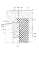
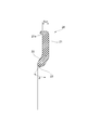
- the seal member 20 has a ring-shaped base portion 21 extending along the radial direction and an inner ring extending obliquely from the radial inner end of the base portion 21 to the inner side in the radial direction and the outer side in the axial direction. It has a lip portion 22 that comes into contact with the outer peripheral surface of the twelve. Further, as shown in FIG. 4, the outer end portion of the base portion 21 of the seal member 20 alone before being attached to the outer ring 11 has a protruding portion extending in the axially outward direction when attached to the outer ring 11. Has 21a.
- the outer peripheral portion of the seal member 20 is fixed to the seal mounting groove 15 formed at one end in the axial direction (left end in FIG. 2) of the inner peripheral surface of the outer ring 11 by the retaining ring 30.
- the retaining ring 30 is preferably a ring-shaped member having a rectangular cross section, such as a C-shaped retaining ring, which is partially divided. Further, the outer diameter of the seal member 20 is set to be larger than the outer diameter of the retaining ring 30 in the seal mounting groove 15.
- Examples of the material of the seal member 20 include water-resistant acrylic rubber having a shore A hardness (JIS K 6253) of 60 to 90, general water-resistant fluorine rubber having a shore A hardness of 60 to 90, and the like. By using the above-mentioned material, the seal member 20 can obtain appropriate elastic properties and can improve durability and wear resistance.
- An inclined surface 12b with which the lip portion 22 of the seal member 20 contacts is formed at one end in the axial direction (left end in FIG. 2) of the outer peripheral surface of the inner ring 12.
- the inclined surface 12b is formed so as to gradually reduce in diameter toward the outer side in the axial direction.
- the seal mounting groove 15 is provided on the outer side of the groove bottom surface 15a in which the outer peripheral surface of the seal member 20 contacts and the groove bottom surface 15a in the axial direction, and the groove bottom surface 15a and the outer inner peripheral surface 11b1 of the outer ring 11 are provided. It has a tapered surface 15b with which the retaining ring 30 contacts, and a groove inner surface 15c provided inside the groove bottom surface 15a in the axial direction and with which the axial inner surface of the seal member 20 contacts.
- the tapered surface 15b is formed so as to gradually increase in diameter toward the inside in the axial direction.
- the outer inner peripheral surface 11b1 is a cylindrical surface formed between the outer end portion of the seal mounting groove 15 (the outer end portion 15b1 of the tapered surface 15b) and the axial end surface of the outer ring 11.
- the seal member 20 is fitted into the seal mounting groove 15, and the retaining ring 30 is fitted into the seal mounting groove 15, so that the diameter of the retaining ring 30 is expanded and the outer peripheral edge of the outer peripheral surface of the retaining ring 30 in the axial direction is formed. It contacts the tapered surface 15b of the seal mounting groove 15.
- the force that tends to spread outward in the radial direction of the retaining ring 30 is converted into a force that presses the seal member 20 inward in the axial direction (pushing pressure in the thrust direction) by the tapered surface 15b, and the base 21 of the seal member 20 Is sandwiched between the retaining ring 30 and the groove inner side surface 15c.
- the protruding portion 21a which is a part of the radial outer end portion of the seal member 20, protrudes in the direction of the tapered surface 15b of the seal mounting groove 15, it is preferable that the inner peripheral surface of the seal mounting groove 15 (this In the embodiment, the groove bottom surface 15a) is sandwiched between the outer peripheral surface of the stop ring 30, and the protruding portion 21a is elastically deformed in the radial direction by a force that tends to spread outward in the radial direction of the stop ring 30.
- the inner peripheral surface of the seal mounting groove 15 that sandwiches the radial outer end of the seal member 20 may include a tapered surface 15b.
- the protruding portion 21a protrudes in the direction of the tapered surface 15b of the seal mounting groove 15 and is caught on the outer peripheral surface of the retaining ring 30, so that a binding force in the radial direction of the seal member 20 is generated.
- the protruding portion 21a which is a part of the radial outer end portion of the seal member 20, is sandwiched between the inner peripheral surface of the seal mounting groove 15 and the outer peripheral surface of the retaining ring 30, so that the seal member 20 is radial.
- Directional binding force is generated. That is, in the present embodiment, a binding force in the radial direction of the seal member 20 that is not in the prior art is generated.
- a space S is formed between the inner peripheral surface of the seal mounting groove 15 and the outer peripheral surface of the retaining ring 30. Is preferable.
- the radial outer end portion of the seal member 20 projects in the direction of the tapered surface 15b of the seal mounting groove 15 and is caught on the outer peripheral surface of the retaining ring 30. , A binding force in the radial direction of the seal member 20 is generated.
- a binding force in the radial direction of the seal member 20 can be generated. As a result, the binding force of the seal member 20 can be further increased.
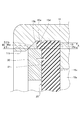
- FIG. 5 is an enlarged cross-sectional view of the periphery of the retaining ring 30 in the second embodiment.
- the rolling bearing 10 of the second embodiment is different from the first embodiment in that the protrusion 15d is provided in the seal mounting groove 15.
- the configuration other than the protrusion 15d of the second embodiment is the same as the configuration of the first embodiment, and thus the description thereof will be omitted.
- a protrusion 15d protruding inward in the radial direction is provided on the groove bottom surface 15a of the seal mounting groove 15 of the outer ring 11.
- the protrusion 15d faces the outer peripheral surface 30a of the retaining ring 30 in the radial direction (vertical direction in FIG. 5). That is, the protrusion 15d and the outer peripheral surface 30a of the retaining ring 30 overlap in the axial direction (left-right direction in FIG. 5).
- the protrusion 15d is located on the inner side in the axial direction (on the right side in FIG. 5) with respect to the tip 21b of the protrusion 21a of the seal member 20. That is, the protrusion 15d and the protrusion 21a of the seal member 20 overlap in the axial direction.
- the radial distance A between the inner peripheral surface of the protrusion 15d and the outer peripheral surface 30a of the retaining ring 30 is the groove bottom surface 15a of the seal mounting groove 15 and the outer peripheral surface 30a of the retaining ring 30 in the vicinity of the tip 21b of the protruding portion 21a. Is shorter than the radial distance B (A ⁇ B).
- the tip 21b of the protrusion 21a (the portion of the protrusion 21a that is axially outside the protrusion 15d) is constrained in the thrust direction, so that the restraining force of the seal member 20 can be further increased.
- the protrusion 15d may be formed on the entire circumference of the groove bottom surface 15a of the seal mounting groove 15, or may be formed on a part of the groove bottom surface 15a.
- the protrusion 15d is formed in an annular shape on the entire circumference of the groove bottom surface 15a, the seal member 20 is hard to come off and the protrusion 15d can be easily processed.
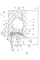
- FIG. 6 is a cross-sectional view showing a stopped state of the rolling bearing of the third embodiment.
- the rolling bearing 10 of the third embodiment has the same configuration as that of the first embodiment, but the dimensional relationship between the seal member 20 and the members around the seal member 20 will be mainly described below. Further, the same or equivalent reference numerals are given to the same configurations as those of the first embodiment, and the description thereof is omitted.
- the inclination angle ⁇ of the lip portion 22 with respect to the base portion 21 of the seal member 20, that is, the angle formed by the radial direction of the base portion 21 and the extension direction of the lip portion 22 is 10 ° to 80. It is set to °. If the inclination angle ⁇ is smaller than the above range, the contact resistance becomes excessive, and if it is large, the flow resistance of the compressed air becomes excessive.
- the inclination angle ⁇ is preferably 20 ° to 60 °, more preferably 25 ° to 50 °.
- the lip portion 22 is inclined toward the downstream side (axial direction outer side) of the compressed air supply direction toward the inner side in the radial direction, and can come into contact with the inclined surface 12b of the inner ring 12.
- the shape of the inner peripheral surface 23 of the lip portion 22 is an annular shape (conical surface shape).
- the shape of the inclined surface 12b of the inner ring 12 with which the lip portion 22 can come into contact is also an annular shape (conical surface shape). Therefore, the inner peripheral surface 23 of the lip portion 22 can come into contact with the inclined surface of the inner ring 12 over the entire circumference. That is, the sealing member 20 can seal the bearing internal space 10a between the inner peripheral surface 11b of the outer ring 11 and the outer peripheral surface 12c of the inner ring 12 over the entire circumference.
- the supplied compressed air flows into the bearing internal space 10a, and the pressure of the compressed air acts on the seal member 20. Then, the lip portion 22 is elastically deformed toward the downstream side of the flow of compressed air. As a result, the contact area between the inner peripheral surface 23 of the lip portion 22 and the inclined surface 12b of the inner ring 12 becomes smaller than in the case where the pressure of the compressed air does not act. That is, the lip portion 22 is in an open state in which compressed air is communicated.
- the seal member 20 does not have a core metal and is made of only an elastic material, it has a structure that is easily elastically deformed as a whole.
- the lip portion 22 does not interfere with the retaining ring 30 at all, the seal member 20 is in a state of being easily elastically deformed and supported by the outer ring 11. Therefore, when compressed air acts on the seal member 20 beyond a specific pressure, the inner peripheral portion of the seal member 20 is elastically deformed toward the outer side in the axial direction, and the inner peripheral surface 23 of the lip portion 22 and the inner ring 12 are inclined. The contact area with the surface 12b becomes smaller.
- the air turbine can be started smoothly, the frictional resistance between the seal member 20 and the inner ring 12 can be reduced, and the rotation shaft 101 can be rotated at an ultra-high speed of about 400,000 min-1. Further, since the inclined surface 12b is provided at the end portion of the outer peripheral surface 12c of the inner ring 12 on the downstream side in the supply direction of the compressed air, the flow of the compressed air passing between the lip portion 22 and the inclined surface 12b becomes smooth. , It is possible to realize ultra-high speed rotation that is even faster than before.
- both side surfaces of the base portion 21 of the seal member 20 in the axial direction are the seal mounting groove 15 of the retaining ring 30 and the outer ring 11.
- the outer ring 11 is formed so as to satisfy the following equation (1). 0.018 ⁇ Lss / ⁇ dg ⁇ 0.093 ... (1)
- Lss / ⁇ dg By setting Lss / ⁇ dg to 0.018 or more, it is possible to secure a radial length in which the base 21 of the seal member 20 is sandwiched between the retaining ring 30 and the seal mounting groove 15 of the outer ring 11, and compressed air is supplied. When this is done, it is possible to reliably prevent the seal member 20 from coming off the seal mounting groove 15 of the outer ring 11.
- Lss / ⁇ dg is preferably 0.027 or more, and is 0. More preferably, it is .035 or more.
- Lss / ⁇ dg is preferably 0.074 or less, and more preferably 0.047 or less.
- the inner diameter of the retaining ring 30 is smaller than the inner diameter of the outer ring 11, and the inner circumference of the retaining ring 30 is smaller.
- the surface is located on the inner diameter side of the inner peripheral surface of the outer ring 11.
- the gap in the circumferential direction of the retaining ring 30 when the sealing member 20 and the retaining ring 30 are attached to the seal mounting groove 15 of the outer ring 11 is defined as Ts, and the retaining ring of the sealing member 20.
- the ratio of Ts to Sct is formed so as to satisfy the following formula (2). 1 ⁇ Ts / Sct ⁇ 10 ... (2)
- Ts / Sct is preferably 6 or less, and more preferably 5 or less.
- Ts / Sct may be 1 or more, preferably 2 or more, and more preferably 2.5 or more.
- the seal member 20 has a radial length from the axially inner inclined start portion R of the lip portion 22 to the outermost diameter position of the contact portion with the outer peripheral surface 12c of the inner ring 12 Skn. Assuming that the thickness of the lip portion 22 in the inclined direction is Skt, the lip portion 22 is formed so as to satisfy the following equation (3). 0.25 ⁇ Skn / Skt ⁇ 2.5 ... (3)
- Skn / Skt By setting Skn / Skt to 0.25 or more, the length of the lip portion 22 that receives the compressed air can be secured, and the seal member 20 can be brought into contact with the outer peripheral surface 12c of the inner ring 12 at an appropriate angle. Since the lip portion 22 is also easily deformed, the sealing member 20 is likely to be in non-contact with the outer peripheral surface 12c of the inner ring 12 even with a small amount of compressed air.
- Skn / Skt is preferably 0.65 or more, and more preferably 0.90 or more.
- Skn / Skt when Skn / Skt is larger than 2.5, the length of the lip portion 22 becomes too long, the pressing force of the inner ring 12 against the outer peripheral surface 12c becomes large, and it is difficult to make contact at an appropriate angle. If the amount of compressed air is small, the seal member 20 is unlikely to come into non-contact with the outer peripheral surface 12c of the inner ring 12. Therefore, Skn / Skt may be 2.5 or less, preferably 2.1 or less, and more preferably 1.75 or less.
- the outermost diameter position of the contact portion of the inner ring 12 of the seal member 20 with the outer peripheral surface 12c is the boundary portion between the inclined surface 12b and the cylindrical surface on the outer peripheral surface 12c of the inner ring 12.
- the outermost diameter position may be an intermediate portion of the inclined surface 12b.
- the portion of the seal member 20 in contact with the retaining ring 30, that is, the axial thickness Sct of the base portion 21 and the inclined portion 22 thickness Skt in the inclined direction may be the same thickness. However, it may be different.
- the seal member 20 between the inclination start portion R on the inner side in the axial direction of the lip portion 22 and the inner diameter of the retaining ring 30 when the seal member 20 and the retaining ring 30 are attached to the seal mounting groove 15 of the outer ring 11.
- the ratio of the above-mentioned radial length Skn to Scn is formed so as to satisfy the following formula (4). 0.21 ⁇ Skn / Scn ⁇ 4.7 ... (4)
- the length of the lip portion 22 that receives compressed air can be secured between the inner diameter of the stop ring 30 and the outer peripheral surface 12c of the inner ring 12, and the seal member 20 can be secured. Can be brought into contact with the outer peripheral surface 12c of the inner ring 12 at an appropriate angle, so that the seal member 20 tends to be in non-contact with the outer peripheral surface 12c of the inner ring 12 even with a small amount of compressed air.
- the Skn / Scn is preferably 0.42 or more so that the seal member 20 can easily come into non-contact with the outer peripheral surface 12c of the inner ring 12.
- Skn / Scn when Skn / Scn is larger than 4.7, the length of the lip portion 22 becomes too long and cannot be brought into contact with the outer peripheral surface 12c of the inner ring 12 at an appropriate angle, resulting in a small amount of compressed air. , The seal member 20 is unlikely to come into non-contact with the outer peripheral surface 12c of the inner ring 12. Therefore, Skn / Scn may be 4.7 or less, and preferably 1.6 or less.
- the length of the lip portion 22 that receives compressed air can be secured even for a rolling bearing having a predetermined size, and the sealing member 20 has an appropriate angle with respect to the outer peripheral surface 12c of the inner ring 12. Therefore, even if the amount of compressed air is small, the seal member 20 tends to be in non-contact from the outer peripheral surface 12c of the inner ring 12.
- 0.065 ⁇ Skn / Ngn ⁇ 0.21 is preferable, and 0.090 ⁇ Skn / Ngn ⁇ 0.18. Is more preferable.
- the seal member 20 has a radial length from the axially outer inclined start portion Q of the lip portion 22 to the outermost diameter position of the contact portion with the outer peripheral surface 12c of the inner ring 12 in Sks.
- the lip portion 22 is formed so as to satisfy the following equation (6). 0.5 ⁇ Sks / Sct ⁇ 3 ... (6)
- the length of the lip portion 22 for receiving compressed air and opening to the outside of the bearing can be secured, and the sealing member 20 is suitable for the outer peripheral surface 12c of the inner ring 12. Since the contact can be made at any angle, the seal member 20 tends to be in non-contact with the outer peripheral surface 21 of the inner ring 20 even with a small amount of compressed air.
- Sks / Sct is preferably 0.75 or more, and more preferably 1 or more.
- Sks / Sct when Sks / Sct is larger than 3, the length of the lip portion 22 becomes too long, the pressing force of the inner ring 12 against the outer peripheral surface 12c becomes large, or it becomes difficult to make contact at an appropriate angle. Therefore, if the amount of compressed air is small, the seal member 20 is unlikely to come into non-contact with the outer peripheral surface 12c of the inner ring 12. Therefore, Sks / Sct may be 3 or less, preferably 2.5 or less, and more preferably 2 or less.
- the seal member 20 between the axially outer inclined start portion Q of the lip portion 22 and the inner diameter of the retaining ring 30 when the seal member 20 and the retaining ring 30 are attached to the seal mounting groove 15 of the outer ring 11.
- the ratio of the above-mentioned radial length Sks to Scs is formed so as to satisfy the following formula (7). 0.35 ⁇ Sks / Scs ⁇ 3.75 ... (7)
- the length of the lip portion 22 that receives compressed air can be secured between the inner diameter of the stop ring 30 and the outer peripheral surface 12c of the inner ring 12, and the seal member 20 can be secured. Can be brought into contact with the outer peripheral surface 12c of the inner ring 12 at an appropriate angle, so that the seal member 20 tends to be in non-contact with the outer peripheral surface 12c of the inner ring 12 even with a small amount of compressed air.
- the Sks / Scs is preferably 0.62 or more in order for the seal member 20 to easily become non-contact from the outer peripheral surface 12c of the inner ring 12.
- Sks / Scs when Sks / Scs is larger than 3.75, the length of the lip portion 22 becomes too long and cannot be brought into contact with the outer peripheral surface 12c of the inner ring 12 at an appropriate angle, resulting in a small amount of compressed air. , The seal member 20 is unlikely to come into non-contact with the outer peripheral surface 12c of the inner ring 12. Therefore, Sks / Scs may be 3.75 or less, and preferably 2.0 or less.
- the length of the lip portion 22 that receives compressed air can be secured even for a rolling bearing having a predetermined size, and the sealing member 20 has an appropriate angle with respect to the outer peripheral surface 12c of the inner ring 12. Therefore, even if the amount of compressed air is small, the seal member 20 tends to be in non-contact from the outer peripheral surface 12c of the inner ring 12. It is preferable that 0.10 ⁇ Sks / Ngn ⁇ 0.23 in order to make the seal member 20 easily non-contact from the outer peripheral surface 12c of the inner ring 12.
- the radial length between the inner peripheral surface 11b of the outer ring 11 and the inner peripheral surface of the retaining ring 30 in a state where the seal member 20 is fixed to the seal mounting groove 15 of the outer ring 11 by the retaining ring 30 is Tm.
- the ratio of Tm to An is formed so as to satisfy the following equation (9). .. 0 ⁇ Tm / An ⁇ 0.5 ... (9)
- Tm / An By setting Tm / An to 0 or more, the seal member 20 is less likely to come off from the outer ring 11 even when compressed air is supplied. Considering the tolerances such as the depth and angle of the seal mounting groove 15 of the outer ring 11 and the radial thickness of the retaining ring 30, Tm / An is preferably 0.05 or more, preferably 0.12 or more. Is more preferable.
- Tm / An when compressed air is supplied, the seal member 20 tends to be in non-contact with the outer peripheral surface 21 of the inner ring 20.
- the Tm / An is preferably 0.28 or less in order for the seal member 20 to easily become non-contact from the outer peripheral surface 12c of the inner ring 12.
- the sealing member 20 when the compressed air is supplied, the sealing member 20 is in non-contact from the outer peripheral surface 12c of the inner ring 12 even with a small amount of compressed air for energy saving. And the seal member 20 is less likely to come off the seal mounting groove 15 of the outer ring 11.
- the lip portion 22 returns to the state shown in FIG. 6, and the inner peripheral surface 23 of the lip portion 22 comes into contact with the inclined surface 12b of the inner ring 12 over the entire circumference. That is, the lip portion 22 is closed, and the lip portion 22 functions as a brake for the inner ring 12.
- the maximum braking effect due to the frictional resistance between the seal member 20 and the inner ring 12 can be obtained. This makes it possible to stop the rotating shaft 121 fixed to the inner ring 12 most quickly.
- the radial length between the inner peripheral surface of the retaining ring 30 and the outer peripheral surface 12c of the inner ring 12 in a state where the seal member 20 is fixed to the seal mounting groove 15 of the outer ring 11 by the retaining ring 30 is set to San.
- the ratio of the axial thickness Sct of the base portion 21 to San is formed so as to satisfy the following formula (10). 0.1 ⁇ Sct / San ⁇ 0.6 ... (10)
- Sct / San By setting Sct / San to 0.1 or more, the seal member 20 can be pressed against the inner ring 12 and the air turbine can be quickly stopped when compressed air is no longer supplied.
- Sct / San is preferably 0.15 or more, and more preferably 0.2 or more.
- the Sct / San is preferably 0.4 or less, and more preferably 0.3 or less, in order for the seal member 20 to easily become non-contact from the outer peripheral surface 12c of the inner ring 12.
- Thn / Lss is preferably 0.08 or more, and is 0. More preferably, it is 10.10 or more.
- Thn / Lss is preferably 0.8 or less, and more preferably 0.6 or less.
- the lip portion 22 of the seal member 20 which is particularly easily elastically deformed, is configured to be in contact with the inclined surface 12b of the inner ring 12, the contact pressure between the seal member 20 and the inclined surface 12b is compared with the case where the contact pressure is in radial direction. Can be reduced. As a result, the opening / closing operation of the sealing member 20 by compressed air can be performed smoothly and with high responsiveness. Further, the contact pressure can be reduced with a pressure of compressed air smaller than that of the conventional structure, and the rotation speed of the rotating shaft 121 can be further improved and the stop time can be shortened at the same time.
- the lip portion 22 at the tip of the seal member 20 With a contact surface that comes into surface contact with the inclined surface 12b of the inner ring 12, the surface pressure acting on the seal member 20 is reduced, and wear is reduced. In addition, the sealing property is improved by increasing the contact area. Further, the contact surface of the lip portion 22 may be a surface that makes line contact with the inclined surface 12b of the inner ring 12. In that case, the frictional resistance is reduced as compared with the case of surface contact, which is advantageous for high-speed rotation.
- a pair of rolling bearings are arranged on the rotating shaft 121, but the sealing member 20 is arranged at one end in the axial direction opposite to the inlet of the compressed air of the outer ring 11. NS.
- lubricating oil can be supplied into each rolling bearing from the bearing end side where the seal member 20 is not arranged.
- the seal member 20 is arranged on the opposite side of the spray lubrication side, liquid does not leak from each rolling bearing to the outside of the head portion 110.
- dental air turbine handpieces are autoclaved for high temperature cleaning and sterilization after use.
- the amount of lubricating oil in the rolling bearing is reduced by this treatment, since the sealing member 20 is arranged only at one end in the axial direction of the rolling bearing, the lubricating oil can be easily supplied from the other end in the axial direction. Therefore, the rolling bearing can always be in a good lubrication state, and the rotary shaft 121 can be stably driven to rotate.
- the present invention is not limited to those illustrated in each of the above embodiments, and can be appropriately modified without departing from the gist of the present invention.
- the retaining ring is not limited to a rectangular cross section, and may have a circular cross section.
- the retaining ring may be formed with a tapered surface, and the seal mounting groove may be formed with a rectangular cross section so that the tapered surface of the retaining ring is brought into contact with the corner portion of the seal mounting groove having a rectangular cross section.
- the rim portion 7 on one end side is arranged on the upstream side in the compressed air supply direction with respect to the ball 3, but the rim portion 7 is not limited to this. May be arranged on the seal member side opposite to the axial direction.
- the seal member is arranged only on one end side in the axial direction of the rolling bearing 1, the groove portion 13 of the outer ring 10 and the inclined surface 12b of the inner ring 20 are formed only on one end side in the axial direction, but the present invention is not limited to this.
- the configuration may be formed symmetrically on the other end side in the axial direction. In that case, one of the pair of inclined surfaces is not used, but in the process of assembling the rolling bearing, it is not necessary to be aware of the assembling direction, and the work process can be simplified.
- the seal member may have a constant wall thickness at the inclined portion, but may be gradually reduced toward the inside in the radial direction.
- the thickness Skt of the inclined portion 33 in the inclined direction is the thickness of the thickest portion.
- Radial length between An and the radial length between the inner peripheral surface of the outer ring and the outer peripheral surface of the inner ring San The inner peripheral surface of the retaining ring when the seal member is fixed to the groove of the outer ring by the retaining ring.
- Axial length between the inner ring and the outer peripheral surface of the inner ring. Axial length of the Lss seal member that is sandwiched by both sides of the seal member in contact with both the retaining ring and the groove of the outer ring. The radial distance between the outer peripheral surface and the outer end of the tapered surface of the groove
Landscapes
- Engineering & Computer Science (AREA)
- General Engineering & Computer Science (AREA)
- Health & Medical Sciences (AREA)
- Mechanical Engineering (AREA)
- Oral & Maxillofacial Surgery (AREA)
- Epidemiology (AREA)
- Dentistry (AREA)
- Life Sciences & Earth Sciences (AREA)
- Animal Behavior & Ethology (AREA)
- General Health & Medical Sciences (AREA)
- Public Health (AREA)
- Veterinary Medicine (AREA)
- Rolling Contact Bearings (AREA)
Priority Applications (4)
| Application Number | Priority Date | Filing Date | Title |
|---|---|---|---|
| US17/910,154 US20230131486A1 (en) | 2020-03-12 | 2021-03-12 | Rolling bearing |
| JP2022506863A JPWO2021182637A1 (https=) | 2020-03-12 | 2021-03-12 | |
| EP21768365.5A EP4119808A4 (en) | 2020-03-12 | 2021-03-12 | Rolling bearing |
| CN202180020833.2A CN115280029B (zh) | 2020-03-12 | 2021-03-12 | 滚动轴承 |
Applications Claiming Priority (4)
| Application Number | Priority Date | Filing Date | Title |
|---|---|---|---|
| JP2020042731 | 2020-03-12 | ||
| JP2020-042731 | 2020-03-12 | ||
| JP2021-017471 | 2021-02-05 | ||
| JP2021017471 | 2021-02-05 |
Publications (1)
| Publication Number | Publication Date |
|---|---|
| WO2021182637A1 true WO2021182637A1 (ja) | 2021-09-16 |
Family
ID=77672058
Family Applications (1)
| Application Number | Title | Priority Date | Filing Date |
|---|---|---|---|
| PCT/JP2021/010228 Ceased WO2021182637A1 (ja) | 2020-03-12 | 2021-03-12 | 転がり軸受 |
Country Status (5)
| Country | Link |
|---|---|
| US (1) | US20230131486A1 (https=) |
| EP (1) | EP4119808A4 (https=) |
| JP (1) | JPWO2021182637A1 (https=) |
| CN (1) | CN115280029B (https=) |
| WO (1) | WO2021182637A1 (https=) |
Cited By (1)
| Publication number | Priority date | Publication date | Assignee | Title |
|---|---|---|---|---|
| WO2026023151A1 (ja) * | 2024-07-22 | 2026-01-29 | 日本精工株式会社 | 転がり軸受用シール部材 |
Citations (6)
| Publication number | Priority date | Publication date | Assignee | Title |
|---|---|---|---|---|
| JPH02135369U (https=) * | 1989-04-17 | 1990-11-09 | ||
| JP2003240000A (ja) * | 2002-02-18 | 2003-08-27 | Hitachi Constr Mach Co Ltd | 軸受装置 |
| JP2007333142A (ja) * | 2006-06-16 | 2007-12-27 | Nsk Ltd | 転がり軸受 |
| JP2017211076A (ja) | 2016-05-19 | 2017-11-30 | 日本精工株式会社 | 転がり軸受及びエアタービン用軸受ユニット |
| JP2020042731A (ja) | 2018-09-13 | 2020-03-19 | 株式会社三菱Ufj銀行 | 取引情報のモニタリング方法および取引情報モニタリングシステム |
| JP2021017471A (ja) | 2019-07-18 | 2021-02-15 | 日本化薬株式会社 | インク、インクセット、ならびにそれらを用いた印刷方法 |
Family Cites Families (6)
| Publication number | Priority date | Publication date | Assignee | Title |
|---|---|---|---|---|
| US2886347A (en) * | 1956-10-29 | 1959-05-12 | Marlin Rockwell Corp | Seals for rotatable members |
| US3003835A (en) * | 1958-06-30 | 1961-10-10 | Bendix Corp | Seal for grease lubricated bearing |
| US3226168A (en) * | 1963-01-18 | 1965-12-28 | Fed Bearings Co Inc | Composite seal construction for antifriction bearings |
| JP3157077B2 (ja) * | 1994-02-16 | 2001-04-16 | 内山工業株式会社 | ベアリングシール |
| EP3667110B1 (en) * | 2016-03-07 | 2021-07-07 | NSK Ltd. | Rolling bearing for a roller bearing unit for air turbine and air turbine handpiece for dental use |
| JP7367321B2 (ja) * | 2019-03-28 | 2023-10-24 | 日本精工株式会社 | 転がり軸受 |
-
2021
- 2021-03-12 CN CN202180020833.2A patent/CN115280029B/zh active Active
- 2021-03-12 JP JP2022506863A patent/JPWO2021182637A1/ja active Pending
- 2021-03-12 WO PCT/JP2021/010228 patent/WO2021182637A1/ja not_active Ceased
- 2021-03-12 US US17/910,154 patent/US20230131486A1/en not_active Abandoned
- 2021-03-12 EP EP21768365.5A patent/EP4119808A4/en not_active Withdrawn
Patent Citations (6)
| Publication number | Priority date | Publication date | Assignee | Title |
|---|---|---|---|---|
| JPH02135369U (https=) * | 1989-04-17 | 1990-11-09 | ||
| JP2003240000A (ja) * | 2002-02-18 | 2003-08-27 | Hitachi Constr Mach Co Ltd | 軸受装置 |
| JP2007333142A (ja) * | 2006-06-16 | 2007-12-27 | Nsk Ltd | 転がり軸受 |
| JP2017211076A (ja) | 2016-05-19 | 2017-11-30 | 日本精工株式会社 | 転がり軸受及びエアタービン用軸受ユニット |
| JP2020042731A (ja) | 2018-09-13 | 2020-03-19 | 株式会社三菱Ufj銀行 | 取引情報のモニタリング方法および取引情報モニタリングシステム |
| JP2021017471A (ja) | 2019-07-18 | 2021-02-15 | 日本化薬株式会社 | インク、インクセット、ならびにそれらを用いた印刷方法 |
Non-Patent Citations (1)
| Title |
|---|
| See also references of EP4119808A4 |
Cited By (1)
| Publication number | Priority date | Publication date | Assignee | Title |
|---|---|---|---|---|
| WO2026023151A1 (ja) * | 2024-07-22 | 2026-01-29 | 日本精工株式会社 | 転がり軸受用シール部材 |
Also Published As
| Publication number | Publication date |
|---|---|
| US20230131486A1 (en) | 2023-04-27 |
| EP4119808A4 (en) | 2023-08-02 |
| JPWO2021182637A1 (https=) | 2021-09-16 |
| CN115280029B (zh) | 2025-11-07 |
| EP4119808A1 (en) | 2023-01-18 |
| CN115280029A (zh) | 2022-11-01 |
Similar Documents
| Publication | Publication Date | Title |
|---|---|---|
| CN111503161B (zh) | 滚动轴承和空气涡轮机用轴承单元以及牙科空气涡轮机手持件 | |
| JP2004162879A (ja) | 転がり軸受用樹脂保持器 | |
| US11540902B2 (en) | Rolling bearing, bearing unit for air turbine, and air turbine handpiece for dental use | |
| JP6686738B2 (ja) | 転がり軸受及びエアタービン用軸受ユニット | |
| WO2016104556A1 (ja) | エアタービン用軸受ユニット | |
| WO2021182637A1 (ja) | 転がり軸受 | |
| JP2011127702A (ja) | 転がり軸受 | |
| US11564772B2 (en) | Rolling bearing, bearing unit for air turbine, and air turbine handpiece for dental use | |
| EP4083453B1 (en) | Rolling bearing for air turbine | |
| EP4083454B1 (en) | Rolling bearing for air turbine | |
| WO2011074468A1 (ja) | 転がり軸受 | |
| JP7367321B2 (ja) | 転がり軸受 | |
| WO2006093235A1 (ja) | スラスト円筒ころ軸受 | |
| JP7799905B2 (ja) | 軸受 | |
| JP2004340277A (ja) | 転がり軸受用冠形保持器及び転がり軸受 | |
| JP2004332906A (ja) | 転がり軸受用保持器及び転がり軸受 | |
| CN114718956A (zh) | 保持器、滚动轴承、轴承单元和旋转设备 | |
| JPS61211530A (ja) | 十字軸型ユニバ−サルジヨイント用軸受装置 |
Legal Events
| Date | Code | Title | Description |
|---|---|---|---|
| 121 | Ep: the epo has been informed by wipo that ep was designated in this application |
Ref document number: 21768365 Country of ref document: EP Kind code of ref document: A1 |
|
| ENP | Entry into the national phase |
Ref document number: 2022506863 Country of ref document: JP Kind code of ref document: A |
|
| WWE | Wipo information: entry into national phase |
Ref document number: 202217051575 Country of ref document: IN |
|
| NENP | Non-entry into the national phase |
Ref country code: DE |
|
| ENP | Entry into the national phase |
Ref document number: 2021768365 Country of ref document: EP Effective date: 20221012 |
|
| WWW | Wipo information: withdrawn in national office |
Ref document number: 2021768365 Country of ref document: EP |
|
| WWG | Wipo information: grant in national office |
Ref document number: 202180020833.2 Country of ref document: CN |