WO2021182358A1 - 成形システム、及び成形方法 - Google Patents
成形システム、及び成形方法 Download PDFInfo
- Publication number
- WO2021182358A1 WO2021182358A1 PCT/JP2021/008833 JP2021008833W WO2021182358A1 WO 2021182358 A1 WO2021182358 A1 WO 2021182358A1 JP 2021008833 W JP2021008833 W JP 2021008833W WO 2021182358 A1 WO2021182358 A1 WO 2021182358A1
- Authority
- WO
- WIPO (PCT)
- Prior art keywords
- molding
- molded product
- metal pipe
- pipe material
- scale
- Prior art date
- Legal status (The legal status is an assumption and is not a legal conclusion. Google has not performed a legal analysis and makes no representation as to the accuracy of the status listed.)
- Ceased
Links
Images




Classifications
-
- B—PERFORMING OPERATIONS; TRANSPORTING
- B21—MECHANICAL METAL-WORKING WITHOUT ESSENTIALLY REMOVING MATERIAL; PUNCHING METAL
- B21D—WORKING OR PROCESSING OF SHEET METAL OR METAL TUBES, RODS OR PROFILES WITHOUT ESSENTIALLY REMOVING MATERIAL; PUNCHING METAL
- B21D26/00—Shaping without cutting otherwise than using rigid devices or tools or yieldable or resilient pads, i.e. applying fluid pressure or magnetic forces
- B21D26/02—Shaping without cutting otherwise than using rigid devices or tools or yieldable or resilient pads, i.e. applying fluid pressure or magnetic forces by applying fluid pressure
- B21D26/033—Deforming tubular bodies
- B21D26/041—Means for controlling fluid parameters, e.g. pressure or temperature
-
- B—PERFORMING OPERATIONS; TRANSPORTING
- B23—MACHINE TOOLS; METAL-WORKING NOT OTHERWISE PROVIDED FOR
- B23P—METAL-WORKING NOT OTHERWISE PROVIDED FOR; COMBINED OPERATIONS; UNIVERSAL MACHINE TOOLS
- B23P23/00—Machines or arrangements of machines for performing specified combinations of different metal-working operations not covered by a single other subclass
- B23P23/04—Machines or arrangements of machines for performing specified combinations of different metal-working operations not covered by a single other subclass for both machining and other metal-working operations
-
- B—PERFORMING OPERATIONS; TRANSPORTING
- B21—MECHANICAL METAL-WORKING WITHOUT ESSENTIALLY REMOVING MATERIAL; PUNCHING METAL
- B21D—WORKING OR PROCESSING OF SHEET METAL OR METAL TUBES, RODS OR PROFILES WITHOUT ESSENTIALLY REMOVING MATERIAL; PUNCHING METAL
- B21D26/00—Shaping without cutting otherwise than using rigid devices or tools or yieldable or resilient pads, i.e. applying fluid pressure or magnetic forces
- B21D26/02—Shaping without cutting otherwise than using rigid devices or tools or yieldable or resilient pads, i.e. applying fluid pressure or magnetic forces by applying fluid pressure
- B21D26/033—Deforming tubular bodies
- B21D26/035—Deforming tubular bodies including an additional treatment performed by fluid pressure, e.g. perforating
-
- B—PERFORMING OPERATIONS; TRANSPORTING
- B21—MECHANICAL METAL-WORKING WITHOUT ESSENTIALLY REMOVING MATERIAL; PUNCHING METAL
- B21D—WORKING OR PROCESSING OF SHEET METAL OR METAL TUBES, RODS OR PROFILES WITHOUT ESSENTIALLY REMOVING MATERIAL; PUNCHING METAL
- B21D26/00—Shaping without cutting otherwise than using rigid devices or tools or yieldable or resilient pads, i.e. applying fluid pressure or magnetic forces
- B21D26/02—Shaping without cutting otherwise than using rigid devices or tools or yieldable or resilient pads, i.e. applying fluid pressure or magnetic forces by applying fluid pressure
- B21D26/033—Deforming tubular bodies
- B21D26/039—Means for controlling the clamping or opening of the moulds
-
- B—PERFORMING OPERATIONS; TRANSPORTING
- B21—MECHANICAL METAL-WORKING WITHOUT ESSENTIALLY REMOVING MATERIAL; PUNCHING METAL
- B21D—WORKING OR PROCESSING OF SHEET METAL OR METAL TUBES, RODS OR PROFILES WITHOUT ESSENTIALLY REMOVING MATERIAL; PUNCHING METAL
- B21D26/00—Shaping without cutting otherwise than using rigid devices or tools or yieldable or resilient pads, i.e. applying fluid pressure or magnetic forces
- B21D26/02—Shaping without cutting otherwise than using rigid devices or tools or yieldable or resilient pads, i.e. applying fluid pressure or magnetic forces by applying fluid pressure
- B21D26/033—Deforming tubular bodies
- B21D26/047—Mould construction
-
- B—PERFORMING OPERATIONS; TRANSPORTING
- B21—MECHANICAL METAL-WORKING WITHOUT ESSENTIALLY REMOVING MATERIAL; PUNCHING METAL
- B21D—WORKING OR PROCESSING OF SHEET METAL OR METAL TUBES, RODS OR PROFILES WITHOUT ESSENTIALLY REMOVING MATERIAL; PUNCHING METAL
- B21D37/00—Tools as parts of machines covered by this subclass
- B21D37/16—Heating or cooling
-
- B—PERFORMING OPERATIONS; TRANSPORTING
- B23—MACHINE TOOLS; METAL-WORKING NOT OTHERWISE PROVIDED FOR
- B23K—SOLDERING OR UNSOLDERING; WELDING; CLADDING OR PLATING BY SOLDERING OR WELDING; CUTTING BY APPLYING HEAT LOCALLY, e.g. FLAME CUTTING; WORKING BY LASER BEAM
- B23K26/00—Working by laser beam, e.g. welding, cutting or boring
- B23K26/36—Removing material
- B23K26/38—Removing material by boring or cutting
-
- B—PERFORMING OPERATIONS; TRANSPORTING
- B23—MACHINE TOOLS; METAL-WORKING NOT OTHERWISE PROVIDED FOR
- B23K—SOLDERING OR UNSOLDERING; WELDING; CLADDING OR PLATING BY SOLDERING OR WELDING; CUTTING BY APPLYING HEAT LOCALLY, e.g. FLAME CUTTING; WORKING BY LASER BEAM
- B23K26/00—Working by laser beam, e.g. welding, cutting or boring
- B23K26/36—Removing material
- B23K26/38—Removing material by boring or cutting
- B23K26/382—Removing material by boring or cutting by boring
-
- B—PERFORMING OPERATIONS; TRANSPORTING
- B23—MACHINE TOOLS; METAL-WORKING NOT OTHERWISE PROVIDED FOR
- B23P—METAL-WORKING NOT OTHERWISE PROVIDED FOR; COMBINED OPERATIONS; UNIVERSAL MACHINE TOOLS
- B23P23/00—Machines or arrangements of machines for performing specified combinations of different metal-working operations not covered by a single other subclass
- B23P23/06—Metal-working plant comprising a number of associated machines or apparatus
-
- B—PERFORMING OPERATIONS; TRANSPORTING
- B24—GRINDING; POLISHING
- B24C—ABRASIVE OR RELATED BLASTING WITH PARTICULATE MATERIAL
- B24C1/00—Methods for use of abrasive blasting for producing particular effects; Use of auxiliary equipment in connection with such methods
-
- B—PERFORMING OPERATIONS; TRANSPORTING
- B24—GRINDING; POLISHING
- B24C—ABRASIVE OR RELATED BLASTING WITH PARTICULATE MATERIAL
- B24C1/00—Methods for use of abrasive blasting for producing particular effects; Use of auxiliary equipment in connection with such methods
- B24C1/003—Methods for use of abrasive blasting for producing particular effects; Use of auxiliary equipment in connection with such methods using material which dissolves or changes phase after the treatment, e.g. ice, CO2
-
- B—PERFORMING OPERATIONS; TRANSPORTING
- B24—GRINDING; POLISHING
- B24C—ABRASIVE OR RELATED BLASTING WITH PARTICULATE MATERIAL
- B24C1/00—Methods for use of abrasive blasting for producing particular effects; Use of auxiliary equipment in connection with such methods
- B24C1/08—Methods for use of abrasive blasting for producing particular effects; Use of auxiliary equipment in connection with such methods for polishing surfaces, e.g. smoothing a surface by making use of liquid-borne abrasives
- B24C1/086—Descaling; Removing coating films
-
- B—PERFORMING OPERATIONS; TRANSPORTING
- B24—GRINDING; POLISHING
- B24C—ABRASIVE OR RELATED BLASTING WITH PARTICULATE MATERIAL
- B24C11/00—Selection of abrasive materials or additives for abrasive blasts
-
- B—PERFORMING OPERATIONS; TRANSPORTING
- B24—GRINDING; POLISHING
- B24C—ABRASIVE OR RELATED BLASTING WITH PARTICULATE MATERIAL
- B24C5/00—Devices or accessories for generating abrasive blasts
-
- C—CHEMISTRY; METALLURGY
- C21—METALLURGY OF IRON
- C21D—MODIFYING THE PHYSICAL STRUCTURE OF FERROUS METALS; GENERAL DEVICES FOR HEAT TREATMENT OF FERROUS OR NON-FERROUS METALS OR ALLOYS; MAKING METAL MALLEABLE, e.g. BY DECARBURISATION OR TEMPERING
- C21D10/00—Modifying the physical properties by methods other than heat treatment or deformation
- C21D10/005—Modifying the physical properties by methods other than heat treatment or deformation by laser shock processing
-
- B—PERFORMING OPERATIONS; TRANSPORTING
- B23—MACHINE TOOLS; METAL-WORKING NOT OTHERWISE PROVIDED FOR
- B23P—METAL-WORKING NOT OTHERWISE PROVIDED FOR; COMBINED OPERATIONS; UNIVERSAL MACHINE TOOLS
- B23P15/00—Making specific metal objects by operations not covered by a single other subclass or a group in this subclass
-
- Y—GENERAL TAGGING OF NEW TECHNOLOGICAL DEVELOPMENTS; GENERAL TAGGING OF CROSS-SECTIONAL TECHNOLOGIES SPANNING OVER SEVERAL SECTIONS OF THE IPC; TECHNICAL SUBJECTS COVERED BY FORMER USPC CROSS-REFERENCE ART COLLECTIONS [XRACs] AND DIGESTS
- Y10—TECHNICAL SUBJECTS COVERED BY FORMER USPC
- Y10T—TECHNICAL SUBJECTS COVERED BY FORMER US CLASSIFICATION
- Y10T29/00—Metal working
- Y10T29/51—Plural diverse manufacturing apparatus including means for metal shaping or assembling
- Y10T29/5199—Work on tubes
Definitions
- the present invention relates to a molding system and a molding method.
- a molding system described in Patent Document 1 includes a molding apparatus.
- the molding apparatus includes a fluid supply unit that supplies a fluid to the heated metal pipe material, and a molding die that molds a molded product by bringing the expanded metal pipe material into contact with a molding surface.
- the molding system can bring the heated metal pipe material into contact with the molding die to perform molding and quenching at the same time.
- the heated metal pipe material is molded while quenching using a molding die, scale (oxide scale) is generated in the molded product.
- the molding system may include a scale remover to remove such scales from the part. It has been required to improve the efficiency of scale removal by this scale removing unit.
- the present invention has been made to solve such a problem, and an object of the present invention is to provide a molding system and a molding method capable of improving the efficiency of scale removal.
- the molding system according to the present invention includes a molding apparatus including a fluid supply unit that supplies a fluid to a heated metal pipe material and a molding die that molds a molded product by bringing the expanded metal pipe material into contact with a molding surface.
- a molding system including a processing unit for processing a molded product removed from a molding die and a scale removing unit for removing scale from a molded product processed by the processing unit.
- the molding device supplies a fluid to the heated metal pipe material to expand it and mold it with a molding die. Therefore, scale is generated on the surface of the molded product.
- the processing unit processes the molded product removed from the molding die.
- the scale removing section removes the scale from the molded product processed by the processed section. In this way, the processed part processes the molded product before removing the scale.
- the processed portion can reduce the area to be scale-removed as compared with the molded product immediately after molding. Therefore, the scale removing unit can perform the scale removing process on the molded product having a smaller area to be scale removed. As a result, the scale removing unit can remove the scale in a short time with a small device, rather than performing the scale removing process on the molded product immediately after molding. From the above, the efficiency of scale removal can be improved.
- the scale removing unit may remove the scale from the molded product by colliding the particles with the molded product.
- the scale removing portion can remove burrs, spatters, dross, etc. generated by the collision due to the collision of particles, and can flatten the surface.
- the molding system further includes a cooling unit that positively cools the molded product removed from the molding mold, and the processing unit may process the molded product cooled by the cooling unit.
- the processing unit may process the molded product cooled by the cooling unit. For example, when the processed portion processes using a laser, it is necessary to lower the temperature of the molded product to room temperature. By actively cooling the molded product by the cooling unit, the time required for processing can be reduced as compared with the case where heat is dissipated naturally.
- the molding method includes a molding step of supplying a fluid to a heated metal pipe material and bringing the expanded metal pipe material into contact with the molding surface of the molding die to form a molded product, and the molding process is removed from the molding die. It includes a processing step of processing a molded product and a scale removing step of removing scale from the molded product processed in the processing step.
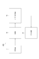
- FIG. 1 is a schematic configuration diagram showing the configuration of the molding system 100 according to the first embodiment.
- the molding system 100 includes a molding device 1, a laser machining device 70 (machining section), and a blasting device 50 (scale removing section).
- the molding device 1 is a device for molding a heated metal material with a molding die.
- a STAF molding apparatus that performs molding and quenching by supplying a fluid to a heated metal pipe material and bringing it into contact with the molding surface of a molding die is adopted. The detailed configuration of the molding apparatus 1 will be described with reference to FIG.
- FIG. 2 is a schematic view of the molding apparatus 1 used in the molding system 100 according to the present embodiment.
- the molding apparatus 1 is an apparatus for forming a metal pipe having a hollow shape by blow molding.
- the molding apparatus 1 is installed on a horizontal plane.
- the molding apparatus 1 includes a molding die 2, a drive mechanism 3, a holding unit 4, a heating unit 5, a fluid supply unit 6, a cooling unit 7, and a control unit 8.
- the metal pipe material 40 refers to a hollow article before the completion of molding by the molding apparatus 1.
- the metal pipe material 40 is a hardenable steel type pipe material.
- the direction in which the metal pipe material 40 extends at the time of molding may be referred to as "longitudinal direction”
- the direction orthogonal to the longitudinal direction may be referred to as "width direction”.
- the molding die 2 is a mold for molding a metal pipe 140 from a metal pipe material 40, and includes a lower mold 11 and an upper mold 12 facing each other in the vertical direction.
- the lower mold 11 and the upper mold 12 are made of steel blocks.
- Each of the lower mold 11 and the upper mold 12 is provided with a recess for accommodating the metal pipe material 40.
- the lower mold 11 and the upper mold 12 are in close contact with each other (mold closed state), and each recess forms a space having a target shape in which the metal pipe material is to be formed. Therefore, the surface of each recess becomes the molding surface of the molding die 2.
- the lower mold 11 is fixed to the base 13 via a die holder or the like.
- the upper mold 12 is fixed to the slide of the drive mechanism 3 via a die holder or the like.
- the drive mechanism 3 is a mechanism for moving at least one of the lower mold 11 and the upper mold 12.
- the drive mechanism 3 has a configuration in which only the upper mold 12 is moved.
- the drive mechanism 3 includes a slide 21 for moving the upper mold 12 so that the lower mold 11 and the upper mold 12 are aligned with each other, and a pull-back cylinder as an actuator for generating a force for pulling the slide 21 upward.
- a 22 is provided, a main cylinder 23 as a drive source for lowering and pressurizing the slide 21, and a drive source 24 for applying a driving force to the main cylinder 23.
- the holding portion 4 is a mechanism for holding the metal pipe material 40 arranged between the lower mold 11 and the upper mold 12.
- the holding portion 4 includes a lower electrode 26 and an upper electrode 27 that hold the metal pipe material 40 on one end side in the longitudinal direction of the molding die 2, and a metal pipe material on the other end side in the longitudinal direction of the molding die 2.
- a lower electrode 26 and an upper electrode 27 holding the 40 are provided.
- the lower electrodes 26 and the upper electrodes 27 on both sides in the longitudinal direction hold the metal pipe material 40 by sandwiching the vicinity of the end portion of the metal pipe material 40 from the vertical direction.
- Grooves having a shape corresponding to the outer peripheral surface of the metal pipe material 40 are formed on the upper surface of the lower electrode 26 and the lower surface of the upper electrode 27.
- the lower electrode 26 and the upper electrode 27 are provided with a drive mechanism (not shown), and can move independently in the vertical direction.
- the heating unit 5 heats the metal pipe material 40.
- the heating unit 5 is a mechanism for heating the metal pipe material 40 by energizing the metal pipe material 40.
- the metal pipe material 40 is separated from the lower mold 11 and the upper mold 12 between the lower mold 11 and the upper mold 12. 40 is heated.
- the heating unit 5 includes the lower electrodes 26 and the upper electrodes 27 on both sides in the longitudinal direction described above, and a power supply 28 for passing an electric current through the electrodes 26 and 27 to the metal pipe material 40.
- the heating unit may be arranged in the previous step of the molding apparatus 1 and heated externally.
- the fluid supply unit 6 is a mechanism for supplying a high-pressure fluid into the metal pipe material 40 held between the lower mold 11 and the upper mold 12.
- the fluid supply unit 6 supplies a high-pressure fluid to the metal pipe material 40 which has become hot due to being heated by the heating unit 5, and expands the metal pipe material 40.
- the fluid supply unit 6 is provided on both end sides of the molding die 2 in the longitudinal direction.
- the fluid supply unit 6 is a nozzle 31 that supplies fluid from the opening at the end of the metal pipe material 40 to the inside of the metal pipe material 40, and a drive that moves the nozzle 31 forward and backward with respect to the opening of the metal pipe material 40.
- a mechanism 32 and a supply source 33 for supplying a high-pressure fluid into the metal pipe material 40 via the nozzle 31 are provided.
- the drive mechanism 32 brings the nozzle 31 into close contact with the end of the metal pipe material 40 while ensuring the sealing property during fluid supply and exhaust, and separates the nozzle 31 from the end of the metal pipe material 40 at other times.
- the fluid supply unit 6 may supply a gas such as high-pressure air or an inert gas as the fluid. Further, the fluid supply unit 6 may be the same device including the heating unit 5 together with the holding unit 4 having a mechanism for moving the metal pipe material 40 in the vertical direction.
- the cooling unit 7 is a mechanism for cooling the molding die 2. By cooling the molding die 2, the cooling unit 7 can rapidly cool the metal pipe material 40 when the expanded metal pipe material 40 comes into contact with the molding surface of the molding die 2.
- the cooling unit 7 includes a flow path 36 formed inside the lower mold 11 and the upper mold 12, and a water circulation mechanism 37 that supplies and circulates cooling water to the flow path 36.
- the control unit 8 is a device that controls the entire molding device 1.
- the control unit 8 controls the drive mechanism 3, the holding unit 4, the heating unit 5, the fluid supply unit 6, and the cooling unit 7.
- the control unit 8 repeatedly performs an operation of molding the metal pipe material 40 with the molding die 2.
- control unit 8 controls, for example, the transfer timing from a transfer device such as a robot arm, and puts the metal pipe material 40 between the lower mold 11 and the upper mold 12 in the open state. Deploy. Alternatively, the control unit 8 may manually arrange the metal pipe material 40 between the lower mold 11 and the upper mold 12. Further, the control unit 8 supports the metal pipe material 40 with the lower electrodes 26 on both sides in the longitudinal direction, and then lowers the upper electrode 27 to sandwich the metal pipe material 40, such as an actuator of the holding unit 4. Control. Further, the control unit 8 controls the heating unit 5 to energize and heat the metal pipe material 40. As a result, an axial current flows through the metal pipe material 40, and the metal pipe material 40 itself generates heat due to Joule heat due to the electrical resistance of the metal pipe material 40 itself.
- the control unit 8 controls the drive mechanism 3 to lower the upper mold 12 and bring it closer to the lower mold 11 to close the molding mold 2.
- the control unit 8 controls the fluid supply unit 6 to seal the openings at both ends of the metal pipe material 40 with the nozzle 31 and supply the fluid.
- the metal pipe material 40 softened by heating expands and comes into contact with the molding surface of the molding die 2.
- the metal pipe material 40 is molded so as to follow the shape of the molding surface of the molding die 2.
- a part of the metal pipe material 40 is inserted into the gap between the lower mold 11 and the upper mold 12, and then the mold is further closed. The entrance portion is crushed to form a flange portion.
- the metal pipe material 40 comes into contact with the molding surface, the metal pipe material 40 is quenched by quenching with the molding die 2 cooled by the cooling unit 7.
- the control unit 8 closes the molding die 2 and supplies a fluid to the metal pipe material 40 by the fluid supply unit 6 to perform blow molding (primary blow). ..
- the control unit 8 forms the pipe portion 43 at the main cavity portion MC and causes the portion corresponding to the flange portion 44 to enter the sub-cavity portion SC.
- the control unit 8 forms the flange portion 44 by further closing the molding die 2 and further crushing the portion that has entered the subcavity portion SC.
- the control unit 8 raises the upper mold 12 and separates it from the metal pipe material 40 to open the mold. As a result, the molded product 41 is molded.
- the molded product 41 will be described with reference to FIG. 4 (a).
- the molded product 41 includes a molded main body 45 having a pipe portion 43 and a flange portion 44, held portions 46 on both ends in the longitudinal direction, and a gradual change portion 47 between the molded main body 45 and the held portion 46.
- the molding main body portion 45 is a portion that becomes a final product by being laser-processed.
- the pipe portion 43 is a hollow portion.
- the flange portion 44 is a plate-shaped portion that protrudes from the pipe portion 43 by crushing a part of the metal pipe material 40.
- the held portion 46 is a cylindrical portion held by the electrodes 26 and 27.
- the nozzle 31 is inserted into the held portion 46.
- the gradual change portion 47 is a transition portion that changes from the shape of the held portion 46 to the shape of the molding main body portion 45.
- the molded product 41 molded by the molding device 1 is supplied to the laser processing device 70.
- the molded product 41 may be sequentially supplied to the laser processing apparatus 70 from the one molded by the molding apparatus 1. Alternatively, after a certain number of molded products 41 have been accumulated at the accumulation location, they may be collectively supplied to the laser processing apparatus 70.
- the temperature of the molded products 41 can be lowered before laser processing due to the cooling effect of natural heat dissipation.
- the laser processing device 70 is a device that processes the molded product 41 removed from the molding die 2 with a laser.
- the laser processing apparatus 70 irradiates the molded product 41 with a laser to perform processing such as cutting, drilling, and forming a notch.
- FIG. 4 is a perspective view showing a state of laser processing by the laser processing device 70.
- the laser processing apparatus 70 includes an installation portion 71 and a laser head 72.
- the installation portion 71 is a portion for installing the molded product 41 at a position facing the laser head 72.
- the installation portion 71 has a support portion (not shown), and the support portion supports the molded product 41.
- the molded product 41 is installed in the installation portion 51 at a position and posture suitable for laser processing.
- the laser head 72 is a portion for processing the molded product 41 by irradiating the molded product 41 with a laser.
- the laser head 72 removes the gradual change portion 47 and the held portion 46 from the molding main body 45 by cutting the vicinity of both ends of the molding main body 45, as shown in FIG. 4 (b). Further, the laser head 72 forms a hole 49 at a predetermined position of the molding main body 45.
- the molded product 41 processed by the laser processing device 70 is supplied to the blasting device 50.
- the molded product 41 may be supplied to the blasting device 50 in order from the one processed by the laser processing device 70. Alternatively, after a certain number of molded products 41 have been accumulated at the accumulation location, they may be collectively supplied to the blasting apparatus 50.
- the blasting device 50 is a device that removes scale from the molded product 41 processed by the laser processing device 70.
- the scale is an oxide film formed on the surface of the metal pipe material 40 by heating the metal pipe material 40 in the molding apparatus 1.
- the blasting device 50 injects particles onto the surface of the molded product 41.
- the blasting device 50 removes the scale from the surface of the molded product 41 by the impact caused by the collision of the particles.
- FIG. 5A is a schematic view showing the blasting device 50 of the present embodiment.
- the blasting device 50 according to the present embodiment removes the scale on the outer peripheral surface of the molded product 41.
- the blasting device 50 does not inject particles onto the inner peripheral surface so as not to leave particles inside the molded product 41.
- the molded product 41 has a flange portion 44 by crushing a part of the metal pipe material 40. In the internal space of the molded product 41, particles tend to remain in such a flange portion 44. Therefore, the blasting device 50 injects particles only on the outer peripheral surface of the molded product 41.
- the blasting device 50 has an installation portion 51, a nozzle 52, and a shielding wall 53.
- the installation portion 51 is a portion for installing the molded product 41 at a position facing the nozzle 52.
- the installation portion 51 has a support portion (not shown), and the support portion supports the molded product 41.
- the molded product 41 is installed in the installation portion 51 at a position and posture suitable for blasting.
- the installation portion 51 is installed in a posture in which the molded product 41 is suspended and extends in the vertical direction.
- the nozzle 52 is a member that irradiates the molded product 41 with the particles 55.
- the particles for example, materials such as sand, plastic, dry ice, and iron pieces are adopted.
- the nozzle 52 is arranged around the molded product 41 installed in the installation portion 51.
- the nozzle 52 is arranged so that the injection port faces the outer peripheral surface of the molded product 41. As a result, the nozzle 52 can inject the particles 55 onto the outer peripheral surface of the molded product 41.
- the shielding wall 53 is a wall body that shields the particles 55.
- the shielding wall 53 is arranged so as to surround the installation portion 51 and the nozzle 52. As a result, the shielding wall 53 can prevent the particles 55 from scattering around the blasting device 50. That is, the shielding wall 53 can prevent the particles 55 from scattering to the molding apparatus 1 and the laser processing apparatus 70.
- a wall portion that partitions the space between the blasting device 50 and the laser processing device 70 may be provided.
- FIG. 6 is a process diagram showing a molding method according to the present embodiment.
- the molding method includes a molding step S10, a laser processing step S20 (processing step), and a blasting step S30 (scale removing step).
- a fluid is supplied to the heated metal pipe material 40, and the expanded metal pipe material 40 is brought into contact with the molding surface of the molding die 2 to mold the molded product 41.
- the molded product 41 is molded using the molding apparatus 1 shown in FIG.
- the laser processing step S20 is a step of processing the molded product 41 removed from the molding die 2.
- the blasting step S30 is a step of removing scale from the molded product 41 processed in the laser processing step S20.
- the blasting apparatus 50 shown in FIG. 5A performs a blasting process to remove the scale from the molded product 41.
- the molding apparatus 1 supplies a fluid to the heated metal pipe material 40 to expand it, and molds the heated metal pipe material 40 with the molding die 2. Therefore, scale is generated on the surface of the molded product 41.
- the laser processing apparatus 70 processes the molded product 41 removed from the molding die 2. Further, the blasting device 50 removes the scale from the molded product 41 processed by the laser processing device 70. In this way, the laser processing apparatus 70 processes the molded product 41 before removing the scale. In this case, the laser processing apparatus 70 can reduce the area to be scale-removed as compared with the molded product 41 immediately after molding. Therefore, the blasting device 50 can perform the scale removal process on the molded product 41 having a smaller area to be scale removed. As a result, the blasting device 50 can perform scale removal in a shorter time with a smaller device than that of performing the scale removing process on the molded product 41 immediately after molding. From the above, the efficiency of scale removal can be improved.
- the blasting device 50 when blasting is performed before processing by the laser processing device 70, the blasting device 50 will perform blasting up to non-product parts such as the gradual change portion 47 and the held portion 46.
- the molded product 41 When the molded product 41 is hung by the hanger method as shown in FIG. 5, it is necessary to set the height and width of the blasting device 50 in consideration of both ends of the molding main body 45 which are not products.
- the length of the blast hose 56 is a length that takes into consideration the portion that does not become a product.
- the blasting device 50 since the blasting is performed after cutting the non-product portion in advance, the blasting device 50 can be miniaturized and the blasting time is shortened by reducing the blasting range. can.
- the blasting device 50 may remove the scale from the molded product 41 by causing the particles to collide with the molded product 41.
- the blasting apparatus 50 can remove burrs, spatters, dross, etc. generated by the collision due to the collision of particles, and can flatten the surface.
- the molded product 41 there is a possibility that the periphery of the portion cut by the laser processing is tempered due to the influence of heat, or the surface is roughened by the laser processing.
- the blasting device 50 performs blasting after laser processing, it is possible to flatten the surface by blasting and aim for a shot peening effect by work hardening.
- the molded product 41 may be marked to indicate a reference position for laser processing. If blasting is performed before laser processing, the marking may become thin and difficult to read.
- the laser processing apparatus 70 since the laser processing apparatus 70 performs processing in the stage before blasting, the marking can be read in an easy-to-read state. Therefore, the processing accuracy of the laser processing apparatus 70 is improved.
- the molding system 200 includes a cooling unit 90 in front of the laser processing apparatus 70 for positively cooling the molded product 41 removed from the molding die 2.
- a cooling unit 90 a mechanism for supplying a cooling medium such as cold air, cold water, ice, and dry ice to the molded product 41 may be adopted.
- the cooling unit 90 may blow cold air onto the molded product 41 on the conveyor.
- the cooling unit 90 may blast dry ice.
- a device such as a refrigerator for accommodating the molded product 41 in a low temperature atmosphere may be adopted.
- the molded product 41 taken out from the molding die 2 is in a high temperature state. If processing is performed in the high temperature state, the processing accuracy will decrease due to the influence of cooling shrinkage when the temperature decreases. Therefore, it is necessary to lower the temperature of the molded product 41 before processing.
- the molding system 200 further includes a cooling unit 90 that positively cools the molded product 41 removed from the molding mold 2, and the laser processing device 70 further provides the molded product 41 cooled by the cooling unit 90. Process. By actively cooling the molded product 41 by the cooling unit 90, the time required for processing can be reduced as compared with the case where heat is naturally dissipated.
- the molding system 300 includes a first blasting device 50 arranged in front of the laser processing device 70 and a second blasting device 80 that removes scale from the molded product 41 processed by the laser processing device 70.
- the first blasting device 50 corresponds to the "cooling unit” in the claim
- the second blasting device 80 corresponds to the "scale removing unit” in the claim.
- the first blasting device 50 may inject dry ice as the particles 55. Even if the first blasting device 50 injects particles 55 other than dry ice, a cooling effect can be obtained due to the influence of blowing air, but a high cooling effect can be obtained by injecting dry ice.
- the second blasting device 80 injects particles 55 from the blast hose 56 onto the inner peripheral surface of the molded product 41.
- the blast hose 56 is inserted into the molded product 41 and ejects particles toward the inner peripheral surface inside the molded product 41.
- the blast hose 56 may inject dry ice as the particles 55.
- the dry ice collides with the inner peripheral surface of the molded product 41 as a solid and removes the scale, but it becomes a gas and disappears with the passage of time. Therefore, it is possible to prevent the particles 55 from remaining on the flange portion 44.
- the first blasting device 50 and the second blasting device 80 may be configured by a common device.
- the blast hose 56 of FIG. 5 (b) may be added to the blast device 50 of FIG. 5 (a).
- the blast hose 56 blasts the inner peripheral surface of the molded product 41. From the above, the number of devices of the molding system 200 can be reduced.
- the present invention is not limited to the above-described embodiment.
- the blasting device was exemplified as the scale removing unit.
- any device may be adopted as the scale removing unit as long as it can remove the scale.
- one that injects a fluid onto a molded product or removes scale by ultrasonic cleaning may be adopted.
- Such a scale removing portion also has a cooling effect.
- the processing unit is not limited to the laser processing apparatus, and an apparatus by another processing method may be adopted.
- the molding apparatus 1 is not limited to the configuration shown in FIG. 2, for example, the molding apparatus 1 may adopt the configuration shown in FIG. In the molding apparatus 1 shown in FIG. 9, the thermal expansion unit 150 as shown in FIG. 9 may be adopted.
- FIG. 10A is a schematic side view showing a heating expansion unit 150 in which the components of the holding unit 4, the heating unit 5, and the fluid supply unit 6 are unitized.
- FIG. 10B is a cross-sectional view showing a state when the nozzle 31 seals the metal pipe material 40.
- the thermal expansion unit 150 includes the above-mentioned lower electrode 26 and upper electrode 27, an electrode mounting unit 151 on which the respective electrodes 26 and 27 are mounted, and the above-mentioned nozzle 31 and drive mechanism 32. , Elevating unit 152 and unit base 153.
- the electrode mounting unit 151 includes an elevating frame 154 and electrode frames 156 and 157.
- the electrode frames 156 and 157 function as a part of a drive mechanism 60 that supports and moves the electrodes 26 and 27.
- the drive mechanism 32 drives the nozzle 31 and moves up and down together with the electrode mounting unit 151.
- the drive mechanism 32 includes a piston 61 that holds the nozzle 31 and a cylinder 62 that drives the piston.
- the elevating unit 152 includes an elevating frame base 64 attached to the upper surface of the unit base 153, and an elevating actuator 66 that imparts an elevating operation to the elevating frame 154 of the electrode mounting unit 151 by these elevating frame bases 64. ing.
- the elevating frame base 64 has guide portions 64a and 64b that guide the elevating operation of the elevating frame 154 with respect to the unit base 153.
- the elevating unit 152 functions as a part of the drive mechanism 60 of the holding unit 4.
- the thermal expansion unit 150 has a plurality of unit bases 153 having different inclination angles on the upper surface, and by exchanging these, the lower electrode 26 and the upper electrode 27, the nozzle 31, the electrode mounting unit 151, the drive mechanism 32, and the elevating mechanism 32 are moved up and down. It is possible to change and adjust the tilt angle of the unit 152 at once.
- the nozzle 31 is a cylindrical member into which the end of the metal pipe material 40 can be inserted.
- the nozzle 31 is supported by the drive mechanism 32 so that the center line of the nozzle 31 coincides with the reference line SL1.
- the inner diameter of the supply port 31a at the end of the nozzle 31 on the metal pipe material 40 side substantially matches the outer diameter of the metal pipe material 40 after expansion molding.
- the nozzle 31 supplies a high-pressure fluid to the metal pipe material 40 from the internal flow path 63.
- An example of a high-pressure fluid is gas or the like.
Landscapes
- Engineering & Computer Science (AREA)
- Mechanical Engineering (AREA)
- Physics & Mathematics (AREA)
- Fluid Mechanics (AREA)
- Optics & Photonics (AREA)
- Chemical & Material Sciences (AREA)
- Plasma & Fusion (AREA)
- Thermal Sciences (AREA)
- Crystallography & Structural Chemistry (AREA)
- Materials Engineering (AREA)
- Metallurgy (AREA)
- Organic Chemistry (AREA)
- Shaping Metal By Deep-Drawing, Or The Like (AREA)
Priority Applications (6)
| Application Number | Priority Date | Filing Date | Title |
|---|---|---|---|
| DE112021001520.6T DE112021001520T5 (de) | 2020-03-10 | 2021-03-05 | Formsystem und formverfahren |
| JP2022507155A JPWO2021182358A1 (https=) | 2020-03-10 | 2021-03-05 | |
| KR1020227015143A KR20220141781A (ko) | 2020-03-10 | 2021-03-05 | 성형시스템, 및 성형방법 |
| CN202411409731.1A CN119304034A (zh) | 2020-03-10 | 2021-03-05 | 成型系统及成型方法 |
| CN202180006516.5A CN114728384A (zh) | 2020-03-10 | 2021-03-05 | 成型系统及成型方法 |
| US17/847,370 US20220324007A1 (en) | 2020-03-10 | 2022-06-23 | Forming system and forming method |
Applications Claiming Priority (2)
| Application Number | Priority Date | Filing Date | Title |
|---|---|---|---|
| JP2020040979 | 2020-03-10 | ||
| JP2020-040979 | 2020-03-10 |
Related Child Applications (1)
| Application Number | Title | Priority Date | Filing Date |
|---|---|---|---|
| US17/847,370 Continuation US20220324007A1 (en) | 2020-03-10 | 2022-06-23 | Forming system and forming method |
Publications (1)
| Publication Number | Publication Date |
|---|---|
| WO2021182358A1 true WO2021182358A1 (ja) | 2021-09-16 |
Family
ID=77671657
Family Applications (1)
| Application Number | Title | Priority Date | Filing Date |
|---|---|---|---|
| PCT/JP2021/008833 Ceased WO2021182358A1 (ja) | 2020-03-10 | 2021-03-05 | 成形システム、及び成形方法 |
Country Status (6)
| Country | Link |
|---|---|
| US (1) | US20220324007A1 (https=) |
| JP (1) | JPWO2021182358A1 (https=) |
| KR (1) | KR20220141781A (https=) |
| CN (2) | CN119304034A (https=) |
| DE (1) | DE112021001520T5 (https=) |
| WO (1) | WO2021182358A1 (https=) |
Citations (3)
| Publication number | Priority date | Publication date | Assignee | Title |
|---|---|---|---|---|
| JP2013046916A (ja) * | 2011-08-29 | 2013-03-07 | Jfe Steel Corp | 熱延鋼板の熱間プレス成形方法 |
| JP2016022482A (ja) * | 2014-07-16 | 2016-02-08 | 住友重機械工業株式会社 | 成形装置 |
| JP2017536474A (ja) * | 2014-10-02 | 2017-12-07 | フォエスタルピネ スタール ゲーエムベーハー | 薄鋼板を中間冷却する方法 |
Family Cites Families (20)
| Publication number | Priority date | Publication date | Assignee | Title |
|---|---|---|---|---|
| JPS61115628A (ja) * | 1984-11-08 | 1986-06-03 | Sumitomo Metal Ind Ltd | α+β型チタン合金の非円形断面管製造方法 |
| JPH11245211A (ja) * | 1998-03-04 | 1999-09-14 | Sekisui Chem Co Ltd | 成形体製造用型と成形体の製造方法 |
| JP3571222B2 (ja) * | 1998-07-14 | 2004-09-29 | 古河スカイ株式会社 | 超塑性成形装置 |
| US7024897B2 (en) * | 1999-09-24 | 2006-04-11 | Hot Metal Gas Forming Intellectual Property, Inc. | Method of forming a tubular blank into a structural component and die therefor |
| US6694790B2 (en) * | 2002-04-17 | 2004-02-24 | General Motors Corporation | Mid plate process and equipment for the superplastic forming of parts from plural sheets |
| JP2009220141A (ja) | 2008-03-14 | 2009-10-01 | Marujun Co Ltd | パイプ製品の製造方法及び同製造装置 |
| KR101179763B1 (ko) * | 2009-05-07 | 2012-09-04 | 현대하이스코 주식회사 | 하이드로포밍을 이용한 다중복합강관 및 그 제조방법 |
| CN101811517B (zh) * | 2010-04-16 | 2013-03-27 | 无锡同捷汽车设计有限公司 | 一种内高压成形副车架及其成形方法 |
| RU2552819C1 (ru) * | 2011-05-23 | 2015-06-10 | Ниппон Стил Энд Сумитомо Метал Корпорейшн | Способ горячего прессования и форма для горячего прессового формования |
| DE202011051161U1 (de) * | 2011-08-31 | 2012-12-19 | Conntronic Prozess- Und Automatisierungstechnik Gmbh | Schneideinrichtung |
| JP6326224B2 (ja) * | 2013-12-09 | 2018-05-16 | 住友重機械工業株式会社 | 成形装置 |
| JP6400952B2 (ja) * | 2014-06-18 | 2018-10-03 | 住友重機械工業株式会社 | 成形システム及び成形方法 |
| JP6475437B2 (ja) * | 2014-08-05 | 2019-02-27 | 住友重機械工業株式会社 | 成形装置 |
| CA2993609C (en) * | 2015-08-28 | 2023-09-12 | Sumitomo Heavy Industries, Ltd. | Forming device |
| CN205271760U (zh) * | 2015-12-22 | 2016-06-01 | 郑州万达重工股份有限公司 | 一种喷砂环形悬挂装置 |
| CN107199270A (zh) * | 2017-03-28 | 2017-09-26 | 华侨大学 | 一种用于高强钢管材气体胀形的装置和方法 |
| CN107626767B (zh) * | 2017-10-11 | 2019-04-12 | 南京工程学院 | 一种马氏体钢复杂管型结构件的准流态快速成形方法 |
| CN108262693A (zh) * | 2017-12-29 | 2018-07-10 | 合肥盛强数控设备有限公司 | 一种金属件的抛光装置 |
| CN111788018A (zh) * | 2018-03-09 | 2020-10-16 | 住友重机械工业株式会社 | 成型装置及金属管 |
| CN109807756B (zh) * | 2019-01-23 | 2021-03-23 | 台州市凯亮眼镜股份有限公司 | 一种喷砂机 |
-
2021
- 2021-03-05 JP JP2022507155A patent/JPWO2021182358A1/ja active Pending
- 2021-03-05 CN CN202411409731.1A patent/CN119304034A/zh active Pending
- 2021-03-05 DE DE112021001520.6T patent/DE112021001520T5/de active Granted
- 2021-03-05 KR KR1020227015143A patent/KR20220141781A/ko active Pending
- 2021-03-05 CN CN202180006516.5A patent/CN114728384A/zh active Pending
- 2021-03-05 WO PCT/JP2021/008833 patent/WO2021182358A1/ja not_active Ceased
-
2022
- 2022-06-23 US US17/847,370 patent/US20220324007A1/en not_active Abandoned
Patent Citations (3)
| Publication number | Priority date | Publication date | Assignee | Title |
|---|---|---|---|---|
| JP2013046916A (ja) * | 2011-08-29 | 2013-03-07 | Jfe Steel Corp | 熱延鋼板の熱間プレス成形方法 |
| JP2016022482A (ja) * | 2014-07-16 | 2016-02-08 | 住友重機械工業株式会社 | 成形装置 |
| JP2017536474A (ja) * | 2014-10-02 | 2017-12-07 | フォエスタルピネ スタール ゲーエムベーハー | 薄鋼板を中間冷却する方法 |
Also Published As
| Publication number | Publication date |
|---|---|
| KR20220141781A (ko) | 2022-10-20 |
| CN114728384A (zh) | 2022-07-08 |
| DE112021001520T5 (de) | 2023-01-05 |
| US20220324007A1 (en) | 2022-10-13 |
| JPWO2021182358A1 (https=) | 2021-09-16 |
| CN119304034A (zh) | 2025-01-14 |
Similar Documents
| Publication | Publication Date | Title |
|---|---|---|
| KR101893930B1 (ko) | 성형장치 및 성형방법 | |
| US9855593B2 (en) | Molding apparatus, method for replacing components of molding apparatus, and replacement unit for molding apparatus | |
| JP6854035B1 (ja) | 熱処理装置 | |
| JP6417138B2 (ja) | 成形装置 | |
| JP6704982B2 (ja) | 成形装置 | |
| WO2021182358A1 (ja) | 成形システム、及び成形方法 | |
| WO2021182349A1 (ja) | 成形システム、及び成形方法 | |
| WO2021182359A1 (ja) | 成形システム、及び成形方法 | |
| US20240253103A1 (en) | Forming device and forming method | |
| JP2017171956A (ja) | 冷却処理設備及び冷却処理方法 | |
| CN114616061B (zh) | 成型装置及成型方法 | |
| CN118119460A (zh) | 成型装置 | |
| JP2022043699A (ja) | 成形型 | |
| JP4765919B2 (ja) | アルミニウム合金材の熱処理装置および熱処理方法 | |
| JP2021053688A (ja) | 成形装置及びブロー成形用の金属パイプ材料 | |
| WO2020195277A1 (ja) | 成形システム | |
| US20250222510A1 (en) | Forming system | |
| KR20260047179A (ko) | 성형장치 | |
| JP2021154338A (ja) | レーザー加工装置 | |
| CN121464006A (zh) | 成型装置、成型系统及金属管 | |
| JP6917093B1 (ja) | 生産システム | |
| CN113302010A (zh) | 消除热裂纹的方法 | |
| KR20130116117A (ko) | 열처리 기능을 갖는 미세입자 분사가공 장치 |
Legal Events
| Date | Code | Title | Description |
|---|---|---|---|
| 121 | Ep: the epo has been informed by wipo that ep was designated in this application |
Ref document number: 21767754 Country of ref document: EP Kind code of ref document: A1 |
|
| ENP | Entry into the national phase |
Ref document number: 2022507155 Country of ref document: JP Kind code of ref document: A |
|
| 122 | Ep: pct application non-entry in european phase |
Ref document number: 21767754 Country of ref document: EP Kind code of ref document: A1 |