WO2021182358A1 - 成形システム、及び成形方法 - Google Patents
成形システム、及び成形方法 Download PDFInfo
- Publication number
- WO2021182358A1 WO2021182358A1 PCT/JP2021/008833 JP2021008833W WO2021182358A1 WO 2021182358 A1 WO2021182358 A1 WO 2021182358A1 JP 2021008833 W JP2021008833 W JP 2021008833W WO 2021182358 A1 WO2021182358 A1 WO 2021182358A1
- Authority
- WO
- WIPO (PCT)
- Prior art keywords
- molding
- molded product
- metal pipe
- pipe material
- scale
- Prior art date
Links
Images


Classifications
-
- B—PERFORMING OPERATIONS; TRANSPORTING
- B21—MECHANICAL METAL-WORKING WITHOUT ESSENTIALLY REMOVING MATERIAL; PUNCHING METAL
- B21D—WORKING OR PROCESSING OF SHEET METAL OR METAL TUBES, RODS OR PROFILES WITHOUT ESSENTIALLY REMOVING MATERIAL; PUNCHING METAL
- B21D26/00—Shaping without cutting otherwise than using rigid devices or tools or yieldable or resilient pads, i.e. applying fluid pressure or magnetic forces
- B21D26/02—Shaping without cutting otherwise than using rigid devices or tools or yieldable or resilient pads, i.e. applying fluid pressure or magnetic forces by applying fluid pressure
- B21D26/033—Deforming tubular bodies
- B21D26/041—Means for controlling fluid parameters, e.g. pressure or temperature
-
- B—PERFORMING OPERATIONS; TRANSPORTING
- B23—MACHINE TOOLS; METAL-WORKING NOT OTHERWISE PROVIDED FOR
- B23P—METAL-WORKING NOT OTHERWISE PROVIDED FOR; COMBINED OPERATIONS; UNIVERSAL MACHINE TOOLS
- B23P23/00—Machines or arrangements of machines for performing specified combinations of different metal-working operations not covered by a single other subclass
- B23P23/04—Machines or arrangements of machines for performing specified combinations of different metal-working operations not covered by a single other subclass for both machining and other metal-working operations
-
- B—PERFORMING OPERATIONS; TRANSPORTING
- B21—MECHANICAL METAL-WORKING WITHOUT ESSENTIALLY REMOVING MATERIAL; PUNCHING METAL
- B21D—WORKING OR PROCESSING OF SHEET METAL OR METAL TUBES, RODS OR PROFILES WITHOUT ESSENTIALLY REMOVING MATERIAL; PUNCHING METAL
- B21D26/00—Shaping without cutting otherwise than using rigid devices or tools or yieldable or resilient pads, i.e. applying fluid pressure or magnetic forces
- B21D26/02—Shaping without cutting otherwise than using rigid devices or tools or yieldable or resilient pads, i.e. applying fluid pressure or magnetic forces by applying fluid pressure
- B21D26/033—Deforming tubular bodies
- B21D26/035—Deforming tubular bodies including an additional treatment performed by fluid pressure, e.g. perforating
-
- B—PERFORMING OPERATIONS; TRANSPORTING
- B21—MECHANICAL METAL-WORKING WITHOUT ESSENTIALLY REMOVING MATERIAL; PUNCHING METAL
- B21D—WORKING OR PROCESSING OF SHEET METAL OR METAL TUBES, RODS OR PROFILES WITHOUT ESSENTIALLY REMOVING MATERIAL; PUNCHING METAL
- B21D26/00—Shaping without cutting otherwise than using rigid devices or tools or yieldable or resilient pads, i.e. applying fluid pressure or magnetic forces
- B21D26/02—Shaping without cutting otherwise than using rigid devices or tools or yieldable or resilient pads, i.e. applying fluid pressure or magnetic forces by applying fluid pressure
- B21D26/033—Deforming tubular bodies
- B21D26/047—Mould construction
-
- B—PERFORMING OPERATIONS; TRANSPORTING
- B21—MECHANICAL METAL-WORKING WITHOUT ESSENTIALLY REMOVING MATERIAL; PUNCHING METAL
- B21D—WORKING OR PROCESSING OF SHEET METAL OR METAL TUBES, RODS OR PROFILES WITHOUT ESSENTIALLY REMOVING MATERIAL; PUNCHING METAL
- B21D37/00—Tools as parts of machines covered by this subclass
- B21D37/16—Heating or cooling
-
- B—PERFORMING OPERATIONS; TRANSPORTING
- B23—MACHINE TOOLS; METAL-WORKING NOT OTHERWISE PROVIDED FOR
- B23P—METAL-WORKING NOT OTHERWISE PROVIDED FOR; COMBINED OPERATIONS; UNIVERSAL MACHINE TOOLS
- B23P23/00—Machines or arrangements of machines for performing specified combinations of different metal-working operations not covered by a single other subclass
- B23P23/06—Metal-working plant comprising a number of associated machines or apparatus
-
- B—PERFORMING OPERATIONS; TRANSPORTING
- B24—GRINDING; POLISHING
- B24C—ABRASIVE OR RELATED BLASTING WITH PARTICULATE MATERIAL
- B24C1/00—Methods for use of abrasive blasting for producing particular effects; Use of auxiliary equipment in connection with such methods
-
- B—PERFORMING OPERATIONS; TRANSPORTING
- B24—GRINDING; POLISHING
- B24C—ABRASIVE OR RELATED BLASTING WITH PARTICULATE MATERIAL
- B24C1/00—Methods for use of abrasive blasting for producing particular effects; Use of auxiliary equipment in connection with such methods
- B24C1/08—Methods for use of abrasive blasting for producing particular effects; Use of auxiliary equipment in connection with such methods for polishing surfaces, e.g. smoothing a surface by making use of liquid-borne abrasives
- B24C1/086—Descaling; Removing coating films
-
- B—PERFORMING OPERATIONS; TRANSPORTING
- B24—GRINDING; POLISHING
- B24C—ABRASIVE OR RELATED BLASTING WITH PARTICULATE MATERIAL
- B24C11/00—Selection of abrasive materials or additives for abrasive blasts
-
- C—CHEMISTRY; METALLURGY
- C21—METALLURGY OF IRON
- C21D—MODIFYING THE PHYSICAL STRUCTURE OF FERROUS METALS; GENERAL DEVICES FOR HEAT TREATMENT OF FERROUS OR NON-FERROUS METALS OR ALLOYS; MAKING METAL MALLEABLE, e.g. BY DECARBURISATION OR TEMPERING
- C21D10/00—Modifying the physical properties by methods other than heat treatment or deformation
- C21D10/005—Modifying the physical properties by methods other than heat treatment or deformation by laser shock processing
-
- B—PERFORMING OPERATIONS; TRANSPORTING
- B23—MACHINE TOOLS; METAL-WORKING NOT OTHERWISE PROVIDED FOR
- B23P—METAL-WORKING NOT OTHERWISE PROVIDED FOR; COMBINED OPERATIONS; UNIVERSAL MACHINE TOOLS
- B23P15/00—Making specific metal objects by operations not covered by a single other subclass or a group in this subclass
-
- Y—GENERAL TAGGING OF NEW TECHNOLOGICAL DEVELOPMENTS; GENERAL TAGGING OF CROSS-SECTIONAL TECHNOLOGIES SPANNING OVER SEVERAL SECTIONS OF THE IPC; TECHNICAL SUBJECTS COVERED BY FORMER USPC CROSS-REFERENCE ART COLLECTIONS [XRACs] AND DIGESTS
- Y10—TECHNICAL SUBJECTS COVERED BY FORMER USPC
- Y10T—TECHNICAL SUBJECTS COVERED BY FORMER US CLASSIFICATION
- Y10T29/00—Metal working
- Y10T29/51—Plural diverse manufacturing apparatus including means for metal shaping or assembling
- Y10T29/5199—Work on tubes
Definitions
- the present invention relates to a molding system and a molding method.
- a molding system described in Patent Document 1 includes a molding apparatus.
- the molding apparatus includes a fluid supply unit that supplies a fluid to the heated metal pipe material, and a molding die that molds a molded product by bringing the expanded metal pipe material into contact with a molding surface.
- the molding system can bring the heated metal pipe material into contact with the molding die to perform molding and quenching at the same time.
- the heated metal pipe material is molded while quenching using a molding die, scale (oxide scale) is generated in the molded product.
- the molding system may include a scale remover to remove such scales from the part. It has been required to improve the efficiency of scale removal by this scale removing unit.
- the present invention has been made to solve such a problem, and an object of the present invention is to provide a molding system and a molding method capable of improving the efficiency of scale removal.
- the molding system according to the present invention includes a molding apparatus including a fluid supply unit that supplies a fluid to a heated metal pipe material and a molding die that molds a molded product by bringing the expanded metal pipe material into contact with a molding surface.
- a molding system including a processing unit for processing a molded product removed from a molding die and a scale removing unit for removing scale from a molded product processed by the processing unit.
- the molding device supplies a fluid to the heated metal pipe material to expand it and mold it with a molding die. Therefore, scale is generated on the surface of the molded product.
- the processing unit processes the molded product removed from the molding die.
- the scale removing section removes the scale from the molded product processed by the processed section. In this way, the processed part processes the molded product before removing the scale.
- the processed portion can reduce the area to be scale-removed as compared with the molded product immediately after molding. Therefore, the scale removing unit can perform the scale removing process on the molded product having a smaller area to be scale removed. As a result, the scale removing unit can remove the scale in a short time with a small device, rather than performing the scale removing process on the molded product immediately after molding. From the above, the efficiency of scale removal can be improved.
- the scale removing unit may remove the scale from the molded product by colliding the particles with the molded product.
- the scale removing portion can remove burrs, spatters, dross, etc. generated by the collision due to the collision of particles, and can flatten the surface.
- the molding system further includes a cooling unit that positively cools the molded product removed from the molding mold, and the processing unit may process the molded product cooled by the cooling unit.
- the processing unit may process the molded product cooled by the cooling unit. For example, when the processed portion processes using a laser, it is necessary to lower the temperature of the molded product to room temperature. By actively cooling the molded product by the cooling unit, the time required for processing can be reduced as compared with the case where heat is dissipated naturally.
- the molding method includes a molding step of supplying a fluid to a heated metal pipe material and bringing the expanded metal pipe material into contact with the molding surface of the molding die to form a molded product, and the molding process is removed from the molding die. It includes a processing step of processing a molded product and a scale removing step of removing scale from the molded product processed in the processing step.
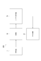
- FIG. 1 is a schematic configuration diagram showing the configuration of the molding system 100 according to the first embodiment.
- the molding system 100 includes a molding device 1, a laser machining device 70 (machining section), and a blasting device 50 (scale removing section).
- the molding device 1 is a device for molding a heated metal material with a molding die.
- a STAF molding apparatus that performs molding and quenching by supplying a fluid to a heated metal pipe material and bringing it into contact with the molding surface of a molding die is adopted. The detailed configuration of the molding apparatus 1 will be described with reference to FIG.
- FIG. 2 is a schematic view of the molding apparatus 1 used in the molding system 100 according to the present embodiment.
- the molding apparatus 1 is an apparatus for forming a metal pipe having a hollow shape by blow molding.
- the molding apparatus 1 is installed on a horizontal plane.
- the molding apparatus 1 includes a molding die 2, a drive mechanism 3, a holding unit 4, a heating unit 5, a fluid supply unit 6, a cooling unit 7, and a control unit 8.
- the metal pipe material 40 refers to a hollow article before the completion of molding by the molding apparatus 1.
- the metal pipe material 40 is a hardenable steel type pipe material.
- the direction in which the metal pipe material 40 extends at the time of molding may be referred to as "longitudinal direction”
- the direction orthogonal to the longitudinal direction may be referred to as "width direction”.
- the molding die 2 is a mold for molding a metal pipe 140 from a metal pipe material 40, and includes a lower mold 11 and an upper mold 12 facing each other in the vertical direction.
- the lower mold 11 and the upper mold 12 are made of steel blocks.
- Each of the lower mold 11 and the upper mold 12 is provided with a recess for accommodating the metal pipe material 40.
- the lower mold 11 and the upper mold 12 are in close contact with each other (mold closed state), and each recess forms a space having a target shape in which the metal pipe material is to be formed. Therefore, the surface of each recess becomes the molding surface of the molding die 2.
- the lower mold 11 is fixed to the base 13 via a die holder or the like.
- the upper mold 12 is fixed to the slide of the drive mechanism 3 via a die holder or the like.
- the drive mechanism 3 is a mechanism for moving at least one of the lower mold 11 and the upper mold 12.
- the drive mechanism 3 has a configuration in which only the upper mold 12 is moved.
- the drive mechanism 3 includes a slide 21 for moving the upper mold 12 so that the lower mold 11 and the upper mold 12 are aligned with each other, and a pull-back cylinder as an actuator for generating a force for pulling the slide 21 upward.
- a 22 is provided, a main cylinder 23 as a drive source for lowering and pressurizing the slide 21, and a drive source 24 for applying a driving force to the main cylinder 23.
- the holding portion 4 is a mechanism for holding the metal pipe material 40 arranged between the lower mold 11 and the upper mold 12.
- the holding portion 4 includes a lower electrode 26 and an upper electrode 27 that hold the metal pipe material 40 on one end side in the longitudinal direction of the molding die 2, and a metal pipe material on the other end side in the longitudinal direction of the molding die 2.
- a lower electrode 26 and an upper electrode 27 holding the 40 are provided.
- the lower electrodes 26 and the upper electrodes 27 on both sides in the longitudinal direction hold the metal pipe material 40 by sandwiching the vicinity of the end portion of the metal pipe material 40 from the vertical direction.
- Grooves having a shape corresponding to the outer peripheral surface of the metal pipe material 40 are formed on the upper surface of the lower electrode 26 and the lower surface of the upper electrode 27.
- the lower electrode 26 and the upper electrode 27 are provided with a drive mechanism (not shown), and can move independently in the vertical direction.
- the heating unit 5 heats the metal pipe material 40.
- the heating unit 5 is a mechanism for heating the metal pipe material 40 by energizing the metal pipe material 40.
- the metal pipe material 40 is separated from the lower mold 11 and the upper mold 12 between the lower mold 11 and the upper mold 12. 40 is heated.
- the heating unit 5 includes the lower electrodes 26 and the upper electrodes 27 on both sides in the longitudinal direction described above, and a power supply 28 for passing an electric current through the electrodes 26 and 27 to the metal pipe material 40.
- the heating unit may be arranged in the previous step of the molding apparatus 1 and heated externally.
- the fluid supply unit 6 is a mechanism for supplying a high-pressure fluid into the metal pipe material 40 held between the lower mold 11 and the upper mold 12.
- the fluid supply unit 6 supplies a high-pressure fluid to the metal pipe material 40 which has become hot due to being heated by the heating unit 5, and expands the metal pipe material 40.
- the fluid supply unit 6 is provided on both end sides of the molding die 2 in the longitudinal direction.
- the fluid supply unit 6 is a nozzle 31 that supplies fluid from the opening at the end of the metal pipe material 40 to the inside of the metal pipe material 40, and a drive that moves the nozzle 31 forward and backward with respect to the opening of the metal pipe material 40.
- a mechanism 32 and a supply source 33 for supplying a high-pressure fluid into the metal pipe material 40 via the nozzle 31 are provided.
- the drive mechanism 32 brings the nozzle 31 into close contact with the end of the metal pipe material 40 while ensuring the sealing property during fluid supply and exhaust, and separates the nozzle 31 from the end of the metal pipe material 40 at other times.
- the fluid supply unit 6 may supply a gas such as high-pressure air or an inert gas as the fluid. Further, the fluid supply unit 6 may be the same device including the heating unit 5 together with the holding unit 4 having a mechanism for moving the metal pipe material 40 in the vertical direction.
- the cooling unit 7 is a mechanism for cooling the molding die 2. By cooling the molding die 2, the cooling unit 7 can rapidly cool the metal pipe material 40 when the expanded metal pipe material 40 comes into contact with the molding surface of the molding die 2.
- the cooling unit 7 includes a flow path 36 formed inside the lower mold 11 and the upper mold 12, and a water circulation mechanism 37 that supplies and circulates cooling water to the flow path 36.
- the control unit 8 is a device that controls the entire molding device 1.
- the control unit 8 controls the drive mechanism 3, the holding unit 4, the heating unit 5, the fluid supply unit 6, and the cooling unit 7.
- the control unit 8 repeatedly performs an operation of molding the metal pipe material 40 with the molding die 2.
- control unit 8 controls, for example, the transfer timing from a transfer device such as a robot arm, and puts the metal pipe material 40 between the lower mold 11 and the upper mold 12 in the open state. Deploy. Alternatively, the control unit 8 may manually arrange the metal pipe material 40 between the lower mold 11 and the upper mold 12. Further, the control unit 8 supports the metal pipe material 40 with the lower electrodes 26 on both sides in the longitudinal direction, and then lowers the upper electrode 27 to sandwich the metal pipe material 40, such as an actuator of the holding unit 4. Control. Further, the control unit 8 controls the heating unit 5 to energize and heat the metal pipe material 40. As a result, an axial current flows through the metal pipe material 40, and the metal pipe material 40 itself generates heat due to Joule heat due to the electrical resistance of the metal pipe material 40 itself.
- the control unit 8 controls the drive mechanism 3 to lower the upper mold 12 and bring it closer to the lower mold 11 to close the molding mold 2.
- the control unit 8 controls the fluid supply unit 6 to seal the openings at both ends of the metal pipe material 40 with the nozzle 31 and supply the fluid.
- the metal pipe material 40 softened by heating expands and comes into contact with the molding surface of the molding die 2.
- the metal pipe material 40 is molded so as to follow the shape of the molding surface of the molding die 2.
- a part of the metal pipe material 40 is inserted into the gap between the lower mold 11 and the upper mold 12, and then the mold is further closed. The entrance portion is crushed to form a flange portion.
- the metal pipe material 40 comes into contact with the molding surface, the metal pipe material 40 is quenched by quenching with the molding die 2 cooled by the cooling unit 7.
- the control unit 8 closes the molding die 2 and supplies a fluid to the metal pipe material 40 by the fluid supply unit 6 to perform blow molding (primary blow). ..
- the control unit 8 forms the pipe portion 43 at the main cavity portion MC and causes the portion corresponding to the flange portion 44 to enter the sub-cavity portion SC.
- the control unit 8 forms the flange portion 44 by further closing the molding die 2 and further crushing the portion that has entered the subcavity portion SC.
- the control unit 8 raises the upper mold 12 and separates it from the metal pipe material 40 to open the mold. As a result, the molded product 41 is molded.
- the molded product 41 will be described with reference to FIG. 4 (a).
- the molded product 41 includes a molded main body 45 having a pipe portion 43 and a flange portion 44, held portions 46 on both ends in the longitudinal direction, and a gradual change portion 47 between the molded main body 45 and the held portion 46.
- the molding main body portion 45 is a portion that becomes a final product by being laser-processed.
- the pipe portion 43 is a hollow portion.
- the flange portion 44 is a plate-shaped portion that protrudes from the pipe portion 43 by crushing a part of the metal pipe material 40.
- the held portion 46 is a cylindrical portion held by the electrodes 26 and 27.
- the nozzle 31 is inserted into the held portion 46.
- the gradual change portion 47 is a transition portion that changes from the shape of the held portion 46 to the shape of the molding main body portion 45.
- the molded product 41 molded by the molding device 1 is supplied to the laser processing device 70.
- the molded product 41 may be sequentially supplied to the laser processing apparatus 70 from the one molded by the molding apparatus 1. Alternatively, after a certain number of molded products 41 have been accumulated at the accumulation location, they may be collectively supplied to the laser processing apparatus 70.
- the temperature of the molded products 41 can be lowered before laser processing due to the cooling effect of natural heat dissipation.
- the laser processing device 70 is a device that processes the molded product 41 removed from the molding die 2 with a laser.
- the laser processing apparatus 70 irradiates the molded product 41 with a laser to perform processing such as cutting, drilling, and forming a notch.
- FIG. 4 is a perspective view showing a state of laser processing by the laser processing device 70.
- the laser processing apparatus 70 includes an installation portion 71 and a laser head 72.
- the installation portion 71 is a portion for installing the molded product 41 at a position facing the laser head 72.
- the installation portion 71 has a support portion (not shown), and the support portion supports the molded product 41.
- the molded product 41 is installed in the installation portion 51 at a position and posture suitable for laser processing.
- the laser head 72 is a portion for processing the molded product 41 by irradiating the molded product 41 with a laser.
- the laser head 72 removes the gradual change portion 47 and the held portion 46 from the molding main body 45 by cutting the vicinity of both ends of the molding main body 45, as shown in FIG. 4 (b). Further, the laser head 72 forms a hole 49 at a predetermined position of the molding main body 45.
- the molded product 41 processed by the laser processing device 70 is supplied to the blasting device 50.
- the molded product 41 may be supplied to the blasting device 50 in order from the one processed by the laser processing device 70. Alternatively, after a certain number of molded products 41 have been accumulated at the accumulation location, they may be collectively supplied to the blasting apparatus 50.
- the blasting device 50 is a device that removes scale from the molded product 41 processed by the laser processing device 70.
- the scale is an oxide film formed on the surface of the metal pipe material 40 by heating the metal pipe material 40 in the molding apparatus 1.
- the blasting device 50 injects particles onto the surface of the molded product 41.
- the blasting device 50 removes the scale from the surface of the molded product 41 by the impact caused by the collision of the particles.
- FIG. 5A is a schematic view showing the blasting device 50 of the present embodiment.
- the blasting device 50 according to the present embodiment removes the scale on the outer peripheral surface of the molded product 41.
- the blasting device 50 does not inject particles onto the inner peripheral surface so as not to leave particles inside the molded product 41.
- the molded product 41 has a flange portion 44 by crushing a part of the metal pipe material 40. In the internal space of the molded product 41, particles tend to remain in such a flange portion 44. Therefore, the blasting device 50 injects particles only on the outer peripheral surface of the molded product 41.
- the blasting device 50 has an installation portion 51, a nozzle 52, and a shielding wall 53.
- the installation portion 51 is a portion for installing the molded product 41 at a position facing the nozzle 52.
- the installation portion 51 has a support portion (not shown), and the support portion supports the molded product 41.
- the molded product 41 is installed in the installation portion 51 at a position and posture suitable for blasting.
- the installation portion 51 is installed in a posture in which the molded product 41 is suspended and extends in the vertical direction.
- the nozzle 52 is a member that irradiates the molded product 41 with the particles 55.
- the particles for example, materials such as sand, plastic, dry ice, and iron pieces are adopted.
- the nozzle 52 is arranged around the molded product 41 installed in the installation portion 51.
- the nozzle 52 is arranged so that the injection port faces the outer peripheral surface of the molded product 41. As a result, the nozzle 52 can inject the particles 55 onto the outer peripheral surface of the molded product 41.
- the shielding wall 53 is a wall body that shields the particles 55.
- the shielding wall 53 is arranged so as to surround the installation portion 51 and the nozzle 52. As a result, the shielding wall 53 can prevent the particles 55 from scattering around the blasting device 50. That is, the shielding wall 53 can prevent the particles 55 from scattering to the molding apparatus 1 and the laser processing apparatus 70.
- a wall portion that partitions the space between the blasting device 50 and the laser processing device 70 may be provided.
- FIG. 6 is a process diagram showing a molding method according to the present embodiment.
- the molding method includes a molding step S10, a laser processing step S20 (processing step), and a blasting step S30 (scale removing step).
- a fluid is supplied to the heated metal pipe material 40, and the expanded metal pipe material 40 is brought into contact with the molding surface of the molding die 2 to mold the molded product 41.
- the molded product 41 is molded using the molding apparatus 1 shown in FIG.
- the laser processing step S20 is a step of processing the molded product 41 removed from the molding die 2.
- the blasting step S30 is a step of removing scale from the molded product 41 processed in the laser processing step S20.
- the blasting apparatus 50 shown in FIG. 5A performs a blasting process to remove the scale from the molded product 41.
- the molding apparatus 1 supplies a fluid to the heated metal pipe material 40 to expand it, and molds the heated metal pipe material 40 with the molding die 2. Therefore, scale is generated on the surface of the molded product 41.
- the laser processing apparatus 70 processes the molded product 41 removed from the molding die 2. Further, the blasting device 50 removes the scale from the molded product 41 processed by the laser processing device 70. In this way, the laser processing apparatus 70 processes the molded product 41 before removing the scale. In this case, the laser processing apparatus 70 can reduce the area to be scale-removed as compared with the molded product 41 immediately after molding. Therefore, the blasting device 50 can perform the scale removal process on the molded product 41 having a smaller area to be scale removed. As a result, the blasting device 50 can perform scale removal in a shorter time with a smaller device than that of performing the scale removing process on the molded product 41 immediately after molding. From the above, the efficiency of scale removal can be improved.
- the blasting device 50 when blasting is performed before processing by the laser processing device 70, the blasting device 50 will perform blasting up to non-product parts such as the gradual change portion 47 and the held portion 46.
- the molded product 41 When the molded product 41 is hung by the hanger method as shown in FIG. 5, it is necessary to set the height and width of the blasting device 50 in consideration of both ends of the molding main body 45 which are not products.
- the length of the blast hose 56 is a length that takes into consideration the portion that does not become a product.
- the blasting device 50 since the blasting is performed after cutting the non-product portion in advance, the blasting device 50 can be miniaturized and the blasting time is shortened by reducing the blasting range. can.
- the blasting device 50 may remove the scale from the molded product 41 by causing the particles to collide with the molded product 41.
- the blasting apparatus 50 can remove burrs, spatters, dross, etc. generated by the collision due to the collision of particles, and can flatten the surface.
- the molded product 41 there is a possibility that the periphery of the portion cut by the laser processing is tempered due to the influence of heat, or the surface is roughened by the laser processing.
- the blasting device 50 performs blasting after laser processing, it is possible to flatten the surface by blasting and aim for a shot peening effect by work hardening.
- the molded product 41 may be marked to indicate a reference position for laser processing. If blasting is performed before laser processing, the marking may become thin and difficult to read.
- the laser processing apparatus 70 since the laser processing apparatus 70 performs processing in the stage before blasting, the marking can be read in an easy-to-read state. Therefore, the processing accuracy of the laser processing apparatus 70 is improved.
- the molding system 200 includes a cooling unit 90 in front of the laser processing apparatus 70 for positively cooling the molded product 41 removed from the molding die 2.
- a cooling unit 90 a mechanism for supplying a cooling medium such as cold air, cold water, ice, and dry ice to the molded product 41 may be adopted.
- the cooling unit 90 may blow cold air onto the molded product 41 on the conveyor.
- the cooling unit 90 may blast dry ice.
- a device such as a refrigerator for accommodating the molded product 41 in a low temperature atmosphere may be adopted.
- the molded product 41 taken out from the molding die 2 is in a high temperature state. If processing is performed in the high temperature state, the processing accuracy will decrease due to the influence of cooling shrinkage when the temperature decreases. Therefore, it is necessary to lower the temperature of the molded product 41 before processing.
- the molding system 200 further includes a cooling unit 90 that positively cools the molded product 41 removed from the molding mold 2, and the laser processing device 70 further provides the molded product 41 cooled by the cooling unit 90. Process. By actively cooling the molded product 41 by the cooling unit 90, the time required for processing can be reduced as compared with the case where heat is naturally dissipated.
- the molding system 300 includes a first blasting device 50 arranged in front of the laser processing device 70 and a second blasting device 80 that removes scale from the molded product 41 processed by the laser processing device 70.
- the first blasting device 50 corresponds to the "cooling unit” in the claim
- the second blasting device 80 corresponds to the "scale removing unit” in the claim.
- the first blasting device 50 may inject dry ice as the particles 55. Even if the first blasting device 50 injects particles 55 other than dry ice, a cooling effect can be obtained due to the influence of blowing air, but a high cooling effect can be obtained by injecting dry ice.
- the second blasting device 80 injects particles 55 from the blast hose 56 onto the inner peripheral surface of the molded product 41.
- the blast hose 56 is inserted into the molded product 41 and ejects particles toward the inner peripheral surface inside the molded product 41.
- the blast hose 56 may inject dry ice as the particles 55.
- the dry ice collides with the inner peripheral surface of the molded product 41 as a solid and removes the scale, but it becomes a gas and disappears with the passage of time. Therefore, it is possible to prevent the particles 55 from remaining on the flange portion 44.
- the first blasting device 50 and the second blasting device 80 may be configured by a common device.
- the blast hose 56 of FIG. 5 (b) may be added to the blast device 50 of FIG. 5 (a).
- the blast hose 56 blasts the inner peripheral surface of the molded product 41. From the above, the number of devices of the molding system 200 can be reduced.
- the present invention is not limited to the above-described embodiment.
- the blasting device was exemplified as the scale removing unit.
- any device may be adopted as the scale removing unit as long as it can remove the scale.
- one that injects a fluid onto a molded product or removes scale by ultrasonic cleaning may be adopted.
- Such a scale removing portion also has a cooling effect.
- the processing unit is not limited to the laser processing apparatus, and an apparatus by another processing method may be adopted.
- the molding apparatus 1 is not limited to the configuration shown in FIG. 2, for example, the molding apparatus 1 may adopt the configuration shown in FIG. In the molding apparatus 1 shown in FIG. 9, the thermal expansion unit 150 as shown in FIG. 9 may be adopted.
- FIG. 10A is a schematic side view showing a heating expansion unit 150 in which the components of the holding unit 4, the heating unit 5, and the fluid supply unit 6 are unitized.
- FIG. 10B is a cross-sectional view showing a state when the nozzle 31 seals the metal pipe material 40.
- the thermal expansion unit 150 includes the above-mentioned lower electrode 26 and upper electrode 27, an electrode mounting unit 151 on which the respective electrodes 26 and 27 are mounted, and the above-mentioned nozzle 31 and drive mechanism 32. , Elevating unit 152 and unit base 153.
- the electrode mounting unit 151 includes an elevating frame 154 and electrode frames 156 and 157.
- the electrode frames 156 and 157 function as a part of a drive mechanism 60 that supports and moves the electrodes 26 and 27.
- the drive mechanism 32 drives the nozzle 31 and moves up and down together with the electrode mounting unit 151.
- the drive mechanism 32 includes a piston 61 that holds the nozzle 31 and a cylinder 62 that drives the piston.
- the elevating unit 152 includes an elevating frame base 64 attached to the upper surface of the unit base 153, and an elevating actuator 66 that imparts an elevating operation to the elevating frame 154 of the electrode mounting unit 151 by these elevating frame bases 64. ing.
- the elevating frame base 64 has guide portions 64a and 64b that guide the elevating operation of the elevating frame 154 with respect to the unit base 153.
- the elevating unit 152 functions as a part of the drive mechanism 60 of the holding unit 4.
- the thermal expansion unit 150 has a plurality of unit bases 153 having different inclination angles on the upper surface, and by exchanging these, the lower electrode 26 and the upper electrode 27, the nozzle 31, the electrode mounting unit 151, the drive mechanism 32, and the elevating mechanism 32 are moved up and down. It is possible to change and adjust the tilt angle of the unit 152 at once.
- the nozzle 31 is a cylindrical member into which the end of the metal pipe material 40 can be inserted.
- the nozzle 31 is supported by the drive mechanism 32 so that the center line of the nozzle 31 coincides with the reference line SL1.
- the inner diameter of the supply port 31a at the end of the nozzle 31 on the metal pipe material 40 side substantially matches the outer diameter of the metal pipe material 40 after expansion molding.
- the nozzle 31 supplies a high-pressure fluid to the metal pipe material 40 from the internal flow path 63.
- An example of a high-pressure fluid is gas or the like.
Landscapes
- Engineering & Computer Science (AREA)
- Mechanical Engineering (AREA)
- Physics & Mathematics (AREA)
- Fluid Mechanics (AREA)
- Optics & Photonics (AREA)
- Chemical & Material Sciences (AREA)
- Thermal Sciences (AREA)
- Crystallography & Structural Chemistry (AREA)
- Materials Engineering (AREA)
- Metallurgy (AREA)
- Organic Chemistry (AREA)
- Shaping Metal By Deep-Drawing, Or The Like (AREA)
Abstract
成形システムは、加熱された金属パイプ材料に流体を供給する流体供給部、及び膨張した金属パイプ材料を成形面に接触させることで成形品を成形する成形金型を備える成形装置と、成形金型から取り外された成形品を加工する加工部と、加工部で加工された成形品からスケールを除去するスケール除去部と、を備える成形システム。
Description
本発明は、成形システム、及び成形方法に関する。
従来、成形システムとして、特許文献1に記載されたものが知られている。この成形システムは、成形装置を備える。成形装置は、加熱された金属パイプ材料に流体を供給する流体供給部と、膨張した金属パイプ材料を成形面に接触させることで成形品を成形する成形金型と、を有する。このように、成形システムは、加熱された金属パイプ材料を成形金型と接触させて成形を行うと同時に焼き入れを行うことができる。
ここで、上述の特許文献1に記載の成形システムは、加熱された金属パイプ材料を成形金型を用いて焼き入れしながら成形するため、成形品にスケール(酸化スケール)が発生する。成形システムは、このようなスケールを成形品から除去するためにスケール除去部を備える場合がある。このスケール除去部によるスケール除去の効率を向上させることが求められていた。
本発明は、このような課題を解決するためになされたものであり、スケール除去の効率を向上させることができる成形システム及び成形方法を提供することを目的とする。
本発明に係る成形システムは、加熱された金属パイプ材料に流体を供給する流体供給部、及び膨張した金属パイプ材料を成形面に接触させることで成形品を成形する成形金型を備える成形装置と、成形金型から取り外された成形品を加工する加工部と、加工部で加工された成形品からスケールを除去するスケール除去部と、を備える成形システム。
成形システムにおいて、成形装置は、加熱された金属パイプ材料に流体を供給して膨張させて成形金型で成形を行う。従って、成形品の表面にはスケールが発生する。これに対し、加工部は、成形金型から取り外された成形品を加工する。また、スケール除去部は、加工部で加工された成形品からスケールを除去する。このように、加工部は、スケールを除去する前段階で、成形品を加工する。この場合、加工部は、成形直後の成形品よりも、スケール除去の対象となる面積を減らすことができる。従って、スケール除去部は、スケール除去の対象となる面積が小さくなった成形品に対して、スケール除去の処理を行うことができる。これにより、スケール除去部は、成形直後の成形品に対してスケール除去の処理を行うよりも、小さい装置にて短時間でスケール除去を行うことができる。以上より、スケール除去の効率を向上できる。
スケール除去部は、成形品に粒子を衝突させることにより、スケールを成形品から除去してよい。この場合、スケール除去部は、粒子の衝突により、加工に伴って生じたバリ、スパッタ、ドロス等の除去や、面の平坦化などを行うことができる。
成形システムは、成形金型から取り外された成形品を積極的に冷却する冷却部を更に備え、加工部は、冷却部で冷却された成形品を加工してよい。例えば、加工部がレーザーを用いて加工を行う場合、成形品の温度を室温まで下げておく必要がある。冷却部が積極的に成形品を冷却することで、自然に放熱を行う場合に比して、加工までに要する時間を低減できる。
成形方法は、加熱された金属パイプ材料に流体を供給し、膨張した前記金属パイプ材料を成形金型の成形面に接触させることで成形品を成形する成形工程と、成形金型から取り外された成形品を加工する加工工程と、加工工程で加工された成形品からスケールを除去するスケール除去工程と、を備える。
この成形方法によれば、上述の成形システムと同様な作用・効果を得ることができる。
本発明によれば、スケール除去の効率を向上させることができる成形システム及び成形方法を提供できる。
以下、本発明の好適な実施形態について図面を参照しながら説明する。なお、各図において同一部分又は相当部分には同一符号を付し、重複する説明は省略する。
[第1実施形態]
図1は、第1実施形態に係る成形システム100の構成を示す概略構成図である。図1に示すように、成形システム100は、成形装置1と、レーザー加工装置70(加工部)と、ブラスト装置50(スケール除去部)と、を備える。
図1は、第1実施形態に係る成形システム100の構成を示す概略構成図である。図1に示すように、成形システム100は、成形装置1と、レーザー加工装置70(加工部)と、ブラスト装置50(スケール除去部)と、を備える。
成形装置1は、加熱された金属材料を成形金型で成形する装置である。本実施形態では、成形装置1として、加熱された金属パイプ材料に流体を供給して成形金型の成形面に接触させることで成形及び焼き入れを行うSTAF成形装置が採用されている。この成形装置1の詳細な構成について、図2を参照して説明する。
図2は、本実施形態に係る成形システム100で用いられている成形装置1の概略図である。図2に示すように、成形装置1は、ブロー成形によって中空形状を有する金属パイプを成形する装置である。本実施形態では、成形装置1は、水平面上に設置される。成形装置1は、成形金型2と、駆動機構3と、保持部4と、加熱部5と、流体供給部6と、冷却部7と、制御部8と、を備える。なお、本明細書において、金属パイプ材料40(金属材料)は、成形装置1での成形完了前の中空物品を指す。金属パイプ材料40は、焼入れ可能な鋼種のパイプ材料である。また、水平方向のうち、成形時において金属パイプ材料40が延びる方向を「長手方向」と称し、長手方向と直交する方向を「幅方向」と称する場合がある。
成形金型2は、金属パイプ材料40から金属パイプ140を成形する型であり、上下方向に互いに対向する下側の金型11及び上側の金型12を備える。下側の金型11及び上側の金型12は、鋼鉄製ブロックで構成される。下側の金型11及び上側の金型12のそれぞれには、金属パイプ材料40が収容される凹部が設けられる。下側の金型11と上側の金型12は、互いに密接した状態(型閉状態)で、各々の凹部が金属パイプ材料を成形すべき目標形状の空間を形成する。従って、各々の凹部の表面が成形金型2の成形面となる。下側の金型11は、ダイホルダ等を介して基台13に固定される。上側の金型12は、ダイホルダ等を介して駆動機構3のスライドに固定される。
駆動機構3は、下側の金型11及び上側の金型12の少なくとも一方を移動させる機構である。図2では、駆動機構3は、上側の金型12のみを移動させる構成を有する。駆動機構3は、下側の金型11及び上側の金型12同士が合わさるように上側の金型12を移動させるスライド21と、上記スライド21を上側へ引き上げる力を発生させるアクチュエータとしての引き戻しシリンダ22と、スライド21を下降加圧する駆動源としてのメインシリンダ23と、メインシリンダ23に駆動力を付与する駆動源24と、を備えている。
保持部4は、下側の金型11及び上側の金型12の間に配置される金属パイプ材料40を保持する機構である。保持部4は、成形金型2の長手方向における一端側にて金属パイプ材料40を保持する下側電極26及び上側電極27と、成形金型2の長手方向における他端側にて金属パイプ材料40を保持する下側電極26及び上側電極27と、を備える。長手方向の両側の下側電極26及び上側電極27は、金属パイプ材料40の端部付近を上下方向から挟み込むことによって、当該金属パイプ材料40を保持する。なお、下側電極26の上面及び上側電極27の下面には、金属パイプ材料40の外周面に対応する形状を有する溝部が形成される。下側電極26及び上側電極27には、図示されない駆動機構が設けられており、それぞれ独立して上下方向へ移動することができる。
加熱部5は、金属パイプ材料40を加熱する。加熱部5は、金属パイプ材料40へ通電することで当該金属パイプ材料40を加熱する機構である。加熱部5は、下側の金型11及び上側の金型12の間にて、下側の金型11及び上側の金型12から金属パイプ材料40が離間した状態にて、当該金属パイプ材料40を加熱する。加熱部5は、上述の長手方向の両側の下側電極26及び上側電極27と、これらの電極26,27を介して金属パイプ材料40へ電流を流す電源28と、を備える。なお、加熱部は、成形装置1の前工程に配置し、外部で加熱をするものであっても良い。
流体供給部6は、下側の金型11及び上側の金型12の間に保持された金属パイプ材料40内に高圧の流体を供給するための機構である。流体供給部6は、加熱部5で加熱されることで高温状態となった金属パイプ材料40に高圧の流体を供給して、金属パイプ材料40を膨張させる。流体供給部6は、成形金型2の長手方向の両端側に設けられる。流体供給部6は、金属パイプ材料40の端部の開口部から当該金属パイプ材料40の内部へ流体を供給するノズル31と、ノズル31を金属パイプ材料40の開口部に対して進退移動させる駆動機構32と、ノズル31を介して金属パイプ材料40内へ高圧の流体を供給する供給源33と、を備える。駆動機構32は、流体供給時及び排気時にはノズル31を金属パイプ材料40の端部にシール性を確保した状態で密着させ、その他の時にはノズル31を金属パイプ材料40の端部から離間させる。なお、流体供給部6は、流体として、高圧の空気や不活性ガスなどの気体を供給してよい。また、流体供給部6は、金属パイプ材料40を上下方向へ移動する機構を有する保持部4とともに、加熱部5を含めて同一装置としても良い。
冷却部7は、成形金型2を冷却する機構である。冷却部7は、成形金型2を冷却することで、膨張した金属パイプ材料40が成形金型2の成形面と接触したときに、金属パイプ材料40を急速に冷却することができる。冷却部7は、下側の金型11及び上側の金型12の内部に形成された流路36と、流路36へ冷却水を供給して循環させる水循環機構37と、を備える。
制御部8は、成形装置1全体を制御する装置である。制御部8は、駆動機構3、保持部4、加熱部5、流体供給部6、及び冷却部7を制御する。制御部8は、金属パイプ材料40を成形金型2で成形する動作を繰り返し行う。
具体的に、制御部8は、例えば、ロボットアーム等の搬送装置からの搬送タイミングを制御して、開いた状態の下側の金型11及び上側の金型12の間に金属パイプ材料40を配置する。あるいは、制御部8は、作業者が手動で下側の金型11及び上側の金型12の間に金属パイプ材料40を配置してよい。また、制御部8は、長手方向の両側の下側電極26で金属パイプ材料40を支持し、その後に上側電極27を降ろして当該金属パイプ材料40を挟むように、保持部4のアクチュエータ等を制御する。また、制御部8は、加熱部5を制御して、金属パイプ材料40を通電加熱する。これにより、金属パイプ材料40に軸方向の電流が流れ、金属パイプ材料40自身の電気抵抗により、金属パイプ材料40自体がジュール熱によって発熱する。
制御部8は、駆動機構3を制御して上側の金型12を降ろして下側の金型11に近接させ、成形金型2の型閉を行う。その一方、制御部8は、流体供給部6を制御して、ノズル31で金属パイプ材料40の両端の開口部をシールすると共に、流体を供給する。これにより、加熱により軟化した金属パイプ材料40が膨張して成形金型2の成形面と接触する。そして、金属パイプ材料40は、成形金型2の成形面の形状に沿うように成形される。なお、フランジ付きの金属パイプを形成する場合、下側の金型11と上側の金型12との間の隙間に金属パイプ材料40の一部を進入させた後、更に型閉を行って、当該進入部を押しつぶしてフランジ部とする。金属パイプ材料40が成形面に接触すると、冷却部7で冷却された成形金型2で急冷されることによって、金属パイプ材料40の焼き入れが実施される。
図3を参照して、成形装置1の成形の手順について説明する。図3(a)に示すように、制御部8は、成形金型2を型閉すると共に、流体供給部6で金属パイプ材料40に流体を供給することで、ブロー成形を行う(一次ブロー)。一次ブローでは、制御部8は、メインキャビティ部MCでパイプ部43を成形すると共に、フランジ部44に対応する部分をサブキャビティ部SCへ進入させる。そして、図3(b)に示すように、制御部8は、成形金型2を更に型閉することで、サブキャビティ部SCに進入した部分を更に潰すことで、フランジ部44を成形する。次に、制御部8は、上側の金型12を上昇させて金属パイプ材料40から離間させることで、型開を行う。これにより、成形品41が成形される。
図4(a)を参照して、成形品41について説明する。成形品41は、パイプ部43及びフランジ部44を有する成形本体部45と、長手方向の両端側の被保持部46と、成形本体部45と被保持部46との間の徐変部47と、を備える。成形本体部45は、レーザー加工がなされることによって最終的な製品となる部分である。パイプ部43は中空の部分である。フランジ部44は、金属パイプ材料40の一部を押しつぶすことによってパイプ部43から突出する、板状部分である。被保持部46は、電極26,27に保持される円筒状の部分である。被保持部46には、ノズル31が挿入される。徐変部47は、被保持部46の形状から、成形本体部45の形状へ変化する移行部分である。
図1に戻り、成形装置1で成形された成形品41は、レーザー加工装置70へ供給される。成形品41は、成形装置1で成形されたものから順次、レーザー加工装置70へ供給されてよい。あるいは、集積場所にある程度の数量の成形品41が集積された後に、まとめてレーザー加工装置70へ供給されてもよい。成形品41を集積させた場合、自然放熱による冷却効果により、レーザー加工前に成形品41の温度を下げておくことができる。
レーザー加工装置70は、成形金型2から取り外された成形品41をレーザーで加工する装置である。レーザー加工装置70は、レーザーを成形品41に照射することで、切断、穴あけ、切欠き形成などの加工を行う。
図4は、レーザー加工装置70によるレーザー加工の様子を示す斜視図である。図4(a)に示すように、レーザー加工装置70は、設置部71と、レーザーヘッド72と、を備える。設置部71は、成形品41をレーザーヘッド72と対向する位置に設置する部分である。設置部71は、図示されない支持部を有しており、当該支持部で成形品41を支持する。これにより、成形品41は、レーザー加工に適した位置、及び姿勢で、設置部51に設置される。レーザーヘッド72は、成形品41にレーザーを照射することによって、成形品41を加工する部分である。
レーザーヘッド72は、成形本体部45の両端部付近を切断することで、図4(b)に示すように、徐変部47及び被保持部46を成形本体部45から除去する。また、レーザーヘッド72は、成形本体部45の所定の位置に穴49を形成する。
図1に戻り、レーザー加工装置70で加工された成形品41は、ブラスト装置50へ供給される。成形品41は、レーザー加工装置70で加工されたものから順次、ブラスト装置50に供給されてよい。あるいは、集積場所にある程度の数量の成形品41が集積された後に、まとめてブラスト装置50へ供給されてもよい。
ブラスト装置50は、レーザー加工装置70で加工された成形品41からスケールを除去する装置である。スケールとは、成形装置1において金属パイプ材料40を加熱することによって、材料の表面に形成された酸化被膜である。ブラスト装置50は、成形品41の表面に粒子を噴射する。ブラスト装置50は、粒子を衝突させることによる衝撃によって成形品41の表面からスケールを除去する。
図5(a)は、本実施形態のブラスト装置50を示す概略図である。本実施形態に係るブラスト装置50は、成形品41の外周面のスケールを除去する。その一方、ブラスト装置50は、成形品41の内部に粒子を残存させないように、内周面には粒子を噴射しない。例えば図4に示すように、成形品41は、金属パイプ材料40の一部を押しつぶすことによってフランジ部44を有する。成形品41の内部空間において、このようなフランジ部44には粒子が残存し易い。従って、ブラスト装置50は、成形品41の外周面にだけ粒子を噴射する。
図5(a)に示すように、ブラスト装置50は、設置部51と、ノズル52と、遮蔽壁53と、を有する。設置部51は、成形品41をノズル52と対向する位置に設置する部分である。設置部51は、図示されない支持部を有しており、当該支持部で成形品41を支持する。これにより、成形品41は、ブラストに適した位置、及び姿勢で、設置部51に設置される。設置部51は、成形品41を吊り下げて、上下方向に延びるような姿勢で設置する。ノズル52は、成形品41に粒子55を照射する部材である。粒子としては、例えば、砂、プラスチック、ドライアイス、鉄片などの材料が採用される。ノズル52は、設置部51に設置された成形品41の周囲に配置される。ノズル52は、噴射口が成形品41の外周面へ向くように配置される。これにより、ノズル52は、成形品41の外周面に粒子55を噴射することができる。
遮蔽壁53は、粒子55を遮蔽する壁体である。遮蔽壁53は、設置部51及びノズル52の周囲を取り囲むように配置される。これにより、遮蔽壁53は、ブラスト装置50の周囲に粒子55が飛散することを防止することができる。すなわち、遮蔽壁53は、粒子55が成形装置1やレーザー加工装置70へ飛散することを防止することができる。なお、遮蔽壁53に加えて、ブラスト装置50とレーザー加工装置70との間の空間を仕切る壁部が設けられてもよい。
次に、図6を参照して、本実施形態に係る成形方法について説明する。図6は、本実施形態に係る成形方法を示す工程図である。図6に示すように、成形方法は、成形工程S10と、レーザー加工工程S20(加工工程)と、ブラスト工程S30(スケール除去工程)と、を備える。成形工程S10は、加熱された金属パイプ材料40に流体を供給し、膨張した金属パイプ材料40を成形金型2の成形面に接触させることで成形品41を成形する。成形工程S10では、図2に示す成形装置1を用いて成形品41の成形が行われる。レーザー加工工程S20は、成形金型2から取り外された成形品41を加工する工程である。レーザー加工工程S20では、図4に示すレーザー加工装置70が成形品41の加工を行う。ブラスト工程S30は、レーザー加工工程S20で加工された成形品41からスケールを除去する工程である。ブラスト工程S30では、図5(a)に示すブラスト装置50がブラスト処理を行うことにより、成形品41からスケールを除去する。
次に、本実施形態に係る成形システム100及び成形方法の作用・効果について説明する。
成形システム100において、成形装置1は、加熱された金属パイプ材料40に流体を供給して膨張させて成形金型2で成形を行う。従って、成形品41の表面にはスケールが発生する。これに対し、レーザー加工装置70は、成形金型2から取り外された成形品41を加工する。また、ブラスト装置50は、レーザー加工装置70で加工された成形品41からスケールを除去する。このように、レーザー加工装置70は、スケールを除去する前段階で、成形品41を加工する。この場合、レーザー加工装置70は、成形直後の成形品41よりも、スケール除去の対象となる面積を減らすことができる。従って、ブラスト装置50は、スケール除去の対象となる面積が小さくなった成形品41に対して、スケール除去の処理を行うことができる。これにより、ブラスト装置50は、成形直後の成形品41に対してスケール除去の処理を行うよりも、小さい装置にて短時間でスケール除去を行うことができる。以上より、スケール除去の効率を向上できる。
例えば、レーザー加工装置70で加工を行う前にブラストを行う場合、ブラスト装置50は、徐変部47及び被保持部46などの製品にならない部分まで、ブラストを行うことになる。図5に示すように成形品41をハンガー方式で吊るす場合、成形本体部45の両端の製品にならない部分まで考慮して、ブラスト装置50の高さや幅を設定する必要がある。また、成形品41の内周面をブラストする場合、ブラストホース56の長さが、製品にならない部分まで考慮した長さとなる。それに対し、本実施形態に係る成形システム100は、製品にならない部分を予め切断した後でブラストを行うため、ブラスト装置50を小型化することができ、ブラスト範囲も少なくすることでブラスト時間を短縮できる。
ブラスト装置50は、成形品41に粒子を衝突させることにより、スケールを成形品41から除去してよい。この場合、ブラスト装置50は、粒子の衝突により、加工に伴って生じたバリ、スパッタ、ドロス等の除去や、面の平坦化などを行うことができる。
また、成形品41において、レーザー加工によって切断された箇所周辺が熱影響により焼き戻しされたり、レーザー加工によって面が荒れる可能性がある。これに対し、ブラスト装置50が、レーザー加工後にブラストを行うことで、ブラストによって面を平坦にしたり、加工硬化によるショットピーニング効果を狙うことが可能となる。また、形状の凍結性という観点からも、ブラストをした形状から微妙に形状が変化することを抑制でき、成形品41の最終形状の品質のばらつきを抑制できる。また、例えば、成形品41に対して、レーザー加工のための基準位置を示すためのマーキングが付される場合がある。レーザー加工を行う前にブラストを行った場合、当該マーキングが薄くなって読み取り難くなる可能性がある。これに対し、レーザー加工装置70が、ブラストの前段階で加工を行うため、読み取りやすい状態でマーキングを読み取ることができる。従って、レーザー加工装置70の加工精度が向上する。
[第2実施形態]
次に、図7を参照して、第2実施形態に係る成形システム200について説明する。図7に示すように、成形システム200は、レーザー加工装置70の前段に、成形金型2から取り外された成形品41を積極的に冷却する冷却部90を備える。
次に、図7を参照して、第2実施形態に係る成形システム200について説明する。図7に示すように、成形システム200は、レーザー加工装置70の前段に、成形金型2から取り外された成形品41を積極的に冷却する冷却部90を備える。
積極的な冷却とは、成形品41に対する積極的な処理を行うことで、常温で放置するよりも高い冷却能力で、成形品41を冷却することである。このような冷却部90として、冷風、冷水、氷、及びドライアイスなどの冷却媒体を成形品41に供給する機構が採用されてよい。例えば、レーザー加工装置70までの搬送設備がある場合、冷却部90は、コンベア上の成形品41に冷風を吹き付けてよい。冷却部90は、ドライアイスをブラストしてもよい。あるいは、冷却部90として、冷蔵庫などのように低温雰囲気下に成形品41を収容する装置が採用されてよい。
成形金型2から取り出された成形品41は、高温状態である。当該高温状態のままで加工を行った場合、温度低下時に冷却収縮の影響で、加工精度が低下してしまう。そのため、加工前に成形品41の温度を低下させておく必要がある。これに対し、成形システム200は、成形金型2から取り外された成形品41を積極的に冷却する冷却部90を更に備え、レーザー加工装置70は、冷却部90で冷却された成形品41を加工する。冷却部90が積極的に成形品41を冷却することで、自然に放熱を行う場合に比して、加工までに要する時間を低減できる。
[第3実施形態]
次に、図8を参照して、第3実施形態に係る成形システム300について説明する。図8に示すように、成形システム300は、レーザー加工装置70の前段に配置される第1ブラスト装置50と、レーザー加工装置70で加工された成形品41からスケールを除去する第2ブラスト装置80を備える。なお、ここでは、第1ブラスト装置50が請求項における「冷却部」に対応し、第2ブラスト装置80が請求項における「スケール除去部」に対応する。このときの第1ブラスト装置50は、粒子55としてドライアイスを噴射してよい。第1ブラスト装置50は、ドライアイス以外の粒子55を噴射しても、送風の影響によって冷却効果を得ることができるが、ドライアイスを噴射することで高い冷却効果を得ることができる。
次に、図8を参照して、第3実施形態に係る成形システム300について説明する。図8に示すように、成形システム300は、レーザー加工装置70の前段に配置される第1ブラスト装置50と、レーザー加工装置70で加工された成形品41からスケールを除去する第2ブラスト装置80を備える。なお、ここでは、第1ブラスト装置50が請求項における「冷却部」に対応し、第2ブラスト装置80が請求項における「スケール除去部」に対応する。このときの第1ブラスト装置50は、粒子55としてドライアイスを噴射してよい。第1ブラスト装置50は、ドライアイス以外の粒子55を噴射しても、送風の影響によって冷却効果を得ることができるが、ドライアイスを噴射することで高い冷却効果を得ることができる。
第2ブラスト装置80は、図5(b)に示すように、成形品41の内周面にブラストホース56から粒子55を噴射する。ブラストホース56は、成形品41の内部に挿入されて、当該内部にて内周面に向けて粒子を噴出する。このとき、ブラストホース56は、粒子55としてドライアイスを噴射してよい。ドライアイスは、固形物として成形品41の内周面に衝突してスケールを除去するが、時間の経過と共に気体となって消滅する。従って、粒子55がフランジ部44に残存することを抑制できる。
なお、第1ブラスト装置50及び第2ブラスト装置80は、共通の装置によって構成されてよい。例えば、図5(a)のブラスト装置50に対して、図5(b)のブラストホース56を追加してよい。このようなブラスト装置は、1回目のブラスト工程ではノズル52から成形品41の外周面にブラストを行い、二回目のブラスト工程ではブラストホース56から成形品41の内周面にブラストを行う。以上より、成形システム200の装置の数を減らすことができる。
本発明は、上述の実施形態に限定されるものではない。
上述の実施形態では、スケール除去部として、ブラスト装置が例示されていた。しかし、スケール除去部はスケールを除去できるものであればどのような装置が採用されてもよい。例えば、流体を成形品に噴射したり、超音波洗浄によりスケールを除去するものが採用されてもよい。このようなスケール除去部も、冷却効果を奏する。
加工部は、レーザー加工装置に限定されず、他の加工方法による装置が採用されてもよい。
成形装置1は、図2に示すような構成に限定されない、例えば、成形装置1として、図9に示すような構成が採用されてよい。図9に示す成形装置1では、図9に示すような加熱膨張ユニット150が採用されてよい。図10(a)は、保持部4、加熱部5、及び流体供給部6の構成要素をユニット化した加熱膨張ユニット150を示す概略側面図である。図10(b)は、ノズル31が金属パイプ材料40をシールした時の様子を示す断面図である。
図10(a)に示すように、加熱膨張ユニット150は、上述の下側電極26及び上側電極27と、各電極26,27を搭載した電極搭載ユニット151、上述のノズル31及び駆動機構32と、昇降ユニット152と、ユニットベース153と、を備える。電極搭載ユニット151は、昇降フレーム154と、電極フレーム156,157と、を備える。電極フレーム156,157は、各電極26,27を支持して移動させる駆動機構60の一部として機能する。駆動機構32は、ノズル31を駆動させ、電極搭載ユニット151と共に昇降する。駆動機構32は、ノズル31を保持するピストン61と、ピストンを駆動させるシリンダ62とを備えている。昇降ユニット152は、ユニットベース153の上面に取り付けられる昇降フレームベース64と、これらの昇降フレームベース64によって、電極搭載ユニット151の昇降フレーム154に対して昇降動作を付与する昇降用アクチュエータ66とを備えている。昇降フレームベース64は、ユニットベース153に対する昇降フレーム154の昇降動作をガイドするガイド部64a,64bを有する。昇降ユニット152は、保持部4の駆動機構60の一部として機能する。加熱膨張ユニット150は、上面の傾斜角度が異なる複数のユニットベース153を有し、これらを交換することにより、下側電極26及び上側電極27、ノズル31、電極搭載ユニット151、駆動機構32、昇降ユニット152の傾斜角度を一括的に変更調節することを可能としている。
ノズル31は、金属パイプ材料40の端部を挿入可能な円筒部材である。ノズル31は、当該ノズル31の中心線が基準線SL1と一致するように、駆動機構32に支持されている。金属パイプ材料40側のノズル31の端部の供給口31aの内径は、膨張成形後の金属パイプ材料40の外径に略一致している。この状態で、ノズル31は、内部の流路63から高圧の流体を金属パイプ材料40に供給する。なお、高圧流体の一例としては、ガスなどが挙げられる。
1…成形装置、2…成形金型、40…金属パイプ材料、41…成形品、50…ブラスト装置(スケール除去部、冷却部)、70…レーザー加工装置(加工部)、80…第2ブラスト装置(スケール除去部)、90…冷却部、100,200,300…成形システム。
Claims (4)
- 加熱された金属パイプ材料に流体を供給する流体供給部、及び膨張した前記金属パイプ材料を成形面に接触させることで成形品を成形する成形金型を備える成形装置と、
前記成形金型から取り外された前記成形品を加工する加工部と、
前記加工部で加工された前記成形品からスケールを除去するスケール除去部と、
を備える成形システム。 - 前記スケール除去部は、前記成形品に粒子を衝突させることにより、前記スケールを前記成形品から除去する、請求項1に記載の成形システム。
- 前記成形金型から取り外された前記成形品を積極的に冷却する冷却部を更に備え、
前記加工部は、前記冷却部で冷却された前記成形品を加工する、請求項1又は2に記載の成形システム。 - 加熱された金属パイプ材料に流体を供給し、膨張した前記金属パイプ材料を成形金型の成形面に接触させることで成形品を成形する成形工程と、
前記成形金型から取り外された前記成形品を加工する加工工程と、
前記加工工程で加工された前記成形品からスケールを除去するスケール除去工程と、を備える成形方法。
Priority Applications (5)
| Application Number | Priority Date | Filing Date | Title |
|---|---|---|---|
| DE112021001520.6T DE112021001520T5 (de) | 2020-03-10 | 2021-03-05 | Formsystem und formverfahren |
| CN202180006516.5A CN114728384A (zh) | 2020-03-10 | 2021-03-05 | 成型系统及成型方法 |
| KR1020227015143A KR20220141781A (ko) | 2020-03-10 | 2021-03-05 | 성형시스템, 및 성형방법 |
| JP2022507155A JPWO2021182358A1 (ja) | 2020-03-10 | 2021-03-05 | |
| US17/847,370 US20220324007A1 (en) | 2020-03-10 | 2022-06-23 | Forming system and forming method |
Applications Claiming Priority (2)
| Application Number | Priority Date | Filing Date | Title |
|---|---|---|---|
| JP2020040979 | 2020-03-10 | ||
| JP2020-040979 | 2020-03-10 |
Related Child Applications (1)
| Application Number | Title | Priority Date | Filing Date |
|---|---|---|---|
| US17/847,370 Continuation US20220324007A1 (en) | 2020-03-10 | 2022-06-23 | Forming system and forming method |
Publications (1)
| Publication Number | Publication Date |
|---|---|
| WO2021182358A1 true WO2021182358A1 (ja) | 2021-09-16 |
Family
ID=77671657
Family Applications (1)
| Application Number | Title | Priority Date | Filing Date |
|---|---|---|---|
| PCT/JP2021/008833 WO2021182358A1 (ja) | 2020-03-10 | 2021-03-05 | 成形システム、及び成形方法 |
Country Status (6)
| Country | Link |
|---|---|
| US (1) | US20220324007A1 (ja) |
| JP (1) | JPWO2021182358A1 (ja) |
| KR (1) | KR20220141781A (ja) |
| CN (1) | CN114728384A (ja) |
| DE (1) | DE112021001520T5 (ja) |
| WO (1) | WO2021182358A1 (ja) |
Citations (3)
| Publication number | Priority date | Publication date | Assignee | Title |
|---|---|---|---|---|
| JP2013046916A (ja) * | 2011-08-29 | 2013-03-07 | Jfe Steel Corp | 熱延鋼板の熱間プレス成形方法 |
| JP2016022482A (ja) * | 2014-07-16 | 2016-02-08 | 住友重機械工業株式会社 | 成形装置 |
| JP2017536474A (ja) * | 2014-10-02 | 2017-12-07 | フォエスタルピネ スタール ゲーエムベーハー | 薄鋼板を中間冷却する方法 |
Family Cites Families (18)
| Publication number | Priority date | Publication date | Assignee | Title |
|---|---|---|---|---|
| JPS61115628A (ja) * | 1984-11-08 | 1986-06-03 | Sumitomo Metal Ind Ltd | α+β型チタン合金の非円形断面管製造方法 |
| JP3571222B2 (ja) * | 1998-07-14 | 2004-09-29 | 古河スカイ株式会社 | 超塑性成形装置 |
| US7024897B2 (en) * | 1999-09-24 | 2006-04-11 | Hot Metal Gas Forming Intellectual Property, Inc. | Method of forming a tubular blank into a structural component and die therefor |
| US6694790B2 (en) * | 2002-04-17 | 2004-02-24 | General Motors Corporation | Mid plate process and equipment for the superplastic forming of parts from plural sheets |
| JP2009220141A (ja) | 2008-03-14 | 2009-10-01 | Marujun Co Ltd | パイプ製品の製造方法及び同製造装置 |
| KR101179763B1 (ko) * | 2009-05-07 | 2012-09-04 | 현대하이스코 주식회사 | 하이드로포밍을 이용한 다중복합강관 및 그 제조방법 |
| CN101811517B (zh) * | 2010-04-16 | 2013-03-27 | 无锡同捷汽车设计有限公司 | 一种内高压成形副车架及其成形方法 |
| JP5418728B2 (ja) * | 2011-05-23 | 2014-02-19 | 新日鐵住金株式会社 | 熱間プレス成形方法及び熱間プレス成形金型 |
| DE202011051161U1 (de) * | 2011-08-31 | 2012-12-19 | Conntronic Prozess- Und Automatisierungstechnik Gmbh | Schneideinrichtung |
| JP6326224B2 (ja) * | 2013-12-09 | 2018-05-16 | 住友重機械工業株式会社 | 成形装置 |
| JP6400952B2 (ja) * | 2014-06-18 | 2018-10-03 | 住友重機械工業株式会社 | 成形システム及び成形方法 |
| JP6475437B2 (ja) * | 2014-08-05 | 2019-02-27 | 住友重機械工業株式会社 | 成形装置 |
| EP3342500B1 (en) * | 2015-08-28 | 2021-08-18 | Sumitomo Heavy Industries, Ltd. | Molding device |
| CN205271760U (zh) * | 2015-12-22 | 2016-06-01 | 郑州万达重工股份有限公司 | 一种喷砂环形悬挂装置 |
| CN107199270A (zh) * | 2017-03-28 | 2017-09-26 | 华侨大学 | 一种用于高强钢管材气体胀形的装置和方法 |
| CN107626767B (zh) * | 2017-10-11 | 2019-04-12 | 南京工程学院 | 一种马氏体钢复杂管型结构件的准流态快速成形方法 |
| CN108262693A (zh) * | 2017-12-29 | 2018-07-10 | 合肥盛强数控设备有限公司 | 一种金属件的抛光装置 |
| CN109807756B (zh) * | 2019-01-23 | 2021-03-23 | 台州市凯亮眼镜股份有限公司 | 一种喷砂机 |
-
2021
- 2021-03-05 CN CN202180006516.5A patent/CN114728384A/zh active Pending
- 2021-03-05 DE DE112021001520.6T patent/DE112021001520T5/de active Pending
- 2021-03-05 WO PCT/JP2021/008833 patent/WO2021182358A1/ja active Application Filing
- 2021-03-05 JP JP2022507155A patent/JPWO2021182358A1/ja active Pending
- 2021-03-05 KR KR1020227015143A patent/KR20220141781A/ko unknown
-
2022
- 2022-06-23 US US17/847,370 patent/US20220324007A1/en active Pending
Patent Citations (3)
| Publication number | Priority date | Publication date | Assignee | Title |
|---|---|---|---|---|
| JP2013046916A (ja) * | 2011-08-29 | 2013-03-07 | Jfe Steel Corp | 熱延鋼板の熱間プレス成形方法 |
| JP2016022482A (ja) * | 2014-07-16 | 2016-02-08 | 住友重機械工業株式会社 | 成形装置 |
| JP2017536474A (ja) * | 2014-10-02 | 2017-12-07 | フォエスタルピネ スタール ゲーエムベーハー | 薄鋼板を中間冷却する方法 |
Also Published As
| Publication number | Publication date |
|---|---|
| DE112021001520T5 (de) | 2023-01-05 |
| KR20220141781A (ko) | 2022-10-20 |
| US20220324007A1 (en) | 2022-10-13 |
| JPWO2021182358A1 (ja) | 2021-09-16 |
| CN114728384A (zh) | 2022-07-08 |
Similar Documents
| Publication | Publication Date | Title |
|---|---|---|
| KR101893930B1 (ko) | 성형장치 및 성형방법 | |
| US9855593B2 (en) | Molding apparatus, method for replacing components of molding apparatus, and replacement unit for molding apparatus | |
| JP2022064247A (ja) | 熱処理装置 | |
| WO2021182358A1 (ja) | 成形システム、及び成形方法 | |
| JP6417138B2 (ja) | 成形装置 | |
| WO2021182349A1 (ja) | 成形システム、及び成形方法 | |
| WO2021182359A1 (ja) | 成形システム、及び成形方法 | |
| US20230311188A1 (en) | Molding device and metal pipe | |
| JP6686588B2 (ja) | 非接触式歪測定装置及び冷却処理設備 | |
| JP2022064248A (ja) | ブラスト装置 | |
| JP6704982B2 (ja) | 成形装置 | |
| JP4765919B2 (ja) | アルミニウム合金材の熱処理装置および熱処理方法 | |
| WO2020195277A1 (ja) | 成形システム | |
| JP6728827B2 (ja) | 冷却処理設備及び冷却処理方法 | |
| WO2021176850A1 (ja) | 成形装置、及び成形方法 | |
| JP2021066926A (ja) | 積層造形装置 | |
| JP2022043699A (ja) | 成形型 | |
| JP7303718B2 (ja) | 成形装置及びブロー成形用の金属パイプ材料 | |
| JP7351772B2 (ja) | 成形装置 | |
| JP7080085B2 (ja) | 成形装置 | |
| JP2022064246A (ja) | 生産システム | |
| JP6603747B2 (ja) | ランスノズル | |
| CA3237328A1 (en) | Molding device | |
| JP2024064701A (ja) | 成形装置、及び金属部材 | |
| JP2021154346A (ja) | 加工装置 |
Legal Events
| Date | Code | Title | Description |
|---|---|---|---|
| 121 | Ep: the epo has been informed by wipo that ep was designated in this application |
Ref document number: 21767754 Country of ref document: EP Kind code of ref document: A1 |
|
| ENP | Entry into the national phase |
Ref document number: 2022507155 Country of ref document: JP Kind code of ref document: A |
|
| 122 | Ep: pct application non-entry in european phase |
Ref document number: 21767754 Country of ref document: EP Kind code of ref document: A1 |