WO2021182350A1 - 振動デバイス - Google Patents
振動デバイス Download PDFInfo
- Publication number
- WO2021182350A1 WO2021182350A1 PCT/JP2021/008800 JP2021008800W WO2021182350A1 WO 2021182350 A1 WO2021182350 A1 WO 2021182350A1 JP 2021008800 W JP2021008800 W JP 2021008800W WO 2021182350 A1 WO2021182350 A1 WO 2021182350A1
- Authority
- WO
- WIPO (PCT)
- Prior art keywords
- piezoelectric element
- piezoelectric elements
- piezoelectric
- operation surface
- frequency
- Prior art date
- Legal status (The legal status is an assumption and is not a legal conclusion. Google has not performed a legal analysis and makes no representation as to the accuracy of the status listed.)
- Ceased
Links
Images





Classifications
-
- G—PHYSICS
- G06—COMPUTING OR CALCULATING; COUNTING
- G06F—ELECTRIC DIGITAL DATA PROCESSING
- G06F3/00—Input arrangements for transferring data to be processed into a form capable of being handled by the computer; Output arrangements for transferring data from processing unit to output unit, e.g. interface arrangements
- G06F3/01—Input arrangements or combined input and output arrangements for interaction between user and computer
- G06F3/016—Input arrangements with force or tactile feedback as computer generated output to the user
-
- G—PHYSICS
- G06—COMPUTING OR CALCULATING; COUNTING
- G06F—ELECTRIC DIGITAL DATA PROCESSING
- G06F3/00—Input arrangements for transferring data to be processed into a form capable of being handled by the computer; Output arrangements for transferring data from processing unit to output unit, e.g. interface arrangements
- G06F3/01—Input arrangements or combined input and output arrangements for interaction between user and computer
- G06F3/03—Arrangements for converting the position or the displacement of a member into a coded form
- G06F3/033—Pointing devices displaced or positioned by the user, e.g. mice, trackballs, pens or joysticks; Accessories therefor
- G06F3/0354—Pointing devices displaced or positioned by the user, e.g. mice, trackballs, pens or joysticks; Accessories therefor with detection of two-dimensional [2D] relative movements between the device, or an operating part thereof, and a plane or surface, e.g. 2D mice, trackballs, pens or pucks
- G06F3/03547—Touch pads, in which fingers can move on a surface
-
- G—PHYSICS
- G06—COMPUTING OR CALCULATING; COUNTING
- G06F—ELECTRIC DIGITAL DATA PROCESSING
- G06F3/00—Input arrangements for transferring data to be processed into a form capable of being handled by the computer; Output arrangements for transferring data from processing unit to output unit, e.g. interface arrangements
- G06F3/01—Input arrangements or combined input and output arrangements for interaction between user and computer
- G06F3/03—Arrangements for converting the position or the displacement of a member into a coded form
- G06F3/033—Pointing devices displaced or positioned by the user, e.g. mice, trackballs, pens or joysticks; Accessories therefor
- G06F3/038—Control and interface arrangements therefor, e.g. drivers or device-embedded control circuitry
-
- G—PHYSICS
- G06—COMPUTING OR CALCULATING; COUNTING
- G06F—ELECTRIC DIGITAL DATA PROCESSING
- G06F3/00—Input arrangements for transferring data to be processed into a form capable of being handled by the computer; Output arrangements for transferring data from processing unit to output unit, e.g. interface arrangements
- G06F3/01—Input arrangements or combined input and output arrangements for interaction between user and computer
- G06F3/03—Arrangements for converting the position or the displacement of a member into a coded form
- G06F3/041—Digitisers, e.g. for touch screens or touch pads, characterised by the transducing means
-
- H—ELECTRICITY
- H04—ELECTRIC COMMUNICATION TECHNIQUE
- H04R—LOUDSPEAKERS, MICROPHONES, GRAMOPHONE PICK-UPS OR LIKE ACOUSTIC ELECTROMECHANICAL TRANSDUCERS; ELECTRIC HEARING AIDS; PUBLIC ADDRESS SYSTEMS
- H04R1/00—Details of transducers, loudspeakers or microphones
-
- H—ELECTRICITY
- H04—ELECTRIC COMMUNICATION TECHNIQUE
- H04R—LOUDSPEAKERS, MICROPHONES, GRAMOPHONE PICK-UPS OR LIKE ACOUSTIC ELECTROMECHANICAL TRANSDUCERS; ELECTRIC HEARING AIDS; PUBLIC ADDRESS SYSTEMS
- H04R1/00—Details of transducers, loudspeakers or microphones
- H04R1/02—Casings; Cabinets ; Supports therefor; Mountings therein
-
- H—ELECTRICITY
- H04—ELECTRIC COMMUNICATION TECHNIQUE
- H04R—LOUDSPEAKERS, MICROPHONES, GRAMOPHONE PICK-UPS OR LIKE ACOUSTIC ELECTROMECHANICAL TRANSDUCERS; ELECTRIC HEARING AIDS; PUBLIC ADDRESS SYSTEMS
- H04R17/00—Piezoelectric transducers; Electrostrictive transducers
-
- H—ELECTRICITY
- H04—ELECTRIC COMMUNICATION TECHNIQUE
- H04R—LOUDSPEAKERS, MICROPHONES, GRAMOPHONE PICK-UPS OR LIKE ACOUSTIC ELECTROMECHANICAL TRANSDUCERS; ELECTRIC HEARING AIDS; PUBLIC ADDRESS SYSTEMS
- H04R7/00—Diaphragms for electromechanical transducers; Cones
- H04R7/02—Diaphragms for electromechanical transducers; Cones characterised by the construction
- H04R7/04—Plane diaphragms
- H04R7/06—Plane diaphragms comprising a plurality of sections or layers
Definitions
- the present invention relates to a vibrating device.
- Patent Document 1 describes an electronic device including a display and a piezoelectric element. This piezoelectric element vibrates according to the operation of the display by the user.
- Patent Document 1 describes that a composite element including a speaker is provided in an electronic device in addition to the above-mentioned piezoelectric element.
- this electronic device when a user operates an operation surface of an operation unit such as a display, tactile feedback is performed by the piezoelectric element of the composite element, and sound vibration that generates sound is performed by the speaker of the composite element.
- the piezoelectric element and the speaker are arranged in the thickness direction of the display. In such a configuration, it is difficult to reduce the size of the electronic device in the thickness direction of the operation surface such as a display.
- One aspect of the present invention is to provide a vibration device capable of generating tactile feedback and sound in response to a user's operation in a compact configuration.
- the vibration device includes an operation unit, a plurality of piezoelectric elements, and a control unit.
- the operation unit has an operation surface operated by the user.
- the plurality of piezoelectric elements are arranged so as to overlap the operation surface when viewed from a direction orthogonal to the operation surface.
- the plurality of piezoelectric elements are arranged at different positions from each other in the direction along the operation surface.
- the control unit controls a plurality of piezoelectric elements.
- the control unit vibrates the piezoelectric element corresponding to the first position on the operation surface on the operation surface by the first frequency, and a plurality of piezoelectric elements, in response to the operation of the operation surface by the user.
- the piezoelectric element corresponding to the second position different from the first position on the operation surface is vibrated by the second frequency different from the first frequency.
- the second frequency is the frequency in the audible range.
- This vibration device is equipped with a plurality of piezoelectric elements.
- the plurality of piezoelectric elements are arranged at different positions from each other in the direction along the operation surface.
- the control unit vibrates the piezoelectric element corresponding to the first position on the operation surface of the plurality of piezoelectric elements operated by the user. Further, the control unit vibrates the piezoelectric element corresponding to the second position different from the first position on the operation surface among the plurality of piezoelectric elements at a frequency in the audible range.
- tactile feedback can be generated to the user by the vibration of the piezoelectric element corresponding to the first position, and sound can be generated by the piezoelectric element corresponding to the second position.
- the piezoelectric element that generates tactile feedback and the piezoelectric element that generates sound are arranged at different positions in the direction along the operation surface. Therefore, the size is reduced in the direction orthogonal to the operation surface.
- each piezoelectric element may have a resonance frequency in the audible range. According to this configuration, the sound pressure level of the sound emitted from the piezoelectric element corresponding to the second position is further improved.
- the first frequency for vibrating the piezoelectric element corresponding to the first position may be lower than the resonance frequency of the piezoelectric element. According to this configuration, the sensitivity of the tactile feedback by the user is improved, and the sound pressure level of the sound emitted from the piezoelectric element corresponding to the second position is further improved.
- the plurality of piezoelectric elements may include at least two piezoelectric elements having different resonance frequencies from each other.
- the control unit has at least the waveform of the drive signal that vibrates the piezoelectric element corresponding to the first position, the strength of the drive signal, and the frequency of the drive signal based on the resonance frequency of the piezoelectric element corresponding to the first position.
- One may output the determined signal. According to this configuration, the sensitivity of the tactile feedback can be improved by the user while ensuring the sound pressure level of the sound emitted from the piezoelectric element corresponding to the second position.
- the plurality of piezoelectric elements may include a plurality of piezoelectric elements having a first resonance frequency and a plurality of piezoelectric elements having a second resonance frequency different from the first resonance frequency. good. According to this configuration, even if any one of the plurality of piezoelectric elements vibrates tactilely, the remaining piezoelectric elements include a plurality of piezoelectric elements having different resonance frequencies from each other. Therefore, the sound pressure level is ensured in a wider frequency band.
- the plurality of piezoelectric elements may include at least three piezoelectric elements having different resonance frequencies. According to this configuration, even if any one of the plurality of piezoelectric elements vibrates tactilely, the remaining piezoelectric elements include a plurality of piezoelectric elements having different resonance frequencies from each other. Therefore, the sound pressure level is ensured in a wider frequency band.
- the control unit is different from the piezoelectric element corresponding to the first position, the piezoelectric element corresponding to the second position, and the first position and the second position on the operation surface among the plurality of piezoelectric elements.
- the piezoelectric element corresponding to the third position may be determined.
- the control unit does not have to vibrate the piezoelectric element corresponding to the third position while vibrating the piezoelectric element corresponding to the first position and the piezoelectric element corresponding to the second position. According to this configuration, sound is emitted from an appropriate position depending on the situation.
- the plurality of piezoelectric elements may be arranged in a matrix. Piezoelectric elements having the same resonance frequency may be adjacent to each other in the row direction when viewed from a direction orthogonal to the operation surface. Piezoelectric elements having different resonance frequencies may be adjacent to each other in the row direction when viewed from a direction orthogonal to the operation surface. According to this configuration, the arrangement of the wiring with respect to the piezoelectric element can be simplified. Therefore, the size of the vibrating device can be further reduced.
- the plurality of piezoelectric elements are arranged in a matrix so that the piezoelectric elements having different resonance frequencies in the row direction and the column direction are adjacent to each other when viewed from the direction orthogonal to the operation surface. You may. In this configuration, since the piezoelectric elements having different resonance frequencies are located separately, the vibrating device emits a sound having a uniform sound pressure level in each direction.
- One aspect of the present invention provides a vibration device capable of generating tactile feedback and sound in response to a user's operation in a compact configuration.
- FIG. 1 is a block diagram of a vibration device according to the present embodiment.
- FIG. 2 is a plan view of the vibration device.
- FIG. 3 is a cross-sectional view of the vibrating device.
- FIG. 4 is a diagram for explaining control of the piezoelectric element by the control unit.
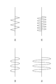
- 5 (a) to 5 (d) are diagrams for explaining a drive signal for driving the piezoelectric element.
- FIG. 6 is a diagram for explaining the arrangement of the piezoelectric elements.
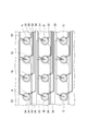
- FIG. 7 is a diagram for explaining wiring for the piezoelectric element.
- FIG. 8 is a diagram for explaining the arrangement of the piezoelectric elements in the modified example of the present embodiment.
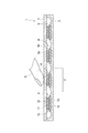
- FIG. 9 is a diagram for explaining the operation of the vibration device.
- FIG. 1 is a block diagram of a vibration device according to the present embodiment.
- FIG. 2 is a plan view of the vibration device.
- FIG. 3 is a cross-sectional view of the vibrating device.
- FIG. 4
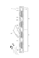
- FIG. 10 is a diagram for explaining the operation of the vibration device.
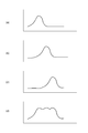
- 11 (a) to 11 (d) are diagrams for explaining the resonance frequency of the piezoelectric element.
- FIG. 12 is a diagram for explaining the position of the operating piezoelectric element in the vibration device in the modified example of the present embodiment.
- FIG. 1 is a block diagram of a vibrating device.
- FIG. 2 is a plan view of the vibration device.
- FIG. 3 is a cross-sectional view of the vibrating device.
- the vibration device 1 generates tactile feedback and sound according to the user's operation.
- the vibration device 1 is used in electronic devices such as mobile phone terminals, smartphones, personal computers, and tablet terminals.
- the vibration device 1 includes a housing 2, an operation unit 3, a plurality of vibration units 4, and a control unit 5.
- the vibration device 1 may further include a display and function as a touch panel display.
- the operation unit 3 may be a display.
- the vibration device 1 may be a tablet without a display.
- the operation unit 3 is fitted in the housing 2.
- the vibration device 1 has an accommodation space S formed by the housing 2 and the operation unit 3.
- a plurality of vibrating units 4 are accommodated in the accommodation space S.
- the vibrating device 1 has a plate shape
- the operation unit 3 also has a plate shape.
- the operation unit 3 has an operation surface 3a operated by the user.
- the operation unit 3 outputs a signal corresponding to the operation of the operation surface 3a by the user to the control unit 5.
- the operation unit 3 outputs a signal including position information on the operation surface 3a touch-operated by the user to the control unit 5.
- the "operation of the operation surface” is at least one of a case where the user operates the operation surface 3a with a part of the user's body such as a finger and a case where the user operates the operation surface 3a with an operation member such as a stylus pen. include.
- the "touch operation” includes an operation in which the user's body or operating member exerts a force on the operating surface, and an operation in which the user's body or operating member comes into contact with the operating surface and does not exert a force on the operating surface.
- the operation unit 3 includes, for example, an electrostatic touch sensor, and transmits information on a position where a part of the user's body is touching on the operation surface 3a to the control unit 5 by the above signal.
- the operation unit 3 may include a piezoelectric touch sensor instead of the electrostatic touch sensor.
- the plurality of vibrating units 4 perform tactile vibration and sounding vibration in response to a drive signal from the control unit 5.
- Tactile vibration is vibration for performing tactile feedback.
- Pronunciation vibration is vibration for producing sound.
- the plurality of vibrating portions 4 are arranged so as to overlap the operation surface 3a when viewed from a direction orthogonal to the operation surface 3a.
- the plurality of vibrating units 4 are arranged in the accommodation space S along the operation surface 3a.
- the plurality of vibrating units 4 are two-dimensionally arranged in a matrix along the operation surface 3a when viewed from a direction orthogonal to the operation surface 3a.
- the operation surface 3a has a rectangular shape, and 12 vibrating portions 4 are arranged in 3 rows and 4 columns.
- the plurality of vibrating portions 4 may be arranged on a straight line extending along the operation surface 3a, for example.
- Each vibrating unit 4 has a piezoelectric element 10 and a diaphragm 15.
- the plurality of piezoelectric elements 10 are arranged so as to overlap the operation surface 3a when viewed from a direction orthogonal to the operation surface 3a.
- the piezoelectric element 10 is provided on the diaphragm 15.
- one piezoelectric element 10 is joined to one diaphragm 15.
- the piezoelectric element 10 and the diaphragm 15 have, for example, a circular shape when viewed from a direction orthogonal to the operation surface 3a.
- the diaphragm 15 is larger than the piezoelectric element 10 in a plan view, for example. When viewed from the direction orthogonal to the operation surface 3a, the edge of the diaphragm 15 surrounds, for example, the edge of the piezoelectric element 10 joined to the diaphragm 15.
- the piezoelectric element 10 is displaced according to the drive signal from the control unit 5.
- the displacement direction of each piezoelectric element 10 by the drive signal from the control unit 5 includes a component in the direction orthogonal to the operation surface 3a. In other words, each piezoelectric element 10 is displaced in the thickness direction of the vibrating device 1.
- the piezoelectric element 10 repeats displacement according to the frequency of the drive signal.
- the diaphragm 15 vibrates by the force transmitted from the piezoelectric element 10.
- each vibration unit 4 includes one piezoelectric element 10. Therefore, in the vibration device 1, a plurality of piezoelectric elements 10 are arranged in the accommodation space S along the operation surface 3a. In other words, the plurality of piezoelectric elements 10 are arranged at different positions in the direction along the operation surface 3a. For example, the plurality of piezoelectric elements 10 are two-dimensionally arranged in a matrix along the operation surface 3a when viewed from a direction orthogonal to the operation surface 3a.
- Each piezoelectric element 10 has a resonance frequency in the audible range.
- the resonance frequency of the plurality of piezoelectric elements 10 is 20 Hz to 20,000 Hz.
- each piezoelectric element 10 is configured to have a resonance frequency of 3,000 Hz to 10,000 Hz.
- the plurality of piezoelectric elements 10 are divided into a plurality of groups having different resonance frequencies from each other, for example. That is, the plurality of piezoelectric elements 10 include at least two piezoelectric elements 10 having resonance frequencies different from each other.
- the piezoelectric element 10 has a piezoelectric element 11 and a pair of external electrodes 12 and 13.
- the piezoelectric element 11 is configured by laminating a plurality of piezoelectric layers (not shown).
- Each piezoelectric layer is made of a piezoelectric material.
- each piezoelectric layer is made of a piezoelectric ceramic material.
- Piezoelectric ceramic materials include, for example, PZT [Pb (Zr, Ti) O 3 ], PT (PbTIO 3 ), PLZT [(Pb, La) (Zr, Ti) O 3 ], or barium titanate (BaTIO 3 ). Is used.
- Each piezoelectric layer is composed of, for example, a sintered body of a ceramic green sheet containing the above-mentioned piezoelectric ceramic material.
- the plurality of piezoelectric layers are integrated to such an extent that the boundary between the piezoelectric layers cannot be recognized.
- a plurality of internal electrodes (not shown) are arranged in the piezoelectric body 11.
- Each internal electrode is made of a conductive material.
- As the conductive material for example, Ag, Pd, or Ag—Pd alloy is used.
- the diaphragm 15 is arranged between the corresponding piezoelectric element 10 and the housing 2.
- the diaphragm 15 has a pair of main surfaces 15a and 15b.
- the diaphragm 15 is joined to the corresponding piezoelectric element 10 on the main surface 15a.
- the diaphragm 15 is supported by the housing 2 on the main surface 15b. A part of the main surface 15b of the diaphragm 15 is separated from the housing 2.
- the diaphragm 15 is joined to the housing 2 at the edge of the diaphragm 15. The center of the diaphragm 15 is separated from the housing 2.
- the material of the diaphragm 15 includes, for example, at least one of brass, stainless steel, and nickel alloy.
- the control unit 5 is, for example, one or a plurality of computers composed of hardware and software such as a program.
- the control unit 5 includes, for example, a processor and a storage device as hardware.
- the processor executes an operating system, application programs, and the like.
- the storage device is composed of a ROM (Read Only Memory) and a RAM (Random Access Memory).
- the control unit 5 controls the piezoelectric element 10 of each vibrating unit 4 in response to the operation of the operation surface 3a by the user. For example, the control unit 5 controls a plurality of vibration units 4 based on the signal output from the operation unit 3. For example, the control unit 5 outputs a drive signal and controls the plurality of piezoelectric elements 10 by the drive signal.
- FIG. 4 is a diagram for explaining control of the piezoelectric element 10 by the control unit 5.
- the control unit 5 tactilely vibrates the piezoelectric element 10 corresponding to the first position ⁇ in which the operation is performed in response to the operation of the operation surface 3a by the user U.
- the control unit 5 makes the piezoelectric element 10 corresponding to the second position ⁇ sound and vibrate in response to the operation of the operation surface 3a by the user U.
- the second position ⁇ is different from the first position ⁇ in which the operation was performed.
- the first position ⁇ and the second position ⁇ are positions on the operation surface 3a, respectively.
- the first position ⁇ is a position on the operation surface 3a where the user U is touch-operated
- the second position ⁇ is a position on the operation surface 3a where the user U is not touch-operated.
- the piezoelectric element 10 corresponding to the first position ⁇ is a piezoelectric element 10 arranged at a position overlapping the first position ⁇ when viewed from a direction orthogonal to the operation surface 3a.
- the piezoelectric element 10 corresponding to the second position ⁇ is a piezoelectric element 10 arranged at a position overlapping the second position ⁇ when viewed from a direction orthogonal to the operation surface 3a.
- the piezoelectric element 10 corresponding to the first position ⁇ is one piezoelectric element 10, and the piezoelectric element 10 corresponding to the second position ⁇ is a plurality of piezoelectric elements 10.
- control unit 5 tactilely vibrates the piezoelectric element 10 located directly below the position on the operation surface 3a that the user U is touching in response to the operation of the operation surface 3a by the user U, and a plurality of piezoelectric elements. Sound and vibrate 10.
- the control unit 5 outputs a drive signal so that the plurality of piezoelectric elements 10 that vibrate soundly play a melody by changing the vibration frequency.
- the control unit 5 may output a drive signal so that the plurality of piezoelectric elements 10 that sound and vibrate generate a single sound.
- the control unit 5 outputs a drive signal to the piezoelectric element 10 corresponding to the first position ⁇ so as to vibrate at the first frequency.
- the control unit 5 outputs a drive signal to the piezoelectric element 10 corresponding to the second position ⁇ so as to vibrate at the second frequency.
- the first frequency for vibrating the piezoelectric element 10 corresponding to the first position ⁇ is lower than the resonance frequency of the piezoelectric element 10.
- the first frequency is smaller than the second frequency.
- At least the second frequency is the frequency in the audible range.
- the first frequency is, for example, 50 Hz to 200 Hz.
- the first frequency is 160 Hz.
- the second frequency is, for example, 20 Hz to 20,000 Hz.
- the second frequency is, for example, 3,000 Hz to 10,000 Hz, and varies depending on the pitch of the sound emitted by the piezoelectric element 10.
- the control unit 5 may be accommodated in the accommodation space S, or may be provided outside the accommodation space S.
- the control unit 5 may be separated from the housing 2 and the operation unit 3.
- the control unit 5 includes an acquisition unit 21, a piezoelectric element determination unit 22, a tactile signal generation unit 23, and a sound signal generation unit 24.
- the acquisition unit 21 acquires a signal corresponding to the operation of the operation surface 3a by the user U.
- the signal includes position information on the operation surface 3a touch-operated by the user U.
- the acquisition unit 21 acquires the signal output from the operation unit 3.
- the piezoelectric element determination unit 22 selects the piezoelectric element 10 to be operated according to the signal acquired by the acquisition unit 21. In other words, the piezoelectric element determination unit 22 determines the piezoelectric element 10 corresponding to the first position ⁇ and the piezoelectric element 10 corresponding to the second position ⁇ according to the signal acquired by the acquisition unit 21.
- the tactile signal generation unit 23 generates a drive signal that causes the piezoelectric element 10 to tactilely vibrate.
- the tactile signal generation unit 23 outputs the generated drive signal to the piezoelectric element 10 corresponding to the first position ⁇ determined by the piezoelectric element determination unit 22.
- the tactile signal generation unit 23 generates a drive signal that vibrates the piezoelectric element 10 at the first frequency, and outputs the drive signal to the piezoelectric element 10 corresponding to the first position ⁇ .
- the tactile signal generation unit 23 acquires the resonance frequency of the piezoelectric element 10 corresponding to the first position ⁇ .
- the tactile signal generation unit 23 determines at least one of the waveform of the drive signal that causes the piezoelectric element 10 to tactilely vibrate, the strength of the drive signal, and the frequency of the drive signal according to the acquired resonance frequency. ..
- the tactile signal generation unit 23 may read out a drive signal determined based on the resonance frequency of the piezoelectric element 10 corresponding to the first position ⁇ from the storage unit and output it.
- the drive signal may be stored in the storage unit, for example, in which at least one of the waveform, intensity, and frequency of the drive signal and the resonance frequency are associated in advance.
- the tactile signal generation unit 23 may acquire and output a drive signal determined based on the resonance frequency of the piezoelectric element 10 corresponding to the first position ⁇ from an external device of the vibration device.
- FIG. 5A to 5 (d) show an example of a drive signal that causes the piezoelectric element 10 to tactilely vibrate.
- FIG. 5A shows an example of the waveform of the reference drive signal.
- FIG. 5B shows an example of a drive signal whose waveform is changed from the reference drive signal.
- the drive signal shown in FIG. 5 (b) has a triangular wave waveform, whereas the drive signal shown in FIG. 5 (a) is the drive shown in FIG. 5 (b). It has a waveform with a shape closer to a sine wave than the signal waveform.
- FIG. 5C shows an example of a drive signal whose intensity is changed from the reference drive signal.
- the strength of the drive signal shown in FIG. 5 (c) is higher than the strength of the drive signal shown in FIG. 5 (a).
- FIG. 5D shows an example of a drive signal whose frequency is changed from the reference drive signal.
- the frequency of the drive signal shown in FIG. 5 (d) is higher than the frequency of the drive signal
- the sound signal generation unit 24 generates a drive signal that causes the piezoelectric element 10 to sound and vibrate.
- the sound signal generation unit 24 outputs the generated drive signal to the piezoelectric element 10 corresponding to the second position ⁇ determined by the piezoelectric element determination unit 22.
- the tactile signal generation unit 23 generates a drive signal that vibrates the piezoelectric element 10 at the second frequency, and outputs the drive signal to the piezoelectric element 10 corresponding to the second position ⁇ .
- FIG. 6 shows the arrangement of the piezoelectric elements 10 as viewed from the direction orthogonal to the operation surface 3a.
- FIG. 7 shows a part of the wiring for the piezoelectric element 10 in this embodiment.
- the plurality of piezoelectric elements 10 include three groups of piezoelectric elements 10.
- the piezoelectric elements 10 of these three groups have different resonance frequencies from each other.
- the plurality of piezoelectric elements 10 include at least three piezoelectric elements 10 each having a different resonance frequency.
- the plurality of piezoelectric elements 10 include a plurality of piezoelectric elements A having a first resonance frequency, a plurality of piezoelectric elements B having a second resonance frequency, and a plurality of piezoelectric elements B having a third resonance frequency. It includes a piezoelectric element C.
- a plurality of piezoelectric elements 10 are arranged in a matrix of 3 rows and 4 columns. Piezoelectric elements having the same resonance frequency when viewed from the direction orthogonal to the operation surface 3a are arranged so as to be adjacent to each other in the row direction. Piezoelectric elements having different resonance frequencies when viewed from the direction orthogonal to the operation surface 3a are arranged so as to be adjacent to each other in the row direction.
- the plurality of piezoelectric elements A are arranged in the row direction so as to be adjacent to each other without sandwiching the piezoelectric element B and the piezoelectric element C.
- the plurality of piezoelectric elements B are arranged in the row direction so as to be adjacent to each other without sandwiching the piezoelectric element A and the piezoelectric element C.
- the plurality of piezoelectric elements C are arranged in the row direction so as to be adjacent to each other without sandwiching the piezoelectric element A and the piezoelectric element B in between.
- the row in which the plurality of piezoelectric elements B are arranged is located adjacent to the row in which the plurality of piezoelectric elements A are arranged.
- the row in which the plurality of piezoelectric elements C are arranged is located adjacent to the row in which the plurality of piezoelectric elements B are arranged.
- a plurality of piezoelectric elements 10 are arranged in the order of the piezoelectric element A, the piezoelectric element B, and the piezoelectric element C in the row direction.
- FIG. 7 shows the wiring structure for the piezoelectric element 10 in the vibration device 1 shown in FIG.
- FIG. 7 shows the vibration device 1 excluding the operation unit 3.
- a pair of wirings 31 and 32 and a pair of wirings 33 and 34 are connected to each piezoelectric element 10.
- the pair of wirings 31 and 32 transmit a drive signal that causes the piezoelectric element 10 to tactilely vibrate.
- the pair of wirings 33 and 34 transmit a signal that causes the piezoelectric element 10 to sound and vibrate.
- a plurality of piezoelectric elements 10 having the same resonance frequency are connected in parallel by the same wirings 31 and 33.
- Wiring 31, 32, 33, 34 connected to a plurality of piezoelectric elements 10 having the same resonance frequency extend in the row direction between the adjacent piezoelectric elements 10.
- the wirings 32 and 34 connected to the plurality of piezoelectric elements A extend in the row direction between the group composed of the plurality of piezoelectric elements A and the group composed of the plurality of piezoelectric elements B.
- the wirings 31 and 33 connected to the plurality of piezoelectric elements B extend in the row direction between the group composed of the plurality of piezoelectric elements A and the group composed of the plurality of piezoelectric elements B.
- the wirings 32 and 34 connected to the plurality of piezoelectric elements B extend in the row direction between the group composed of the plurality of piezoelectric elements B and the group composed of the plurality of piezoelectric elements C.
- the wirings 31, 32, 33, and 34 that are different from each other are arranged so as not to overlap each other when viewed from the direction orthogonal to the operation surface 3a.
- the direction in which the wirings 31 and 32 extend from each piezoelectric element 10 is opposite to the direction in which the wirings 33 and 34 extend from each piezoelectric element 10.
- the plurality of piezoelectric elements 10 may be arranged so that the piezoelectric elements having the same resonance frequency are separated.
- FIG. 8 shows the arrangement of the piezoelectric elements 10 as viewed from the direction orthogonal to the operation surface 3a in the modified example of the present embodiment.
- the plurality of piezoelectric elements 10 have piezoelectric elements having different resonance frequencies when viewed from the direction orthogonal to the operation surface 3a, and are adjacent to each other in the row direction and the column direction. They are arranged in a matrix to fit.
- the piezoelectric element C and the piezoelectric element C are next to the row in which the piezoelectric element 10 is arranged in the row direction in the order of the piezoelectric element A, the piezoelectric element B, the piezoelectric element C, and the piezoelectric element A.
- a row in which the piezoelectric elements 10 are arranged in the row direction is located in the order of the element A, the piezoelectric element B, and the piezoelectric element C.
- the piezoelectric element 10 is arranged in the row direction in the order of the piezoelectric element C, the piezoelectric element A, the piezoelectric element B, and the piezoelectric element C, the piezoelectric element B, the piezoelectric element C, the piezoelectric element A, and the piezoelectric element B are arranged in this order.
- a row in which the piezoelectric elements 10 are arranged in the row direction is located.
- 9 and 10 are diagrams for explaining the operation of the vibrating device.
- 11 (a) to 11 (d) show the frequency characteristics of the piezoelectric element.
- FIG. 12 is a diagram for explaining the position of the operating piezoelectric element.
- the piezoelectric element located immediately below the position on the operation surface 3a operated by the user U. 10 vibrates tactilely.
- the tactile vibration of the piezoelectric element 10 is transmitted to the user U via the operation unit 3.
- the user U receives tactile feedback according to the operation of the operation unit 3.
- the piezoelectric element 10 different from the tactile vibration piezoelectric element 10 evokes and vibrates.
- a melody is emitted from the operation surface 3a by the sounding vibration of the plurality of piezoelectric elements 10.
- the plurality of piezoelectric elements 10 that sound and vibrate include piezoelectric elements A, B, and C having different resonance frequencies from each other.
- FIG. 11A shows the frequency characteristics of the piezoelectric element A.
- FIG. 11B shows the frequency characteristics of the piezoelectric element B.
- FIG. 11C shows the frequency characteristics of the piezoelectric element C.
- the frequency characteristics of the piezoelectric elements A, B, and C have peaks at frequencies different from each other. Therefore, when the frequency characteristics of the piezoelectric elements A, B, and C are combined, a waveform as shown in FIG. 11D can be obtained.
- This synthesized waveform has a larger peak width than the waveform of the frequency characteristics of the piezoelectric elements A, B, and C. Therefore, when the control unit 5 simultaneously sounds and vibrates the piezoelectric elements A, B, and C, the sound pressure level is secured in a wider frequency band than when the piezoelectric elements A, B, and C are sounded and vibrated, respectively.
- the piezoelectric element determination unit 22 of the control unit 5 is arranged at a position overlapping the first position ⁇ operated by the user U when viewed from a direction orthogonal to the operation surface 3a.
- the piezoelectric element 10 is determined as the piezoelectric element 10 corresponding to the first position ⁇ .
- the piezoelectric element determining unit 22 makes all the piezoelectric elements 10 except the piezoelectric element 10 corresponding to the first position ⁇ the piezoelectric element 10 corresponding to the second position ⁇ . To determine as. That is, the second position ⁇ is the entire region on the operation surface 3a except the first position ⁇ .
- the control unit 5 does not have to vibrate a part of the plurality of piezoelectric elements 10 included in the vibration device 1.
- the control unit 5 makes the piezoelectric element 10 corresponding to the first position ⁇ tactilely vibrate, causes the piezoelectric element 10 corresponding to the second position ⁇ to sound and vibrate, and causes the operation surface 3a.
- the piezoelectric element 10 corresponding to the third position ⁇ which is different from the first position ⁇ and the second position ⁇ , is not vibrated.
- the control unit 5 does not vibrate the piezoelectric element 10 corresponding to the third position ⁇ while vibrating the piezoelectric element 10 corresponding to the first position ⁇ and the piezoelectric element 10 corresponding to the second position ⁇ . For example, the control unit 5 prohibits the vibration of the piezoelectric element 10 corresponding to the third position ⁇ until the position operated by the user U is changed.
- the second position ⁇ is a position previously associated with the first position ⁇ .
- the vibration device 1 stores the relative position information of the second position ⁇ with respect to the first position ⁇ in advance in a memory (not shown).
- the piezoelectric element determination unit 22 of the control unit 5 acquires the relative position information and determines the relative position information as the first position ⁇ or the first position ⁇ .
- the piezoelectric element 10 corresponding to the second position ⁇ is determined based on the piezoelectric element 10 corresponding to the position ⁇ .
- the piezoelectric element determination unit 22 of the control unit 5 positions the piezoelectric element 10 arranged at a position overlapping the first position ⁇ operated by the user U when viewed from a direction orthogonal to the operation surface 3a. It is determined as the piezoelectric element 10 corresponding to ⁇ .
- the piezoelectric element determining unit 22 is adjacent to the piezoelectric element 10 corresponding to the first position ⁇ when viewed from the direction orthogonal to the operation surface 3a in all directions or in eight directions.
- the piezoelectric element 10 is determined as the piezoelectric element 10 corresponding to the second position ⁇ . “Four sides” means the vertical and horizontal directions on the operation surface 3a.
- “Happo” means the vertical, horizontal, and diagonal directions on the operation surface 3a.
- the piezoelectric element determining unit 22 uses all the piezoelectric elements 10 except the piezoelectric element 10 corresponding to the first position ⁇ and the piezoelectric element 10 corresponding to the second position ⁇ . , The piezoelectric element 10 corresponding to the third position ⁇ is determined.
- the vibration device 1 includes a plurality of piezoelectric elements 10.
- the plurality of piezoelectric elements 10 are arranged at different positions in the direction along the operation surface 3a.
- the control unit 5 vibrates the piezoelectric element 10 corresponding to the first position ⁇ operated by the user U on the operation surface 3a among the plurality of piezoelectric elements 10. Further, the control unit 5 vibrates the piezoelectric element 10 corresponding to the second position ⁇ different from the first position ⁇ on the operation surface 3a among the plurality of piezoelectric elements 10 according to the frequency in the audible range.
- the vibration device 1 can generate tactile feedback to the user U by the vibration of the piezoelectric element 10 corresponding to the first position ⁇ , and also generates sound by the piezoelectric element 10 corresponding to the second position ⁇ . Can be done.
- the piezoelectric element 10 that generates tactile feedback and the piezoelectric element 10 that generates sound are arranged at different positions in the direction along the operation surface 3a. Therefore, the size is reduced in the direction orthogonal to the operation surface 3a.
- the plurality of piezoelectric elements 10 are arranged so as to overlap the operation surface 3a when viewed from a direction orthogonal to the operation surface 3a. Therefore, the user U can feel that the sound is being emitted from the operation surface 3a. That is, in a compact configuration, the vibration device 1 can give tactile feedback to the user U and also give a sense of presence by sound.
- Each piezoelectric element 10 has a resonance frequency in the audible range. According to this configuration, the sound pressure level of the sound emitted from the piezoelectric element 10 corresponding to the second position ⁇ is further improved.
- the first frequency for vibrating the piezoelectric element 10 corresponding to the first position ⁇ is lower than the resonance frequency of the piezoelectric element 10. According to this configuration, the sensitivity of the tactile feedback by the user U is improved, and the sound pressure level of the sound emitted from the piezoelectric element 10 corresponding to the second position ⁇ is further improved.
- the plurality of piezoelectric elements 10 include at least two piezoelectric elements 10 having resonance frequencies different from each other.
- the control unit 5 determines the waveform of the drive signal that vibrates the piezoelectric element 10 corresponding to the first position ⁇ , the strength of the drive signal, and the drive signal based on the resonance frequency of the piezoelectric element 10 corresponding to the first position ⁇ . Outputs a signal in which at least one of the frequencies has been determined. According to this configuration, the user U can improve the sensitivity of the tactile feedback while ensuring the sound pressure level of the sound emitted from the piezoelectric element 10 corresponding to the second position ⁇ .
- the plurality of piezoelectric elements 10 include a plurality of piezoelectric elements 10 having a first resonance frequency and a plurality of piezoelectric elements 10 having a second resonance frequency different from the first resonance frequency. According to this configuration, even if any one of the plurality of piezoelectric elements 10 is tactilely vibrated, the remaining piezoelectric elements 10 include a plurality of piezoelectric elements 10 having different resonance frequencies from each other. Therefore, the sound pressure level is ensured in a wider frequency band. Therefore, the vibration device 1 can secure the sound pressure level of each pitch and emit a melody from the piezoelectric element 10 corresponding to the second position ⁇ .
- the plurality of piezoelectric elements 10 include at least three piezoelectric elements 10 having different resonance frequencies. According to this configuration, even if any one of the plurality of piezoelectric elements 10 vibrates tactilely, the remaining piezoelectric elements 10 include a plurality of piezoelectric elements 10 having different resonance frequencies from each other. Therefore, the sound pressure level is ensured in a wider frequency band. Therefore, the vibration device 1 can secure the sound pressure level of each pitch and emit a melody from the piezoelectric element 10 corresponding to the second position ⁇ .
- the control unit 5 includes the piezoelectric element 10 corresponding to the first position ⁇ , the piezoelectric element 10 corresponding to the second position ⁇ , and the first position ⁇ and the second position on the operation surface 3a.
- the piezoelectric element 10 corresponding to the third position ⁇ different from ⁇ is determined.
- the control unit 5 does not vibrate the piezoelectric element 10 corresponding to the third position ⁇ while vibrating the piezoelectric element 10 corresponding to the first position ⁇ and the piezoelectric element 10 corresponding to the second position ⁇ . According to this configuration, sound is emitted from an appropriate position depending on the situation.
- the plurality of piezoelectric elements 10 are arranged in a matrix. Piezoelectric elements 10 having the same resonance frequency when viewed from a direction orthogonal to the operation surface 3a are adjacent to each other in the row direction. Piezoelectric elements 10 having different resonance frequencies are adjacent to each other in the column direction. According to this configuration, the arrangement of the wirings 31, 32, 33, 34 with respect to the piezoelectric element 10 can be simplified. Therefore, the size of the vibration device 1 can be further reduced.
- the plurality of piezoelectric elements 10 are arranged in a matrix so that the piezoelectric elements 10 having different resonance frequencies in the row direction and the column direction are adjacent to each other when viewed from the direction orthogonal to the operation surface 3a. In this configuration, since the piezoelectric elements 10 having different resonance frequencies are located separately, the vibrating device 1 emits a sound having a uniform sound pressure level in each direction.
- the piezoelectric element 10 may be displaced by a force transmitted through the operation unit 3 pressed by the user U, and an electric signal generated by this displacement may be output to the control unit 5.
- the control unit 5 may control a plurality of vibration units 4 based on the signal output from the piezoelectric element 10.
- the control unit 5 detects which piezoelectric element 10 is the signal output from the signal output from the piezoelectric element 10, and acquires the position information on the operation surface 3a touch-operated by the user U.
- the acquisition unit 21 of the control unit 5 acquires the signal output from the piezoelectric element 10 or the position information of the piezoelectric element 10.
- the piezoelectric element determination unit 22 of the control unit 5 determines the piezoelectric element 10 corresponding to the first position ⁇ and the piezoelectric element 10 corresponding to the second position ⁇ based on the position information.
- the plurality of piezoelectric elements 10 are composed of three groups of piezoelectric elements 10 having different resonance frequencies from each other.
- the plurality of piezoelectric elements 10 may consist of two groups of piezoelectric elements 10 having resonance frequencies different from each other.
- the plurality of piezoelectric elements 10 may consist of four or more groups of piezoelectric elements 10 having different resonance frequencies from each other.
- piezoelectric elements 10 having different resonance frequencies are arranged for each row.
- the piezoelectric elements 10 having different resonance frequencies may be arranged for each of a plurality of rows.
- a plurality of piezoelectric elements 10 may be arranged in the order of the piezoelectric element A, the piezoelectric element A, the piezoelectric element B, the piezoelectric element B, the piezoelectric element C, and the piezoelectric element C.
- the long side direction of the operation surface 3a is the row direction
- the short side direction is the column direction
- the long side direction of the operation surface 3a may be the column direction
- the short side direction may be the row direction
- the piezoelectric elements 10 having the same resonance frequency are regularly arranged so as to be separated.
- the piezoelectric elements 10 having the same resonance frequency may be arranged irregularly.
- the arrangement of the plurality of piezoelectric elements 10 may be randomly determined by software or the like.
- the control unit 5 may cause the piezoelectric element 10 corresponding to the first position ⁇ to perform sound vibration as well as tactile vibration.
- the control unit 5 causes the piezoelectric element 10 located immediately below the position operated by the user U to vibrate to generate a sound together with the other piezoelectric elements 10, and this vibration causes the user U to vibrate via the operation surface 3a. It may be transmitted.
- the control unit 5 may cause the piezoelectric element 10 located immediately below the position operated by the user U to perform sound vibration immediately after the tactile vibration is performed.
- Vibration device 3 ... Operation unit, 3a ... Operation surface, 5 ... Control unit, 10, A, B, C ... Piezoelectric element, U ... User, ⁇ ... First position, ⁇ ... Second position, ⁇ ... First Three positions.
Landscapes
- Engineering & Computer Science (AREA)
- General Engineering & Computer Science (AREA)
- Theoretical Computer Science (AREA)
- Physics & Mathematics (AREA)
- Human Computer Interaction (AREA)
- General Physics & Mathematics (AREA)
- Acoustics & Sound (AREA)
- Signal Processing (AREA)
- Multimedia (AREA)
- User Interface Of Digital Computer (AREA)
- Piezo-Electric Transducers For Audible Bands (AREA)
- Diaphragms For Electromechanical Transducers (AREA)
- Details Of Audible-Bandwidth Transducers (AREA)
Abstract
振動デバイス1において、操作部3は、ユーザによって操作される操作面を有している。複数の圧電素子10は、操作面に直交する方向から見て操作面と重なるように配置されている。複数の圧電素子10は、操作面に沿った方向において互いに異なる位置に配置されている。制御部5は、複数の圧電素子10を制御する。制御部5は、ユーザによる操作面の操作に応じて、複数の圧電素子10のうち、操作面上における当該操作がなされた第一位置に対応する圧電素子10を第一周波数によって振動させ、かつ、複数の圧電素子10のうち、操作面上における第一位置と異なる第二位置に対応する圧電素子10を第一周波数と異なる第二周波数によって振動させる。第二周波数は、可聴域の周波数である。
Description
本発明は、振動デバイスに関する。
ユーザによって操作される操作部と、ユーザによる操作部の操作に応じて振動する圧電素子とを備えた振動デバイスが知られている。たとえば、特許文献1は、ディスプレイと圧電素子とを備えた電子機器を記載している。この圧電素子は、ユーザによるディスプレイの操作に応じて振動する。
特許文献1は、上記圧電素子に加えてスピーカを含む複合素子を電子機器に設けることを記載している。この電子機器は、ユーザがディスプレイなどの操作部の操作面を操作した場合に、複合素子の圧電素子において触覚フィードバックを行い、複合素子のスピーカにおいて音を発生させる発音振動を行う。上記複合素子において、ディスプレイの厚さ方向に、圧電素子とスピーカとが配列されている。このような構成において、ディスプレイなどの操作面の厚さ方向における電子機器のサイズが削減され難い。
本発明の一つの態様は、コンパクトな構成において、ユーザの操作に応じて触覚フィードバックと音とを発生させることができる振動デバイスを提供することを目的とする。
本発明の一つの態様における振動デバイスは、操作部と、複数の圧電素子と、制御部とを備えている。操作部は、ユーザによって操作される操作面を有している。複数の圧電素子は、操作面に直交する方向から見て操作面と重なるように配置されている。複数の圧電素子は、操作面に沿った方向において互いに異なる位置に配置されている。制御部は、複数の圧電素子を制御する。制御部は、ユーザによる操作面の操作に応じて、複数の圧電素子のうち、操作面上における当該操作がなされた第一位置に対応する圧電素子を第一周波数によって振動させ、かつ、複数の圧電素子のうち、操作面上における第一位置と異なる第二位置に対応する圧電素子を第一周波数と異なる第二周波数によって振動させる。第二周波数は、可聴域の周波数である。
この振動デバイスは、複数の圧電素子を備えている。複数の圧電素子は、操作面に沿った方向において互いに異なる位置に配置されている。制御部は、上記複数の圧電素子のうち、操作面上におけるユーザの操作がなされた第一位置に対応する圧電素子を振動させる。さらに、制御部は、上記複数の圧電素子のうち、操作面上における第一位置と異なる第二位置に対応する圧電素子を可聴域の周波数によって振動させる。この振動デバイスは、第一位置に対応する圧電素子の振動によってユーザに対して触覚フィードバックを発生させることができると共に、第二位置に対応する圧電素子によって音を発生させることができる。触覚フィードバックを発生させる圧電素子と音を発生させる圧電素子とが、操作面に沿った方向において異なる位置に配置されている。このため、操作面に直交する方向においてサイズが削減される。
上記一つの態様において、各圧電素子は、可聴域の共振周波数を有していてもよい。この構成によれば、第二位置に対応する圧電素子から発せられる音の音圧レベルがより向上する。
上記一つの態様において、第一位置に対応する圧電素子を振動させる第一周波数は、当該圧電素子の共振周波数よりも低くてもよい。この構成によれば、ユーザによる触覚フィードバックの感度が向上すると共に、第二位置に対応する圧電素子から発する音の音圧レベルがより向上する。
上記一つの態様において、複数の圧電素子は、互いに異なる共振周波数を有している少なくとも2つの圧電素子を含んでもよい。制御部は、第一位置に対応する圧電素子の共振周波数に基づいて、第一位置に対応する圧電素子を振動させる駆動信号の波形と、駆動信号の強度と、駆動信号の周波数と、の少なくとも1つが決定された信号を出力してもよい。この構成によれば、第二位置に対応する圧電素子から発する音の音圧レベルが確保されながら、ユーザが触覚フィードバックの感度が向上し得る。
上記一つの態様において、複数の圧電素子は、第一共振周波数を有している複数の圧電素子と、第一共振周波数と異なる第二共振周波数を有している複数の圧電素子とを含んでもよい。この構成によれば、複数の圧電素子のうちいずれか1つが触覚振動していても、残りの圧電素子に、互いに共振周波数の異なる複数の圧電素子が含まれている。このため、より広い周波数帯域において、音圧レベルが確保される。
上記一つの態様において、複数の圧電素子は、それぞれ異なる共振周波数を有している少なくとも3つの圧電素子を含んでいてもよい。この構成によれば、複数の圧電素子のうちいずれか1つが触覚振動しても、残りの圧電素子に、互いに共振周波数の異なる複数の圧電素子が含まれている。このため、より広い周波数帯域において、音圧レベルが確保される。
上記一つの態様において、制御部は、複数の圧電素子のうち、第一位置に対応する圧電素子と、第二位置に対応する圧電素子と、操作面上における第一位置及び第二位置と異なる第三位置に対応する圧電素子と、を決定してもよい。制御部は、第一位置に対応する圧電素子及び第二位置に対応する圧電素子を振動させている間、第三位置に対応する圧電素子を振動させなくてもよい。この構成によれば、状況に応じて適切な位置から音が発せられる。
上記一つの態様において、複数の圧電素子は、行列状に配列されていてもよい。同一の共振周波数を有している圧電素子は、操作面に直交する方向から見て、行方向において互いに隣り合っていてもよい。互いに異なる共振周波数を有している圧電素子は、操作面に直交する方向から見て、列方向において隣り合っていてもよい。この構成によれば、圧電素子に対する配線の配置が簡素化され得る。このため、振動デバイスのサイズがさらに削減され得る。
上記一つの態様において、複数の圧電素子は、操作面に直交する方向から見て、行方向及び列方向において互いに異なる共振周波数を有している圧電素子が隣り合うように行列状に配列されていてもよい。この構成において、異なる共振周波数を有している圧電素子がばらけて位置しているため、振動デバイスから各方向に均等な音圧レベルの音が発せられる。
本発明の一つの態様は、コンパクトな構成において、ユーザの操作に応じて触覚フィードバックと音とを発生させることができる振動デバイスを提供する。
以下、添付図面を参照しながら本発明の実施形態が詳細に説明される。図面の説明において、同一又は同等の要素には同一符号が用いられ、重複する説明は省略される。
まず、図1から図4を参照して、本実施形態における振動デバイスの構成を説明する。図1は、振動デバイスのブロック図である。図2は、振動デバイスの平面図である。図3は、振動デバイスの断面図である。
振動デバイス1は、ユーザの操作に応じて、触覚フィードバックと音とを発生させる。振動デバイス1は、たとえば、携帯電話端末、スマートフォン、パーソナルコンピュータ、タブレット端末などの電子機器に用いられる。振動デバイス1は、筐体2と、操作部3と、複数の振動部4と、制御部5とを備えている。振動デバイス1は、さらにディスプレイを備えて、タッチパネルディスプレイとして機能してもよい。この場合、操作部3が、ディスプレイであってもよい。振動デバイス1は、ディスプレイを備えていないタブレットであってもよい。
図2に示されているように、操作部3は、筐体2にはめ込まれている。振動デバイス1は、筐体2と操作部3とによって形成されている収容空間Sを有している。収容空間Sには、複数の振動部4が収容されている。たとえば、振動デバイス1は板形状を呈しており、操作部3も板形状を呈している。
操作部3は、ユーザによって操作される操作面3aを有している。操作部3は、ユーザによる操作面3aの操作に応じた信号を制御部5に出力する。操作部3は、ユーザがタッチ操作した操作面3a上の位置情報を含む信号を制御部5に出力する。「操作面の操作」は、ユーザが指などユーザの体の一部によって操作面3aを操作する場合と、ユーザがスタイラスペンなどの操作部材によって操作面3aを操作する場合との少なくとも1つを含む。「タッチ操作」は、ユーザの体又は操作部材が操作面に対して力を与える操作と、ユーザの体又は操作部材が操作面に接触して当該操作面に力を与えない操作とを含む。操作部3は、たとえば、静電式タッチセンサを含み、操作面3aにおいてユーザの体の一部が触れている位置の情報を上記信号によって制御部5に伝達する。操作部3は、静電式タッチセンサの代わりに、圧電式タッチセンサを含んでいてもよい。
複数の振動部4は、制御部5から駆動信号に応じて、触覚振動と発音振動とを行う。触覚振動は、触覚フィードバックを行うための振動である。発音振動は、音を発するための振動である。複数の振動部4は、操作面3aに直交する方向から見て操作面3aと重なるように配置されている。複数の振動部4は、収容空間Sに操作面3aに沿って配列されている。たとえば、複数の振動部4は、操作面3aに直交する方向から見て、操作面3aに沿って行列状に2次元配列されている。たとえば、操作面3aは矩形状であり、12個の振動部4が3行4列で配列されている。複数の振動部4は、たとえば、操作面3aに沿って延在する直線上に配列されていてもよい。
各振動部4は、圧電素子10と、振動板15とを有している。複数の圧電素子10は、操作面3aに直交する方向から見て操作面3aと重なるように配置されている。圧電素子10は、振動板15に設けられている。たとえば、1つの圧電素子10が1つの振動板15に接合されている。圧電素子10及び振動板15は、操作面3aに直交する方向から見て、たとえば円形形状を呈している。振動板15は、たとえば、平面視で圧電素子10よりも大きい。操作面3aに直交する方向から見て、振動板15の縁は、たとえば、当該振動板15に接合されている圧電素子10の縁を囲っている。
圧電素子10は、制御部5からの駆動信号に応じて変位する。制御部5からの駆動信号による各圧電素子10の変位方向は、操作面3aに直交する方向の成分を含んでいる。換言すれば、各圧電素子10は、振動デバイス1の厚み方向に変位する。圧電素子10は、駆動信号の周波数に応じて変位を繰り返す。振動板15は、圧電素子10から伝達された力によって振動する。
振動デバイス1において、各振動部4は1つの圧電素子10を含んでいる。このため、振動デバイス1において、複数の圧電素子10が、収容空間Sに操作面3aに沿って配列されている。換言すれば、複数の圧電素子10は、操作面3aに沿った方向において互いに異なる位置に配置されている。たとえば、複数の圧電素子10は、操作面3aに直交する方向から見て、操作面3aに沿って行列状に2次元配列されている。
各圧電素子10は、可聴域の共振周波数を有している。複数の圧電素子10の共振周波数は、20Hz~20,000Hzである。たとえば、各圧電素子10は、共振周波数が3,000Hz~10,000Hzとなるように構成されている。複数の圧電素子10は、たとえば、互いに異なる共振周波数を有している複数のグループに分かれている。すなわち、複数の圧電素子10は、互いに異なる共振周波数を有している少なくとも2つの圧電素子10を含んでいる。
圧電素子10は、圧電素体11と、一対の外部電極12,13と、を有している。圧電素体11は、複数の圧電体層(不図示)が積層されて構成されている。各圧電体層は、圧電材料からなる。たとえば、各圧電体層は、圧電セラミック材料からなる。圧電セラミック材料には、例えば、PZT[Pb(Zr、Ti)O3]、PT(PbTiO3)、PLZT[(Pb,La)(Zr、Ti)O3]、又はチタン酸バリウム(BaTiO3)が用いられている。各圧電体層は、たとえば、上述した圧電セラミック材料を含むセラミックグリーンシートの焼結体から構成される。実際の圧電素体11において、複数の圧電体層は、各圧電体層の間の境界が認識できない程度に一体化されている。圧電素体11内には、複数の内部電極(不図示)が配置されている。各内部電極は、導電性材料からなる。導電性材料には、たとえば、Ag、Pd、又はAg-Pd合金が用いられている。
振動板15は、対応する圧電素子10と筐体2との間に配置されている。振動板15は、一対の主面15a,15bを有している。振動板15は、主面15aにおいて、対応する圧電素子10に接合されている。振動板15は、主面15bにおいて筐体2に支持されている。振動板15の主面15bの一部は、筐体2と離間している。振動板15は、当該振動板15の縁部において筐体2と接合されている。振動板15の中央は、筐体2と離間している。振動板15の材料には、たとえば、黄銅、ステンレス鋼、及びニッケル合金の少なくとも1つが含まれている。
制御部5は、例えば、ハードウェアと、プログラム等のソフトウェアとにより構成された1又は複数のコンピュータである。制御部5は、ハードウェアとして、例えば、プロセッサと、記憶装置とを備えている。プロセッサは、オペレーティングシステム及びアプリケーション・プログラムなどを実行する。記憶装置は、ROM(Read Only Memory)及びRAM(Random Access Memory)により構成される。
制御部5は、ユーザによる操作面3aの操作に応じて、各振動部4の圧電素子10を制御する。たとえば、制御部5は、操作部3から出力された信号に基づいて、複数の振動部4を制御する。たとえば、制御部5は、駆動信号を出力し、当該駆動信号によって複数の圧電素子10を制御する。図4は、制御部5による圧電素子10の制御を説明するための図である。
図4に示されているように、制御部5は、ユーザUによる操作面3aの操作に応じて、当該操作がなされた第一位置αに対応する圧電素子10を触覚振動させる。制御部5は、ユーザUによる操作面3aの操作に応じて、第二位置βに対応する圧電素子10を発音振動させる。第二位置βは、当該操作がなされた第一位置αと異なる。第一位置α及び第二位置βは、それぞれ操作面3a上の位置である。第一位置αは操作面3aのうちユーザUがタッチ操作している位置であり、第二位置βは操作面3aのうちユーザUがタッチ操作していない位置である。
たとえば、第一位置αに対応する圧電素子10は、操作面3aに直交する方向から見て、第一位置αと重なる位置に配置されている圧電素子10である。第二位置βに対応する圧電素子10は、操作面3aに直交する方向から見て、第二位置βと重なる位置に配置されている圧電素子10である。第一位置αに対応する圧電素子10は1つの圧電素子10であり、第二位置βに対応する圧電素子10は複数の圧電素子10である。たとえば、制御部5は、ユーザUによる操作面3aの操作に応じて、ユーザUがタッチ操作している操作面3a上の位置の直下に位置する圧電素子10を触覚振動させ、複数の圧電素子10を発音振動させる。たとえば、制御部5は、発音振動する複数の圧電素子10が振動周波数の変化によってメロディを奏でるように駆動信号を出力する。制御部5は、発音振動する複数の圧電素子10が単一の音を発生させるように駆動信号を出力してもよい。
制御部5は、第一位置αに対応する圧電素子10に対して、第一周波数で振動するように駆動信号を出力する。制御部5は、第二位置βに対応する圧電素子10に対して、第二周波数で振動するように駆動信号を出力する。第一位置αに対応する圧電素子10を振動させる第一周波数は、当該圧電素子10の共振周波数よりも低い。第一周波数は、第二周波数よりも小さい。少なくとも第二周波数は、可聴域の周波数である。第一周波数は、たとえば、50Hz~200Hzである。たとえば、第一周波数は、160Hzである。第二周波数は、たとえば、20Hz~20,000Hzである。第二周波数は、たとえば、3,000Hz~10,000Hzであり、圧電素子10が発する音の音程によって異なる。
制御部5は、収容空間Sに収容されていてもよいし、収容空間Sの外部に設けられていてもよい。制御部5は、筐体2及び操作部3から離間していてもよい。制御部5は、取得部21と、圧電素子決定部22と、触覚信号生成部23と、音信号生成部24とを有している。
取得部21は、ユーザUによる操作面3aの操作に応じた信号を取得する。当該信号は、ユーザUがタッチ操作した操作面3a上の位置情報を含んでいる。たとえば、取得部21は、操作部3から出力された信号を取得する。
圧電素子決定部22は、取得部21によって取得された信号に応じて、動作させる圧電素子10を選択する。換言すれば、圧電素子決定部22は、取得部21によって取得された信号に応じて、第一位置αに対応する圧電素子10と第二位置βに対応する圧電素子10とを決定する。
触覚信号生成部23は、圧電素子10を触覚振動させる駆動信号を生成する。触覚信号生成部23は、圧電素子決定部22によって決定された第一位置αに対応する圧電素子10に、生成した駆動信号を出力する。換言すれば、触覚信号生成部23は、圧電素子10を第一周波数で振動させる駆動信号を生成し、第一位置αに対応する圧電素子10に当該駆動信号を出力する。たとえば、触覚信号生成部23は、第一位置αに対応する圧電素子10の共振周波数を取得する。触覚信号生成部23は、取得された共振周波数に応じて、当該圧電素子10を触覚振動させる駆動信号の波形と、当該駆動信号の強度と、当該駆動信号の周波数との少なくとも1つを決定する。
本実施形態の変形例として、触覚信号生成部23は、第一位置αに対応する圧電素子10の共振周波数に基づいて決定された駆動信号を、記憶部から読み出して出力してもよい。この場合、駆動信号は、たとえば、駆動信号の波形、強度、及び周波数の少なくとも1つと共振周波数とが予め対応付けられて記憶部に格納されていてもよい。触覚信号生成部23は、第一位置αに対応する圧電素子10の共振周波数に基づいて決定された駆動信号を振動デバイスの外部の装置から取得して出力してもよい。
図5(a)から図5(d)は、圧電素子10を触覚振動させる駆動信号の一例を示している。図5(a)は、基準の駆動信号の波形の一例を示している。図5(b)は、基準の駆動信号から波形を変化させた駆動信号の一例を示している。図5(b)に示されている駆動信号は三角波の波形を有しているのに対して、図5(a)に示されている駆動信号は図5(b)に示されている駆動信号の波形よりも正弦波に近い形状の波形を有している。図5(c)は、基準の駆動信号から強度を変化させた駆動信号の一例を示している。図5(c)に示されている駆動信号の強度は、図5(a)に示されている駆動信号の強度よりも大きい。図5(d)は、基準の駆動信号から周波数を変化させた駆動信号の一例を示している。図5(d)に示されている駆動信号の周波数は、図5(a)に示されている駆動信号の周波数よりも大きい。
音信号生成部24は、圧電素子10を発音振動させる駆動信号を生成する。音信号生成部24は、圧電素子決定部22によって決定された第二位置βに対応する圧電素子10に、生成した駆動信号を出力する。換言すれば、触覚信号生成部23は、圧電素子10を第二周波数で振動させる駆動信号を生成し、第二位置βに対応する圧電素子10に当該駆動信号を出力する。
次に、図6及び図7を参照して、振動デバイス1における圧電素子10の構成の一例について詳細に説明する。図6は、操作面3aに直交する方向から見た圧電素子10の配置を示している。図7は、本実施形態における圧電素子10に対する配線の一部を示している。
図6に示されている振動デバイス1において、複数の圧電素子10は、3つのグループの圧電素子10を含んでいる。この3つのグループの圧電素子10は、互いに異なる共振周波数を有している。換言すれば、複数の圧電素子10は、それぞれ異なる共振周波数を有している少なくとも3つの圧電素子10を含んでいる。複数の圧電素子10は、第一共振周波数を有している複数の圧電素子Aと、第二共振周波数を有している複数の圧電素子Bと、第三共振周波数を有している複数の圧電素子Cとを含んでいる。
図6に示されている振動デバイス1において、複数の圧電素子10は、3行4列の行列状に配列されている。操作面3aに直交する方向から見て、同一の共振周波数を有している圧電素子が行方向において互いに隣り合うように配列されている。操作面3aに直交する方向から見て、互いに異なる共振周波数を有している圧電素子が列方向において互いに隣り合うように配列されている。
たとえば、複数の圧電素子Aは、圧電素子B及び圧電素子Cを間に挟まず、互いに隣り合うように行方向に配列されている。複数の圧電素子Bは、圧電素子A及び圧電素子Cを間に挟まず、互いに隣り合うように行方向に配列されている。複数の圧電素子Cは、圧電素子A及び圧電素子Bを間に挟まず、互いに隣り合うように行方向に配列されている。複数の圧電素子Aが配列されている行と隣り合うように、複数の圧電素子Bが配列されている行が位置している。複数の圧電素子Bが配列されている行と隣り合うように、複数の圧電素子Cが配列されている行が位置している。列方向において圧電素子A、圧電素子B、圧電素子Cの順で、複数の圧電素子10が配列されている。
図7は、図6に示されている振動デバイス1における圧電素子10に対する配線構造を示している。図7は、振動デバイス1から操作部3を除外して示している。各圧電素子10には、一対の配線31,32と、一対の配線33,34とが接続されている。一対の配線31、32は、当該圧電素子10を触覚振動させる駆動信号を伝達する。一対の配線33、34は、当該圧電素子10を発音振動させる信号を伝達する。同一の共振周波数を有している複数の圧電素子10は、同一の配線31,33によって並列に接続されている。同一の共振周波数を有している複数の圧電素子10に接続された配線31,32,33,34は、隣り合う圧電素子10との間において行方向に延在している。
複数の圧電素子Aに接続された配線32,34は、複数の圧電素子Aからなるグループと複数の圧電素子Bからなるグループとの間において行方向に延在している。複数の圧電素子Bに接続された配線31,33は、複数の圧電素子Aからなるグループと複数の圧電素子Bからなるグループとの間において行方向に延在している。複数の圧電素子Bに接続された配線32,34は、複数の圧電素子Bからなるグループと複数の圧電素子Cからなるグループとの間において行方向に延在している。互い異なる配線31,32,33,34は、操作面3aに直交する方向から見て、互いに重ならないように配置されている。配線31,32が各圧電素子10から延在する方向は、配線33,34が各圧電素子10から延在する方向と反対である。
本実施形態の変形例として、複数の圧電素子10は、共振周波数の同一の圧電素子がばらけるように配列されてもよい。図8は、本実施形態の変形例において、操作面3aに直交する方向から見た圧電素子10の配置を示している。図8に示されている振動デバイス1において、複数の圧電素子10は、操作面3aに直交する方向から見て、互いに異なる共振周波数を有している圧電素子が行方向及び列方向において互いに隣り合うように行列状に配列されている。図8に示されている振動デバイス1において、圧電素子A、圧電素子B、圧電素子C、圧電素子Aの順で圧電素子10が行方向に配列された行の隣に、圧電素子C、圧電素子A、圧電素子B、圧電素子Cの順で圧電素子10が行方向に配列された行が位置している。圧電素子C、圧電素子A、圧電素子B、圧電素子Cの順で圧電素子10が行方向に配列された行の隣に、圧電素子B、圧電素子C、圧電素子A、圧電素子Bの順で圧電素子10が行方向に配列された行が位置している。
次に、図4、及び、図9から図12を参照して、振動デバイス1の動作について説明する。図9及び図10は、振動デバイスの動作を説明するための図である。図11(a)から図11(d)は、圧電素子の周波数特性を示している。図12は、動作する圧電素子の位置を説明するための図である。
図9に示されているように、振動デバイス1において、ユーザUによって操作部3の操作面3aが操作されると、ユーザUによって操作された操作面3a上の位置の直下に位置する圧電素子10が触覚振動する。圧電素子10の触覚振動は、操作部3を介して、ユーザUに伝達される。この結果、ユーザUは、操作部3の操作に応じた触覚フィードバックを受ける。
図10に示されているように、振動デバイス1において、ユーザUによって操作部3の操作面3aが操作されると、触覚振動した圧電素子10とは異なる圧電素子10が発音振動する。たとえば、複数の圧電素子10が発音振動することによって、操作面3aからメロディが発せされる。発音振動する複数の圧電素子10は、互いに異なる共振周波数を有している圧電素子A,B,Cを含んでいる。
図11(a)は、圧電素子Aの周波数特性を示している。図11(b)は、圧電素子Bの周波数特性を示している。図11(c)は、圧電素子Cの周波数特性を示している。図11(a)から図11(c)に示されているように、圧電素子A,B,Cの周波数特性は、互いに異なる周波数にピークを有している。このため、圧電素子A,B,Cの周波数特性が合成されると、図11(d)に示されているような波形が得られる。この合成された波形は、各圧電素子A,B,Cの周波数特性の波形よりもピーク幅が大きい。したがって、制御部5が圧電素子A,B,Cを同時に発音振動させることで、圧電素子A,B,Cをそれぞれ発音振動させるよりも広い周波数帯域において音圧レベルが確保される。
たとえば、図4に示されているように、制御部5の圧電素子決定部22は、操作面3aに直交する方向から見て、ユーザUによる操作がなされた第一位置αと重なる位置に配置された圧電素子10を、第一位置αに対応する圧電素子10として決定する。圧電素子決定部22は、振動デバイス1に含まれる複数の圧電素子10のうち、第一位置αに対応する圧電素子10を除く全ての圧電素子10を、第二位置βに対応する圧電素子10として決定する。すなわち、第二位置βは、操作面3a上において第一位置αを除く全ての領域である。
本実施形態の変形例として、制御部5は、振動デバイス1に含まれる複数の圧電素子10のうち、一部を振動させなくてもよい。たとえば、制御部5は、図12に示されているように、第一位置αに対応する圧電素子10を触覚振動させ、第二位置βに対応する圧電素子10を発音振動させ、操作面3a上において第一位置α及び第二位置βと異なる第三位置γに対応する圧電素子10を振動させない。制御部5は、第一位置αに対応する圧電素子10及び第二位置βに対応する圧電素子10を振動させている間、第三位置γに対応する圧電素子10を振動させない。たとえば、制御部5は、ユーザUによって操作される位置が変更されるまで、第三位置γに対応する圧電素子10の振動を禁止する。
本変形例において、第二位置βは、予め第一位置αと関連付けられた位置である。たとえば、振動デバイス1は、第一位置αに対する第二位置βの相対位置情報を不図示のメモリに予め格納している。制御部5の圧電素子決定部22は、第一位置αに対応する圧電素子10が決定されると、上記相対位置情報を取得し、当該相対位置情報と決定された第一位置α又は第一位置αに対応する圧電素子10とに基づいて、第二位置βに対応する圧電素子10を決定する。
たとえば、制御部5の圧電素子決定部22は、操作面3aに直交する方向から見て、ユーザUによる操作がなされた第一位置αと重なる位置に配置された圧電素子10を、第一位置αに対応する圧電素子10として決定する。圧電素子決定部22は、振動デバイス1に含まれる複数の圧電素子10のうち、たとえば、操作面3aに直交する方向から見て第一位置αに対応する圧電素子10と四方又は八方において隣り合う圧電素子10を、第二位置βに対応する圧電素子10として決定する。「四方」とは、操作面3a上の縦横方向を意味する。「八方」とは、操作面3a上の縦横斜め方向を意味する。圧電素子決定部22は、振動デバイス1に含まれる複数の圧電素子10のうち、第一位置αに対応する圧電素子10及び第二位置βに対応する圧電素子10を除く全ての圧電素子10を、第三位置γに対応する圧電素子10として決定する。
以上説明したように、振動デバイス1は、複数の圧電素子10を備えている。複数の圧電素子10は、操作面3aに沿った方向において互いに異なる位置に配置されている。制御部5は、複数の圧電素子10のうち、操作面3a上におけるユーザUの操作がなされた第一位置αに対応する圧電素子10を振動させる。さらに、制御部5は、複数の圧電素子10のうち、操作面3a上における第一位置αと異なる第二位置βに対応する圧電素子10を可聴域の周波数によって振動させる。この振動デバイス1は、第一位置αに対応する圧電素子10の振動によってユーザUに対して触覚フィードバックを発生させることができると共に、第二位置βに対応する圧電素子10によって音を発生させることができる。触覚フィードバックを発生させる圧電素子10と音を発生させる圧電素子10とが、操作面3aに沿った方向において異なる位置に配置されている。このため、操作面3aに直交する方向においてサイズが削減される。
複数の圧電素子10は、操作面3aに直交する方向から見て操作面3aと重なるように配置されている。このため、ユーザUは、操作面3aから音が発せられているように感じることができる。すなわち、振動デバイス1は、コンパクトな構成において、ユーザUに対して、触覚フィードバックを与えると共に音による臨場感も与えることができる。
各圧電素子10は、可聴域の共振周波数を有している。この構成によれば、第二位置βに対応する圧電素子10から発せられる音の音圧レベルがより向上する。
第一位置αに対応する圧電素子10を振動させる第一周波数は、当該圧電素子10の共振周波数よりも低い。この構成によれば、ユーザUによる触覚フィードバックの感度が向上すると共に、第二位置βに対応する圧電素子10から発する音の音圧レベルがより向上する。
複数の圧電素子10は、互いに異なる共振周波数を有している少なくとも2つの圧電素子10を含んでいる。制御部5は、第一位置αに対応する圧電素子10の共振周波数に基づいて、第一位置αに対応する圧電素子10を振動させる駆動信号の波形と、駆動信号の強度と、駆動信号の周波数と、の少なくとも1つが決定された信号を出力する。この構成によれば、第二位置βに対応する圧電素子10から発する音の音圧レベルが確保されながら、ユーザUが触覚フィードバックの感度が向上し得る。
複数の圧電素子10は、第一共振周波数を有している複数の圧電素子10と、第一共振周波数と異なる第二共振周波数を有している複数の圧電素子10とを含んでいる。この構成によれば、複数の圧電素子10のうちいずれか1つが触覚振動していても、残りの圧電素子10に、互いに共振周波数の異なる複数の圧電素子10が含まれている。このため、より広い周波数帯域において、音圧レベルが確保される。したがって、振動デバイス1は、各音程の音圧レベルを確保して、第二位置βに対応する圧電素子10からメロディを発することもできる。
複数の圧電素子10は、それぞれ異なる共振周波数を有している少なくとも3つの圧電素子10を含んでいる。この構成によれば、複数の圧電素子10のうちいずれか1つが触覚振動しても、残りの圧電素子10に、互いに共振周波数の異なる複数の圧電素子10が含まれている。このため、より広い周波数帯域において、音圧レベルが確保される。したがって、振動デバイス1は、各音程の音圧レベルを確保して、第二位置βに対応する圧電素子10からメロディを発することもできる。
制御部5は、複数の圧電素子10のうち、第一位置αに対応する圧電素子10と、第二位置βに対応する圧電素子10と、操作面3a上における第一位置α及び第二位置βと異なる第三位置γに対応する圧電素子10と、を決定する。制御部5は、第一位置αに対応する圧電素子10及び第二位置βに対応する圧電素子10を振動させている間、第三位置γに対応する圧電素子10を振動させない。この構成によれば、状況に応じて適切な位置から音が発せられる。
複数の圧電素子10は、行列状に配列されている。操作面3aに直交する方向から見て、同一の共振周波数を有している圧電素子10は、行方向において互いに隣り合う。互いに異なる共振周波数を有している圧電素子10は、列方向において隣り合う。この構成によれば、圧電素子10に対する配線31,32,33,34の配置が簡素化され得る。このため、振動デバイス1のサイズがさらに削減され得る。
複数の圧電素子10は、操作面3aに直交する方向から見て、行方向及び列方向において互いに異なる共振周波数を有している圧電素子10が隣り合うように行列状に配列されている。この構成において、異なる共振周波数を有している圧電素子10がばらけて位置しているため、振動デバイス1から各方向に均等な音圧レベルの音が発せられる。
以上、本発明の実施形態及び変形例について説明してきたが、本発明は必ずしも上述した実施形態に限定されるものではなく、その要旨を逸脱しない範囲で様々な変更が可能である。
たとえば、圧電素子10は、ユーザUによって押圧された操作部3を介して伝わった力によって変位し、この変位によって生じた電気信号を制御部5に出力してもよい。この場合、制御部5は、圧電素子10から出力された信号に基づいて、複数の振動部4を制御してもよい。たとえば、制御部5は、圧電素子10から出力された信号から、どの圧電素子10から出力された信号であるかを検出し、ユーザUがタッチ操作した操作面3a上の位置情報を取得する。制御部5の取得部21は、圧電素子10から出力された信号又は当該圧電素子10の位置情報を取得する。制御部5の圧電素子決定部22は、当該位置情報に基づいて、第一位置αに対応する圧電素子10と、第二位置βに対応する圧電素子10とを決定する。
図6、図7及び図8に示されている振動デバイス1において、複数の圧電素子10は、互いに異なる共振周波数を有している3つのグループの圧電素子10からなっている。しかし、複数の圧電素子10は、互いに異なる共振周波数を有している2つのグループの圧電素子10からなっていてもよい。複数の圧電素子10は、互いに異なる共振周波数を有している4つ以上のグループの圧電素子10からなっていてもよい。
図6及び図7に示されている振動デバイス1において、1行毎に、互いに異なる共振周波数を有している圧電素子10が配列されている。しかし、複数行毎に、互いに異なる共振周波数を有している圧電素子10が配列されてもよい。たとえば、列方向において、圧電素子A、圧電素子A、圧電素子B、圧電素子B、圧電素子C、圧電素子Cの順で、複数の圧電素子10が配列されてもよい。
図6及び図7に示されている振動デバイス1において、操作面3aの長辺方向が行方向とされ、短辺方向が列方向とされている。しかし、操作面3aの長辺方向が列方向とされ、短辺方向が行方向とされてもよい。
図8に示されている振動デバイス1において、共振周波数の同一の圧電素子10は、ばらけるように規則的に配置されている。しかし、共振周波数の同一の圧電素子10は、不規則に配置されてもよい。たとえば、複数の圧電素子10の配置は、ソフトウェアなどによってランダムに決定されてもよい。
制御部5は、第一位置αに対応する圧電素子10に、触覚振動と共に発音振動を行わせてもよい。たとえば、制御部5が、ユーザUによって操作された位置の直下に位置する圧電素子10に、他の圧電素子10と共に音を発する振動を行わせ、この振動が操作面3aを介してユーザUに伝達されてもよい。制御部5は、ユーザUによって操作された位置の直下に位置する圧電素子10に、触覚振動を行わせた直後に発音振動を行わせてもよい。
1…振動デバイス、3…操作部、3a…操作面、5…制御部、10,A,B,C…圧電素子、U…ユーザ、α…第一位置、β…第二位置、γ…第三位置。
Claims (9)
- 振動デバイスであって、
ユーザによって操作される操作面を有している操作部と、
前記操作面に直交する方向から見て前記操作面と重なるように配置されていると共に、前記操作面に沿った方向において互いに異なる位置に配置されている複数の圧電素子と、
前記複数の圧電素子を制御する制御部と、を備え、
前記制御部は、前記ユーザによる前記操作面の操作に応じて、前記複数の圧電素子のうち、前記操作面上における当該操作がなされた第一位置に対応する圧電素子を第一周波数によって振動させ、かつ、前記複数の圧電素子のうち、前記操作面上における前記第一位置と異なる第二位置に対応する圧電素子を前記第一周波数と異なる第二周波数によって振動させ、
前記第二周波数は、可聴域の周波数である。 - 請求項1に記載の振動デバイスであって、
各前記圧電素子は、可聴域の共振周波数を有している。 - 請求項2に記載の振動デバイスであって、
前記第一位置に対応する圧電素子を振動させる第一周波数は、当該圧電素子の共振周波数よりも低い。 - 請求項1から3のいずれか一項に記載の振動デバイスであって、
前記複数の圧電素子は、互いに異なる共振周波数を有している少なくとも2つの圧電素子を含み、
前記制御部は、前記第一位置に対応する圧電素子の共振周波数に基づいて、前記第一位置に対応する圧電素子を振動させる駆動信号の波形と、前記駆動信号の強度と、前記駆動信号の周波数と、の少なくとも1つが決定された駆動信号を出力する。 - 請求項1から4のいずれか一項に記載の振動デバイスであって、
前記複数の圧電素子は、第一共振周波数を有している複数の圧電素子と、前記第一共振周波数と異なる第二共振周波数を有している複数の圧電素子とを含む。 - 請求項1から5のいずれか一項に記載の振動デバイスであって、
前記複数の圧電素子は、それぞれ異なる共振周波数を有している少なくとも3つの圧電素子を含む。 - 請求項1から6のいずれか一項に記載の振動デバイスであって、
前記制御部は、前記複数の圧電素子のうち、前記第一位置に対応する圧電素子と、前記第二位置に対応する圧電素子と、前記操作面上における前記第一位置及び前記第二位置と異なる第三位置に対応する圧電素子と、を決定し、
前記第一位置に対応する圧電素子及び前記第二位置に対応する圧電素子を振動させている間、前記第三位置に対応する圧電素子を振動させない。 - 請求項1から7のいずれか一項に記載の振動デバイスであって、
前記複数の圧電素子は、前記操作面に直交する方向から見て、同一の共振周波数を有している圧電素子が行方向において互いに隣り合う共に互いに異なる共振周波数を有している圧電素子が列方向において隣り合うように、行列状に配列されている。 - 請求項1から7のいずれか一項に記載の振動デバイスであって、
前記複数の圧電素子は、前記操作面に直交する方向から見て、行方向及び列方向において互いに異なる共振周波数を有している圧電素子が隣り合うように行列状に配列されている。
Priority Applications (2)
| Application Number | Priority Date | Filing Date | Title |
|---|---|---|---|
| CN202180017504.2A CN115211142B (zh) | 2020-03-11 | 2021-03-05 | 振动器件 |
| US17/908,056 US12141358B2 (en) | 2020-03-11 | 2021-03-05 | Vibration device including piezoelectric element that vibrates in response to user operation |
Applications Claiming Priority (2)
| Application Number | Priority Date | Filing Date | Title |
|---|---|---|---|
| JP2020041750A JP7649108B2 (ja) | 2020-03-11 | 2020-03-11 | 振動デバイス |
| JP2020-041750 | 2020-03-11 |
Publications (1)
| Publication Number | Publication Date |
|---|---|
| WO2021182350A1 true WO2021182350A1 (ja) | 2021-09-16 |
Family
ID=77671652
Family Applications (1)
| Application Number | Title | Priority Date | Filing Date |
|---|---|---|---|
| PCT/JP2021/008800 Ceased WO2021182350A1 (ja) | 2020-03-11 | 2021-03-05 | 振動デバイス |
Country Status (4)
| Country | Link |
|---|---|
| US (1) | US12141358B2 (ja) |
| JP (1) | JP7649108B2 (ja) |
| CN (1) | CN115211142B (ja) |
| WO (1) | WO2021182350A1 (ja) |
Families Citing this family (1)
| Publication number | Priority date | Publication date | Assignee | Title |
|---|---|---|---|---|
| JP2024061174A (ja) * | 2022-10-21 | 2024-05-07 | 国立研究開発法人産業技術総合研究所 | 振動デバイス、振動ユニット及び振動装置 |
Citations (4)
| Publication number | Priority date | Publication date | Assignee | Title |
|---|---|---|---|---|
| US20050052430A1 (en) * | 2000-01-19 | 2005-03-10 | Shahoian Erik J. | Haptic interface for laptop computers and other portable devices |
| JP2009169612A (ja) * | 2008-01-15 | 2009-07-30 | Taiheiyo Cement Corp | タッチパネル式入力装置 |
| JP2012022537A (ja) * | 2010-07-15 | 2012-02-02 | Hitachi Ltd | 圧電アクチュエータ駆動装置 |
| US20190278428A1 (en) * | 2018-02-27 | 2019-09-12 | Chiun Mai Communication Systems, Inc. | Electrical device with piezoelectric elements communicating haptically and audibly with user |
Family Cites Families (18)
| Publication number | Priority date | Publication date | Assignee | Title |
|---|---|---|---|---|
| JP3937982B2 (ja) * | 2002-08-29 | 2007-06-27 | ソニー株式会社 | 入出力装置および入出力装置を有する電子機器 |
| JP2007173297A (ja) * | 2005-12-19 | 2007-07-05 | Sharp Corp | 圧電トランス及びその製造方法 |
| US8265308B2 (en) * | 2007-12-07 | 2012-09-11 | Motorola Mobility Llc | Apparatus including two housings and a piezoelectric transducer |
| JP2010286986A (ja) | 2009-06-10 | 2010-12-24 | Funai Electric Co Ltd | 携帯端末装置 |
| JP2012198582A (ja) * | 2009-06-23 | 2012-10-18 | Murata Mfg Co Ltd | 電子機器 |
| JP2012128668A (ja) * | 2010-12-15 | 2012-07-05 | Nikon Corp | 電子機器 |
| JP6073071B2 (ja) * | 2012-04-25 | 2017-02-01 | 京セラ株式会社 | 電子機器 |
| WO2013175778A1 (ja) * | 2012-05-22 | 2013-11-28 | 京セラ株式会社 | 電子機器及びパネル装置 |
| JP2013242803A (ja) * | 2012-05-22 | 2013-12-05 | Kyocera Corp | 電子機器 |
| JP6055612B2 (ja) * | 2012-05-22 | 2016-12-27 | 京セラ株式会社 | 電子機器 |
| EP2963945A4 (en) * | 2013-02-27 | 2016-09-28 | Kyocera Corp | ELECTRONIC INSTRUMENT |
| CN105393195B (zh) * | 2013-05-30 | 2018-09-25 | 京瓷办公信息系统株式会社 | 显示输入装置、信息处理装置及触摸面板装置 |
| JP6504011B2 (ja) * | 2015-10-02 | 2019-04-24 | 株式会社村田製作所 | 触覚提示装置 |
| KR101877503B1 (ko) | 2015-12-24 | 2018-07-11 | 주식회사 모다이노칩 | 복합 소자 및 이를 구비하는 전자기기 |
| KR20190130649A (ko) * | 2017-04-03 | 2019-11-22 | 호쿠리쿠 덴키 고교 가부시키가이샤 | 압전 음향 부품 |
| JP6904222B2 (ja) * | 2017-11-08 | 2021-07-14 | 富士通株式会社 | 駆動制御装置、電子機器、及び、駆動制御方法 |
| US11579695B2 (en) * | 2020-01-31 | 2023-02-14 | Dell Products, Lp | System and method for generating sound effects on fingertips with piezoelectric actuators of a haptic keyboard |
| GB2612381A (en) * | 2021-10-29 | 2023-05-03 | Cirrus Logic Int Semiconductor Ltd | User input device |
-
2020
- 2020-03-11 JP JP2020041750A patent/JP7649108B2/ja active Active
-
2021
- 2021-03-05 US US17/908,056 patent/US12141358B2/en active Active
- 2021-03-05 CN CN202180017504.2A patent/CN115211142B/zh active Active
- 2021-03-05 WO PCT/JP2021/008800 patent/WO2021182350A1/ja not_active Ceased
Patent Citations (4)
| Publication number | Priority date | Publication date | Assignee | Title |
|---|---|---|---|---|
| US20050052430A1 (en) * | 2000-01-19 | 2005-03-10 | Shahoian Erik J. | Haptic interface for laptop computers and other portable devices |
| JP2009169612A (ja) * | 2008-01-15 | 2009-07-30 | Taiheiyo Cement Corp | タッチパネル式入力装置 |
| JP2012022537A (ja) * | 2010-07-15 | 2012-02-02 | Hitachi Ltd | 圧電アクチュエータ駆動装置 |
| US20190278428A1 (en) * | 2018-02-27 | 2019-09-12 | Chiun Mai Communication Systems, Inc. | Electrical device with piezoelectric elements communicating haptically and audibly with user |
Also Published As
| Publication number | Publication date |
|---|---|
| JP2021145206A (ja) | 2021-09-24 |
| CN115211142A (zh) | 2022-10-18 |
| US12141358B2 (en) | 2024-11-12 |
| US20230089456A1 (en) | 2023-03-23 |
| JP7649108B2 (ja) | 2025-03-19 |
| CN115211142B (zh) | 2026-01-16 |
Similar Documents
| Publication | Publication Date | Title |
|---|---|---|
| JP3798287B2 (ja) | タッチパネル入力装置 | |
| CN1284070C (zh) | 用于生成反馈的装置 | |
| US7119798B2 (en) | Digitizing tablet | |
| JP5343179B1 (ja) | 電子機器 | |
| JP3937982B2 (ja) | 入出力装置および入出力装置を有する電子機器 | |
| EP2483760B1 (en) | Touch sensitive device generating a haptic feedback that simulates a click feeling | |
| JP2012203895A (ja) | タッチパネル装置及び電子機器 | |
| WO2018197894A1 (en) | Touchscreen panel haptics | |
| JP2015018425A (ja) | 振動デバイス及びそれを利用した電子機器 | |
| JP2013149124A (ja) | 力覚提示振動体および力覚提示振動体アレイ | |
| US11934580B2 (en) | Touch interface offering improved localised vibrotactile feedback | |
| KR20240081063A (ko) | 표시 장치 | |
| US12141358B2 (en) | Vibration device including piezoelectric element that vibrates in response to user operation | |
| JP2013008118A (ja) | 電子機器 | |
| JP7275522B2 (ja) | 振動デバイス | |
| WO2012102026A1 (ja) | 入力装置 | |
| JP6705440B2 (ja) | 触覚呈示装置の駆動方法 | |
| JP6875970B2 (ja) | 駆動制御装置 | |
| JP2018132851A (ja) | 触覚呈示装置 | |
| JP2017097611A (ja) | アクチュエータの取付構造 | |
| JP2017068795A (ja) | 触覚提示装置 | |
| KR20130085689A (ko) | 진동 액츄에이터를 포함하는 디스플레이 패널 | |
| JP2019212265A (ja) | 振動ユニット、駆動装置及び駆動方法 | |
| JP2025161236A (ja) | 表示装置 | |
| JP7561503B2 (ja) | 振動発生装置及び電子機器 |
Legal Events
| Date | Code | Title | Description |
|---|---|---|---|
| 121 | Ep: the epo has been informed by wipo that ep was designated in this application |
Ref document number: 21768933 Country of ref document: EP Kind code of ref document: A1 |
|
| NENP | Non-entry into the national phase |
Ref country code: DE |
|
| 122 | Ep: pct application non-entry in european phase |
Ref document number: 21768933 Country of ref document: EP Kind code of ref document: A1 |