WO2021182263A1 - アーク検出装置、パワーコンディショナ、屋内配線システム、ブレーカ、太陽光パネル、太陽光パネル付属モジュール及び接続箱 - Google Patents
アーク検出装置、パワーコンディショナ、屋内配線システム、ブレーカ、太陽光パネル、太陽光パネル付属モジュール及び接続箱 Download PDFInfo
- Publication number
- WO2021182263A1 WO2021182263A1 PCT/JP2021/008297 JP2021008297W WO2021182263A1 WO 2021182263 A1 WO2021182263 A1 WO 2021182263A1 JP 2021008297 W JP2021008297 W JP 2021008297W WO 2021182263 A1 WO2021182263 A1 WO 2021182263A1
- Authority
- WO
- WIPO (PCT)
- Prior art keywords
- wiring
- arc
- detection device
- solar panel
- converter
- Prior art date
Links
- 238000001514 detection method Methods 0.000 title claims abstract description 77
- 230000005611 electricity Effects 0.000 claims description 4
- 238000010586 diagram Methods 0.000 description 8
- 238000010248 power generation Methods 0.000 description 7
- 238000001228 spectrum Methods 0.000 description 3
- 230000005856 abnormality Effects 0.000 description 1
- 230000032683 aging Effects 0.000 description 1
- 230000006866 deterioration Effects 0.000 description 1
- 238000010891 electric arc Methods 0.000 description 1
- 239000000463 material Substances 0.000 description 1
- 238000000034 method Methods 0.000 description 1
- 238000012986 modification Methods 0.000 description 1
- 230000004048 modification Effects 0.000 description 1
- 239000004065 semiconductor Substances 0.000 description 1
Images

Classifications
-
- H—ELECTRICITY
- H02—GENERATION; CONVERSION OR DISTRIBUTION OF ELECTRIC POWER
- H02S—GENERATION OF ELECTRIC POWER BY CONVERSION OF INFRARED RADIATION, VISIBLE LIGHT OR ULTRAVIOLET LIGHT, e.g. USING PHOTOVOLTAIC [PV] MODULES
- H02S50/00—Monitoring or testing of PV systems, e.g. load balancing or fault identification
- H02S50/10—Testing of PV devices, e.g. of PV modules or single PV cells
-
- G—PHYSICS
- G01—MEASURING; TESTING
- G01R—MEASURING ELECTRIC VARIABLES; MEASURING MAGNETIC VARIABLES
- G01R31/00—Arrangements for testing electric properties; Arrangements for locating electric faults; Arrangements for electrical testing characterised by what is being tested not provided for elsewhere
- G01R31/12—Testing dielectric strength or breakdown voltage ; Testing or monitoring effectiveness or level of insulation, e.g. of a cable or of an apparatus, for example using partial discharge measurements; Electrostatic testing
- G01R31/1227—Testing dielectric strength or breakdown voltage ; Testing or monitoring effectiveness or level of insulation, e.g. of a cable or of an apparatus, for example using partial discharge measurements; Electrostatic testing of components, parts or materials
- G01R31/1263—Testing dielectric strength or breakdown voltage ; Testing or monitoring effectiveness or level of insulation, e.g. of a cable or of an apparatus, for example using partial discharge measurements; Electrostatic testing of components, parts or materials of solid or fluid materials, e.g. insulation films, bulk material; of semiconductors or LV electronic components or parts; of cable, line or wire insulation
-
- G—PHYSICS
- G01—MEASURING; TESTING
- G01R—MEASURING ELECTRIC VARIABLES; MEASURING MAGNETIC VARIABLES
- G01R31/00—Arrangements for testing electric properties; Arrangements for locating electric faults; Arrangements for electrical testing characterised by what is being tested not provided for elsewhere
- G01R31/12—Testing dielectric strength or breakdown voltage ; Testing or monitoring effectiveness or level of insulation, e.g. of a cable or of an apparatus, for example using partial discharge measurements; Electrostatic testing
- G01R31/14—Circuits therefor, e.g. for generating test voltages, sensing circuits
-
- G—PHYSICS
- G01—MEASURING; TESTING
- G01R—MEASURING ELECTRIC VARIABLES; MEASURING MAGNETIC VARIABLES
- G01R31/00—Arrangements for testing electric properties; Arrangements for locating electric faults; Arrangements for electrical testing characterised by what is being tested not provided for elsewhere
- G01R31/40—Testing power supplies
-
- H—ELECTRICITY
- H02—GENERATION; CONVERSION OR DISTRIBUTION OF ELECTRIC POWER
- H02H—EMERGENCY PROTECTIVE CIRCUIT ARRANGEMENTS
- H02H1/00—Details of emergency protective circuit arrangements
- H02H1/0007—Details of emergency protective circuit arrangements concerning the detecting means
- H02H1/0015—Using arc detectors
-
- H—ELECTRICITY
- H02—GENERATION; CONVERSION OR DISTRIBUTION OF ELECTRIC POWER
- H02H—EMERGENCY PROTECTIVE CIRCUIT ARRANGEMENTS
- H02H3/00—Emergency protective circuit arrangements for automatic disconnection directly responsive to an undesired change from normal electric working condition with or without subsequent reconnection ; integrated protection
- H02H3/50—Emergency protective circuit arrangements for automatic disconnection directly responsive to an undesired change from normal electric working condition with or without subsequent reconnection ; integrated protection responsive to the appearance of abnormal wave forms, e.g. ac in dc installations
-
- H—ELECTRICITY
- H02—GENERATION; CONVERSION OR DISTRIBUTION OF ELECTRIC POWER
- H02H—EMERGENCY PROTECTIVE CIRCUIT ARRANGEMENTS
- H02H7/00—Emergency protective circuit arrangements specially adapted for specific types of electric machines or apparatus or for sectionalised protection of cable or line systems, and effecting automatic switching in the event of an undesired change from normal working conditions
- H02H7/20—Emergency protective circuit arrangements specially adapted for specific types of electric machines or apparatus or for sectionalised protection of cable or line systems, and effecting automatic switching in the event of an undesired change from normal working conditions for electronic equipment
-
- H—ELECTRICITY
- H02—GENERATION; CONVERSION OR DISTRIBUTION OF ELECTRIC POWER
- H02H—EMERGENCY PROTECTIVE CIRCUIT ARRANGEMENTS
- H02H7/00—Emergency protective circuit arrangements specially adapted for specific types of electric machines or apparatus or for sectionalised protection of cable or line systems, and effecting automatic switching in the event of an undesired change from normal working conditions
- H02H7/26—Sectionalised protection of cable or line systems, e.g. for disconnecting a section on which a short-circuit, earth fault, or arc discharge has occured
- H02H7/268—Sectionalised protection of cable or line systems, e.g. for disconnecting a section on which a short-circuit, earth fault, or arc discharge has occured for dc systems
-
- H—ELECTRICITY
- H02—GENERATION; CONVERSION OR DISTRIBUTION OF ELECTRIC POWER
- H02S—GENERATION OF ELECTRIC POWER BY CONVERSION OF INFRARED RADIATION, VISIBLE LIGHT OR ULTRAVIOLET LIGHT, e.g. USING PHOTOVOLTAIC [PV] MODULES
- H02S40/00—Components or accessories in combination with PV modules, not provided for in groups H02S10/00 - H02S30/00
- H02S40/30—Electrical components
-
- H—ELECTRICITY
- H02—GENERATION; CONVERSION OR DISTRIBUTION OF ELECTRIC POWER
- H02H—EMERGENCY PROTECTIVE CIRCUIT ARRANGEMENTS
- H02H7/00—Emergency protective circuit arrangements specially adapted for specific types of electric machines or apparatus or for sectionalised protection of cable or line systems, and effecting automatic switching in the event of an undesired change from normal working conditions
- H02H7/10—Emergency protective circuit arrangements specially adapted for specific types of electric machines or apparatus or for sectionalised protection of cable or line systems, and effecting automatic switching in the event of an undesired change from normal working conditions for converters; for rectifiers
- H02H7/12—Emergency protective circuit arrangements specially adapted for specific types of electric machines or apparatus or for sectionalised protection of cable or line systems, and effecting automatic switching in the event of an undesired change from normal working conditions for converters; for rectifiers for static converters or rectifiers
- H02H7/1213—Emergency protective circuit arrangements specially adapted for specific types of electric machines or apparatus or for sectionalised protection of cable or line systems, and effecting automatic switching in the event of an undesired change from normal working conditions for converters; for rectifiers for static converters or rectifiers for DC-DC converters
-
- H—ELECTRICITY
- H02—GENERATION; CONVERSION OR DISTRIBUTION OF ELECTRIC POWER
- H02S—GENERATION OF ELECTRIC POWER BY CONVERSION OF INFRARED RADIATION, VISIBLE LIGHT OR ULTRAVIOLET LIGHT, e.g. USING PHOTOVOLTAIC [PV] MODULES
- H02S50/00—Monitoring or testing of PV systems, e.g. load balancing or fault identification
-
- Y—GENERAL TAGGING OF NEW TECHNOLOGICAL DEVELOPMENTS; GENERAL TAGGING OF CROSS-SECTIONAL TECHNOLOGIES SPANNING OVER SEVERAL SECTIONS OF THE IPC; TECHNICAL SUBJECTS COVERED BY FORMER USPC CROSS-REFERENCE ART COLLECTIONS [XRACs] AND DIGESTS
- Y02—TECHNOLOGIES OR APPLICATIONS FOR MITIGATION OR ADAPTATION AGAINST CLIMATE CHANGE
- Y02E—REDUCTION OF GREENHOUSE GAS [GHG] EMISSIONS, RELATED TO ENERGY GENERATION, TRANSMISSION OR DISTRIBUTION
- Y02E10/00—Energy generation through renewable energy sources
- Y02E10/50—Photovoltaic [PV] energy
Definitions
- the present invention relates to an arc detection device, a power conditioner, an indoor wiring system, a breaker, a solar panel, a module attached to the solar panel, and a junction box.
- branch wiring wiring that branches from one DC power supply to each of the multiple devices.
- an arc may be generated for each of the path before branching and the plurality of paths after branching of the branch wiring. If arc detection means are provided for each of the pre-branch route and the post-branch route of the branch wiring, the arc can be detected for each of the pre-branch route and the post-branch route, but the system can detect the arc. The size will increase and the cost will increase.
- the present invention provides an arc detection device or the like that can easily detect an arc generated in a branch wiring.
- One aspect of the arc detection device is a first wiring that connects a positive voltage of a DC power supply and a plurality of devices and branches from the DC power supply to each of the plurality of devices, and the DC power supply. It is connected between the negative electrode and the second wiring that connects the plurality of devices and branches from the DC power supply to each of the plurality of devices, and detects the voltage between the first wiring and the second wiring.
- the voltage detecting unit is provided, and an arc determination unit that determines the generation of an arc based on the voltage detected by the voltage detecting unit is provided.
- One aspect of the power conditioner according to the present invention includes the above arc detection device and a converter that converts the output power of the DC power supply.
- One aspect of the indoor wiring system according to the present invention includes the arc detection device, the first wiring, the second wiring, and the plurality of devices installed indoors.
- One aspect of the breaker according to the present invention is provided with the above-mentioned arc detection device, and when it is determined that an arc has been generated, the current flowing through the first wiring and the second wiring is cut off.
- One aspect of the solar panel according to the present invention is provided with the above-mentioned arc detection device and generates electricity by sunlight.
- One aspect of the module attached to the solar panel according to the present invention is provided with the above-mentioned arc detection device and converts the signal output from the solar panel.
- junction box is provided with the above-mentioned arc detection device, and connects the solar panel and the power conditioner.
- an arc generated in a branch wiring can be easily detected.
- FIG. 1 is a configuration diagram showing an example of a photovoltaic power generation system according to the first embodiment.
- FIG. 2 is a diagram for explaining that the voltage between the paths before branching and between the paths after branching is the same.
- FIG. 3 is a configuration diagram showing an example of the indoor wiring system according to the second embodiment.
- FIG. 4 is a diagram for explaining an application example of the arc detection device according to the present invention.
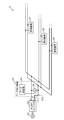
- FIG. 1 is a configuration diagram showing an example of the photovoltaic power generation system 1 according to the first embodiment.
- the photovoltaic power generation system 1 includes a solar panel 41, storage batteries 54, 55 and 56, DC / DC converters 51, 52 and 53, and a power conditioner (power conditioner) 60.
- the solar panel 41 generates electricity by sunlight and generates DC power.
- the DC power generated by the solar panel 41 is supplied to the power conditioner 60.
- the storage battery 54 stores the DC power from the DC / DC converter 51
- the storage battery 55 stores the DC power from the DC / DC converter 52
- the storage battery 56 stores the DC power from the DC / DC converter 53.
- the storage batteries 54, 55, and 56 may be mounted on an electric vehicle, an electric bicycle, or the like, or may be used for supplying power to household electric appliances or the like.
- the DC / DC converters 51, 52, and 53 are voltage converters that boost or step down the DC voltage of the supplied DC power and output it.
- the DC / DC converter 51 boosts or lowers the DC power supplied from the power conditioner 60 and outputs it to the storage battery 54.
- the DC / DC converter 52 boosts or lowers the DC power supplied from the power conditioner 60 and outputs it to the storage battery 55.
- the DC / DC converter 53 boosts or lowers the DC power supplied from the power conditioner 60 and outputs it to the storage battery 56.
- the power conditioner 60 has a function of converting DC power supplied from the solar panel 41 into AC power. Further, the power conditioner 60 has a function of supplying DC power supplied from the solar panel 41 to a storage battery or the like without converting it into AC power.
- the power conditioner 60 includes a DC / DC converter 61, an inverter 62, and an arc detection device 10.
- the DC / DC converter 61 boosts or lowers the DC power supplied from the solar panel 41 and outputs it to the DC / DC converters 51, 52 and 53 and the inverter 62. Since DC power is output from the DC / DC converter 61, the DC / DC converter 61 can be regarded as a DC power supply. That is, the DC / DC converter 61 is an example of a DC power supply.
- the DC / DC converter 61 has a positive electrode and a negative electrode, and the wiring 110 is connected to the positive electrode and the wiring 120 is connected to the negative electrode.
- Wiring 110 and 120 connect the DC / DC converter 61 and the DC / DC converters 51, 52 and 53.
- the wiring 110 is an example of the first wiring for connecting the positive electrode of the DC / DC converter 61 and a plurality of devices.
- the wiring 120 is an example of the second wiring that connects the negative electrode of the DC / DC converter 61 and a plurality of devices.
- the DC / DC converters 51, 52 and 53 are examples of a plurality of devices connected to the DC / DC converter 61 via the wirings 110 and 120.
- the wiring 110 is wiring that branches from the positive electrode of the DC / DC converter 61 to each of the DC / DC converters 51, 52, and 53.
- the point at which the positive electrode of the DC / DC converter 61 in the wiring 110 branches to the DC / DC converters 51, 52, and 53 is defined as the branch point N3.
- the path before branching connecting the branch point N3 and the positive electrode of the DC / DC converter 61 is the path 110a
- the path after branching connecting the branch point N3 and the DC / DC converter 51 is the path 110c
- the branch point is defined as the path 110c.
- the post-branch route connecting N3 and the DC / DC converter 52 is referred to as the path 110d
- the post-branch route connecting the branch point N3 and the DC / DC converter 53 is referred to as the path 110b.
- the wiring 120 is a wiring that branches from the negative electrode of the DC / DC converter 61 to each of the DC / DC converters 51, 52, and 53.
- the point at which the negative electrode of the DC / DC converter 61 in the wiring 120 branches to the DC / DC converters 51, 52, and 53 is defined as the branch point N4.
- the path before branching connecting the branch point N4 and the negative electrode of the DC / DC converter 61 is set as the path 120a
- the path after branching connecting the branch point N4 and the DC / DC converter 51 is set as the path 120c.
- the post-branch route connecting N4 and the DC / DC converter 52 is referred to as the path 120d
- the post-branch route connecting the branch point N4 and the DC / DC converter 53 is referred to as the path 120b.
- the inverter 62 converts the DC power supplied from the DC / DC converter 61 into AC power and outputs it.
- the inverter 62 employs, for example, an MPPT (Maximum Power Point Tracking) method, and adjusts the current and voltage of the DC power supplied from the DC / DC converter 61 to values that maximize the power, respectively.
- MPPT Maximum Power Point Tracking
- the inverter 62 converts DC power into AC power having a voltage of 100 V and a frequency of 50 Hz or 60 Hz.
- the AC power is used in household electric appliances and the like.
- Wiring 110 and 120 are branch wirings, and arcs may be generated for each of the pre-branch path and the post-branch plurality of paths of the branch wiring. If arc detection means are provided for each of the pre-branch route and the plurality of post-branch routes, arcs can be detected for each of the pre-branch route and the post-branch route, but the system becomes large and the system becomes large. In addition, the cost will be increased.
- the arc detection device 10 is used.
- the arc detection device 10 includes a voltage detection unit 20 and an arc determination unit 30.
- the voltage detection unit 20 is connected between the wiring 110 and the wiring 120, and detects the voltage between the wiring 110 and 120.
- the voltage detection unit 20 is, for example, a voltmeter.
- the voltage detected by the voltage detection unit 20 is input to the arc determination unit 30.
- the voltage detection unit 20 is connected between the path 110a in the wiring 110 and the path 120a in the wiring 120 (in other words, the node N1 is a node on the path 110a and the node N2 is a node on the path 120a.
- node N1 may be a node on route 110b, 110c or 110d
- node N2 may be a node on route 120b, 120c or 120d.
- the arc determination unit 30 is realized by, for example, a microcomputer (microcontroller).
- the microcomputer is a ROM, a RAM in which a program is stored, a processor (CPU: Central Processing Unit) that executes a program, a timer, an A / D converter, a semiconductor integrated circuit having a D / A converter, and the like.
- the arc determination unit 30 may be realized by hardware by a dedicated electronic circuit composed of an A / D converter, a logic circuit, a gate array, a D / A converter, and the like.
- the arc determination unit 30 determines the occurrence of an arc based on the voltage detected by the voltage detection unit 20. For example, the arc determination unit 30 determines the occurrence of an arc in the wiring 110 or 120 by frequency-analyzing the voltage detected by the voltage detection unit 20. The voltage on which the high frequency component generated by the generation of the arc is superimposed includes the frequency component caused by the arc, and the generation of the arc can be determined by detecting the frequency component.
- the arc determination unit 30 determines that an arc has occurred, it can be seen that an arc has occurred somewhere in the wirings 110 and 120. That is, only one voltage detection unit 20 (for example, a voltmeter) can detect an arc in the branch wiring (here, wirings 110 and 120).
- the arc can be detected by using one voltage detection unit 20 regardless of where the arc is generated in the pre-branch path and the plurality of post-branch paths in the wirings 110 and 120.
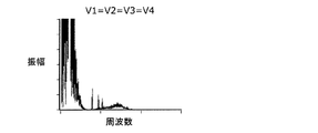
- FIG. 2 is a diagram for explaining that the voltage between the paths before branching and between the paths after branching is the same.
- FIG. 2 shows the voltage V1 between the paths 110a and 120a, the voltage V2 between the paths 110c and 120c, the voltage V3 between the paths 110d and 120d, and the paths 110b and 120b when an arc is generated in the path 110a.
- It is a figure which shows the frequency spectrum of the voltage V4 between.
- the frequency spectra for the voltages V1, V2, V3 and V4 are all substantially the same as the frequency spectra shown in FIG.
- the routes before and after branching are measured between the routes before branching (for example, between routes 110a and 120a) or between the routes after branching (for example, between routes 110b and 120b), the routes before and after branching. This is because the voltage between the wiring 110 and the wiring 120 is substantially the same without being affected by the branching of the wiring even between the paths (for example, between the paths 110a and 120b).
- the arc can be detected by using one voltage detection unit 20.
- the arc detection device 10 connects the positive electrode of the DC power supply (for example, DC / DC converter 61) and a plurality of devices (for example, DC / DC converters 51, 52, 53).
- the first wiring for example, wiring 110
- the DC power supply branches to each of the plurality of devices.
- a voltage detection unit 20 that is connected to the second wiring (for example, wiring 120) and detects the voltage between the first wiring and the second wiring, and the arc based on the voltage detected by the voltage detection unit 20.
- An arc determination unit 30 for determining generation is provided.
- the voltage detection unit 20 that detects the voltage between the first wiring and the second wiring can detect the voltage on which the high-frequency component generated by the generation of the arc is superimposed, and detects the arc based on the voltage. can. That is, it is possible to detect an arc generated in the branch wiring without providing arc detection means for each of the path before branching and the plurality of paths after branching of the branch wiring.
- the arc generated in the branch wiring can be easily detected by using one voltage detection unit 20.
- the DC / DC converter 61 and the inverter 62 are stopped or a breaker or the like (not shown) provided in each wiring is operated based on the detection result. The current flowing through the wiring can be cut off.
- the power conditioner 60 includes an arc detection device 10 and a converter (for example, an inverter 62) that converts the output power of a DC power supply.
- a converter for example, an inverter 62
- FIG. 3 is a configuration diagram showing an example of the indoor wiring system 2 according to the second embodiment. Note that FIG. 3 also shows a system power supply 43 connected to the indoor wiring system 2.
- the grid power supply 43 is a power supply that supplies AC power generated at a power plant or the like.
- the indoor wiring system 2 includes an AC / DC converter 42, wirings 111 and 121, lighting fixtures 57, 58 and 59, and an arc detection device 10.
- the AC / DC converter 42, wirings 111 and 121, lighting fixtures 57, 58 and 59, and the arc detection device 10 are installed indoors in a facility such as a detached house, an apartment house, a building or a factory.
- the AC / DC converter 42 is a power converter in which AC power is supplied from the system power supply 43, and the supplied AC power is converted into DC power and output. Since DC power is output from the AC / DC converter 42, the AC / DC converter 42 can be regarded as a DC power supply.
- the AC / DC converter 42 converts the AC power supplied from the system power supply 43 into DC power and outputs it to the lighting fixtures 57, 58 and 59.
- the AC / DC converter 42 has a positive electrode and a negative electrode, and the wiring 111 is connected to the positive electrode and the wiring 121 is connected to the negative electrode.
- Wiring 111 and 121 connect the AC / DC converter 42 and the lighting fixtures 57, 58 and 59.
- the wiring 111 is an example of the first wiring that connects the positive electrode of the AC / DC converter 42 and a plurality of devices.
- the wiring 121 is an example of the second wiring that connects the negative electrode of the AC / DC converter 42 and a plurality of devices.
- the luminaires 57, 58 and 59 are examples of a plurality of devices connected to the AC / DC converter 42 via the wirings 111 and 121, respectively.
- the wiring 111 is a wiring that branches from the positive electrode of the AC / DC converter 42 to each of the lighting fixtures 57, 58, and 59, as in the wiring 110 in the first embodiment.
- the wiring 121 is a wiring that branches from the negative electrode of the AC / DC converter 42 to each of the lighting fixtures 57, 58, and 59, as in the wiring 120 in the first embodiment.
- the plurality of devices are not limited to lighting fixtures, and are not particularly limited as long as they are devices installed indoors.
- the plurality of devices may be speakers, microphones, or the like.
- Wiring 111 and 121 are branch wirings, and arcs may be generated for each of the pre-branch path and the post-branch plurality of paths of the branch wiring. If arc detection means are provided for each of the pre-branch route and the plurality of post-branch routes, arcs can be detected for each of the pre-branch route and the post-branch route, but the system becomes large and the system becomes large. In addition, the cost will be increased.
- the arc detection device 10 is used.
- the arc detection device 10 includes a voltage detection unit 20 and an arc determination unit 30.
- the voltage detection unit 20 is connected between the wiring 111 and the wiring 121, and detects the voltage between the wiring 111 and 121.
- the arc determination unit 30 determines the occurrence of an arc based on the voltage detected by the voltage detection unit 20. Since the arc determination unit 30 has the same function as that in the first embodiment, the description thereof will be omitted.
- the arc can be detected by using one voltage detection unit 20 regardless of where the arc is generated in the pre-branch path and the plurality of post-branch paths in the wirings 111 and 121.
- the indoor wiring system 2 includes an arc detection device 10, a first wiring (for example, wiring 111), a second wiring (for example, wiring 121), and a plurality of indoor wiring systems installed indoors.
- Equipment eg, lighting fixtures 57, 58 and 59).
- the arc detection device 10 may be applied to the indoor wiring system 2, and the indoor wiring system 2 capable of easily detecting the arc generated in the branch wiring can be provided.
- the arc detection device is applied to a photovoltaic power generation system (specifically, a power conditioner) and an indoor wiring system
- a photovoltaic power generation system specifically, a power conditioner
- an indoor wiring system specifically, a power conditioner
- the application example is not limited to these.
- Another application example of the arc detection device according to the present invention that is, the arc detection device that can easily detect the arc generated in the branch wiring
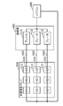
- FIG. 4 is a diagram for explaining an application example of the arc detection device according to the present invention.
- the arc detection device is applied to, for example, each component in a system in which DC power supplied from a solar panel 310 via wiring is converted into AC power by a power conditioner 500.
- a plurality (for example, three) of solar panels 310 connected in series by one wiring 600 (string) are arranged side by side to form a solar cell array 300.
- the plurality of wirings 600 are grouped by the junction box 400 and connected to the power conditioner 500.
- the DC power supply is the solar panel 310
- the first wiring is the wiring 600 connected to the positive electrode of the solar panel 310
- the second wiring is the wiring 600 connected to the negative electrode of the solar panel 310.
- the wiring 600 is branched in the power conditioner 500.
- a breaker 410 is provided for each wiring 600, and here, a breaker 410 is provided in the junction box 400.
- the breaker 410 does not have to be provided in the junction box 400.
- the breaker 410 may be provided between the junction box 400 and the solar cell array 300, or may be provided between the junction box 400 and the power conditioner 500 without being provided for each wiring 600.
- the solar panel 310 has, for example, a solar panel accessory module 320 that converts a signal output from the solar panel 310.
- the solar panel accessory module 320 is, for example, a DC / DC converter that optimizes the amount of power generation for each solar panel 310.
- the solar panel 310 does not have to have the module attached to the solar panel 320.
- the breaker 410 may be provided with an arc detection device.
- the breaker 410 cuts off the current flowing through the wiring 600 when it is determined that an abnormality has occurred.
- the solar panel 310 or the module attached to the solar panel 320 may include an arc detection device.
- the solar panel 310 or the module attached to the solar panel 320 stops the output to the wiring 600 when it is determined that an arc has been generated.
- the junction box 400 may be provided with an arc detection device. When it is determined that an arc has been generated, the junction box 400 cuts off the current flowing through the wiring 600, for example, via a breaker 410 or the like.
- the arc detection device according to the present invention is not limited to these, and can be applied to all systems that require arc detection.
- the breaker 410 may be provided with an arc detection device, and when it is determined that an arc has been generated, the current flowing through the first wiring and the second wiring may be cut off.
- the solar panel 310 may include an arc detection device and generate electricity by sunlight.
- the solar panel accessory module 320 may include an arc detection device and convert the signal output from the solar panel 310.
- the junction box 400 may include an arc detection device and may connect the solar panel 310 and the power conditioner 500.
- the arc determination unit included in the arc detection device may be realized by software in a general-purpose computer such as a personal computer.
- Photovoltaic power generation system Indoor wiring system 10
- Arc detection device 20
- Voltage detection unit 30
- Arc judgment unit 41, 310
- Solar panel 42
- AC / DC converter 43
- System power supply 51, 52, 53, 61
- DC / DC converter 54, 55, 56
- Lighting equipment 60
- Wiring 110a, 110b, 110c, 110d, 120a, 120b, 120c, 120d Route 300
- Solar cell array 320
- Solar panel included Module 400
- Junction Box 410 Breaker N1, N2 Node N3, N4 Branch Point V1, V2, V3, V4 Voltage
Abstract
アーク検出装置(10)は、DC/DCコンバータ(61)の正極と複数のDC/DCコンバータ(51、52及び53)とを接続し、DC/DCコンバータ(61)の正極から複数のDC/DCコンバータ(51、52及び53)のそれぞれへと分岐している第1配線(110)と、DC/DCコンバータ(61)の負極と複数のDC/DCコンバータ(51、52及び53)とを接続しDC/DCコンバータ(61)の負極から複数のDC/DCコンバータ(51、52及び53)のそれぞれへと分岐している第2配線(120)との間に接続され、第1配線(110)及び第2配線(120)間の電圧を検出する電圧検出部(20)と、電圧検出部(20)により検出された電圧に基づいて、アークの発生を判定するアーク判定部(30)と、を備える。
Description
本発明は、アーク検出装置、パワーコンディショナ、屋内配線システム、ブレーカ、太陽光パネル、太陽光パネル付属モジュール及び接続箱に関する。
従来、PV(Photo Voltaic)パネル(太陽光パネル)等から配線を介して供給される直流電力をインバータ等の機器で交流電力に変換するシステムが知られている。このような配線は、外的要因又は経年劣化等によって損傷又は破断を引き起こすことが報告されている。このような配線の損傷等に起因してアーク(つまりアーク放電)が発生する場合がある。そこで、アークを検出するためのアーク検出手段が提案されている(例えば、特許文献1)。
今後、1つのシステム内において複数の機器が設けられ、1つの直流電源から複数の機器のそれぞれへと分岐している配線(分岐配線と呼ぶ)を介して複数の機器に電力を供給することが想定される。このとき、分岐配線の分岐前の経路と分岐後の複数の経路のそれぞれについてアークが発生する場合がある。分岐配線の分岐前の経路と分岐後の複数の経路のそれぞれにアーク検出手段を設ければ、分岐前の経路と分岐後の複数の経路のそれぞれについてアークを検出することができるが、システムが大型化し、また、高コスト化する。
そこで、本発明は、分岐配線において発生するアークを容易に検出できるアーク検出装置等を提供する。
本発明に係るアーク検出装置の一態様は、直流電源の正極と複数の機器とを接続し、前記直流電源から前記複数の機器のそれぞれへと分岐している第1配線と、前記直流電源の負極と前記複数の機器とを接続し前記直流電源から前記複数の機器のそれぞれへと分岐している第2配線との間に接続され、前記第1配線及び前記第2配線間の電圧を検出する電圧検出部と、前記電圧検出部により検出された電圧に基づいて、アークの発生を判定するアーク判定部と、を備える。
本発明に係るパワーコンディショナの一態様は、上記のアーク検出装置と、前記直流電源の出力電力を変換する変換器と、を備える。
本発明に係る屋内配線システムの一態様は、上記のアーク検出装置と、前記第1配線と、前記第2配線と、屋内に設置された前記複数の機器と、を備える。
本発明に係るブレーカの一態様は、上記のアーク検出装置を備え、アークが発生したと判定された場合に、前記第1配線及び前記第2配線に流れる電流を遮断する。
本発明に係る太陽光パネルの一態様は、上記のアーク検出装置を備え、太陽光により発電する。
本発明に係る太陽光パネル付属モジュールの一態様は、上記のアーク検出装置を備え、太陽光パネルから出力される信号の変換を行う。
本発明に係る接続箱の一態様は、上記のアーク検出装置を備え、太陽光パネルとパワーコンディショナとを接続する。
本発明の一態様によれば、分岐配線において発生するアークを容易に検出できる。
以下、本発明の実施の形態について、図面を参照しながら説明する。以下に説明する実施の形態は、いずれも本発明の一具体例を示すものである。したがって、以下の実施の形態で示される数値、形状、材料、構成要素、構成要素の配置位置及び接続形態等は、一例であって本発明を限定する主旨ではない。
なお、各図は、模式図であり、必ずしも厳密に図示されたものではない。また、各図において、実質的に同一の構成に対しては同一の符号を付しており、重複する説明は省略又は簡略化する。
(実施の形態1)
図1は、実施の形態1に係る太陽光発電システム1の一例を示す構成図である。
図1は、実施の形態1に係る太陽光発電システム1の一例を示す構成図である。
太陽光発電システム1は、太陽光パネル41、蓄電池54、55及び56、DC/DCコンバータ51、52及び53並びにパワーコンディショナ(パワコン)60を備える。
太陽光パネル41は、太陽光により発電し直流電力を発生する。太陽光パネル41で発生した直流電力はパワコン60に供給される。
蓄電池54はDC/DCコンバータ51からの直流電力を蓄電し、蓄電池55はDC/DCコンバータ52からの直流電力を蓄電し、蓄電池56はDC/DCコンバータ53からの直流電力を蓄電する。例えば、蓄電池54、55及び56は、電気自動車又は電動自転車等に搭載されてもよいし、家庭用電気機器等への電力供給のために用いられてもよい。
DC/DCコンバータ51、52及び53は、供給された直流電力の直流電圧を昇圧又は降圧して出力する電圧変換器である。DC/DCコンバータ51は、パワコン60から供給された直流電力を昇圧又は降圧して、蓄電池54に出力する。DC/DCコンバータ52は、パワコン60から供給された直流電力を昇圧又は降圧して、蓄電池55に出力する。DC/DCコンバータ53は、パワコン60から供給された直流電力を昇圧又は降圧して、蓄電池56に出力する。
パワコン60は、太陽光パネル41から供給される直流電力を交流電力に変換する機能を有する。また、パワコン60は、太陽光パネル41から供給される直流電力を交流電力に変換せずに蓄電池等に供給する機能を有する。パワコン60は、DC/DCコンバータ61、インバータ62及びアーク検出装置10を備える。
DC/DCコンバータ61は、太陽光パネル41から供給された直流電力を昇圧又は降圧して、DC/DCコンバータ51、52及び53並びにインバータ62へ出力する。DC/DCコンバータ61からは直流電力が出力されるため、DC/DCコンバータ61は直流電源とみなすことができる。すなわち、DC/DCコンバータ61は、直流電源の一例である。DC/DCコンバータ61は正極と負極を有し、正極には配線110が接続され、負極には配線120が接続される。
配線110及び120は、DC/DCコンバータ61とDC/DCコンバータ51、52及び53とを接続する。配線110は、DC/DCコンバータ61の正極と複数の機器とを接続する第1配線の一例である。配線120は、DC/DCコンバータ61の負極と複数の機器とを接続する第2配線の一例である。DC/DCコンバータ51、52及び53は、配線110及び120を介してDC/DCコンバータ61に接続される複数の機器の一例である。
配線110は、DC/DCコンバータ61の正極からDC/DCコンバータ51、52及び53のそれぞれへと分岐している配線である。配線110におけるDC/DCコンバータ61の正極からDC/DCコンバータ51、52及び53へ分岐する点を分岐点N3とする。
配線110において、分岐点N3とDC/DCコンバータ61の正極とを結ぶ分岐前の経路を経路110aとし、分岐点N3とDC/DCコンバータ51とを結ぶ分岐後の経路を経路110cとし、分岐点N3とDC/DCコンバータ52とを結ぶ分岐後の経路を経路110dとし、分岐点N3とDC/DCコンバータ53とを結ぶ分岐後の経路を経路110bとする。
配線120は、DC/DCコンバータ61の負極からDC/DCコンバータ51、52及び53のそれぞれへと分岐している配線である。配線120におけるDC/DCコンバータ61の負極からDC/DCコンバータ51、52及び53へ分岐する点を分岐点N4とする。
配線120において、分岐点N4とDC/DCコンバータ61の負極とを結ぶ分岐前の経路を経路120aとし、分岐点N4とDC/DCコンバータ51とを結ぶ分岐後の経路を経路120cとし、分岐点N4とDC/DCコンバータ52とを結ぶ分岐後の経路を経路120dとし、分岐点N4とDC/DCコンバータ53とを結ぶ分岐後の経路を経路120bとする。
インバータ62は、DC/DCコンバータ61から供給された直流電力を交流電力に変換して出力する。インバータ62は、例えばMPPT(Maximum Power Point Tracking)方式を採用しており、DC/DCコンバータ61から供給される直流電力の電流及び電圧を、それぞれ電力が最大となる値に調整する。例えば、インバータ62は、直流電力を電圧100V、周波数50Hz又は60Hzの交流電力に変換する。当該交流電力は、家庭用電気機器等で使用される。
配線110及び120は分岐配線であり、分岐配線の分岐前の経路と分岐後の複数の経路のそれぞれについてアークが発生する場合がある。分岐前の経路と分岐後の複数の経路のそれぞれにアーク検出手段を設ければ、分岐前の経路と分岐後の複数の経路のそれぞれについてアークを検出することができるが、システムが大型化し、また、高コスト化する。
そこで、分岐配線(ここでは配線110及び120)において発生するアークを容易に検出するために、アーク検出装置10が用いられる。
アーク検出装置10は、電圧検出部20及びアーク判定部30を備える。
電圧検出部20は、配線110と配線120との間に接続され、配線110及び120間の電圧を検出する。電圧検出部20は、例えば電圧計である。電圧検出部20で検出された電圧は、アーク判定部30に入力される。なお、電圧検出部20は、配線110における経路110aと配線120における経路120aとの間に接続されている(言い換えると、ノードN1は経路110a上のノードであり、ノードN2は経路120a上のノードである)が、これに限らない。例えば、ノードN1は、経路110b、110c又は110d上のノードであってもよく、ノードN2は、経路120b、120c又は120d上のノードであってもよい。
アーク判定部30は、例えばマイコン(マイクロコントローラ)により実現される。マイコンは、プログラムが格納されたROM、RAM、プログラムを実行するプロセッサ(CPU:Central Processing Unit)、タイマ、A/D変換器及びD/A変換器等を有する半導体集積回路等である。なお、アーク判定部30は、A/D変換器、論理回路、ゲートアレイ及びD/A変換器等で構成される専用の電子回路によってハードウェア的に実現されてもよい。
アーク判定部30は、電圧検出部20により検出された電圧に基づいて、アークの発生を判定する。例えば、アーク判定部30は、電圧検出部20により検出された電圧を周波数分析することで配線110又は120におけるアークの発生を判定する。アークの発生により生じる高周波成分が重畳した電圧には、アークに起因する周波数成分が含まれており、当該周波数成分を検出することでアークの発生を判定することができる。アーク判定部30がアークが発生したと判定した場合、配線110及び120のどこかにアークが発生したことがわかる。つまり、1つの電圧検出部20(例えば電圧計)のみで、分岐配線(ここでは配線110及び120)におけるアークを検出できる。
配線110及び120における分岐前の経路及び分岐後の複数の経路のどこでアークが発生しても1つの電圧検出部20を用いてアークを検出できることを、図2を用いて説明する。
図2は、分岐前の経路間及び分岐後の経路間のいずれの電圧も同じであることを説明するための図である。図2は、経路110aにおいてアークが発生したときの、図1における経路110a及び120a間の電圧V1、経路110c及び120c間の電圧V2、経路110d及び120d間の電圧V3、並びに、経路110b及び120b間の電圧V4の周波数スペクトルを示す図である。電圧V1、V2、V3及びV4についてのそれぞれの周波数スペクトルは、図2に示される周波数スペクトルのように全て略同じになっている。電圧を計測する箇所が、分岐前の経路間(例えば経路110a及び120a間)であっても、分岐後の経路間(例えば経路110b及び120b間)であっても、分岐前と分岐後の経路間(例えば経路110a及び120b間)であっても、配線110及び配線120間の電圧は、配線が分岐していることの影響を受けず略同じとなるためである。
このため、配線110及び120における分岐前の経路及び分岐後の複数の経路のどこでアークが発生しても1つの電圧検出部20を用いてアークを検出できる。
以上説明したように、本実施の形態に係るアーク検出装置10は、直流電源(例えばDC/DCコンバータ61)の正極と複数の機器(例えばDC/DCコンバータ51、52及び53)とを接続し、直流電源から複数の機器のそれぞれへと分岐している第1配線(例えば配線110)と、直流電源の負極と複数の機器とを接続し直流電源から複数の機器のそれぞれへと分岐している第2配線(例えば配線120)との間に接続され、第1配線及び第2配線間の電圧を検出する電圧検出部20と、電圧検出部20により検出された電圧に基づいて、アークの発生を判定するアーク判定部30と、を備える。
これによれば、第1配線及び第2配線の分岐前の経路と分岐後の複数の経路のそれぞれ(例えば、経路110a、110b、110c、110d、120a、120b、120c及び120d)のどこでアークが発生したとしても、第1配線及び第2配線間の電圧を検出する電圧検出部20によって、アークの発生により生じる高周波成分が重畳した電圧を検出することができ、当該電圧に基づいてアークを検出できる。つまり、分岐配線の分岐前の経路と分岐後の複数の経路のそれぞれにアーク検出手段を設けなくても、分岐配線において発生するアークを検出できる。すなわち、システムを大型化したり、高コスト化したりしなくてもよく、1つの電圧検出部20を用いて、分岐配線において発生するアークを容易に検出できる。例えば、アークが検出された場合、当該検出結果に基づいて、DC/DCコンバータ61及びインバータ62を停止したり、各配線に設けられたブレーカ等(図示せず)を操作したりして、各配線を流れる電流を遮断することができる。
本実施の形態に係るパワコン60は、アーク検出装置10と、直流電源の出力電力を変換する変換器(例えばインバータ62)と、を備える。
これによれば、分岐配線において発生するアークを容易に検出できるパワコン60を提供できる。
(実施の形態2)
実施の形態1では、アーク検出装置が太陽光発電システム(具体的にはパワコン)に備えられる例について説明したが、アーク検出装置は、屋内配線システムに備えられてもよい。これについて、図3を用いて説明する。
実施の形態1では、アーク検出装置が太陽光発電システム(具体的にはパワコン)に備えられる例について説明したが、アーク検出装置は、屋内配線システムに備えられてもよい。これについて、図3を用いて説明する。
図3は、実施の形態2に係る屋内配線システム2の一例を示す構成図である。なお、図3には、屋内配線システム2に接続された系統電源43も示している。
系統電源43は、発電所等で生成された交流電力を供給する電源である。
屋内配線システム2は、AC/DCコンバータ42、配線111及び121、照明器具57、58及び59並びにアーク検出装置10を備える。AC/DCコンバータ42、配線111及び121、照明器具57、58及び59並びにアーク検出装置10は、戸建て、集合住宅、ビル又は工場等の施設の屋内に設置される。
AC/DCコンバータ42は、系統電源43から交流電力が供給され、供給された交流電力を直流電力に変換して出力する電力変換器である。AC/DCコンバータ42からは直流電力が出力されるため、AC/DCコンバータ42を直流電源とみなすことができる。
AC/DCコンバータ42は、系統電源43から供給された交流電力を直流電力に変換して、照明器具57、58及び59に出力する。AC/DCコンバータ42は正極と負極を有し、正極には配線111が接続され、負極には配線121が接続される。
配線111及び121は、AC/DCコンバータ42と照明器具57、58及び59とを接続する。配線111は、AC/DCコンバータ42の正極と複数の機器とを接続する第1配線の一例である。配線121は、AC/DCコンバータ42の負極と複数の機器とを接続する第2配線の一例である。照明器具57、58及び59は、それぞれ、配線111及び121を介してAC/DCコンバータ42に接続される複数の機器の一例である。
配線111は、実施の形態1における配線110と同じように、AC/DCコンバータ42の正極から照明器具57、58及び59のそれぞれへと分岐している配線である。配線121は、実施の形態1における配線120と同じように、AC/DCコンバータ42の負極から照明器具57、58及び59のそれぞれへと分岐している配線である。
なお、複数の機器は照明器具に限らず、屋内に設置される機器であれば特に限定されない。例えば、複数の機器は、スピーカ又はマイク等であってもよい。
配線111及び121は分岐配線であり、分岐配線の分岐前の経路と分岐後の複数の経路のそれぞれについてアークが発生する場合がある。分岐前の経路と分岐後の複数の経路のそれぞれにアーク検出手段を設ければ、分岐前の経路と分岐後の複数の経路のそれぞれについてアークを検出することができるが、システムが大型化し、また、高コスト化する。
そこで、分岐配線(ここでは配線111及び121)において発生するアークを容易に検出するために、アーク検出装置10が用いられる。
アーク検出装置10は、電圧検出部20及びアーク判定部30を備える。
電圧検出部20は、配線111と配線121との間に接続され、配線111及び121間の電圧を検出する。
アーク判定部30は、電圧検出部20により検出された電圧に基づいて、アークの発生を判定する。アーク判定部30は、実施の形態1におけるものと同じ機能を有するため説明は省略する。
屋内配線システム2においても、電圧を計測する箇所が、分岐前の経路間であっても、分岐後の経路間であっても、分岐前と分岐後の経路間であっても、配線111及び配線121間の電圧は略同じとなるため、配線111及び121における分岐前の経路及び分岐後の複数の経路のどこでアークが発生しても1つの電圧検出部20を用いてアークを検出できる。
以上説明したように、本実施の形態に係る屋内配線システム2は、アーク検出装置10と、第1配線(例えば配線111)と、第2配線(例えば配線121)と、屋内に設置された複数の機器(例えば照明器具57、58及び59)と、を備える。
このように、アーク検出装置10を屋内配線システム2に適用してもよく、分岐配線において発生するアークを容易に検出できる屋内配線システム2を提供できる。
(その他の実施の形態)
以上、実施の形態に係るアーク検出装置等について説明したが、本発明は、上記実施の形態に限定されるものではない。
以上、実施の形態に係るアーク検出装置等について説明したが、本発明は、上記実施の形態に限定されるものではない。
例えば、上記実施の形態では、アーク検出装置が太陽光発電システム(具体的にはパワコン)及び屋内配線システムに適用される例について説明したが、適用例はこれらに限らない。本発明に係るアーク検出装置(つまり、分岐配線において発生するアークを容易に検出できるアーク検出装置)の他の適用例について図4を用いて説明する。
図4は、本発明に係るアーク検出装置の適用例を説明するための図である。
本発明に係るアーク検出装置は、例えば、太陽光パネル310から配線を介して供給される直流電力を、パワコン500で交流電力に変換するシステムにおける各構成要素に適用される。ここでは、複数(例えば3つ)の太陽光パネル310が1つの配線600(ストリング)によって直列に接続されたものが複数(例えば3つ)並べられて、太陽電池アレイ300を形成している。複数の配線600は、接続箱400によってまとめられて、パワコン500へ接続される。直流電源は太陽光パネル310であり、第1配線は太陽光パネル310の正極に接続された配線600であり、第2配線は太陽光パネル310の負極に接続された配線600である。配線600は、パワコン500内において分岐している。
例えば、配線600毎にブレーカ410が設けられており、ここでは、接続箱400内にブレーカ410が設けられている。なお、ブレーカ410は、接続箱400内に設けられなくてもよい。例えば、ブレーカ410は、接続箱400と太陽電池アレイ300との間に設けられていてもよいし、配線600毎に設けられず接続箱400とパワコン500との間に設けられていてもよい。
太陽光パネル310は、例えば、太陽光パネル310から出力される信号の変換を行う太陽光パネル付属モジュール320を有する。太陽光パネル付属モジュール320は、例えば、太陽光パネル310毎の発電量を最適化するDC/DCコンバータである。なお、太陽光パネル310は、太陽光パネル付属モジュール320を有していなくてもよい。
例えば、ブレーカ410がアーク検出装置を備えていてもよい。ブレーカ410は、異常が発生したと判定された場合に、配線600に流れる電流を遮断する。
例えば、太陽光パネル310又は太陽光パネル付属モジュール320がアーク検出装置を備えていてもよい。太陽光パネル310又は太陽光パネル付属モジュール320は、アークが発生したと判定された場合に、配線600への出力を停止する。
また、例えば、接続箱400がアーク検出装置を備えていてもよい。接続箱400は、アークが発生したと判定された場合に、例えばブレーカ410等を介して、配線600に流れる電流を遮断する。
なお、本発明に係るアーク検出装置は、これらに限らず、アークの検出が必要なシステム全般に適用できる。
このように、ブレーカ410は、アーク検出装置を備え、アークが発生したと判定された場合に、第1配線及び第2配線に流れる電流を遮断してもよい。また、太陽光パネル310は、アーク検出装置を備え、太陽光により発電してもよい。また、太陽光パネル付属モジュール320は、アーク検出装置を備え、太陽光パネル310から出力される信号の変換を行ってもよい。また、接続箱400は、アーク検出装置を備え、太陽光パネル310とパワコン500とを接続してもよい。
例えば、アーク検出装置が備えるアーク判定部は、パーソナルコンピュータ等の汎用コンピュータにおいてソフトウェア的に実現されてもよい。
その他、各実施の形態に対して当業者が思いつく各種変形を施して得られる形態や、本発明の趣旨を逸脱しない範囲で各実施の形態における構成要素及び機能を任意に組み合わせることで実現される形態も本発明に含まれる。
1 太陽光発電システム
2 屋内配線システム
10 アーク検出装置
20 電圧検出部
30 アーク判定部
41、310 太陽光パネル
42 AC/DCコンバータ
43 系統電源
51、52、53、61 DC/DCコンバータ
54、55、56 蓄電池
57、58、59 照明器具
60、500 パワコン
62 インバータ
110、111、120、121、600 配線
110a、110b、110c、110d、120a、120b、120c、120d 経路
300 太陽電池アレイ
320 太陽光パネル付属モジュール
400 接続箱
410 ブレーカ
N1、N2 ノード
N3、N4 分岐点
V1、V2、V3、V4 電圧
2 屋内配線システム
10 アーク検出装置
20 電圧検出部
30 アーク判定部
41、310 太陽光パネル
42 AC/DCコンバータ
43 系統電源
51、52、53、61 DC/DCコンバータ
54、55、56 蓄電池
57、58、59 照明器具
60、500 パワコン
62 インバータ
110、111、120、121、600 配線
110a、110b、110c、110d、120a、120b、120c、120d 経路
300 太陽電池アレイ
320 太陽光パネル付属モジュール
400 接続箱
410 ブレーカ
N1、N2 ノード
N3、N4 分岐点
V1、V2、V3、V4 電圧
Claims (7)
- 直流電源の正極と複数の機器とを接続し、前記直流電源から前記複数の機器のそれぞれへと分岐している第1配線と、前記直流電源の負極と前記複数の機器とを接続し前記直流電源から前記複数の機器のそれぞれへと分岐している第2配線との間に接続され、前記第1配線及び前記第2配線間の電圧を検出する電圧検出部と、
前記電圧検出部により検出された電圧に基づいて、アークの発生を判定するアーク判定部と、を備える
アーク検出装置。 - 請求項1に記載のアーク検出装置と、
前記直流電源の出力電力を変換する変換器と、を備える
パワーコンディショナ。 - 請求項1に記載のアーク検出装置と、
前記第1配線と、
前記第2配線と、
屋内に設置された前記複数の機器と、を備える
屋内配線システム。 - 請求項1に記載のアーク検出装置を備え、
アークが発生したと判定された場合に、前記第1配線及び前記第2配線に流れる電流を遮断する
ブレーカ。 - 請求項1に記載のアーク検出装置を備え、
太陽光により発電する
太陽光パネル。 - 請求項1に記載のアーク検出装置を備え、
太陽光パネルから出力される信号の変換を行う
太陽光パネル付属モジュール。 - 請求項1に記載のアーク検出装置を備え、
太陽光パネルとパワーコンディショナとを接続する
接続箱。
Priority Applications (4)
| Application Number | Priority Date | Filing Date | Title |
|---|---|---|---|
| JP2022505986A JPWO2021182263A1 (ja) | 2020-03-11 | 2021-03-03 | |
| EP21767679.0A EP4120496A4 (en) | 2020-03-11 | 2021-03-03 | ARC DETECTION DEVICE, POWER CONDITIONER, INTERIOR WIRING SYSTEM, CIRCUIT BREAKER, SOLAR PANEL, SOLAR PANEL ATTACHED MODULE AND CONNECTION BOX |
| US17/908,987 US20230099131A1 (en) | 2020-03-11 | 2021-03-03 | Arc detection device, solar inverter, indoor wiring system, breaker, solar panel, solar panel-attached module, and junction box |
| CN202180017579.0A CN115210980A (zh) | 2020-03-11 | 2021-03-03 | 电弧检测装置、功率调节器、室内布线系统、断路器、太阳能板、太阳能板附属模块以及连接箱 |
Applications Claiming Priority (2)
| Application Number | Priority Date | Filing Date | Title |
|---|---|---|---|
| JP2020-041960 | 2020-03-11 | ||
| JP2020041960 | 2020-03-11 |
Publications (1)
| Publication Number | Publication Date |
|---|---|
| WO2021182263A1 true WO2021182263A1 (ja) | 2021-09-16 |
Family
ID=77672195
Family Applications (1)
| Application Number | Title | Priority Date | Filing Date |
|---|---|---|---|
| PCT/JP2021/008297 WO2021182263A1 (ja) | 2020-03-11 | 2021-03-03 | アーク検出装置、パワーコンディショナ、屋内配線システム、ブレーカ、太陽光パネル、太陽光パネル付属モジュール及び接続箱 |
Country Status (5)
| Country | Link |
|---|---|
| US (1) | US20230099131A1 (ja) |
| EP (1) | EP4120496A4 (ja) |
| JP (1) | JPWO2021182263A1 (ja) |
| CN (1) | CN115210980A (ja) |
| WO (1) | WO2021182263A1 (ja) |
Cited By (1)
| Publication number | Priority date | Publication date | Assignee | Title |
|---|---|---|---|---|
| WO2024048020A1 (ja) * | 2022-09-02 | 2024-03-07 | 株式会社カネカ | 電力供給システム |
Families Citing this family (1)
| Publication number | Priority date | Publication date | Assignee | Title |
|---|---|---|---|---|
| US11923670B2 (en) * | 2020-03-11 | 2024-03-05 | Panasonic Intellectual Property Management Co., Ltd. | ARC detection device, solar inverter, indoor wiring system, circuit breaker, solar panel, solar panel attachment module, and junction box |
Citations (6)
| Publication number | Priority date | Publication date | Assignee | Title |
|---|---|---|---|---|
| US7366622B1 (en) * | 2005-10-17 | 2008-04-29 | X-L Synergy | Arc fault identification using model reference estimation |
| JP2011007765A (ja) | 2009-05-28 | 2011-01-13 | Kyocera Corp | アーク検出手段とそれを用いた制御手段及び連絡手段 |
| JP2014134445A (ja) * | 2013-01-10 | 2014-07-24 | Mitsubishi Electric Corp | アーク検出装置 |
| JP2018121434A (ja) * | 2017-01-25 | 2018-08-02 | 富士電機機器制御株式会社 | アーク故障検出装置 |
| WO2019198791A1 (ja) * | 2018-04-13 | 2019-10-17 | 日東工業株式会社 | 分電盤 |
| WO2019208027A1 (ja) * | 2018-04-25 | 2019-10-31 | パナソニックIpマネジメント株式会社 | アーク検出回路、ブレーカ、パワーコンディショナ、太陽光パネル、太陽光パネル付属モジュールおよび接続箱 |
Family Cites Families (4)
| Publication number | Priority date | Publication date | Assignee | Title |
|---|---|---|---|---|
| JP5369490B2 (ja) * | 2008-05-13 | 2013-12-18 | シンフォニアテクノロジー株式会社 | アーク検出装置及びこれを備えた航空機 |
| DE102011116135A1 (de) * | 2011-10-15 | 2013-04-18 | Kostal Industrie Elektrik Gmbh | Photovoltaikanlage |
| CN104428900A (zh) * | 2012-07-09 | 2015-03-18 | 陶氏环球技术有限责任公司 | 用于检测太阳能阵列电路中的不连续和终止其中电流流动的系统和方法 |
| JP2014143890A (ja) * | 2013-01-25 | 2014-08-07 | Sharp Corp | 太陽光発電システム |
-
2021
- 2021-03-03 WO PCT/JP2021/008297 patent/WO2021182263A1/ja unknown
- 2021-03-03 CN CN202180017579.0A patent/CN115210980A/zh active Pending
- 2021-03-03 JP JP2022505986A patent/JPWO2021182263A1/ja active Pending
- 2021-03-03 EP EP21767679.0A patent/EP4120496A4/en active Pending
- 2021-03-03 US US17/908,987 patent/US20230099131A1/en active Pending
Patent Citations (6)
| Publication number | Priority date | Publication date | Assignee | Title |
|---|---|---|---|---|
| US7366622B1 (en) * | 2005-10-17 | 2008-04-29 | X-L Synergy | Arc fault identification using model reference estimation |
| JP2011007765A (ja) | 2009-05-28 | 2011-01-13 | Kyocera Corp | アーク検出手段とそれを用いた制御手段及び連絡手段 |
| JP2014134445A (ja) * | 2013-01-10 | 2014-07-24 | Mitsubishi Electric Corp | アーク検出装置 |
| JP2018121434A (ja) * | 2017-01-25 | 2018-08-02 | 富士電機機器制御株式会社 | アーク故障検出装置 |
| WO2019198791A1 (ja) * | 2018-04-13 | 2019-10-17 | 日東工業株式会社 | 分電盤 |
| WO2019208027A1 (ja) * | 2018-04-25 | 2019-10-31 | パナソニックIpマネジメント株式会社 | アーク検出回路、ブレーカ、パワーコンディショナ、太陽光パネル、太陽光パネル付属モジュールおよび接続箱 |
Cited By (1)
| Publication number | Priority date | Publication date | Assignee | Title |
|---|---|---|---|---|
| WO2024048020A1 (ja) * | 2022-09-02 | 2024-03-07 | 株式会社カネカ | 電力供給システム |
Also Published As
| Publication number | Publication date |
|---|---|
| CN115210980A (zh) | 2022-10-18 |
| US20230099131A1 (en) | 2023-03-30 |
| EP4120496A1 (en) | 2023-01-18 |
| JPWO2021182263A1 (ja) | 2021-09-16 |
| EP4120496A4 (en) | 2023-09-20 |
Similar Documents
| Publication | Publication Date | Title |
|---|---|---|
| WO2021182263A1 (ja) | アーク検出装置、パワーコンディショナ、屋内配線システム、ブレーカ、太陽光パネル、太陽光パネル付属モジュール及び接続箱 | |
| US9048692B2 (en) | Controlled converter architecture with prioritized electricity supply | |
| AU2014222801A1 (en) | Method for DC-AC conversion | |
| US11190031B2 (en) | Arc fault detection for battery packs in energy generation systems | |
| KR102246043B1 (ko) | Tcs 태양광 발전 시스템 및 발전 방법 | |
| JP2020139925A (ja) | アーク検出装置、ブレーカ、パワーコンディショナ、太陽光パネル、太陽光パネル付属モジュールおよび接続箱 | |
| WO2021182259A1 (ja) | アーク検出装置、パワーコンディショナ、屋内配線システム、ブレーカ、太陽光パネル、太陽光パネル付属モジュール及び接続箱 | |
| KR20160129266A (ko) | 태양광 컨버터, 에너지 저장 컨버터 및 풍력 컨버터를 이용한 계통 연계형 통합 장치 | |
| US20190386482A1 (en) | Alternating current optimal yield control within a multi-power stack inverter | |
| JP2021063663A (ja) | アーク検出装置、ブレーカ、パワーコンディショナ、太陽光パネル、太陽光パネル付属モジュール、接続箱、アーク検出システム及びアーク検出方法 | |
| JP2017077124A (ja) | 蓄電装置 | |
| WO2022168255A1 (ja) | アーク検出装置、ブレーカ、パワーコンディショナ、太陽光パネル、太陽光パネル付属モジュール、接続箱、アーク検出システム及びアーク検出方法 | |
| WO2021182262A1 (ja) | 異常検知装置、異常検知方法、プログラム、屋内配線システム、パワーコンディショナ、ブレーカ、太陽光パネル、太陽光パネル付属モジュール及び接続箱 | |
| JP5891251B2 (ja) | 電力変換装置の電源供給装置 | |
| KR20230111323A (ko) | 성능 상태 회로와 우회 회로가 장착된 태양광 모듈용 직렬 연결 차동 전력 변환기 | |
| WO2021182261A1 (ja) | アーク検出装置、屋内電力線システム、太陽光発電システム及び蓄電池システム | |
| JP7357228B2 (ja) | アーク検出装置、パワーコンディショナ、屋内配線システム、ブレーカ、太陽光パネル、太陽光パネル付属モジュール及び接続箱 | |
| JP7363858B2 (ja) | パワーコンディショナ | |
| KR20140093355A (ko) | 스트링 전압 승압기를 포함하는 태양광 발전시스템 | |
| KR20170029199A (ko) | 태양광 발전 장치 | |
| KR20230099351A (ko) | 성능상태회로와 우회회로가 장착된 태양광 모듈용 직렬 연결 차동 전력변환기 | |
| JP2023018367A (ja) | 昇圧接続回路、電力変換システム | |
| KR20190111244A (ko) | 태양광 발전출력의 최적화 제어 시스템 및 최적화 제어 방법 |
Legal Events
| Date | Code | Title | Description |
|---|---|---|---|
| 121 | Ep: the epo has been informed by wipo that ep was designated in this application |
Ref document number: 21767679 Country of ref document: EP Kind code of ref document: A1 |
|
| ENP | Entry into the national phase |
Ref document number: 2022505986 Country of ref document: JP Kind code of ref document: A |
|
| NENP | Non-entry into the national phase |
Ref country code: DE |
|
| ENP | Entry into the national phase |
Ref document number: 2021767679 Country of ref document: EP Effective date: 20221011 |