WO2021182234A1 - 乗物用内装材 - Google Patents
乗物用内装材 Download PDFInfo
- Publication number
- WO2021182234A1 WO2021182234A1 PCT/JP2021/008172 JP2021008172W WO2021182234A1 WO 2021182234 A1 WO2021182234 A1 WO 2021182234A1 JP 2021008172 W JP2021008172 W JP 2021008172W WO 2021182234 A1 WO2021182234 A1 WO 2021182234A1
- Authority
- WO
- WIPO (PCT)
- Prior art keywords
- protrusion
- contact
- vehicle
- contact protrusion
- body panel
- Prior art date
- Legal status (The legal status is an assumption and is not a legal conclusion. Google has not performed a legal analysis and makes no representation as to the accuracy of the status listed.)
- Ceased
Links
Images




Classifications
-
- B—PERFORMING OPERATIONS; TRANSPORTING
- B60—VEHICLES IN GENERAL
- B60R—VEHICLES, VEHICLE FITTINGS, OR VEHICLE PARTS, NOT OTHERWISE PROVIDED FOR
- B60R13/00—Elements for body-finishing, identifying, or decorating; Arrangements or adaptations for advertising purposes
- B60R13/02—Internal Trim mouldings ; Internal Ledges; Wall liners for passenger compartments; Roof liners
- B60R13/0237—Side or rear panels
- B60R13/0243—Doors
-
- B—PERFORMING OPERATIONS; TRANSPORTING
- B60—VEHICLES IN GENERAL
- B60J—WINDOWS, WINDSCREENS, NON-FIXED ROOFS, DOORS, OR SIMILAR DEVICES FOR VEHICLES; REMOVABLE EXTERNAL PROTECTIVE COVERINGS SPECIALLY ADAPTED FOR VEHICLES
- B60J5/00—Doors
- B60J5/04—Doors arranged at the vehicle sides
- B60J5/0468—Fixation or mounting means specific for door components
- B60J5/0469—Fixation or mounting means specific for door components for door panels, e.g. hemming
-
- B—PERFORMING OPERATIONS; TRANSPORTING
- B60—VEHICLES IN GENERAL
- B60R—VEHICLES, VEHICLE FITTINGS, OR VEHICLE PARTS, NOT OTHERWISE PROVIDED FOR
- B60R16/00—Electric or fluid circuits specially adapted for vehicles and not otherwise provided for; Arrangement of elements of electric or fluid circuits specially adapted for vehicles and not otherwise provided for
- B60R16/02—Electric or fluid circuits specially adapted for vehicles and not otherwise provided for; Arrangement of elements of electric or fluid circuits specially adapted for vehicles and not otherwise provided for electric constitutive elements
- B60R16/06—Electric or fluid circuits specially adapted for vehicles and not otherwise provided for; Arrangement of elements of electric or fluid circuits specially adapted for vehicles and not otherwise provided for electric constitutive elements for removing electrostatic charges
-
- E—FIXED CONSTRUCTIONS
- E05—LOCKS; KEYS; WINDOW OR DOOR FITTINGS; SAFES
- E05B—LOCKS; ACCESSORIES THEREFOR; HANDCUFFS
- E05B85/00—Details of vehicle locks not provided for in groups E05B77/00 - E05B83/00
- E05B85/10—Handles
- E05B85/12—Inner door handles
-
- H—ELECTRICITY
- H05—ELECTRIC TECHNIQUES NOT OTHERWISE PROVIDED FOR
- H05F—STATIC ELECTRICITY; NATURALLY-OCCURRING ELECTRICITY
- H05F3/00—Carrying-off electrostatic charges
- H05F3/02—Carrying-off electrostatic charges by means of earthing connections
-
- B—PERFORMING OPERATIONS; TRANSPORTING
- B60—VEHICLES IN GENERAL
- B60R—VEHICLES, VEHICLE FITTINGS, OR VEHICLE PARTS, NOT OTHERWISE PROVIDED FOR
- B60R13/00—Elements for body-finishing, identifying, or decorating; Arrangements or adaptations for advertising purposes
- B60R13/02—Internal Trim mouldings ; Internal Ledges; Wall liners for passenger compartments; Roof liners
- B60R2013/0287—Internal Trim mouldings ; Internal Ledges; Wall liners for passenger compartments; Roof liners integrating other functions or accessories
Definitions
- An example of an interior material for a vehicle is a door trim attached to the vehicle interior side of a vehicle door.
- Some door trims have a low conductive sheet attached to the inner surface of the pocket member. This is intended to remove static electricity charged on the occupants of the vehicle.
- the static electricity charged on the occupant gradually moves to the low-conductivity seat member and is electrically connected to the door inner panel. It moves to the door inner panel via the highly conductive sheet member and bracket and is discharged.
- Patent Document 1 Such an interior material for a vehicle is described in, for example, Patent Document 1 below.
- the door trim passes through a plurality of members when static electricity is released from the pocket member to the door inner panel. That is, in addition to the parts constituting the pocket member, parts related to the low conductive sheet and the highly conductive sheet member are required, and the number of parts is increased and the manufacturing man-hours are increased as compared with the existing door trim configuration. There is a problem of doing.
- the technique described in the present specification has been made in view of such circumstances, and is a vehicle interior capable of eliminating static electricity charged on the occupant with a simple configuration that does not increase the number of parts and manufacturing man-hours.
- the purpose is to provide materials.
- the interior material for a vehicle is an interior material for a vehicle that is attached to the side surface of the vehicle interior, which is arranged on the side of the vehicle interior among the surfaces of the metal vehicle body panel constituting the vehicle body, and has a plate-like interior as a whole. It includes a material body and an assembly member that is assembled to the interior material body and has a contact surface that is touched by an occupant's hand.
- the assembling member is made of a base material having a main body portion gripped by an occupant, a mounting portion extending from the main body portion and attached to the vehicle main body panel, and a conductive elastomer, and laminated on the base material. It has a conductive portion that has been formed.
- the conductive layer includes a contact surface portion that forms the contact surface, at least one contact protrusion that protrudes from the description toward the vehicle body panel, and a connecting portion that connects the contact surface portion and the contact protrusion. And have.
- the protruding end of the contact protrusion is elastically deformed and comes into contact with the vehicle interior side surface of the vehicle body panel.
- the protruding end of the contact protrusion has a plurality of contact pieces, and the plurality of contact pieces can be configured to be in contact with the vehicle body panel in an independently elastically deformed state. Twice
- the protruding end of the contact protrusion is configured to be deformable in the indoor and outdoor directions of the vehicle, and can be configured to be in contact with the vehicle main body panel in a crushed state.
- the protruding end of the contact protrusion may be bag-shaped or tubular. According to the vehicle interior material having this configuration, since it can be easily deformed in the indoor and outdoor directions of the vehicle, it is possible to avoid a situation in which the protrusion is separated from the vehicle main body side panel, and the protruding portion is separated from the vehicle main body panel. Such a situation can be avoided more reliably.
- the mounting portion may be provided with a fixing portion for fixing to the vehicle body panel, and the contact protrusion may be provided adjacent to the fixing portion.
- the at least one contact protrusion may be two contact protrusions, and the contact protrusions may be provided at positions opposite to each other with respect to the fixed portion. Twice
- the interior material for vehicles having this configuration is not limited to the positional relationship in which the two contact protrusions and the fixed portion are aligned in a straight line. That is, the fixed portion does not have to be located on the straight line connecting the two contact protrusions.
- the interior material main body may be provided with a trim board to be attached to a vehicle door panel, and the assembling member may be provided with a pull handle member.
- the contact protrusion may be configured to protrude further to the outside of the vehicle chamber than the end of the fixed portion on the outside of the vehicle chamber.
- the mounting portion has a fixing portion for fixing to the vehicle body panel and a protrusion provided adjacent to the fixing portion, and the protrusion is a vehicle from an outer surface of the vehicle chamber of the mounting portion.
- the at least one contact protrusion may be configured to project toward the outdoor side and be provided at the protruding end of the protrusion.
- the connecting portion of the conductive layer includes a portion formed on the surface of a portion between an edge close to the contact surface portion and the base end of the protrusion, and a base of the contact protrusion from the base end of the protrusion. It can be configured to have a portion formed on the surface of the portion up to the end.
- the mounting portion has a fixing portion for fixing to the vehicle main body panel, and a first protrusion and a second protrusion provided adjacent to the fixing portion, and the first protrusion and the second protrusion are provided.
- the protrusions project from the outer surface of the vehicle chamber of the mounting portion toward the outside of the vehicle chamber, and the first protrusion and the second protrusion are provided at positions opposite to each other with respect to the fixed portion.
- the at least one contact protrusion has a first contact protrusion and a second contact protrusion, and the first contact protrusion is provided at a protruding end of the first protrusion, and the first contact protrusion is provided.
- the two contact protrusions may be configured to be provided at the protruding end of the second protrusion.
- the connecting portion of the conductive layer includes a portion formed on the surface of a portion between an edge close to the contact surface portion, a base end of the first protrusion portion, and a base end of the second protrusion portion, and the first protrusion.
- the surface of the portion formed on the surface of the portion from the base end of the protrusion to the base end of the first contact protrusion, and the surface of the portion from the base end of the second protrusion to the base end of the second contact protrusion It can be configured to have a portion formed in.
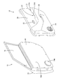
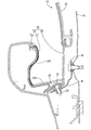
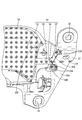
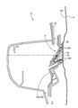
- FIG. 1 Perspective view of a vehicle door with a vehicle door trim Perspective view showing vehicle door trim and body panel A cross-sectional view of a portion of the vehicle door shown in FIG. 1 including a pull handle member.
- Perspective view of pull handle member Enlarged view of the front overhang of the pull handle member
- the door trim 10 (interior material for vehicles) related to the technique described in the specification of the present application will be described with reference to FIGS. 1 to 10.
- the door trim 10 is a component of the vehicle door 11, and is attached to the vehicle interior side (vehicle interior side) surface (vehicle interior side surface) of the vehicle body panel 12 (vehicle body panel). ..
- the body panel 12 includes a door outer panel 13 and a door inner panel 14, which are in the shape of a panel, respectively.
- the door outer panel 13 and the door inner panel 14 (door panel for vehicles) are formed by pressing a metal panel such as iron or aluminum, and the outer surface of the door outer panel 13 and the vehicle of the door inner panel 14 are formed.
- the interior side surface 14A is painted. Between the door inner panel 14 and the door outer panel 13, various parts such as an elevating mechanism for raising and lowering the window glass 15 and a lock mechanism for locking the vehicle door 11 are arranged.
- the door trim 10 includes a trim board 20 (interior material main body), an armrest 21, an inside handle 22, a pull handle 23, a speaker grill 24, and a door pocket 25.
- the trim board 20 has a plate shape as a whole.
- the armrest 21 is formed so as to bulge from the trim board 20 toward the vehicle interior side.
- the speaker grill 24 covers the speaker 24A.
- the door trim 10 is configured by assembling a plurality of board members including the trim board 20.
- the trim board 20 is made of an electrically insulating synthetic resin material (for example, polypropylene) and serves as a base on which other board members are attached.
- the armrest 21 has an armrest surface 21A on which the occupant can place his arm.
- An armrest opening 21B that opens upward is formed in the front portion of the armrest surface 21A.
- the pull handle box 30 is assembled in the armrest opening 21B to form the pull handle 23.
- the pull handle box 30 includes a pull handle member 31 (assembly member) and a cover member 32.
- the pull handle member 31 has a substantially L-shaped cross section and opens upward and outward.
- the cover member 32 has a box shape, is arranged so as to close the opening on the outside of the pull handle member 31, and opens upward.
- the pull handle member 31 has a main body portion 33 and a mounting piece 34 (mounting portion).
- the main body 33 has a box shape and functions as a grip for the pull handle 23.
- the mounting piece 34 is formed so as to extend outward from the outer edge of the vehicle interior outside of the main body 33.
- the main body 33 has a lower wall 33A, a side wall 33B, a front wall 33C, and a rear wall 33D.
- the inner surfaces of the side wall portion 33B, the front wall portion 33C, and the rear wall portion 33D are surfaces that the occupant touches when using the pull handle 23.
- the lower wall portion 33A has a first fixing portion 36.
- the first fixing portion 36 is provided with an insertion hole 39, and as shown in FIG. 3, the first fastener 38 is inserted, and the first fixing portion 36 is fixed to the bracket 41 together with the cover member 32.
- the bracket 41 has an L shape and is fixed to the door inner panel 14 by a second fastener 40 described later.
- the mounting piece 34 has four insertion holes 35.
- the mounting piece 34 further has a second fixing portion 37 for fixing to the door inner panel 14.
- the second fixing portion 37 is formed in a portion (front overhanging portion) 34A of the mounting piece 34 that overhangs toward the front side of the vehicle.
- the second fixing portion 37 has an inclined shape in which the upper side is inclined toward the outside of the passenger compartment, and has an insertion hole 37A through which the fastener is inserted.
- a fastener is inserted into the insertion hole 37A and the fastening hole 42 formed in the door inner panel 14, and the second fixing portion 37 is fixed to the door inner panel 14.
- the pull handle member 31 is a member obtained by laminating and molding a conductive layer 51 on a base material 50.
- the base material 50 is made of an electrically insulating synthetic resin material (non-conductive resin material, for example, polypropylene).
- the conductive layer 51 is made of a conductive elastomer. The conductive layer 51 is shown with hatching in FIGS. 4 to 6.
- the base material 50 is formed in the shape of the pull handle member 31 described above.
- the base material 50 further has a first protrusion 50A and a second protrusion 50B.
- the first protrusion 50A and the second protrusion 50B are provided at positions adjacent to the second fixing portion 37 of the portion constituting the front overhanging portion 34A of the mounting piece 34.
- the conductive layer 51 has a contact surface portion 52, a first contact protrusion 53, a second contact protrusion 54, and a connecting portion 55.
- the contact surface portion 52 covers the entire portion of the base material 50 that constitutes the inner surface of the side wall portion 33B, the front wall portion 33C, and the rear wall portion 33D described above.
- the first contact protrusion 53 is formed so as to face the door inner panel 14 from the protruding end of the first protrusion 50A of the base material 50.
- the second contact protrusion 54 is formed so as to face the door inner panel 14 from the protruding end of the second protrusion 50B of the base material 50.
- the connecting portion 55 connects the contact surface portion 52, the first contact protrusion 53, and the second contact protrusion 54.
- the connecting portion 55 includes a portion formed on the surface of the portion between the edge of the contact surface portion 52 of the base material 50 and the base end of the first protrusion 50A and the second protrusion 50B, and the first protrusion 50A. Formed on the surface of the portion from the base end of the first contact protrusion 53 to the base end of the first contact protrusion 53, and formed on the surface of the portion from the base end of the second protrusion 50B to the base end of the second contact protrusion 54. Has a portion that has been made.
- the conductive layer 51 is made of, for example, a metal or carbon fine particles that are mixed with a thermoplastic elastomer to impart conductivity. Further, the electrical resistivity of the conductive layer 51 is larger than that of the metal door inner panel 14 and smaller than that of the trim board 20 and the base material 50.
- the electric resistance ground of the conductive layer 51 is interposed between the conductive path (body ground) connected to the vehicle body panel 12 and the occupant (human body), and causes pain or impact to the occupant when the occupant is charged with static electricity. It is set to a value that can eliminate static electricity without giving.
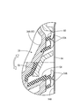
- the first contact protrusion 53 and the second contact protrusion 54 have their respective protruding ends located diagonally above their respective base ends and project toward the door inner panel 14. As shown in FIG. 5, the first contact protrusion 53 and the second contact protrusion 54 project further to the outside of the vehicle interior from the end of the second fixing portion 37 outside the vehicle interior (outside the vehicle interior). As shown in FIGS. 4 to 7, the base end of the first contact protrusion 53 has a cylindrical shape, and the protruding end has four contact pieces 53A. The contact pieces 53A are arranged at equal intervals in the circumferential direction so as to be formed by making a cross cut in a cylinder.
- the base end of the second contact protrusion 54 has a cylindrical shape, and the protruding end has four contact pieces 54A.
- the contact pieces 54A are arranged at equal intervals in the circumferential direction so as to be formed by making a cross cut in a cylinder.
- the contact pieces 53A and the first contact protrusion 53 of the first contact protrusion 53 are as shown in FIGS. 8 to 10. 2
- the contact piece 54A of the contact protrusion 54 comes into contact with the vehicle interior side surface 14A (vehicle interior side surface) of the door inner panel 14.
- the occupant can release the static electricity charged to the occupant from the conductive layer 51 of the pull handle member 31 to the door inner panel 14 simply by touching the inner surfaces of the side wall portion 33B, the front wall portion 33C, and the rear wall portion 33D. It is possible. That is, it is possible to release static electricity by the operation normally performed when the occupant grips the pull handle 23 when getting off the vehicle.
- a conduction path is formed so that static electricity flows to the vehicle body panel via an unpainted portion such as an inner peripheral surface of a mounting hole formed in the vehicle body panel.
- electricity having a large voltage such as static electricity is conducted. Therefore, according to the configuration of the door trim 10, static electricity can be released to the door inner panel 14 only by the occupant grasping the pull handle 23 when getting off.
- the door trim 10 has a simple structure that does not increase the number of parts and the manufacturing man-hours, and can eliminate static electricity charged on the occupant.
- the conductive layer 51 is made of an elastomer
- the first contact protrusion 53 and the second contact protrusion 54 can be elastically deformed.
- the contact pieces 53A and 54A come into contact with the vehicle interior side surface 14A of the door inner panel 14 in a state of being elastically deformed. That is, according to the door trim 10, when the occupant grips the pull handle 23, at least one of the contact pieces 53A and 54A comes into contact with the door inner panel 14 even if a part of the door trim 10 is twisted or deformed. Therefore, it is possible to surely release the static electricity charged on the occupant to the door inner panel 14.
- the contact pieces 53A and 54A are in contact with the vehicle interior side surface 14A of the door inner panel 14 in a state of being elastically deformed, but the contact pieces 53A and 54A are independently and relatively freely deformable. , All of the contact pieces 53A and 54A are unlikely to be separated from the door inner panel 14. With such a configuration, it is possible to more reliably avoid a situation in which the conduction between the conductive layer 51 and the vehicle body panel 12 is lost.
- the first contact protrusion 53 and the second contact protrusion 54 are provided adjacent to the second fixing portion 37. Since the second fixing portion 37 is fixed to the door inner panel 14, even if a part of the door trim 10 is twisted or deformed when the occupant grips the pull handle 23, the second fixing portion 37 is adjacent to the second fixing portion 37. The first contact protrusion 53 and the second contact protrusion 54 are difficult to separate from the door inner panel 14. Therefore, at least one of the contact pieces 53A and 54A can be kept in contact with the door inner panel 14.
- the second fixing portion 37 is composed of a part of the base material 50.
- the second fixing portion 37 is formed of a conductive elastomer, the pull handle member 31 and the vehicle body panel 12 can be easily made conductive, but the mounting strength to the door inner panel 14 is insufficient.
- the entire pull handle member 31 is molded with a conductive resin, the pull handle member 31 and the vehicle body panel 12 can be easily conductive and sufficient mounting strength can be obtained, but the cost increases and the tactile sensation on the contact surface is poor. It becomes a problem.
- the minimum necessary part of the door trim 10 is molded with a conductive elastomer. It is possible to suppress the cost increase due to the use of the conductive resin material and to make the contact surface have a good tactile sensation. Further, sufficient mounting strength to the door inner panel 14 can be obtained. According to the door trim 10, not only the static electricity charged on the occupant can be surely released to the vehicle body panel 12, but also the above-mentioned effect can be obtained.
- the pull handle member 31 is a single member formed by laminating a conductive layer 51 made of a conductive elastomer on a base material 50 made of a non-conductive resin.
- a single pull handle member 31 is attached to the trim board 20, and the door trim 10 is attached to the vehicle body panel 12, and an electrostatic conduction path is secured. In other words, there is no need for a work process for static elimination measures.
- the first contact protrusion 53 is located above the second fixed portion 37 and the second contact protrusion 54. That is, the first contact protrusion 53 and the second contact protrusion 54 are provided at positions opposite to each other with respect to the second fixing portion 37.
- a part of the door trim 10 turns in the vertical direction (in the direction of the white arrow shown in FIG. 10) with the second fixing portion 37 as a fulcrum. It may move. Even when such rotation occurs, either one of the first contact protrusion 53 and the second contact protrusion 54 is pressed against the door inner panel 14, so that the static electricity conduction path is reliable. To be secured.
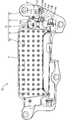
- the pull handle member 31 may be replaced with the pull handle member 70 shown in FIG.
- the pull handle member 70 is a single member formed by laminating a conductive layer 72 made of a conductive elastomer on a base material 71 made of a non-conductive resin.
- the pull handle member 70 the description of the same configuration as that of the pull handle member 31 will be omitted.
- the base material 71 has a first protrusion 71A, a second protrusion 71B, and a third protrusion 71C.
- the first protrusion 71A and the second protrusion 71B have the same configuration as the first protrusion 50A and the second protrusion 50B of the base material 50, respectively.
- the third protrusion 71C is provided at a position in front of the vehicle with respect to the insertion hole 37A of the second fixing portion 37.
- the third protrusion 71C has the same configuration as the second protrusion 71B, that is, the second protrusion 50B of the base material 50.
- the conductive layer 72 has a contact surface portion 52, a first contact protrusion 73, a second contact protrusion 74, a third contact protrusion 75, and a connecting portion 76.
- the first contact protrusion 73, the second contact protrusion 74, and the third contact protrusion 75 are provided at the protruding ends of the first protrusion 71A, the second protrusion 71B, and the third protrusion 71C of the base material 71, respectively. It is connected to the contact surface portion 52 by the connecting portion 76.
- the first contact protrusion 73 and the second contact protrusion 74 are provided at positions closer to the contact surface portion 52 (rear in the vehicle front-rear direction) than the third contact protrusion 75 and the second fixing portion 37. Further, in the vertical direction of the vehicle, the first contact protrusion 73 is located above the second fixed portion 37, and the second contact protrusion 74 is located below the second fixed portion 37.
- the third contact protrusion 75 is provided at a position in front of the vehicle with respect to the insertion hole 37A of the second fixing portion 37.
- the first contact protrusion 73 is formed so as to face the door inner panel 14 from the protruding end of the first protrusion 71A of the base material 71.
- the second contact protrusion 74 is formed so as to face the door inner panel 14 from the protruding end of the second protrusion 71B of the base material 71.
- the third contact protrusion 75 is formed so as to face the door inner panel 14 from the protruding end of the third protrusion 71C of the base material 71.
- the connecting portion 76 connects the contact surface portion 52, the first contact protrusion 73, the second contact protrusion 74, and the third contact protrusion 75.
- the bases of the first contact protrusion 73, the second contact protrusion 74, and the third contact protrusion 75 from the edge of the contact surface portion 52 near the first contact protrusion 73 and the second contact protrusion 74. It extends to the edge.
- the connecting portion 75 is a portion formed on the surface of a portion between the edge of the contact surface portion 73 of the base material 71 and the base ends of the first protrusion 71A, the second protrusion 71B, and the third protrusion 71C.
- the base end of the first contact protrusion 73 has a cylindrical shape, and the protruding end has four contact pieces 73A.
- the contact pieces 73A are arranged at equal intervals in the circumferential direction so as to be formed by making a cross cut in a cylinder.
- the base end of the second contact protrusion 74 has a cylindrical shape, and the protruding end has four contact pieces 74A.
- the contact pieces 74A are arranged at equal intervals in the circumferential direction so as to be formed by making a cross cut in a cylinder.
- the base end of the third contact protrusion 75 has a cylindrical shape, and the protruding end has four contact pieces 75A.
- the contact pieces 75A are arranged at equal intervals in the circumferential direction so as to be formed by making a cross cut in a cylinder.
- the occupant grips the pull handle member 70 and opens / closes the vehicle door 11 a part of the door trim 10 may rotate in the vertical direction with the second fixing portion 37 as a fulcrum. Even when such rotation occurs, at least one of the first contact protrusion 73, the second contact protrusion 74, and the third contact protrusion 75 will be pressed against the door inner panel 14. Therefore, even if a part of the door trim 10 is twisted or deformed when the pull handle member 70 is gripped to open and close the vehicle door 11, the static electricity conduction path is surely secured and the static electricity charged on the occupant is removed. It can be reliably released to the vehicle body panel 12. Further, the third contact protrusion 75 ensures a more reliable conduction path of static electricity as compared with the pull handle member 31, and the static electricity charged on the occupant can be surely released by the vehicle body panel 12.
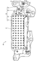
- the pull handle member 31 may be replaced with the pull handle member 80 shown in FIG.
- the pull handle member 80 is a single member formed by laminating a conductive layer 82 made of a conductive elastomer on a base material 81 made of a non-conductive resin.
- the pull handle members 80 the same configurations as the pull handle members 31 and 70 will be omitted.
- the base material 81 has a second fixing portion 87 having the same structure as the base material 50 but different from the second fixing portion 37.
- the second fixing portion 87 has an insertion hole 87A, and its use is the same as that of the insertion hole 37A provided in the base material 50.
- the second fixing portion 87 of the base material 81 has a larger dimension in the vehicle front-rear direction than the second fixing portion 37 of the base material 50, and the lower portion of the second fixing portion 37 also has a larger dimension in the vehicle front-rear direction. It has become.
- the base material 81 has a first protrusion 81A and a second protrusion 81B.
- the first protrusion 81A has the same configuration as the first protrusion 50A of the base material 50.
- the second protrusion 81B has the same configuration as the second protrusion 50B, but the position in the vehicle front-rear direction is different from that of the second protrusion 50B.
- the second protrusion 81B is provided in front of the vehicle with respect to the insertion hole 87A. Further, the pull handle member 70 is provided in front of the vehicle as compared with the third contact protrusion 75.
- the conductive layer 82 has a contact surface portion 52, a first contact protrusion 83, a second contact protrusion 84, and a connecting portion 85.
- the first contact protrusion 83 is provided at a position rearward and above the vehicle with respect to the second fixed portion 87.
- the second contact protrusion 84 is provided at a position in front of and below the vehicle through the insertion hole 87A of the second fixing portion 87.
- the insertion hole 87A is located between the first contact protrusion 83 and the second contact protrusion 84 in the front-rear direction of the vehicle.
- the first contact protrusion 83 is formed so as to face the door inner panel 14 from the protruding end of the first protrusion 81A of the base material 81.
- the second contact protrusion 84 is formed so as to face the door inner panel 14 from the protruding end of the second protrusion 81B of the base material 81.
- the connecting portion 85 connects the contact surface portion 52, the first contact protrusion 83, and the second contact protrusion 84. Specifically, it extends from the edge of the contact surface portion 52 near the first contact protrusion 83 to the base ends of the first contact protrusion 83, the second contact protrusion 84, and the third contact protrusion 85.
- the connecting portion 85 includes a portion formed on the surface of the portion between the edge of the contact surface portion 52 of the base material 81 and the base ends of the first protrusion 81A and the second protrusion 81B, and the first protrusion 81A. Formed on the surface of the portion from the base end of the first contact protrusion 83 to the base end of the first contact protrusion 83, and formed on the surface of the portion from the base end of the second protrusion 81B to the base end of the second contact protrusion 84. Has a portion that has been made.
- the first contact protrusion 83 has the same configuration as the first contact protrusion 53. Specifically, the base end has a cylindrical shape, and the protruding end has four contact pieces 83A. The contact pieces 83A are arranged at equal intervals in the circumferential direction so as to be formed by making a cross cut in the cylinder.
- the second contact protrusion 84 has the same configuration as the second contact protrusion 54, but the position in the vehicle front-rear direction is different from that of the second contact protrusion 54.
- the base end of the second contact protrusion 84 has a cylindrical shape, and the protruding end has four contact pieces 84A. The contact pieces 84A are arranged at equal intervals in the circumferential direction so as to be formed by making a cross cut in a cylinder.
- a part of the door trim 10 may rotate in the vertical direction with the second fixing portion 8737 as a fulcrum. Even when such rotation occurs, at least one of the contact pieces 83A and 84A is pressed against the door inner panel 14. Therefore, even if a part of the door trim is twisted or deformed when the pull handle member 80 is gripped to open and close the vehicle door 11, the static electricity conduction path is surely secured, and the static electricity charged on the occupant is removed from the vehicle body. It can be surely released to the panel 12.
- the pull handle member 80 can be more stably fixed to the door inner panel 14. Since the dimensions of the second fixing portion 87 and the lower portion thereof in the vehicle front-rear direction are larger than those of the second fixing portion 37 and the lower portion thereof of the base material 71, the rotation in the vertical direction with the second fixing portion 87 as a fulcrum is large. There is a possibility of becoming. However, since the second contact protrusion 84 is provided in front of the vehicle as compared with the third contact protrusion 75 of the pull handle member 70, at least one of the contact pieces 83A and 84A is provided even when the rotation is large.
- the pull handle member 31 may be replaced with the pull handle member 100 shown in FIG.
- the pull handle member 100 includes a conductive layer 101 having a structure different from that of the conductive layer 51 of the pull handle member 31.
- the conductive layer 101 has a first contact protrusion 102 and a second contact protrusion 103 having different configurations from the first contact protrusion 53 and the second contact protrusion 54 of the conductive layer 51.
- Other configurations of the conductive layer 101 are the same as those of the conductive layer 51.
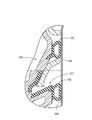
- the first contact protrusion 102 and the second contact protrusion 103 of the conductive layer 101 protrude from the base material 50 and have a protruding end having a shape bulging toward the outside of the vehicle interior.
- Each protruding end has a cylindrical shape extending in the front-rear direction of the vehicle. Then, when the door trim 10 is attached to the vehicle body panel 12, as shown in FIG. 13, the cylindrical tip is crushed in the vehicle interior / exterior direction (vehicle interior / exterior direction), and the interior of the door inner panel 14 is collapsed. It comes into contact with the side surface 14A.
- the door trim 10 has the vehicle interior side surface 14A of the door inner panel 14 in a state where the protruding ends of the first contact protrusion 102 and the second contact protrusion 103 are elastically deformed in the vehicle interior / exterior direction (vehicle interior / exterior direction). Is in contact with.
- the first contact protrusion 102 and the second contact protrusion 103 are independently and relatively freely deformable, and at least one of the first contact protrusion 102 and the second contact protrusion 103 is a door inner panel.
- the state of being in contact with 14 can be maintained. It is possible to more reliably avoid the situation where the conduction between the conductive layer 101 and the vehicle body panel 12 is lost, and to reliably release the static electricity charged on the occupant to the vehicle body panel 12.
- the technique described in the specification of the present application can also be adopted for a door grip arranged on a door trim in a form extending in the vertical direction. Further, the technique described in the present specification can also be adopted for vehicle interior materials such as a quarter trim provided with a grip portion for the occupant to maintain a posture and a ceiling interior material provided with an assist grip. be. Further, the techniques described in the present specification may be applied to vehicles such as trains and amusement vehicles as ground vehicles, airplanes and helicopters as flight vehicles, and ships and submersibles as marine and underwater vehicles. can.
Landscapes
- Engineering & Computer Science (AREA)
- Mechanical Engineering (AREA)
- Vehicle Interior And Exterior Ornaments, Soundproofing, And Insulation (AREA)
- Elimination Of Static Electricity (AREA)
Abstract
Description
Claims (11)
- 乗物本体を構成する金属製の乗物本体パネルの面のうち、乗物室内側に配置される乗物室内側面に取り付けられる乗物用内装材であって、
全体として板状をなす内装材本体と、
前記内装材本体に組み付けられて乗員の手が触れる接触面を有する組付部材と、を備え、
前記組付部材は、乗員が把持する本体部と、前記本体部から延出し、前記乗物本体パネルに取り付けるための取付部と、を有する基材と、導電性エラストマーからなり、前記基材に積層された導電層と、を有し、
前記導電層は、前記接触面を形成する接触面部と、前記基材から前記乗物本体パネルに向かうように突出する少なくとも1つの接触突部と、前記接触面部と前記接触突部とを連結する連結部と、を有し、
当該乗物用内装材が前記乗物本体パネルに取り付けられた場合に、前記接触突部の突出端が弾性変形した状態で前記乗物本体パネルの前記乗物室内側面に接することを特徴とする乗物用内装材。 - 前記接触突部の前記突出端は、複数の接触片を有し、前記複数の接触片は独立して弾性変形した状態で前記乗物本体パネルに接するように構成された請求項1に記載の乗物用内装材。
- 前記接触突部の前記突出端は、乗物室内外方向に変形可能に構成され、潰れた状態で前記乗物本体パネルに接するように構成された請求項1に記載の乗物用内装材。
- 前記取付部は、前記乗物本体パネルに固定するための固定部を備え、
前記接触突部は、前記固定部に隣接して設けられている請求項1から請求項3のいずれか1項に記載の乗物用内装材。 - 前記少なくとも1つの接触突部は2つの接触突部とされ、
前記接触突部は、前記固定部に対し互いに反対側となる位置に設けられている請求項4に記載の乗物用内装材。 - 前記内装材本体は、乗物用ドアパネルに取り付けられるトリムボードを備え、前記組付部材は、プルハンドル部材を備える請求項1から請求項5のいずれか1項に記載の乗物用内装材。
- 前記接触突部は、前記固定部の乗物室外側の端部より、さらに乗物室外側に突出している請求項4または請求項5に記載の乗物用内装材。
- 前記取付部は、前記乗物本体パネルに固定するための固定部と、前記固定部に隣接して設けられた突部を有し、
前記突部は、前記取付部の乗物室外側の面から乗物室外側に向かって突出し、
前記少なくとも1つの接触突部は、前記突部の突出端に設けられている請求項1から請求項3のいずれか1項に記載の乗物用内装材。 - 前記導電層の前記連結部は、前記接触面部に近い端縁と前記突部の基端との間の部分の表面に形成された部分と、前記突部の基端から前記接触突部の基端までの部分の表面に形成された部分と、を有する請求項8に記載の乗物用内装材。
- 前記取付部は、前記乗物本体パネルに固定するための固定部と、前記固定部に隣接して設けられた第1突部および第2突部を有し、
前記第1突部および前記第2突部は、前記取付部の乗物室外側の面から乗物室外側に向かって突出し、
前記第1突部および前記第2突部は、前記固定部に対して互いに反対側となる位置に設けられ、
前記少なくとも1つの接触突部は、第1接触突部と、第2接触突部と、を有し、
前記第1接触突部は、前記第1突部の突出端に設けられ、
前記第2接触突部は、前記第2突部の突出端に設けられている請求項1から請求項3のいずれか1項に記載の乗物用内装材。 - 前記導電層の連結部は、前記接触面部に近い端縁と前記第1突部の基端および前記第2突部の基端との間の部分の表面に形成された部分と、前記第1突部の基端から前記第1接触突部の基端までの部分の表面に形成された部分と、前記第2突部の基端から前記第2接触突部の基端までの部分の表面に形成された部分と、を有する請求項10に記載の乗物用内装材。
Priority Applications (2)
| Application Number | Priority Date | Filing Date | Title |
|---|---|---|---|
| US17/908,022 US12252076B2 (en) | 2020-03-11 | 2021-03-03 | Vehicular interior component |
| CN202180020313.1A CN115335248B (zh) | 2020-03-11 | 2021-03-03 | 乘用工具用内饰件 |
Applications Claiming Priority (2)
| Application Number | Priority Date | Filing Date | Title |
|---|---|---|---|
| JP2020-041559 | 2020-03-11 | ||
| JP2020041559A JP7432401B2 (ja) | 2020-03-11 | 2020-03-11 | 乗物用内装材 |
Publications (1)
| Publication Number | Publication Date |
|---|---|
| WO2021182234A1 true WO2021182234A1 (ja) | 2021-09-16 |
Family
ID=77670703
Family Applications (1)
| Application Number | Title | Priority Date | Filing Date |
|---|---|---|---|
| PCT/JP2021/008172 Ceased WO2021182234A1 (ja) | 2020-03-11 | 2021-03-03 | 乗物用内装材 |
Country Status (4)
| Country | Link |
|---|---|
| US (1) | US12252076B2 (ja) |
| JP (1) | JP7432401B2 (ja) |
| CN (1) | CN115335248B (ja) |
| WO (1) | WO2021182234A1 (ja) |
Families Citing this family (1)
| Publication number | Priority date | Publication date | Assignee | Title |
|---|---|---|---|---|
| JP7622556B2 (ja) * | 2021-06-03 | 2025-01-28 | トヨタ紡織株式会社 | 乗物用内装材 |
Citations (4)
| Publication number | Priority date | Publication date | Assignee | Title |
|---|---|---|---|---|
| JPH0572588U (ja) * | 1992-03-06 | 1993-10-05 | 西川化成株式会社 | 内装パネルのポケット取付構造 |
| JPH0958378A (ja) * | 1995-08-25 | 1997-03-04 | Kazuo Aoki | 自動車のドアに取りつける、人体の帯電気を車体に流出する装置 |
| US5825605A (en) * | 1996-09-27 | 1998-10-20 | Sutherland; Colin A. | Electrostatic shock prevention device for use in vehicles |
| JP2019084838A (ja) * | 2017-11-01 | 2019-06-06 | トヨタ紡織株式会社 | 車両用内装材 |
Family Cites Families (4)
| Publication number | Priority date | Publication date | Assignee | Title |
|---|---|---|---|---|
| DE19954648B4 (de) * | 1999-11-13 | 2007-10-25 | Brose Fahrzeugteile Gmbh & Co. Kommanditgesellschaft, Coburg | Fahrzeugtür mit einer in einem Naßraum und einen Trockenraum getrennten Türkarosserie |
| JP4161664B2 (ja) * | 2002-09-27 | 2008-10-08 | アイシン精機株式会社 | 車両用ドアハンドル装置 |
| JP5999441B2 (ja) * | 2013-04-11 | 2016-09-28 | トヨタ紡織株式会社 | ドアトリム |
| CN207974667U (zh) * | 2017-12-28 | 2018-10-16 | 天津沃尔德泰克机电有限公司 | 一种新型的汽车车门把手 |
-
2020
- 2020-03-11 JP JP2020041559A patent/JP7432401B2/ja active Active
-
2021
- 2021-03-03 US US17/908,022 patent/US12252076B2/en active Active
- 2021-03-03 WO PCT/JP2021/008172 patent/WO2021182234A1/ja not_active Ceased
- 2021-03-03 CN CN202180020313.1A patent/CN115335248B/zh active Active
Patent Citations (4)
| Publication number | Priority date | Publication date | Assignee | Title |
|---|---|---|---|---|
| JPH0572588U (ja) * | 1992-03-06 | 1993-10-05 | 西川化成株式会社 | 内装パネルのポケット取付構造 |
| JPH0958378A (ja) * | 1995-08-25 | 1997-03-04 | Kazuo Aoki | 自動車のドアに取りつける、人体の帯電気を車体に流出する装置 |
| US5825605A (en) * | 1996-09-27 | 1998-10-20 | Sutherland; Colin A. | Electrostatic shock prevention device for use in vehicles |
| JP2019084838A (ja) * | 2017-11-01 | 2019-06-06 | トヨタ紡織株式会社 | 車両用内装材 |
Also Published As
| Publication number | Publication date |
|---|---|
| US12252076B2 (en) | 2025-03-18 |
| CN115335248B (zh) | 2025-07-22 |
| US20230091162A1 (en) | 2023-03-23 |
| JP2021142814A (ja) | 2021-09-24 |
| CN115335248A (zh) | 2022-11-11 |
| JP7432401B2 (ja) | 2024-02-16 |
Similar Documents
| Publication | Publication Date | Title |
|---|---|---|
| JP6944343B2 (ja) | 車両用内装材 | |
| US4848829A (en) | Door trim panel assembly | |
| WO2021182234A1 (ja) | 乗物用内装材 | |
| JP7604532B2 (ja) | 車両内装部材 | |
| CN103895509B (zh) | 用于车辆的离合器踏板的组合开关装置 | |
| JP7622556B2 (ja) | 乗物用内装材 | |
| US11987105B2 (en) | Vehicular interior component | |
| JP5168531B2 (ja) | ドアトリム | |
| JP2019182087A (ja) | 機能部品の取付構造 | |
| JP7261375B2 (ja) | 車両の内装構造 | |
| JP2018090144A (ja) | 乗物用シート | |
| JP3153240B2 (ja) | 自動車用の操縦ハンドル | |
| JP5033514B2 (ja) | 自動車用内装部品 | |
| US12600279B2 (en) | Vehicular door trim | |
| CN221125773U (zh) | 开关总成、车门总成、车辆 | |
| JP7754012B2 (ja) | 乗物用ドアトリム | |
| JPH10172787A (ja) | 車両用静電ショック防止装置 | |
| JP2023167458A (ja) | 車両用内装材の取付構造 | |
| JP5796358B2 (ja) | カウルサイドトリム、及びカウルサイドトリムの組付構造 | |
| WO2025197074A1 (ja) | コンセント取り付け構造 | |
| JPH02120479A (ja) | 車両のドアハンドル構造 | |
| CN114771445A (zh) | 一种驾乘人员静电消除装置及车辆 | |
| CN113790000A (zh) | 一种电子反馈车门把手 | |
| JPH0572588U (ja) | 内装パネルのポケット取付構造 | |
| WO2025197073A1 (ja) | コンセント取り付け構造 |
Legal Events
| Date | Code | Title | Description |
|---|---|---|---|
| 121 | Ep: the epo has been informed by wipo that ep was designated in this application |
Ref document number: 21767499 Country of ref document: EP Kind code of ref document: A1 |
|
| NENP | Non-entry into the national phase |
Ref country code: DE |
|
| 122 | Ep: pct application non-entry in european phase |
Ref document number: 21767499 Country of ref document: EP Kind code of ref document: A1 |
|
| WWG | Wipo information: grant in national office |
Ref document number: 17908022 Country of ref document: US |
|
| WWG | Wipo information: grant in national office |
Ref document number: 202180020313.1 Country of ref document: CN |