WO2021182032A1 - 欠陥検出方法、欠陥検出装置及び造形装置 - Google Patents
欠陥検出方法、欠陥検出装置及び造形装置 Download PDFInfo
- Publication number
- WO2021182032A1 WO2021182032A1 PCT/JP2021/005711 JP2021005711W WO2021182032A1 WO 2021182032 A1 WO2021182032 A1 WO 2021182032A1 JP 2021005711 W JP2021005711 W JP 2021005711W WO 2021182032 A1 WO2021182032 A1 WO 2021182032A1
- Authority
- WO
- WIPO (PCT)
- Prior art keywords
- defect
- detection method
- absence
- internal defect
- internal
- Prior art date
- Legal status (The legal status is an assumption and is not a legal conclusion. Google has not performed a legal analysis and makes no representation as to the accuracy of the status listed.)
- Ceased
Links
Images




Classifications
-
- B—PERFORMING OPERATIONS; TRANSPORTING
- B22—CASTING; POWDER METALLURGY
- B22F—WORKING METALLIC POWDER; MANUFACTURE OF ARTICLES FROM METALLIC POWDER; MAKING METALLIC POWDER; APPARATUS OR DEVICES SPECIALLY ADAPTED FOR METALLIC POWDER
- B22F10/00—Additive manufacturing of workpieces or articles from metallic powder
- B22F10/20—Direct sintering or melting
- B22F10/25—Direct deposition of metal particles, e.g. direct metal deposition [DMD] or laser engineered net shaping [LENS]
-
- B—PERFORMING OPERATIONS; TRANSPORTING
- B22—CASTING; POWDER METALLURGY
- B22F—WORKING METALLIC POWDER; MANUFACTURE OF ARTICLES FROM METALLIC POWDER; MAKING METALLIC POWDER; APPARATUS OR DEVICES SPECIALLY ADAPTED FOR METALLIC POWDER
- B22F10/00—Additive manufacturing of workpieces or articles from metallic powder
- B22F10/50—Treatment of workpieces or articles during build-up, e.g. treatments applied to fused layers during build-up
-
- B—PERFORMING OPERATIONS; TRANSPORTING
- B22—CASTING; POWDER METALLURGY
- B22F—WORKING METALLIC POWDER; MANUFACTURE OF ARTICLES FROM METALLIC POWDER; MAKING METALLIC POWDER; APPARATUS OR DEVICES SPECIALLY ADAPTED FOR METALLIC POWDER
- B22F10/00—Additive manufacturing of workpieces or articles from metallic powder
- B22F10/80—Data acquisition or data processing
- B22F10/85—Data acquisition or data processing for controlling or regulating additive manufacturing processes
-
- B—PERFORMING OPERATIONS; TRANSPORTING
- B22—CASTING; POWDER METALLURGY
- B22F—WORKING METALLIC POWDER; MANUFACTURE OF ARTICLES FROM METALLIC POWDER; MAKING METALLIC POWDER; APPARATUS OR DEVICES SPECIALLY ADAPTED FOR METALLIC POWDER
- B22F12/00—Apparatus or devices specially adapted for additive manufacturing; Auxiliary means for additive manufacturing; Combinations of additive manufacturing apparatus or devices with other processing apparatus or devices
- B22F12/40—Radiation means
- B22F12/41—Radiation means characterised by the type, e.g. laser or electron beam
- B22F12/43—Radiation means characterised by the type, e.g. laser or electron beam pulsed; frequency modulated
-
- B—PERFORMING OPERATIONS; TRANSPORTING
- B22—CASTING; POWDER METALLURGY
- B22F—WORKING METALLIC POWDER; MANUFACTURE OF ARTICLES FROM METALLIC POWDER; MAKING METALLIC POWDER; APPARATUS OR DEVICES SPECIALLY ADAPTED FOR METALLIC POWDER
- B22F12/00—Apparatus or devices specially adapted for additive manufacturing; Auxiliary means for additive manufacturing; Combinations of additive manufacturing apparatus or devices with other processing apparatus or devices
- B22F12/90—Means for process control, e.g. cameras or sensors
-
- B—PERFORMING OPERATIONS; TRANSPORTING
- B29—WORKING OF PLASTICS; WORKING OF SUBSTANCES IN A PLASTIC STATE IN GENERAL
- B29C—SHAPING OR JOINING OF PLASTICS; SHAPING OF MATERIAL IN A PLASTIC STATE, NOT OTHERWISE PROVIDED FOR; AFTER-TREATMENT OF THE SHAPED PRODUCTS, e.g. REPAIRING
- B29C64/00—Additive manufacturing, i.e. manufacturing of three-dimensional [3D] objects by additive deposition, additive agglomeration or additive layering, e.g. by 3D printing, stereolithography or selective laser sintering
- B29C64/20—Apparatus for additive manufacturing; Details thereof or accessories therefor
- B29C64/264—Arrangements for irradiation
- B29C64/268—Arrangements for irradiation using laser beams; using electron beams [EB]
-
- B—PERFORMING OPERATIONS; TRANSPORTING
- B29—WORKING OF PLASTICS; WORKING OF SUBSTANCES IN A PLASTIC STATE IN GENERAL
- B29C—SHAPING OR JOINING OF PLASTICS; SHAPING OF MATERIAL IN A PLASTIC STATE, NOT OTHERWISE PROVIDED FOR; AFTER-TREATMENT OF THE SHAPED PRODUCTS, e.g. REPAIRING
- B29C64/00—Additive manufacturing, i.e. manufacturing of three-dimensional [3D] objects by additive deposition, additive agglomeration or additive layering, e.g. by 3D printing, stereolithography or selective laser sintering
- B29C64/30—Auxiliary operations or equipment
- B29C64/386—Data acquisition or data processing for additive manufacturing
- B29C64/393—Data acquisition or data processing for additive manufacturing for controlling or regulating additive manufacturing processes
-
- B—PERFORMING OPERATIONS; TRANSPORTING
- B33—ADDITIVE MANUFACTURING TECHNOLOGY
- B33Y—ADDITIVE MANUFACTURING, i.e. MANUFACTURING OF THREE-DIMENSIONAL [3D] OBJECTS BY ADDITIVE DEPOSITION, ADDITIVE AGGLOMERATION OR ADDITIVE LAYERING, e.g. BY 3D PRINTING, STEREOLITHOGRAPHY OR SELECTIVE LASER SINTERING
- B33Y30/00—Apparatus for additive manufacturing; Details thereof or accessories therefor
-
- B—PERFORMING OPERATIONS; TRANSPORTING
- B33—ADDITIVE MANUFACTURING TECHNOLOGY
- B33Y—ADDITIVE MANUFACTURING, i.e. MANUFACTURING OF THREE-DIMENSIONAL [3D] OBJECTS BY ADDITIVE DEPOSITION, ADDITIVE AGGLOMERATION OR ADDITIVE LAYERING, e.g. BY 3D PRINTING, STEREOLITHOGRAPHY OR SELECTIVE LASER SINTERING
- B33Y40/00—Auxiliary operations or equipment, e.g. for material handling
-
- B—PERFORMING OPERATIONS; TRANSPORTING
- B33—ADDITIVE MANUFACTURING TECHNOLOGY
- B33Y—ADDITIVE MANUFACTURING, i.e. MANUFACTURING OF THREE-DIMENSIONAL [3D] OBJECTS BY ADDITIVE DEPOSITION, ADDITIVE AGGLOMERATION OR ADDITIVE LAYERING, e.g. BY 3D PRINTING, STEREOLITHOGRAPHY OR SELECTIVE LASER SINTERING
- B33Y50/00—Data acquisition or data processing for additive manufacturing
- B33Y50/02—Data acquisition or data processing for additive manufacturing for controlling or regulating additive manufacturing processes
-
- G—PHYSICS
- G01—MEASURING; TESTING
- G01N—INVESTIGATING OR ANALYSING MATERIALS BY DETERMINING THEIR CHEMICAL OR PHYSICAL PROPERTIES
- G01N29/00—Investigating or analysing materials by the use of ultrasonic, sonic or infrasonic waves; Visualisation of the interior of objects by transmitting ultrasonic or sonic waves through the object
- G01N29/04—Analysing solids
- G01N29/043—Analysing solids in the interior, e.g. by shear waves
-
- G—PHYSICS
- G01—MEASURING; TESTING
- G01N—INVESTIGATING OR ANALYSING MATERIALS BY DETERMINING THEIR CHEMICAL OR PHYSICAL PROPERTIES
- G01N29/00—Investigating or analysing materials by the use of ultrasonic, sonic or infrasonic waves; Visualisation of the interior of objects by transmitting ultrasonic or sonic waves through the object
- G01N29/04—Analysing solids
- G01N29/12—Analysing solids by measuring frequency or resonance of acoustic waves
-
- G—PHYSICS
- G01—MEASURING; TESTING
- G01N—INVESTIGATING OR ANALYSING MATERIALS BY DETERMINING THEIR CHEMICAL OR PHYSICAL PROPERTIES
- G01N29/00—Investigating or analysing materials by the use of ultrasonic, sonic or infrasonic waves; Visualisation of the interior of objects by transmitting ultrasonic or sonic waves through the object
- G01N29/22—Details, e.g. general constructional or apparatus details
- G01N29/24—Probes
- G01N29/2418—Probes using optoacoustic interaction with the material, e.g. laser radiation, photoacoustics
-
- B—PERFORMING OPERATIONS; TRANSPORTING
- B22—CASTING; POWDER METALLURGY
- B22F—WORKING METALLIC POWDER; MANUFACTURE OF ARTICLES FROM METALLIC POWDER; MAKING METALLIC POWDER; APPARATUS OR DEVICES SPECIALLY ADAPTED FOR METALLIC POWDER
- B22F2999/00—Aspects linked to processes or compositions used in powder metallurgy
-
- G—PHYSICS
- G01—MEASURING; TESTING
- G01N—INVESTIGATING OR ANALYSING MATERIALS BY DETERMINING THEIR CHEMICAL OR PHYSICAL PROPERTIES
- G01N2291/00—Indexing codes associated with group G01N29/00
- G01N2291/01—Indexing codes associated with the measuring variable
- G01N2291/014—Resonance or resonant frequency
-
- G—PHYSICS
- G01—MEASURING; TESTING
- G01N—INVESTIGATING OR ANALYSING MATERIALS BY DETERMINING THEIR CHEMICAL OR PHYSICAL PROPERTIES
- G01N2291/00—Indexing codes associated with group G01N29/00
- G01N2291/02—Indexing codes associated with the analysed material
- G01N2291/028—Material parameters
- G01N2291/0289—Internal structure, e.g. defects, grain size, texture
-
- Y—GENERAL TAGGING OF NEW TECHNOLOGICAL DEVELOPMENTS; GENERAL TAGGING OF CROSS-SECTIONAL TECHNOLOGIES SPANNING OVER SEVERAL SECTIONS OF THE IPC; TECHNICAL SUBJECTS COVERED BY FORMER USPC CROSS-REFERENCE ART COLLECTIONS [XRACs] AND DIGESTS
- Y02—TECHNOLOGIES OR APPLICATIONS FOR MITIGATION OR ADAPTATION AGAINST CLIMATE CHANGE
- Y02P—CLIMATE CHANGE MITIGATION TECHNOLOGIES IN THE PRODUCTION OR PROCESSING OF GOODS
- Y02P10/00—Technologies related to metal processing
- Y02P10/25—Process efficiency
Definitions
- This disclosure relates to a defect detection method, a defect detection device, and a modeling device.
- Patent Document 1 discloses an apparatus that monitors the temperature of a growing portion and adjusts the beam output to be irradiated based on the temperature in the laminated modeling.
- the 3D modeled product formed by the additional modeling technique is integrally molded using metal powder as a material, so that there is no intermediate product and it is necessary to inspect all parts in the final shape.
- Patent Document 1 does not disclose a method for solving such a problem of internal defects.
- laser ultrasonic method is known as a method for detecting internal defects without contact.
- the surface of an object to be inspected is irradiated with pulsed laser light to locally heat the surface of the object to be inspected, and ultrasonic waves are generated by thermal expansion or ablation, and the generated ultrasonic waves are the object to be inspected.
- a detection device such as a laser interferometer to measure what has propagated inside, reflected or scattered by internal defects, and propagated to the surface again.
- the defect detection method is A step of irradiating an object with a pulsed laser beam to continuously generate ultrasonic waves in the object, A step of detecting the presence or absence of the internal defect of the object based on the presence or absence of resonance of the ultrasonic wave generated between the surface of the object and the internal defect. including.
- the defect detection device is A pulse laser irradiation device for irradiating an object with pulsed laser light to continuously generate ultrasonic waves in the object.
- the vibration of the surface of the object based on the ultrasonic wave is detected, the presence or absence of resonance of the ultrasonic wave is detected, and the presence or absence of resonance of the ultrasonic wave generated between the surface of the object and an internal defect is used.
- a detection device configured to detect the presence or absence of the internal defect of the object, and To be equipped.
- the modeling apparatus is A beam irradiation device for 3D modeling of an object, With the above defect detection device, To be equipped.
- a defect detection method it is possible to provide a defect detection method, a defect detection device, and a modeling device suitable for detecting internal defects of an object to be 3D modeled.
- expressions such as “same”, “equal”, and “homogeneous” that indicate that things are in the same state not only represent exactly the same state, but also have tolerances or differences to the extent that the same function can be obtained. It shall also represent the existing state.
- an expression representing a shape such as a quadrangular shape or a cylindrical shape not only represents a shape such as a quadrangular shape or a cylindrical shape in a geometrically strict sense, but also an uneven portion or chamfering within a range in which the same effect can be obtained.
- the shape including the part and the like shall also be represented.
- the expressions “equipped”, “equipped”, “equipped”, “included”, or “have” one component are not exclusive expressions that exclude the existence of other components.
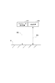
- FIG. 1 is a diagram schematically showing a configuration of a modeling apparatus 300 according to an embodiment.
- optical systems such as a collimating lens and a condenser lens are omitted.
- the modeling device 300 including the defect detecting device 200 will be described, but the defect detecting device 200 may be a device independent of the modeling device 300.
- the modeling device 300 includes a beam irradiation device 100 for 3D modeling the object T and a defect detection device 200 for detecting an internal defect.
- the modeling device 300 is, for example, a device that performs powder bed type additional modeling (AM).
- the modeling device 300 may be a device that performs modeling by the LMD (Laser Metal Deposition) method.
- the beam irradiating device 100 is configured to irradiate the raw material powder (for example, alloy powder) spread as a powder bed with the energy beam B1 according to a shape based on an arbitrary CAD. As a result, the beam irradiation device 100 melts and solidifies the raw material powder to form the object T in 3D.
- the beam irradiating device 100 is a device that irradiates a laser beam for processing as an energy beam B1.
- the modeling apparatus 300 may further include a galvano mirror 101. In this case, the galvanometer mirror 101 can change the direction of the energy beam B1 to scan on the powder bed.
- the beam irradiation device 100 is not limited to the above configuration.
- the beam irradiating device 100 may be a device that irradiates an electron beam as an energy beam B1.
- the modeling apparatus 300 may be configured not to include the galvano mirror 101.
- the modeling device 300 may have a configuration in which the beam irradiation device 100 itself is moved or rotated to scan the energy beam B1.
- the defect detection device 200 includes a pulse laser irradiation device 201 configured to irradiate the object T with the pulsed laser beam B2, a detection device 202 configured to detect the presence or absence of internal defects in the object T, and the like.
- a control device 203 configured to control these is provided.
- the pulse laser irradiation device 201 irradiates the object T with the pulse laser light B2 to continuously generate ultrasonic waves in the object T.
- the ultrasonic wave is, for example, a burst wave of 20 MHz or 30 MHz. This frequency is the same as the frequency (repetition frequency) in the repetition of the pulse of the pulsed laser beam B2.
- the "pulse laser” includes a laser that changes the output of a continuously oscillating laser at a specific cycle.
- the pulse laser irradiation device 201 preferably irradiates the pulse laser light B2 from directly above so that the intensity of the reflected wave is high. Further, in the case of the powder bed type additional modeling, it is preferable to irradiate the portion of the object T exposed from the powder with the pulsed laser beam B2.
- the detection device 202 is configured to detect the vibration of the surface of the object T based on the ultrasonic wave and detect the presence or absence of resonance of the ultrasonic wave. Further, the detection device 202 is configured to detect the presence or absence of an internal defect of the object T based on the presence or absence of resonance of ultrasonic waves generated between the surface of the object T and the internal defect. Internal defects are processing defects such as cracks and voids.
- the detection device 202 may include, for example, a laser interferometer.
- the detection device 202 is configured to irradiate the object T with the laser beam B3, receive the reflected light, and measure the displacement, that is, the vibration of the surface of the object T.
- the laser light B3 is preferably a laser light having a wavelength different from that of the pulse laser light B2.
- the pulsed laser light B2 has an infrared wavelength and the laser light B3 has a visible light wavelength, even if both lights overlap, it is easy to separate them at the time of detection.
- a Doppler vibrometer may be provided as a configuration including a laser interferometer.
- the defect detection device 200 may further include a galvano mirror 204.
- the galvanometer mirror 204 can change the direction of the pulsed laser beam B2 or the laser beam B3 to scan on the powder bed.
- the defect detection device 200 may include a half mirror 205.
- the pulse laser light B2 and the laser light B3 may be incident on the galvano mirror 204 via the half mirror 205, and the directions of the pulse laser light B2 and the laser light B3 may be changed. can. According to such a configuration, it is suitable for irradiating the laser beam B3 at the same position as the irradiation position of the pulsed laser beam B2.
- the defect detection device 200 may not be provided with the galvanometer mirror 204.
- the defect detection device 200 may have a configuration in which the pulse laser irradiation device 201 itself or the detection device 202 itself is moved or rotated to scan the pulse laser light B2 or the laser light B3.
- the defect detection device 200 may be configured not to include the half mirror 205.
- the defect detection device 200 may include a beam splitter instead of the half mirror 205.
- the defect detection device 200 may be configured not to include the half mirror 205 and the beam splitter, or may be configured to be able to scan the pulsed laser beam B2 and the laser beam B3 independently.
- the control device 203 is composed of a CPU (Central Processing Unit), a RAM (Random Access Memory), a ROM (Read Only Memory), and the like.
- the control device 203 controls the operation of the entire device by, for example, executing a program stored in the ROM or RAM. Further, the control device 203 stores various data (for example, design information of the object T, a detection signal, a reference signal, and information related to the setting of the repetition frequency) described later in the ROM or RAM.
- the control device 203 may be integrated with the pulse laser irradiation device 201 or the detection device 202. Further, the control device 203 may be configured to control the galvano mirror 204. The defect detection device 200 may be configured not to include the control device 203. For example, instead of the automatic control by the control device 203, the user may manually operate the control.
- defect detection method defect detection methods according to some embodiments will be described.
- the defect detection method described below may be automatically executed by the control process of the control device 203, or some procedures may be executed manually by the user instead of the control device 203.
- the defect detection method according to one embodiment is applied to, for example, powder bed type additional molding (AM).
- the defect detection method can also be applied to an object to be modeled by another method such as the LMD method.
- FIG. 2 is a conceptual diagram for explaining the principle of the defect detection method according to the embodiment.
- FIG. 3 is a conceptual diagram for explaining the principle of the defect detection method according to the embodiment.
- FIG. 4 is a conceptual diagram for explaining the principle of the defect detection method according to the embodiment.
- FIG. 5 is a flowchart showing the procedure of the defect detection method according to the embodiment.
- the depth at which internal defects are likely to occur can be estimated from the design information.
- the detection depth can be set to a detection depth at which an internal defect may occur, and the defect can be detected.
- the repetition frequency of the pulsed laser beam B2 is set (step S1). This setting may be performed by the user based on the knowledge, or may be performed by the control device 203 based on the design information.
- the repetition frequency of the pulsed laser beam B2 so that the depth from the surface of the object T to the internal defect to be detected corresponds to a frequency having a half wavelength.
- the repetition frequency is set so that the distance d to the position where the internal defect shown in FIG. 3 exists corresponds to the frequency at which the half wavelength is half wavelength.
- the frequency may be set to that frequency, or the frequency may be set to a frequency in which a measurement error is added to the frequency.
- the repetition frequency may be set based on a frequency that is an integral multiple of the half wavelength instead of the half wavelength.
- it is more suitable in terms of accuracy to measure the distance at a repetition frequency corresponding to a half wavelength as described above.
- a reference signal indicating the vibration of the surface of the object T obtained when the pulsed laser beam B2 is irradiated at a position where it is estimated that there is no internal defect directly underneath is acquired (step S2).
- the object T is irradiated with the pulsed laser beam B2 to continuously generate ultrasonic waves in the object T.
- the vibration of the surface of the object T based on ultrasonic waves is measured by the detection device 202.
- the reference signal can be acquired.
- the laser beam B3 is used for the measurement. It is preferable that the pulsed laser beam B2 and the laser beam B3 are irradiated at the same position or a nearby position.
- the detection signal of the vibration on the surface of the object is acquired (step S3).
- the pulsed laser beam B2 is irradiated at a position where an internal defect exists or should be detected (a position where an internal defect may exist) directly underneath, and ultrasonic waves are continuously generated in the object T. ..
- the vibration of the surface of the object T based on ultrasonic waves is measured by the detection device 202. Thereby, the detection signal can be acquired.
- the reference signal acquisition method and the detection signal acquisition method are basically the same except for the position.
- step S4 the reference signal obtained in step S2 and the detection signal obtained in step S3 are compared (step S4).
- the waveform showing the reference signal waveform shown by the broken line
- the waveform showing the detection signal waveform shown by the solid line
- the reference signal and the detection signal are compared to determine whether or not there is signal amplification (step S5).
- the vibration of the surface of the object T caused by ultrasonic waves becomes larger than that when resonance does not occur. Therefore, for example, when the amplitude of the detection signal is larger than the amplitude of the reference signal, there is a high possibility of resonance.
- the amplitude of the detection signal and the amplitude of the reference signal may be interpreted as the amplitude of vibration.
- the amplitude of the detection signal is larger than the amplitude of the reference signal by a predetermined amount or a predetermined ratio or more, it may be determined that the signal is amplified.
- the predetermined amount may be set to a value of 0.1 when the amplitude value of the reference signal is 1.
- the predetermined ratio may be set to 10% of the reference signal.
- step S5 when it is determined that there is signal amplification (step S5; Yes), it is presumed that there is resonance of ultrasonic waves, so it is determined that there is an internal defect (step S6). On the other hand, when it is determined that there is no signal amplification (step S5; No), it is determined whether or not the end condition is satisfied (step S7).
- the termination condition is, for example, whether or not a defect has been detected in the area to be detected (for example, the entire area of the layer).
- step S7; Yes it is presumed that there is no resonance of ultrasonic waves, so it is determined that there is no internal defect (step S8).
- step S7; No the irradiation positions of the pulsed laser beam B2 and the laser beam B3 are shifted, and the process returns to step S3.
- step S6 when it is determined that there is an internal defect (step S6), the process is immediately terminated. Therefore, the process ends when the first internal defect is found.
- the defect detection method is not limited to this.
- the process may be completed after detecting the presence or absence of an internal defect in the area to be detected.
- step S8 when it is determined that there is no internal defect (step S8), the process is immediately terminated. Therefore, if the defect has been detected in the area to be detected, the process is completed.
- the defect detection method is not limited to this. For example, by modeling, the process may be waited until the next layer is formed, and then the process returns to step S3 again after the next layer is formed, and the same process as described above may be restarted for the new layer. ..
- the presence or absence of internal defects is detected according to the comparison result in step S5. Further, in the defect detection method according to one embodiment, the internal defect is detected based on the presence or absence of resonance of ultrasonic waves generated between the surface of the object T and the internal defect.
- the plane position of the internal defect can be acquired based on the irradiation position of the pulsed laser beam B2 when the resonance occurs. Although the depth position of the internal defect is known, it can be calculated from the set value of the repetition frequency. Therefore, when it is determined that there is an internal defect, the position of the internal defect can be acquired.
- FIG. 6 is a conceptual diagram for explaining the principle of the defect detection method according to the embodiment.
- FIG. 7 is a flowchart showing the procedure of the defect detection method according to the embodiment.
- the repetition frequency of the pulsed laser beam B2 is set (step S11).
- the repetition frequency set at this point means an initial value in frequency sweep.
- the repetition frequency may be set within a frequency range having a wavelength of half a wavelength or less corresponding to the depth range of the flaw detection target of the object T. This is because the defect detection method according to the embodiment performs frequency sweep within such a range. Therefore, waste in setting the repetition frequency can be reduced.
- the "depth range of the flaw detection target” is a range from the surface to a predetermined depth, and may be interpreted as the thickness of the surface layer including one or more layers from the surface. By “corresponding”, it means that the length may be increased or decreased from the thickness of the surface layer in consideration of the measurement error. It should be noted that such a method of setting the repetition frequency may be applied in step S1 shown in FIG. 5 or may be applied in step S22 shown in FIG. 8 described later.
- the detection signal of the vibration on the surface of the object T is acquired (step S12).
- the detection signal may be one signal data when the repetition frequency is continuously changed, or may be a plurality of signal data for each change process when the repetition frequency is changed discretely. May be good. For example, in the example shown in FIG. 6, a plurality of detection signals (detection signals 1 to 5) obtained when the repetition frequency is changed by a predetermined amount are superposed.
- step S13 the detection signal obtained in step S12 is referred to (step S13). Further, it is determined whether or not the amplitude indicated by the referenced detection signal has a maximum value corresponding to the change in the repetition frequency (step S14).
- the detection signals 1 to 5 show the detection signals in the order in which the repetition frequencies are changed. It can be seen that among these signals, the detection signal 3 in the changing process has a larger amplitude than the detection signals 1, 2, 4, and 5 before and after the detection signal 3.
- the amplitude indicated by the detection signal 3 is a maximum value according to the change in the repetition frequency.
- the predetermined amount and the predetermined ratio may be considered in the same manner as those described in step S5 of FIG.
- step S14 When it is determined that there is a maximum value (step S14; Yes), it is presumed that there is resonance of ultrasonic waves, so it is determined that there is an internal defect (step S15). In this case, the position of the internal defect is specified (step S16). Specifically, the depth position of the internal defect is specified based on the repetition frequency corresponding to the maximum value, and the depth position of the internal defect is specified based on the irradiation position of the pulsed laser beam B2. Identify the planar position of internal defects.
- step S17 when it is determined that there is no maximum value (step S14; No), it is determined whether or not the end condition is satisfied (step S17).
- the termination condition is, for example, a condition of whether or not a defect has been detected in the area to be detected (for example, the entire area of the layer).
- step S17; Yes When it is determined that the end condition is satisfied (step S17; Yes), it is presumed that there is no resonance of ultrasonic waves, so it is determined that there is no internal defect (step S18).
- step S17; No when it is determined that the end condition is not satisfied (step S17; No), the irradiation positions of the pulsed laser beam B2 and the laser beam B3 are shifted, and the process returns to step S12.
- the process ends when the first internal defect is found. However, for example, the process may be terminated after detecting the presence or absence of an internal defect in the area to be detected. Further, in the example shown in FIG. 7, if the defect has been detected in the area to be detected, the process is completed. However, for example, by modeling, the process waits until the next layer is formed, and then the process returns to step S12 again after the next layer is formed, and the same process as described above is restarted for the new layer. May be good.
- the presence or absence of an internal defect is detected based on whether or not the amplitude indicated by the detection signal has a maximum value corresponding to the change in the repetition frequency.
- the presence or absence of internal defects can be detected by utilizing the tendency that the amplitude of vibration increases at the frequency at which resonance occurs.
- the depth position of the internal defect can be specified based on the repetition frequency that becomes the maximum value. The position of the internal defect can be specified by the irradiation position of the pulsed laser beam B2 and the specified depth position.
- FIG. 8 is a flowchart showing the procedure of the defect detection method according to the embodiment.
- the scanning range is set (step S21).
- the repetition frequency of the pulsed laser beam B2 is set (step S22).
- the repetition frequency set at this point means an initial value in frequency sweep.
- the modeling device 300 spreads the powder that is the raw material of the object T (step S23).
- the modeling apparatus 300 starts irradiating the energy beam B1 (step S24). After that, the modeling apparatus 300 scans the energy beam B1 based on the design information.
- Step S25 Measure the vibration at the measurement position where internal defects should be detected. It is preferable to select a position where the energy beam B1 is not irradiated as the measurement position. In this case, the presence or absence of internal defects can be detected so as not to be affected by vibration or heat during processing, so that the detection accuracy is improved.
- a laser interferometer or a Doppler vibrometer for detecting the presence or absence of resonance, which is provided in the detection device 202, may be used for detecting the vibration.
- step S26 it is determined whether or not the measured vibration is sufficiently small. For example, in this determination, whether or not the vibration in the object T is equal to or less than the reference value may be used as the determination criterion.
- the reference value may be set to, for example, a vibration displacement of 5% of the amplitude of vibration by the pulsed laser beam B2.
- step S26 if it is determined that the vibration is not sufficiently small (step S26; No), the process returns to step S25. At this time, a waiting time may be provided before returning to step S25. On the other hand, when it is determined that the vibration is sufficiently small (step S26; Yes), a detection signal is acquired (step S27).
- ultrasonic waves may be generated when the vibration is equal to or less than the reference value.
- the presence or absence of internal defects may be detected after waiting until the vibration becomes equal to or less than the reference value. Thereby, the detection error can be reduced.
- the method of acquiring the detection signal in step S27 is basically the same as that of step S12 described above. That is, the detection signal is acquired while sweeping the repeating frequency.
- step S28 the detection signal obtained in step S27 is referred to (step S28). Further, it is determined whether or not the amplitude indicated by the referenced detection signal has a maximum value corresponding to the change in the repetition frequency (step S29). The method of determining the presence or absence of the maximum value is basically the same as in the case of step S14 described above.
- step S29 When it is determined that there is a maximum value (step S29; Yes), it is presumed that there is resonance of ultrasonic waves, so it is determined that there is an internal defect (step S30). In this case, the position of the internal defect is specified (step S31).
- the method of identifying the position of the internal defect is basically the same as in the case of step S16 described above.
- step S32 when it is determined that there is no maximum value (step S29; No), it is determined whether or not the end condition is satisfied (step S32).
- the termination condition is, for example, a condition of whether or not a defect has been detected in the area to be detected (for example, the entire area of the layer).
- step S32; Yes When it is determined that the end condition is satisfied (step S32; Yes), it is presumed that there is no resonance of ultrasonic waves, so it is determined that there is no internal defect (step S33).
- step S32; No when it is determined that the end condition is not satisfied (step S32; No), the irradiation positions of the pulsed laser beam B2 and the laser beam B3 are shifted, and the process returns to step S25.
- the process ends when the first internal defect is found. However, for example, the process may be terminated after detecting the presence or absence of an internal defect in the area to be detected. Further, in the example shown in FIG. 8, if the defect has been detected in the area to be detected, the process is completed. However, for example, by modeling, the process waits until the next layer is formed, and then the process returns to step S25 again after the next layer is formed, and the same process as described above is restarted for the new layer. May be good.
- the pulsed laser beam B2 may be scanned to detect internal defects so as to follow along the trajectory of the energy beam B1 in the case of 3D modeling by additional modeling.
- the irradiation position of the pulsed laser beam B2 may be controlled to follow the irradiation position of the energy beam B1 later.
- the scanning speed of the energy beam B1 depending on the processing time may be faster than the scanning speed of the pulsed laser beam B2 depending on the detection time of the internal defect. That is, the pulsed laser beam B2 does not have to be scanned so as to follow the scanning speed of the energy beam B1.
- the scanning of the energy beam B1 may be made to wait until the defect detection by the pulse laser beam B2 is completed, or the scanning speed may be slowed down.
- the scanning speed may be slowed down.
- the presence or absence of an internal defect may be detected in the object T being formed in 3D by additional modeling.
- 3D modeling by additional modeling even if a defect occurs during 3D modeling, it may not be known until a quality inspection is performed after 3D modeling. If an internal defect is found after 3D modeling, there is a risk that a large rework will occur. In this regard, according to the above method, since an internal defect is detected during the 3D modeling, such a risk can be reduced.
- internal defects located on the surface layer within 200 ⁇ m from the surface of the object T may be detected.
- the internal defect when an internal defect is detected in an object T during modeling that is 3D modeled by laminating additional modeling, the internal defect is repaired when the next layer is formed at a position directly above the internal defect.
- the next layer and the layer immediately below the next layer may be melted. "Melting the next layer and the layer immediately below the next layer” means melting the layer containing the internal defects together with the upper layer located above the internal defects.
- the presence or absence of internal defects in the object T is detected each time a plurality of layers corresponding to the depth range of the flaw detection target of the object T are laminated.
- the “plurality of layers” is set to an arbitrary number such as five layers.
- the number may be changed to a smaller number (for example, one layer) so that the inspection can be performed more intensively. That is, in such a defect detection method, it is not always necessary to detect internal defects for each layer during stacking.
- the present disclosure is not limited to the above-described embodiment, and includes a modification of the above-described embodiment and a combination of a plurality of embodiments as appropriate.
- the defect detection method is A step of irradiating an object (T) with a pulsed laser beam (B2) to continuously generate ultrasonic waves in the object (T).
- an internal defect is detected based on the presence or absence of resonance of ultrasonic waves generated between the surface of the object (T) and the internal defect. Therefore, the internal defect can be detected even when the internal defect is located on the surface layer of the object (T). Further, since the pulsed laser beam (B2) is used, ultrasonic waves can be generated with a small spot diameter as compared with the method of generating ultrasonic waves at an object via a probe. As a result, internal defects can be detected regardless of whether the measurement surface viewed from the irradiation direction is a point, a line, or a surface. Therefore, it is suitable for detecting internal defects of the object (T) to be 3D modeled.
- the step includes detecting the vibration of the surface of the object (T) based on the ultrasonic wave by a laser interferometer or a Doppler vibrometer, and detecting the presence or absence of resonance of the ultrasonic wave.
- an ultrasonic wave is generated by using a pulsed laser beam (B2), and a vibration based on the ultrasonic wave is detected by using a laser interferometer or a Doppler vibrometer, so that an internal defect is obtained.
- the presence or absence of can be detected in a non-contact manner.
- the laser beam (B3) of the laser interferometer is irradiated at the same position as the irradiation position of the pulsed laser beam (B2) on the object (T).
- the internal defect located in the surface layer within 200 ⁇ m from the surface of the object (T) is detected. do.
- an internal defect located in the surface layer within 200 ⁇ m from the surface is detected.
- the internal defect is detected in the object (T) being modeled in 3D by laminating the additional modeling, the internal defect is repaired when the next layer is formed at a position directly above the internal defect.
- the step includes melting the next layer and the layer immediately below the next layer.
- the pulsed laser beam when the resonance occurs when the internal defect is detected by the method according to any one of (1) to (6) above. It includes a step of identifying the depth position of the internal defect based on the repetition frequency of (B2).
- the depth position of the internal defect can be specified.
- the position of the internal defect can be specified by the irradiation position of the pulsed laser beam (B2) and the specified depth position.
- the depth from the surface of the object (T) to the internal defect to be detected is half.
- the step includes setting the repetition frequency of the pulsed laser beam (B2) so as to correspond to the frequency to be the wavelength.
- Resonance occurs when the depth to the internal defect is an integral multiple of the half wavelength of the repetition frequency of the pulsed laser beam (B2).
- the repetition frequency of the pulsed laser beam (B2) is set to such a frequency, it is suitable for detecting a small internal defect on the surface layer.
- the step of detecting the presence or absence of the internal defect and the step of detecting the presence or absence of the internal defect according to the comparison result of the step to be compared including.
- the above method can be applied by setting the detection depth to the detection depth at which an internal defect may occur.
- the presence or absence of an internal defect is detected based on whether or not there is a maximum value corresponding to a change in the repetition frequency in the amplitude indicated by the detection signal.
- the presence or absence of internal defects can be detected by utilizing the tendency that the amplitude of vibration increases at the frequency at which resonance occurs.
- a step of identifying the depth position of the internal defect is included based on the repetition frequency corresponding to the maximum value.
- the depth position of the internal defect can be specified based on the repetition frequency corresponding to the maximum value at which resonance is likely to occur.
- the step includes setting the repetition frequency of the pulsed laser beam (B2) within a frequency range having a wavelength of half a wavelength or less corresponding to the depth range of the flaw detection target of the object (T).
- the presence or absence of internal defects is detected so as not to be affected by processing, so that the detection accuracy is improved.
- the presence or absence of the internal defect in the object (T) is detected each time a plurality of layers corresponding to the depth range of the flaw detection target of the object (T) are laminated. Including steps.
- the presence or absence of internal defects can be detected at an appropriate timing during 3D modeling. Further, since the detection is not performed for each layer during modeling, the detection time can be shortened.
- the pulsed laser beam (B2) is scanned so as to follow along the trajectory of the energy beam (B1) to detect the internal defect.
- the presence or absence of internal defects can be detected while performing 3D modeling.
- the defect detection device (200) is A pulse laser irradiation device (201) for irradiating an object (T) with a pulsed laser beam (B2) to continuously generate ultrasonic waves in the object (T).
- the vibration of the surface of the object (T) based on the ultrasonic wave is detected, the presence or absence of resonance of the ultrasonic wave is detected, and the ultrasonic wave generated between the surface of the object (T) and an internal defect.
- a detection device (202) configured to detect the presence or absence of the internal defect of the object (T) based on the presence or absence of resonance of the object (T). To be equipped.
- the internal defect is detected based on the presence or absence of resonance of ultrasonic waves generated between the surface of the object (T) and the internal defect. Therefore, the internal defect can be detected even when the internal defect is located on the surface layer of the object (T). Further, since the pulsed laser beam (B2) is used, ultrasonic waves can be generated with a small spot diameter as compared with the method of generating ultrasonic waves at an object via a probe. As a result, internal defects can be detected regardless of whether the measurement surface viewed from the irradiation direction is a point, a line, or a surface. Therefore, it is suitable for detecting internal defects of the object (T) to be 3D modeled.
- the modeling apparatus (300) is A beam irradiation device (100) for 3D modeling the object (T), and With the defect detection device (200) described in (17) above, To be equipped.
- the object (T) can be modeled in 3D while detecting the presence or absence of internal defects.
Landscapes
- Chemical & Material Sciences (AREA)
- Engineering & Computer Science (AREA)
- Materials Engineering (AREA)
- Physics & Mathematics (AREA)
- Manufacturing & Machinery (AREA)
- Health & Medical Sciences (AREA)
- Optics & Photonics (AREA)
- Analytical Chemistry (AREA)
- General Health & Medical Sciences (AREA)
- Immunology (AREA)
- Life Sciences & Earth Sciences (AREA)
- Biochemistry (AREA)
- General Physics & Mathematics (AREA)
- Pathology (AREA)
- Acoustics & Sound (AREA)
- Mechanical Engineering (AREA)
- Toxicology (AREA)
- Plasma & Fusion (AREA)
- Automation & Control Theory (AREA)
- Investigating Or Analyzing Materials By The Use Of Ultrasonic Waves (AREA)
- Powder Metallurgy (AREA)
Abstract
欠陥検出方法は、対象物に対して、パルスレーザ光を照射して対象物中に継続的に超音波を発生させるステップと、対象物の表面と内部欠陥との間で発生する超音波の共振の有無に基づいて、対象物の内部欠陥の有無を検出するステップと、を含む。かかる方法では、対象物の表面と内部欠陥との間で発生する超音波の共振の有無に基づいて内部欠陥を検出する。そのため、内部欠陥が対象物の表層に位置する場合においても内部欠陥を検出することができる。検出される内部欠陥は、ひび割れや空隙である。
Description
本開示は、欠陥検出方法、欠陥検出装置及び造形装置に関する。
近年、複雑構造による性能向上を狙いとして、付加造形(AM:Additive Manufacturing)技術が着目され、電子ビームやレーザビームを使用した積層造形によって3次元造形物(3D造形品)を製造する装置が普及している。例えば、特許文献1には、積層造形において、成長部分の温度を監視し、その温度に基づいて照射するビーム出力を調整する装置が開示されている。
従来の鋳鍛造品は、部品毎の検査や組立後の検査等の製造プロセスの各段階での検査にて、品質保証を実施している。一方、付加造形技術で造形される3D造形品は、金属粉を材料とした一体同時造形の為、中間生成物が無く、最終形状で全ての部位の検査が必要である。
しかし、付加造形による3D造形品に対して、製造後に上記検査手法を適用しようとしても、最終形状が複雑な場合には、センサを接触させることができない場合がある。造形品が大型になると、X線が十分に透過せず、X線CT等の適用は困難となる。また、3D造形では完成までの積層時間が数十時間にも及ぶが、造形中に内部欠陥が発生しても造形を停止する判断基準がない。造形後のX線等の品質検査で内部欠陥の存在が判明すると大きな手戻りが発生し得る。手戻りのリスクを低減するためには、造形中においても内部欠陥を検出できることが重要である。特許文献1には、このような内部欠陥の問題を解決するための手法が開示されていない。
ところで、非接触で内部欠陥を検出する手法として、レーザ超音波法が知られている。レーザ超音波法は、検査対象物の表面にパルスレーザ光を照射することによって検査対象の表面を局所的に加熱し、熱膨張あるいはアブレーション作用によって超音波を発生させ、生じた超音波が検査対象内を伝搬した後、内部欠陥で反射又は散乱し、再び表面へ伝搬してきたものをレーザ干渉計などの検出装置により計測する技術である。
レーザ超音波法による欠陥検出では、パルスレーザ光を照射した時の欠陥からの反射波を観測する必要がある。しかし、浅い位置にある(表面近傍の)欠陥を検査する場合、入射波による表面振動変位に、欠陥からの反射波が埋もれてしまう。そのため、3D造形中に発生する表面から浅い位置にある欠陥の検出には適用困難である。
上述の事情に鑑みて、本開示は、3D造形される対象物の内部欠陥の検出に適した欠陥検出方法、欠陥検出装置及び造形装置を提供することを目的とする。
本開示に係る欠陥検出方法は、
対象物に対して、パルスレーザ光を照射して前記対象物中に継続的に超音波を発生させるステップと、
前記対象物の表面と内部欠陥との間で発生する前記超音波の共振の有無に基づいて、前記対象物の前記内部欠陥の有無を検出するステップと、
を含む。
対象物に対して、パルスレーザ光を照射して前記対象物中に継続的に超音波を発生させるステップと、
前記対象物の表面と内部欠陥との間で発生する前記超音波の共振の有無に基づいて、前記対象物の前記内部欠陥の有無を検出するステップと、
を含む。
本開示に係る欠陥検出装置は、
対象物に対して、パルスレーザ光を照射して前記対象物中に継続的に超音波を発生させるためのパルスレーザ照射装置と、
前記超音波に基づく前記対象物の表面の振動を検出し、前記超音波の共振の有無を検出し、前記対象物の表面と内部欠陥との間で発生する前記超音波の共振の有無に基づいて、前記対象物の前記内部欠陥の有無を検出するように構成された検出装置と、
を備える。
対象物に対して、パルスレーザ光を照射して前記対象物中に継続的に超音波を発生させるためのパルスレーザ照射装置と、
前記超音波に基づく前記対象物の表面の振動を検出し、前記超音波の共振の有無を検出し、前記対象物の表面と内部欠陥との間で発生する前記超音波の共振の有無に基づいて、前記対象物の前記内部欠陥の有無を検出するように構成された検出装置と、
を備える。
本開示に係る造形装置は、
対象物を3D造形するためのビーム照射装置と、
上記の欠陥検出装置と、
を備える。
対象物を3D造形するためのビーム照射装置と、
上記の欠陥検出装置と、
を備える。
本開示によれば、3D造形される対象物の内部欠陥の検出に適した欠陥検出方法、欠陥検出装置及び造形装置を提供することができる。
以下、添付図面を参照して幾つかの実施形態について説明する。ただし、実施形態として記載されている又は図面に示されている構成部品の寸法、材質、形状、その相対的配置等は、発明の範囲をこれに限定する趣旨ではなく、単なる説明例にすぎない。
例えば、「ある方向に」、「ある方向に沿って」、「平行」、「直交」、「中心」、「同心」或いは「同軸」等の相対的或いは絶対的な配置を表す表現は、厳密にそのような配置を表すのみならず、公差、若しくは、同じ機能が得られる程度の角度や距離をもって相対的に変位している状態も表すものとする。
例えば、「同一」、「等しい」及び「均質」等の物事が等しい状態であることを表す表現は、厳密に等しい状態を表すのみならず、公差、若しくは、同じ機能が得られる程度の差が存在している状態も表すものとする。
例えば、四角形状や円筒形状等の形状を表す表現は、幾何学的に厳密な意味での四角形状や円筒形状等の形状を表すのみならず、同じ効果が得られる範囲で、凹凸部や面取り部等を含む形状も表すものとする。
一方、一の構成要素を「備える」、「具える」、「具備する」、「含む」、又は、「有する」という表現は、他の構成要素の存在を除外する排他的な表現ではない。
例えば、「ある方向に」、「ある方向に沿って」、「平行」、「直交」、「中心」、「同心」或いは「同軸」等の相対的或いは絶対的な配置を表す表現は、厳密にそのような配置を表すのみならず、公差、若しくは、同じ機能が得られる程度の角度や距離をもって相対的に変位している状態も表すものとする。
例えば、「同一」、「等しい」及び「均質」等の物事が等しい状態であることを表す表現は、厳密に等しい状態を表すのみならず、公差、若しくは、同じ機能が得られる程度の差が存在している状態も表すものとする。
例えば、四角形状や円筒形状等の形状を表す表現は、幾何学的に厳密な意味での四角形状や円筒形状等の形状を表すのみならず、同じ効果が得られる範囲で、凹凸部や面取り部等を含む形状も表すものとする。
一方、一の構成要素を「備える」、「具える」、「具備する」、「含む」、又は、「有する」という表現は、他の構成要素の存在を除外する排他的な表現ではない。
(欠陥検出装置を備える造形装置の全体構成)
以下、一実施形態に係る造形装置300について説明する。図1は、一実施形態に係る造形装置300の構成を概略的に示す図である。なお、図1において、コリメートレンズや集光レンズなどの光学系は省略する。以下の説明では、欠陥検出装置200を備える造形装置300について説明するが、欠陥検出装置200は造形装置300から独立した装置であってもよい。
以下、一実施形態に係る造形装置300について説明する。図1は、一実施形態に係る造形装置300の構成を概略的に示す図である。なお、図1において、コリメートレンズや集光レンズなどの光学系は省略する。以下の説明では、欠陥検出装置200を備える造形装置300について説明するが、欠陥検出装置200は造形装置300から独立した装置であってもよい。
図1に示すように、造形装置300は、対象物Tを3D造形するためのビーム照射装置100と、内部欠陥を検出するための欠陥検出装置200と、を備える。造形装置300は、例えば、パウダーベッド方式の付加造形(AM)を行う装置である。なお、造形装置300は、LMD(Laser Metal Deposition)方式の造形を行う装置であってもよい。
ビーム照射装置100は、パウダーベッドとして敷き詰められた原料粉(例えば合金粉)に対して、エネルギービームB1を任意のCADに基づいた形状に沿って照射するように構成される。これにより、ビーム照射装置100は、原料粉を溶融固化させて、対象物Tを3D造形する。ビーム照射装置100は、エネルギービームB1として加工用のレーザ光を照射する装置である。また、造形装置300は、ガルバノミラー101をさらに備えていてもよい。この場合、ガルバノミラー101によって、エネルギービームB1の向きを変えてパウダーベッド上を走査させることができる。
なお、ビーム照射装置100は、上記構成に限られない。例えば、ビーム照射装置100は、エネルギービームB1として電子ビームを照射する装置であってもよい。また、造形装置300は、ガルバノミラー101を備えていない構成であってもよい。例えば、造形装置300は、ビーム照射装置100自体を移動又は回転させてエネルギービームB1を走査させる構成であってもよい。
欠陥検出装置200は、対象物Tにパルスレーザ光B2を照射するように構成されたパルスレーザ照射装置201と、対象物Tの内部欠陥の有無を検出するように構成された検出装置202と、これらを制御するように構成された制御装置203とを備える。パルスレーザ照射装置201は、対象物Tに対して、パルスレーザ光B2を照射して対象物T中に継続的に超音波を発生させる。超音波は、例えば、20MHzや30MHzのバースト波である。この周波数は、パルスレーザ光B2のパルスの繰り返しにおける周波数(繰り返し周波数)と同じである。なお、「パルスレーザ」とは、連続発振レーザの出力を特定の周期で変化させるものを含む。パルスレーザ照射装置201は、反射波の強度が高くなるように、直上からパルスレーザ光B2を照射することが好ましい。また、パウダーベッド方式の付加造形の場合、対象物Tのうちパウダーから露出している部分にパルスレーザ光B2を照射することが好ましい。
検出装置202は、超音波に基づく対象物Tの表面の振動を検出し、超音波の共振の有無を検出するように構成される。また、検出装置202は、対象物Tの表面と内部欠陥との間で発生する超音波の共振の有無に基づいて、対象物Tの内部欠陥の有無を検出するように構成される。内部欠陥は、ひび割れや空隙などの加工不良である。
検出装置202は、例えば、レーザ干渉計を備えていてもよい。この場合、検出装置202は、レーザ光B3を対象物Tに照射して、その反射光を受光して対象物Tの表面の変位すなわち振動を計測するように構成される。
レーザ光B3は、パルスレーザ光B2とは異なる波長のレーザ光であることが好ましい。例えば、パルスレーザ光B2が赤外線の波長であるのに対し、レーザ光B3が可視光の波長であれば、両者の光が重なっていても検出時において分別しやすい。レーザ干渉計を備える構成として、ドップラ振動計を備えていてもよい。
欠陥検出装置200は、ガルバノミラー204をさらに備えていてもよい。この場合、ガルバノミラー204によって、パルスレーザ光B2又はレーザ光B3の向きを変えてパウダーベッド上を走査させることができる。
欠陥検出装置200は、ハーフミラー205を備えていてもよい。この場合、図1に示すように、ハーフミラー205を介してパルスレーザ光B2及びレーザ光B3をガルバノミラー204に入射させ、パルスレーザ光B2及びレーザ光B3の向きを変えるように構成することができる。かかる構成によれば、パルスレーザ光B2の照射位置と同じ位置にレーザ光B3を照射する場合に適している。
なお、欠陥検出装置200は、ガルバノミラー204を備えていない構成であってもよい。例えば、欠陥検出装置200は、パルスレーザ照射装置201自体又は検出装置202自体を移動又は回転させてパルスレーザ光B2又はレーザ光B3を走査させる構成であってもよい。
また、欠陥検出装置200は、ハーフミラー205を備えていない構成であってもよい。例えば、欠陥検出装置200は、ハーフミラー205の代わりにビームスプリッタを備えていてもよい。欠陥検出装置200は、ハーフミラー205及びビームスプリッタを備えていない構成であってもよく、パルスレーザ光B2及びレーザ光B3をそれぞれ独立して走査可能に構成されていてもよい。
制御装置203は、CPU(Central Processing Unit)、RAM(Random Access Memory)、ROM(Read Only Memory)等から構成される。制御装置203は、例えば、ROM又はRAMに記憶されているプログラムを実行することにより、装置全体の動作を制御する。また、制御装置203は、ROM又はRAMに後述する各種データ(例えば、対象物Tの設計情報、検出信号、参照信号、繰り返し周波数の設定に関する情報)を記憶する。
なお、制御装置203は、パルスレーザ照射装置201又は検出装置202と一体化されていてもよい。また、制御装置203は、ガルバノミラー204を制御するように構成されていてもよい。欠陥検出装置200は、制御装置203を備えていない構成であってもよい。例えば、制御装置203による自動制御の代わりに、ユーザが手動操作してもよい。
(欠陥検出方法)
以下、幾つかの実施形態に係る欠陥検出方法について説明する。以下に説明する欠陥検出方法は、制御装置203の制御処理によって自動的に実行されてもよいし、一部の手順については制御装置203ではなくユーザの手動操作によって実行されてもよい。一実施形態に係る欠陥検出方法は、例えば、パウダーベッド方式の付加造形(AM)に適用される。なお、欠陥検出方法は、LMD方式等の他の方法で造形する場合の対象物に適用することも可能である。
以下、幾つかの実施形態に係る欠陥検出方法について説明する。以下に説明する欠陥検出方法は、制御装置203の制御処理によって自動的に実行されてもよいし、一部の手順については制御装置203ではなくユーザの手動操作によって実行されてもよい。一実施形態に係る欠陥検出方法は、例えば、パウダーベッド方式の付加造形(AM)に適用される。なお、欠陥検出方法は、LMD方式等の他の方法で造形する場合の対象物に適用することも可能である。
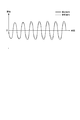
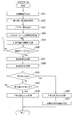
図2は、一実施形態に係る欠陥検出方法の原理を説明するための概念図である。図3は、一実施形態に係る欠陥検出方法の原理を説明するための概念図である。図4は、一実施形態に係る欠陥検出方法の原理を説明するための概念図である。図5は、一実施形態に係る欠陥検出方法の手順を示すフローチャートである。
ここでは、検出深さを固定して欠陥検出する場合に適した欠陥検出方法について説明する。例えば、異種材料の接着界面のように、内部欠陥が生じるか不明であるものの、内部欠陥が生じやすい深さを設計情報から推測可能である。そのような場合に、後述するように、内部欠陥が生じる虞がある検出深さに検出深さを設定して欠陥検出することができる。
図5に示すように、一実施形態に係る欠陥検出方法では、パルスレーザ光B2の繰り返し周波数を設定する(ステップS1)。この設定は、ユーザが知見に基づいて行ってもよいし、設計情報に基づいて制御装置203が行ってもよい。
具体的には、対象物Tの表面から検出すべき内部欠陥までの深さ(内部欠陥が生じる虞がある検出深さ)が半波長となる周波数に対応するようにパルスレーザ光B2の繰り返し周波数を設定する。例えば、図3に示す内部欠陥が存在する位置までの距離dが半波長となる周波数に対応するように繰り返し周波数を設定する。「対応するように」とは、その周波数に設定されてもよいし、その周波数に計測誤差を加味した周波数に設定されてもよいことを意味する。
ここで、内部欠陥の検出条件となる共振は、内部欠陥までの深さがパルスレーザ光B2の繰り返し周波数の半波長の整数倍の距離である場合に生じる。そのため、半波長ではなく、半波長の整数倍となる周波数に基づいて繰り返し周波数を設定してもよい。しかし、表層の小さな内部欠陥を検出する場合、上記のように、その距離が半波長に相当する繰り返し周波数で計測する方が精度の点で適している。
次に、直下に内部欠陥が存在しないと推定される位置でパルスレーザ光B2を照射した場合に得られた対象物Tの表面の振動を示す参照信号を取得する(ステップS2)。具体的には、図2に示すように、対象物Tに対して、パルスレーザ光B2を照射して対象物T中に継続的に超音波を発生させる。超音波に基づく対象物Tの表面の振動を検出装置202によって計測する。これにより、参照信号を取得することができる。なお、計測には、レーザ光B3が使用される。パルスレーザ光B2とレーザ光B3は同じ位置又は近傍位置に照射されることが好ましい。
次に、対象物の表面の振動の検出信号を取得する(ステップS3)。具体的には、直下に内部欠陥が存在するか探傷すべき位置(内部欠陥が存在する虞がある位置)でパルスレーザ光B2を照射して対象物T中に継続的に超音波を発生させる。超音波に基づく対象物Tの表面の振動を検出装置202によって計測する。これにより、検出信号を取得することができる。参照信号の取得方法と検出信号の取得方法は、位置が異なるだけで、基本的に同じである。
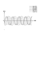
次に、ステップS2で得られた参照信号とステップS3で得られた検出信号とを比較する(ステップS4)。例えば、図4に示すように、参照信号を示す波形(破線で示す波形)と検出信号を示す波形(実線で示す波形)とを比較する。なお、参照信号と検出信号は、比較する段階で使用できればよいため、ステップS2とステップS3の順序は逆であってもよい。
参照信号と検出信号を比較して信号増幅があるか否かを判別する(ステップS5)。内部欠陥と表面との間で共振が発生している場合、共振が発生していない場合に比べて、超音波によって生じた、対象物Tの表面の振動が大きくなる。そのため、例えば、検出信号の振幅が参照信号の振幅より大きい場合には、共振している可能性が高い。なお、検出信号の振幅及び参照信号の振幅は、振動の振幅と解釈されてもよい。
ただし、両者にわずかな差異があっても検出誤差である可能性がある。そこで、例えば、検出信号の振幅が参照信号の振幅よりも所定量又は所定割合以上大きい場合には、信号増幅ありと判定されてもよい。例えば、所定量は、参照信号の振幅値が1である場合に0.1の値が設定されていてもよい。例えば、所定割合は、参照信号の10%に設定されていてもよい。これらの判別基準は、一例に過ぎず適宜変更可能である。
ここで、信号増幅があると判別した場合(ステップS5;Yes)、超音波の共振があると推定されるため、内部欠陥ありと判定する(ステップS6)。一方、信号増幅がないと判別した場合(ステップS5;No)、終了条件を満たすか否かを判別する(ステップS7)。
終了条件は、例えば、探傷すべき範囲(例えば、その層の全領域)について欠陥検出がなされたか否かの条件である。終了条件を満たすと判別した場合(ステップS7;Yes)、超音波の共振がないと推定されるため、内部欠陥なしと判定する(ステップS8)。一方、終了条件を満たさないと判別した場合(ステップS7;No)、パルスレーザ光B2とレーザ光B3の照射位置をずらして、ステップS3に戻る。
なお、図5に示す例では、内部欠陥ありと判定された場合(ステップS6)、直ちに処理を終了している。そのため、一つ目の内部欠陥がみつかった時点で処理が終了する。しかし、欠陥検出方法は、これに限られない。例えば、探傷すべき範囲について内部欠陥の有無を検出してから処理が終了してもよい。また、図5に示す例では、内部欠陥なしと判定された場合(ステップS8)、直ちに処理を終了している。そのため、探傷すべき範囲について欠陥検出が済んでいれば、処理が終了する。しかし、欠陥検出方法は、これに限られない。例えば、造形によって、次の層が形成されるまで待機して、次の層が形成されてから再びステップS3に戻って、新たな層に対して、上記と同様の処理を再開してもよい。
このように、一実施形態に係る欠陥検出方法では、ステップS5の比較結果に応じて、内部欠陥の有無を検出する。また、一実施形態に係る欠陥検出方法では、対象物Tの表面と内部欠陥との間で発生する超音波の共振の有無に基づいて内部欠陥を検出する。上記方法では、共振が発生したときのパルスレーザ光B2の照射位置に基づいて内部欠陥の平面位置を取得することができる。なお、内部欠陥の深さ位置は既知であるが、繰り返し周波数の設定値から算出することも可能である。そのため、内部欠陥があると判定された場合には、内部欠陥の位置を取得することもできる。
以下、内部欠陥の深さ位置を特定する場合に適した欠陥検出方法について、図6及び図7を参照しながら説明する。図6は、一実施形態に係る欠陥検出方法の原理を説明するための概念図である。図7は、一実施形態に係る欠陥検出方法の手順を示すフローチャートである。
図7に示すように、一実施形態に係る欠陥検出方法では、パルスレーザ光B2の繰り返し周波数を設定する(ステップS11)。なお、この時点で設定される繰り返し周波数は、周波数掃引における初期値を意味する。
繰り返し周波数は、対象物Tの探傷対象の深さ範囲に対応する半波長以下の波長となる周波数範囲内で設定されてもよい。一実施形態に係る欠陥検出方法では、かかる範囲内で周波数掃引を行うためである。そのため、繰り返し周波数の設定における無駄を低減できる。
ここで、「探傷対象の深さ範囲」とは、表面から所定の深さまでの範囲であり、表面から一以上の層を含む表層の厚さと解釈されてもよい。「対応する」とは、計測誤差を加味して表層の厚さより増減した長さであってもよいことを意味する。なお、このような繰り返し周波数の設定方法は、図5に示すステップS1において適用されてもよいし、後述する図8に示すステップS22において適用されてもよい。
パルスレーザ光B2の繰り返し周波数を掃引しながら、対象物Tの表面の振動の検出信号を取得する(ステップS12)。なお、検出信号は、連続的に繰り返し周波数を変化させたときの一つの信号データであってもよいし、離散的に繰り返し周波数を変化させたときの変化過程ごとの複数の信号データであってもよい。例えば、図6に示す例では、繰り返し周波数を所定量ずつ変化させた場合に得られる複数の検出信号(検出信号1~5)を重ね合わせて示している。
ここで、ステップS12で得られた検出信号を参照する(ステップS13)。また、参照した検出信号が示す振幅に繰り返し周波数の変化に応じた極大値があるか否かを判別する(ステップS14)。
例えば、図6では、検出信号1~5は、繰り返し周波数を変化させた順の検出信号を示している。これらの信号のうち、変化過程の検出信号3は、その前後の検出信号1、2,4,5と比べて、振幅が大きいことがわかる。この場合、検出信号3が示す振幅が繰り返し周波数の変化に応じた極大値である。なお、振幅の比較では、前後の繰り返し周波数における振幅に対して、所定量以上又は所定割合以上の増加があるか否かに基づいて極大値か否かを判別してもよい。所定量と所定割合については、図5のステップS5において説明したものと同様に考えてもよい。
極大値があると判別した場合(ステップS14;Yes)、超音波の共振があると推定されるため、内部欠陥ありと判定する(ステップS15)。この場合、内部欠陥の位置を特定する(ステップS16)具体的には、極大値に対応する繰り返し周波数に基づいて、内部欠陥の深さ位置を特定し、パルスレーザ光B2の照射位置に基づいて内部欠陥の平面位置を特定する。
一方、極大値がないと判別した場合(ステップS14;No)、終了条件を満たすか否かを判別する(ステップS17)。終了条件は、例えば、探傷すべき範囲(例えば、その層の全領域)について欠陥検出がなされたか否かの条件である。終了条件を満たすと判別した場合(ステップS17;Yes)、超音波の共振がないと推定されるため、内部欠陥なしと判定する(ステップS18)。一方、終了条件を満たさないと判別した場合(ステップS17;No)、パルスレーザ光B2とレーザ光B3の照射位置をずらして、ステップS12に戻る。
なお、図7に示す例では、一つ目の内部欠陥がみつかった時点で処理が終了する。しかし、例えば、探傷すべき範囲について内部欠陥の有無を検出してから処理が終了してもよい。また、図7に示す例では、探傷すべき範囲について欠陥検出が済んでいれば、処理が終了する。しかし、例えば、造形によって、次の層が形成されるまで待機して、次の層が形成されてから再びステップS12に戻って、新たな層に対して、上記と同様の処理を再開してもよい。
このように、上記方法では、検出信号が示す振幅に繰り返し周波数の変化に応じた極大値が存在するか否かに基づいて、内部欠陥の有無を検出する。この場合、共振が生じる周波数で振動の振幅が大きくなる傾向を利用して、内部欠陥の有無を検出することができる。また、極大値となる繰り返し周波数に基づいて内部欠陥の深さ位置を特定することができる。なお、パルスレーザ光B2の照射位置と特定した深さ位置により、内部欠陥の位置を特定することができる。
以下、3D造形しながら内部欠陥の有無を検出する場合に適した欠陥検出方法について、図8を参照しながら説明する。図8は、一実施形態に係る欠陥検出方法の手順を示すフローチャートである。
図8に示すように、一実施形態に係る欠陥検出方法では、走査範囲を設定する(ステップS21)。パルスレーザ光B2の繰り返し周波数を設定する(ステップS22)。なお、この時点で設定される繰り返し周波数は、周波数掃引における初期値を意味する。
造形装置300は、対象物Tの原料となるパウダーの敷き詰めを行う(ステップS23)。造形装置300は、エネルギービームB1の照射を開始する(ステップS24)。以後、造形装置300は、設計情報に基づいてエネルギービームB1を走査する。
内部欠陥を検出すべき計測位置の振動を計測する(ステップS25)。なお、計測位置として、エネルギービームB1が照射されていない位置を選択することが好ましい。この場合、加工時の振動や熱の影響を受けないように内部欠陥の有無を検出できるため、検出精度が向上する。振動の検出には、検出装置202が備える、共振の有無を検出するためのレーザ干渉計又はドップラ振動計が使用されてもよい。
次に、加工時の影響を受けていないかを判別するために、計測した振動が十分小さいか否かを判別する(ステップS26)。例えば、この判別において、対象物Tにおける振動が基準値以下であるか否かを判別基準としてもよい。基準値は、例えば、パルスレーザ光B2による振動の振幅の5%の振動変位に設定されてもよい。
ここで、振動が十分小さくないと判別した場合(ステップS26;No)、ステップS25に戻る。この際、ステップS25に戻る前に待機時間を設けてもよい。一方、振動が十分小さいと判別した場合(ステップS26;Yes)、検出信号を取得する(ステップS27)。
このように、一実施形態に係る欠陥検出方法では、振動が基準値以下である場合に、超音波を発生させてもよい。また、一実施形態に係る欠陥検出方法では、振動が基準値以下となるまで待機してから、内部欠陥の有無の検出を実行してもよい。これにより、検出誤差を低減できる。ステップS27の検出信号の取得方法は、上述したステップS12と基本的に同じである。すなわち、繰り返し周波数を掃引しながら検出信号を取得する。
ここで、ステップS27で得られた検出信号を参照する(ステップS28)。また、参照した検出信号が示す振幅に繰り返し周波数の変化に応じた極大値があるか否かを判別する(ステップS29)。極大値の有無の判別方法は、上述したステップS14の場合と基本的に同じである。
極大値があると判別した場合(ステップS29;Yes)、超音波の共振があると推定されるため、内部欠陥ありと判定する(ステップS30)。この場合、内部欠陥の位置を特定する(ステップS31)。内部欠陥の位置の特定方法は、上述したステップS16の場合と基本的に同じである。
一方、極大値がないと判別した場合(ステップS29;No)、終了条件を満たすか否かを判別する(ステップS32)。終了条件は、例えば、探傷すべき範囲(例えば、その層の全領域)について欠陥検出がなされたか否かの条件である。終了条件を満たすと判別した場合(ステップS32;Yes)、超音波の共振がないと推定されるため、内部欠陥なしと判定する(ステップS33)。一方、終了条件を満たさないと判別した場合(ステップS32;No)、パルスレーザ光B2とレーザ光B3の照射位置をずらして、ステップS25に戻る。
なお、図8に示す例では、一つ目の内部欠陥がみつかった時点で処理が終了する。しかし、例えば、探傷すべき範囲について内部欠陥の有無を検出してから処理が終了してもよい。また、図8に示す例では、探傷すべき範囲について欠陥検出が済んでいれば、処理が終了する。しかし、例えば、造形によって、次の層が形成されるまで待機して、次の層が形成されてから再びステップS25に戻って、新たな層に対して、上記と同様の処理を再開してもよい。
幾つかの実施形態では、付加造形によって3D造形する場合において、エネルギービームB1の軌跡に沿って後追いするように、パルスレーザ光B2を走査して、内部欠陥を検出してもよい。例えば、パルスレーザ光B2の照射位置がエネルギービームB1の照射位置より遅れて追従するように制御してもよい。しかし、加工時間に依存するエネルギービームB1の走査速度は、内部欠陥の検出時間に依存するパルスレーザ光B2の走査速度より早くてもよい。すなわち、パルスレーザ光B2は、エネルギービームB1の走査速度と同じ速度で追従するように走査しなくてもよい。
また、エネルギービームB1の走査は、パルスレーザ光B2による欠陥検出が終わるまで待機させてもよいし、走査速度を遅くしてもよい。このような制御によって、造形時間が延びたとしても、3D造形後に内部欠陥が判明して大きな手戻りが発生するよりは、時間ロスを抑えることができる場合がある。なお、追従制御の具体的な方法は、内部欠陥の検出に要する時間に応じて適宜変形可能である。
幾つかの実施形態では、付加造形によって3D造形される途中の対象物Tについて内部欠陥の有無を検出するようにしてもよい。付加造形によって3D造形する場合、3D造形途中に欠陥が発生していたとしても、3D造形後に品質検査を行うまでわからない場合がある。3D造形後に内部欠陥が判明した場合に、大きな手戻りが発生するリスクがある。この点、上記方法によれば、3D造形途中で、内部欠陥を検出するため、そのようなリスクを軽減することができる。
幾つかの実施形態では、対象物Tの表面から200μm以内の表層に位置する内部欠陥を検出してもよい。このような内部欠陥を検出する場合、表層の補修だけで対処できる場合があるため、有利である。
幾つかの実施形態では、付加造形の積層によって3D造形される造形中の対象物Tについて内部欠陥を検出した場合に、内部欠陥の直上位置で次層を形成するときに内部欠陥を修復するように次層と次層の直下層を溶融してもよい。「次層と次層の直下層を溶融する」とは、内部欠陥の上に位置する上層とともに内部欠陥を含む層を溶融することを意味する。
例えば、このような溶融を行う位置では、通常よりも多めの原料粉を供給して集中的(加熱時間又は加熱温度を増加させる)な溶融を行って、内部欠陥を修復することができる。例えば、ステップS6、S16、S31の後に、このような処理を実行してもよい。例えば、直径500μm以下の内部欠陥であれば、このような再溶融によって潰せる可能性が高い。
幾つかの実施形態では、付加造形によって3D造形する場合において、対象物Tの探傷対象の深さ範囲に相当する複数の層が積層されるごとに、対象物Tについて内部欠陥の有無を検出してもよい。「複数の層」とは、例えば、5層のように任意の数に設定される。なお、造形の完成間際では、より重点的に検査できるように通常より少ない数(例えば1層)に変更されてもよい。すなわち、このような欠陥検出方法では、積層途中では必ずしも一層ごとに内部欠陥を検出しなくてもよい。
本開示は上述した実施形態に限定されることはなく、上述した実施形態に変形を加えた形態や、複数の実施形態を適宜組み合わせた形態も含む。
(まとめ)
上記各実施形態に記載の内容は、例えば以下のように把握される。
上記各実施形態に記載の内容は、例えば以下のように把握される。
(1)本開示の一実施形態に係る欠陥検出方法は、
対象物(T)に対して、パルスレーザ光(B2)を照射して前記対象物(T)中に継続的に超音波を発生させるステップと、
前記対象物(T)の表面と内部欠陥との間で発生する前記超音波の共振の有無に基づいて、前記対象物(T)の前記内部欠陥の有無を検出するステップと、
を含む。
対象物(T)に対して、パルスレーザ光(B2)を照射して前記対象物(T)中に継続的に超音波を発生させるステップと、
前記対象物(T)の表面と内部欠陥との間で発生する前記超音波の共振の有無に基づいて、前記対象物(T)の前記内部欠陥の有無を検出するステップと、
を含む。
上記(1)に記載の方法によれば、対象物(T)の表面と内部欠陥との間で発生する超音波の共振の有無に基づいて内部欠陥を検出する。そのため、内部欠陥が対象物(T)の表層に位置する場合においても内部欠陥を検出することができる。また、パルスレーザ光(B2)を用いているため、探触子を介して対象物に超音波を発生させる方法に比べて、小さなスポット径で超音波を発生させることができる。その結果、照射方向から見た計測面が点、線、面のいずれであっても、内部欠陥を検出可能である。したがって、3D造形される対象物(T)の内部欠陥の検出に適している。
(2)幾つかの実施形態では、上記(1)に記載の方法において、
レーザ干渉計又はドップラ振動計によって前記超音波に基づく前記対象物(T)の表面の振動を検出し、前記超音波の共振の有無を検出するステップを含む。
レーザ干渉計又はドップラ振動計によって前記超音波に基づく前記対象物(T)の表面の振動を検出し、前記超音波の共振の有無を検出するステップを含む。
上記(2)に記載の方法によれば、パルスレーザ光(B2)を用いて超音波を発生させ、レーザ干渉計又はドップラ振動計を用いてその超音波に基づく振動を検出するため、内部欠陥の有無を非接触で検出することができる。
(3)幾つかの実施形態では、上記(2)に記載の方法において、
前記共振の有無を検出するステップでは、前記対象物(T)における前記パルスレーザ光(B2)の照射位置と同じ位置に前記レーザ干渉計のレーザ光(B3)を照射する。
前記共振の有無を検出するステップでは、前記対象物(T)における前記パルスレーザ光(B2)の照射位置と同じ位置に前記レーザ干渉計のレーザ光(B3)を照射する。
上記(3)に記載の方法によれば、パルスレーザ光(B2)の照射位置と同じ位置にレーザ光(B3)を照射して共振の有無を検出するため、両者の照射位置をずらして計測する場合に比べて、精度を向上させることができる。
(4)幾つかの実施形態では、上記(1)乃至(3)の何れか一つに記載の方法において、付加造形によって3D造形される途中の前記対象物(T)について前記内部欠陥の有無を検出する。
上記(4)に記載の方法によれば、3D造形途中で、内部欠陥を検出するため、大きな手戻りが発生するリスクを軽減することができる。
(5)幾つかの実施形態では、上記(1)乃至(4)の何れか一つに記載の方法において、前記対象物(T)の表面から200μm以内の表層に位置する前記内部欠陥を検出する。
上記(5)に記載の方法によれば、表面から200μm以内の表層に位置する内部欠陥を検出する。このような内部欠陥を検出する場合、表層の補修だけで対処できる場合があるため、有利である。
(6)幾つかの実施形態では、上記(1)乃至(5)の何れか一つに記載の方法において、
付加造形の積層によって3D造形される造形中の前記対象物(T)について前記内部欠陥を検出した場合に、前記内部欠陥の直上位置で次層を形成するときに前記内部欠陥を修復するように前記次層と前記次層の直下層を溶融するステップを含む。
付加造形の積層によって3D造形される造形中の前記対象物(T)について前記内部欠陥を検出した場合に、前記内部欠陥の直上位置で次層を形成するときに前記内部欠陥を修復するように前記次層と前記次層の直下層を溶融するステップを含む。
表面から深い場所に位置する内部欠陥を修復することは困難である。この点、上記(6)に記載の方法によれば、次層を形成するときに内部欠陥を修復するため、積層が進んで内部欠陥が表面から離れる前に修復を行うため、適切に修復することができる。
(7)幾つかの実施形態では、上記(1)乃至(6)の何れか一つに記載の方法において、前記内部欠陥が検出された場合に、前記共振が発生したときの前記パルスレーザ光(B2)の繰り返し周波数に基づいて、前記内部欠陥の深さ位置を特定するステップを含む。
上記(7)に記載の方法によれば、内部欠陥の深さ位置を特定することができる。なお、パルスレーザ光(B2)の照射位置と特定した深さ位置により、内部欠陥の位置を特定することができる。
(8)幾つかの実施形態では、上記(1)乃至(7)の何れか一つに記載の方法において、前記対象物(T)の表面から検出すべき前記内部欠陥までの深さが半波長となる周波数に対応するように前記パルスレーザ光(B2)の繰り返し周波数を設定するステップを含む。
共振は、内部欠陥までの深さがパルスレーザ光(B2)の繰り返し周波数の半波長の整数倍の距離である場合に生じる。しかし、表層の小さな内部欠陥を検出する場合、その距離が半波長に相当する繰り返し周波数で計測する方が精度の点で適している。この点、上記(8)に記載の方法によれば、パルスレーザ光(B2)の繰り返し周波数をそのような周波数に設定するため、表層の小さな内部欠陥を検出する場合に適している。
(9)幾つかの実施形態では、上記(1)乃至(8)の何れか一つに記載の方法において、
前記対象物(T)の表面の振動の検出信号を取得するステップと、
前記内部欠陥が存在しないと推定される位置で前記パルスレーザ光(B2)を照射した場合に得られた前記対象物(T)の表面の振動を示す参照信号と前記検出信号とを比較するステップと、
前記比較するステップの比較結果に応じて、前記内部欠陥の有無を検出するステップと、
を含む。
前記対象物(T)の表面の振動の検出信号を取得するステップと、
前記内部欠陥が存在しないと推定される位置で前記パルスレーザ光(B2)を照射した場合に得られた前記対象物(T)の表面の振動を示す参照信号と前記検出信号とを比較するステップと、
前記比較するステップの比較結果に応じて、前記内部欠陥の有無を検出するステップと、
を含む。
上記(9)に記載の方法によれば、検出深さを固定して欠陥検出する場合に適している。例えば、異種材料の接着界面のように、内部欠陥が生じるか不明であるものの、内部欠陥が生じやすい深さを設計情報から推測可能である。そのような場合に、内部欠陥が生じる虞がある検出深さに検出深さを設定して上記方法を適用することができる。
(10)幾つかの実施形態では、上記(1)乃至(9)の何れか一つに記載の方法において、
前記パルスレーザ光(B2)の繰り返し周波数を掃引しながら、前記対象物(T)の表面の振動の検出信号を取得するステップと、
前記検出信号が示す振幅に前記繰り返し周波数の変化に応じた極大値が存在するか否かに基づいて、前記内部欠陥の有無を検出するステップと、
を含む。
前記パルスレーザ光(B2)の繰り返し周波数を掃引しながら、前記対象物(T)の表面の振動の検出信号を取得するステップと、
前記検出信号が示す振幅に前記繰り返し周波数の変化に応じた極大値が存在するか否かに基づいて、前記内部欠陥の有無を検出するステップと、
を含む。
上記(10)に記載の方法によれば、検出信号が示す振幅において繰り返し周波数の変化に応じた極大値が存在するか否かに基づいて、内部欠陥の有無を検出する。この場合、共振が生じる周波数で振動の振幅が大きくなる傾向を利用して、内部欠陥の有無を検出することができる。
(11)幾つかの実施形態では、上記(10)に記載の方法において、
前記極大値に対応する前記繰り返し周波数に基づいて、前記内部欠陥の深さ位置を特定するステップを含む。
前記極大値に対応する前記繰り返し周波数に基づいて、前記内部欠陥の深さ位置を特定するステップを含む。
上記(11)に記載の方法によれば、共振が発生している可能性が高い極大値に対応する繰り返し周波数に基づいて、内部欠陥の深さ位置を特定することができる。
(12)幾つかの実施形態では、上記(1)乃至(11)の何れか一つに記載の方法において、
前記対象物(T)の探傷対象の深さ範囲に対応する半波長以下の波長となる周波数範囲内で前記パルスレーザ光(B2)の繰り返し周波数を設定するステップを含む。
前記対象物(T)の探傷対象の深さ範囲に対応する半波長以下の波長となる周波数範囲内で前記パルスレーザ光(B2)の繰り返し周波数を設定するステップを含む。
上記(12)に記載の方法によれば、内部欠陥を検出すべき対象物(T)の探傷対象の深さ範囲に応じた周波数範囲内でパルスレーザ光(B2)の繰り返し周波数を設定するため、繰り返し周波数の設定における無駄を低減できる。
(13)幾つかの実施形態では、上記(1)乃至(12)の何れか一つに記載の方法において、
前記対象物(T)に3D造形するためのエネルギービーム(B1)を照射するステップと、
前記エネルギービーム(B1)が照射されていない位置において、前記対象物(T)について前記内部欠陥の有無を検出する。
前記対象物(T)に3D造形するためのエネルギービーム(B1)を照射するステップと、
前記エネルギービーム(B1)が照射されていない位置において、前記対象物(T)について前記内部欠陥の有無を検出する。
上記(13)に記載の方法によれば、加工時の影響を受けないように内部欠陥の有無を検出するため、検出精度が向上する。
(14)幾つかの実施形態では、上記(1)乃至(13)の何れか一つに記載の方法において、
付加造形によって3D造形する場合において、前記対象物(T)の探傷対象の深さ範囲に相当する複数の層が積層されるごとに、前記対象物(T)について前記内部欠陥の有無を検出するステップを含む。
付加造形によって3D造形する場合において、前記対象物(T)の探傷対象の深さ範囲に相当する複数の層が積層されるごとに、前記対象物(T)について前記内部欠陥の有無を検出するステップを含む。
上記(14)に記載の方法によれば、3D造形の途中において適切なタイミングで内部欠陥の有無を検出することができる。また、造形途中において一層ごとに検出しないため、検出時間を短縮できる。
(15)幾つかの実施形態では、上記(1)乃至(14)の何れか一つに記載の方法において、
前記対象物(T)における振動が基準値以下である場合に、前記超音波を発生させるステップを実行する。
前記対象物(T)における振動が基準値以下である場合に、前記超音波を発生させるステップを実行する。
欠陥検出を行う場合に。3D造形の加工時の振動やその他の要因による振動が生じている場合がある。このような振動は内部欠陥の検出誤差を増加させる。この点、上記(14)に記載の方法によれば、振動が収まってから内部欠陥の検出を実行するため、検出誤差を低減することができる。
(16)幾つかの実施形態では、上記(1)乃至(15)の何れか一つに記載の方法において、
付加造形によって3D造形する場合において、エネルギービーム(B1)の軌跡に沿って後追いするように、前記パルスレーザ光(B2)を走査して、前記内部欠陥を検出する。
付加造形によって3D造形する場合において、エネルギービーム(B1)の軌跡に沿って後追いするように、前記パルスレーザ光(B2)を走査して、前記内部欠陥を検出する。
上記(16)に記載の方法によれば、3D造形しながら内部欠陥の有無を検出することができる。
(17)本開示の一実施形態に係る欠陥検出装置(200)は、
対象物(T)に対して、パルスレーザ光(B2)を照射して前記対象物(T)中に継続的に超音波を発生させるためのパルスレーザ照射装置(201)と、
前記超音波に基づく前記対象物(T)の表面の振動を検出し、前記超音波の共振の有無を検出し、前記対象物(T)の表面と内部欠陥との間で発生する前記超音波の共振の有無に基づいて、前記対象物(T)の前記内部欠陥の有無を検出するように構成された検出装置(202)と、
を備える。
対象物(T)に対して、パルスレーザ光(B2)を照射して前記対象物(T)中に継続的に超音波を発生させるためのパルスレーザ照射装置(201)と、
前記超音波に基づく前記対象物(T)の表面の振動を検出し、前記超音波の共振の有無を検出し、前記対象物(T)の表面と内部欠陥との間で発生する前記超音波の共振の有無に基づいて、前記対象物(T)の前記内部欠陥の有無を検出するように構成された検出装置(202)と、
を備える。
上記(17)に記載の構成によれば、対象物(T)の表面と内部欠陥との間で発生する超音波の共振の有無に基づいて内部欠陥を検出する。そのため、内部欠陥が対象物(T)の表層に位置する場合においても内部欠陥を検出することができる。また、パルスレーザ光(B2)を用いているため、探触子を介して対象物に超音波を発生させる方法に比べて、小さなスポット径で超音波を発生させることができる。その結果、照射方向から見た計測面が点、線、面のいずれであっても、内部欠陥を検出可能である。したがって、3D造形される対象物(T)の内部欠陥の検出に適している。
(18)本開示の一実施形態に係る造形装置(300)は、
対象物(T)を3D造形するためのビーム照射装置(100)と、
上記(17)に記載の欠陥検出装置(200)と、
を備える。
対象物(T)を3D造形するためのビーム照射装置(100)と、
上記(17)に記載の欠陥検出装置(200)と、
を備える。
上記(18)に記載の構成によれば、内部欠陥の有無を検出しながら、対象物(T)を3D造形することができる。
100 ビーム照射装置
101,204 ガルバノミラー
200 欠陥検出装置
201 パルスレーザ照射装置
202 検出装置
203 制御装置
205 ハーフミラー
300 造形装置
B1 エネルギービーム
B2 パルスレーザ光
B3 レーザ光
T 対象物
101,204 ガルバノミラー
200 欠陥検出装置
201 パルスレーザ照射装置
202 検出装置
203 制御装置
205 ハーフミラー
300 造形装置
B1 エネルギービーム
B2 パルスレーザ光
B3 レーザ光
T 対象物
Claims (18)
- 対象物に対して、パルスレーザ光を照射して前記対象物中に継続的に超音波を発生させるステップと、
前記対象物の表面と内部欠陥との間で発生する前記超音波の共振の有無に基づいて、前記対象物の前記内部欠陥の有無を検出するステップと、
を含む欠陥検出方法。 - レーザ干渉計又はドップラ振動計によって前記超音波に基づく前記対象物の表面の振動を検出し、前記超音波の共振の有無を検出するステップを含む
請求項1に記載の欠陥検出方法。 - 前記共振の有無を検出するステップでは、前記対象物における前記パルスレーザ光の照射位置と同じ位置に前記レーザ干渉計のレーザ光を照射する
請求項2に記載の欠陥検出方法。 - 付加造形によって3D造形される途中の前記対象物について前記内部欠陥の有無を検出する
請求項1乃至3の何れか一項に記載の欠陥検出方法。 - 前記対象物の表面から200μm以内の表層に位置する前記内部欠陥を検出する
請求項1乃至4の何れか一項に記載の欠陥検出方法。 - 付加造形の積層によって3D造形される造形中の前記対象物について前記内部欠陥を検出した場合に、前記内部欠陥の直上位置で次層を形成するときに前記内部欠陥を修復するように前記次層と前記次層の直下層を溶融するステップを含む
請求項1乃至5の何れか一項に記載の欠陥検出方法。 - 前記内部欠陥が検出された場合に、前記共振が発生したときの前記パルスレーザ光の繰り返し周波数に基づいて、前記内部欠陥の深さ位置を特定するステップを含む
請求項1乃至6の何れか一項に記載の欠陥検出方法。 - 前記対象物の表面から検出すべき前記内部欠陥までの深さが半波長となる周波数に対応するように前記パルスレーザ光の繰り返し周波数を設定するステップを含む
請求項1乃至7の何れか一項に記載の欠陥検出方法。 - 前記対象物の表面の振動の検出信号を取得するステップと、
前記内部欠陥が存在しないと推定される位置で前記パルスレーザ光を照射した場合に得られた前記対象物の表面の振動を示す参照信号と前記検出信号とを比較するステップと、
前記比較するステップの比較結果に応じて、前記内部欠陥の有無を検出するステップと、
を含む請求項1乃至8の何れか一項に記載の欠陥検出方法。 - 前記パルスレーザ光の繰り返し周波数を掃引しながら、前記対象物の表面の振動の検出信号を取得するステップと、
前記検出信号が示す振幅に前記繰り返し周波数の変化に応じた極大値が存在するか否かに基づいて、前記内部欠陥の有無を検出するステップと、
を含む請求項1乃至9の何れか一項に記載の欠陥検出方法。 - 前記極大値に対応する前記繰り返し周波数に基づいて、前記内部欠陥の深さ位置を特定するステップを含む
請求項10に記載の欠陥検出方法。 - 前記対象物の探傷対象の深さ範囲に対応する半波長以下の波長となる周波数範囲内で前記パルスレーザ光の繰り返し周波数を設定するステップを含む
請求項1乃至11の何れか一項に記載の欠陥検出方法。 - 前記対象物に3D造形するためのエネルギービームを照射するステップと、
前記エネルギービームが照射されていない位置において、前記対象物について前記内部欠陥の有無を検出する
請求項1乃至12の何れか一項に記載の欠陥検出方法。 - 付加造形によって3D造形する場合において、前記対象物の探傷対象の深さ範囲に相当する複数の層が積層されるごとに、前記対象物について前記内部欠陥の有無を検出するステップを含む
請求項1乃至13の何れか一項に記載の欠陥検出方法。 - 前記対象物における振動が基準値以下である場合に、前記超音波を発生させるステップを実行する
請求項1乃至14の何れか一項に記載の欠陥検出方法。 - 付加造形によって3D造形する場合において、エネルギービームの軌跡に沿って後追いするように、前記パルスレーザ光を走査して、前記内部欠陥を検出する
請求項1乃至15の何れか一項に記載の欠陥検出方法。 - 対象物に対して、パルスレーザ光を照射して前記対象物中に継続的に超音波を発生させるためのパルスレーザ照射装置と、
前記超音波に基づく前記対象物の表面の振動を検出し、前記超音波の共振の有無を検出し、前記対象物の表面と内部欠陥との間で発生する前記超音波の共振の有無に基づいて、前記対象物の前記内部欠陥の有無を検出するように構成された検出装置と、
を備える欠陥検出装置。 - 対象物を3D造形するためのビーム照射装置と、
請求項17に記載の欠陥検出装置と、
を備える造形装置。
Priority Applications (2)
| Application Number | Priority Date | Filing Date | Title |
|---|---|---|---|
| US17/802,615 US12140564B2 (en) | 2020-03-13 | 2021-02-16 | Defect detection method, defect detection device, and additive manufacturing device |
| DE112021000437.9T DE112021000437T5 (de) | 2020-03-13 | 2021-02-16 | Defektdetektionsverfahren, Defektdetektionsvorrichtung und Vorrichtung zur additiven Fertigung |
Applications Claiming Priority (2)
| Application Number | Priority Date | Filing Date | Title |
|---|---|---|---|
| JP2020043735A JP7481132B2 (ja) | 2020-03-13 | 2020-03-13 | 欠陥検出方法、欠陥検出装置及び造形装置 |
| JP2020-043735 | 2020-03-13 |
Publications (1)
| Publication Number | Publication Date |
|---|---|
| WO2021182032A1 true WO2021182032A1 (ja) | 2021-09-16 |
Family
ID=77672250
Family Applications (1)
| Application Number | Title | Priority Date | Filing Date |
|---|---|---|---|
| PCT/JP2021/005711 Ceased WO2021182032A1 (ja) | 2020-03-13 | 2021-02-16 | 欠陥検出方法、欠陥検出装置及び造形装置 |
Country Status (4)
| Country | Link |
|---|---|
| US (1) | US12140564B2 (ja) |
| JP (1) | JP7481132B2 (ja) |
| DE (1) | DE112021000437T5 (ja) |
| WO (1) | WO2021182032A1 (ja) |
Cited By (1)
| Publication number | Priority date | Publication date | Assignee | Title |
|---|---|---|---|---|
| US20220266522A1 (en) * | 2021-02-23 | 2022-08-25 | Palo Alto Research Center Incorporated | In situ thermo acoustic non-destructive testing during three-dimensional printing |
Families Citing this family (6)
| Publication number | Priority date | Publication date | Assignee | Title |
|---|---|---|---|---|
| WO2022176430A1 (ja) * | 2021-02-18 | 2022-08-25 | 国立大学法人大阪大学 | 三次元構造物の製造方法および造形装置 |
| KR20230027599A (ko) * | 2021-08-19 | 2023-02-28 | 삼성전기주식회사 | 전자부품의 결함 검출장치 및 검출방법 |
| CN116593594B (zh) * | 2023-05-18 | 2025-12-16 | 广东工业大学 | 一种多层涂层界面结合质量的超声检测方法、装置和设备 |
| CN117102508B (zh) * | 2023-08-30 | 2024-05-14 | 江苏大学 | 一种激光选区熔化缺陷调控装置及方法 |
| WO2025094329A1 (ja) * | 2023-11-01 | 2025-05-08 | 株式会社ニコン | 情報出力方法、情報出力装置、検査方法、検査装置、加工方法及び加工システム |
| TWI874280B (zh) * | 2024-09-20 | 2025-02-21 | 新加坡商先進科技新加坡有限公司 | 用於電子器件的缺陷檢驗方法和裝置 |
Citations (6)
| Publication number | Priority date | Publication date | Assignee | Title |
|---|---|---|---|---|
| JP2012163406A (ja) * | 2011-02-04 | 2012-08-30 | Toshiba Corp | 材料検査補修装置および材料検査補修方法 |
| JP2016060063A (ja) * | 2014-09-16 | 2016-04-25 | 株式会社東芝 | 積層造形装置および積層造形方法 |
| JP2017096936A (ja) * | 2015-11-19 | 2017-06-01 | ゼネラル・エレクトリック・カンパニイ | 付加製造プロセスのための非接触音響検査方法 |
| JP2017101963A (ja) * | 2015-11-30 | 2017-06-08 | 株式会社東芝 | 内部欠陥検査装置及び方法 |
| WO2018234331A1 (de) * | 2017-06-20 | 2018-12-27 | Carl Zeiss Ag | Verfahren und vorrichtung zur additiven fertigung |
| JP2019196973A (ja) * | 2018-05-09 | 2019-11-14 | 学校法人桐蔭学園 | 非接触音響解析システム及び非接触音響解析方法 |
Family Cites Families (14)
| Publication number | Priority date | Publication date | Assignee | Title |
|---|---|---|---|---|
| JPH04286933A (ja) * | 1991-03-15 | 1992-10-12 | Takenaka Komuten Co Ltd | 建物外装材の剥離検知法 |
| JPH04323553A (ja) | 1991-04-23 | 1992-11-12 | Nippon Steel Corp | 超音波共振探傷方法および装置 |
| WO2006054330A1 (ja) | 2004-11-16 | 2006-05-26 | H & B System Co., Ltd. | 共振現象を利用した超音波探査方法およびその装置 |
| WO2007128138A1 (en) | 2006-05-10 | 2007-11-15 | National Research Council Of Canada | Method of assessing bond integrity in bonded structures |
| JP2011257163A (ja) * | 2010-06-07 | 2011-12-22 | Panasonic Corp | レーザ超音波検査方法およびレーザ超音波検査装置 |
| JP6121873B2 (ja) * | 2013-10-23 | 2017-04-26 | 株式会社東芝 | レーザ超音波検査装置及び方法 |
| CN103543208B (zh) * | 2013-10-24 | 2015-07-08 | 大连理工大学 | 基于频谱分析原理减小tofd检测近表面盲区的方法 |
| US9989482B2 (en) | 2016-02-16 | 2018-06-05 | General Electric Company | Methods for radiographic and CT inspection of additively manufactured workpieces |
| US10675684B2 (en) | 2016-04-29 | 2020-06-09 | Hexcel Corporation | Metal AM process with in situ inspection |
| US10942152B2 (en) | 2016-06-21 | 2021-03-09 | Shimadzu Corporation | Defect inspection device and method |
| US20180292355A1 (en) * | 2017-04-05 | 2018-10-11 | General Electric Company | System and method for authenticating components |
| US10710159B2 (en) | 2017-09-06 | 2020-07-14 | General Electric Company | Apparatus and method for additive manufacturing with real-time and in-situ adjustment of growth parameters |
| JP7609702B2 (ja) * | 2021-05-11 | 2025-01-07 | 三菱重工業株式会社 | 欠陥検出方法 |
| JP7609709B2 (ja) * | 2021-05-31 | 2025-01-07 | 三菱重工業株式会社 | 欠陥検出装置及び欠陥検出方法 |
-
2020
- 2020-03-13 JP JP2020043735A patent/JP7481132B2/ja active Active
-
2021
- 2021-02-16 WO PCT/JP2021/005711 patent/WO2021182032A1/ja not_active Ceased
- 2021-02-16 DE DE112021000437.9T patent/DE112021000437T5/de active Pending
- 2021-02-16 US US17/802,615 patent/US12140564B2/en active Active
Patent Citations (6)
| Publication number | Priority date | Publication date | Assignee | Title |
|---|---|---|---|---|
| JP2012163406A (ja) * | 2011-02-04 | 2012-08-30 | Toshiba Corp | 材料検査補修装置および材料検査補修方法 |
| JP2016060063A (ja) * | 2014-09-16 | 2016-04-25 | 株式会社東芝 | 積層造形装置および積層造形方法 |
| JP2017096936A (ja) * | 2015-11-19 | 2017-06-01 | ゼネラル・エレクトリック・カンパニイ | 付加製造プロセスのための非接触音響検査方法 |
| JP2017101963A (ja) * | 2015-11-30 | 2017-06-08 | 株式会社東芝 | 内部欠陥検査装置及び方法 |
| WO2018234331A1 (de) * | 2017-06-20 | 2018-12-27 | Carl Zeiss Ag | Verfahren und vorrichtung zur additiven fertigung |
| JP2019196973A (ja) * | 2018-05-09 | 2019-11-14 | 学校法人桐蔭学園 | 非接触音響解析システム及び非接触音響解析方法 |
Cited By (1)
| Publication number | Priority date | Publication date | Assignee | Title |
|---|---|---|---|---|
| US20220266522A1 (en) * | 2021-02-23 | 2022-08-25 | Palo Alto Research Center Incorporated | In situ thermo acoustic non-destructive testing during three-dimensional printing |
Also Published As
| Publication number | Publication date |
|---|---|
| US20230135790A1 (en) | 2023-05-04 |
| DE112021000437T5 (de) | 2022-10-13 |
| US12140564B2 (en) | 2024-11-12 |
| JP2021143972A (ja) | 2021-09-24 |
| JP7481132B2 (ja) | 2024-05-10 |
Similar Documents
| Publication | Publication Date | Title |
|---|---|---|
| JP7481132B2 (ja) | 欠陥検出方法、欠陥検出装置及び造形装置 | |
| CN105102173B (zh) | 焊接部检查装置及其检查方法 | |
| JP5651533B2 (ja) | 溶接検査方法および装置 | |
| Yamamoto et al. | Defect detection in thick weld structure using welding in-process laser ultrasonic testing system | |
| US20210197287A1 (en) | Integrated inspection system for 3d printing process based on thermal image and laser ultrasound wave and 3d printing system having the same | |
| CN118192477B (zh) | 一种用于塑焊一体机的设备智能控制系统及方法 | |
| JP5104833B2 (ja) | 構造物内部状態計測システム及び構造物内部状態計測方法 | |
| JP2011257163A (ja) | レーザ超音波検査方法およびレーザ超音波検査装置 | |
| JP2022537449A (ja) | 検査型製造システム及び方法 | |
| CN110702686B (zh) | 基于相干成像的定向能量沉积过程无损检测设备及方法 | |
| EP2605008A1 (en) | A method for inspection of a weld and an inspection apparatus for inspection of a weld | |
| US20220146252A1 (en) | Non-Contact Non-Destructive Testing Method and System | |
| KR102285477B1 (ko) | 비접촉 광음향 영상을 이용한 고주파 열처리 금속 내부의 비파괴 결함 검사 장치 및 방법 | |
| JP7039371B2 (ja) | レーザ励起超音波発生装置、レーザ超音波検査装置、及びレーザ超音波検査方法 | |
| JP2015081858A (ja) | レーザ超音波検査装置及び方法 | |
| WO2022254805A1 (ja) | 欠陥検出装置及び欠陥検出方法 | |
| Nomura et al. | In-situ detection of weld defect during the welding process by laser ultrasonic technique | |
| JP6934440B2 (ja) | 超音波検査方法、超音波検査装置及び超音波検査方法を用いた高圧燃料供給ポンプの製造方法 | |
| JP6591282B2 (ja) | レーザ超音波検査方法、接合方法、レーザ超音波検査装置、および接合装置 | |
| JP7609702B2 (ja) | 欠陥検出方法 | |
| JP7170223B2 (ja) | 溶接判定装置、溶接装置、および、溶接判定方法 | |
| CN116329740B (zh) | 一种激光熔焊原位监测与工艺控制的方法和装置 | |
| US5796004A (en) | Method and apparatus for exciting bulk acoustic wave | |
| CN110954018A (zh) | 一种光学相干断层扫描检测系统 | |
| JP6877312B2 (ja) | 付加製造方法及び付加製造システム |
Legal Events
| Date | Code | Title | Description |
|---|---|---|---|
| 121 | Ep: the epo has been informed by wipo that ep was designated in this application |
Ref document number: 21768635 Country of ref document: EP Kind code of ref document: A1 |
|
| 122 | Ep: pct application non-entry in european phase |
Ref document number: 21768635 Country of ref document: EP Kind code of ref document: A1 |