WO2021181729A1 - 希薄溶液製造装置 - Google Patents
希薄溶液製造装置 Download PDFInfo
- Publication number
- WO2021181729A1 WO2021181729A1 PCT/JP2020/034828 JP2020034828W WO2021181729A1 WO 2021181729 A1 WO2021181729 A1 WO 2021181729A1 JP 2020034828 W JP2020034828 W JP 2020034828W WO 2021181729 A1 WO2021181729 A1 WO 2021181729A1
- Authority
- WO
- WIPO (PCT)
- Prior art keywords
- liquid
- pipe
- dilute solution
- pump
- degassing
- Prior art date
- Legal status (The legal status is an assumption and is not a legal conclusion. Google has not performed a legal analysis and makes no representation as to the accuracy of the status listed.)
- Ceased
Links
Images
Classifications
-
- C—CHEMISTRY; METALLURGY
- C02—TREATMENT OF WATER, WASTE WATER, SEWAGE, OR SLUDGE
- C02F—TREATMENT OF WATER, WASTE WATER, SEWAGE, OR SLUDGE
- C02F1/00—Treatment of water, waste water, or sewage
- C02F1/68—Treatment of water, waste water, or sewage by addition of specified substances, e.g. trace elements, for ameliorating potable water
- C02F1/685—Devices for dosing the additives
- C02F1/686—Devices for dosing liquid additives
-
- C—CHEMISTRY; METALLURGY
- C02—TREATMENT OF WATER, WASTE WATER, SEWAGE, OR SLUDGE
- C02F—TREATMENT OF WATER, WASTE WATER, SEWAGE, OR SLUDGE
- C02F1/00—Treatment of water, waste water, or sewage
- C02F1/68—Treatment of water, waste water, or sewage by addition of specified substances, e.g. trace elements, for ameliorating potable water
-
- C—CHEMISTRY; METALLURGY
- C02—TREATMENT OF WATER, WASTE WATER, SEWAGE, OR SLUDGE
- C02F—TREATMENT OF WATER, WASTE WATER, SEWAGE, OR SLUDGE
- C02F1/00—Treatment of water, waste water, or sewage
- C02F1/008—Control or steering systems not provided for elsewhere in subclass C02F
-
- C—CHEMISTRY; METALLURGY
- C02—TREATMENT OF WATER, WASTE WATER, SEWAGE, OR SLUDGE
- C02F—TREATMENT OF WATER, WASTE WATER, SEWAGE, OR SLUDGE
- C02F1/00—Treatment of water, waste water, or sewage
- C02F1/20—Treatment of water, waste water, or sewage by degassing, i.e. liberation of dissolved gases
-
- F—MECHANICAL ENGINEERING; LIGHTING; HEATING; WEAPONS; BLASTING
- F04—POSITIVE - DISPLACEMENT MACHINES FOR LIQUIDS; PUMPS FOR LIQUIDS OR ELASTIC FLUIDS
- F04B—POSITIVE-DISPLACEMENT MACHINES FOR LIQUIDS; PUMPS
- F04B23/00—Pumping installations or systems
-
- F—MECHANICAL ENGINEERING; LIGHTING; HEATING; WEAPONS; BLASTING
- F04—POSITIVE - DISPLACEMENT MACHINES FOR LIQUIDS; PUMPS FOR LIQUIDS OR ELASTIC FLUIDS
- F04B—POSITIVE-DISPLACEMENT MACHINES FOR LIQUIDS; PUMPS
- F04B53/00—Component parts, details or accessories not provided for in, or of interest apart from, groups F04B1/00 - F04B23/00 or F04B39/00 - F04B47/00
- F04B53/06—Venting
-
- H—ELECTRICITY
- H10—SEMICONDUCTOR DEVICES; ELECTRIC SOLID-STATE DEVICES NOT OTHERWISE PROVIDED FOR
- H10P—GENERIC PROCESSES OR APPARATUS FOR THE MANUFACTURE OR TREATMENT OF DEVICES COVERED BY CLASS H10
- H10P52/00—Grinding, lapping or polishing of wafers, substrates or parts of devices
-
- C—CHEMISTRY; METALLURGY
- C02—TREATMENT OF WATER, WASTE WATER, SEWAGE, OR SLUDGE
- C02F—TREATMENT OF WATER, WASTE WATER, SEWAGE, OR SLUDGE
- C02F2103/00—Nature of the water, waste water, sewage or sludge to be treated
- C02F2103/02—Non-contaminated water, e.g. for industrial water supply
- C02F2103/04—Non-contaminated water, e.g. for industrial water supply for obtaining ultra-pure water
-
- C—CHEMISTRY; METALLURGY
- C02—TREATMENT OF WATER, WASTE WATER, SEWAGE, OR SLUDGE
- C02F—TREATMENT OF WATER, WASTE WATER, SEWAGE, OR SLUDGE
- C02F2209/00—Controlling or monitoring parameters in water treatment
- C02F2209/005—Processes using a programmable logic controller [PLC]
-
- C—CHEMISTRY; METALLURGY
- C02—TREATMENT OF WATER, WASTE WATER, SEWAGE, OR SLUDGE
- C02F—TREATMENT OF WATER, WASTE WATER, SEWAGE, OR SLUDGE
- C02F2209/00—Controlling or monitoring parameters in water treatment
- C02F2209/04—Oxidation reduction potential [ORP]
-
- C—CHEMISTRY; METALLURGY
- C02—TREATMENT OF WATER, WASTE WATER, SEWAGE, OR SLUDGE
- C02F—TREATMENT OF WATER, WASTE WATER, SEWAGE, OR SLUDGE
- C02F2209/00—Controlling or monitoring parameters in water treatment
- C02F2209/05—Conductivity or salinity
-
- C—CHEMISTRY; METALLURGY
- C02—TREATMENT OF WATER, WASTE WATER, SEWAGE, OR SLUDGE
- C02F—TREATMENT OF WATER, WASTE WATER, SEWAGE, OR SLUDGE
- C02F2209/00—Controlling or monitoring parameters in water treatment
- C02F2209/40—Liquid flow rate
Definitions
- the present invention is to produce a dilute solution for producing a dilute solution of the substance by adding a small amount of a second liquid containing a conductivity-imparting substance, an oxidation-reduction potential adjusting substance, or the like to a first liquid such as ultrapure water.
- a second liquid containing a conductivity-imparting substance, an oxidation-reduction potential adjusting substance, or the like
- a first liquid such as ultrapure water.
- a cleaning solution used for wafer processing in the electronic industry field a solution obtained by adding a conductivity-imparting substance or an oxidation-reduction potential adjusting substance to ultrapure water is used.
- Patent Documents 1 and 2 the conductivity-imparting substance and the redox potential adjusting substance are added to the ultrapure water by a pump.
- the conductivity-imparting substance or redox potential adjusting substance is a substance that easily vaporizes, air bubbles of the substance tend to accumulate in the pump.
- an extremely low flow rate pump is vulnerable to clogging due to air bubbles, and when air bubbles accumulate, it becomes impossible to discharge a fixed amount from the pump.
- a dilute solution having a specified concentration can be stably produced by adding a small amount of a second liquid containing a conductivity-imparting substance or an oxidation-reduction potential adjusting substance to a first liquid such as ultrapure water.
- An object of the present invention is to provide a dilute solution manufacturing apparatus.
- the dilute solution producing apparatus of the first invention is a dilute solution of the second liquid by adding a second liquid containing at least one of a conductivity-imparting substance and an oxidation-reduction potential adjusting substance to the first liquid.
- a first pipe for flowing the first liquid a pump for adding the second liquid through the second pipe into the first pipe, and the pump.
- the dilute solution producing apparatus of the second invention is a dilute solution of the second liquid by adding a second liquid containing at least one of a conductivity-imparting substance and an oxidation-reduction potential adjusting substance to the first liquid.
- a first pipe for flowing the first liquid a pump for adding the second liquid through the second pipe into the first pipe, and the pump.
- the flow meter provided on the downstream side of the pump in the second pipe and the detected value of the flow meter fluctuate by a predetermined value or more in the dilute solution manufacturing apparatus provided with the degassing mechanism from the pump. It is characterized by including a degassing mechanism control means for operating the degassing mechanism.
- a tank for storing the second liquid is provided, the second pipe is connected to the tank, and the degassing mechanism is a second gas mixed from the pump.
- a degassing pipe for guiding the liquid of the above to the tank and a valve provided in the degassing pipe are provided, and the control means controls the opening and closing of the valve.
- examples of the conductivity-imparting substance and the redox potential adjusting substance include, but are not limited to, ammonia, carbon dioxide, hydrogen peroxide, ozone, and the like.
- gas is accumulated in the pump for adding the second liquid to the first liquid such as ultrapure water, and the discharge amount of the pump is reduced, or the pump is diluted accordingly.
- the conductivity, specific resistance or oxidation-reduction potential of the solution fluctuates by a predetermined value or more from the stable values up to that point, the degassing mechanism is activated to degas the pump, and the pump discharge amount is restored. This makes it possible to stably supply a dilute solution having a specified concentration.
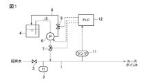
- FIG. 1 is a configuration diagram of a dilute solution manufacturing apparatus according to an embodiment.
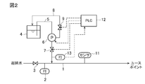
- FIG. 2 is a block diagram of a dilute solution manufacturing apparatus according to another embodiment.
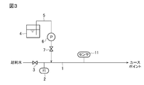
- FIG. 3 is a configuration diagram of a dilute solution manufacturing apparatus according to a comparative example.
- FIG. 1 shows an embodiment of the first invention.
- the ultrapure water as the first liquid is sent to the use point via the first pipe 1 having the flow meter 2 and the valve 3, and on the way, the second liquid in the tank 4 becomes the second liquid. It is added via the pipe 5, the pump 6, and the flow rate adjusting valve 7.
- a degassing pipe 8 is provided so as to return the second liquid containing the gas generated by the pump 6 to the tank 4.
- a gas vent valve 9 is provided in the gas vent pipe 8. The degassing valve 9 may be provided in the middle of the degassing pipe 8, and may be provided at the upstream end or the downstream end.
- a solution of the above-mentioned conductivity-imparting substance or redox potential adjusting substance is stored in the tank 4.
- a water quality sensor as a water quality detector composed of a conductivity meter, a resistivity meter, or a redox potential meter (ORP meter) on the downstream side of the connection portion (confluence portion) of the second pipe 5 in the first pipe 1. 11 is provided.
- the detection signal of the water quality sensor 11 is input to the control device (in this embodiment, PLC (programmable logic controller)) 12.
- the control device 12 controls the pump 6, the flow rate adjusting valve 7, and the degassing valve 9.
- the discharge amount of the pump 6 decreases and the detection value of the sensor 11 increases. It fluctuates by a predetermined value or more (for example, 5% or more) from the stable value (value according to the target value) up to that point.
- the control device 12 opens the degassing valve 9 for a predetermined time, returns the second liquid mixed with gas from the pump 6 to the tank 4, and degass after the elapse of the predetermined time. Return the valve 9 to closed.
- the discharge amount of the pump 6 returns to the steady amount, and the ultrapure water containing the second liquid having the specified concentration is sent to the use point.
- the case where the sensor detection value fluctuates by 5% or more is given as an example, but the present invention is not limited to this.
- the fluctuation value of the sensor detection value a value selected from the range of 1 to 10%, particularly 3 to 7% may be adopted.
- FIG. 2 shows an embodiment of the second invention.
- the flow meter 13 is installed on the downstream side of the second pipe 5 with respect to the pump 6 (in this embodiment, the downstream side of the flow rate adjusting valve 7).
- the detection signal of the flow meter 13 is input to the control device 12.
- the control device 12 opens the degassing valve 9 for a predetermined time to degas.
- Other configurations and operations are the same as in FIG. 1, and the same reference numerals indicate the same parts.
- ultrapure water containing a second liquid having a specified concentration is stably sent to the point of use.
- Example 1 Using the dilute solution manufacturing apparatus shown in FIG. 1, a 29% NH 3 solution was pumped from the tank 4 and added to the ultrapure water in the pipe 1 passing water at 60 L / min, and the conductivity was 3 ⁇ S. A solution at / cm was prepared.
- the sensor 11 used is a conductivity meter. When the conductivity drops by 5% from the set value, the degassing valve 9 is opened for 5 seconds to release the gas, and then the degassing valve 9 is closed to return to the normal state. Although this test was continued for 30 days, the conductivity detected by the conductivity meter 11 did not decrease by 10% or more from the set value.
- Example 2 The operation was carried out in the same manner as in Example 1 except that a 29% NH 3 solution was added so as to have a conductivity of 1500 ⁇ S / cm. Although this test was continued for 30 days, the conductivity detected by the conductivity meter 11 did not decrease by 10% or more from the set value.
- Example 3 The operation was carried out in the same manner as in Example 1 except that the flow rate of ultrapure water was set to 3 L / min. Although this test was continued for 30 days, the conductivity detected by the conductivity meter 11 did not decrease by 10% or more from the set value.
- Example 4 Using dilute solutions manufacturing apparatus shown in FIG. 2, was added 29% NH 3 solution with ultrapure water flow rate same as in Example 1 (60L / min) and the target conductivity (3 ⁇ S / cm).
- the degassing valve 9 when the detected flow rate of the flow meter 13 detected a flow rate of 0, the degassing valve 9 was opened for 5 seconds to release the gas, and then the degassing valve 9 was closed to return to the normal state. Although this test was continued for 30 days, the conductivity detected by the conductivity meter 11 did not decrease by 10% or more from the set value.
- Example 5 Using the device shown in FIG. 1, the liquid in the tank 4 was set to a 60% H 2 O 2 solution, the ultrapure water flow rate was set to 60 L / min, a redox potential meter was used as the sensor 11, and the H 2 O 2 concentration was 0.5 ppb. H 2 O 2 containing ultrapure water was sent to the point of use.
- the degassing valve 9 When the detected redox potential of the redox potential meter 11 dropped by 5% from the set value, the degassing valve 9 was opened for 5 seconds to release the gas, and then the degassing valve 9 was closed to return to the normal state.
- Example 6 The operation was carried out in the same manner as in Example 5 except that H 2 O 2 was added so that the concentration of H 2 O 2 in the ultrapure water was 1000 ppb. Although this test was continued for 30 days, the redox potential detected by the redox potential meter 11 did not decrease by 10% or more from the set value.
- Example 7 The operation was carried out in the same manner as in Example 5 except that the ultrapure water flow rate was set to 3 L / min. Although this test was continued for 30 days, the redox potential detected by the redox potential meter 11 did not decrease by 10% or more from the set value.
- Example 8 Using dilute solutions manufacturing apparatus shown in FIG. 2, was operated to water ultrapure water concentration of H 2 O 2 0.5ppb in the same ultra pure water flow rate and the target oxidation reduction potential of Example 5.
- the degassing valve 9 when the detected flow rate of the flow meter 13 detects a flow rate of 0, the degassing valve 9 is opened for 5 seconds to release the gas, and then the degassing valve 9 is closed to return to the normal state. Although this test was continued for 30 days, the redox potential detected by the redox potential meter 11 did not decrease by 10% or more from the set value.
- ultrapure water containing NH 3 or H 2 O 2 at a specified dilute concentration can be stably delivered to the point of use.
Landscapes
- Engineering & Computer Science (AREA)
- Chemical & Material Sciences (AREA)
- Mechanical Engineering (AREA)
- General Engineering & Computer Science (AREA)
- Water Supply & Treatment (AREA)
- Environmental & Geological Engineering (AREA)
- Hydrology & Water Resources (AREA)
- Life Sciences & Earth Sciences (AREA)
- Organic Chemistry (AREA)
- Health & Medical Sciences (AREA)
- Medicinal Chemistry (AREA)
- Cleaning Or Drying Semiconductors (AREA)
- Accessories For Mixers (AREA)
- Details Of Reciprocating Pumps (AREA)
Abstract
超純水等の第1の液体に、導電性付与物質又は酸化還元電位調整物質を含む第2の液体を微量添加して規定濃度の希薄溶液を安定して製造することができる希薄溶液製造装置を提供する。第1の液体に対して導電性付与物質及び酸化還元電位調整物質の少なくとも一つを含む第2の液体を添加することで該第2の液体の希薄溶液を製造する希薄溶液の製造装置であって、前記第1の液体を流す第1の配管1と、前記第1の配管1内に第2の配管5を通じて前記第2の液体を添加するポンプ6と、該ポンプ6からのガス抜き配管8と、導電率計、比抵抗計又は酸化還元電位計よりなる水質センサ11と、該水質センサ11の水質検出値が所定値以上変動したときにガス抜き弁9を開く制御装置12とを備えた希薄溶液製造装置。
Description
本発明は、超純水等の第1の液体に、導電性付与物質又は酸化還元電位調整物質等を含む第2の液体を少量添加して該物質の希薄溶液を製造するための希薄溶液製造装置に関する。
電子産業分野のウエハ処理に使用される洗浄溶液として、超純水に導電性付与物質や酸化還元電位調整物質を添加した溶液が使用されている。
その際に、導電性付与物質や酸化還元電位調整物質はポンプで超純水に添加される(特許文献1,2)。
導電性付与物質や酸化還元電位調整物質が気化しやすい物質の場合、物質の気泡がポンプ内に溜り易い。特に、極低流量のポンプは気泡による詰りに弱く、気泡が溜まるとポンプから定量吐出ができなくなる。
本発明は、超純水等の第1の液体に、導電性付与物質又は酸化還元電位調整物質を含む第2の液体を微量添加して規定濃度の希薄溶液を安定して製造することができる希薄溶液製造装置を提供することを目的とする。
第1発明の希薄溶液製造装置は、第1の液体に対して導電性付与物質及び酸化還元電位調整物質の少なくとも一つを含む第2の液体を添加することで該第2の液体の希薄溶液を製造する希薄溶液の製造装置であって、前記第1の液体を流す第1の配管と、前記第1の配管内に第2の配管を通じて前記第2の液体を添加するポンプと、該ポンプからのガス抜き機構とを備えた希薄溶液製造装置において、前記第1の配管のうち前記第2の配管の接続部よりも下流側に設けられた、導電率計、比抵抗計又は酸化還元電位計よりなる水質検出計と、該水質検出計の水質検出値が所定値以上変動したときに前記ガス抜き機構を作動させるガス抜き機構制御手段とを備えたことを特徴とする。
第2発明の希薄溶液製造装置は、第1の液体に対して導電性付与物質及び酸化還元電位調整物質の少なくとも一つを含む第2の液体を添加することで該第2の液体の希薄溶液を製造する希薄溶液の製造装置であって、前記第1の液体を流す第1の配管と、前記第1の配管内に第2の配管を通じて前記第2の液体を添加するポンプと、該ポンプからのガス抜き機構とを備えた希薄溶液製造装置において、前記第2の配管のうち前記ポンプよりも下流側に設けられた流量計と、該流量計の検出値が所定値以上変動したときに前記ガス抜き機構を作動させるガス抜き機構制御手段とを備えたことを特徴とする。
本発明の一態様では、前記第2の液体を貯留するタンクを備えており、前記第2の配管は該タンクに接続されており、前記ガス抜き機構は、前記ポンプからガスが混入した第2の液体を該タンクに導くためのガス抜き配管と、該ガス抜き配管に設けられた弁とを備えており、前記制御手段は、該弁の開閉を制御するものである。
本発明において、導電性付与物質、酸化還元電位調整物質としては、アンモニア、二酸化炭素、過酸化水素、オゾンなどが例示されるが、これらに限定されない。
本発明の希薄溶液製造装置によると、超純水等の第1の液体に第2の液体を添加するためのポンプにガスが溜まって、ポンプの吐出量が低下したり、あるいはそれにより、希薄溶液の導電率、比抵抗又は酸化還元電位がそれまでの安定した値から所定以上変動した場合、ガス抜き機構が作動してポンプからガス抜きが行われ、ポンプ吐出量が回復する。これにより、規定濃度の希薄溶液を安定して供給することが可能となる。
以下、図面を参照して実施の形態について説明する。
図1は第1発明の実施の形態を示すものである。
第1の液体としての超純水は、流量計2及びバルブ3を有した第1の配管1を介してユースポイントに送水され、その途中で、タンク4内の第2の液体が第2の配管5、ポンプ6及び流量調整弁7を介して添加される。ポンプ6で発生したガスを含む第2の液体をタンク4に戻すようにガス抜き配管8が設けられている。ガス抜き配管8にガス抜き弁9が設けられている。ガス抜き弁9は、ガス抜き配管8の途中に設けられてもよく、上流端又は下流端に設けられてもよい。
タンク4内には、前述の導電性付与物質又は酸化還元電位調整物質の溶液が貯留されている。
第1の配管1のうち、第2の配管5の接続部(合流部)よりも下流側に導電率計、比抵抗計又は酸化還元電位計(ORP計)よりなる水質検出計としての水質センサ11が設けられている。該水質センサ11の検出信号が制御装置(この実施の形態では、PLC(プログラマブルロジックコントローラ))12に入力されている。制御装置12によってポンプ6、流量調整弁7及びガス抜き弁9が制御される。
このように構成された希薄溶液製造装置において、定常時にあっては、第1の配管1内を超純水が定流量にて流れ、第2の配管5内を第2の液体が定流量にて流れ、第2の液体が規定濃度となるように添加された希薄溶液がユースポイントに送水される。
ポンプ6に、アンモニア、炭酸ガス、過酸化水素、オゾンなど、第2の液体から分離したガスやエアなどのガスが溜ってくると、ポンプ6の吐出量が減少し、センサ11の検出値がそれまでの安定した値(目標値通りの値)から所定以上(例えば5%以上)変動する。このような水質変動が検出された場合、制御装置12はガス抜き弁9を所定時間開とし、ガスが混ざった第2の液体をポンプ6からタンク4に戻し、該所定時間経過後、ガス抜き弁9を閉に戻す。これにより、ポンプ6の吐出量が定常量に戻り、規定濃度の第2の液体を含んだ超純水がユースポイントに送水される。
上記説明では、センサ検出値が5%以上変動した場合を例として挙げているが、これに限定されるものではない。センサ検出値の変動値は、通常は1~10%特に3~7%の範囲から選択した値を採用すればよい。
次に説明する第2発明の実施の形態の流量計13においても同様である。
次に説明する第2発明の実施の形態の流量計13においても同様である。
図2は第2発明の実施の形態を示している。この実施の形態では、第2の配管5のうち前記ポンプ6よりも下流側(この実施の形態では流量調整弁7の下流側)に流量計13が設置されている。流量計13の検出信号が制御装置12に入力されている。
制御装置12は、該流量計13の検出流量がそれまでの安定した値よりも5%以上変動した場合に、ガス抜き弁9を所定時間開とし、ガス抜きを行う。その他の構成及び作用は図1と同じであり、同一符号は同一部分を示している。
この実施の形態によっても、規定濃度の第2の液体を含む超純水が安定してユースポイントに送水される。
以下に実施例及び比較例について説明する。
[実施例1]
図1に示す希薄溶液製造装置を用い、タンク4から29%NH3溶液をポンプ6により送液し、60L/minで通水している配管1内の超純水に添加し、導電率3μS/cmとなる溶液を作製した。使用したセンサ11は導電率計である。導電率が設定値から5%下がった時点でガス抜き弁9を5秒間開けてガスを抜き、その後ガス抜き弁9を閉めて通常状態に戻す。本試験を30日間続けたが、導電率計11で検出される導電率が設定値から10%以上低下することはなかった。
図1に示す希薄溶液製造装置を用い、タンク4から29%NH3溶液をポンプ6により送液し、60L/minで通水している配管1内の超純水に添加し、導電率3μS/cmとなる溶液を作製した。使用したセンサ11は導電率計である。導電率が設定値から5%下がった時点でガス抜き弁9を5秒間開けてガスを抜き、その後ガス抜き弁9を閉めて通常状態に戻す。本試験を30日間続けたが、導電率計11で検出される導電率が設定値から10%以上低下することはなかった。
[実施例2]
29%NH3溶液を導電率1500μS/cmとなるように添加したこと以外は実施例1と同様にして運転を行った。本試験を30日間続けたが、導電率計11で検出される導電率が設定値から10%以上低下することはなかった。
29%NH3溶液を導電率1500μS/cmとなるように添加したこと以外は実施例1と同様にして運転を行った。本試験を30日間続けたが、導電率計11で検出される導電率が設定値から10%以上低下することはなかった。
[実施例3]
超純水の通水量を3L/minとしたこと以外は実施例1と同様にして運転を行った。本試験を30日間続けたが、導電率計11で検出される導電率が設定値から10%以上低下することはなかった。
超純水の通水量を3L/minとしたこと以外は実施例1と同様にして運転を行った。本試験を30日間続けたが、導電率計11で検出される導電率が設定値から10%以上低下することはなかった。
[実施例4]
図2に示す希薄溶液製造装置を用い、実施例1と同一の超純水流量(60L/min)及び目標導電率(3μS/cm)にて29%NH3溶液を添加した。
図2に示す希薄溶液製造装置を用い、実施例1と同一の超純水流量(60L/min)及び目標導電率(3μS/cm)にて29%NH3溶液を添加した。
この実施例4では、流量計13の検出流量が流量0を検知した時点でガス抜き弁9を5秒間開けてガスを抜き、その後ガス抜き弁9を閉めて通常状態に戻すように制御した。本試験を30日間続けたが、導電率計11で検出される導電率が設定値から10%以上低下することはなかった。
[実施例5]
図1の装置を用い、タンク4内の液体を60%H2O2溶液とし、超純水流量を60L/minとし、センサ11として酸化還元電位計を用い、H2O2濃度0.5ppbのH2O2含有超純水をユースポイントに送水するようにした。酸化還元電位計11の検出酸化還元電位が設定値から5%下がった時点でガス抜き弁9を5秒間開けてガスを抜き、その後ガス抜き弁9を閉めて通常状態に戻すように制御した。
図1の装置を用い、タンク4内の液体を60%H2O2溶液とし、超純水流量を60L/minとし、センサ11として酸化還元電位計を用い、H2O2濃度0.5ppbのH2O2含有超純水をユースポイントに送水するようにした。酸化還元電位計11の検出酸化還元電位が設定値から5%下がった時点でガス抜き弁9を5秒間開けてガスを抜き、その後ガス抜き弁9を閉めて通常状態に戻すように制御した。
本試験を30日間続けたが、酸化還元電位計11で検出される酸化還元電位が設定値から10%以上低下することはなかった。
[実施例6]
超純水中のH2O2濃度が1000ppbとなるようにH2O2を添加したこと以外は実施例5と同様にして運転を行った。本試験を30日間続けたが、酸化還元電位計11で検出される酸化還元電位が設定値から10%以上低下することはなかった。
超純水中のH2O2濃度が1000ppbとなるようにH2O2を添加したこと以外は実施例5と同様にして運転を行った。本試験を30日間続けたが、酸化還元電位計11で検出される酸化還元電位が設定値から10%以上低下することはなかった。
[実施例7]
超純水流量を3L/minとしたこと以外は実施例5と同様にして運転した。本試験を30日間続けたが、酸化還元電位計11で検出される酸化還元電位が設定値から10%以上低下することはなかった。
超純水流量を3L/minとしたこと以外は実施例5と同様にして運転した。本試験を30日間続けたが、酸化還元電位計11で検出される酸化還元電位が設定値から10%以上低下することはなかった。
[実施例8]
図2に示す希薄溶液製造装置を用い、実施例5と同一の超純水流量及び目標酸化還元電位にてH2O2濃度0.5ppbの超純水を送水するよう運転した。この実施例8では、流量計13の検出流量が流量0を検知した時点でガス抜き弁9を5秒間開けてガスを抜き、その後ガス抜き弁9を閉めて通常状態に戻すように制御した。本試験を30日間続けたが、酸化還元電位計11で検出される酸化還元電位が設定値から10%以上低下することはなかった。
図2に示す希薄溶液製造装置を用い、実施例5と同一の超純水流量及び目標酸化還元電位にてH2O2濃度0.5ppbの超純水を送水するよう運転した。この実施例8では、流量計13の検出流量が流量0を検知した時点でガス抜き弁9を5秒間開けてガスを抜き、その後ガス抜き弁9を閉めて通常状態に戻すように制御した。本試験を30日間続けたが、酸化還元電位計11で検出される酸化還元電位が設定値から10%以上低下することはなかった。
[比較例1~3]
図3の通り、ガス抜き配管8及び弁9を省略した装置を用いたこと以外はそれぞれ実施例1~3と同じ条件で運転した。導電率が設定値の10%減となるまでの時間を計測した。結果を表1に示す。
図3の通り、ガス抜き配管8及び弁9を省略した装置を用いたこと以外はそれぞれ実施例1~3と同じ条件で運転した。導電率が設定値の10%減となるまでの時間を計測した。結果を表1に示す。
[比較例4~6]
図3の通り、ガス抜き配管8及び弁9を省略した装置を用いたこと以外はそれぞれ実施例5~7と同じ条件で運転した。H2O2濃度が設定値の10%減となるまでの時間を計測した。結果を表1に示す。
図3の通り、ガス抜き配管8及び弁9を省略した装置を用いたこと以外はそれぞれ実施例5~7と同じ条件で運転した。H2O2濃度が設定値の10%減となるまでの時間を計測した。結果を表1に示す。

表1から明らかな通り、本発明によると、NH3又はH2O2を規定希薄濃度にて含む超純水を安定してユースポイントに送水することができる。
本発明を特定の態様を用いて詳細に説明したが、本発明の意図と範囲を離れることなく様々な変更が可能であることは当業者に明らかである。
本出願は、2020年3月13日付で出願された日本特許出願2020-044474に基づいており、その全体が引用により援用される。
本出願は、2020年3月13日付で出願された日本特許出願2020-044474に基づいており、その全体が引用により援用される。
1 第1の配管
2 流量計
4 タンク
5 第2の配管
6 ポンプ
7 流量調整弁
8 ガス抜き配管
9 ガス抜き弁
11 水質センサ
12 制御装置
13 流量計
2 流量計
4 タンク
5 第2の配管
6 ポンプ
7 流量調整弁
8 ガス抜き配管
9 ガス抜き弁
11 水質センサ
12 制御装置
13 流量計
Claims (3)
- 第1の液体に対して導電性付与物質及び酸化還元電位調整物質の少なくとも一つを含む第2の液体を添加することで該第2の液体の希薄溶液を製造する希薄溶液の製造装置であって、
前記第1の液体を流す第1の配管と、
前記第1の配管内に第2の配管を通じて前記第2の液体を添加するポンプと、
該ポンプからのガス抜き機構と
を備えた希薄溶液製造装置において、
前記第1の配管のうち前記第2の配管の接続部よりも下流側に設けられた、導電率計、比抵抗計又は酸化還元電位計よりなる水質検出計と、
該水質検出計の水質検出値が所定値以上変動したときに前記ガス抜き機構を作動させるガス抜き機構制御手段と
を備えたことを特徴とする希薄溶液製造装置。 - 第1の液体に対して導電性付与物質及び酸化還元電位調整物質の少なくとも一つを含む第2の液体を添加することで該第2の液体の希薄溶液を製造する希薄溶液の製造装置であって、
前記第1の液体を流す第1の配管と、
前記第1の配管内に第2の配管を通じて前記第2の液体を添加するポンプと、
該ポンプからのガス抜き機構と
を備えた希薄溶液製造装置において、
前記第2の配管のうち前記ポンプよりも下流側に設けられた流量計と、
該流量計の検出値が所定値以上変動したときに前記ガス抜き機構を作動させるガス抜き機構制御手段と
を備えたことを特徴とする希薄溶液製造装置。 - 前記第2の液体を貯留するタンクを備えており、前記第2の配管は該タンクに接続されており、
前記ガス抜き機構は、前記ポンプからガスが混入した第2の液体を該タンクに導くためのガス抜き配管と、該ガス抜き配管に設けられた弁とを備えており、
前記制御手段は、該弁の開閉を制御するものであることを特徴とする請求項1又は2に記載の希薄溶液製造装置。
Priority Applications (3)
| Application Number | Priority Date | Filing Date | Title |
|---|---|---|---|
| KR1020227004799A KR20220151153A (ko) | 2020-03-13 | 2020-09-15 | 희박 용액 제조 장치 |
| CN202080060382.0A CN114340772B (zh) | 2020-03-13 | 2020-09-15 | 稀溶液制造装置 |
| US17/800,527 US12509375B2 (en) | 2020-03-13 | 2020-09-15 | Dilute solution production apparatus |
Applications Claiming Priority (2)
| Application Number | Priority Date | Filing Date | Title |
|---|---|---|---|
| JP2020-044474 | 2020-03-13 | ||
| JP2020044474A JP6863498B1 (ja) | 2020-03-13 | 2020-03-13 | 希薄溶液製造装置 |
Publications (1)
| Publication Number | Publication Date |
|---|---|
| WO2021181729A1 true WO2021181729A1 (ja) | 2021-09-16 |
Family
ID=75520946
Family Applications (1)
| Application Number | Title | Priority Date | Filing Date |
|---|---|---|---|
| PCT/JP2020/034828 Ceased WO2021181729A1 (ja) | 2020-03-13 | 2020-09-15 | 希薄溶液製造装置 |
Country Status (6)
| Country | Link |
|---|---|
| US (1) | US12509375B2 (ja) |
| JP (1) | JP6863498B1 (ja) |
| KR (1) | KR20220151153A (ja) |
| CN (1) | CN114340772B (ja) |
| TW (1) | TWI882089B (ja) |
| WO (1) | WO2021181729A1 (ja) |
Citations (5)
| Publication number | Priority date | Publication date | Assignee | Title |
|---|---|---|---|---|
| JPH07227593A (ja) * | 1994-02-18 | 1995-08-29 | Funai Electric Co Ltd | 強酸性水生成装置 |
| JP2000126752A (ja) * | 1998-10-27 | 2000-05-09 | Tookemi:Kk | 薬液注入装置 |
| JP2006297267A (ja) * | 2005-04-20 | 2006-11-02 | Hsp:Kk | 気泡除去装置 |
| JP2010162476A (ja) * | 2009-01-15 | 2010-07-29 | Hsp:Kk | 次亜塩素酸水溶液の連続自動生成器 |
| JP2020025933A (ja) * | 2018-08-14 | 2020-02-20 | 東亜ディーケーケー株式会社 | 次亜塩素酸ナトリウム活性化装置 |
Family Cites Families (5)
| Publication number | Priority date | Publication date | Assignee | Title |
|---|---|---|---|---|
| JP3690539B2 (ja) * | 1996-02-28 | 2005-08-31 | 古河機械金属株式会社 | 低流動性液の輸送設備 |
| CN1183991C (zh) * | 2001-10-30 | 2005-01-12 | 株式会社尼可尼 | 脱气装置 |
| JP6299913B1 (ja) | 2017-03-30 | 2018-03-28 | 栗田工業株式会社 | pH・酸化還元電位調整水の製造装置 |
| JP6911546B2 (ja) | 2017-06-06 | 2021-07-28 | 栗田工業株式会社 | 希薄薬液製造装置 |
| JP6471816B2 (ja) | 2018-02-14 | 2019-02-20 | 栗田工業株式会社 | pH・酸化還元電位調整水の製造装置 |
-
2020
- 2020-03-13 JP JP2020044474A patent/JP6863498B1/ja active Active
- 2020-09-15 US US17/800,527 patent/US12509375B2/en active Active
- 2020-09-15 WO PCT/JP2020/034828 patent/WO2021181729A1/ja not_active Ceased
- 2020-09-15 CN CN202080060382.0A patent/CN114340772B/zh active Active
- 2020-09-15 KR KR1020227004799A patent/KR20220151153A/ko active Pending
-
2021
- 2021-03-09 TW TW110108233A patent/TWI882089B/zh active
Patent Citations (5)
| Publication number | Priority date | Publication date | Assignee | Title |
|---|---|---|---|---|
| JPH07227593A (ja) * | 1994-02-18 | 1995-08-29 | Funai Electric Co Ltd | 強酸性水生成装置 |
| JP2000126752A (ja) * | 1998-10-27 | 2000-05-09 | Tookemi:Kk | 薬液注入装置 |
| JP2006297267A (ja) * | 2005-04-20 | 2006-11-02 | Hsp:Kk | 気泡除去装置 |
| JP2010162476A (ja) * | 2009-01-15 | 2010-07-29 | Hsp:Kk | 次亜塩素酸水溶液の連続自動生成器 |
| JP2020025933A (ja) * | 2018-08-14 | 2020-02-20 | 東亜ディーケーケー株式会社 | 次亜塩素酸ナトリウム活性化装置 |
Also Published As
| Publication number | Publication date |
|---|---|
| CN114340772A (zh) | 2022-04-12 |
| CN114340772B (zh) | 2026-03-20 |
| JP6863498B1 (ja) | 2021-04-21 |
| TW202200511A (zh) | 2022-01-01 |
| JP2021142511A (ja) | 2021-09-24 |
| TWI882089B (zh) | 2025-05-01 |
| US12509375B2 (en) | 2025-12-30 |
| KR20220151153A (ko) | 2022-11-14 |
| US20230142129A1 (en) | 2023-05-11 |
Similar Documents
| Publication | Publication Date | Title |
|---|---|---|
| US11534709B2 (en) | Water purifier and flow rate control method therefor | |
| CN114272776A (zh) | 气体溶解液供给装置及由气体溶解液供给装置执行的方法 | |
| KR102275626B1 (ko) | 희석액 제조장치 및 희석액 제조방법 | |
| CN110180416B (zh) | 气体溶解液制造装置 | |
| US10654014B2 (en) | Functional water producing apparatus and functional water producing method | |
| KR102490252B1 (ko) | 정수기 및 정수기의 회수율 조절 방법 | |
| JP6863498B1 (ja) | 希薄溶液製造装置 | |
| JP5190674B2 (ja) | ボイラシステムの運転方法 | |
| WO2018138957A1 (ja) | 電気伝導度によるpH制御方法 | |
| US11319226B2 (en) | Cleaning water supply device | |
| JP6749463B2 (ja) | 促進酸化処理方法及び促進酸化処理装置 | |
| CN103687820B (zh) | 臭氧水供给装置和臭氧水供给方法 | |
| JP4688557B2 (ja) | 殺菌水の製造方法および製造装置 | |
| JP6777534B2 (ja) | 希釈液製造装置および希釈液製造方法 | |
| JP6777533B2 (ja) | 希釈液製造装置および希釈液製造方法 | |
| JP6136750B2 (ja) | 水処理システム | |
| JP2021041342A (ja) | ガス溶解水製造装置及び方法 | |
| US11174181B2 (en) | Accelerated oxidation treatment method and accelerated oxidation treatment device | |
| JP6619610B2 (ja) | 精製水製造装置 | |
| US12030024B2 (en) | Dilute chemical supply device | |
| TW202337840A (zh) | 水處理裝置及水處理方法 | |
| EP4714901A1 (en) | Ozone supply device and ozone supply method | |
| WO2020004542A1 (ja) | 純水製造装置、純水の製造方法 | |
| JP2024103225A (ja) | 水処理方法および水処理装置 | |
| WO2025239042A1 (ja) | 洗浄水製造装置及び洗浄水製造方法 |
Legal Events
| Date | Code | Title | Description |
|---|---|---|---|
| 121 | Ep: the epo has been informed by wipo that ep was designated in this application |
Ref document number: 20924062 Country of ref document: EP Kind code of ref document: A1 |
|
| NENP | Non-entry into the national phase |
Ref country code: DE |
|
| 122 | Ep: pct application non-entry in european phase |
Ref document number: 20924062 Country of ref document: EP Kind code of ref document: A1 |
|
| WWG | Wipo information: grant in national office |
Ref document number: 17800527 Country of ref document: US |