WO2021181664A1 - 照明装置、照明システム及び照明方法 - Google Patents
照明装置、照明システム及び照明方法 Download PDFInfo
- Publication number
- WO2021181664A1 WO2021181664A1 PCT/JP2020/011147 JP2020011147W WO2021181664A1 WO 2021181664 A1 WO2021181664 A1 WO 2021181664A1 JP 2020011147 W JP2020011147 W JP 2020011147W WO 2021181664 A1 WO2021181664 A1 WO 2021181664A1
- Authority
- WO
- WIPO (PCT)
- Prior art keywords
- color temperature
- light
- lighting
- light source
- lighting device
- Prior art date
- Legal status (The legal status is an assumption and is not a legal conclusion. Google has not performed a legal analysis and makes no representation as to the accuracy of the status listed.)
- Ceased
Links
Images







Classifications
-
- H—ELECTRICITY
- H05—ELECTRIC TECHNIQUES NOT OTHERWISE PROVIDED FOR
- H05B—ELECTRIC HEATING; ELECTRIC LIGHT SOURCES NOT OTHERWISE PROVIDED FOR; CIRCUIT ARRANGEMENTS FOR ELECTRIC LIGHT SOURCES, IN GENERAL
- H05B47/00—Circuit arrangements for operating light sources in general, i.e. where the type of light source is not relevant
- H05B47/10—Controlling the light source
- H05B47/155—Coordinated control of two or more light sources
-
- H—ELECTRICITY
- H05—ELECTRIC TECHNIQUES NOT OTHERWISE PROVIDED FOR
- H05B—ELECTRIC HEATING; ELECTRIC LIGHT SOURCES NOT OTHERWISE PROVIDED FOR; CIRCUIT ARRANGEMENTS FOR ELECTRIC LIGHT SOURCES, IN GENERAL
- H05B47/00—Circuit arrangements for operating light sources in general, i.e. where the type of light source is not relevant
- H05B47/10—Controlling the light source
- H05B47/16—Controlling the light source by timing means
-
- H—ELECTRICITY
- H05—ELECTRIC TECHNIQUES NOT OTHERWISE PROVIDED FOR
- H05B—ELECTRIC HEATING; ELECTRIC LIGHT SOURCES NOT OTHERWISE PROVIDED FOR; CIRCUIT ARRANGEMENTS FOR ELECTRIC LIGHT SOURCES, IN GENERAL
- H05B47/00—Circuit arrangements for operating light sources in general, i.e. where the type of light source is not relevant
- H05B47/10—Controlling the light source
- H05B47/165—Controlling the light source following a pre-assigned programmed sequence; Logic control [LC]
-
- Y—GENERAL TAGGING OF NEW TECHNOLOGICAL DEVELOPMENTS; GENERAL TAGGING OF CROSS-SECTIONAL TECHNOLOGIES SPANNING OVER SEVERAL SECTIONS OF THE IPC; TECHNICAL SUBJECTS COVERED BY FORMER USPC CROSS-REFERENCE ART COLLECTIONS [XRACs] AND DIGESTS
- Y02—TECHNOLOGIES OR APPLICATIONS FOR MITIGATION OR ADAPTATION AGAINST CLIMATE CHANGE
- Y02B—CLIMATE CHANGE MITIGATION TECHNOLOGIES RELATED TO BUILDINGS, e.g. HOUSING, HOUSE APPLIANCES OR RELATED END-USER APPLICATIONS
- Y02B20/00—Energy efficient lighting technologies, e.g. halogen lamps or gas discharge lamps
- Y02B20/40—Control techniques providing energy savings, e.g. smart controller or presence detection
Definitions
- This disclosure relates to lighting devices, lighting systems and lighting methods.
- the impression that humans feel can be classified as follows, for example, according to the color temperature, which is the light color of lighting.
- a color temperature of less than 3300K gives a warm impression
- a color temperature of more than 5300K gives a cool impression
- a color temperature of 3300K to 5300K gives an intermediate impression. It is said that a light color with a warm impression has a relaxing effect, and a light color with a cool impression has an awakening effect.
- a lighting device that raises the arousal level or relaxes by controlling the color temperature of the lighting in office work performed in a work space such as a living room.
- a low color temperature of 3000 K or less and a medium color temperature of 4000 K are alternately generated to relax a person, and a high color temperature of 6700 K or more and a medium color temperature of 4000 K are alternately generated.
- a lighting system has been proposed that awakens people by generating color.
- the wakefulness state is a tense state or a concentrated state. Maintaining the wakefulness of a worker in office work or the like leads to the accumulation of stress and gives the worker high stress. It is known that work efficiency decreases when a high stress state continues for a long time.
- one or more aspects of the present disclosure are aimed at improving work efficiency without increasing human stress too much.
- the lighting device includes a first light source that emits light having a first color temperature of less than 4000 K, a second light source that emits light having a second color temperature higher than 4000 K, and the first light source. Switching between the light having the first color temperature and the light having the second color temperature, which are longer than 40 seconds and are alternately emitted from the first light source and the second light source at intervals of 10 minutes or less. It is characterized by including a control unit that performs control.
- the lighting system includes a first lighting device including a first light source that emits light having a first color temperature of less than 4000 K, and a second lighting system that emits light having a second color temperature higher than 4000 K.
- the second illuminating device including the two light sources, the light having the first color temperature, and the light having the second color temperature are alternately said to be longer than 40 seconds and at intervals of 10 minutes or less. It is characterized by including a first light source and a control device including a control unit that performs switching control for causing the second light source to emit light.
- light having a first color temperature of less than 4000 K and light having a second color temperature higher than 4000 K are emitted for a length of more than 40 seconds and at intervals of 10 minutes or less. It is characterized by emitting light alternately.
- FIG. (A) and (B) are block diagrams showing a hardware configuration example. It is a graph for demonstrating an example of a lighting test. It is the schematic which shows the test result of the lighting test. It is a graph for demonstrating the switching period. It is a graph for demonstrating an example of a lighting test. It is the schematic which shows the test result of the lighting test. It is a block diagram which shows schematic structure of the lighting control system which is the modification of Embodiment 1.
- FIG. It is the schematic which shows the 2nd example which installs the lighting apparatus which concerns on Embodiment 1.
- FIG. It is a block diagram which shows schematic structure of the lighting apparatus which is the modification of Embodiment 1.
- FIG. It is a block diagram which shows schematic structure of the lighting apparatus which concerns on Embodiment 2.
- FIG. It is the schematic which shows the example which installs the lighting apparatus which concerns on Embodiment 2.
- FIG. It is the schematic which shows the shape of an optical element.
- FIG. 1 is a block diagram schematically showing the configuration of the lighting device 100 according to the first embodiment.
- the lighting device 100 includes a first light emitting unit 110, a second light emitting unit 120, and a control unit 130.
- the first light emitting unit 110 emits light having a first color temperature.
- the first color temperature is a color temperature of less than 4000 K.
- the first color temperature is preferably higher than 2800K and less than 4000K, more preferably higher than 3300K and less than 4000K.
- the first light emitting unit 110 includes, for example, a first lighting unit 111 and a first light source 112.
- the first lighting unit 111 is a lighting circuit that adjusts the output of the first light source 112.
- the first lighting unit 111 emits light having a first color temperature from the first light source 112 at the output instructed by the control unit 130.
- the first light source 112 emits light having a first color temperature.
- the first light source 112 has a dimming function, and emits light having a first color temperature with an output according to control by the first lighting unit 111.
- the first light source 112 may include one or more light emitting elements. When the first light source 112 includes a plurality of light emitting elements, light having a first color temperature may be emitted as a result of synthesizing the light emitted from the plurality of light emitting elements.
- the second light emitting unit 120 emits light having a second color temperature.
- the second color temperature is a color temperature higher than 4000K.
- the second color temperature is preferably higher than 4000K and less than 5200K.
- the color temperature difference which is the difference between the first color temperature and the second color temperature, is preferably 500 K or more. Further, the color temperature difference may be 1200 K or less.
- the second light emitting unit 120 includes, for example, a second lighting unit 121 and a second light source 122.
- the second lighting unit 121 is a lighting circuit that adjusts the output of the second light source 122.
- the second lighting unit 121 emits light having a second color temperature from the second light source 122 at the output instructed by the control unit 130.
- the second light source 122 emits light having a second color temperature.
- the second light source 122 has a dimming function, and emits light having a second color temperature with an output controlled by the second lighting unit 121.
- the second light source 122 may include one or more light emitting elements. When the second light source 122 includes a plurality of light emitting elements, light having a second color temperature may be emitted as a result of synthesizing the light emitted from the plurality of light emitting elements.
- the first lighting unit 111 and the second lighting unit 121 have one common feature. It may be realized by a lighting circuit which is a lighting unit.
- a lighting circuit which is a lighting unit.
- such a lighting circuit may adjust the outputs of the first light source 112 and the second light source 122 in response to an instruction from the control unit 130.
- the lighting circuit causes the first light source 112 to emit light (lights up) or turns off at the output instructed by the control unit 130, and the second light source 122 is instructed by the control unit 130.
- the output may be emitted (lit) or turned off.
- the color temperature of the illumination light emitted from the illuminating device 100 may be switched from the first color temperature to the second color temperature or from the second color temperature to the first color temperature.
- the control unit 130 determines the output by the first light emitting unit 110 (more specifically, the first light source 112) and the second light emitting unit 120 (more specifically, the second light source 122). Then, the color temperature of the illumination light emitted from the illumination device 100 is switched between the first color temperature and the second color temperature.
- the lighting device 100 can emit light having a color temperature of, for example, 2800K to 5200K.
- the control unit 130 controls the outputs of the first light source 112 and the second light source 122 to adjust the amount of luminous flux and the color temperature emitted by each light source, thereby emitting light from the lighting device 100. Adjust the luminous flux amount and color temperature of the illumination light.
- the control by the control unit 130 includes an instruction to the first lighting unit 111 or the second lighting unit 121 described above.
- the control unit 130 also controls the lighting of the lighting device 100 over time. In other words, the control unit 130 also controls the duration of the lighting state or the extinguishing state of the lighting device 100 as a whole.
- the control unit 130 can switch the amount of light flux emitted from the lighting device 100 and the color temperature every predetermined period, for example, every two minutes.
- the cycle in which the control unit 130 switches from the state in which the lighting device 100 emits light having a certain color temperature to the state in which the light having a different color temperature is emitted is set as the "color temperature switching cycle s" or simply “switching". It may be called “cycle s". More specifically, the "switching cycle s" is the next switching control, that is, the previous switching control after the switching control to the state of irradiating the light of the first color temperature or the second color temperature is performed. It is the time until the control to switch to the state of irradiating light with a color temperature different from the color temperature set as the switching destination is started. As shown in FIG.
- the illumination light emitted from the illumination device 100 is used as the first switching destination, and the first color temperature (in the example in the figure, the example in the figure).
- the second color temperature (example in the figure) as the second switching destination is started.
- the time until the switching to the light of 4500K) is started (hereinafter, also referred to as s1) and (2) the illumination light emitted from the illumination device 100 are the second switching destinations.
- the first color temperature in the example in the figure which is the first switching destination.
- the time before the start of switching to the light of 3,500 K (hereinafter, also referred to as s2) is included.
- color temperature duration h the time during which the state in which light of one color temperature is emitted in the lighting device 100 is continued.
- color temperature transition period r the time required for switching from another color temperature to the first color temperature or switching from another color temperature to the second color temperature
- s h.
- the "transition period r" is more specifically a state in which light having a first color temperature or light having a second color temperature is being irradiated to a state in which light having the other color temperature is being irradiated. The time from the start of switching to to the completion of the switching.
- the time required for switching to the first color temperature or the first color temperature, and (2) the second It may be distinguished from the color temperature or the time required for switching to the second color temperature.
- the duration of the first color temperature is the first duration h1
- the duration of the second color temperature is the second duration h2
- the transition period to the first color temperature is the first transition period.
- the transition period to r1 or the falling transition period r1 and the second color temperature may be referred to as the second transition period r2 or the rising transition period r2.
- the color temperature continuation period h and the color temperature transition period r are shown in FIG. 5, which will be described later.
- the control unit 130 adjusts the amount of light beam emitted from the first light source 112 and the second light source 122 and the color temperature via, for example, the first lighting unit 111 and the second lighting unit 121.
- the color temperature duration h, the color temperature transition period r, and the color temperature switching cycle s may be adjusted.
- control unit 130 can control the color temperature of the light emitted from the lighting device 100 by recognizing the color of the desk surface or storing it in advance. For example, if the lighting device 100 includes a color sensor (not shown), the control unit 130 can recognize the color of the desk surface. Further, the lighting device 100 can store the color of the desk surface in advance by providing a storage unit (not shown) that stores data indicating the spectral reflectance characteristic. Although the spectral reflectance characteristics are preferable, the data is data showing the relative ratio of the reflectances of R (Red: for example, 630 nm), G (Green: for example, 550 nm) and B (Blue: for example, 460 nm). There may be.
- the control unit 130 may control the color temperature of the emitted light by back-calculating from the synchrotron radiation spectral characteristics of the light reflected from the desk surface. For example, when the spectral reflectance of the desk surface is known and the color temperature calculated from the spectral reflection characteristics after reflection from the desk surface is specified, the control unit 130 may perform the control unit 130 after reflection from the desk surface. By dividing the spectral reflection characteristic by the spectral reflectance of the desk surface, the radiation spectral characteristic emitted from the illumination device 100 can be obtained, and the color temperature can be calculated back.
- the control unit 130 multiplies the radiation spectral characteristic emitted from the illuminating device 100 by the relative ratio of RGB reflectance to obtain the approximate color temperature of the emitted light. It is possible to calculate. In other words, the control unit 130 can calculate the approximate color of the desk surface using three types of relative spectral reflectances of RGB.
- the relative spectral reflectance is constant in the regions of each color of RGB, for example, in the regions of R: 600 to 700 nm, G: 500 to 600 nm, and B: 400 to 500 nm.
- the control unit 130 alternately emits light having the first color temperature and light having the second color temperature as described above for 40 minutes to 45 minutes, which is considered to be the concentration duration of a person. May be set to interrupt the switching control after performing the above. Further, when the user requests the concentration of work, for example, by giving a start instruction to the control unit 130 using an input device which is an input unit (not shown), the control unit 130 starts the switching control, and the user can start the switching control. The switching control may be continued until the end instruction is input.
- the control unit 130 may set an upper limit on the duration of the switching control. For example, the control unit 130 may end the switching control when the duration of the switching control exceeds a predetermined time (for example, 60 minutes).
- control unit 130 may perform switching control for a predetermined time (for example, a time of 40 minutes or more and 60 minutes or less).
- a predetermined time for example, a time of 40 minutes or more and 60 minutes or less.
- the lighting device 100 within the control range of the control unit 130 operates, it is preferable that the user's work area is partitioned or the lighting device 100 is installed for each user.
- the upper surface of the desk is the irradiated surface for irradiating the light of the first light source 112 and the second light source 122.
- the irradiated surface has a direction indicated by the sum of the normal vector of the light emitting surface of the first light source 112 and the normal vector of the light emitting surface of the second light source 122 as the light emitting direction. It is assumed that the horizontal plane is located at a predetermined distance (for example, 2000 mm) in the light emission direction from the midpoint between the light source 112 of 1 and the light source 122 of the second light source.
- the illuminance on the irradiated surface is preferably less than 1000 lux (lux).
- control unit 130 may be, for example, a single circuit, a composite circuit, a programmed processor, a parallel programmed processor, an ASIC, as shown in FIG. 2 (A). It can be configured by a processing circuit 10 such as an Application Specific Integrated Circuit) or an FPGA (Field Programmable Gate Array).
- a processing circuit 10 such as an Application Specific Integrated Circuit) or an FPGA (Field Programmable Gate Array).
- control unit 130 includes, for example, a memory 11 and a CPU (Central Processing Unit) for executing a program stored in the memory 11, as shown in FIG. 2 (B). It can also be configured with a processor 12.
- a program may be provided through a network, or may be recorded and provided on a recording medium. That is, such a program may be provided as, for example, a program product.
- the control unit 130 can be realized by the processing network.
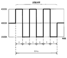
- FIG. 3 is a graph for explaining an example of the lighting test.
- the vertical axis of the graph shown in FIG. 3 indicates the color temperature of the illumination light emitted from the luminaire.
- the horizontal axis represents time, and the color temperature switching cycle s is 2 minutes.
- the test time was 12 minutes.
- the illuminance on the desk surface, which is the work surface, was set to 500 lpx.
- the state in which the luminaire emits illumination light having a color temperature of 4000 K is maintained.
- the illumination light is switched to a color temperature of 4500K, and 2 minutes after the start of the test, the illumination light is switched to 3500K.
- the switching from the color temperature of 3500K to the color temperature of 4500K and the switching from the color temperature of 4500K to the color temperature of 3500K are repeated at 2-minute intervals.
- the Kleperin test is a test that evaluates work efficiency (for example, concentration) that performs simple calculations
- the mind map test is a test that evaluates creativity.
- the number of subjects was 20. The larger the number of responses, the better the results of the Kleperin test and the mind map test.
- the illumination method for switching the color temperature between 3500K and 4500K is defined as the first illumination method.
- the second lighting method is a lighting method in which the illuminance on the desk surface is 500 lpx and the color temperature is 4000 K, which are the illuminance conditions of a general office, and the lighting is continuously lit for 12 minutes without switching the illuminance and the color temperature. do.
- the other conditions in the second lighting method are the same as those in the first lighting method.
- the third lighting method is a lighting method in which the illuminance on the desk surface is 1000 lpx and the color temperature is 4500 K, which are generally considered to improve work efficiency, and the illuminance and color temperature are continuously lit for 12 minutes without switching.
- the other conditions in the third lighting method are the same as those in the first lighting method. The inventor conducted lighting tests on these lighting methods.
- the normalized number of responses P in the formula (1) is a value obtained by normalizing the number of responses for each lighting method by the number of responses for the second lighting method in the individual.
- FIG. 4 shows the relative number of responses for each lighting method in which the values of the formula (1) were averaged by all the subjects for each lighting method.
- the normalization is performed by the number of answers of the second lighting method.
- the first lighting method gave the highest number of responses in both the Kleperin test and the mind map test. Moreover, when comparing the second lighting method and the third lighting method, the number of responses of the third lighting method was slightly higher than that of the third lighting method.
- the work efficiency is improved by alternately switching the light of two kinds of color temperatures (for example, 3500K and 4500K) at a time interval longer than 1 minute (preferably 2 minutes or more).
- two kinds of color temperatures for example, 3500K and 4500K
- the medium color temperature about 4000K, which is the average of 3500K and 4500K in this example
- the relaxing effect of light less than 4000K and the awakening effect of light of more than 4000K can be alternately provided.
- the tension for example, concentration
- the above amplitude can be regarded as a color temperature difference between the light having a first color temperature of less than 4000 K and the light having a second color temperature higher than 4000 K, which are alternately emitted.
- the above test results are generally changed within the color temperature range (3300K to 5300K) of an intermediate impression, such as 3500K and 4500K, to suppress the intensity of light stimulation, and to have a relaxing effect and an arousal effect. It is also considered that we were able to bring about alternately.
- the effect was confirmed at an amplitude of 1000 K in total, but the effect can be obtained even at an amplitude of 1200 K (for example, ⁇ 600 K) in total. In addition, the effect can be obtained even with a total amplitude of 500 K (for example, ⁇ 250 K).
- the amplitude is preferably a difference that allows a person to perceive a change in color temperature.
- the medium color temperature which is the average value of the first color temperature and the second color temperature on the desk surface has been described as 4000K, but the medium color temperature may be in the range of 3700K to 4300K. That is, it is preferable that 3700K ⁇ the average value of the first color temperature and the second color temperature on the desk surface ⁇ 4300K is satisfied.
- the illumination light of the first color temperature or the illumination light of the second color temperature is lit. Is longer than the length of time for light adaptation of the eye (for example, 40 seconds to 1 minute) and within the length of time for color adaptation by the brain (for example, 10 minutes).
- the above-mentioned “lighting time” basically refers to a color temperature continuation period h (a continuation period in a narrow sense) that does not include the transition period r, but on the premise of the transition period r ⁇ switching cycle s, the above-mentioned “lighting time”
- the “lighting time” may be regarded as the switching cycle s (duration in a broad sense). In that case, the switching cycle s including the duration h and the transition period r is longer than the time length during which the light adaptation of the eye occurs (for example, 40 seconds to 1 minute) and the time length during which the brain performs chromatic adaptation (for example). It may be within 10 minutes).
- the duration h, the transition period r, and the switching cycle s may be different between the first color temperature and the second color temperature.
- the illumination method according to the first embodiment is directly directed to the eye. Instead of encouraging awakening by giving a stimulus, it is possible to work efficiently under lighting. Therefore, in the lighting method according to the first embodiment, it is preferable to consider the illuminance and the color temperature of the desk surface.
- the transition period r when switching between the light having the first color temperature and the light having the second color temperature can be set to 1 second or less.
- a light stimulus is given to the eyes, it becomes possible to recognize the change in the color temperature, and the effect of the change in the color temperature can be obtained.
- the light stimulus perceptible to the eye can be given by changing the color temperature from the color temperature in which the eye is acclimatized.
- a sudden change in color temperature has a strong light stimulus, and some people feel a sense of discomfort. Therefore, it is preferable that the light stimulus is not too strong.
- the transition period r is a time length that is comfortable and perceptible to a person.
- the sense of incongruity indicates that the light stimulus is strongly felt due to a sudden change in color temperature.
- the transition period r (more than Specifically, the inventor confirmed that if the second transition period r2) is 10 seconds or less, a person can perceive the change in color temperature without discomfort. Therefore, the second transition period r2, which is the transition period at the time of rising change, may be 10 seconds or less or 5 seconds or less. In particular, when the second transition period r2 is 5 seconds, the operator can perceive the change in color temperature and the light stimulus is not too strong, which is preferable.
- the transition period r (more specifically, the first The inventor confirmed that if the transition period r1) of is 15 seconds or less, a person can perceive the change in color temperature without discomfort. Therefore, the first transition period r1, which is the transition period at the time of falling change, may be 15 seconds or less, 10 seconds or less, or 5 seconds or less.
- the transition period r1 at the time of falling change in which the intensity of the light stimulus is dominant, may be combined with the transition period r2 at the time of rising change.
- the transition period r is not limited to the above example, and may be any length of 15 seconds or less (for example, constant for 13 seconds, constant for 5 seconds, etc.) without distinguishing between a rising change and a falling change.
- the transition period r2 is 5 seconds
- the transition period r1 is 10 seconds, so that the transition period r1> the transition period r2.
- the lower limit values of the transition periods r, r1 and r2 are not particularly limited, but may be the shortest length that the lighting device 100 can switch.
- transition periods r, r1 and r2 assume that the color temperature change range is 1000K. Therefore, when the change range is different from 1000K, the above value may be converted into the amount of change in the color temperature per unit time and adopted. For example, when the color temperature change range of 1000 K is changed in 10 seconds, the change amount (change rate) of the color temperature per second is 100 K / sec, so that the change amount of 100 K / sec is also in other color temperature change ranges.
- the transition periods r, r1 and r2 may be set so as to change with.
- the color of the desk surface is preferably white.
- the reflectance of light on the long wavelength side is higher than that on the short wavelength side, so that the medium color temperature (amplitude) is the average value of the first color temperature and the second color temperature.
- the inventors measured the heart rate variability of each subject during the test work and analyzed the electrocardiogram. As a result of the inventors calculating LF (Low Frequency) / HF (Hi Frequency) as a stress index, the first lighting method ⁇ second lighting method ⁇ third lighting method, and the first lighting method It was confirmed that the stress during work was the lowest. As a result, the stress reduction effect during work by the first lighting method could be confirmed.
- LF Low Frequency
- HF Hi Frequency
- the third lighting method is more stressful for humans, and the third lighting method is counterproductive to the stress during work.
- rice field it is considered that a person can work more relaxedly with an illuminance of 500 lpx than with an illuminance of 1000 lpx. From this, the illuminance is preferably lower than 1000 lpx. Further, in consideration of workability, the illuminance of the work surface (here, the desk surface) is preferably 300 lpx or more so that the work can be performed without any problem and the work is not felt too dark.
- the inventors performed electroencephalogram analysis.
- the stress value as compared with the second lighting method and the third lighting method in which the illuminance and the color temperature are fixed, in the first lighting method in which the color temperature is changed, the work for the stress value before the work is performed. It was confirmed that the stress value after work showed a lower value as the amount of change in the stress value after work. This is because the first lighting method in which the color temperature is changed has a higher effect of reducing the stress value before and after the work than the second lighting method and the third lighting method in which the illuminance and the color temperature are fixed. Is shown.
- the first lighting method in which the color temperature is changed is in a concentrated state as compared with the second lighting method and the third lighting method in which the illuminance and the color temperature are fixed. It was confirmed that the work results of the work required for the work were improved and the effect of reducing the stress during the work and the stress before and after the work was high. Therefore, similarly to the first lighting method, the lighting method according to the first embodiment in which the color temperature is changed has the same effect.
- the advantage of two different color temperature lights such as maintaining the concentrated state while relaxing and maintaining the concentrated state without increasing the stress too much, is utilized.
- work efficiency can be improved.
- the work efficiency includes not only the efficiency of simple work but also the efficiency of work (including work) that requires creativity.
- FIG. 6 shows another example of the lighting test conducted by the inventors with reference to the result of the subjective evaluation.
- FIG. 6 is a graph for explaining an example of the lighting test.
- the vertical axis of the graph shown in FIG. 6 indicates the color temperature of the illumination light emitted from the luminaire.
- the horizontal axis represents time, and the color temperature switching cycle s is 2 minutes.
- the test time was 12 minutes.
- the switching cycle s (s1, s2 in the figure) during the test includes the above-mentioned transition period r (r1, r2 in the figure).
- the switching cycle s1 includes the transition period r1, and the switching cycle s2 includes the transition period r2.
- the transition period, duration, and switching cycle during a series of switching controls such as the values of the transition period r or duration h differing between (and switching control except immediately before the end of the test) and other color temperature changes. Do not necessarily have to be the same.
- the Kleperin test is a test that evaluates work efficiency (for example, concentration) that performs simple calculations
- the mind map test is a test that evaluates creativity
- the typing test is a test for simple desk work using a PC in the office. This is a test to evaluate work efficiency.
- the number of subjects was 17. The larger the number of responses, the better the results of the Kleperin test and the mind map test. In the typing test, the faster the typing speed (number of characters / second), the better the result.
- the illumination method for switching the color temperature between 3500K and 4500K is defined as the fourth illumination method.
- the sixth lighting method sets the transition period longer than that of the fifth lighting method, and makes it difficult to notice the switching of the color temperature.
- the other conditions in the fifth lighting method and the sixth lighting method are the same as those in the first lighting method.
- the normalized number of responses Q in the formula (2) is a value obtained by normalizing the number of responses for each lighting method by the number of responses for the fourth lighting method in an individual.
- FIG. 7 shows the relative number of responses for each lighting method in which the values of the formula (2) were averaged for all the subjects for each lighting method.
- normalization is performed by the number of responses of the fourth lighting method.
- the first lighting method in FIG. 4 and the fourth lighting method in FIG. 7 have the same lighting method.
- Fig. 7 in the Kleperin test, the result with the largest number of responses for the fifth lighting method was obtained.
- the mind map test the number of responses for the fifth lighting method and the sixth lighting method was large.
- the number of responses to the Kleperin test and the mind map test was larger for both the fifth lighting method and the sixth lighting method. It can be confirmed that the work results of the work requiring concentration and the work requiring creativity are improved by intentionally setting the transition period.
- the normalized number of responses R in the formula (3) is a value obtained by normalizing the speed of each lighting method by the number of responses of the fourth lighting method in the individual.
- FIG. 7 shows the relative speed of each lighting method in which the values of the formula (3) are averaged by all the subjects for each lighting method.
- normalization is performed at the speed of the fourth lighting method.
- the first lighting method in FIG. 4 and the fourth lighting method in FIG. 7 have the same lighting method.
- the typing test showed that both the fifth and sixth lighting methods were faster than the fourth lighting method.
- the sixth lighting method albeit slightly, resulted in the fastest speed.
- the color temperature is changed at a speed at which a person can perceive the change in color temperature without discomfort, as in the fifth lighting method. Therefore, the color temperature is changed rapidly as in the fourth lighting method, or as in the sixth lighting method, the light stimulus accompanying the change in the color temperature becomes weaker. It can be confirmed that the work efficiency is improved as compared with the method of changing. Therefore, for work that requires concentration, it is preferable to provide a transition period as described above.
- a method of changing the color temperature at a gentle speed at which the stimulus is weakened is more preferable.
- the inventors performed electroencephalogram analysis. As a result, it was confirmed that the average value of the stress values during the work was lower in the order of the fifth lighting method, the sixth lighting method, and the fourth lighting method. Expressed by an inequality sign, the working stress average value of the fifth lighting method ⁇ working stress average value of the sixth lighting method ⁇ working stress average value of the fourth lighting method. From the above, it can be confirmed that the fifth lighting method has the best stress suppressing effect.
- the fifth lighting method in which the transition period r is set to a speed at which the change itself can be perceived without discomfort is compared with the fourth lighting method in which the color temperature is sharply switched. It was confirmed that the work results of the work requiring a concentrated state were improved and the stress reduction effect was high. From this, it can be said that the fifth lighting method can maintain the concentrated state while further suppressing stress without feeling a sense of discomfort when switching the color temperature, as compared with the fourth lighting method. Therefore, it can be said that the fifth lighting method is more preferable, especially when it is desired to maintain the concentrated state.
- the sixth lighting method in which the color temperature is gradually switched improves the work result of simple desk work using a PC as compared with the fourth lighting method in which the color temperature is switched sharply. It was also confirmed that the stress reduction effect was high. From this, it can be said that the sixth lighting method can improve the work performance while further suppressing stress without feeling a sense of discomfort when switching the color temperature, as compared with the fourth lighting method. Therefore, it can be said that the sixth lighting method is more preferable, especially when improvement in work results is desired. Since the difference between the fifth lighting method and the sixth lighting method in the mind map test and typing test is not so large, we would like to suppress stress and continuously improve work efficiency (number of responses) for a relatively long time. In some cases, it can be said that the fifth lighting method is more preferable.
- the advantage of two different color temperature lights such as maintaining the concentrated state while relaxing and maintaining the concentrated state without increasing the stress too much, is utilized.
- the transition period by further adjusting the transition period, it is possible to further improve work efficiency and maintain a more concentrated state.
- the work efficiency includes not only the efficiency of simple work but also the efficiency of work requiring creativity (including work) or the efficiency of simple desk work using a PC.
- the lighting method may be switched depending on the work content.
- two types of control patterns a fifth lighting method and a sixth lighting method, may be switched according to the work content.
- the fifth lighting method was used, and tasks that required creativity, such as the mind map test and typing test, or a PC was used.
- the sixth lighting method may be used.
- an individual may be able to select control with a remote controller or the like according to the work. In this case, an individual may be able to select and set a setting value indicating a different transition period in one control unit.
- the lighting device 100 performs switching control by one of two or more control methods in which different transition periods are set, such as the fifth lighting method and the sixth lighting method.
- Two or more control units for example, a first control unit and a second control unit
- which control unit performs switching control can be selected by external input, for example, by inputting a set value. It may be configured in. In this case, it suffices that the two or more control units are set with set values indicating different transition periods.
- the transition period is set to 5 seconds, but the transition period may be any time length of 0.1 seconds or more and 10 seconds or less as long as the person can perceive the change in color temperature without discomfort. good.
- the upper limit of the transition period of the fifth lighting method can be set to 15 seconds or less.
- the transition period may be different for rising and falling.
- the sixth lighting method may have a longer transition period than the fifth lighting method, and may be, for example, 5 seconds or more, 10 seconds or more, or 15 seconds or more.
- the transition period is preferably not more than or equal to the length of time (for example, 1 minute or less) at which light adaptation of the eye occurs.
- the transition period (r2) is longer than 10 seconds.
- the transition period (r1) should be longer than 15 seconds.
- the transition period may be different for rising and falling. Even in that case, it is preferable that each transition period of the sixth lighting method is set to be longer than each transition period of the fifth lighting method.
- the results are better than the fourth lighting method in all three tasks in which the lighting test is performed, and the average stress value during the task is the lowest. It is preferable to use the lighting method of.
- the lighting device 100 has a first light emitting unit 110 that emits light having a first color temperature and a second light emitting unit 120 that emits light having a second color temperature.
- the first embodiment is not limited to such an example.
- the first embodiment is configured as a lighting system 101 including a first lighting device 100 # 1, a second lighting device 100 # 2, and a control device 140. You may be.
- the first lighting device 100 # 1 includes a first light emitting unit 110 # and a first communication unit 113.
- the first light emitting unit 110 # includes a first lighting unit 111 # and a first light source 112.
- the first light source 112 is the same as the first light source 112 of the lighting device 100 shown in FIG.
- the first lighting unit 111 # controls the first light source 112 to emit light having a first color temperature from the first light source 112 with an output instructed by the control device 140.
- the first communication unit 113 is a communication interface that communicates with the control device 140. For example, the first communication unit 113 gives a control signal from the control device 140 to the first lighting unit 111 #.
- the second lighting device 100 # 2 includes a second light emitting unit 120 # and a second communication unit 123.
- the second light emitting unit 120 # includes a second lighting unit 121 # and a second light source 122.
- the second light source 122 is the same as the second light source 122 of the lighting device 100 shown in FIG.
- the second lighting unit 121 # controls the second light source 122 to emit light having a second color temperature from the second light source 122 at the output instructed by the control device 140.
- the second communication unit 123 is a communication interface that communicates with the control device 140. For example, the second communication unit 123 gives a control signal from the control device 140 to the second lighting unit 121 #.
- the control device 140 includes a control unit 141 and a communication unit 142.
- the control unit 141 determines the output by the first light emitting unit 110 # and the second light emitting unit 120 #. As a result, the control unit 141 switches the color temperature of the illumination light emitted from the illumination system 101 between the first color temperature and the second color temperature.
- the control unit 141 can individually control the first lighting device 100 # 1 and the second lighting device 100 # 2.
- the communication unit 142 is a communication interface that communicates with the first lighting device 100 # 1 and the second lighting device 100 # 2. For example, the communication unit 142 gives a control signal indicating a determination by the control unit 141 to the first lighting device 100 # 1 and the second lighting device 100 # 2.
- the control device 140 described above may be a remote controller or a PC (Personal Computer). Therefore, a part or all of the control unit 141 can also be configured by the processing circuit 10, for example, as shown in FIG. 2 (A). Further, a part or all of the control unit 141 may be composed of, for example, a memory 11 and a processor 12, as shown in FIG. 2 (B).
- the lighting device 100 is installed on the ceiling of the office space and uniformly illuminates the desk surface. It should be noted that some uneven illuminance and uneven color may be present on the upper surface of the desk. There is no problem as long as the unevenness is not perceived by the human eye.
- the illuminance around the desk surface may be 20% lower than the illuminance at the center of the desk surface. In that case, it is preferable that the illuminance changes smoothly from the center of the desk surface to the periphery.
- a lighting system may be configured by providing a plurality of lighting devices 100.
- a plurality of lighting devices 100 may be installed in one room. Thereby, it becomes possible to adjust the illuminance and the color temperature on the desk surface of each area or each user.
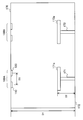
- FIG. 9 is a schematic view showing a first example of installing the lighting device 100.
- the lighting device 100A and the lighting device 100B are installed on the ceiling 170.
- Each of the lighting device 100A and the lighting device 100B has the same configuration as the lighting device 100 shown in FIG.
- the lighting device 100A will be used for description.
- the color temperature emitted is different between the first light emitting unit 110 and the second light emitting unit 120.
- the light distribution here is equivalent to Lumbershan. From the first light emitting unit 110, light of 3000 K, which is light having a first color temperature emitted from the first light source 112, is emitted. From the second light emitting unit 120, light of 5000 K, which is light having a second color temperature emitted from the second light source 122, is emitted.
- the height D2 of the desk 171 is 760 mm
- the height D1 from the floor surface 172 to the ceiling 170 is 2800 mm
- the first light source 112 of the first light emitting unit 110 is set to 500 mm.
- the interval D3 is the distance between the center of the light emitting surface of the first light source 112 of the first light emitting unit 110 and the center of the light emitting surface of the second light source 122 of the second light emitting unit 120. Is.
- the illuminance distribution and the color temperature distribution on the desk upper surface 171a of the desk 171 are substantially uniform, and there is no sense of discomfort.
- the illuminating device 100A having two first light emitting units 110 and a second light emitting unit 120 that emit light having different color temperatures, it is possible to control the color temperature to be changed.
- the interval D3 becomes larger than 500 mm, the uniformity of the color temperature distribution on the desk surface 171a decreases. Therefore, the interval D3 is preferably 500 mm or less. However, the interval D3 is larger than 0 mm.
- the first light source 112 is 3500 K and the color temperature of the light emitted from the second light source 122 is 4500 K
- the interval D3 is 600 mm or less
- the desk surface The uniformity of the color temperature distribution of 171a can be ensured.
- the difference in color temperature between the first light source 112 and the second light source 122 is 2000 K
- the first light source 112 and the second light source 122 are subjected to the condition of the interval D3 ⁇ 500 mm.
- the difference in color temperature is 1000K, it is preferable to determine the arrangement of the first light emitting unit 110 and the second light emitting unit 120 under the condition of the interval D3 ⁇ 600 mm.
- the lighting device 100 when the lighting device 100 emits light from the ceiling, it is preferable to have a narrow light distribution because it does not affect other users.
- the light distribution is narrow so that the light emitted from the lighting device 100A does not reach the desk upper surface 173b of the desk 173 of another user.
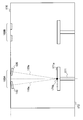
- FIG. 10 is a schematic view showing a second example in which the lighting device 100 is installed.
- the lighting device 100A and the lighting device 100B are installed on the ceiling 170.
- Each of the lighting device 100A and the lighting device 100B has the same configuration as the lighting device 100 shown in FIG.
- the lighting device 100A will be used for description.
- the central axis 110a of the light emitted from the first light emitting unit 110 and the central axis 120a of the light emitted from the second light emitting unit 120 are the centers of the desk surface 171a.
- the first light emitting unit 110 and the second light emitting unit 120 may be tilted so as to intersect at 171b. This improves the uniformity of the color temperature distribution on the desk 171.
- each of the first light emitting unit 110 # 3 and the second light emitting unit 120 # 2 has a first lighting unit 111 and a first light source.
- a set of 112 and a pair of a set of second lighting units 121 and a second light source 122 may be included.
- the first light source 112 and the second light source 122 are arranged alternately. It is preferable that it is.
- the distance between adjacent light sources is preferably 500 mm or less.
- FIG. 12 is a block diagram schematically showing the configuration of the lighting device 200 according to the second embodiment.
- the lighting device 200 includes a first light emitting unit 110, a second light emitting unit 120, a control unit 130, a first deflection unit 250, and a second deflection unit 260.
- the first light emitting unit 110, the second light emitting unit 120, and the control unit 130 of the lighting device 200 according to the second embodiment are the first light emitting unit 110 and the second light emitting unit 110 of the lighting device 100 according to the first embodiment. This is the same as the unit 120 and the control unit 130.
- the first deflection unit 250 is an optical element that deflects the traveling direction of the light emitted from the first light source 112.
- the second deflection unit 260 is an optical element that deflects the traveling direction of the light emitted from the second light source 122.
- the first deflection unit 250 and the second deflection unit 260 will be described in detail.
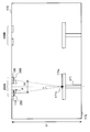
- FIG. 13 is a schematic view showing an example of installing the lighting device 200.
- the lighting device 200A and the lighting device 200B are installed on the ceiling 170.
- Each of the lighting device 200A and the lighting device 200B has the same configuration as the lighting device 200 shown in FIG. Here, the lighting device 200A will be used for description.
- the central axis 110a of the light emitted from the first light emitting unit 110 and the central axis 120a of the light emitted from the second light emitting unit 120 are formed.
- the shape may be designed so as to intersect at the center 171b of the desk upper surface 171a.
- FIG. 14 is a schematic view showing the shape of the optical element 280 used as the first deflection unit 250.
- the angle between the central axis 110b of the light output from the first deflection unit 250 and the vertical line 280b is defined as the angle ⁇ + ⁇ .
- the angle ⁇ is obtained by the following equation (4) when the interval D3 is 500 mm.
- Angle ⁇ atan (250mm / (D1-D2)) ⁇ 7 degrees (4)
- the embodiments 1 and 2 show an example in which the lighting devices 100 and 200 are installed on the ceiling 170, the embodiments 1 and 2 are not limited to such an example.
- the lighting devices 100 and 200 may be used as task lighting that can be installed on the work surface.
- the lighting devices 100 and 200 can be carried when each user concentrates on work at a desired place without being limited to the office space, so that the selectivity of the area for enhancing the concentration is enhanced.
Landscapes
- Circuit Arrangement For Electric Light Sources In General (AREA)
Priority Applications (5)
| Application Number | Priority Date | Filing Date | Title |
|---|---|---|---|
| PCT/JP2020/011147 WO2021181664A1 (ja) | 2020-03-13 | 2020-03-13 | 照明装置、照明システム及び照明方法 |
| JP2020542473A JPWO2021181664A1 (https=) | 2020-03-13 | 2020-03-13 | |
| PCT/JP2021/008208 WO2021182244A1 (ja) | 2020-03-13 | 2021-03-03 | 照明装置、照明システム及び照明方法 |
| JP2022505975A JP7474018B2 (ja) | 2020-03-13 | 2021-03-03 | 照明装置及び照明システム |
| JP2024062808A JP2024074962A (ja) | 2020-03-13 | 2024-04-09 | 照明装置及び照明システム |
Applications Claiming Priority (1)
| Application Number | Priority Date | Filing Date | Title |
|---|---|---|---|
| PCT/JP2020/011147 WO2021181664A1 (ja) | 2020-03-13 | 2020-03-13 | 照明装置、照明システム及び照明方法 |
Publications (1)
| Publication Number | Publication Date |
|---|---|
| WO2021181664A1 true WO2021181664A1 (ja) | 2021-09-16 |
Family
ID=77671636
Family Applications (2)
| Application Number | Title | Priority Date | Filing Date |
|---|---|---|---|
| PCT/JP2020/011147 Ceased WO2021181664A1 (ja) | 2020-03-13 | 2020-03-13 | 照明装置、照明システム及び照明方法 |
| PCT/JP2021/008208 Ceased WO2021182244A1 (ja) | 2020-03-13 | 2021-03-03 | 照明装置、照明システム及び照明方法 |
Family Applications After (1)
| Application Number | Title | Priority Date | Filing Date |
|---|---|---|---|
| PCT/JP2021/008208 Ceased WO2021182244A1 (ja) | 2020-03-13 | 2021-03-03 | 照明装置、照明システム及び照明方法 |
Country Status (2)
| Country | Link |
|---|---|
| JP (3) | JPWO2021181664A1 (https=) |
| WO (2) | WO2021181664A1 (https=) |
Families Citing this family (1)
| Publication number | Priority date | Publication date | Assignee | Title |
|---|---|---|---|---|
| CN117528860A (zh) * | 2023-09-19 | 2024-02-06 | 四川世纪和光科技发展有限公司 | 一种仿生脑电波发光装置 |
Citations (3)
| Publication number | Priority date | Publication date | Assignee | Title |
|---|---|---|---|---|
| JPH11135273A (ja) * | 1997-10-28 | 1999-05-21 | Matsushita Electric Works Ltd | 色温度制御照明装置とこれを用いた入眠装置、覚醒装置及び入眠覚醒装置 |
| JP2014229534A (ja) * | 2013-05-24 | 2014-12-08 | コニカミノルタ株式会社 | 照明装置 |
| JP2017004657A (ja) * | 2015-06-05 | 2017-01-05 | パナソニック株式会社 | 照明装置及びディスプレイ装置 |
Family Cites Families (5)
| Publication number | Priority date | Publication date | Assignee | Title |
|---|---|---|---|---|
| JP2010527680A (ja) | 2007-05-25 | 2010-08-19 | コーニンクレッカ フィリップス エレクトロニクス エヌ ヴィ | 照明システム |
| JP4991403B2 (ja) * | 2007-06-12 | 2012-08-01 | コイズミファニテック株式会社 | 照明器具 |
| JP5668053B2 (ja) * | 2009-04-16 | 2015-02-12 | コーニンクレッカ フィリップス エヌ ヴェ | 照明装置及び睡眠慣性を低減する又は覚醒状態を制御する方法 |
| JP2017021952A (ja) * | 2015-07-09 | 2017-01-26 | パナソニックIpマネジメント株式会社 | 照明制御装置、照明装置及び照明器具 |
| JP6771151B2 (ja) * | 2016-09-29 | 2020-10-21 | パナソニックIpマネジメント株式会社 | 環境制御システム、環境制御方法及びプログラム |
-
2020
- 2020-03-13 WO PCT/JP2020/011147 patent/WO2021181664A1/ja not_active Ceased
- 2020-03-13 JP JP2020542473A patent/JPWO2021181664A1/ja active Pending
-
2021
- 2021-03-03 JP JP2022505975A patent/JP7474018B2/ja active Active
- 2021-03-03 WO PCT/JP2021/008208 patent/WO2021182244A1/ja not_active Ceased
-
2024
- 2024-04-09 JP JP2024062808A patent/JP2024074962A/ja active Pending
Patent Citations (3)
| Publication number | Priority date | Publication date | Assignee | Title |
|---|---|---|---|---|
| JPH11135273A (ja) * | 1997-10-28 | 1999-05-21 | Matsushita Electric Works Ltd | 色温度制御照明装置とこれを用いた入眠装置、覚醒装置及び入眠覚醒装置 |
| JP2014229534A (ja) * | 2013-05-24 | 2014-12-08 | コニカミノルタ株式会社 | 照明装置 |
| JP2017004657A (ja) * | 2015-06-05 | 2017-01-05 | パナソニック株式会社 | 照明装置及びディスプレイ装置 |
Also Published As
| Publication number | Publication date |
|---|---|
| JPWO2021181664A1 (https=) | 2021-09-16 |
| JP2024074962A (ja) | 2024-05-31 |
| JP7474018B2 (ja) | 2024-04-24 |
| JPWO2021182244A1 (https=) | 2021-09-16 |
| WO2021182244A1 (ja) | 2021-09-16 |
Similar Documents
| Publication | Publication Date | Title |
|---|---|---|
| EP1345656B1 (en) | Apparatus for alleviation of symptoms by application of tinted light | |
| US5047006A (en) | Personal integrating sphere system | |
| EP2949184B1 (en) | Lighting device and lighting system | |
| US9205277B2 (en) | Color adaptive therapeutic light control system | |
| JP6580378B2 (ja) | 照明装置及びディスプレイ装置 | |
| JP5097925B2 (ja) | 人間の眼の分光感度特性の簡易推定方法及び簡易測定システム | |
| WO2021181664A1 (ja) | 照明装置、照明システム及び照明方法 | |
| JP2003334250A (ja) | 照明装置および照明制御装置 | |
| JP5031916B2 (ja) | 照明装置 | |
| CN108361606B (zh) | 照明装置 | |
| JP7410038B2 (ja) | ユーザの光感受性閾値を測定する着用可能両眼光電子デバイス | |
| JP2009050399A (ja) | 分光視感効率測定システムおよび分光視感効率測定方法 | |
| US20250221787A1 (en) | Systems and methods for targeted spectral illumination | |
| JP4237997B2 (ja) | 照明装置、照明制御装置および照明制御方法 | |
| KR101520377B1 (ko) | 서카디언 조도계 | |
| JP2017157482A (ja) | 照明装置 | |
| JP6012961B2 (ja) | 照明装置およびコントローラ | |
| JP2022095790A (ja) | 照明装置、照明システム、制御装置、及び制御方法 | |
| JP2019200915A (ja) | 照明システム及び照明方法 | |
| Vartanian et al. | Led lights with hidden intensity-modulated blue channels aiming for enhanced subconscious visual responses | |
| Wilkins et al. | Management of visual stress | |
| JP2021027016A (ja) | 照明制御システム | |
| CN107666748B (zh) | 一种动态照明方法 | |
| WO2026041556A1 (en) | System and method for generating comfortable light | |
| JP2024544837A (ja) | 照明装置 |
Legal Events
| Date | Code | Title | Description |
|---|---|---|---|
| ENP | Entry into the national phase |
Ref document number: 2020542473 Country of ref document: JP Kind code of ref document: A |
|
| 121 | Ep: the epo has been informed by wipo that ep was designated in this application |
Ref document number: 20924590 Country of ref document: EP Kind code of ref document: A1 |
|
| NENP | Non-entry into the national phase |
Ref country code: DE |
|
| 122 | Ep: pct application non-entry in european phase |
Ref document number: 20924590 Country of ref document: EP Kind code of ref document: A1 |