WO2021181664A1 - 照明装置、照明システム及び照明方法 - Google Patents
照明装置、照明システム及び照明方法 Download PDFInfo
- Publication number
- WO2021181664A1 WO2021181664A1 PCT/JP2020/011147 JP2020011147W WO2021181664A1 WO 2021181664 A1 WO2021181664 A1 WO 2021181664A1 JP 2020011147 W JP2020011147 W JP 2020011147W WO 2021181664 A1 WO2021181664 A1 WO 2021181664A1
- Authority
- WO
- WIPO (PCT)
- Prior art keywords
- color temperature
- light
- lighting
- light source
- lighting device
- Prior art date
Links
Images


Classifications
-
- H—ELECTRICITY
- H05—ELECTRIC TECHNIQUES NOT OTHERWISE PROVIDED FOR
- H05B—ELECTRIC HEATING; ELECTRIC LIGHT SOURCES NOT OTHERWISE PROVIDED FOR; CIRCUIT ARRANGEMENTS FOR ELECTRIC LIGHT SOURCES, IN GENERAL
- H05B47/00—Circuit arrangements for operating light sources in general, i.e. where the type of light source is not relevant
- H05B47/10—Controlling the light source
- H05B47/155—Coordinated control of two or more light sources
-
- H—ELECTRICITY
- H05—ELECTRIC TECHNIQUES NOT OTHERWISE PROVIDED FOR
- H05B—ELECTRIC HEATING; ELECTRIC LIGHT SOURCES NOT OTHERWISE PROVIDED FOR; CIRCUIT ARRANGEMENTS FOR ELECTRIC LIGHT SOURCES, IN GENERAL
- H05B47/00—Circuit arrangements for operating light sources in general, i.e. where the type of light source is not relevant
- H05B47/10—Controlling the light source
- H05B47/16—Controlling the light source by timing means
-
- H—ELECTRICITY
- H05—ELECTRIC TECHNIQUES NOT OTHERWISE PROVIDED FOR
- H05B—ELECTRIC HEATING; ELECTRIC LIGHT SOURCES NOT OTHERWISE PROVIDED FOR; CIRCUIT ARRANGEMENTS FOR ELECTRIC LIGHT SOURCES, IN GENERAL
- H05B47/00—Circuit arrangements for operating light sources in general, i.e. where the type of light source is not relevant
- H05B47/10—Controlling the light source
- H05B47/165—Controlling the light source following a pre-assigned programmed sequence; Logic control [LC]
-
- Y—GENERAL TAGGING OF NEW TECHNOLOGICAL DEVELOPMENTS; GENERAL TAGGING OF CROSS-SECTIONAL TECHNOLOGIES SPANNING OVER SEVERAL SECTIONS OF THE IPC; TECHNICAL SUBJECTS COVERED BY FORMER USPC CROSS-REFERENCE ART COLLECTIONS [XRACs] AND DIGESTS
- Y02—TECHNOLOGIES OR APPLICATIONS FOR MITIGATION OR ADAPTATION AGAINST CLIMATE CHANGE
- Y02B—CLIMATE CHANGE MITIGATION TECHNOLOGIES RELATED TO BUILDINGS, e.g. HOUSING, HOUSE APPLIANCES OR RELATED END-USER APPLICATIONS
- Y02B20/00—Energy efficient lighting technologies, e.g. halogen lamps or gas discharge lamps
- Y02B20/40—Control techniques providing energy savings, e.g. smart controller or presence detection
Definitions
- This disclosure relates to lighting devices, lighting systems and lighting methods.
- the impression that humans feel can be classified as follows, for example, according to the color temperature, which is the light color of lighting.
- a color temperature of less than 3300K gives a warm impression
- a color temperature of more than 5300K gives a cool impression
- a color temperature of 3300K to 5300K gives an intermediate impression. It is said that a light color with a warm impression has a relaxing effect, and a light color with a cool impression has an awakening effect.
- a lighting device that raises the arousal level or relaxes by controlling the color temperature of the lighting in office work performed in a work space such as a living room.
- a low color temperature of 3000 K or less and a medium color temperature of 4000 K are alternately generated to relax a person, and a high color temperature of 6700 K or more and a medium color temperature of 4000 K are alternately generated.
- a lighting system has been proposed that awakens people by generating color.
- the wakefulness state is a tense state or a concentrated state. Maintaining the wakefulness of a worker in office work or the like leads to the accumulation of stress and gives the worker high stress. It is known that work efficiency decreases when a high stress state continues for a long time.
- one or more aspects of the present disclosure are aimed at improving work efficiency without increasing human stress too much.
- the lighting device includes a first light source that emits light having a first color temperature of less than 4000 K, a second light source that emits light having a second color temperature higher than 4000 K, and the first light source. Switching between the light having the first color temperature and the light having the second color temperature, which are longer than 40 seconds and are alternately emitted from the first light source and the second light source at intervals of 10 minutes or less. It is characterized by including a control unit that performs control.
- the lighting system includes a first lighting device including a first light source that emits light having a first color temperature of less than 4000 K, and a second lighting system that emits light having a second color temperature higher than 4000 K.
- the second illuminating device including the two light sources, the light having the first color temperature, and the light having the second color temperature are alternately said to be longer than 40 seconds and at intervals of 10 minutes or less. It is characterized by including a first light source and a control device including a control unit that performs switching control for causing the second light source to emit light.
- light having a first color temperature of less than 4000 K and light having a second color temperature higher than 4000 K are emitted for a length of more than 40 seconds and at intervals of 10 minutes or less. It is characterized by emitting light alternately.
- FIG. (A) and (B) are block diagrams showing a hardware configuration example. It is a graph for demonstrating an example of a lighting test. It is the schematic which shows the test result of the lighting test. It is a graph for demonstrating the switching period. It is a graph for demonstrating an example of a lighting test. It is the schematic which shows the test result of the lighting test. It is a block diagram which shows schematic structure of the lighting control system which is the modification of Embodiment 1.
- FIG. It is the schematic which shows the 2nd example which installs the lighting apparatus which concerns on Embodiment 1.
- FIG. It is a block diagram which shows schematic structure of the lighting apparatus which is the modification of Embodiment 1.
- FIG. It is a block diagram which shows schematic structure of the lighting apparatus which concerns on Embodiment 2.
- FIG. It is the schematic which shows the example which installs the lighting apparatus which concerns on Embodiment 2.
- FIG. It is the schematic which shows the shape of an optical element.
- FIG. 1 is a block diagram schematically showing the configuration of the lighting device 100 according to the first embodiment.
- the lighting device 100 includes a first light emitting unit 110, a second light emitting unit 120, and a control unit 130.
- the first light emitting unit 110 emits light having a first color temperature.
- the first color temperature is a color temperature of less than 4000 K.
- the first color temperature is preferably higher than 2800K and less than 4000K, more preferably higher than 3300K and less than 4000K.
- the first light emitting unit 110 includes, for example, a first lighting unit 111 and a first light source 112.
- the first lighting unit 111 is a lighting circuit that adjusts the output of the first light source 112.
- the first lighting unit 111 emits light having a first color temperature from the first light source 112 at the output instructed by the control unit 130.
- the first light source 112 emits light having a first color temperature.
- the first light source 112 has a dimming function, and emits light having a first color temperature with an output according to control by the first lighting unit 111.
- the first light source 112 may include one or more light emitting elements. When the first light source 112 includes a plurality of light emitting elements, light having a first color temperature may be emitted as a result of synthesizing the light emitted from the plurality of light emitting elements.
- the second light emitting unit 120 emits light having a second color temperature.
- the second color temperature is a color temperature higher than 4000K.
- the second color temperature is preferably higher than 4000K and less than 5200K.
- the color temperature difference which is the difference between the first color temperature and the second color temperature, is preferably 500 K or more. Further, the color temperature difference may be 1200 K or less.
- the second light emitting unit 120 includes, for example, a second lighting unit 121 and a second light source 122.
- the second lighting unit 121 is a lighting circuit that adjusts the output of the second light source 122.
- the second lighting unit 121 emits light having a second color temperature from the second light source 122 at the output instructed by the control unit 130.
- the second light source 122 emits light having a second color temperature.
- the second light source 122 has a dimming function, and emits light having a second color temperature with an output controlled by the second lighting unit 121.
- the second light source 122 may include one or more light emitting elements. When the second light source 122 includes a plurality of light emitting elements, light having a second color temperature may be emitted as a result of synthesizing the light emitted from the plurality of light emitting elements.
- the first lighting unit 111 and the second lighting unit 121 have one common feature. It may be realized by a lighting circuit which is a lighting unit.
- a lighting circuit which is a lighting unit.
- such a lighting circuit may adjust the outputs of the first light source 112 and the second light source 122 in response to an instruction from the control unit 130.
- the lighting circuit causes the first light source 112 to emit light (lights up) or turns off at the output instructed by the control unit 130, and the second light source 122 is instructed by the control unit 130.
- the output may be emitted (lit) or turned off.
- the color temperature of the illumination light emitted from the illuminating device 100 may be switched from the first color temperature to the second color temperature or from the second color temperature to the first color temperature.
- the control unit 130 determines the output by the first light emitting unit 110 (more specifically, the first light source 112) and the second light emitting unit 120 (more specifically, the second light source 122). Then, the color temperature of the illumination light emitted from the illumination device 100 is switched between the first color temperature and the second color temperature.
- the lighting device 100 can emit light having a color temperature of, for example, 2800K to 5200K.
- the control unit 130 controls the outputs of the first light source 112 and the second light source 122 to adjust the amount of luminous flux and the color temperature emitted by each light source, thereby emitting light from the lighting device 100. Adjust the luminous flux amount and color temperature of the illumination light.
- the control by the control unit 130 includes an instruction to the first lighting unit 111 or the second lighting unit 121 described above.
- the control unit 130 also controls the lighting of the lighting device 100 over time. In other words, the control unit 130 also controls the duration of the lighting state or the extinguishing state of the lighting device 100 as a whole.
- the control unit 130 can switch the amount of light flux emitted from the lighting device 100 and the color temperature every predetermined period, for example, every two minutes.
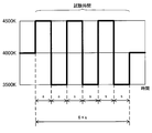
- the cycle in which the control unit 130 switches from the state in which the lighting device 100 emits light having a certain color temperature to the state in which the light having a different color temperature is emitted is set as the "color temperature switching cycle s" or simply “switching". It may be called “cycle s". More specifically, the "switching cycle s" is the next switching control, that is, the previous switching control after the switching control to the state of irradiating the light of the first color temperature or the second color temperature is performed. It is the time until the control to switch to the state of irradiating light with a color temperature different from the color temperature set as the switching destination is started. As shown in FIG.
- the illumination light emitted from the illumination device 100 is used as the first switching destination, and the first color temperature (in the example in the figure, the example in the figure).
- the second color temperature (example in the figure) as the second switching destination is started.
- the time until the switching to the light of 4500K) is started (hereinafter, also referred to as s1) and (2) the illumination light emitted from the illumination device 100 are the second switching destinations.
- the first color temperature in the example in the figure which is the first switching destination.
- the time before the start of switching to the light of 3,500 K (hereinafter, also referred to as s2) is included.
- color temperature duration h the time during which the state in which light of one color temperature is emitted in the lighting device 100 is continued.
- color temperature transition period r the time required for switching from another color temperature to the first color temperature or switching from another color temperature to the second color temperature
- s h.
- the "transition period r" is more specifically a state in which light having a first color temperature or light having a second color temperature is being irradiated to a state in which light having the other color temperature is being irradiated. The time from the start of switching to to the completion of the switching.
- the time required for switching to the first color temperature or the first color temperature, and (2) the second It may be distinguished from the color temperature or the time required for switching to the second color temperature.
- the duration of the first color temperature is the first duration h1
- the duration of the second color temperature is the second duration h2
- the transition period to the first color temperature is the first transition period.
- the transition period to r1 or the falling transition period r1 and the second color temperature may be referred to as the second transition period r2 or the rising transition period r2.
- the color temperature continuation period h and the color temperature transition period r are shown in FIG. 5, which will be described later.
- the control unit 130 adjusts the amount of light beam emitted from the first light source 112 and the second light source 122 and the color temperature via, for example, the first lighting unit 111 and the second lighting unit 121.
- the color temperature duration h, the color temperature transition period r, and the color temperature switching cycle s may be adjusted.
- control unit 130 can control the color temperature of the light emitted from the lighting device 100 by recognizing the color of the desk surface or storing it in advance. For example, if the lighting device 100 includes a color sensor (not shown), the control unit 130 can recognize the color of the desk surface. Further, the lighting device 100 can store the color of the desk surface in advance by providing a storage unit (not shown) that stores data indicating the spectral reflectance characteristic. Although the spectral reflectance characteristics are preferable, the data is data showing the relative ratio of the reflectances of R (Red: for example, 630 nm), G (Green: for example, 550 nm) and B (Blue: for example, 460 nm). There may be.
- the control unit 130 may control the color temperature of the emitted light by back-calculating from the synchrotron radiation spectral characteristics of the light reflected from the desk surface. For example, when the spectral reflectance of the desk surface is known and the color temperature calculated from the spectral reflection characteristics after reflection from the desk surface is specified, the control unit 130 may perform the control unit 130 after reflection from the desk surface. By dividing the spectral reflection characteristic by the spectral reflectance of the desk surface, the radiation spectral characteristic emitted from the illumination device 100 can be obtained, and the color temperature can be calculated back.
- the control unit 130 multiplies the radiation spectral characteristic emitted from the illuminating device 100 by the relative ratio of RGB reflectance to obtain the approximate color temperature of the emitted light. It is possible to calculate. In other words, the control unit 130 can calculate the approximate color of the desk surface using three types of relative spectral reflectances of RGB.
- the relative spectral reflectance is constant in the regions of each color of RGB, for example, in the regions of R: 600 to 700 nm, G: 500 to 600 nm, and B: 400 to 500 nm.
- the control unit 130 alternately emits light having the first color temperature and light having the second color temperature as described above for 40 minutes to 45 minutes, which is considered to be the concentration duration of a person. May be set to interrupt the switching control after performing the above. Further, when the user requests the concentration of work, for example, by giving a start instruction to the control unit 130 using an input device which is an input unit (not shown), the control unit 130 starts the switching control, and the user can start the switching control. The switching control may be continued until the end instruction is input.
- the control unit 130 may set an upper limit on the duration of the switching control. For example, the control unit 130 may end the switching control when the duration of the switching control exceeds a predetermined time (for example, 60 minutes).
- control unit 130 may perform switching control for a predetermined time (for example, a time of 40 minutes or more and 60 minutes or less).
- a predetermined time for example, a time of 40 minutes or more and 60 minutes or less.
- the lighting device 100 within the control range of the control unit 130 operates, it is preferable that the user's work area is partitioned or the lighting device 100 is installed for each user.
- the upper surface of the desk is the irradiated surface for irradiating the light of the first light source 112 and the second light source 122.
- the irradiated surface has a direction indicated by the sum of the normal vector of the light emitting surface of the first light source 112 and the normal vector of the light emitting surface of the second light source 122 as the light emitting direction. It is assumed that the horizontal plane is located at a predetermined distance (for example, 2000 mm) in the light emission direction from the midpoint between the light source 112 of 1 and the light source 122 of the second light source.
- the illuminance on the irradiated surface is preferably less than 1000 lux (lux).
- control unit 130 may be, for example, a single circuit, a composite circuit, a programmed processor, a parallel programmed processor, an ASIC, as shown in FIG. 2 (A). It can be configured by a processing circuit 10 such as an Application Specific Integrated Circuit) or an FPGA (Field Programmable Gate Array).
- a processing circuit 10 such as an Application Specific Integrated Circuit) or an FPGA (Field Programmable Gate Array).
- control unit 130 includes, for example, a memory 11 and a CPU (Central Processing Unit) for executing a program stored in the memory 11, as shown in FIG. 2 (B). It can also be configured with a processor 12.
- a program may be provided through a network, or may be recorded and provided on a recording medium. That is, such a program may be provided as, for example, a program product.
- the control unit 130 can be realized by the processing network.
- FIG. 3 is a graph for explaining an example of the lighting test.
- the vertical axis of the graph shown in FIG. 3 indicates the color temperature of the illumination light emitted from the luminaire.
- the horizontal axis represents time, and the color temperature switching cycle s is 2 minutes.
- the test time was 12 minutes.
- the illuminance on the desk surface, which is the work surface, was set to 500 lpx.
- the state in which the luminaire emits illumination light having a color temperature of 4000 K is maintained.
- the illumination light is switched to a color temperature of 4500K, and 2 minutes after the start of the test, the illumination light is switched to 3500K.
- the switching from the color temperature of 3500K to the color temperature of 4500K and the switching from the color temperature of 4500K to the color temperature of 3500K are repeated at 2-minute intervals.
- the Kleperin test is a test that evaluates work efficiency (for example, concentration) that performs simple calculations
- the mind map test is a test that evaluates creativity.
- the number of subjects was 20. The larger the number of responses, the better the results of the Kleperin test and the mind map test.
- the illumination method for switching the color temperature between 3500K and 4500K is defined as the first illumination method.
- the second lighting method is a lighting method in which the illuminance on the desk surface is 500 lpx and the color temperature is 4000 K, which are the illuminance conditions of a general office, and the lighting is continuously lit for 12 minutes without switching the illuminance and the color temperature. do.
- the other conditions in the second lighting method are the same as those in the first lighting method.
- the third lighting method is a lighting method in which the illuminance on the desk surface is 1000 lpx and the color temperature is 4500 K, which are generally considered to improve work efficiency, and the illuminance and color temperature are continuously lit for 12 minutes without switching.
- the other conditions in the third lighting method are the same as those in the first lighting method. The inventor conducted lighting tests on these lighting methods.
- the normalized number of responses P in the formula (1) is a value obtained by normalizing the number of responses for each lighting method by the number of responses for the second lighting method in the individual.
- FIG. 4 shows the relative number of responses for each lighting method in which the values of the formula (1) were averaged by all the subjects for each lighting method.
- the normalization is performed by the number of answers of the second lighting method.
- the first lighting method gave the highest number of responses in both the Kleperin test and the mind map test. Moreover, when comparing the second lighting method and the third lighting method, the number of responses of the third lighting method was slightly higher than that of the third lighting method.
- the work efficiency is improved by alternately switching the light of two kinds of color temperatures (for example, 3500K and 4500K) at a time interval longer than 1 minute (preferably 2 minutes or more).
- two kinds of color temperatures for example, 3500K and 4500K
- the medium color temperature about 4000K, which is the average of 3500K and 4500K in this example
- the relaxing effect of light less than 4000K and the awakening effect of light of more than 4000K can be alternately provided.
- the tension for example, concentration
- the above amplitude can be regarded as a color temperature difference between the light having a first color temperature of less than 4000 K and the light having a second color temperature higher than 4000 K, which are alternately emitted.
- the above test results are generally changed within the color temperature range (3300K to 5300K) of an intermediate impression, such as 3500K and 4500K, to suppress the intensity of light stimulation, and to have a relaxing effect and an arousal effect. It is also considered that we were able to bring about alternately.
- the effect was confirmed at an amplitude of 1000 K in total, but the effect can be obtained even at an amplitude of 1200 K (for example, ⁇ 600 K) in total. In addition, the effect can be obtained even with a total amplitude of 500 K (for example, ⁇ 250 K).
- the amplitude is preferably a difference that allows a person to perceive a change in color temperature.
- the medium color temperature which is the average value of the first color temperature and the second color temperature on the desk surface has been described as 4000K, but the medium color temperature may be in the range of 3700K to 4300K. That is, it is preferable that 3700K ⁇ the average value of the first color temperature and the second color temperature on the desk surface ⁇ 4300K is satisfied.
- the illumination light of the first color temperature or the illumination light of the second color temperature is lit. Is longer than the length of time for light adaptation of the eye (for example, 40 seconds to 1 minute) and within the length of time for color adaptation by the brain (for example, 10 minutes).
- the above-mentioned “lighting time” basically refers to a color temperature continuation period h (a continuation period in a narrow sense) that does not include the transition period r, but on the premise of the transition period r ⁇ switching cycle s, the above-mentioned “lighting time”
- the “lighting time” may be regarded as the switching cycle s (duration in a broad sense). In that case, the switching cycle s including the duration h and the transition period r is longer than the time length during which the light adaptation of the eye occurs (for example, 40 seconds to 1 minute) and the time length during which the brain performs chromatic adaptation (for example). It may be within 10 minutes).
- the duration h, the transition period r, and the switching cycle s may be different between the first color temperature and the second color temperature.
- the illumination method according to the first embodiment is directly directed to the eye. Instead of encouraging awakening by giving a stimulus, it is possible to work efficiently under lighting. Therefore, in the lighting method according to the first embodiment, it is preferable to consider the illuminance and the color temperature of the desk surface.
- the transition period r when switching between the light having the first color temperature and the light having the second color temperature can be set to 1 second or less.
- a light stimulus is given to the eyes, it becomes possible to recognize the change in the color temperature, and the effect of the change in the color temperature can be obtained.
- the light stimulus perceptible to the eye can be given by changing the color temperature from the color temperature in which the eye is acclimatized.
- a sudden change in color temperature has a strong light stimulus, and some people feel a sense of discomfort. Therefore, it is preferable that the light stimulus is not too strong.
- the transition period r is a time length that is comfortable and perceptible to a person.
- the sense of incongruity indicates that the light stimulus is strongly felt due to a sudden change in color temperature.
- the transition period r (more than Specifically, the inventor confirmed that if the second transition period r2) is 10 seconds or less, a person can perceive the change in color temperature without discomfort. Therefore, the second transition period r2, which is the transition period at the time of rising change, may be 10 seconds or less or 5 seconds or less. In particular, when the second transition period r2 is 5 seconds, the operator can perceive the change in color temperature and the light stimulus is not too strong, which is preferable.
- the transition period r (more specifically, the first The inventor confirmed that if the transition period r1) of is 15 seconds or less, a person can perceive the change in color temperature without discomfort. Therefore, the first transition period r1, which is the transition period at the time of falling change, may be 15 seconds or less, 10 seconds or less, or 5 seconds or less.
- the transition period r1 at the time of falling change in which the intensity of the light stimulus is dominant, may be combined with the transition period r2 at the time of rising change.
- the transition period r is not limited to the above example, and may be any length of 15 seconds or less (for example, constant for 13 seconds, constant for 5 seconds, etc.) without distinguishing between a rising change and a falling change.
- the transition period r2 is 5 seconds
- the transition period r1 is 10 seconds, so that the transition period r1> the transition period r2.
- the lower limit values of the transition periods r, r1 and r2 are not particularly limited, but may be the shortest length that the lighting device 100 can switch.
- transition periods r, r1 and r2 assume that the color temperature change range is 1000K. Therefore, when the change range is different from 1000K, the above value may be converted into the amount of change in the color temperature per unit time and adopted. For example, when the color temperature change range of 1000 K is changed in 10 seconds, the change amount (change rate) of the color temperature per second is 100 K / sec, so that the change amount of 100 K / sec is also in other color temperature change ranges.
- the transition periods r, r1 and r2 may be set so as to change with.
- the color of the desk surface is preferably white.
- the reflectance of light on the long wavelength side is higher than that on the short wavelength side, so that the medium color temperature (amplitude) is the average value of the first color temperature and the second color temperature.
- the inventors measured the heart rate variability of each subject during the test work and analyzed the electrocardiogram. As a result of the inventors calculating LF (Low Frequency) / HF (Hi Frequency) as a stress index, the first lighting method ⁇ second lighting method ⁇ third lighting method, and the first lighting method It was confirmed that the stress during work was the lowest. As a result, the stress reduction effect during work by the first lighting method could be confirmed.
- LF Low Frequency
- HF Hi Frequency
- the third lighting method is more stressful for humans, and the third lighting method is counterproductive to the stress during work.
- rice field it is considered that a person can work more relaxedly with an illuminance of 500 lpx than with an illuminance of 1000 lpx. From this, the illuminance is preferably lower than 1000 lpx. Further, in consideration of workability, the illuminance of the work surface (here, the desk surface) is preferably 300 lpx or more so that the work can be performed without any problem and the work is not felt too dark.
- the inventors performed electroencephalogram analysis.
- the stress value as compared with the second lighting method and the third lighting method in which the illuminance and the color temperature are fixed, in the first lighting method in which the color temperature is changed, the work for the stress value before the work is performed. It was confirmed that the stress value after work showed a lower value as the amount of change in the stress value after work. This is because the first lighting method in which the color temperature is changed has a higher effect of reducing the stress value before and after the work than the second lighting method and the third lighting method in which the illuminance and the color temperature are fixed. Is shown.
- the first lighting method in which the color temperature is changed is in a concentrated state as compared with the second lighting method and the third lighting method in which the illuminance and the color temperature are fixed. It was confirmed that the work results of the work required for the work were improved and the effect of reducing the stress during the work and the stress before and after the work was high. Therefore, similarly to the first lighting method, the lighting method according to the first embodiment in which the color temperature is changed has the same effect.
- the advantage of two different color temperature lights such as maintaining the concentrated state while relaxing and maintaining the concentrated state without increasing the stress too much, is utilized.
- work efficiency can be improved.
- the work efficiency includes not only the efficiency of simple work but also the efficiency of work (including work) that requires creativity.
- FIG. 6 shows another example of the lighting test conducted by the inventors with reference to the result of the subjective evaluation.
- FIG. 6 is a graph for explaining an example of the lighting test.
- the vertical axis of the graph shown in FIG. 6 indicates the color temperature of the illumination light emitted from the luminaire.
- the horizontal axis represents time, and the color temperature switching cycle s is 2 minutes.
- the test time was 12 minutes.
- the switching cycle s (s1, s2 in the figure) during the test includes the above-mentioned transition period r (r1, r2 in the figure).
- the switching cycle s1 includes the transition period r1, and the switching cycle s2 includes the transition period r2.
- the transition period, duration, and switching cycle during a series of switching controls such as the values of the transition period r or duration h differing between (and switching control except immediately before the end of the test) and other color temperature changes. Do not necessarily have to be the same.
- the Kleperin test is a test that evaluates work efficiency (for example, concentration) that performs simple calculations
- the mind map test is a test that evaluates creativity
- the typing test is a test for simple desk work using a PC in the office. This is a test to evaluate work efficiency.
- the number of subjects was 17. The larger the number of responses, the better the results of the Kleperin test and the mind map test. In the typing test, the faster the typing speed (number of characters / second), the better the result.
- the illumination method for switching the color temperature between 3500K and 4500K is defined as the fourth illumination method.
- the sixth lighting method sets the transition period longer than that of the fifth lighting method, and makes it difficult to notice the switching of the color temperature.
- the other conditions in the fifth lighting method and the sixth lighting method are the same as those in the first lighting method.
- the normalized number of responses Q in the formula (2) is a value obtained by normalizing the number of responses for each lighting method by the number of responses for the fourth lighting method in an individual.
- FIG. 7 shows the relative number of responses for each lighting method in which the values of the formula (2) were averaged for all the subjects for each lighting method.
- normalization is performed by the number of responses of the fourth lighting method.
- the first lighting method in FIG. 4 and the fourth lighting method in FIG. 7 have the same lighting method.
- Fig. 7 in the Kleperin test, the result with the largest number of responses for the fifth lighting method was obtained.
- the mind map test the number of responses for the fifth lighting method and the sixth lighting method was large.
- the number of responses to the Kleperin test and the mind map test was larger for both the fifth lighting method and the sixth lighting method. It can be confirmed that the work results of the work requiring concentration and the work requiring creativity are improved by intentionally setting the transition period.
- the normalized number of responses R in the formula (3) is a value obtained by normalizing the speed of each lighting method by the number of responses of the fourth lighting method in the individual.
- FIG. 7 shows the relative speed of each lighting method in which the values of the formula (3) are averaged by all the subjects for each lighting method.
- normalization is performed at the speed of the fourth lighting method.
- the first lighting method in FIG. 4 and the fourth lighting method in FIG. 7 have the same lighting method.
- the typing test showed that both the fifth and sixth lighting methods were faster than the fourth lighting method.
- the sixth lighting method albeit slightly, resulted in the fastest speed.
- the color temperature is changed at a speed at which a person can perceive the change in color temperature without discomfort, as in the fifth lighting method. Therefore, the color temperature is changed rapidly as in the fourth lighting method, or as in the sixth lighting method, the light stimulus accompanying the change in the color temperature becomes weaker. It can be confirmed that the work efficiency is improved as compared with the method of changing. Therefore, for work that requires concentration, it is preferable to provide a transition period as described above.
- a method of changing the color temperature at a gentle speed at which the stimulus is weakened is more preferable.
- the inventors performed electroencephalogram analysis. As a result, it was confirmed that the average value of the stress values during the work was lower in the order of the fifth lighting method, the sixth lighting method, and the fourth lighting method. Expressed by an inequality sign, the working stress average value of the fifth lighting method ⁇ working stress average value of the sixth lighting method ⁇ working stress average value of the fourth lighting method. From the above, it can be confirmed that the fifth lighting method has the best stress suppressing effect.
- the fifth lighting method in which the transition period r is set to a speed at which the change itself can be perceived without discomfort is compared with the fourth lighting method in which the color temperature is sharply switched. It was confirmed that the work results of the work requiring a concentrated state were improved and the stress reduction effect was high. From this, it can be said that the fifth lighting method can maintain the concentrated state while further suppressing stress without feeling a sense of discomfort when switching the color temperature, as compared with the fourth lighting method. Therefore, it can be said that the fifth lighting method is more preferable, especially when it is desired to maintain the concentrated state.
- the sixth lighting method in which the color temperature is gradually switched improves the work result of simple desk work using a PC as compared with the fourth lighting method in which the color temperature is switched sharply. It was also confirmed that the stress reduction effect was high. From this, it can be said that the sixth lighting method can improve the work performance while further suppressing stress without feeling a sense of discomfort when switching the color temperature, as compared with the fourth lighting method. Therefore, it can be said that the sixth lighting method is more preferable, especially when improvement in work results is desired. Since the difference between the fifth lighting method and the sixth lighting method in the mind map test and typing test is not so large, we would like to suppress stress and continuously improve work efficiency (number of responses) for a relatively long time. In some cases, it can be said that the fifth lighting method is more preferable.
- the advantage of two different color temperature lights such as maintaining the concentrated state while relaxing and maintaining the concentrated state without increasing the stress too much, is utilized.
- the transition period by further adjusting the transition period, it is possible to further improve work efficiency and maintain a more concentrated state.
- the work efficiency includes not only the efficiency of simple work but also the efficiency of work requiring creativity (including work) or the efficiency of simple desk work using a PC.
- the lighting method may be switched depending on the work content.
- two types of control patterns a fifth lighting method and a sixth lighting method, may be switched according to the work content.
- the fifth lighting method was used, and tasks that required creativity, such as the mind map test and typing test, or a PC was used.
- the sixth lighting method may be used.
- an individual may be able to select control with a remote controller or the like according to the work. In this case, an individual may be able to select and set a setting value indicating a different transition period in one control unit.
- the lighting device 100 performs switching control by one of two or more control methods in which different transition periods are set, such as the fifth lighting method and the sixth lighting method.
- Two or more control units for example, a first control unit and a second control unit
- which control unit performs switching control can be selected by external input, for example, by inputting a set value. It may be configured in. In this case, it suffices that the two or more control units are set with set values indicating different transition periods.
- the transition period is set to 5 seconds, but the transition period may be any time length of 0.1 seconds or more and 10 seconds or less as long as the person can perceive the change in color temperature without discomfort. good.
- the upper limit of the transition period of the fifth lighting method can be set to 15 seconds or less.
- the transition period may be different for rising and falling.
- the sixth lighting method may have a longer transition period than the fifth lighting method, and may be, for example, 5 seconds or more, 10 seconds or more, or 15 seconds or more.
- the transition period is preferably not more than or equal to the length of time (for example, 1 minute or less) at which light adaptation of the eye occurs.
- the transition period (r2) is longer than 10 seconds.
- the transition period (r1) should be longer than 15 seconds.
- the transition period may be different for rising and falling. Even in that case, it is preferable that each transition period of the sixth lighting method is set to be longer than each transition period of the fifth lighting method.
- the results are better than the fourth lighting method in all three tasks in which the lighting test is performed, and the average stress value during the task is the lowest. It is preferable to use the lighting method of.
- the lighting device 100 has a first light emitting unit 110 that emits light having a first color temperature and a second light emitting unit 120 that emits light having a second color temperature.
- the first embodiment is not limited to such an example.
- the first embodiment is configured as a lighting system 101 including a first lighting device 100 # 1, a second lighting device 100 # 2, and a control device 140. You may be.
- the first lighting device 100 # 1 includes a first light emitting unit 110 # and a first communication unit 113.
- the first light emitting unit 110 # includes a first lighting unit 111 # and a first light source 112.
- the first light source 112 is the same as the first light source 112 of the lighting device 100 shown in FIG.
- the first lighting unit 111 # controls the first light source 112 to emit light having a first color temperature from the first light source 112 with an output instructed by the control device 140.
- the first communication unit 113 is a communication interface that communicates with the control device 140. For example, the first communication unit 113 gives a control signal from the control device 140 to the first lighting unit 111 #.
- the second lighting device 100 # 2 includes a second light emitting unit 120 # and a second communication unit 123.
- the second light emitting unit 120 # includes a second lighting unit 121 # and a second light source 122.
- the second light source 122 is the same as the second light source 122 of the lighting device 100 shown in FIG.
- the second lighting unit 121 # controls the second light source 122 to emit light having a second color temperature from the second light source 122 at the output instructed by the control device 140.
- the second communication unit 123 is a communication interface that communicates with the control device 140. For example, the second communication unit 123 gives a control signal from the control device 140 to the second lighting unit 121 #.
- the control device 140 includes a control unit 141 and a communication unit 142.
- the control unit 141 determines the output by the first light emitting unit 110 # and the second light emitting unit 120 #. As a result, the control unit 141 switches the color temperature of the illumination light emitted from the illumination system 101 between the first color temperature and the second color temperature.
- the control unit 141 can individually control the first lighting device 100 # 1 and the second lighting device 100 # 2.
- the communication unit 142 is a communication interface that communicates with the first lighting device 100 # 1 and the second lighting device 100 # 2. For example, the communication unit 142 gives a control signal indicating a determination by the control unit 141 to the first lighting device 100 # 1 and the second lighting device 100 # 2.
- the control device 140 described above may be a remote controller or a PC (Personal Computer). Therefore, a part or all of the control unit 141 can also be configured by the processing circuit 10, for example, as shown in FIG. 2 (A). Further, a part or all of the control unit 141 may be composed of, for example, a memory 11 and a processor 12, as shown in FIG. 2 (B).
- the lighting device 100 is installed on the ceiling of the office space and uniformly illuminates the desk surface. It should be noted that some uneven illuminance and uneven color may be present on the upper surface of the desk. There is no problem as long as the unevenness is not perceived by the human eye.
- the illuminance around the desk surface may be 20% lower than the illuminance at the center of the desk surface. In that case, it is preferable that the illuminance changes smoothly from the center of the desk surface to the periphery.
- a lighting system may be configured by providing a plurality of lighting devices 100.
- a plurality of lighting devices 100 may be installed in one room. Thereby, it becomes possible to adjust the illuminance and the color temperature on the desk surface of each area or each user.
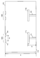
- FIG. 9 is a schematic view showing a first example of installing the lighting device 100.
- the lighting device 100A and the lighting device 100B are installed on the ceiling 170.
- Each of the lighting device 100A and the lighting device 100B has the same configuration as the lighting device 100 shown in FIG.
- the lighting device 100A will be used for description.
- the color temperature emitted is different between the first light emitting unit 110 and the second light emitting unit 120.
- the light distribution here is equivalent to Lumbershan. From the first light emitting unit 110, light of 3000 K, which is light having a first color temperature emitted from the first light source 112, is emitted. From the second light emitting unit 120, light of 5000 K, which is light having a second color temperature emitted from the second light source 122, is emitted.
- the height D2 of the desk 171 is 760 mm
- the height D1 from the floor surface 172 to the ceiling 170 is 2800 mm
- the first light source 112 of the first light emitting unit 110 is set to 500 mm.
- the interval D3 is the distance between the center of the light emitting surface of the first light source 112 of the first light emitting unit 110 and the center of the light emitting surface of the second light source 122 of the second light emitting unit 120. Is.
- the illuminance distribution and the color temperature distribution on the desk upper surface 171a of the desk 171 are substantially uniform, and there is no sense of discomfort.
- the illuminating device 100A having two first light emitting units 110 and a second light emitting unit 120 that emit light having different color temperatures, it is possible to control the color temperature to be changed.
- the interval D3 becomes larger than 500 mm, the uniformity of the color temperature distribution on the desk surface 171a decreases. Therefore, the interval D3 is preferably 500 mm or less. However, the interval D3 is larger than 0 mm.
- the first light source 112 is 3500 K and the color temperature of the light emitted from the second light source 122 is 4500 K
- the interval D3 is 600 mm or less
- the desk surface The uniformity of the color temperature distribution of 171a can be ensured.
- the difference in color temperature between the first light source 112 and the second light source 122 is 2000 K
- the first light source 112 and the second light source 122 are subjected to the condition of the interval D3 ⁇ 500 mm.
- the difference in color temperature is 1000K, it is preferable to determine the arrangement of the first light emitting unit 110 and the second light emitting unit 120 under the condition of the interval D3 ⁇ 600 mm.
- the lighting device 100 when the lighting device 100 emits light from the ceiling, it is preferable to have a narrow light distribution because it does not affect other users.
- the light distribution is narrow so that the light emitted from the lighting device 100A does not reach the desk upper surface 173b of the desk 173 of another user.
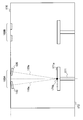
- FIG. 10 is a schematic view showing a second example in which the lighting device 100 is installed.
- the lighting device 100A and the lighting device 100B are installed on the ceiling 170.
- Each of the lighting device 100A and the lighting device 100B has the same configuration as the lighting device 100 shown in FIG.
- the lighting device 100A will be used for description.
- the central axis 110a of the light emitted from the first light emitting unit 110 and the central axis 120a of the light emitted from the second light emitting unit 120 are the centers of the desk surface 171a.
- the first light emitting unit 110 and the second light emitting unit 120 may be tilted so as to intersect at 171b. This improves the uniformity of the color temperature distribution on the desk 171.
- each of the first light emitting unit 110 # 3 and the second light emitting unit 120 # 2 has a first lighting unit 111 and a first light source.
- a set of 112 and a pair of a set of second lighting units 121 and a second light source 122 may be included.
- the first light source 112 and the second light source 122 are arranged alternately. It is preferable that it is.
- the distance between adjacent light sources is preferably 500 mm or less.
- FIG. 12 is a block diagram schematically showing the configuration of the lighting device 200 according to the second embodiment.
- the lighting device 200 includes a first light emitting unit 110, a second light emitting unit 120, a control unit 130, a first deflection unit 250, and a second deflection unit 260.
- the first light emitting unit 110, the second light emitting unit 120, and the control unit 130 of the lighting device 200 according to the second embodiment are the first light emitting unit 110 and the second light emitting unit 110 of the lighting device 100 according to the first embodiment. This is the same as the unit 120 and the control unit 130.
- the first deflection unit 250 is an optical element that deflects the traveling direction of the light emitted from the first light source 112.
- the second deflection unit 260 is an optical element that deflects the traveling direction of the light emitted from the second light source 122.
- the first deflection unit 250 and the second deflection unit 260 will be described in detail.
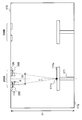
- FIG. 13 is a schematic view showing an example of installing the lighting device 200.
- the lighting device 200A and the lighting device 200B are installed on the ceiling 170.
- Each of the lighting device 200A and the lighting device 200B has the same configuration as the lighting device 200 shown in FIG. Here, the lighting device 200A will be used for description.
- the central axis 110a of the light emitted from the first light emitting unit 110 and the central axis 120a of the light emitted from the second light emitting unit 120 are formed.
- the shape may be designed so as to intersect at the center 171b of the desk upper surface 171a.
- FIG. 14 is a schematic view showing the shape of the optical element 280 used as the first deflection unit 250.
- the angle between the central axis 110b of the light output from the first deflection unit 250 and the vertical line 280b is defined as the angle ⁇ + ⁇ .
- the angle ⁇ is obtained by the following equation (4) when the interval D3 is 500 mm.
- Angle ⁇ atan (250mm / (D1-D2)) ⁇ 7 degrees (4)
- the embodiments 1 and 2 show an example in which the lighting devices 100 and 200 are installed on the ceiling 170, the embodiments 1 and 2 are not limited to such an example.
- the lighting devices 100 and 200 may be used as task lighting that can be installed on the work surface.
- the lighting devices 100 and 200 can be carried when each user concentrates on work at a desired place without being limited to the office space, so that the selectivity of the area for enhancing the concentration is enhanced.
Landscapes
- Circuit Arrangement For Electric Light Sources In General (AREA)
Abstract
4000K未満の第1の色温度の光を発する第1の光源(112)と、4000Kよりも高い第2の色温度の光を発する第2の光源(122)と、第1の色温度の光と、第2の色温度の光とを、40秒よりも長く、10分以内の間隔で、交互に、第1の光源(112)及び第2の光源(122)に発光させる切替制御を行う制御部(130)とを備える。
Description
本開示は、照明装置、照明システム及び照明方法に関する。
人間が感じる印象は、照明の光色である色温度により、例えば、次のように分類できる。3300K未満の色温度は、暖かい印象、5300Kを超える色温度は、涼しい印象、3300K~5300Kの色温度は、それらの中間の印象を与えるとされている。暖かい印象のある光色は、リラックス効果があり、涼しい印象のある光色は、覚醒効果があるといわれている。
従来より、居室等の作業空間で行う事務作業等において、照明の色温度を制御することによって、覚醒度を高める、あるいは、リラックスさせる照明装置がある。例えば、特許文献1では、3000K以下の低色温度と、4000Kの中色温度とを交互に発生させることによって、人をリラックスさせ、6700K以上の高色温度と、4000Kの中色温度とを交互に発生させることによって、人を覚醒させる照明システムが提案されている。
人が覚醒している状態では、その人は緊張し、集中する状態となる。このため、覚醒状態は、緊張状態又は集中状態であるともいえる。事務作業等において、作業員の覚醒状態を維持させることは、ストレスの蓄積につながり、その作業員に高ストレスを与えることとなる。高ストレスの状態が長く続くと、作業効率が低下することが知られている。
一方で、作業員がリラックス状態である場合、時間の長短に関わらず、覚醒状態時に比べて作業効率が低下することが知られている。
そこで、本開示の一又は複数の態様は、人のストレスを高めすぎることなく作業効率を向上させることを目的とする。
本開示の一態様に係る照明装置は、4000K未満の第1の色温度の光を発する第1の光源と、4000Kよりも高い第2の色温度の光を発する第2の光源と、前記第1の色温度の光と、前記第2の色温度の光とを、40秒よりも長く、10分以内の間隔で、交互に、前記第1の光源及び前記第2の光源に発光させる切替制御を行う制御部と、を備えることを特徴とする。
本開示の一態様に係る照明システムは、4000K未満の第1の色温度の光を発する第1の光源を備える第1の照明装置と、4000Kよりも高い第2の色温度の光を発する第2の光源を備える第2の照明装置と、前記第1の色温度の光と、前記第2の色温度の光とを、40秒よりも長く、10分以内の間隔で、交互に、前記第1の光源及び前記第2の光源に発光させる切替制御を行う制御部を備える制御装置と、を備えることを特徴とする。
本開示の一態様に係る照明方法は、4000K未満の第1の色温度の光と、4000Kよりも高い第2の色温度の光とを、40秒よりも長く、10分以内の間隔で、交互に発光することを特徴とする。
本開示の一又は複数の態様によれば、人のストレスを高めすぎることなく作業効率を向上させることができるようになる。
実施の形態1.
図1は、実施の形態1に係る照明装置100の構成を概略的に示すブロック図である。
照明装置100は、第1の発光部110と、第2の発光部120と、制御部130とを備える。
図1は、実施の形態1に係る照明装置100の構成を概略的に示すブロック図である。
照明装置100は、第1の発光部110と、第2の発光部120と、制御部130とを備える。
第1の発光部110は、第1の色温度の光を発光する。第1の色温度は、4000K未満の色温度である。例えば、第1の色温度は、2800Kよりも高く、4000K未満の色温度であることが好ましく、3300Kよりも高く、4000K未満の色温度であることがさらに好ましい。
第1の発光部110は、例えば、第1の点灯部111と、第1の光源112とを備える。
第1の点灯部111は、第1の光源112の出力を調整する点灯回路である。例えば、第1の点灯部111は、制御部130から指示された出力で、第1の光源112から第1の色温度の光を発光させる。
第1の光源112は、第1の色温度の光を出射する。第1の光源112は、調光機能を有し、第1の点灯部111による制御に応じた出力で、第1の色温度の光を出射する。第1の光源112は、1つ又は複数の発光素子を含むことができる。第1の光源112が複数の発光素子を含む場合、それら複数の発光素子から出射される光の合成の結果、第1の色温度の光が出射されてもよい。
第1の点灯部111は、第1の光源112の出力を調整する点灯回路である。例えば、第1の点灯部111は、制御部130から指示された出力で、第1の光源112から第1の色温度の光を発光させる。
第1の光源112は、第1の色温度の光を出射する。第1の光源112は、調光機能を有し、第1の点灯部111による制御に応じた出力で、第1の色温度の光を出射する。第1の光源112は、1つ又は複数の発光素子を含むことができる。第1の光源112が複数の発光素子を含む場合、それら複数の発光素子から出射される光の合成の結果、第1の色温度の光が出射されてもよい。
第2の発光部120は、第2の色温度の光を発光する。第2の色温度は、4000Kよりも高い色温度である。例えば、第2の色温度は、4000Kよりも高く、5200K未満の色温度であることが好ましい。
また、第1の色温度と、第2の色温度との差である色温度差は、500K以上が好ましい。また、その色温度差は、1200K以下であってもよい。
また、第1の色温度と、第2の色温度との差である色温度差は、500K以上が好ましい。また、その色温度差は、1200K以下であってもよい。
第2の発光部120は、例えば、第2の点灯部121と、第2の光源122とを備える。
第2の点灯部121は、第2の光源122の出力を調整する点灯回路である。例えば、第2の点灯部121は、制御部130から指示された出力で、第2の光源122から第2の色温度の光を発光させる。
第2の光源122は、第2の色温度の光を出射する。第2の光源122は、調光機能を有し、第2の点灯部121による制御に応じた出力で、第2の色温度の光を出射する。なお、第2の光源122は、1つ又は複数の発光素子を含むことができる。第2の光源122が複数の発光素子を含む場合、それら複数の発光素子から出射される光の合成の結果、第2の色温度の光が出射されてもよい。
第2の点灯部121は、第2の光源122の出力を調整する点灯回路である。例えば、第2の点灯部121は、制御部130から指示された出力で、第2の光源122から第2の色温度の光を発光させる。
第2の光源122は、第2の色温度の光を出射する。第2の光源122は、調光機能を有し、第2の点灯部121による制御に応じた出力で、第2の色温度の光を出射する。なお、第2の光源122は、1つ又は複数の発光素子を含むことができる。第2の光源122が複数の発光素子を含む場合、それら複数の発光素子から出射される光の合成の結果、第2の色温度の光が出射されてもよい。
なお、図1では、第1の点灯部111と、第2の点灯部121とを分けて示しているが、第1の点灯部111と、第2の点灯部121とは、1つの共通の点灯部である点灯回路により実現されてもよい。例えば、そのような点灯回路により、制御部130からの指示に応じて第1の光源112及び第2の光源122の出力が調整されてもよい。そのような場合において、例えば、点灯回路は、第1の光源112を、制御部130から指示された出力で発光(点灯)又は消灯させるとともに、第2の光源122を、制御部130から指示された出力で発光(点灯)又は消灯させてもよい。これにより、照明装置100から出射される照明光の色温度が、第1の色温度から第2の色温度へ、又は、第2の色温度から第1の色温度へ切り替えられてもよい。
制御部130は、第1の発光部110(より具体的には、第1の光源112)及び第2の発光部120(より具体的には、第2の光源122)による出力を決定することで、照明装置100から出射される照明光の色温度を、第1の色温度から第2の色温度の間で切り替える切替制御を行う。制御部130が第1の光源112及び第2の光源122の出力を制御することで、照明装置100は、例えば、2800K~5200Kの色温度の光を出射することが可能となる。
具体的には、制御部130は、第1の光源112及び第2の光源122の出力を制御して、各光源が出射する光束量及び色温度を調整することにより、照明装置100から出射される照明光の光束量及び色温度を調整する。ここで、制御部130による制御には、上述した第1の点灯部111又は第2の点灯部121に対する指示が含まれる。
また、制御部130は、照明装置100の時間的な点灯制御も行う。言い換えると、制御部130は、照明装置100全体としての点灯状態又は消灯状態の継続時間の制御も行う。制御部130は、予め定められた期間毎、例えば、2分毎に照明装置100から出射する光束量及び色温度を切り替えることが可能である。
また、制御部130は、照明装置100の時間的な点灯制御も行う。言い換えると、制御部130は、照明装置100全体としての点灯状態又は消灯状態の継続時間の制御も行う。制御部130は、予め定められた期間毎、例えば、2分毎に照明装置100から出射する光束量及び色温度を切り替えることが可能である。
以下、制御部130が、照明装置100がある色温度の光を出射している状態から、それとは異なる色温度の光を出射する状態に切り替える周期を「色温度切替周期s」又は単に「切替周期s」という場合がある。「切替周期s」は、より具体的には、第1の色温度又は第2の色温度の光を照射する状態への切替制御を行った以後、次の切替制御、即ち前回の切替制御における切替先とされた色温度とは異なる色温度の光を照射する状態に切り替える制御を開始するまでの時間をいう。図3に示されているように、切替周期sには、(1)照明装置100から出射される照明光を、第1の切替先とされた第1の色温度(図中の例では、3500K)以外の色温度(例えば、4000K又は4500K)の光から第1の色温度の光への切り替えを開始してから、第2の切替先とされた第2の色温度(図中の例では、4500K)の光への切り替えを開始するまでの時間(以下、s1とも表記する)、及び、(2)照明装置100から出射される照明光を、第2の切替先とされた第2の色温度(図中の例では、4500K)以外の色温度の光から第2の色温度の光に切り替え始めた以後、第1の切り替え先である第1の色温度(図中の例では、3500K)の光に切替え始める前までの時間(以下、s2とも表記する)、が含まれる。なお、図3では、上記の(1)及び(2)を区別なく、s1=s2=sとして示しているが、s1≠s2であってもよい。
また、以下では、照明装置100において1つの色温度の光が出射される状態が継続される時間を「色温度継続期間h」、又は、単に「継続期間h」という場合がある。なお、図3に示すように、他の色温度から第1の色温度への切替、又は、他の色温度から第2の色温度への切替に要する時間(以下、「色温度移行期間r」、又は、単に「移行期間r」という)が無視できる程小さい場合等は、s=hと見なすことができる。ここで、「移行期間r」は、より具体的に、第1の色温度の光又は第2の色温度の光が照射されている状態から、他方の色温度の光が照射されている状態への切り替えを開始してから、その切り替えが完了するまでの時間をいう。
色温度継続期間h及び色温度移行期間rにおいても、色温度切替周期sと同様、(1)第1の色温度又は第1の色温度への切替にかかる時間と、(2)第2の色温度又は第2の色温度への切替にかかる時間とを区別してもよい。以下では、第1の色温度の継続期間を第1の継続期間h1、第2の色温度の継続期間を第2の継続期間h2、第1の色温度への移行期間を第1の移行期間r1又は立ち下がり移行期間r1、第2の色温度への移行期間を第2の移行期間r2又は立ち上がり移行期間r2という場合がある。ここで、h1≠h2であってもよいし、r1≠r2であってもよい。
なお、色温度継続期間h及び色温度移行期間rについては、後述する図5に示している。
なお、色温度継続期間h及び色温度移行期間rについては、後述する図5に示している。
制御部130は、例えば、第1の点灯部111及び第2の点灯部121を介して、第1の光源112及び第2の光源122が出射する光束量及び色温度を調整することにより、上記の色温度継続期間h、色温度移行期間r及び色温度切替周期sを調整してもよい。
また、制御部130は、机上面の色を認識し、又は、予め記憶しておくことにより、照明装置100から出射される光の色温度を制御することができる。例えば、照明装置100が図示しない色センサを備えることで、制御部130は、机上面の色を認識することができる。
また、照明装置100は、分光反射率特性を示すデータを記憶する図示しない記憶部を備えることで、机上面の色を予め記憶しておくことができる。なお、そのデータは、分光反射率特性が好ましいが、R(Red:例えば、630nm)、G(Green:例えば、550nm)及びB(Blue:例えば、460nm)の反射率の相対比を示すデータであってもよい。
また、照明装置100は、分光反射率特性を示すデータを記憶する図示しない記憶部を備えることで、机上面の色を予め記憶しておくことができる。なお、そのデータは、分光反射率特性が好ましいが、R(Red:例えば、630nm)、G(Green:例えば、550nm)及びB(Blue:例えば、460nm)の反射率の相対比を示すデータであってもよい。
机上面の分光反射率特性が用いられる場合は、分光反射率に照明装置100から出射される放射分光特性を乗じて算出した色温度が、机上面から反射した光の色温度となる。従って、制御部130は、机上面から反射した光の放射分光特性から逆算することにより、出射する光の色温度を制御してもよい。例えば、机上面の分光反射率が既知であり、かつ、机上面からの反射後の分光反射特性より算出される色温度が特定されている場合、制御部130は、机上面からの反射後の分光反射特性を、机上面の分光反射率で除することにより、照明装置100から出射する放射分光特性が求まり、色温度を逆算することが可能となる。
RGBの反射率の相対比が用いられる場合は、制御部130は、照明装置100から出射される放射分光特性にRGBの反射率の相対比を乗ずることで、出射する光のおおよその色温度を算出することが可能である。言い換えると、制御部130は、RGBの3種類の相対分光反射率を用いて机上面のおおよその色を算出することができる。RGBの各色の領域内、例えば、R:600~700nm、G:500~600nm、及び、B:400~500nmの領域内は、相対分光反射率を一定とする。
制御部130は、人の集中持続時間とされている40分~45分の間、上述したような第1の色温度の光と、第2の色温度の光とを交互に発光させる切替制御を行った後に、その切替制御を中断するように設定されていてもよい。また、ユーザが作業の集中を求める際に、例えば、図示しない入力部である入力装置を用いて、制御部130に開始指示を行うことで、制御部130は、切替制御を開始し、ユーザが終了指示を入力するまで、切替制御を継続してもよい。なお、制御部130は切替制御の継続時間に上限を設けてもよい。例えば、制御部130は、切替制御の継続時間が予め決められた時間(例えば、60分)を超えた場合に、切替制御を終了してもよい。また、例えば、制御部130は、予め定められた時間(例えば、40分以上、60分以下の時間)、切替制御を行うようにしてもよい。これにより、ユーザの負荷が高くなりすぎることを抑制でき、また、ユーザが照明状態(例えば、一般的な照明状態か、切替制御を伴う作業用の照明状態か)を選択することも可能になる。
但し、制御部130の制御範囲内の照明装置100が動作するため、ユーザの作業領域をパーティションで区切る、又は、各ユーザ用に照明装置100が設置されていることが好ましい。
なお、ここでは、机上面が、第1の光源112及び第2の光源122の光を照射する被照射面となる。被照射面は、第1の光源112における光の出射面の法線ベクトルと、第2の光源122における光の出射面の法線ベクトルとの和が示す方向を、光の出射方向とし、第1の光源112及び第2の光源122の中間点から、光の出射方向に予め定められた距離(例えば、2000mm)離れた位置の水平面であるものとする。なお、この被照射面での照度は、1000lx(ルクス)未満であることが好ましい。
なお、ここでは、机上面が、第1の光源112及び第2の光源122の光を照射する被照射面となる。被照射面は、第1の光源112における光の出射面の法線ベクトルと、第2の光源122における光の出射面の法線ベクトルとの和が示す方向を、光の出射方向とし、第1の光源112及び第2の光源122の中間点から、光の出射方向に予め定められた距離(例えば、2000mm)離れた位置の水平面であるものとする。なお、この被照射面での照度は、1000lx(ルクス)未満であることが好ましい。
以上に記載された制御部130の一部又は全部は、例えば、図2(A)に示されているように、単一回路、複合回路、プログラム化したプロセッサ、並列プログラム化したプロセッサ、ASIC(Application Specific Integrated Circuit)又はFPGA(Field Programmable Gate Array)等の処理回路10で構成することができる。
また、制御部130の一部又は全部は、例えば、図2(B)に示されているように、メモリ11と、メモリ11に格納されているプログラムを実行するCPU(Central Processing Unit)等のプロセッサ12とにより構成することもできる。このようなプログラムは、ネットワークを通じて提供されてもよく、また、記録媒体に記録されて提供されてもよい。即ち、このようなプログラムは、例えば、プログラムプロダクトとして提供されてもよい。
以上のように、制御部130は、処理回路網により実現することができる。
以上のように、制御部130は、処理回路網により実現することができる。
次に、発明者が行った照明試験の一例を説明する。
図3は、照明試験の一例を説明するためのグラフである。
図3に示されているグラフの縦軸は、照明器具から出射される照明光の色温度を示している。その横軸は、時間を示しており、色温度の切替周期sが2分である。試験時間は12分間とした。また、作業面である机上面の照度は、500lxとした。
図3は、照明試験の一例を説明するためのグラフである。
図3に示されているグラフの縦軸は、照明器具から出射される照明光の色温度を示している。その横軸は、時間を示しており、色温度の切替周期sが2分である。試験時間は12分間とした。また、作業面である机上面の照度は、500lxとした。
まず、試験開始前は、照明器具が4000Kの色温度の照明光を出射している状態を維持する。試験開始と同時に、その照明光は、4500Kの色温度に切り替えられ、試験開始から2分後に、その照明光は、3500Kに切り替えられる。その後、試験終了まで、3500Kから4500Kの色温度への切り替えと、4500Kから3500Kの色温度への切り替えとが2分間隔で繰り返される。
以上の照明試験では、クレペリン試験と、マインドマップ試験とが行われ、照明器具としては、アンビエント照明器具が用いられ、机上面は、概ね均一に照明された。クレペリン試験は、単純な計算を行う作業効率(例えば、集中力)を評価する試験であり、マインドマップ試験は、創造性を評価する試験である。被験者数は20名とした。なお、クレペリン試験及びマインドマップ試験は、回答数が多いほど、良い成績となる。
ここで、図3に示されているように、色温度を3500Kと4500Kとの間で切り替える照明方法を第1の照明方法とする。
また、一般的な執務室の照度条件となる、机上面の照度を500lx及び色温度を4000Kとして、照度及び色温度を切り替えずに12分間持続して点灯させる照明方法を第2の照明方法とする。なお、第2の照明方法における他の条件については、第1の照明方法と同様である。
また、一般的な執務室の照度条件となる、机上面の照度を500lx及び色温度を4000Kとして、照度及び色温度を切り替えずに12分間持続して点灯させる照明方法を第2の照明方法とする。なお、第2の照明方法における他の条件については、第1の照明方法と同様である。
また、一般に業務効率が向上するとされている条件となる、机上面の照度を1000lx及び色温度を4500Kとして、照度及び色温度は切り替えずに12分間持続して点灯させる照明方法を第3の照明方法とする。なお、第3の照明方法における他の条件は、第1の照明方法と同様である。発明者は、これらの照明方法において、照明試験を行った。
以上の照明試験の試験結果を、図4に示す。図4では、クレペリン試験及びマインドマップ試験の回答数を各照明方法で比較するため、まず、回答数の個人差を除去するため、各被験者の回答数を以下の式(1)で正規化した正規化回答数Pを算出する。
P=(各照明方法の回答数)/(第2の照明方法の回答数) (1)
P=(各照明方法の回答数)/(第2の照明方法の回答数) (1)
式(1)の正規化回答数Pは、個人において、第2の照明方法の回答数で各照明方法の回答数を正規化した値である。式(1)の値を照明方法毎に被験者全員で平均化した各照明方法の相対回答数を図4に示している。ここで、一般的な執務室の照度条件に対して作業効率を比較するため、第2の照明方法の回答数で正規化を行っている。
図4により、クレペリン試験及びマインドマップ試験の両方とも、第1の照明方法が最も回答数の多い結果となった。また、第2の照明方法と、第3の照明方法とを比較するとわずかではあるが、第3の照明方法の方の回答数が上回った。
これより、2種類の色温度の光(例えば、3500Kと4500K)を、1分より長い時間間隔(好ましくは2分以上)で、交互に切替えることにより、作業効率が向上すると考えられる。言い換えると、2つの光色の略中間となる中色温度(本例でいうと3500Kと4500Kとの平均である4000K程度)に対して±500K(合計1000K)の振幅で交互に発光させることにより、4000K未満の光がもたらすリラックス効果と、4000Kを超える光がもたらす覚醒効果とを交互にもたらすことができる。その結果として、リラックスしながら緊張感(例えば、集中力)を維持できたと考えられる。
ここで、上記の振幅は、交互に発光させた、4000K未満の第1の色温度の光と、4000Kより高い第2の色温度の光との色温度差とみなすことができる。
また、上記の試験結果は、3500K及び4500Kのように一般に中間の印象の色温度範囲内(3300K~5300K)で変化させることにより、光刺激の強度を抑制しながら、リラックス効果と、覚醒効果とを交互にもたらすことができたとも考えられる。
また、上記の試験結果は、3500K及び4500Kのように一般に中間の印象の色温度範囲内(3300K~5300K)で変化させることにより、光刺激の強度を抑制しながら、リラックス効果と、覚醒効果とを交互にもたらすことができたとも考えられる。
なお、上記の照明試験では、合計で1000Kの振幅で効果を確認したが、合計で1200K(例えば、±600K)の振幅でも効果が得られる。
また、合計で500K(例えば、±250K)の振幅でも効果は得られる。
なお、振幅は、人が色温度の変化を知覚できる程度の差であることが好ましい。
また、上記では机上面での第1の色温度と第2の色温度の平均値となる中色温度は4000Kとして説明したが、中色温度は、3700K~4300Kの範囲内でもよい。すなわち、3700K≦机上面での第1の色温度と第2の色温度の平均値≦4300Kが満たされるのが好ましい。
また、合計で500K(例えば、±250K)の振幅でも効果は得られる。
なお、振幅は、人が色温度の変化を知覚できる程度の差であることが好ましい。
また、上記では机上面での第1の色温度と第2の色温度の平均値となる中色温度は4000Kとして説明したが、中色温度は、3700K~4300Kの範囲内でもよい。すなわち、3700K≦机上面での第1の色温度と第2の色温度の平均値≦4300Kが満たされるのが好ましい。
ここでは机上面の色温度差(振幅)及び色温度を用いて説明したが、光源の色温度差(振幅)及び色温度と読み替えてもよい。なお、これは、以下の記載でも同様である。
以上の試験結果から、図1に示されている照明装置100により照明を行う方法である実施の形態1に係る照明方法では、第1の照明方法と同様に、第1の色温度の光と、第2の色温度の光とを交互に切り替える。
実施の形態1に係る照明方法では、第1の色温度と、第2の色温度との切替制御を行う際、第1の色温度の照明光又は第2の色温度の照明光の点灯時間を眼の明順応がおきる時間長(例えば、40秒から1分)より長く、かつ、脳が色順応を行う時間長(例えば、10分)以内とする。ここで、上記の「点灯時間」は、基本的に、移行期間rを含まない色温度継続期間h(狭義の継続期間)を指すが、移行期間r<切替周期sを前提に、上記の「点灯時間」を切替周期s(広義の継続期間)と見なしてもよい。その場合、継続期間hと移行期間rとを含む切替周期sを、眼の明順応がおきる時間長(例えば、40秒から1分)より長く、かつ、脳が色順応を行う時間長(例えば、10分)以内としてもよい。なお、上述したように、継続期間h、移行期間r及び切替周期sは、第1の色温度と第2の色温度とで異なるようにしてもよい。
第1の色温度及び第2の色温度の照明光のそれぞれの点灯時間を、眼および脳の順応速度を考慮した長さとすることにより、実施の形態1に係る照明方法は、眼に直接的な刺激を与えることにより覚醒を促すのではなく、照明下での作業を効率的に行うことができるようにしている。従って、実施の形態1に係る照明方法では、机上面の照度及び色温度を考慮することが好ましい。
第1の色温度及び第2の色温度の照明光のそれぞれの点灯時間を、眼および脳の順応速度を考慮した長さとすることにより、実施の形態1に係る照明方法は、眼に直接的な刺激を与えることにより覚醒を促すのではなく、照明下での作業を効率的に行うことができるようにしている。従って、実施の形態1に係る照明方法では、机上面の照度及び色温度を考慮することが好ましい。
このとき、例えば、第1の色温度の光と、第2の色温度の光とを切り替える際の移行期間rを、1秒以下とすることも可能である。これにより、眼へ光刺激が与えられ、色温度の変化を認識することが可能となり、色温度の変化の効果が得られる。
ここで、色温度の変化の効果を得るには、眼が順応している状態の色温度から、色温度を変化させることによって、眼が知覚可能な光刺激を与えることができればよい。しかし、急峻な色温度の変化は、光刺激が強く、人によっては違和感が感じられるため、光刺激が強すぎないことがよい。言い換えると、移行期間rは、違和感がなく、かつ、人が知覚可能な時間長であることがより好ましい。ここで、違和感とは急峻な色温度の変化により、光刺激が強く感じることを示す。
発明者が主観評価を行った結果、相対的に低色温度から高色温度(例えば、3500Kから4500K)に色温度を変化させる場合、言い換えると、立ち上がり変化の場合には、移行期間r(より具体的には、第2の移行期間r2)が10秒以下であれば、人は違和感なくその色温度の変化を知覚可能であることを、発明者は確認した。従って、立ち上がり変化時の移行期間である第2の移行期間r2は、10秒以下又は5秒以下でもよい。特に、第2の移行期間r2が5秒のとき、作業者は、色温度の変化が知覚でき、かつ光刺激が強すぎないため、好ましい。
また、相対的に高色温度から低色温度(例えば、4500Kから3500K)に色温度を変化させる場合、言い換えると、立ち下がり変化の場合には、移行期間r(より具体的には、第1の移行期間r1)は15秒以下であれば、人は違和感なくその色温度の変化を知覚可能であることを、発明者は確認した。従って、立ち下がり変化時の移行期間である第1の移行期間r1は15秒以下、10秒以下又は5秒以下でもよい。
なお、主観評価では色温度が高くなる場合(立ち上がり変化の場合)より、色温度が低くなる場合(立ち下がり変化の場合)の方が変化に対する光刺激が強いことが確認できた。これより、特に、光刺激の強度が支配的である立ち下がり変化時の移行期間r1に、立ち上がり変化時の移行期間r2を合わせてもよい。換言すると、r1=r2=15秒以下としてもよい。また、例えば、r1=r2=10秒とすれば立ち上がり変化時の移行期間r2と、立ち下がり変化時の移行期間r1との双方において、違和感なく知覚可能となるため、より好ましい。
なお、移行期間rは上記の例に限定されず、例えば立ち上がり変化と立ち下がり変化とを区別なく、15秒以下の任意の長さ(例えば、13秒一定、5秒一定など)としてもよい。あるいは、図5に示されているように、立ち上がり変化の場合は、移行期間r2を5秒、立ち下がり変化の場合は、移行期間r1を10秒のように、移行期間r1>移行期間r2となるようにしてもよい。ちなみに、移行期間r、r1、r2の下限値は、特に限定されないが、照明装置100が切り替えを行うことのできる最短の長さでよい。
なお、上記の移行期間r、r1、r2は、色温度の変化範囲が1000Kであることを想定している。従って、変化範囲が1000Kと異なる場合は、上記の値を単位時間当たりの色温度の変化量に換算して採用してもよい。例えば、1000Kの色温度変化範囲を10秒で変化させる場合、1秒当たりの色温度の変化量(変化速度)は100K/秒となるので、他の色温度変化範囲でも100K/秒の変化量で変化するように移行期間r、r1、r2を設定してもよい。
なお、机上面に反射した光が眼に入射するため、机上面の色は、白色が好ましい。例えば、茶色い木目調の場合は、短波長側の光より長波長側の光の反射率が高いため、第1の色温度と第2の色温度との平均値となる中色温度(振幅)を上述した範囲(3700K~4300K)よりも高い値にしてもよい。
また、人が白色の紙面上で作業を行い、かつ、白色の紙面の領域が視界の大半を占める場合には、紙面で光が反射し、人の眼に知覚されるため、照明装置100の出射光の色温度を調整する必要はない。
上記の照明試験において、発明者らは、試験作業中の各被験者の心拍変動を計測し、その心電図の解析を行った。発明者らが、ストレス指標となるLF(Low Frequency)/HF(Hi Frequency)を算出した結果、第1の照明方法<第2の照明方法<第3の照明方法となり、第1の照明方法が最も作業中のストレスが低いことを確認した。これにより、第1の照明方法による作業中のストレス低減効果が確認できた。
第2の照明方法及び第3の照明方法では、第3の照明方法の方が、人はストレスを感じており、第3の照明方法は、作業中のストレスには逆効果であることがわかった。言い換えると、1000lxの照度よりも、500lxの照度の方が、人は、リラックスして作業を行うことができると考えられる。これより、照度は、1000lxより低い方が好ましい。また、作業性を考慮し、作業面(ここでは、机上面)の照度は、問題なく作業が可能であり、かつ、暗すぎると感じない300lx以上が好ましい。
さらに、上記の照明試験において、発明者らは、脳波解析を行った。その結果、ストレス値に関して、照度及び色温度を固定した第2の照明方法及び第3の照明方法と比較して、色温度を変化させた第1の照明方法では、作業前のストレス値に対する作業後のストレス値の変化量として、作業後のストレス値がより低い値を示すことが確認された。これは、色温度を変化させた第1の照明方法は、照度及び色温度を固定した第2の照明方法及び第3の照明方法と比較して、作業前後におけるストレス値の低減効果が高いことを示している。
従って、心電解析及び脳波解析の結果から、色温度を変化させた第1の照明方法は、照度及び色温度を固定した第2の照明方法及び第3の照明方法と比較して、集中状態が必要とされる作業の作業成績が向上すると共に作業中のストレス及び作業前後のストレスの低減効果が高いことが確認された。
このため、第1の照明方法と同様に、色温度を変化させた実施の形態1に係る照明方法も、同様の効果を備える。
このため、第1の照明方法と同様に、色温度を変化させた実施の形態1に係る照明方法も、同様の効果を備える。
以上のように、実施の形態1によれば、リラックスしながら集中状態を維持させるとともに、ストレスを高めすぎることなく集中状態を持続させるといった、2つの異なる色温度の光が人に与える利点を活かすことで、作業効率を向上させることができる。ここで、作業効率には、単純な作業の効率だけでなく創造性を要する作業(業務を含む)の効率も含まれる。
主観評価の結果を参考に、発明者らが行った照明試験の他の例を図6に示す。図6は、照明試験の一例を説明するためのグラフである。
図6に示されているグラフの縦軸は、照明器具から出射される照明光の色温度を示している。その横軸は、時間を示しており、色温度の切替周期sが2分である。試験時間は12分間とした。また、作業面である机上面の照度は、500lxとした。
図6に示されているグラフの縦軸は、照明器具から出射される照明光の色温度を示している。その横軸は、時間を示しており、色温度の切替周期sが2分である。試験時間は12分間とした。また、作業面である机上面の照度は、500lxとした。
まず、試験開始前は、照明器具が4000Kの色温度の照明光を出射している状態を維持する。試験開始と同時に、その照明光は、4500Kの色温度に切り替えられ、試験開始から2分後に、その照明光は、3500Kに切り替えられる。その後、試験終了まで、3500Kから4500Kの色温度への切り替えと、4500Kから3500Kの色温度への切り替えとが2分間隔で繰り返される。なお、図6に示す例では、試験中の切替周期s(図中のs1、s2)に、上述した移行期間r(図中のr1、r2)が含まれている。より具体的には、切替周期s1に移行期間r1が含まれ、切替周期s2に移行期間r2が含まれている。なお、本試験において、移行期間rは、立ち上がり時と、立ち下がり時とで特に区別せず、いずれの方法においても同じ長さ、すなわちr1=r2となるようにした。また、切替周期sも、第1の色温度と、第2の色温度とで特に区別せず、いずれの方法においても同じ長さ、すなわちs1=s2となるようにした。なお、図中の例のように、試験開始直後又は試験終了直前と、他の期間とで、第1の色温度と、第2の色温度との間での色温度変化時(試験開始直後及び試験終了直前を除いた切替制御時)と、それ以外の色温度変化時とで、移行期間r又は継続期間hの値が異なる等、一連の切替制御中における移行期間、継続期間及び切替周期は必ずしも同一でなくてもよい。
以上の照明試験では、クレペリン試験と、マインドマップ試験と、タイピング試験とが行われ、照明器具にはアンビエント照明器具が用いられた。また、机上面は、概ね均一に照明されていることを確認した。クレペリン試験は、単純な計算を行う作業効率(例えば、集中力)を評価する試験であり、マインドマップ試験は、創造性を評価する試験であり、タイピング試験はオフィスでPCを用いた単純なデスクワークの作業効率を評価する試験である。被験者数は17名とした。なお、クレペリン試験、マインドマップ試験は、回答数が多いほど、良い成績となる。タイピング試験は、タイプ速度(文字数/秒)が速いほど良い成績となる。
ここで、図6に示されているように、色温度を3500Kと4500Kとの間で切り替える照明方法を第4の照明方法とする。このとき、移行期間r1=r2は最短(1秒未満。ほぼ0秒)である。
また、移行期間r1=r2が約5秒(200K/s)となるように切替制御を行う照明方法を第5の照明方法とする。
また、移行期間r1=r2が約50秒(20K/s)となるように切替制御を行う照明方法を第6の照明方法とする。第6の照明方法は、第5の照明方法よりも移行期間を長く設定し、色温度の切り替えが気付きにくい条件としている。
なお、第5の照明方法及び第6の照明方法における他の条件については、第1の照明方法と同様である。発明者らは、これら3つの照明方法を用いて照明試験を行った。
また、移行期間r1=r2が約5秒(200K/s)となるように切替制御を行う照明方法を第5の照明方法とする。
また、移行期間r1=r2が約50秒(20K/s)となるように切替制御を行う照明方法を第6の照明方法とする。第6の照明方法は、第5の照明方法よりも移行期間を長く設定し、色温度の切り替えが気付きにくい条件としている。
なお、第5の照明方法及び第6の照明方法における他の条件については、第1の照明方法と同様である。発明者らは、これら3つの照明方法を用いて照明試験を行った。
以上の照明試験の試験結果を、図7に示す。図7では、クレペリン試験及びマインドマップ試験の回答数を各照明方法で比較するため、まず、回答数の個人差を除去するため、各被験者の回答数を以下の式(1)で正規化した正規化回答数Qを算出する。
Q=(各照明方法の回答数)/(第4の照明方法の回答数) (2)
Q=(各照明方法の回答数)/(第4の照明方法の回答数) (2)
式(2)の正規化回答数Qは、個人において、第4の照明方法の回答数で各照明方法の回答数を正規化した値である。式(2)の値を照明方法毎に被験者全員で平均化した各照明方法の相対回答数を図7に示している。ここで、図4の第1の照明方法に対して作業効率を比較するため、第4の照明方法の回答数で正規化を行っている。なお、図4の第1の照明方法と、図7の第4の照明方法とは照明方法が等しい。
図7により、クレペリン試験において、第5の照明方法の回答数の最も多い結果となった。マインドマップ試験において、第5の照明方法及び第6の照明方法の回答数が多い結果となった。また、第4の照明方法と比較して、第5の照明方法及び第6の照明方法共にクレペリン試験及びマインドマップ試験の回答数が多くなる結果となった。移行期間をあえて設けることにより、集中状態が必要とされる作業及び創造性が必要とされる作業の作業成績が向上することが確認できる。
また、タイピング試験の速度(文字数/秒)を各照明方法で比較するため、まず、速度の個人差を除去する。このため、各被験者の速度を以下の式(3)で正規化した正規化回答数Rを算出する。
R=(各照明方法の速度)/(第4の照明方法の速度) (3)
R=(各照明方法の速度)/(第4の照明方法の速度) (3)
式(3)の正規化回答数Rは、個人において、第4の照明方法の回答数で各照明方法の速度を正規化した値である。式(3)の値を照明方法毎に被験者全員で平均化した各照明方法の相対速度を図7に示している。ここで、図4の第1の照明方法に対して作業効率を比較するため、第4の照明方法の速度で正規化を行っている。なお、図4の第1の照明方法と図7の第4の照明方法は照明方法が等しい。
図7により、タイピング試験は、第5の照明方法及び第6の照明方法共に、第4の照明方法より速度が速い結果となった。さらに、わずかではあるが、第6の照明方法が最も速度が速い結果となった。
作業成績の結果より、クレペリン試験のような、集中力が必要となる作業に関しては、第5の照明方法のように、人が違和感なく色温度の変化を知覚可能なスピードで色温度を変化させることで、第4の照明方法のように急激に色温度を変化させる方法、又は、第6の照明方法のように、色温度の変化に伴う光刺激がより弱くなる穏やかなスピードで色温度を変化させる方法と比べて、作業効率が向上することが確認できる。従って、集中力が必要となる作業に関しては、上述したような移行期間を設けることが好ましい。一方で、マインドマップ試験若しくはタイピング試験のように、創造性が必要となる作業、又は、PCを用いた単純なデスクワークを行う際には、第6の照明方法のように色温度の変化に伴う光刺激が弱くなる穏やかなスピードで色温度を変化させる方法がより好ましいといえる。
さらに、上記の照明試験において、発明者らは、脳波解析を行った。その結果、作業中のストレス値の平均値に関して、第5の照明方法、第6の照明方法、第4の照明方法の順に低い値を示すことを確認した。不等号で表すと、第5の照明方法の作業中ストレス平均値<第6の照明方法の作業中ストレス平均値<第4の照明方法の作業中ストレス平均値となる。以上より、ストレス抑制効果は、第5の照明方法が最もよいことが確認できる。
従って、脳波解析の結果から、移行期間rを人が違和感なくかつ変化自体を知覚可能なスピードに設定した第5の照明方法は、急峻に色温度を切替える第4の照明方法と比較して、集中状態が必要とされる作業の作業成績が向上すると共にストレスの低減効果が高いことが確認された。これより、第5の照明方法は、第4の照明方法と比べて、色温度の切り替え時の違和感を感じることなく、さらにストレスを抑制しつつ、集中状態を維持することができるといえる。このため、特に集中状態の維持が望まれる場合には、第5の照明方法がより好ましいといえる。
また、脳波解析の結果から、緩やかに色温度を切替える第6の照明方法は、急峻に色温度を切替える第4の照明方法と比較して、PCを用いた単純なデスクワークの作業成績が向上すると共にストレスの低減効果が高いことが確認された。これより、第6の照明方法は、第4の照明方法と比べて、色温度の切り替え時の違和感を感じることなく、さらにストレスを抑制しつつ、作業成績を向上させることができるといえる。このため、特に作業成績の向上が望まれる場合には、第6の照明方法がより好ましいといえる。
なお、マインドマップ試験及びタイピング試験における第5の照明方法と第6の照明方法との差はそれほど大きくないため、ストレスを抑制して比較的長時間持続的に作業効率(回答数)を高めたい場合等には、第5の照明方法がより好ましいともいえる。
なお、マインドマップ試験及びタイピング試験における第5の照明方法と第6の照明方法との差はそれほど大きくないため、ストレスを抑制して比較的長時間持続的に作業効率(回答数)を高めたい場合等には、第5の照明方法がより好ましいともいえる。
以上のように、実施の形態1によれば、リラックスしながら集中状態を維持させるとともに、ストレスを高めすぎることなく集中状態を持続させるといった、2つの異なる色温度の光が人に与える利点を活かすと共に、さらに移行期間を調整することにより、作業効率をより向上させたり、集中状態をより維持させたりすることができる。ここで、作業効率には、単純な作業の効率だけでなく創造性を要する作業(業務を含む)の効率又はPCを用いた単純なデスクワークの効率も含まれる。
以上より、作業内容によって、照明方法を切替えてもよい。例えば、第5の照明方法と、第6の照明方法との2種類の制御パターンを作業内容に応じて切り替えるようにしてもよい。クレペリン試験のように、集中力が必要とされる単純作業の場合は、第5の照明方法を使用し、マインドマップ試験及びタイピング試験のように、創造性が必要とされる作業又はPCを用いた単純なデスクワークの場合は、第6の照明方法を使用するようにしてもよい。また、個人が作業に応じて、リモコン等で制御を選択できるようにしてもよい。この場合、一つの制御部に、異なる移行期間を示す設定値を、個人が選択して設定できるようにすればよい。
一例として、照明装置100が、第5の照明方法と、第6の照明方法とのように、異なる移行期間が設定された2以上の制御方法のうちのいずれか一方の照明方法で切替制御を行う2以上の制御部(例えば、第1の制御部及び第2の制御部)を備え、いずれの制御部による切替制御を行うかを外部入力、例えば、設定値を入力することによって選択できるように構成されてもよい。この場合、2以上の制御部には、それぞれ異なる移行期間を示す設定値が設定されていればよい。
ここで、第5の照明方法では移行期間を5秒としたが、移行期間は人が違和感なく色温度の変化を知覚できればよく、例えば0.1秒以上かつ10秒以下の任意の時間長でもよい。なお、第5の照明方法の移行期間の上限に関して、15秒以下とすることも可能である。また、立ち上がりと立ち下がりで移行期間を異ならせてもよい。また、第6の照明方法は、第5の照明方法より移行期間が長ければよく、例えば、5秒以上、10秒以上又は15秒以上でもよい。ここで、移行期間は、眼の明順応がおきる時間長以下(例えば、1分以下)であることが好ましい。ここで、違和感なく知覚可能な条件として、移行期間を立ち上がりと、立ち下がりとで等しくする場合は、10秒以下が好ましい。また、他の例として、相対的に低色温度から高色温度(例えば、3500Kから4500K)に色温度を変化させる場合、すなわち立ち上がり変化の場合には、移行期間(r2)が10秒より長く、相対的に高色温度から低色温度(例えば、4500Kから3500K)に色温度を変化させる場合、すなわち立ち下がり変化の場合には、移行期間(r1)は15秒より長くするようといったように、立ち上がりと、立ち下がりとで移行期間を異ならせてもよい。なお、その場合でも、第6の照明方法の各移行期間は、第5の照明方法の各移行期間よりも長くなるように設定されるのが好ましい。
また、上述したようにストレスの抑制を優先的に考慮するのであれば、照明試験を行った3つの作業全てにおいて第4の照明方法より成績が良く、作業中の平均ストレス値が最も低い第5の照明方法を用いることが好ましい。
以上に記載された実施の形態1では、照明装置100が、第1の色温度の光を発光する第1の発光部110と、第2の色温度の光を発光する第2の発光部120とを備えているが、実施の形態1はこのような例に限定されない。
例えば、図8に示されているように、第1の照明装置100#1と、第2の照明装置100#2と、制御装置140とを備える照明システム101として、実施の形態1が構成されていてもよい。
例えば、図8に示されているように、第1の照明装置100#1と、第2の照明装置100#2と、制御装置140とを備える照明システム101として、実施の形態1が構成されていてもよい。
第1の照明装置100#1は、第1の発光部110#と、第1の通信部113とを備える。
第1の発光部110#は、第1の点灯部111#と、第1の光源112とを備える。
第1の光源112は、図1に示されている照明装置100の第1の光源112と同様である。
第1の発光部110#は、第1の点灯部111#と、第1の光源112とを備える。
第1の光源112は、図1に示されている照明装置100の第1の光源112と同様である。
第1の点灯部111#は、第1の光源112を制御して、制御装置140から指示された出力で、第1の光源112から第1の色温度の光を発光させる。
第1の通信部113は、制御装置140と通信を行う通信インターフェースである。
例えば、第1の通信部113は、制御装置140からの制御信号を第1の点灯部111#に与える。
例えば、第1の通信部113は、制御装置140からの制御信号を第1の点灯部111#に与える。
第2の照明装置100#2は、第2の発光部120#と、第2の通信部123とを備える。
第2の発光部120#は、第2の点灯部121#と、第2の光源122とを備える。
第2の光源122は、図1に示されている照明装置100の第2の光源122と同様である。
第2の発光部120#は、第2の点灯部121#と、第2の光源122とを備える。
第2の光源122は、図1に示されている照明装置100の第2の光源122と同様である。
第2の点灯部121#は、第2の光源122を制御して、制御装置140から指示された出力で、第2の光源122から第2の色温度の光を発光させる。
第2の通信部123は、制御装置140と通信を行う通信インターフェースである。
例えば、第2の通信部123は、制御装置140からの制御信号を第2の点灯部121#に与える。
例えば、第2の通信部123は、制御装置140からの制御信号を第2の点灯部121#に与える。
制御装置140は、制御部141と、通信部142とを備える。
制御部141は、第1の発光部110#及び第2の発光部120#による出力を決定する。これにより、制御部141は、照明システム101から出射される照明光の色温度を、第1の色温度から第2の色温度の間で切り替える。ここで、制御部141は、第1の照明装置100#1及び第2の照明装置100#2を個別に制御することができる。
通信部142は、第1の照明装置100#1及び第2の照明装置100#2と通信を行う通信インターフェースである。
例えば、通信部142は、制御部141での決定を示す制御信号を第1の照明装置100#1及び第2の照明装置100#2に与える。
制御部141は、第1の発光部110#及び第2の発光部120#による出力を決定する。これにより、制御部141は、照明システム101から出射される照明光の色温度を、第1の色温度から第2の色温度の間で切り替える。ここで、制御部141は、第1の照明装置100#1及び第2の照明装置100#2を個別に制御することができる。
通信部142は、第1の照明装置100#1及び第2の照明装置100#2と通信を行う通信インターフェースである。
例えば、通信部142は、制御部141での決定を示す制御信号を第1の照明装置100#1及び第2の照明装置100#2に与える。
なお、以上に記載された制御装置140は、リモートコントローラ又はPC(Personal Computer)であってもよい。
このため、制御部141の一部又は全部も、例えば、図2(A)に示されているように、処理回路10で構成することができる。また、制御部141の一部又は全部は、例えば、図2(B)に示されているように、メモリ11と、プロセッサ12とにより構成することもできる。
このため、制御部141の一部又は全部も、例えば、図2(A)に示されているように、処理回路10で構成することができる。また、制御部141の一部又は全部は、例えば、図2(B)に示されているように、メモリ11と、プロセッサ12とにより構成することもできる。
次に、照明装置100の設置例について説明する。
例えば、照明装置100は、執務空間の天井に設置され、机上面を均一に照射する。なお、机上面内に多少の照度ムラ及び色ムラが存在しても構わない。人の眼に知覚されない程度のムラであれば問題ない。例えば、机上面中心の照度より机上面周辺の照度が2割低くても構わない。その場合は、机上面の中心から周辺にかけて滑らかに照度が変化していることが好ましい。
例えば、照明装置100は、執務空間の天井に設置され、机上面を均一に照射する。なお、机上面内に多少の照度ムラ及び色ムラが存在しても構わない。人の眼に知覚されない程度のムラであれば問題ない。例えば、机上面中心の照度より机上面周辺の照度が2割低くても構わない。その場合は、机上面の中心から周辺にかけて滑らかに照度が変化していることが好ましい。
複数の照明装置100を複数備えることで、照明システムが構成されてもよい。例えば、1つの室内に、複数の照明装置100が設置されてもよい。それにより、各領域又は各ユーザの机上面上の照度及び色温度を調整することが可能となる。
図9は、照明装置100を設置する第1の例を示す概略図である。
図9に示されている例では、天井170に、照明装置100A及び照明装置100Bが設置されている。
なお、照明装置100A及び照明装置100Bの各々は、図1に示されている照明装置100と同様に構成されている。
ここでは、照明装置100Aを用いて説明する。
図9に示されている例では、天井170に、照明装置100A及び照明装置100Bが設置されている。
なお、照明装置100A及び照明装置100Bの各々は、図1に示されている照明装置100と同様に構成されている。
ここでは、照明装置100Aを用いて説明する。
上述のように、第1の発光部110と、第2の発光部120とでは、出射される色温度が異なっている。ここでの配光はランバーシャン相当である。
第1の発光部110からは、第1の光源112から出射された第1の色温度の光である3000Kの光が出射される。第2の発光部120からは、第2の光源122から出射された第2の色温度の光である5000Kの光が出射される。
第1の発光部110からは、第1の光源112から出射された第1の色温度の光である3000Kの光が出射される。第2の発光部120からは、第2の光源122から出射された第2の色温度の光である5000Kの光が出射される。
机171の高さD2を760mm、床面172から天井170までの高さD1を2800mm、第1の発光部110の第1の光源112と、第2の発光部120の第2の光源122との間の距離である間隔D3を500mmとする。ここでの間隔D3は、第1の発光部110の第1の光源112における光の出射面の中心と、第2の発光部120の第2の光源122における光の出射面の中心との距離である。
以上の例で、第1の発光部110と、第2の発光部120とを点灯させた場合、机171の机上面171a上の照度分布及び色温度分布は概ね均一となり、違和感はない。言い換えると、異なる色温度の光を発する2つの第1の発光部110及び第2の発光部120を有する照明装置100Aの場合、色温度を変化させる制御を行うことが可能となる。なお、間隔D3が500mmより大きくなるにしたがって、机上面171aの色温度の分布の均一性が低下するため、間隔D3は、500mm以下が好ましい。但し、間隔D3は、0mmよりも大きい。
近年、執務空間内の天井にはグリッドタイプのシステム天井が使用されることが増えてきている。システム天井で使用される一つの天井材のサイズが、通常600mm×600mmであることを想定すると、システム天井の一つの天井材内に収まる2種類の発光部を有する照明装置でもよい。なお、天井材のサイズは、640mm×640mmの場合もある。この場合でも、図3に示されているように、第1の発光部110と、第2の発光部120との間隔D3を500mm以内に収めれば、一つの天井材に収めることができる。
また、第1の光源112から出射される光の色温度が3500Kであり、第2の光源122から出射される光の色温度が4500Kである場合、間隔D3が600mm以下であれば、机上面171aの色温度の分布の均一性を確保できる。具体的には、第1の光源112と、第2の光源122との色温度の差が2000Kの場合、間隔D3≦500mmの条件で、第1の光源112と、第2の光源122との色温度の差が1000Kの場合、間隔D3≦600mmの条件で、第1の発光部110及び第2の発光部120の配置を決定することが好ましい。
なお、図8に示されているように、第1の照明装置100#1及び第2の照明装置100#2を備える照明システム101の場合には、第1の照明装置100#1及び第2の照明装置100#2の間隔を適宜設定することが可能である。
ここで、照明装置100が天井から光を出射する場合は、他のユーザに影響を与えないため、狭い配光であることが好ましい。例えば、図9に示されている照明装置100Aの場合、他のユーザの机173の机上面173bに、照明装置100Aから出射された光が到達しないように、狭い配光であることが好ましい。
図10は、照明装置100を設置する第2の例を示す概略図である。
図10に示されている例でも、天井170に、照明装置100A及び照明装置100Bが設置されている。
なお、照明装置100A及び照明装置100Bの各々は、図1に示されている照明装置100と同様に構成されている。
ここでは、照明装置100Aを用いて説明する。
図10に示されている例でも、天井170に、照明装置100A及び照明装置100Bが設置されている。
なお、照明装置100A及び照明装置100Bの各々は、図1に示されている照明装置100と同様に構成されている。
ここでは、照明装置100Aを用いて説明する。
図10に示されているように、第1の発光部110から出射される光の中心軸110aと、第2の発光部120から出射される光の中心軸120aとが、机上面171aの中心171bで交差するように、第1の発光部110及び第2の発光部120を傾けてもよい。これにより、机171上の色温度分布の均一性が向上する。
また、図11に示されている照明装置100#3のように、第1の発光部110#3及び第2の発光部120#2の各々に、第1の点灯部111及び第1の光源112のセット、並びに、第2の点灯部121及び第2の光源122のセットのペアが含まれていてもよい。ここでは、第1の発光部110#3及び第2の発光部120#3の各々に、少なくとも一つのペアが含まれていればよい。なお、第1の発光部110#3及び第2の発光部120#3の各々に、複数のペアが含まれている場合には、第1の光源112及び第2の光源122が交互に配列されていることが好ましい。これにより、図10に示されているように、第1の発光部110及び第2の発光部120を傾けることなく、色温度の均一性を確保することが可能となる。この場合でも、隣り合う光源間の間隔は、500mm以下であることが好ましい。
実施の形態2.
図12は、実施の形態2に係る照明装置200の構成を概略的に示すブロック図である。
照明装置200は、第1の発光部110と、第2の発光部120と、制御部130と、第1の偏向部250と、第2の偏向部260とを備える。
実施の形態2に係る照明装置200の第1の発光部110、第2の発光部120及び制御部130は、実施の形態1に係る照明装置100の第1の発光部110、第2の発光部120及び制御部130と同様である。
図12は、実施の形態2に係る照明装置200の構成を概略的に示すブロック図である。
照明装置200は、第1の発光部110と、第2の発光部120と、制御部130と、第1の偏向部250と、第2の偏向部260とを備える。
実施の形態2に係る照明装置200の第1の発光部110、第2の発光部120及び制御部130は、実施の形態1に係る照明装置100の第1の発光部110、第2の発光部120及び制御部130と同様である。
第1の偏向部250は、第1の光源112から出射される光の進行方向を偏向させる光学素子である。
第2の偏向部260は、第2の光源122から出射される光の進行方向を偏向させる光学素子である。
以下、第1の偏向部250及び第2の偏向部260について、詳細に説明する。
第2の偏向部260は、第2の光源122から出射される光の進行方向を偏向させる光学素子である。
以下、第1の偏向部250及び第2の偏向部260について、詳細に説明する。
図13は、照明装置200を設置する例を示す概略図である。
図13に示されている例でも、天井170に、照明装置200A及び照明装置200Bが設置されている。
なお、照明装置200A及び照明装置200Bの各々は、図12に示されている照明装置200と同様に構成されている。
ここでは、照明装置200Aを用いて説明する。
図13に示されている例でも、天井170に、照明装置200A及び照明装置200Bが設置されている。
なお、照明装置200A及び照明装置200Bの各々は、図12に示されている照明装置200と同様に構成されている。
ここでは、照明装置200Aを用いて説明する。
第1の偏向部250及び第2の偏向部260は、第1の発光部110から出射される光の中心軸110aと、第2の発光部120から出射される光の中心軸120aとが、机上面171aの中心171bで交差するように、例えば、その形状が設計されればよい。
図14は、第1の偏向部250として使用される光学素子280の形状を示す概略図である。
図14に示されているように、第1の偏向部250から出射される光の中心軸110aと、光学素子280の光が出力される側の面である出力面280aに対する垂直線280bとの間の角度を角度θとし、第1の偏向部250から出力される光の中心軸110bと、垂直線280bとの間の角度を角度θ+ηとする。
図14に示されているように、第1の偏向部250から出射される光の中心軸110aと、光学素子280の光が出力される側の面である出力面280aに対する垂直線280bとの間の角度を角度θとし、第1の偏向部250から出力される光の中心軸110bと、垂直線280bとの間の角度を角度θ+ηとする。
まず、角度ηは、間隔D3が500mmの場合、下記の(4)式で求められる。
角度η=atan(250mm/(D1-D2))≒7度 (4)
角度η=atan(250mm/(D1-D2))≒7度 (4)
次に、スネルの法則より、光学素子280の屈折率を1.49とすると、下記の(5)式及び(6)式により角度θ≒13.77度となる。
sin(θ)×1.49=sin(θ+η) (5)
θ=atan(sin(η)/(1.49-cos(η)))
≒13.77度 (6)
なお、間隔D3が600mmの場合も同様に算出することができる。
sin(θ)×1.49=sin(θ+η) (5)
θ=atan(sin(η)/(1.49-cos(η)))
≒13.77度 (6)
なお、間隔D3が600mmの場合も同様に算出することができる。
以上に記載された実施の形態1及び2では、天井170に照明装置100、200が設置される例を示しているが、実施の形態1及び2は、このような例に限定されない。例えば、照明装置100、200が、作業面上に設置可能なタスク照明として利用されてもよい。その場合、執務空間に限定されず、各ユーザが所望の場所で集中して業務を行う際に、照明装置100、200を持ち運びできるため、集中力を高める領域の選択性が高まる。
以上に記載された実施の形態1及び2では、2種類の色温度の光が出射されているが、3種類以上の色温度の光が出射されていてもよい。
100,100#3,200 照明装置、 100#1 第1の照明装置、 100#2 第2の照明装置、 101 照明システム、 110,110#,110#3 第1の発光部、 111,111# 第1の点灯部、 112 第1の光源、 113 第1の通信部、 120,120#,120#3 第2の発光部、 121,121# 第2の点灯部、 122 第2の光源、 123 第2の通信部、 130 制御部、 140 制御装置、 141 制御部、 142 通信部、 250 第1の偏向部、 260 第2の偏向部。
Claims (19)
- 4000K未満の第1の色温度の光を発する第1の光源と、
4000Kよりも高い第2の色温度の光を発する第2の光源と、
前記第1の色温度の光と、前記第2の色温度の光とを、40秒よりも長く、10分以内の間隔で、交互に、前記第1の光源及び前記第2の光源に発光させる切替制御を行う制御部と、を備えること
を特徴とする照明装置。 - 前記第1の色温度は、2800Kよりも高いこと
を特徴とする請求項1に記載の照明装置。 - 前記第2の色温度は、5200K未満であること
を特徴とする請求項1又は2に記載の照明装置。 - 前記第1の色温度の光又は前記第2の色温度の光による、予め定められた被照射面における照度が1000lx未満であること
を特徴とする請求項1から3の何れか一項に記載の照明装置。 - 前記第1の色温度の光又は前記第2の色温度の光による、前記被照射面における照度が300lx以上であること
を特徴とする請求項4に記載の照明装置。 - 前記切替制御において切替先の色温度とは異なる色温度から前記切替先の色温度への切り替えを開始してから、前記切替先の色温度への切り替えが完了するまでの時間である移行期間が、0.1秒以上、15秒以下であること
を特徴とする請求項1から5の何れか一項に記載の照明装置。 - 前記切替制御において切替先の色温度とは異なる色温度から前記切替先の色温度への切り替えを開始してから、前記切替先の色温度への切り替えが完了するまでの時間である移行期間が、5秒以上、1分以下であること
を特徴とする請求項1から5の何れか一項に記載の照明装置。 - 前記制御部は、前記移行期間として2以上の設定値を選択可能に有し、前記2以上の設定値のうち選択された設定値で前記切替制御を行うこと
を特徴とする請求項6又は7に記載の照明装置。 - 前記移行期間として異なる設定値が設定された第1の制御部及び第2の制御部を含み、
前記切替制御を実行する部分として、前記第1の制御部と前記第2の制御部とが選択可能であること
を特徴とする請求項6又は7に記載の照明装置。 - 前記第1の色温度から前記第2の色温度への切り替えを開始してから、前記第1の色温度から前記第2の色温度への切り替えが完了するまでの時間である立ち上がり移行期間が、前記第2の色温度から前記第1の色温度への切り替えを開始してから、前記第2の色温度から前記第1の色温度への切り替えが完了するまでの時間である立ち下がり移行期間よりも短いこと
を特徴とする請求項1から9の何れか一項に記載の照明装置。 - ユーザからの指示の入力を受ける入力部をさらに備え、
前記制御部は、前記ユーザからの開始指示により、前記切替制御を開始し、前記ユーザからの終了指示により、前記切替制御を終了すること
を特徴とする請求項1から10の何れか一項に記載の照明装置。 - 前記制御部は、予め定められた時間内で前記切替制御を行うこと
を特徴とする請求項1から11の何れか一項に記載の照明装置。 - 前記予め定められた時間は、60分以下であること
を特徴とする請求項12に記載の照明装置。 - 前記第1の光源と、前記第2の光源との間の距離が500mm以下であること
を特徴とする請求項1から13の何れか一項に記載の照明装置。 - 複数の前記第1の光源と、
複数の前記第2の光源と、を備え、
前記複数の第1の光源の各々と、前記複数の第2の光源の各々とは、交互に一列となるように配置されていること
を特徴とする請求項1から14の何れか一項に記載の照明装置。 - 前記複数の第1の光源の含まれている一つの第1の光源と、前記複数の第2の光源に含まれており、前記一つの第1の光源の隣に配置されている一つの第2の光源との間の距離が500mm以下であること
を特徴とする請求項15に記載の照明装置。 - 前記第1の光源からの光の進行方向を変える第1の偏向部と、
前記第2の光源からの光の進行方向を変える第2の偏向部と、をさらに備えること
を特徴とする請求項1から16の何れか一項に記載の照明装置。 - 4000K未満の第1の色温度の光を発する第1の光源を備える第1の照明装置と、
4000Kよりも高い第2の色温度の光を発する第2の光源を備える第2の照明装置と、
前記第1の色温度の光と、前記第2の色温度の光とを、40秒よりも長く、10分以内の間隔で、交互に、前記第1の光源及び前記第2の光源に発光させる切替制御を行う制御部を備える制御装置と、を備えること
を特徴とする照明システム。 - 4000K未満の第1の色温度の光と、4000Kよりも高い第2の色温度の光とを、40秒よりも長く、10分以内の間隔で、交互に発光すること
を特徴とする照明方法。
Priority Applications (4)
| Application Number | Priority Date | Filing Date | Title |
|---|---|---|---|
| PCT/JP2020/011147 WO2021181664A1 (ja) | 2020-03-13 | 2020-03-13 | 照明装置、照明システム及び照明方法 |
| JP2020542473A JPWO2021181664A1 (ja) | 2020-03-13 | 2020-03-13 | |
| JP2022505975A JP7474018B2 (ja) | 2020-03-13 | 2021-03-03 | 照明装置及び照明システム |
| PCT/JP2021/008208 WO2021182244A1 (ja) | 2020-03-13 | 2021-03-03 | 照明装置、照明システム及び照明方法 |
Applications Claiming Priority (1)
| Application Number | Priority Date | Filing Date | Title |
|---|---|---|---|
| PCT/JP2020/011147 WO2021181664A1 (ja) | 2020-03-13 | 2020-03-13 | 照明装置、照明システム及び照明方法 |
Publications (1)
| Publication Number | Publication Date |
|---|---|
| WO2021181664A1 true WO2021181664A1 (ja) | 2021-09-16 |
Family
ID=77671636
Family Applications (2)
| Application Number | Title | Priority Date | Filing Date |
|---|---|---|---|
| PCT/JP2020/011147 WO2021181664A1 (ja) | 2020-03-13 | 2020-03-13 | 照明装置、照明システム及び照明方法 |
| PCT/JP2021/008208 WO2021182244A1 (ja) | 2020-03-13 | 2021-03-03 | 照明装置、照明システム及び照明方法 |
Family Applications After (1)
| Application Number | Title | Priority Date | Filing Date |
|---|---|---|---|
| PCT/JP2021/008208 WO2021182244A1 (ja) | 2020-03-13 | 2021-03-03 | 照明装置、照明システム及び照明方法 |
Country Status (2)
| Country | Link |
|---|---|
| JP (2) | JPWO2021181664A1 (ja) |
| WO (2) | WO2021181664A1 (ja) |
Citations (3)
| Publication number | Priority date | Publication date | Assignee | Title |
|---|---|---|---|---|
| JPH11135273A (ja) * | 1997-10-28 | 1999-05-21 | Matsushita Electric Works Ltd | 色温度制御照明装置とこれを用いた入眠装置、覚醒装置及び入眠覚醒装置 |
| JP2014229534A (ja) * | 2013-05-24 | 2014-12-08 | コニカミノルタ株式会社 | 照明装置 |
| JP2017004657A (ja) * | 2015-06-05 | 2017-01-05 | パナソニック株式会社 | 照明装置及びディスプレイ装置 |
Family Cites Families (4)
| Publication number | Priority date | Publication date | Assignee | Title |
|---|---|---|---|---|
| CN101678208B (zh) * | 2007-05-25 | 2013-07-17 | 皇家飞利浦电子股份有限公司 | 用于创建生物效应的照明系统 |
| JP4991403B2 (ja) * | 2007-06-12 | 2012-08-01 | コイズミファニテック株式会社 | 照明器具 |
| WO2010122446A1 (en) * | 2009-04-16 | 2010-10-28 | Koninklijke Philips Electronics N.V. | Illumination device and method for reducing sleep inertia or controlling alertness |
| JP6771151B2 (ja) * | 2016-09-29 | 2020-10-21 | パナソニックIpマネジメント株式会社 | 環境制御システム、環境制御方法及びプログラム |
-
2020
- 2020-03-13 JP JP2020542473A patent/JPWO2021181664A1/ja active Pending
- 2020-03-13 WO PCT/JP2020/011147 patent/WO2021181664A1/ja active Application Filing
-
2021
- 2021-03-03 JP JP2022505975A patent/JP7474018B2/ja active Active
- 2021-03-03 WO PCT/JP2021/008208 patent/WO2021182244A1/ja active Application Filing
Patent Citations (3)
| Publication number | Priority date | Publication date | Assignee | Title |
|---|---|---|---|---|
| JPH11135273A (ja) * | 1997-10-28 | 1999-05-21 | Matsushita Electric Works Ltd | 色温度制御照明装置とこれを用いた入眠装置、覚醒装置及び入眠覚醒装置 |
| JP2014229534A (ja) * | 2013-05-24 | 2014-12-08 | コニカミノルタ株式会社 | 照明装置 |
| JP2017004657A (ja) * | 2015-06-05 | 2017-01-05 | パナソニック株式会社 | 照明装置及びディスプレイ装置 |
Also Published As
| Publication number | Publication date |
|---|---|
| JP7474018B2 (ja) | 2024-04-24 |
| JPWO2021181664A1 (ja) | 2021-09-16 |
| WO2021182244A1 (ja) | 2021-09-16 |
| JPWO2021182244A1 (ja) | 2021-09-16 |
Similar Documents
| Publication | Publication Date | Title |
|---|---|---|
| EP1345656B1 (en) | Apparatus for alleviation of symptoms by application of tinted light | |
| EP2949184B1 (en) | Lighting device and lighting system | |
| US5047006A (en) | Personal integrating sphere system | |
| RU2491105C2 (ru) | Способ и система для предоставления световых и физиологических раздражителей | |
| US7614763B2 (en) | Operating table lamp | |
| US9544968B2 (en) | Illumination apparatus | |
| JP2010238407A (ja) | 照明装置及び照明システム | |
| JP2012524369A (ja) | 照明装置及び睡眠慣性を低減する又は覚醒状態を制御する方法 | |
| CN108361606B (zh) | 照明装置 | |
| WO2021181664A1 (ja) | 照明装置、照明システム及び照明方法 | |
| JP7410038B2 (ja) | ユーザの光感受性閾値を測定する着用可能両眼光電子デバイス | |
| JP6580378B2 (ja) | 照明装置及びディスプレイ装置 | |
| JP2003334250A (ja) | 照明装置および照明制御装置 | |
| JP5031916B2 (ja) | 照明装置 | |
| US20120136198A1 (en) | Light treatment apparatus | |
| JP5751901B2 (ja) | 照明装置 | |
| JP2009050399A (ja) | 分光視感効率測定システムおよび分光視感効率測定方法 | |
| JP2024074962A (ja) | 照明装置及び照明システム | |
| JP2017157482A (ja) | 照明装置 | |
| JP4237997B2 (ja) | 照明装置、照明制御装置および照明制御方法 | |
| JP2003235985A (ja) | 照明装置、照明制御装置および照明制御方法 | |
| JP2013131363A (ja) | 照明装置およびコントローラ | |
| JP2003031379A (ja) | 照明制御方法および照明システム | |
| Vartanian et al. | Led lights with hidden intensity-modulated blue channels aiming for enhanced subconscious visual responses | |
| US20210007824A1 (en) | Systems and methods for targeted spectral illumination |
Legal Events
| Date | Code | Title | Description |
|---|---|---|---|
| ENP | Entry into the national phase |
Ref document number: 2020542473 Country of ref document: JP Kind code of ref document: A |
|
| 121 | Ep: the epo has been informed by wipo that ep was designated in this application |
Ref document number: 20924590 Country of ref document: EP Kind code of ref document: A1 |
|
| NENP | Non-entry into the national phase |
Ref country code: DE |
|
| 122 | Ep: pct application non-entry in european phase |
Ref document number: 20924590 Country of ref document: EP Kind code of ref document: A1 |