WO2021181652A1 - 車両制御装置 - Google Patents
車両制御装置 Download PDFInfo
- Publication number
- WO2021181652A1 WO2021181652A1 PCT/JP2020/011041 JP2020011041W WO2021181652A1 WO 2021181652 A1 WO2021181652 A1 WO 2021181652A1 JP 2020011041 W JP2020011041 W JP 2020011041W WO 2021181652 A1 WO2021181652 A1 WO 2021181652A1
- Authority
- WO
- WIPO (PCT)
- Prior art keywords
- vehicle
- target
- unit
- planned
- vehicle control
- Prior art date
- Legal status (The legal status is an assumption and is not a legal conclusion. Google has not performed a legal analysis and makes no representation as to the accuracy of the status listed.)
- Ceased
Links
Images




Classifications
-
- B—PERFORMING OPERATIONS; TRANSPORTING
- B60—VEHICLES IN GENERAL
- B60W—CONJOINT CONTROL OF VEHICLE SUB-UNITS OF DIFFERENT TYPE OR DIFFERENT FUNCTION; CONTROL SYSTEMS SPECIALLY ADAPTED FOR HYBRID VEHICLES; ROAD VEHICLE DRIVE CONTROL SYSTEMS FOR PURPOSES NOT RELATED TO THE CONTROL OF A PARTICULAR SUB-UNIT
- B60W50/00—Details of control systems for road vehicle drive control not related to the control of a particular sub-unit, e.g. process diagnostic or vehicle driver interfaces
- B60W50/02—Ensuring safety in case of control system failures, e.g. by diagnosing, circumventing or fixing failures
- B60W50/0225—Failure correction strategy
-
- B—PERFORMING OPERATIONS; TRANSPORTING
- B60—VEHICLES IN GENERAL
- B60W—CONJOINT CONTROL OF VEHICLE SUB-UNITS OF DIFFERENT TYPE OR DIFFERENT FUNCTION; CONTROL SYSTEMS SPECIALLY ADAPTED FOR HYBRID VEHICLES; ROAD VEHICLE DRIVE CONTROL SYSTEMS FOR PURPOSES NOT RELATED TO THE CONTROL OF A PARTICULAR SUB-UNIT
- B60W30/00—Purposes of road vehicle drive control systems not related to the control of a particular sub-unit, e.g. of systems using conjoint control of vehicle sub-units
- B60W30/10—Path keeping
-
- B—PERFORMING OPERATIONS; TRANSPORTING
- B60—VEHICLES IN GENERAL
- B60W—CONJOINT CONTROL OF VEHICLE SUB-UNITS OF DIFFERENT TYPE OR DIFFERENT FUNCTION; CONTROL SYSTEMS SPECIALLY ADAPTED FOR HYBRID VEHICLES; ROAD VEHICLE DRIVE CONTROL SYSTEMS FOR PURPOSES NOT RELATED TO THE CONTROL OF A PARTICULAR SUB-UNIT
- B60W10/00—Conjoint control of vehicle sub-units of different type or different function
- B60W10/10—Conjoint control of vehicle sub-units of different type or different function including control of change-speed gearings
- B60W10/11—Stepped gearings
-
- B—PERFORMING OPERATIONS; TRANSPORTING
- B60—VEHICLES IN GENERAL
- B60W—CONJOINT CONTROL OF VEHICLE SUB-UNITS OF DIFFERENT TYPE OR DIFFERENT FUNCTION; CONTROL SYSTEMS SPECIALLY ADAPTED FOR HYBRID VEHICLES; ROAD VEHICLE DRIVE CONTROL SYSTEMS FOR PURPOSES NOT RELATED TO THE CONTROL OF A PARTICULAR SUB-UNIT
- B60W10/00—Conjoint control of vehicle sub-units of different type or different function
- B60W10/18—Conjoint control of vehicle sub-units of different type or different function including control of braking systems
-
- B—PERFORMING OPERATIONS; TRANSPORTING
- B60—VEHICLES IN GENERAL
- B60W—CONJOINT CONTROL OF VEHICLE SUB-UNITS OF DIFFERENT TYPE OR DIFFERENT FUNCTION; CONTROL SYSTEMS SPECIALLY ADAPTED FOR HYBRID VEHICLES; ROAD VEHICLE DRIVE CONTROL SYSTEMS FOR PURPOSES NOT RELATED TO THE CONTROL OF A PARTICULAR SUB-UNIT
- B60W10/00—Conjoint control of vehicle sub-units of different type or different function
- B60W10/20—Conjoint control of vehicle sub-units of different type or different function including control of steering systems
-
- B—PERFORMING OPERATIONS; TRANSPORTING
- B60—VEHICLES IN GENERAL
- B60W—CONJOINT CONTROL OF VEHICLE SUB-UNITS OF DIFFERENT TYPE OR DIFFERENT FUNCTION; CONTROL SYSTEMS SPECIALLY ADAPTED FOR HYBRID VEHICLES; ROAD VEHICLE DRIVE CONTROL SYSTEMS FOR PURPOSES NOT RELATED TO THE CONTROL OF A PARTICULAR SUB-UNIT
- B60W30/00—Purposes of road vehicle drive control systems not related to the control of a particular sub-unit, e.g. of systems using conjoint control of vehicle sub-units
- B60W30/08—Active safety systems predicting or avoiding probable or impending collision or attempting to minimise its consequences
- B60W30/095—Predicting travel path or likelihood of collision
-
- B—PERFORMING OPERATIONS; TRANSPORTING
- B60—VEHICLES IN GENERAL
- B60W—CONJOINT CONTROL OF VEHICLE SUB-UNITS OF DIFFERENT TYPE OR DIFFERENT FUNCTION; CONTROL SYSTEMS SPECIALLY ADAPTED FOR HYBRID VEHICLES; ROAD VEHICLE DRIVE CONTROL SYSTEMS FOR PURPOSES NOT RELATED TO THE CONTROL OF A PARTICULAR SUB-UNIT
- B60W50/00—Details of control systems for road vehicle drive control not related to the control of a particular sub-unit, e.g. process diagnostic or vehicle driver interfaces
- B60W50/02—Ensuring safety in case of control system failures, e.g. by diagnosing, circumventing or fixing failures
- B60W50/0205—Diagnosing or detecting failures; Failure detection models
-
- B—PERFORMING OPERATIONS; TRANSPORTING
- B60—VEHICLES IN GENERAL
- B60W—CONJOINT CONTROL OF VEHICLE SUB-UNITS OF DIFFERENT TYPE OR DIFFERENT FUNCTION; CONTROL SYSTEMS SPECIALLY ADAPTED FOR HYBRID VEHICLES; ROAD VEHICLE DRIVE CONTROL SYSTEMS FOR PURPOSES NOT RELATED TO THE CONTROL OF A PARTICULAR SUB-UNIT
- B60W50/00—Details of control systems for road vehicle drive control not related to the control of a particular sub-unit, e.g. process diagnostic or vehicle driver interfaces
- B60W50/06—Improving the dynamic response of the control system, e.g. improving the speed of regulation or avoiding hunting or overshoot
-
- B—PERFORMING OPERATIONS; TRANSPORTING
- B60—VEHICLES IN GENERAL
- B60W—CONJOINT CONTROL OF VEHICLE SUB-UNITS OF DIFFERENT TYPE OR DIFFERENT FUNCTION; CONTROL SYSTEMS SPECIALLY ADAPTED FOR HYBRID VEHICLES; ROAD VEHICLE DRIVE CONTROL SYSTEMS FOR PURPOSES NOT RELATED TO THE CONTROL OF A PARTICULAR SUB-UNIT
- B60W2520/00—Input parameters relating to overall vehicle dynamics
-
- B—PERFORMING OPERATIONS; TRANSPORTING
- B60—VEHICLES IN GENERAL
- B60W—CONJOINT CONTROL OF VEHICLE SUB-UNITS OF DIFFERENT TYPE OR DIFFERENT FUNCTION; CONTROL SYSTEMS SPECIALLY ADAPTED FOR HYBRID VEHICLES; ROAD VEHICLE DRIVE CONTROL SYSTEMS FOR PURPOSES NOT RELATED TO THE CONTROL OF A PARTICULAR SUB-UNIT
- B60W2552/00—Input parameters relating to infrastructure
Definitions
- This disclosure relates to a vehicle control device that automatically drives a vehicle or supports driving.
- the relative position of the preceding vehicle to be followed with respect to the own vehicle is stored for each time, and the route of the own vehicle is calculated by polynomial approximation of the stored series of relative positions, and the route is calculated.
- a vehicle control device that causes the own vehicle to follow the preceding vehicle and travel by causing the own vehicle to travel along the above.
- Patent Document 1 when the preceding vehicle makes a 90-degree turn (when turning left or right) or makes a U-turn at an intersection, the divergence between the memorized relative position of the preceding vehicle and the route obtained by polynomial approximation is large. Therefore, it becomes difficult to make the own vehicle follow the preceding vehicle with high accuracy. In that case, the traveling route of the own vehicle may deviate from the traveling route of the preceding vehicle, which may give a sense of discomfort to the occupants of the own vehicle.
- This disclosure is made to solve the above problems, and is a vehicle control device that can accurately calculate the route that the vehicle should travel even when the vehicle makes a 90-degree turn or makes a U-turn.
- the purpose is to provide.
- the vehicle control device acquires point sequence information including information on a plurality of coordinate points on which the own vehicle should travel, and based on the plurality of the coordinate points, the traveling direction position and the lateral position of the own vehicle.
- a reference path generator that generates a reference path represented by the polynomial by approximating each of the above with a polynomial function that is a function of the path length from a preset reference point, and a predetermined length unit.
- the planned mileage calculation unit that calculates the planned mileage, which is the distance that the own vehicle should travel in time, the polynomial of the traveling direction position of the own vehicle, the polynomial of the lateral position of the own vehicle, and the planned mileage.
- the error between the target value calculation unit that calculates the target position, which is the target value of the position of the own vehicle after the unit time, and the position of the own vehicle and the target position after the unit time is reduced. Also includes a vehicle control unit that controls the actuator of the own vehicle.
- the reference route to be traveled by the own vehicle is calculated by approximating the traveling direction position and the lateral direction position of the own vehicle to a polynomial expression which is a function of the route length from the reference point. Therefore, even when the own vehicle makes a 90-degree turn or a U-turn, the reference route can be accurately expressed.
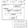
- FIG. It is a block diagram which shows the structure of the vehicle control unit which concerns on Embodiment 1.
- FIG. It is a figure which shows the schematic structure of the vehicle (own vehicle) equipped with the vehicle control unit which concerns on Embodiment 1.
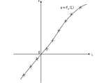
- FIG. It is a flowchart which shows the operation of the reference path generation part. It is a figure which shows the example of a plurality of coordinate points and a reference point in the own vehicle coordinate system. It is a figure which shows the relationship between the path length in FIG. 4 and the x-coordinate (position in the traveling direction of own vehicle) of a coordinate point. It is a figure which shows the relationship between the path length in FIG. 4 and the y coordinate (position in the lateral direction of own vehicle) of a coordinate point.
- FIG. 1 It is a figure for demonstrating the operation of the target value calculation part. It is a block diagram which shows the structure of the vehicle control unit which concerns on Embodiment 4. FIG. It is a block diagram which shows the structure of the vehicle control unit which concerns on Embodiment 5.
- FIG. 1 is a block diagram showing a schematic configuration of the vehicle control unit 200 according to the first embodiment.
- the vehicle control unit 200 is mounted on the vehicle and is connected to the external world sensor 110, the locator 120, the vehicle sensor 130, the EPS (Electric Power Steering) controller 311, the power train controller 312, and the brake controller 313 provided in the vehicle. There is.
- the vehicle on which the vehicle control unit 200 is mounted is referred to as "own vehicle”.
- the outside world sensor 110 is a sensor that detects the position of obstacles, lane markings, etc. that exist around the vehicle.
- the outside world sensor 110 includes, for example, a front camera that detects the position, angle, and curvature of the road marking line, a radar that acquires the position and speed of the preceding vehicle to be followed by the own vehicle, and the like.
- the outside world sensor 110 may be composed of, for example, LiDAR (Light Detection and Ringing), sonar, vehicle-to-vehicle communication device, road-to-vehicle communication device, and the like.
- the locator 120 is a device that distributes map information of the road on which the vehicle should travel and its surroundings based on the position information and map information of the vehicle.
- a method for the locator 120 to acquire the position information of the own vehicle for example, a method of calculating from a positioning signal received from a GNSS (Global Navigation Satellite System) satellite may be used, or a relative feature of a feature around the own vehicle acquired by LiDAR or the like may be used. It may be a method of calculating from the position and the map information.
- GNSS Global Navigation Satellite System
- the vehicle sensor 130 acquires information on the state of the own vehicle, such as the speed, acceleration, direction, and angular velocity of the own vehicle.
- the vehicle sensor 130 includes, for example, a steering angle sensor, a steering torque sensor, a yaw rate sensor, a speed sensor, an acceleration sensor, and the like.
- the EPS controller 311 and the power train controller 312 and the brake controller 313 control the EPS motor 5, the power train unit 6 and the brake unit 7 so as to realize the target values of the steering angle, the driving force and the braking force of the own vehicle, respectively. It is a controller to do.
- the vehicle control unit 200 is a unit that controls the operation of the vehicle, calculates each target value of the steering angle, the driving force, and the braking force of the own vehicle, and inputs the target values to the EPS controller 311, the power train controller 312, and the brake controller 313. do.
- the vehicle control unit 200 is an integrated circuit such as a microprocessor, and has a memory such as a ROM (Read Only Memory) and a RAM (Random Access Memory) for storing various programs, and a CPU (Central Processing Unit) for executing the program.
- the function of the vehicle control unit 200 is realized by the processor executing the program.
- Specific examples of the vehicle control unit 200 include an advanced driver assistance system electronic control unit (ADAS-ECU). Details of the vehicle control unit 200 will be described later.
- ADAS-ECU advanced driver assistance system electronic control unit
- FIG. 2 is a diagram showing a schematic configuration of own vehicle 1 which is a vehicle equipped with a vehicle control unit 200.
- the own vehicle 1 includes a steering wheel 2, a steering shaft 3, a steering unit 4, an EPS motor 5, a power train unit 6, a brake unit 7, a front camera 111, a radar sensor 112, and a GNSS sensor 121.
- the steering wheel 2 is a so-called steering wheel for the driver to operate the own vehicle 1.
- the steering wheel 2 is coupled to the steering shaft 3, and the steering unit 4 is connected to the steering shaft 3.
- the steering unit 4 rotatably supports the front wheels as steering wheels and is rotatably supported by the vehicle body frame. Therefore, the steering torque generated by the operation of the steering wheel 2 of the driver rotates the steering shaft 3, and the steering unit 4 steers the front wheels to the left and right in accordance with the rotation of the steering shaft 3.
- the driver can control the lateral movement amount of the own vehicle 1 when the own vehicle 1 moves forward or backward.
- the steering shaft 3 can also be rotated by the EPS motor 5.
- the EPS controller 311 can freely steer the front wheels independently of the operation of the steering wheel 2 of the driver.
- the vehicle control unit 200 includes a front camera 111, a radar sensor 112, a GNSS sensor 121, a navigation device 122, a steering angle sensor 131, a steering torque sensor 132, a yaw rate sensor 133, a speed sensor 134, an acceleration sensor 135, an EPS controller 311 and a power.
- the train controller 312 and the brake controller 313 are connected.
- the front camera 111 is installed at a position where the lane marking in front of the vehicle can be detected as an image, and detects the front environment of the own vehicle such as lane information and the position of obstacles based on the image information.
- the radar sensor 112 irradiates the radar and detects the reflected wave to output the relative distance and the relative speed of the obstacle with respect to the own vehicle 1.
- the radar sensor 112 well-known radars such as millimeter-wave radar, LiDAR, laser range finder, and ultrasonic radar can be used.
- the outside world sensor 110 shown in FIG. 1 is composed of the front camera 111 and the radar sensor 112. It is also possible to use the front camera 111 as a means for detecting the relative distance and the relative speed of the obstacle.
- the GNSS sensor 121 receives radio waves from the positioning satellite with an antenna and outputs the absolute position and absolute direction of the own vehicle 1 by performing positioning calculation.
- the navigation device 122 has a function of calculating an optimum travel route for a destination (destination) set by the driver, and stores map data including road information of each road constituting the road network.
- Road information is map node data that expresses road alignment, and each map node data includes absolute position (latitude, longitude, altitude), lane width, road curvature, cant angle, inclination angle information, etc. of each node. ing.
- the locator 120 shown in FIG. 1 is composed of the GNSS sensor 121 and the navigation device 122.
- the steering angle sensor 131 detects the steering angle of the steering wheel 2.
- the steering torque sensor 132 detects the steering torque of the steering shaft 3.
- the yaw rate sensor 133 detects the yaw rate of the own vehicle 1.
- the speed sensor 134 detects the speed of the own vehicle 1.
- the acceleration sensor 135 detects the acceleration of the own vehicle 1.
- the vehicle sensor 130 shown in FIG. 1 is composed of a steering angle sensor 131, a steering torque sensor 132, a yaw rate sensor 133, a speed sensor 134, and an acceleration sensor 135.
- FIG. 2 shows a vehicle whose driving force source is only the engine as an example of the own vehicle 1, but the own vehicle 1 includes an electric vehicle whose driving force source is an electric motor and both an engine and an electric motor. It may be a hybrid vehicle used as a driving force source.
- the vehicle control unit 200 includes a coordinate point generation unit 210 and a vehicle control device 201.
- the coordinate point generation unit 210 has a plurality of positions where the own vehicle should travel based on at least one of the road marking line information obtained from the outside world sensor 110, the position information history of the preceding vehicle, and the map information obtained from the locator 120. Generates point sequence information including a plurality of coordinate points representing. For example, when the vehicle control unit 200 performs lane keeping control of the own vehicle, point sequence information is generated at least based on the road lane marking information, and when the vehicle control unit 200 causes the own vehicle to follow the preceding vehicle, at least. Point sequence information is generated based on the position information history of the preceding vehicle, and when the vehicle control unit 200 travels the own vehicle along the route to the destination, coordinate points are generated at least based on the map information.
- the coordinate point generation unit 210 may generate point sequence information from two or more combinations of road lane marking information, position information history, and map information.
- coordinate points generated by the coordinate point generation unit 210 representing the positions where the vehicle should travel are simply referred to as "coordinate points”, and a plurality of coordinate points generated by the coordinate point generation unit 210.
- the point sequence information including the above is simply referred to as "point sequence information”.
- the vehicle control device 201 includes a reference route generation unit 220, a planned mileage calculation unit 230, a target value calculation unit 240, and a vehicle control unit 250.
- the reference path generation unit 220 calculates the path length (distance traced by the coordinate points in chronological order) from the preset reference point to each coordinate point based on the point sequence information generated by the coordinate point generation unit 210.
- a reference path which is a reference path, is generated by performing a polynomial approximation that approximates a plurality of coordinate points with a polynomial that is a function of the path length from the reference point.
- the reference path generation unit 220 acquires point sequence information including a plurality of coordinate points generated by the coordinate point generation unit 210 (step S221).
- each coordinate point is represented by the own vehicle coordinate system based on the position of the own vehicle.
- a coordinate system in which the position of the own vehicle is the origin, the x-coordinate is taken in the direction toward the front of the own vehicle, and the y-coordinate is taken in the direction toward the side of the own vehicle is defined as the own vehicle coordinate system. do. Therefore, the x-coordinate of each coordinate point (x, y) is referred to as "traveling direction position", and the y-coordinate is referred to as "horizontal position".
- the reference route generation unit 220 sets a reference point as a reference for calculating the route length in the vicinity of the own vehicle position (step S222).
- the position of the reference point is set either on the coordinate points, between the coordinate points, or on an extension of a straight line or a curve connecting the coordinate points.
- FIG. 4 shows an example of a reference point.
- the method of setting the reference point is not limited to this example, and any method may be used.
- intersection of x 0 with a curve obtained by approximating multiple coordinate points with a polynomial function or spline function, or the method of subtracting multiple coordinate points from the vehicle position with a curve approximated by a polynomial function or spline function.
- the intersection with the line may be used as a reference point.
- the reference path generation unit 220 obtains the path length L from the reference point set in step S222 to each coordinate point (step S223).
- the distance obtained by linearly tracing the coordinate points from the reference point is defined as the path length L.
- the definition of the route length L is not limited to this.
- the distance obtained by line-integrating a curve obtained by approximating a plurality of coordinate points with a polynomial function or a spline function may be defined as the path length L.
- the coordinate points are obtained as three-dimensional coordinates including the altitude (elevation)
- the three-dimensional distance following the coordinate points from the reference point may be defined as the path length L.
- the planned mileage calculation unit 230 calculates the planned mileage as a three-dimensional distance.
- the reference route generation unit 220 sets each of the x-coordinate (position in the traveling direction of the own vehicle) and the y-coordinate (position in the lateral direction of the own vehicle) of the plurality of coordinate points to the Mth order (M is 1) which is a function of the route length L.
- M is 1
- a polynomial approximation that approximates with the polynomial of the above integers) is performed (step S224). For example, at a plurality of coordinate points illustrated in FIG. 4, the relationship between the route length L and the vehicle traveling direction position x is as shown in FIG. 5, and the relationship between the route length L and the vehicle lateral direction position y is shown in FIG. Will be.
- the reference route generation unit 220 has a polynomial expression f x (L) that approximates the relationship between the route length L and the vehicle traveling direction position x, and a polynomial expression f y that approximates the relationship between the route length L and the vehicle lateral position y. (L) and is obtained.
- the reference route generation unit 220 approximates each of the own vehicle traveling direction position x and the own vehicle lateral direction position y with a cubic polynomial expression.
- the own vehicle traveling direction position x and the own vehicle lateral direction position y are expressed by the following equations 101 and 102, respectively, and the reference route generation unit 220 uses the values of the respective coefficients included in the equations 101 and 102. calculate.
- the point sequence information acquired by the reference route generation unit 220 includes only the x-coordinate (position in the vehicle traveling direction) and the y-coordinate (position in the vehicle lateral direction) of each coordinate point.
- the point sequence information may include other information such as the vehicle speed and yaw rate that the vehicle should take at each coordinate point, the curvature of the road at each coordinate point, the azimuth angle of the road, and the like.
- the reference path generation unit 220 may also approximate the information with a polynomial expression. That is, the reference route generation unit 220 approximates all the information with a polynomial expression according to the content of the point sequence information acquired from the coordinate point generation unit 210 and the parameters for which the vehicle control unit 250 calculates the target value. May be good.
- the target value calculation unit 240 controls the actuator of the own vehicle based on the reference path represented by the polynomial expression generated by the reference route generation unit 220 and the planned mileage of the own vehicle calculated by the planned mileage calculation unit 230. Calculate the target value of each parameter used in. Specifically, the planned mileage calculation unit 230 calculates the target position, which is the target value of the position of the own vehicle after the unit time, and the target azimuth, which is the target value of the azimuth angle of the own vehicle after the unit time. do. Further, the target value calculation unit 240 calculates the target steering angle, which is the target value of the steering angle of the own vehicle after a unit time, from the target position and the target azimuth angle of the own vehicle and the curvature of the road at the target position.
- x-coordinate of the target position of the own vehicle is x-tg and the y-coordinate is y- tg
- x- tg and y- tg are expressed as follows, respectively.
- the target azimuth angle ⁇ tg of the own vehicle and the curvature ⁇ tg of the road can be calculated as follows using a cubic polynomial of x and y.
- the target azimuth angle ⁇ tg of the vehicle and the road may be calculated using a cubic polymorphism as follows.
- the vehicle control unit 250 reduces the error between the position and azimuth angle of the own vehicle at the current time acquired by the vehicle sensor 130 and the target position and target azimuth angle of the own vehicle calculated by the target value calculation unit 240.
- the control target value for the actuator specifically, the target steering angle, the target driving force, and the target braking force are calculated so that the steering angle and speed of the own vehicle become values according to the target curvature of the own vehicle. ..
- the vehicle control unit 250 transmits the target steering angle to the EPS controller 311, transmits the target driving force to the power train controller 312, and transmits the target braking force to the brake controller 313.
- the EPS controller 311 controls the EPS motor 5 so as to realize the target steering angle received from the vehicle control unit 250.
- the powertrain controller 312 controls the powertrain unit 6 so as to realize the target driving force received from the vehicle control unit 250.
- the brake controller 313 controls the brake unit 7 so as to realize the target braking force received from the vehicle control unit 250.
- the EPS controller 311 controls the EPS motor 5 based on the steering torque of the steering wheel 2. Further, in a situation where the driver controls the speed of the own vehicle, the power train controller 312 controls the power train unit 6 based on the amount of depression of the accelerator pedal, and the brake controller 313 controls the power train unit 6 based on the amount of depression of the brake pedal. Controls the brake unit 7.
- the target value calculation unit 240 calculates the target values of the position and azimuth of the own vehicle and the curvature of the road on which the own vehicle travels.
- the reference path generator 220 approximates the yaw rate to be taken by the own vehicle at each coordinate point with a polynomial expression which is a function of the route length from the reference point, and targets the target.
- the value calculation unit 240 may calculate the target yaw rate, which is the target value of the yaw rate of the own vehicle after a unit time, from the polynomial expression and the planned mileage. In that case, the vehicle control unit 250 controls the actuator so that the error between the yaw rate of the own vehicle and the target yaw rate acquired by the vehicle sensor 130 after a unit time becomes small.
- the vehicle control unit 200 has a coordinate point generation unit 210 that generates point sequence information including a plurality of coordinate points representing a plurality of positions to be traveled by the own vehicle, and the point sequence information.
- the vehicle control device 201 which calculates a reference path by polynomially approximating a plurality of coordinate points included in the vehicle, and calculates a target steering angle, a target driving force, and a target braking force for driving the own vehicle along the reference path. To be equipped.
- the vehicle control device 201 calculates the reference path by approximating the plurality of coordinate points to a polynomial expression that is a function of the path length from the reference point, even when the own vehicle makes a 90-degree turn or makes a U-turn, the vehicle control device 201 calculates the reference path. It is possible to accurately express the reference route that the vehicle should travel. As a result, the route followability in the automatic control of the own vehicle is improved.
- the target value calculation unit 230 sets the vehicle speed or the target vehicle speed (Vtg ) of the own vehicle used for calculating the planned mileage of the own vehicle to a negative value.
- 240 can calculate the target position at the time of retreat. Therefore, this embodiment can be applied not only when the own vehicle moves forward but also when the vehicle moves backward.
- the vehicle can be controlled to travel along the forward gaze point, and the occupant of the vehicle can be controlled. It is possible to realize driving that does not give a sense of discomfort.
- the forward gaze point is a point where the driver is expected to gaze when manually driving the own vehicle
- the forward gaze time is defined as the time required for the own vehicle to reach the forward gaze point.
- the EPS controller 311, the power train controller 312, and the brake controller 313 are all connected to the vehicle control unit 200.
- the vehicle control unit 200 controls acceleration / deceleration of the own vehicle. If not, it is not necessary to connect the powertrain controller 312 and the brake controller 313 to the vehicle control unit 200.
- the vehicle control unit 200 is an integrated circuit such as a microprocessor, and is an A / D conversion circuit, a D / A conversion circuit, a processor such as a CPU (Central Processing Unit), a ROM (Read Only Memory), and a RAM. It is equipped with memory such as (RandomAccessMemory).
- the processor of the vehicle control unit 200 processes the information input from the external world sensor 110, the locator 120, and the vehicle sensor 130 according to the program stored in the ROM, thereby processing the above-mentioned coordinate point generation unit 210 and reference path generation unit 220.
- the planned mileage calculation unit 230, the target value calculation unit 240, and the vehicle control unit 250 are realized, and the target steering angle, the target driving force, and the target braking force of the own vehicle are calculated.
- the vehicle control unit 200 acquires point sequence information including information on a plurality of coordinate points on which the vehicle should travel when executed by the processor, and advances the vehicle based on the plurality of coordinate points.
- the planned mileage calculation unit 230 calculates only one planned mileage (Ltg ) of the own vehicle in a unit time, but in the second embodiment, a plurality of unit times having different lengths are calculated. It is used to calculate a plurality of planned mileages corresponding to each of a plurality of unit times. Since the basic configuration and operation of the vehicle control unit 200 of the second embodiment are the same as those of the first embodiment, the description overlapping with the first embodiment will be omitted.
- the planned mileage calculation unit 230 calculates two planned mileages. That is, the planned mileage calculation unit 230 presets the first planned mileage, which is the distance that the own vehicle should travel in the predetermined first unit time, based on the vehicle speed or the target vehicle speed of the own vehicle. The second planned mileage, which is the distance that the own vehicle should travel in the second unit time, is calculated.
- the vehicle speed or target vehicle speed of the own vehicle used for calculating the planned mileage is V tg
- the first unit time is ⁇ t 1
- the second unit time is ⁇ t 2
- the first planned mileage L tg 1 and the second planned travel distance L tg2 of, respectively represented as L tg1 V tg ⁇ t 1
- L tg2 V tg ⁇ t 2.
- the target value calculation unit 240 includes a reference route represented by a polynomial expression generated by the reference route generation unit 220, and the first planned mileage and the second planned mileage of the own vehicle calculated by the planned mileage calculation unit 230. Based on, the target value of the control of the actuator of the own vehicle is calculated. At this time, the target value calculation unit 240 selects and uses either the first planned mileage or the second planned mileage for each parameter to be calculated for the target value.
- planned travel distance calculator 230 the vehicle of the y-coordinate of the target position (target lateral position) y tg and the target azimuth theta tg calculated using the first predetermined travel distance L tg1, curvature of the road ⁇ assuming calculated using the second planned travel distance L tg2 tg, the target lateral position y tg, the curvature kappa tg target azimuth theta tg and roads are respectively calculated as follows.
- the vehicle control unit 250 reduces the error between the position and azimuth angle of the own vehicle at the current time acquired by the vehicle sensor 130 and the target position and target azimuth angle of the own vehicle calculated by the target value calculation unit 240.
- the control target value for the actuator specifically, the target steering angle, the target driving force, and the target braking force are calculated so that the steering angle and speed of the own vehicle become values according to the target curvature of the own vehicle. ..
- the vehicle control unit 250 transmits the target steering angle to the EPS controller 311, transmits the target driving force to the power train controller 312, and transmits the target braking force to the brake controller 313.
- the first unit time ⁇ t 1 is the forward gaze time
- the lateral position and azimuth of the own vehicle are controlled so that the own vehicle travels along the forward gaze point.
- the second unit time ⁇ t 2 is set to 0
- the steering angle of the own vehicle is controlled according to the curvature of the road at the current position of the own vehicle.
- target values at different positions can be set for each parameter, so that control with higher route followability and stability can be performed.
- two planned mileages are used, but three or more are used, and the number of parameters that the vehicle control unit 250 can calculate the target value can be increased at the maximum.
- the target value calculation unit 240 controls the actuator of the own vehicle based on the reference path represented by the polynomial expression generated by the reference route generation unit 220 and the planned mileage of the own vehicle calculated by the planned mileage calculation unit 230. Calculate the target value of. Since the planned mileage L tg is a vector quantity, the target value for controlling the actuator of the own vehicle is also calculated as the vector quantity.
- the target lateral position y tg , the target azimuth angle ⁇ tg, and the target speed V tg of the own vehicle are calculated as follows.
- the vehicle control unit 250 adjusts the dynamics of the vehicle so that the position, azimuth angle, and speed of the own vehicle follow the target values (target values at a plurality of times) at a plurality of points calculated by the target value calculation unit 240.
- a dynamic vehicle model which is a mathematically expressed motion model
- the behavior of the own vehicle is predicted at intervals of the current time 0 to the unit time ⁇ t by N ⁇ ⁇ t, and the desired movement of the own vehicle is obtained.
- the optimum target steering amount or the optimum target steering amount and target acceleration are calculated.
- the predicted vehicle state quantity is N points.
- the vehicle control unit 250 solves the following constrained optimization problem at regular intervals.
- J is an evaluation function
- x is a vehicle state quantity
- u is a control input
- f is a vector value function related to a dynamic vehicle model
- x 0 is an initial value
- g is a vector value function related to a constraint.
- the above optimization problem is treated as a minimization problem, but it can also be treated as a maximization problem by inverting the sign of the evaluation function.
- the above vehicle state quantity x and control input u are set as follows.
- ⁇ is the skid angle
- ⁇ is the yaw rate
- ⁇ is the steering angle
- ⁇ is the steering angular velocity
- ⁇ is the acceleration
- j is the jerk.
- the dynamic vehicle model f uses the following two-wheel model.
- h is a vector value function related to the evaluation item
- h N is a vector value function related to the evaluation item at the end (prediction point N)
- W and W N are weight matrices, which are diagonal matrices having weights for each evaluation item as diagonal components, and can be appropriately changed as parameters.
- the vector value functions h and h N related to the evaluation items are set as follows in order to steer and control the vehicle so as to travel in the center of the lane with a small control input and to make the vehicle speed follow the target vehicle speed.
- evaluation items are set to evaluate the route following error, the angle following error, the steering speed, the vehicle speed following error, and the jerk.
- acceleration and acceleration are set. Jerk and the like may be added to the evaluation items.
- the function g is for setting the vehicle state quantity x and the upper limit value and the lower limit value (hereinafter, also referred to as "upper and lower limit values") of the control input u in the constrained optimization problem, and is optimized. Is executed under the condition of g (x, u) ⁇ 0.
- the upper limit values of the steering speed ⁇ and the jerk j are set to ⁇ , ⁇ j (> 0), and the lower limit values are set to _ ⁇ , _j ( ⁇ 0).
- the function g is set as follows (the symbol "_” means the underscore attached to the character following it, and the symbol " ⁇ ” means the overbar attached to the character following it).
- upper and lower limit values may be set for the direction, yaw rate, acceleration, etc. in order to secure the riding comfort
- upper and lower limit values of the vehicle speed may be set in order to strictly adhere to the speed limit.
- the vehicle control unit 250 calculates the target steering angle and target acceleration of the own vehicle and transmits them to the EPS controller 311, the power train controller 312, and the brake controller 313.
- the vehicle control unit 250 can calculate the target steering angle and the target acceleration with a small accumulation of errors for a plurality of target positions, so that the route followability of the own vehicle is improved. Furthermore, the effect of improving the riding comfort can be obtained by evaluating the yaw rate and the acceleration with the evaluation function.
- FIG. 8 is a block diagram showing the configuration of the vehicle control unit 200 according to the fourth embodiment.
- the configuration of the vehicle control unit 200 of the fourth embodiment is the configuration of the vehicle control device 201 with the calculation result storage unit 260 added to the configuration of FIG.
- the calculation result storage unit 260 stores the calculation result of the vehicle control unit 250. Since other configurations are the same as those of the first to third embodiments, the description overlapping with the first to third embodiments will be omitted.
- the planned mileage calculation unit 230 calculates the planned mileage, which is the distance that the own vehicle should travel in the unit time ⁇ t, using the information of the predicted speed stored in the calculation result storage unit 260. Further, when the present embodiment is applied to the third embodiment, the planned mileage calculation unit 230 uses the speed information stored in the calculation result storage unit 260 to display the speed from the current time to N ⁇ ⁇ t ahead. Calculate the planned mileage for each unit time ⁇ t.
- the planned mileage calculation unit 230 calculates the planned mileage by using the speed calculation result by the vehicle control unit 250, that is, the calculation result of the speed of the own vehicle predicted in the future.
- the vehicle control unit 250 can generate a route that is easier to travel, and the ride quality of the vehicle is improved.
- FIG. 9 is a block diagram showing the configuration of the vehicle control unit 200 according to the fourth embodiment.
- the configuration of the vehicle control unit 200 of the fourth embodiment is almost the same as the configuration of FIG. 1, but the result of polynomial approximation of the speed of the own vehicle is input from the reference route generation unit 220 to the planned mileage calculation unit 230.
- the planned mileage calculation unit 230 calculates the planned mileage, which is the distance that the vehicle should travel in the unit time ⁇ t, by using the polynomial expression of the speed of the own vehicle acquired from the reference route generation unit 220. Since other configurations are the same as those of the first to third embodiments, the description overlapping with the first to third embodiments will be omitted.
- the point sequence information includes the vehicle speed information that the own vehicle should take at each coordinate point
- the reference route generation unit 220 further determines the speed that the own vehicle should take at each coordinate point. , Performs polynomial approximation that approximates with a polynomial that is a function of the path length from the reference point.
- the reference route generation unit 220 approximates the speed that the own vehicle should take with a cubic polynomial expression.
- the speed V that the vehicle should take is represented by the following third-order polynomial expression.
- a simultaneous equation of a cubic polynomial of the speed V calculated by the reference route generation unit 220 and a relational expression L V ⁇ t of the distance L when the vehicle travels at the vehicle speed V for a unit time ⁇ t is obtained. by solving, it calculates the own vehicle will travel distance L tg in a unit time Delta] t.
- the distance when the vehicle travels for a unit time ⁇ t at a speed calculated from a plurality of coordinate points acquired from the coordinate point generation unit 210 is calculated as the planned travel distance Ltg.
- the path followability of is improved.
Landscapes
- Engineering & Computer Science (AREA)
- Automation & Control Theory (AREA)
- Transportation (AREA)
- Mechanical Engineering (AREA)
- Human Computer Interaction (AREA)
- Chemical & Material Sciences (AREA)
- Combustion & Propulsion (AREA)
- Control Of Driving Devices And Active Controlling Of Vehicle (AREA)
- Steering Control In Accordance With Driving Conditions (AREA)
Priority Applications (4)
| Application Number | Priority Date | Filing Date | Title |
|---|---|---|---|
| DE112020006881.1T DE112020006881T5 (de) | 2020-03-13 | 2020-03-13 | Fahrzeug-steuerungseinrichtung |
| JP2022505685A JP7332785B2 (ja) | 2020-03-13 | 2020-03-13 | 車両制御装置 |
| PCT/JP2020/011041 WO2021181652A1 (ja) | 2020-03-13 | 2020-03-13 | 車両制御装置 |
| US17/789,542 US20230030368A1 (en) | 2020-03-13 | 2020-03-13 | Vehicle control device |
Applications Claiming Priority (1)
| Application Number | Priority Date | Filing Date | Title |
|---|---|---|---|
| PCT/JP2020/011041 WO2021181652A1 (ja) | 2020-03-13 | 2020-03-13 | 車両制御装置 |
Publications (1)
| Publication Number | Publication Date |
|---|---|
| WO2021181652A1 true WO2021181652A1 (ja) | 2021-09-16 |
Family
ID=77671059
Family Applications (1)
| Application Number | Title | Priority Date | Filing Date |
|---|---|---|---|
| PCT/JP2020/011041 Ceased WO2021181652A1 (ja) | 2020-03-13 | 2020-03-13 | 車両制御装置 |
Country Status (4)
| Country | Link |
|---|---|
| US (1) | US20230030368A1 (https=) |
| JP (1) | JP7332785B2 (https=) |
| DE (1) | DE112020006881T5 (https=) |
| WO (1) | WO2021181652A1 (https=) |
Cited By (1)
| Publication number | Priority date | Publication date | Assignee | Title |
|---|---|---|---|---|
| JP2024535632A (ja) * | 2021-10-15 | 2024-09-30 | 三菱電機株式会社 | 車両のモーションを制御するためのシステムおよび方法 |
Families Citing this family (2)
| Publication number | Priority date | Publication date | Assignee | Title |
|---|---|---|---|---|
| WO2024036431A1 (zh) * | 2022-08-15 | 2024-02-22 | 华为技术有限公司 | 一种控制方法以及相关设备 |
| US12522215B2 (en) * | 2023-03-31 | 2026-01-13 | Torc Robotics, Inc. | Lane change path generation using piecewise clothoid segments |
Citations (4)
| Publication number | Priority date | Publication date | Assignee | Title |
|---|---|---|---|---|
| US20080275602A1 (en) * | 2005-05-24 | 2008-11-06 | Peake John W | Method and apparatus for automatic vehicle guidance using continuous 2-D poly-point path |
| JP2019525148A (ja) * | 2016-07-21 | 2019-09-05 | モービルアイ ビジョン テクノロジーズ リミテッド | 自律車両ナビゲーションのための疎な地図並びにレーン測定値のクラウドソーシング及び配信 |
| JP2020001678A (ja) * | 2018-06-27 | 2020-01-09 | バイドゥ・ユーエスエイ・リミテッド・ライアビリティ・カンパニーBaidu USA LLC | 重み付け幾何学的コストを有する区分的螺旋曲線を使用した基準線平滑化方法 |
| JP2020037339A (ja) * | 2018-09-05 | 2020-03-12 | 三菱電機株式会社 | 衝突回避装置 |
Family Cites Families (4)
| Publication number | Priority date | Publication date | Assignee | Title |
|---|---|---|---|---|
| AU2010295227B2 (en) * | 2009-09-15 | 2015-02-05 | Technological Resources Pty. Limited | A system and method for autonomous navigation of a tracked or skid-steer vehicle |
| JP6409346B2 (ja) * | 2014-06-04 | 2018-10-24 | 株式会社デンソー | 移動距離推定装置 |
| JP6910973B2 (ja) | 2018-02-02 | 2021-07-28 | 日立Astemo株式会社 | 車両制御装置及びその制御方法並びに車両制御システム |
| US11500385B2 (en) * | 2019-09-30 | 2022-11-15 | Zoox, Inc. | Collision avoidance perception system |
-
2020
- 2020-03-13 WO PCT/JP2020/011041 patent/WO2021181652A1/ja not_active Ceased
- 2020-03-13 JP JP2022505685A patent/JP7332785B2/ja active Active
- 2020-03-13 DE DE112020006881.1T patent/DE112020006881T5/de not_active Withdrawn
- 2020-03-13 US US17/789,542 patent/US20230030368A1/en active Pending
Patent Citations (4)
| Publication number | Priority date | Publication date | Assignee | Title |
|---|---|---|---|---|
| US20080275602A1 (en) * | 2005-05-24 | 2008-11-06 | Peake John W | Method and apparatus for automatic vehicle guidance using continuous 2-D poly-point path |
| JP2019525148A (ja) * | 2016-07-21 | 2019-09-05 | モービルアイ ビジョン テクノロジーズ リミテッド | 自律車両ナビゲーションのための疎な地図並びにレーン測定値のクラウドソーシング及び配信 |
| JP2020001678A (ja) * | 2018-06-27 | 2020-01-09 | バイドゥ・ユーエスエイ・リミテッド・ライアビリティ・カンパニーBaidu USA LLC | 重み付け幾何学的コストを有する区分的螺旋曲線を使用した基準線平滑化方法 |
| JP2020037339A (ja) * | 2018-09-05 | 2020-03-12 | 三菱電機株式会社 | 衝突回避装置 |
Cited By (2)
| Publication number | Priority date | Publication date | Assignee | Title |
|---|---|---|---|---|
| JP2024535632A (ja) * | 2021-10-15 | 2024-09-30 | 三菱電機株式会社 | 車両のモーションを制御するためのシステムおよび方法 |
| JP7724976B2 (ja) | 2021-10-15 | 2025-08-18 | 三菱電機株式会社 | 車両のモーションを制御するためのシステムおよび方法 |
Also Published As
| Publication number | Publication date |
|---|---|
| DE112020006881T5 (de) | 2023-01-26 |
| JPWO2021181652A1 (https=) | 2021-09-16 |
| JP7332785B2 (ja) | 2023-08-23 |
| US20230030368A1 (en) | 2023-02-02 |
Similar Documents
| Publication | Publication Date | Title |
|---|---|---|
| US10988139B2 (en) | Vehicle position control method and device vehicle position control device for correcting position in drive-assisted vehicle | |
| US10671070B2 (en) | PID embedded LQR for autonomous driving vehicles (ADVS) | |
| EP3629121B1 (en) | A curvature corrected path sampling system for autonomous driving vehicles | |
| CN110877611B (zh) | 障碍物回避装置及障碍物回避路径生成装置 | |
| EP3521963B1 (en) | Dynamically adjustable reference line sampling point density for autonomous vehicles | |
| US9796416B2 (en) | Automated driving apparatus and automated driving system | |
| US9244462B2 (en) | Vehicle trajectory planning for autonomous vehicles | |
| US20190248411A1 (en) | Trajectory tracking for vehicle lateral control using neural network | |
| US11731692B2 (en) | Driving support device that performs steering control and deceleration control for avoiding an object | |
| US10534364B2 (en) | Method and system for autonomous vehicle speed following | |
| CN110877610A (zh) | 碰撞回避装置 | |
| US11377112B2 (en) | Low-speed, backward driving vehicle controller design | |
| US10953876B2 (en) | Target vehicle speed generation method and target vehicle speed generation device for driving-assisted vehicle | |
| JP7106872B2 (ja) | 車両の自動運転制御装置及び自動運転制御方法 | |
| JP6618653B1 (ja) | 走行経路生成装置および車両制御装置 | |
| CN115447615B (zh) | 基于车辆运动学模型预测控制的轨迹优化方法 | |
| JP7332785B2 (ja) | 車両制御装置 | |
| JP7454122B2 (ja) | 車両制御装置 | |
| JP2018030412A (ja) | 運転支援制御装置 | |
| US20240326862A1 (en) | Traveling trajectory generating apparatus | |
| JP7036284B1 (ja) | 制御演算装置および制御演算方法 | |
| JP7845039B2 (ja) | 車両の運転支援方法及び運転支援装置 | |
| JP7241800B2 (ja) | 車両制御装置及び車両制御方法 | |
| JP2025168953A (ja) | 操舵制御装置 | |
| JP2023158340A (ja) | 車両制御装置 |
Legal Events
| Date | Code | Title | Description |
|---|---|---|---|
| 121 | Ep: the epo has been informed by wipo that ep was designated in this application |
Ref document number: 20924841 Country of ref document: EP Kind code of ref document: A1 |
|
| ENP | Entry into the national phase |
Ref document number: 2022505685 Country of ref document: JP Kind code of ref document: A |
|
| 122 | Ep: pct application non-entry in european phase |
Ref document number: 20924841 Country of ref document: EP Kind code of ref document: A1 |