WO2021181609A1 - 冷蔵庫 - Google Patents
冷蔵庫 Download PDFInfo
- Publication number
- WO2021181609A1 WO2021181609A1 PCT/JP2020/010838 JP2020010838W WO2021181609A1 WO 2021181609 A1 WO2021181609 A1 WO 2021181609A1 JP 2020010838 W JP2020010838 W JP 2020010838W WO 2021181609 A1 WO2021181609 A1 WO 2021181609A1
- Authority
- WO
- WIPO (PCT)
- Prior art keywords
- partition plate
- main body
- refrigerator
- door
- end surface
- Prior art date
- Legal status (The legal status is an assumption and is not a legal conclusion. Google has not performed a legal analysis and makes no representation as to the accuracy of the status listed.)
- Ceased
Links
Images










Classifications
-
- F—MECHANICAL ENGINEERING; LIGHTING; HEATING; WEAPONS; BLASTING
- F25—REFRIGERATION OR COOLING; COMBINED HEATING AND REFRIGERATION SYSTEMS; HEAT PUMP SYSTEMS; MANUFACTURE OR STORAGE OF ICE; LIQUEFACTION SOLIDIFICATION OF GASES
- F25D—REFRIGERATORS; COLD ROOMS; ICE-BOXES; COOLING OR FREEZING APPARATUS NOT OTHERWISE PROVIDED FOR
- F25D23/00—General constructional features
- F25D23/02—Doors; Covers
Definitions
- This disclosure relates to a refrigerator equipped with a double door.
- the number of refrigerators equipped with temperature sensors and humidity sensors has been increasing in order to realize optimum operation according to the environment in which the refrigerator is installed.
- the refrigerating room door is divided into left and right, and a heater or the like is installed on the partition plate between the refrigerating room doors.
- the partition plate is usually attached to either the left or right refrigerating room door, hinged to the refrigerating room door at the upper part and the lower part, and the refrigerating room door is fixed by the protrusion of the guide part installed at the upper part of the refrigerating room. A structure that rotates when opening and closing the door is adopted.
- the length of the partition plate in the longitudinal direction is made shorter than the height of the opening of the refrigerator compartment.
- the partition plate is installed so that a certain gap is formed up and down between the partition plate and the opening of the refrigerator compartment.
- gasket fins are provided on the upper and lower parts of the gaskets of the left and right refrigerating chamber doors, and when the left and right refrigerating chamber doors are closed, the left and right gasket fins overlap to create a gap. It is designed to be blocked.
- the cold air of the refrigerating chamber directly hits the back side of the upper and lower gasket fins, and the air volume is set to be larger on the upper side of the refrigerating chamber than on the lower side, so that the upper gasket fins are easily exposed to dew. ..
- the gasket fin may be heated or prevented from being cooled.
- the amount of heat generated by the heater in the partition plate may be increased, but simply increasing the amount of heat generated may reduce energy efficiency, so it is necessary to consider a means of not cooling.
- Patent Document 1 a ball caster is installed on the lower surface of the double door near the center, and the ball caster is mounted on the lower front surface of the refrigerator housing to open the double door when the door is closed.
- a technique for laying a guide rail that supports a type door in a fixed position has been reported. According to this technique, the double door can be normally closed without leaving a gap between the double door and the refrigerator housing.
- Patent Document 1 it is not clear whether the gap between the upper end surface of the partition plate and the upper front opening of the refrigerator compartment can be reduced when the double door is closed. Further, since the ball casters are installed on the lower surface of the partition plate and the guide rails are installed on the floor surface of the refrigerator compartment, the ball casters and guide rails are installed in the refrigerator in which the refrigerator compartment is installed at the top of the refrigerator. There was a problem that it became an obstacle and was not easy to use.
- the present disclosure has been made to solve the above problems, while reducing the gap between the upper end surface of the partition plate and the upper front opening of the refrigerator compartment when the double door is closed.
- the purpose is to provide a refrigerator that can suppress the deterioration of usability.
- the refrigerator according to the present disclosure includes a housing having an outer shell and a refrigerating chamber inside, and left and right double doors provided on the front surface of the housing and opening and closing the front opening of the refrigerating chamber.
- a partition plate that is rotatably attached to one of the left and right double doors to prevent outside air from entering the refrigerating room, and a guide member provided in the lower front part of the ceiling of the refrigerating room.
- the partition plate is provided on the upper and lower sides and is supported by the upper hinge member and the lower hinge member fixed to the inner surface of the double door, and the upper hinge member and the lower hinge member.
- the main body When the double door is closed, the main body is provided with a main body that is guided by the guide member to rotate when the attached double door is opened and closed, and the double door to which the partition plate is attached is closed. Compared to the open state, the main body is moved upward, and the upper end surface of the main body is in contact with the lower surface of the guide member.
- the main body in the closed state of the double door to which the partition plate is attached, the main body is moved upward as compared with the open state of the double door.
- the upper end surface of the portion is in contact with the lower surface of the guide member. Therefore, when the double door is closed, the gap between the upper end surface of the partition plate and the upper front opening of the refrigerator compartment can be reduced. Further, since the ball casters and the guide rails are not required, it is possible to suppress the deterioration of usability.
- FIG. It is a front view of the refrigerator which concerns on Embodiment 1.
- FIG. It is a perspective view which looked at the refrigerator which concerns on Embodiment 1 from above.
- FIG. It is an exploded perspective view which shows the structure of the right door of the refrigerating room of the refrigerator which concerns on Embodiment 1.
- FIG. It is a figure which shows the refrigerant circuit of the refrigerator which concerns on Embodiment 1.
- FIG. It is a connection diagram of the refrigerant pipe in the refrigerator which concerns on Embodiment 1.
- FIG. It is a connection diagram of the refrigerant pipe by the modification of the inside of the refrigerator which concerns on Embodiment 1.
- FIG. It is a vertical sectional view of the upper part of the refrigerator which concerns on Embodiment 1.
- FIG. It is an exploded view of the partition plate of the refrigerator which concerns on Embodiment 1.
- FIG. It is a schematic diagram which shows the cross section around the aluminum foil heater which constitutes the partition plate of the refrigerator which concerns on Embodiment 1, and the detail of a cord-shaped heater.
- FIG. 5 is a view of the left door of the refrigerator compartment and the partition plate of the refrigerator according to the first embodiment as viewed from the inside of the refrigerator. It is an enlarged view of the part A of FIG. It is an enlarged view of the B part of FIG. It is a vertical cross-sectional view of the rotation axis of FIG. FIG.
- FIG. 5 is an enlarged view of the vicinity of the lower hinge member of the partition plate in the state where the left door of the refrigerator compartment according to the first embodiment is open.
- FIG. 5 is an enlarged view of the vicinity of the lower hinge member of the partition plate while the left door of the refrigerator refrigerator according to the first embodiment is being opened and closed. It is an enlarged view around the lower hinge member of the partition plate in the closed state of the refrigerating room left door of the refrigerator which concerns on Embodiment 1.
- FIG. FIG. 5 is an enlarged view of the vicinity of the upper cover member of the partition plate showing a state in which the left door of the refrigerator compartment according to the first embodiment is closed. It is a figure which looked at the cross section of the upper part of the refrigerator shown in FIG. 18 from the bottom.
- FIG. 19 is a view showing a state in which the left door of the refrigerator compartment is further closed as compared with FIG.
- FIG. 20 is a view showing a state in which the left door of the refrigerator compartment is further closed as compared with FIG.
- FIG. 1 is a cross-sectional view taken along the line DD of FIG. It is a cross-sectional arrow view of the same position as FIG. 23 of the conventional refrigerator.
- FIG. 1 is a cross-sectional view taken along the line DD of FIG. It is a cross-sectional arrow view of the same position as FIG. 23 of the conventional refrigerator.
- It is an enlarged perspective view around the upper hinge member by the modification of the refrigerator which concerns on Embodiment 1.
- FIG. It is a vertical sectional view of the refrigerator which concerns on Embodiment 2.
- FIG. It is an enlarged perspective view of the upper part of the partition plate by the modification of the refrigerator which concerns on Embodiment 2.
- FIG. 1 is a cross-sectional view taken along the line
- FIG. 1 is a front view of the refrigerator 100 according to the first embodiment.
- FIG. 2 is a perspective view of the refrigerator 100 according to the first embodiment as viewed from above.
- directional terms such as “top”, “bottom”, “right”, “left”, “front”, “rear”, etc. are used as appropriate for ease of understanding. These terms are for illustration purposes only and are not intended to limit embodiments.
- "upper”, “lower”, “right”, “left”, “front”, “rear” and the like are used in a state where the refrigerator 100 is viewed from the front.
- the refrigerator 100 includes a housing 101 that constitutes an outer shell, and a plurality of storage chambers are provided inside the housing 101.
- a storage room a refrigerating room 1, an ice making room 2, a small freezing room 3, a freezing room 4, and a vegetable room 5 are provided.
- the refrigerator compartment 1 is provided at the uppermost stage of the refrigerator 100, and the front opening is closed by two double doors so as to be openable and closable. These two double doors are provided on the front surface of the housing 101.
- these two double doors are composed of a refrigerating room left door 6 and a refrigerating room right door 7, and there is outside air between the refrigerating room left door 6 and the refrigerating room right door 7.
- a partition plate 8 is provided to prevent the intrusion of the door. The details of the partition plate 8 will be described later.
- an ice making chamber 2 and a small freezer compartment 3 are arranged in parallel so that the storage chamber is pulled out to the user side when the drawer door (not shown) is pulled out.
- a vegetable compartment 5 is provided at the bottom of the refrigerator 100, and a freezing chamber 4 is provided above the vegetable compartment 5.
- the freezing chamber 4 is provided below the ice making chamber 2 and the small freezing chamber 3 arranged in parallel on the left and right, and above the vegetable compartment 5.
- the freezing chamber 4 and the vegetable compartment 5 also have a configuration in which the storage chamber is pulled out to the user side when the drawer door (not shown) is pulled out.
- each storage room is not limited to the first embodiment, and if the configuration is such that two double doors are provided and a partition plate 8 is provided between the doors, the arrangement of each storage room is provided. Does not matter.
- the refrigerator 100 is equipped with an outside air temperature sensor 9 and an outside air humidity sensor 10.
- the outside air temperature sensor 9 detects the outside air temperature, which is the outside air temperature of the refrigerator 100.
- the outside air humidity sensor 10 detects the outside air humidity, which is the outside air humidity of the refrigerator 100.
- the outside air temperature sensor 9 and the outside air humidity sensor 10 can be installed anywhere as long as they can detect the outside air temperature and the outside air humidity. However, it is desirable that the outside air temperature sensor 9 and the outside air humidity sensor 10 are installed at a position that is not affected by the operation of the refrigerator 100, for example, a position that is not affected by the temperature effect of the side condensing pipe that is attached and fixed to the inside of the side surface. Therefore, the location where the outside air temperature sensor 9 and the outside air humidity sensor 10 are installed may not be affected by the heat of the condensing pipe or the like as long as it is inside the hinge cover member 11 provided on the upper side of the left door 6 of the refrigerator compartment.
- FIG. 3 is an exploded perspective view showing the configuration of the left door 6 of the refrigerator 100 of the refrigerator 100 according to the first embodiment.
- FIG. 4 is an exploded perspective view showing the configuration of the refrigerating room right door 7 of the refrigerator 100 according to the first embodiment.
- the refrigerating room left door 6 and the refrigerating room right door 7 are composed of resin cap parts 96 and 97 on the top, bottom, left and right, the inner surface of the door is composed of resin inner plates 87 and 88, and the door surface is made of glass. It is composed of surface panels 98 and 99.
- the refrigerating room left door 6 and the refrigerating room right door 7 are composed of cap parts 96 and 97, inner plates 87 and 88, and door surface panels 98 and 99 on six surfaces. Further, the inside of the refrigerating room left door 6 and the refrigerating room right door 7 is filled with a urethane foam heat insulating material (not shown). Further, in the refrigerating room left door 6, a partition plate 8 for closing the space between the refrigerating room right door 7 and the refrigerating room right door 7 is hinged to the central side surface of the inner plate 87 at the upper and lower portions so as to rotate when the door is opened and closed. ing.
- the refrigerating room left door 6 is provided with a setting operation unit 103 that allows the user to operate the temperature setting of each storage room and the mode setting such as the energy saving mode and the dew-covering countermeasure mode.
- the partition plate 8 and the setting operation unit 103 may be provided on the right door 7 of the refrigerator compartment.
- gaskets 62 and 64 containing magnets are attached to the left door 6 of the refrigerator compartment and the right door 7 of the refrigerator compartment.
- the gaskets 62 and 64 are in close contact with the front flange portion 70 (see FIGS. 6 and 7 described later) around the front opening of the refrigerating chamber 1 and the partition plate 8.
- Gasket fins 63 and 75 are formed on the vertical sides of the gaskets 62 and 64 that are in close contact with the partition plate 8, that is, the upper and lower parts of the right vertical side of the gasket 62 and the upper and lower parts of the left vertical side of the gasket 64.
- , 65, and 76 are provided, respectively.
- the upper gasket fin 63 and the gasket fin 65 are in close contact with the partition plate 8 and the front flange portion 70 of the refrigerating chamber 1.
- the contact surface between the upper end surface 72 of the partition plate 8 described later and the flat lower surface 73 of the guide member 71 provided on the ceiling 69 of the refrigerating chamber 1 is closed (see FIG. 18 described later).
- the lower gasket fins 75 and the gasket fins 76 are in close contact with the partition plate 8 and the front flange portion 70 of the refrigerating chamber 1, and are formed between the lower end of the partition plate 8 and the lower surface of the refrigerating chamber 1 described later. It is designed to close the gap (hereinafter referred to as the lower gap).
- three pockets 26 for storage are attached to the inside of the refrigerator compartment left door 6 and the refrigerator compartment right door 7 along the height direction.
- the number of pockets 26 attached to the refrigerator compartment left door 6 and the refrigerator compartment right door 7 is not limited to three, and may be two or less or four or more.
- FIG. 5 is a diagram showing a refrigerant circuit 104 of the refrigerator 100 according to the first embodiment.
- FIG. 6 is a connection diagram of a refrigerant pipe inside the refrigerator 100 according to the first embodiment.
- FIG. 7 is a connection diagram of a refrigerant pipe according to a modified example of the inside of the refrigerator 100 according to the first embodiment.
- the arrow shown in FIG. 5 indicates the flow of the refrigerant.
- the right front side is the front side of the refrigerator 100.
- the refrigerator 100 includes a refrigerant circuit 104 in which a refrigerant circulates.
- the refrigerant circuit 104 includes a compressor 12, a fin tube type machine room condenser 13, a left side side condensing pipe 14, a ceiling surface condensing pipe 15, a back condensing pipe 16, and a right side side condensing pipe 17. It includes a dew-prevention pipe 18, a dryer 19, a capillary tube 20 which is a decompression device, a cooler 21, a muffler (liquid reservoir) 22, and a suction pipe 23.
- the machine room condenser 13, the left side side condensing pipe 14, the ceiling surface condensing pipe 15, the back condensing pipe 16, the right side condensing pipe 17, and the dew condensation prevention pipe 18 are condensing pipes.
- the compressor 12, the machine room condenser 13, and the dryer 19 are installed in a machine room (not shown) provided in the lower part on the back side of the refrigerator 100.
- the ceiling surface condensing pipe 15 extends from the left side side condensing pipe 14 on the left side surface to the ceiling surface and is connected to the ceiling surface condensing pipe 15.
- the ceiling surface condensing pipe 15 may extend from the right side side condensing pipe 17 on the right side surface to the ceiling surface and be connected.
- the left side side condensing pipe 14, the ceiling surface condensing pipe 15, the back condensing pipe 16, and the right side side condensing pipe 17 are fixed to the inner surface of the metal outer box of the refrigerator 100 with aluminum tape (not shown).
- the refrigerator 100 is provided in the machine room, is provided above the machine room cooling fan (not shown) for cooling the machine room condenser 13 and the compressor 12, and the cooler 21, and circulates cold air into the refrigerator. It is equipped with an internal cooling fan (not shown).
- two capillaries 20 may be installed or a plurality of coolers 21 may be installed.
- a three-way valve is installed on the upstream side of the capillaries 20.
- the machine room condenser 13, the ceiling surface condensing pipe 15, and the back condensing pipe 16 may not be provided as long as the condensing capacity can be obtained only by the left side side condensing pipe 14 and the right side side condensing pipe 17. .
- the dew condensation prevention pipe 18 has a refrigerating chamber 1, an ice making chamber 2, a small freezing chamber 3, a freezing chamber 4, and a vegetable compartment 5, that is, a front flange portion 70 so as to surround each storage chamber. Is located in. Further, the dew condensation prevention pipe 18 is connected to the right side condensing pipe 17 at the lower right back side, and is connected to the dryer 19 arranged in the machine room at the lower left back side.
- the dew condensation prevention pipe 18 has a front flange portion so as to surround each storage chamber except the refrigerating chamber 1. It may be arranged at 70. That is, the dew condensation prevention pipe 18 does not have to be arranged on the upper side and the left and right front flange portions 70 of the refrigerating chamber 1.
- the case where the heat insulating performance between the wall surface of the refrigerating chamber 1 and the outer box is good means, for example, the distance between the wall surface of the refrigerating chamber 1 and the outer box, that is, the case where the heat insulating thickness is large, or refrigeration. This is the case where the vacuum heat insulating material is arranged between the wall surface of the room 1 and the outer box.
- the temperature of the front flange portion 70 around the partition plate 8 is set.
- the temperature is lower than that in the case where the dew condensation prevention pipe 18 is arranged.
- the upper end surface 72 of the partition plate 8 and the flat lower surface 73 of the guide member 71 provided on the ceiling 69 of the refrigerating chamber 1 The temperature of the gasket fins 63 and 65 that close the contact surface of the above does not decrease. Then, by reducing the length of the dew condensation prevention pipe 18 to be arranged, the material cost and the manufacturing cost required when arranging the dew condensation prevention pipe 18 can be reduced.
- FIG. 8 is a vertical sectional view of the upper part of the refrigerator 100 according to the first embodiment.
- a control device 29 is provided on the back side of the refrigerator 100.
- the control device 29 is composed of, for example, dedicated hardware or a CPU (also referred to as a central processing unit, a processing unit, an arithmetic unit, a microprocessor, or a processor) that executes a program stored in a memory. There is.
- a refrigerating room temperature sensor 32 for detecting the temperature of the refrigerating room 1 (hereinafter referred to as a refrigerating room temperature) is provided in the refrigerating room 1.
- the refrigerating room temperature sensor 32 may be installed at any position in the refrigerating room 1 as long as it can detect the temperature of the refrigerating room.
- the control device 29 blows or shuts off cold air to the refrigerating room 1 based on the refrigerating room temperature detected by the refrigerating room temperature sensor 32 by opening and closing the baffle 85 of the refrigerating room damper device 31.
- the refrigerator compartment damper device 31 is provided in the refrigerator compartment outlet air passage 86 formed on the back side of the refrigerator 100.
- the refrigerating chamber temperature sensor 32 includes a heater (not shown) installed in the refrigerating chamber 1 for temperature compensation and an aluminum foil heater 43 described later (see FIG. 9 described later) installed in the partition plate 8. ) Is used to control energization.
- arrows 37 to 41 in FIG. 8 indicate the flow of wind from an outlet (not shown) formed on the inner wall of the refrigerating chamber 1
- arrows 33 to 36 indicate the flow of wind in the refrigerating chamber 1. It shows the transfer of heat.
- Arrow 33 indicates heat intrusion from the ceiling 69 of the refrigerator compartment 1.
- Arrow 34 indicates heat intrusion from the back surface of the refrigerating chamber 1.
- Arrow 35 indicates heat intrusion from the refrigerating room left door 6 or the refrigerating room right door 7.
- the arrow 36 indicates the transfer of heat from the refrigerating chamber 1 to the ice making chamber 2 or the small freezing chamber 3 whose temperature is lower than that of the refrigerating chamber 1.
- FIG. 8 is a cross-sectional view and is not shown.
- the size of the arrow indicates the amount of wind or heat, respectively.
- the arrow 37 indicates that the air volume is larger than that of the arrow 41
- the arrow 33 indicates that the heat transfer amount is larger than that of the arrow 36. There is.
- the refrigerating room 1 is divided into a plurality of shelves 30. Further, a chilled chamber 27 (about 0 ° C.) lower than the temperature (about 3 ° C.) of the refrigerating chamber 1 is provided under the lowermost shelf 30 in the refrigerating chamber 1, and the chilled chamber 27 is provided with food. A chilled case 28 for storing the above is provided. Further, the wind indicated by arrows 37 to 41 is blown from each outlet to each portion of the wall on the back side of the refrigerating chamber 1 partitioned by the plurality of shelves 30.
- the upper side of the refrigerating chamber 1 has a large leakage of heat (see arrow 33) from the ceiling 69 of the refrigerating chamber 1. Therefore, regarding the amount of air blown from the outlet formed on the wall on the back side of the refrigerating chamber 1, the air volume at the uppermost stage is the largest in each portion of the refrigerating chamber 1 partitioned by a plurality of shelves 30. .. Further, since the temperature distribution of each of the partitioned portions in the refrigerating chamber 1 is kept within a certain width, the upper portion of the partition plate 8 tends to be cooled more easily than the lower portion.
- the energization rate of the aluminum foil heater 43 in the partition plate 8 has been made higher than necessary so that dew does not adhere to the upper gasket fins 63 and 65.
- a gap (hereinafter referred to as an upper gap) formed between the upper end surface 72 of the partition plate 8 of the refrigerator and the flat lower surface 73 of the guide member 71 provided on the ceiling 69 of the refrigerating chamber 1 is provided. Since the surface temperature of the gasket fins 63 and 65 to close is large on the upper side of the refrigerating chamber 1, the surface temperature tends to be less likely to rise than the surface temperature of the gasket fins 75 and 76 to close the lower gap. Therefore, conventionally, the energization rate to the aluminum foil heater 43 has been determined according to the surface temperature of the gasket fins 63 and 65 that close the upper gap.
- FIG. 9 is an exploded view of the partition plate 8 of the refrigerator 100 according to the first embodiment.
- an aluminum foil heater 43 having a meandering pattern formed along the longitudinal direction is attached to the back side of the metal surface sheet metal 42 which is the front surface side of the partition plate 8.
- a resin surface frame type resin member 44 is attached to the back side of the aluminum foil heater 43 by fitting its claws (not shown) to the claw receiving portion 57 of the surface sheet metal 42.
- an upper hinge member 49 having a shaft-shaped portion 78 is attached to the upper side of the resin-made back side resin member 53 which is the back side of the partition plate 8, and the upper cover member 48 is fixed by screws 46 from above. Has been done.
- a guide protrusion guide recess 109 is formed on the upper end surface of the upper cover member 48, and the partition plate 8 comes into contact with the guide protrusion 110 (see FIG. 18 described later) described later to open and close the left door 6 of the refrigerator compartment. It is designed to rotate. Further, a lower hinge member 51 having a shaft-shaped portion 82 is attached to the lower side of the back surface side resin member 53, and a lower cover member 50 is further fixed by a screw 46 from below. A spring 102 is housed inside the shaft-shaped portion 82 of the lower hinge member 51. Further, a spring stopper 47 is fixed to the lower hinge member 51 with a screw 46, and a spring 52 is attached to the spring stopper 47. Then, the back side resin member 53 in that state is attached to the back side of the surface frame type resin member 44 by fitting the claws 68 of the surface sheet metal 42 with the heat insulating material 45 interposed therebetween.
- the main body 8a is composed of the member 48 and the lower cover member 50.
- the main body 8a is rotatably supported by the upper hinge member 49 and the lower hinge member 51.
- the upper end surface of the upper cover member 48 constitutes the upper end surface of the main body 8a and the upper end surface of the partition plate 8.
- the surface frame type resin member 44 and the back surface side resin member 53 are not limited to those made of resin, and may be made of other materials. Further, in the following, the back side resin member 53 will also be referred to as a back side member.
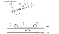
- FIG. 10 is a schematic view showing the cross section around the aluminum foil heater 43 constituting the partition plate 8 of the refrigerator 100 according to the first embodiment and the details of the cord-shaped heater 56.
- the upper side of FIG. 10 is a cross section around the aluminum foil heater 43, and the lower side of FIG. 10 is a schematic view showing details of the cord-shaped heater 56.
- the aluminum foil heater 43 is composed of a cord-shaped heater 56, an aluminum foil 54 for fixing the cord-shaped heater 56, and a double-sided tape 55, and is attached to the back side of the surface sheet metal 42 with the double-sided tape 55.
- the cord-shaped heater 56 is a cord in which a heating wire 59 such as a nichrome wire is wound around a core material 58 such as glass fiber at an equal pitch and is double-coated with insulating coating materials 60 and 61 such as polyvinyl chloride. It is a shaped heater.
- the cord-shaped heater 56 does not have to wind the heating wires 59 around the core material 58 at exactly equal pitches, and may wrap the heating wires 59 around the core material 58 at substantially equal pitches. Further, instead of the double-sided tape 55, the aluminum foil heater 43 may be glued and attached to the back side of the surface sheet metal 42.
- the cord-shaped heater 56 changes the winding pitch of the heating wire 59, for example, by changing the winding pitch of the upper part, the lower part, and the central part of the partition plate 8 to change the amount of heat generated at the portion of the partition plate 8. It is even better to use a variable pitch heater.
- the variable pitch heater requires a device capable of changing the speed at which the core wire is sent in manufacturing, and the manufacturing time is long, so that the cost is high. Therefore, it is better to decide whether or not to mount the variable pitch heater in consideration of cost performance.
- FIG. 11 is a view of the refrigerator 100 left door 6 and the partition plate 8 of the refrigerator 100 according to the first embodiment as viewed from the inside of the refrigerator.
- FIG. 12 is an enlarged view of a portion A in FIG.
- FIG. 13 is an enlarged view of a portion B of FIG.
- the partition plate 8 is attached to the double door with the upper hinge member 49 provided on the upper part of the partition plate 8 and the lower hinge provided on the lower part of the partition plate 8.
- the member 51 is fixed to the inner plate 87, which is the inner surface of the double door, with screws 46 so that the centers of the vertical rotation shafts 66, that is, the centers of the shaft shape portions 78 and 82 coincide with each other.
- the upper hinge member 49 and the lower hinge member 51 of the partition plate 8 are fixed to the inner plate 87 of the left door 6 of the refrigerator compartment with screws 46, respectively. Therefore, the partition plate 8 is adapted to rotate around the shaft-shaped portions 78 and 82.
- the main body 8a of the partition plate 8 is a portion that is not fixed to the inner plate 87 of the left door 6 of the refrigerator compartment. Then, the main body 8a of the partition plate 8 is attached to the upper hinge member 49 and the lower hinge member 51 in a state where the upper hinge member 49 and the lower hinge member 51 are fixed to the inner plate 87 of the refrigerating chamber left door 6. On the other hand, it is possible to move in the vertical direction.
- the upper hinge member 49 and the lower hinge member 51 are provided with arms 77 and 81 so as to extend from the inner plate 87 side of the refrigerating chamber left door 6 to the upper cover member 48 and the lower cover member 50 side.
- Cylindrical shaft-shaped portions 78 and 82 are provided at the ends of the arm portions 77 and 81, respectively.
- the shaft-shaped portion 78 extends downward
- the shaft-shaped portion 82 extends upward. Then, they are fitted with the tubular tube receiving shape portions 79 and 83 formed on the upper and lower sides of the resin member 53 on the back surface side of the partition plate 8, respectively.
- FIGS. 12 and 13 the portion of the shaft shape portions 78 and 82 that wraps with the cylinder receiving shape portions 79 and 83 is indicated by a broken line. Further, clearances 80 and 84 are formed between the arm portion 77 of the upper hinge member 49 and the back side resin member 53, and between the arm portion 81 of the lower hinge member 51 and the back surface side resin member 53, respectively. Has been done.
- FIG. 14 is a vertical cross-sectional view of the rotation axis 66 of FIG.
- FIG. 15 is an enlarged view of the vicinity of the lower hinge member 51 of the partition plate 8 when the left door 6 of the refrigerator 100 of the refrigerator 100 according to the first embodiment is open.
- FIG. 16 is an enlarged view of the vicinity of the lower hinge member 51 of the partition plate 8 while the left door 6 of the refrigerator 100 of the refrigerator 100 according to the first embodiment is being opened and closed.
- FIG. 17 is an enlarged view of the vicinity of the lower hinge member 51 of the partition plate 8 in the closed state of the left door 6 of the refrigerator 100 of the refrigerator 100 according to the first embodiment.
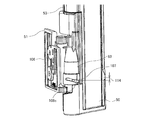
- the lower hinge member 51 is fixed to the inner plate 87 with screws 46 so that the fixing surface 106 thereof faces the inner plate 87 of the left door 6 of the refrigerator compartment. ing.
- the shaft-shaped portion 82 of the lower hinge member 51 is provided with a pin 107 projecting outward in the radial direction thereof.
- a spring 102 is housed inside the shaft-shaped portion 82 of the lower hinge member 51.
- the spring 102 is covered with a cylinder receiving shape portion 83 provided under the resin member 53 on the back surface side. Therefore, in the partition plate 8, the main body 8a is pushed upward by the reaction force of the spring 102. Then, the clearance 80 between the arm portion 77 of the upper hinge member 49 and the back side resin member 53 and the clearance 84 between the arm portion 81 of the lower hinge member 51 and the back side resin member 53 are narrowed by that amount. Only the upper end surface of the main body 8a, that is, the upper end surface 72 of the partition plate 8 moves upward.
- the guide groove 108 in which the pin 107 is housed is spirally formed in the cylinder receiving shape portion 83 so that the partition plate 8 can move up and down in the rotation axis 66 direction by rotating.
- the guide groove 108 does not have to be formed in a strictly spiral shape.
- the guide groove 108 is composed of a first groove 108a, a second groove 108b, and a third groove 108c.
- the first groove 108a is formed at a position where the pin 107 is accommodated when the left door 6 of the refrigerating chamber is open
- the second groove 108b is formed at a position where the pin 107 is accommodated when the left door 6 of the refrigerating chamber is closed.
- the first groove 108a is formed at a position higher than the second groove 108b. Therefore, a stroke 114, which is the difference in height between the first groove 108a and the second groove 108b, is formed between the upper end of the first groove 108a and the upper end of the first groove 108a in the vertical direction or the vertical direction. There is. Further, a third groove 108c is formed so as to be inclined between the first groove 108a and the second groove 108b, and the first groove 108a and the second groove 108b are connected by the third groove 108c. The third groove 108c becomes longer by the amount that the first groove 108a and the second groove 108b are shifted in the horizontal direction or the lateral direction.
- the guide groove 108 includes the first groove 108a and the second groove 108b, which are two grooves formed so as to be displaced in the vertical direction and the horizontal direction, and the third groove 108c, which is an inclined groove connecting the two grooves. It is composed of.
- the refrigerating chamber left door 6 is in the open state, and the pin 107 is in a position where it fits in the first groove 108a formed at the highest position in the guide groove 108.
- the left door 6 of the refrigerator compartment is in the process of being closed, and the pin 107 is located in the third groove 108c formed at a position lower than the first groove 108a and higher than the second groove 108b.
- the refrigerating chamber left door 6 is in the closed state, and the pin 107 is located in the second groove 108b formed at the lowest position in the guide groove 108.
- FIG. 18 is an enlarged view of the vicinity of the upper cover member 48 of the partition plate 8 showing a state in which the left door 6 of the refrigerator 100 of the refrigerator 100 according to the first embodiment is closed.
- FIG. 19 is a view of the upper cross section of the refrigerator 100 shown in FIG. 18 as viewed from below.
- FIG. 20 is a view showing a state in which the left door 6 of the refrigerator compartment is further closed as compared with FIG.
- FIG. 21 is a view showing a state in which the left door 6 of the refrigerator compartment is further closed as compared with FIG. Note that FIG. 21 shows a state in which the left door 6 of the refrigerator compartment is completely closed.
- a guide member 71 that guides the rotation of the main body 8a of the partition plate 8 when the left door 6 of the refrigerating chamber 6 is opened and closed is attached to the center of the lower front part of the ceiling 69 of the refrigerating chamber 1.
- the guide member 71 is provided with a guide protrusion 110 projecting downward.
- the guide protrusion 110 is interlocked with the opening and closing of the refrigerating room left door 6, and when the refrigerating room left door 6 is opened and closed, the refrigerating room left door 6 is in contact with the guide protrusion guide recess 109 formed in the upper cover member 48.
- the main body 8a of the partition plate 8 is rotated along the inner plate 87 of the partition plate 8.
- the cylinder receiving shape portion 83 moves with respect to the pin 107, and the position of the pin 107 is relatively in the order of the first groove 108a, the third groove 108c, and the second groove 108b in the guide groove 108, that is, the lower groove. Move in the direction of. Then, when the left door 6 of the refrigerator compartment is completely closed, the pin 107 is in a position where it fits in the second groove 108b, as shown in FIG. At this time, in the first groove 108a and the second groove 108b, the second groove 108b is at a lower position.
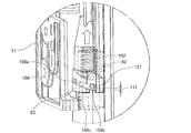
- FIG. 22 is an enlarged view of a portion C in FIG. In FIG. 22, some parts are shown by broken lines so that the internal structure of the lower hinge member 51 of the partition plate 8 can be seen.
- the necessity of the spring 102 housed inside the shaft-shaped portion 82 of the lower hinge member 51 will be described.
- the position of the left door 6 of the refrigerating room is lowered due to aged deterioration or food or the like is stored in the pocket 26 attached to the left door 6 of the refrigerating room. It goes down against the ceiling 69. Therefore, an upper gap is formed between the upper end surface 72 of the partition plate 8 and the flat lower surface 73 of the guide member 71 provided on the ceiling 69 of the refrigerating chamber 1.
- the position of the main body 8a of the partition plate 8 is changed by the spring 102 so that the main body 8a of the partition plate 8 can be moved upward.
- the upper end surface 72 of the partition plate 8 and the flat lower surface 73 of the guide member 71 provided on the ceiling 69 of the refrigerating chamber 1 come into contact with each other, and an upper gap is not formed.
- the guide groove 108 is formed in the cylinder receiving shape portion 83 provided in the lower part of the resin member 53 on the back side of the partition plate 8, and the pin 107 is in the middle of the first groove 108a to the third groove 108c.
- the pin 107 is located at the lower end of the guide groove 108 when it is between. Further, when the pin 107 crosses the middle of the third groove 108c, the pin 107 separates from the lower end of the guide groove 108.
- the pin 107 is in the second groove 108b, the pin 107 is located at a position having a slight stroke 111 from the lower end of the guide groove 108.
- the stroke 111 is a gap between the lower end of the pin 107 and the lower end of the second groove 108b.
- the spring 102 is extended so that the partition plate 8 is provided on the ceiling 69 of the refrigerating room 1 for this stroke 111 minutes.
- the guide member 71 can be brought into contact with the flat lower surface 73 so as to follow it. Further, the stroke 111 can absorb the variation in the mounting position of the partition plate 8 or the variation in the total length dimension of the partition plate 8. Therefore, regardless of the product variation, the upper end surface 72 of the partition plate 8 and the flat lower surface 73 of the guide member 71 provided on the ceiling 69 of the refrigerating chamber 1 can be stably brought into contact with each other.
- the stroke 111 is about 1 mm, which is smaller than the height difference between the first groove 108a and the second groove 108b, that is, the stroke 114 (see FIG. 16). By doing so, it is possible to suppress a collision of the refrigerator 100 with the housing 101 when the main body 8a of the partition plate 8 is rotated by opening and closing the left door 6 of the refrigerator compartment. Further, when the left door 6 of the refrigerating chamber 6 is opened and closed, the upper end surface 72 of the partition plate 8 can be brought into contact with the flat lower surface 73 of the guide member 71 provided on the ceiling 69 of the refrigerating chamber 1.
- the energization rate calculation formula determined in advance by a test or the like is programmed in the control device 29.
- the energization rate is defined by changing the voltage applied to the aluminum foil heater 43 over time, for example, energizing for 5 seconds within a predetermined time of 10 seconds and not energizing the remaining 5 seconds. In this case, the energization rate is 50%.
- the energization rate of the aluminum foil heater 43 is calculated by the control device 29 according to the outside air temperature, the outside air humidity, and the refrigerating room temperature, and changes according to the surrounding environment.
- the control device 29 calculates the energization rate calculation formula according to the outside air temperature, the outside air humidity, and the refrigerating room temperature detected by the outside air temperature sensor 9, the outside air humidity sensor 10, and the refrigerating room temperature sensor 32. Then, the energization rate of the aluminum foil heater 43 is determined.
- the determined energization rate is the energization rate at which dew does not adhere to the surface of the partition plate 8, the periphery of the refrigerating room left door 6 and the refrigerating room right door 7, or the gaskets 62, 64 and the gasket fins 63, 65, 75, 76. That is, it is an energization rate that improves the dew resistance and prevents dew condensation.
- the energization rate calculated from the energization rate calculation formula is such that the higher the outside air temperature and the outside air humidity, the higher the energization rate, and the lower the temperature of the refrigerating chamber 1, the higher the energization rate. Then, the control device 29 energizes the aluminum foil heater 43 at the energization rate determined by calculation. Therefore, if the outside air temperature and the outside air humidity are low and the refrigerating room temperature is high, the energization rate can be reduced, and the energy efficiency can be improved.
- FIG. 23 is a cross-sectional view taken along the line DD of FIG.
- FIG. 24 is a cross-sectional arrow view at the same position as FIG. 23 of the conventional refrigerator.
- the temperature of the gasket fins 63 and 65 is higher. It depends on the temperature of the gap 67.
- the upper end surface 72 of the partition plate 8 is provided on the ceiling 69 of the refrigerating chamber 1 by the reaction force 112 of the spring 102. It comes into contact with the flat lower surface 73 of the guide member 71. Then, the upper end surface 72 of the partition plate 8 comes into contact with the flat lower surface 73 of the guide member 71 provided on the ceiling 69 of the refrigerating chamber 1, so that the upper gap 67 is eliminated. Therefore, it is possible to prevent cold air from directly hitting the back surfaces of the gasket fins 63 and 65, and it is possible to raise the surface temperature of the gasket fins 63 and 65. Can be done and energy efficiency can be improved.
- the configuration of the partition plate 8, the method of energizing the aluminum foil heater 43, the energization rate calculation formula, and the like are not limited to the above contents.
- the partition plate 8 may be configured without the surface frame type resin member 44.
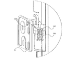
- FIG. 25 is an enlarged perspective view of the periphery of the upper hinge member 49 according to the modified example of the refrigerator 100 according to the first embodiment. In FIG. 25, some parts are shown by broken lines so that the internal structure of the upper hinge member 49 of the partition plate 8 can be seen.
- a mechanism having a pin 107 and a guide groove 108 is provided, but the present invention is not limited thereto.
- a mechanism having a spring 102, a pin 107, and a guide groove 108 may be provided on the upper part of the partition plate 8 as shown in FIG. , The same effect can be obtained by doing so.
- the refrigerator 100 has an outer shell, a housing 101 having a refrigerating chamber 1 inside, and a housing 101 provided on the front surface of the housing 101 to open and close the front opening of the refrigerating chamber 1.
- a partition plate 8 that is rotatably attached to one of the left and right double doors and one of the left and right double doors to prevent outside air from entering the refrigerator compartment 1, and the lower front part of the ceiling 69 of the refrigerator compartment 1.
- the guide member 71 provided in the above is provided.
- the partition plate 8 is provided on the upper and lower sides and is supported by the upper hinge member 49 and the lower hinge member 51 fixed to the inner surface of the double door, and the upper hinge member 49 and the lower hinge member 51, and the partition plate 8 is supported.
- a main body portion 8a that is guided by a guide member 71 and rotates when the double door is opened and closed.
- the main body 8a moves upward as compared with the open door, and the upper end surface of the main body 8a is moved upward.
- 72 is in contact with the lower surface 73 of the guide member 71.
- the main body 8a moves upward as compared with the state where the double door is open. Therefore, since the upper end surface 72 of the main body 8a is in contact with the lower surface 73 of the guide member 71, the upper end surface 72 of the partition plate 8 and the upper front surface of the refrigerator compartment 1 are in a state where the double door is closed. The gap between the opening and the opening can be reduced. Further, since the ball casters and the guide rails are not required, it is possible to suppress the deterioration of usability. Further, packing or the like is not required on the upper end surface 72 of the partition plate 8, and deterioration of the operability of the partition plate 8 can be suppressed.
- the space between the upper end surface 72 of the partition plate 8 and the lower surface 73 of the guide member 71 can be closed, it is possible to prevent the gap and prevent cold air from directly hitting the back surfaces of the gasket fins 63 and 65.
- the surface temperature of the gasket fins 63 and 65 can be raised. Therefore, the energization rate, which is higher than necessary, can be lowered, and the energy efficiency can be improved.
- the spring 102 is housed inside the shaft shape portion 82, and the spring 102 is covered with the cylinder receiving shape portion 83. Then, when closing the double door to which the partition plate 8 is attached, the pin 107 moves lower in the guide groove 108 as it rotates around the shaft-shaped portion 82, and the reaction force of the spring 102 causes the main body. The upper end surface 72 of the portion 8a moves upward.
- the upper end surface 72 of the partition plate 8 and the flat lower surface 73 of the guide member 71 provided on the ceiling 69 of the refrigerating chamber 1 are stably pressed regardless of the product variation. Can be touched.
- Embodiment 2 Hereinafter, the second embodiment will be described, but the description of the parts overlapping with the first embodiment will be omitted, and the same parts or the corresponding parts as those of the first embodiment will be designated by the same reference numerals.
- FIG. 26 is a vertical sectional view of the refrigerator 100 according to the second embodiment. Note that FIG. 26 is a cross-sectional arrow view at the same position as FIG. 23 of the first embodiment.
- the pin 107 is not provided in the shaft shape portion 82 of the lower hinge member 51, and the cylinder receiving shape portion 83 provided in the lower part of the back surface side resin member 53.
- the guide groove 108 is not formed in the.
- the magnet 113 is provided inside the guide member 71. Further, a screw 46 for fixing the upper cover member 48 is arranged on the upper end surface 72 of the partition plate 8. Then, the screw 46 arranged on the upper end surface 72 of the partition plate 8 is attracted by the magnetic force of the magnet 113 provided inside the guide member 71, and the main body portion 8a of the partition plate 8 is moved upward. By doing so, when the left door 6 of the refrigerating chamber is closed, the upper end surface 72 of the partition plate 8 and the flat lower surface 73 of the guide member 71 provided on the ceiling 69 of the refrigerating chamber 1 are brought into contact with each other.
- the clearances 80 and 84 between the arms 77 and 81 of the upper hinge member 49 and the lower hinge member 51 and the back resin member 53 shown in FIGS. 12 and 13 are set as play dimensions.
- the resin member 53 on the back side of the partition plate 8 moves downward due to gravity, and the lower end surface of the cylinder receiving shape portion 83 provided under the resin member 53 on the back side of the partition plate 8 is provided. Is in a state of being on the arm 81 of the lower hinge member 51.
- FIG. 27 is an enlarged perspective view of the upper part of the partition plate 8 according to the modified example of the refrigerator 100 according to the second embodiment.
- a bent portion 42a is formed on the upper end surface 72 of the partition plate 8 instead of the screw 46, and the bent portion 42a is fixed to the upper end surface 72 of the partition plate 8. .. Then, the bent portion 42a of the surface sheet metal 42 may be attracted by the magnetic force of the magnet 113 inside the guide member 71.
- the upper end portion of the surface sheet metal 42 is a guide protrusion guide recess 109 of the upper cover member 48 in which the upper end portion of the surface sheet metal 42 is rotated by the guide protrusion 110 to some extent from the surface side of the upper end surface 72 of the partition plate 8. It is formed by bending it to the front.
- the main body 8a of the partition plate 8 rotates according to the opening and closing of the left door 6 of the refrigerating chamber, and when the left door 6 of the refrigerating chamber is closed, the upper end surface 72 of the partition plate 8 is formed.
- the upper gap 67 is eliminated by contacting the flat lower surface 73 of the guide member 71 provided on the ceiling 69 of the refrigerator compartment 1. Therefore, it is possible to prevent cold air from directly hitting the back surfaces of the gasket fins 63 and 65, and it is possible to raise the surface temperature of the gasket fins 63 and 65. Can be done and energy efficiency can be improved.
- the screw 46 is arranged on the upper end surface 72 of the main body 8a, and the magnet 113 is provided inside the guide member 71.
- the screw 46 is attracted to the magnet 113 as compared with the open door, and the upper end surface 72 of the main body 8a Is in contact with the lower surface 73 of the guide member 71.
- the main body 8a has a metal surface sheet metal 42 located on the surface side, and the surface sheet metal 42 has a bent portion 42a whose upper end is bent.
- a bent portion 42a of the surface sheet metal 42 is arranged on the upper end surface 72 of the main body portion 8a, and a magnet 113 is provided inside the guide member 71.
- the screw 46 is attracted to the magnet 113 as compared with the state where the double door is open.
- the upper end surface 72 of the main body 8a is in contact with the lower surface 73 of the guide member 71.
- the bent portion 42a is attracted to the magnet 113 as compared with the open state of the double door, and the upper end surface of the main body 8a is attracted.
- 72 is in contact with the lower surface 73 of the guide member 71. Therefore, when the double door is closed, the gap between the upper end surface 72 of the partition plate 8 and the upper front opening of the refrigerator compartment 1 can be reduced.
- the ball casters and the guide rails are not required, it is possible to suppress the deterioration of usability. Further, packing or the like is not required on the upper end surface 72 of the partition plate 8, and deterioration of the operability of the partition plate 8 can be suppressed. Further, since the space between the upper end surface 72 of the partition plate 8 and the lower surface 73 of the guide member 71 can be closed, it is possible to prevent the gap and prevent cold air from directly hitting the back surfaces of the gasket fins 63 and 65. The surface temperature of the gasket fins 63 and 65 can be raised. Therefore, the energization rate, which is higher than necessary, can be lowered, and the energy efficiency can be improved.
- Embodiment 3 Hereinafter, the third embodiment will be described, but the description of the parts overlapping with the first embodiment will be omitted, and the same parts or the corresponding parts as those of the first embodiment will be designated by the same reference numerals.
- the hinge structure of the refrigerator compartment door has been strengthened to the extent that the position of the refrigerator compartment left door 6 does not move even if food or the like is stored in the pocket 26 attached to the refrigerator compartment left door 6 due to aged deterioration.
- the distance between the upper end surface 72 of the partition plate 8 and the ceiling 69 of the refrigerator compartment 1 is constant. Therefore, by strengthening the hinge structure of the refrigerator compartment door to the extent that the position of the refrigerator compartment left door 6 does not move down, a push-up structure by the reaction force of the spring 102 or a pull-in structure by the magnetic force of the magnet 113 becomes unnecessary, and the cost is reduced. Can be reduced.
- the pin 107 moves in the guide groove 108 to cause the refrigerating chamber left door 6 to move.
- the main body 8a of the partition plate 8 moves up and down according to the opening and closing.
- a member that assists the vertical movement of a part of the partition plate 8 such as the spring 102 described in the first embodiment and the magnet 113 described in the second embodiment (hereinafter, vertical movement). It does not have an auxiliary member). Therefore, when the left door 6 of the refrigerator compartment is opened, the main body 8a of the partition plate 8 rotates while the pin 107 and the guide groove 108 are in contact with each other due to its own weight.
- a mechanism having a pin 107 and a guide groove 108 may be provided in the upper part of the partition plate 8 in addition to the lower part of the partition plate 8 or in place of the lower part of the partition plate 8, and the same effect can be obtained by doing so. Be done.
Landscapes
- Engineering & Computer Science (AREA)
- Chemical & Material Sciences (AREA)
- Combustion & Propulsion (AREA)
- Physics & Mathematics (AREA)
- Mechanical Engineering (AREA)
- Thermal Sciences (AREA)
- General Engineering & Computer Science (AREA)
- Refrigerator Housings (AREA)
Priority Applications (2)
| Application Number | Priority Date | Filing Date | Title |
|---|---|---|---|
| JP2022507117A JP7275378B2 (ja) | 2020-03-12 | 2020-03-12 | 冷蔵庫 |
| PCT/JP2020/010838 WO2021181609A1 (ja) | 2020-03-12 | 2020-03-12 | 冷蔵庫 |
Applications Claiming Priority (1)
| Application Number | Priority Date | Filing Date | Title |
|---|---|---|---|
| PCT/JP2020/010838 WO2021181609A1 (ja) | 2020-03-12 | 2020-03-12 | 冷蔵庫 |
Publications (1)
| Publication Number | Publication Date |
|---|---|
| WO2021181609A1 true WO2021181609A1 (ja) | 2021-09-16 |
Family
ID=77670553
Family Applications (1)
| Application Number | Title | Priority Date | Filing Date |
|---|---|---|---|
| PCT/JP2020/010838 Ceased WO2021181609A1 (ja) | 2020-03-12 | 2020-03-12 | 冷蔵庫 |
Country Status (2)
| Country | Link |
|---|---|
| JP (1) | JP7275378B2 (https=) |
| WO (1) | WO2021181609A1 (https=) |
Citations (6)
| Publication number | Priority date | Publication date | Assignee | Title |
|---|---|---|---|---|
| JP2000161841A (ja) * | 1998-11-30 | 2000-06-16 | Mitsubishi Electric Corp | 冷蔵庫 |
| US20140159560A1 (en) * | 2012-12-10 | 2014-06-12 | Lg Electronics Inc. | Refrigerator |
| KR20150003642A (ko) * | 2013-07-01 | 2015-01-09 | 주식회사 대유위니아 | 양문형 냉장고의 실링장치 |
| JP2018112385A (ja) * | 2017-01-06 | 2018-07-19 | パナソニック株式会社 | 冷蔵庫 |
| WO2020012629A1 (ja) * | 2018-07-13 | 2020-01-16 | 三菱電機株式会社 | 冷蔵庫 |
| WO2020012526A1 (ja) * | 2018-07-09 | 2020-01-16 | 三菱電機株式会社 | 冷蔵庫 |
-
2020
- 2020-03-12 JP JP2022507117A patent/JP7275378B2/ja active Active
- 2020-03-12 WO PCT/JP2020/010838 patent/WO2021181609A1/ja not_active Ceased
Patent Citations (6)
| Publication number | Priority date | Publication date | Assignee | Title |
|---|---|---|---|---|
| JP2000161841A (ja) * | 1998-11-30 | 2000-06-16 | Mitsubishi Electric Corp | 冷蔵庫 |
| US20140159560A1 (en) * | 2012-12-10 | 2014-06-12 | Lg Electronics Inc. | Refrigerator |
| KR20150003642A (ko) * | 2013-07-01 | 2015-01-09 | 주식회사 대유위니아 | 양문형 냉장고의 실링장치 |
| JP2018112385A (ja) * | 2017-01-06 | 2018-07-19 | パナソニック株式会社 | 冷蔵庫 |
| WO2020012526A1 (ja) * | 2018-07-09 | 2020-01-16 | 三菱電機株式会社 | 冷蔵庫 |
| WO2020012629A1 (ja) * | 2018-07-13 | 2020-01-16 | 三菱電機株式会社 | 冷蔵庫 |
Also Published As
| Publication number | Publication date |
|---|---|
| JP7275378B2 (ja) | 2023-05-17 |
| JPWO2021181609A1 (https=) | 2021-09-16 |
Similar Documents
| Publication | Publication Date | Title |
|---|---|---|
| US20120047922A1 (en) | Direct cooling refrigerator and control method thereof | |
| AU2022200857B2 (en) | Refrigerator | |
| CN102679663A (zh) | 冰箱 | |
| WO2006049355A9 (en) | Defrost operating method for refrigerator | |
| US11022329B1 (en) | Humidity control system | |
| US11549741B2 (en) | Apparatus for sensing and removing dew on refrigerator and controlling method thereof | |
| JP2017146094A (ja) | 遮蔽装置およびそれを有する冷蔵庫 | |
| KR20160001389A (ko) | 냉장고 및 그 제어 방법 | |
| JP2013224777A (ja) | 冷蔵庫 | |
| JP7275378B2 (ja) | 冷蔵庫 | |
| JP7066058B2 (ja) | 冷蔵庫 | |
| JP7389615B2 (ja) | 冷蔵庫 | |
| JP6214486B2 (ja) | 冷蔵庫 | |
| CN219328234U (zh) | 冰箱 | |
| WO2020250421A1 (ja) | 冷蔵庫 | |
| JP2016161231A (ja) | 冷蔵庫 | |
| JP6987297B2 (ja) | 冷蔵庫 | |
| JP6956900B2 (ja) | 冷蔵庫 | |
| JP6694538B2 (ja) | 冷蔵庫 | |
| JP7275377B2 (ja) | 冷蔵庫 | |
| CN223106351U (zh) | 存储设备 | |
| HK40064783A (en) | Refrigerator | |
| JP7312148B2 (ja) | 冷蔵庫 | |
| CN1888778B (zh) | 泡菜冰箱的内部机壳增强结构 | |
| HK40064783B (en) | Refrigerator |
Legal Events
| Date | Code | Title | Description |
|---|---|---|---|
| 121 | Ep: the epo has been informed by wipo that ep was designated in this application |
Ref document number: 20924248 Country of ref document: EP Kind code of ref document: A1 |
|
| ENP | Entry into the national phase |
Ref document number: 2022507117 Country of ref document: JP Kind code of ref document: A |
|
| NENP | Non-entry into the national phase |
Ref country code: DE |
|
| 122 | Ep: pct application non-entry in european phase |
Ref document number: 20924248 Country of ref document: EP Kind code of ref document: A1 |