WO2021181570A1 - ガス軟窒化処理部品及びその製造方法 - Google Patents
ガス軟窒化処理部品及びその製造方法 Download PDFInfo
- Publication number
- WO2021181570A1 WO2021181570A1 PCT/JP2020/010585 JP2020010585W WO2021181570A1 WO 2021181570 A1 WO2021181570 A1 WO 2021181570A1 JP 2020010585 W JP2020010585 W JP 2020010585W WO 2021181570 A1 WO2021181570 A1 WO 2021181570A1
- Authority
- WO
- WIPO (PCT)
- Prior art keywords
- gas
- less
- compound layer
- steel
- nitriding
- Prior art date
- Legal status (The legal status is an assumption and is not a legal conclusion. Google has not performed a legal analysis and makes no representation as to the accuracy of the status listed.)
- Ceased
Links
Images


Classifications
-
- C—CHEMISTRY; METALLURGY
- C22—METALLURGY; FERROUS OR NON-FERROUS ALLOYS; TREATMENT OF ALLOYS OR NON-FERROUS METALS
- C22C—ALLOYS
- C22C38/00—Ferrous alloys, e.g. steel alloys
- C22C38/02—Ferrous alloys, e.g. steel alloys containing silicon
-
- C—CHEMISTRY; METALLURGY
- C21—METALLURGY OF IRON
- C21D—MODIFYING THE PHYSICAL STRUCTURE OF FERROUS METALS; GENERAL DEVICES FOR HEAT TREATMENT OF FERROUS OR NON-FERROUS METALS OR ALLOYS; MAKING METAL MALLEABLE, e.g. BY DECARBURISATION OR TEMPERING
- C21D1/00—General methods or devices for heat treatment, e.g. annealing, hardening, quenching or tempering
- C21D1/06—Surface hardening
-
- C—CHEMISTRY; METALLURGY
- C21—METALLURGY OF IRON
- C21D—MODIFYING THE PHYSICAL STRUCTURE OF FERROUS METALS; GENERAL DEVICES FOR HEAT TREATMENT OF FERROUS OR NON-FERROUS METALS OR ALLOYS; MAKING METAL MALLEABLE, e.g. BY DECARBURISATION OR TEMPERING
- C21D1/00—General methods or devices for heat treatment, e.g. annealing, hardening, quenching or tempering
- C21D1/74—Methods of treatment in inert gas, controlled atmosphere, vacuum or pulverulent material
- C21D1/76—Adjusting the composition of the atmosphere
-
- C—CHEMISTRY; METALLURGY
- C21—METALLURGY OF IRON
- C21D—MODIFYING THE PHYSICAL STRUCTURE OF FERROUS METALS; GENERAL DEVICES FOR HEAT TREATMENT OF FERROUS OR NON-FERROUS METALS OR ALLOYS; MAKING METAL MALLEABLE, e.g. BY DECARBURISATION OR TEMPERING
- C21D6/00—Heat treatment of ferrous alloys
-
- C—CHEMISTRY; METALLURGY
- C21—METALLURGY OF IRON
- C21D—MODIFYING THE PHYSICAL STRUCTURE OF FERROUS METALS; GENERAL DEVICES FOR HEAT TREATMENT OF FERROUS OR NON-FERROUS METALS OR ALLOYS; MAKING METAL MALLEABLE, e.g. BY DECARBURISATION OR TEMPERING
- C21D9/00—Heat treatment, e.g. annealing, hardening, quenching or tempering, adapted for particular articles; Furnaces therefor
- C21D9/30—Heat treatment, e.g. annealing, hardening, quenching or tempering, adapted for particular articles; Furnaces therefor for crankshafts; for camshafts
-
- C—CHEMISTRY; METALLURGY
- C22—METALLURGY; FERROUS OR NON-FERROUS ALLOYS; TREATMENT OF ALLOYS OR NON-FERROUS METALS
- C22C—ALLOYS
- C22C38/00—Ferrous alloys, e.g. steel alloys
- C22C38/002—Ferrous alloys, e.g. steel alloys containing In, Mg, or other elements not provided for in one single group C22C38/001 - C22C38/60
-
- C—CHEMISTRY; METALLURGY
- C22—METALLURGY; FERROUS OR NON-FERROUS ALLOYS; TREATMENT OF ALLOYS OR NON-FERROUS METALS
- C22C—ALLOYS
- C22C38/00—Ferrous alloys, e.g. steel alloys
- C22C38/005—Ferrous alloys, e.g. steel alloys containing rare earths, i.e. Sc, Y, Lanthanides
-
- C—CHEMISTRY; METALLURGY
- C22—METALLURGY; FERROUS OR NON-FERROUS ALLOYS; TREATMENT OF ALLOYS OR NON-FERROUS METALS
- C22C—ALLOYS
- C22C38/00—Ferrous alloys, e.g. steel alloys
- C22C38/04—Ferrous alloys, e.g. steel alloys containing manganese
-
- C—CHEMISTRY; METALLURGY
- C22—METALLURGY; FERROUS OR NON-FERROUS ALLOYS; TREATMENT OF ALLOYS OR NON-FERROUS METALS
- C22C—ALLOYS
- C22C38/00—Ferrous alloys, e.g. steel alloys
- C22C38/18—Ferrous alloys, e.g. steel alloys containing chromium
- C22C38/20—Ferrous alloys, e.g. steel alloys containing chromium with copper
-
- C—CHEMISTRY; METALLURGY
- C22—METALLURGY; FERROUS OR NON-FERROUS ALLOYS; TREATMENT OF ALLOYS OR NON-FERROUS METALS
- C22C—ALLOYS
- C22C38/00—Ferrous alloys, e.g. steel alloys
- C22C38/18—Ferrous alloys, e.g. steel alloys containing chromium
- C22C38/22—Ferrous alloys, e.g. steel alloys containing chromium with molybdenum or tungsten
-
- C—CHEMISTRY; METALLURGY
- C22—METALLURGY; FERROUS OR NON-FERROUS ALLOYS; TREATMENT OF ALLOYS OR NON-FERROUS METALS
- C22C—ALLOYS
- C22C38/00—Ferrous alloys, e.g. steel alloys
- C22C38/18—Ferrous alloys, e.g. steel alloys containing chromium
- C22C38/24—Ferrous alloys, e.g. steel alloys containing chromium with vanadium
-
- C—CHEMISTRY; METALLURGY
- C22—METALLURGY; FERROUS OR NON-FERROUS ALLOYS; TREATMENT OF ALLOYS OR NON-FERROUS METALS
- C22C—ALLOYS
- C22C38/00—Ferrous alloys, e.g. steel alloys
- C22C38/18—Ferrous alloys, e.g. steel alloys containing chromium
- C22C38/26—Ferrous alloys, e.g. steel alloys containing chromium with niobium or tantalum
-
- C—CHEMISTRY; METALLURGY
- C22—METALLURGY; FERROUS OR NON-FERROUS ALLOYS; TREATMENT OF ALLOYS OR NON-FERROUS METALS
- C22C—ALLOYS
- C22C38/00—Ferrous alloys, e.g. steel alloys
- C22C38/18—Ferrous alloys, e.g. steel alloys containing chromium
- C22C38/28—Ferrous alloys, e.g. steel alloys containing chromium with titanium or zirconium
-
- C—CHEMISTRY; METALLURGY
- C22—METALLURGY; FERROUS OR NON-FERROUS ALLOYS; TREATMENT OF ALLOYS OR NON-FERROUS METALS
- C22C—ALLOYS
- C22C38/00—Ferrous alloys, e.g. steel alloys
- C22C38/18—Ferrous alloys, e.g. steel alloys containing chromium
- C22C38/30—Ferrous alloys, e.g. steel alloys containing chromium with cobalt
-
- C—CHEMISTRY; METALLURGY
- C22—METALLURGY; FERROUS OR NON-FERROUS ALLOYS; TREATMENT OF ALLOYS OR NON-FERROUS METALS
- C22C—ALLOYS
- C22C38/00—Ferrous alloys, e.g. steel alloys
- C22C38/18—Ferrous alloys, e.g. steel alloys containing chromium
- C22C38/32—Ferrous alloys, e.g. steel alloys containing chromium with boron
-
- C—CHEMISTRY; METALLURGY
- C22—METALLURGY; FERROUS OR NON-FERROUS ALLOYS; TREATMENT OF ALLOYS OR NON-FERROUS METALS
- C22C—ALLOYS
- C22C38/00—Ferrous alloys, e.g. steel alloys
- C22C38/18—Ferrous alloys, e.g. steel alloys containing chromium
- C22C38/38—Ferrous alloys, e.g. steel alloys containing chromium with more than 1.5% by weight of manganese
-
- C—CHEMISTRY; METALLURGY
- C22—METALLURGY; FERROUS OR NON-FERROUS ALLOYS; TREATMENT OF ALLOYS OR NON-FERROUS METALS
- C22C—ALLOYS
- C22C38/00—Ferrous alloys, e.g. steel alloys
- C22C38/18—Ferrous alloys, e.g. steel alloys containing chromium
- C22C38/40—Ferrous alloys, e.g. steel alloys containing chromium with nickel
- C22C38/42—Ferrous alloys, e.g. steel alloys containing chromium with nickel with copper
-
- C—CHEMISTRY; METALLURGY
- C22—METALLURGY; FERROUS OR NON-FERROUS ALLOYS; TREATMENT OF ALLOYS OR NON-FERROUS METALS
- C22C—ALLOYS
- C22C38/00—Ferrous alloys, e.g. steel alloys
- C22C38/18—Ferrous alloys, e.g. steel alloys containing chromium
- C22C38/40—Ferrous alloys, e.g. steel alloys containing chromium with nickel
- C22C38/46—Ferrous alloys, e.g. steel alloys containing chromium with nickel with vanadium
-
- C—CHEMISTRY; METALLURGY
- C23—COATING METALLIC MATERIAL; COATING MATERIAL WITH METALLIC MATERIAL; CHEMICAL SURFACE TREATMENT; DIFFUSION TREATMENT OF METALLIC MATERIAL; COATING BY VACUUM EVAPORATION, BY SPUTTERING, BY ION IMPLANTATION OR BY CHEMICAL VAPOUR DEPOSITION, IN GENERAL; INHIBITING CORROSION OF METALLIC MATERIAL OR INCRUSTATION IN GENERAL
- C23C—COATING METALLIC MATERIAL; COATING MATERIAL WITH METALLIC MATERIAL; SURFACE TREATMENT OF METALLIC MATERIAL BY DIFFUSION INTO THE SURFACE, BY CHEMICAL CONVERSION OR SUBSTITUTION; COATING BY VACUUM EVAPORATION, BY SPUTTERING, BY ION IMPLANTATION OR BY CHEMICAL VAPOUR DEPOSITION, IN GENERAL
- C23C8/00—Solid state diffusion of only non-metal elements into metallic material surfaces; Chemical surface treatment of metallic material by reaction of the surface with a reactive gas, leaving reaction products of surface material in the coating, e.g. conversion coatings, passivation of metals
- C23C8/02—Pretreatment of the material to be coated
-
- C—CHEMISTRY; METALLURGY
- C23—COATING METALLIC MATERIAL; COATING MATERIAL WITH METALLIC MATERIAL; CHEMICAL SURFACE TREATMENT; DIFFUSION TREATMENT OF METALLIC MATERIAL; COATING BY VACUUM EVAPORATION, BY SPUTTERING, BY ION IMPLANTATION OR BY CHEMICAL VAPOUR DEPOSITION, IN GENERAL; INHIBITING CORROSION OF METALLIC MATERIAL OR INCRUSTATION IN GENERAL
- C23C—COATING METALLIC MATERIAL; COATING MATERIAL WITH METALLIC MATERIAL; SURFACE TREATMENT OF METALLIC MATERIAL BY DIFFUSION INTO THE SURFACE, BY CHEMICAL CONVERSION OR SUBSTITUTION; COATING BY VACUUM EVAPORATION, BY SPUTTERING, BY ION IMPLANTATION OR BY CHEMICAL VAPOUR DEPOSITION, IN GENERAL
- C23C8/00—Solid state diffusion of only non-metal elements into metallic material surfaces; Chemical surface treatment of metallic material by reaction of the surface with a reactive gas, leaving reaction products of surface material in the coating, e.g. conversion coatings, passivation of metals
- C23C8/06—Solid state diffusion of only non-metal elements into metallic material surfaces; Chemical surface treatment of metallic material by reaction of the surface with a reactive gas, leaving reaction products of surface material in the coating, e.g. conversion coatings, passivation of metals using gases
- C23C8/08—Solid state diffusion of only non-metal elements into metallic material surfaces; Chemical surface treatment of metallic material by reaction of the surface with a reactive gas, leaving reaction products of surface material in the coating, e.g. conversion coatings, passivation of metals using gases only one element being applied
- C23C8/24—Nitriding
- C23C8/26—Nitriding of ferrous surfaces
-
- C—CHEMISTRY; METALLURGY
- C23—COATING METALLIC MATERIAL; COATING MATERIAL WITH METALLIC MATERIAL; CHEMICAL SURFACE TREATMENT; DIFFUSION TREATMENT OF METALLIC MATERIAL; COATING BY VACUUM EVAPORATION, BY SPUTTERING, BY ION IMPLANTATION OR BY CHEMICAL VAPOUR DEPOSITION, IN GENERAL; INHIBITING CORROSION OF METALLIC MATERIAL OR INCRUSTATION IN GENERAL
- C23C—COATING METALLIC MATERIAL; COATING MATERIAL WITH METALLIC MATERIAL; SURFACE TREATMENT OF METALLIC MATERIAL BY DIFFUSION INTO THE SURFACE, BY CHEMICAL CONVERSION OR SUBSTITUTION; COATING BY VACUUM EVAPORATION, BY SPUTTERING, BY ION IMPLANTATION OR BY CHEMICAL VAPOUR DEPOSITION, IN GENERAL
- C23C8/00—Solid state diffusion of only non-metal elements into metallic material surfaces; Chemical surface treatment of metallic material by reaction of the surface with a reactive gas, leaving reaction products of surface material in the coating, e.g. conversion coatings, passivation of metals
- C23C8/80—After-treatment
Definitions
- the present invention relates to a steel part subjected to gas soft nitriding treatment and a method for manufacturing the same.
- Some steel parts used in automobiles and various industrial machines require surface fatigue strength.
- CVT pulleys and camshafts in transmissions are required to have abrasion resistance and bending fatigue strength, and gears are required to have fatigue characteristics such as surface fatigue strength and bending fatigue strength. It is said that improvement of surface hardness is effective for improving these characteristics. Therefore, nitriding and soft nitriding treatments are being applied to these steel parts.
- the nitriding treatment and the soft nitriding treatment have the advantages that high surface hardness can be obtained and heat treatment strain is small.
- Nitriding is a surface hardening heat treatment that allows nitrogen to penetrate the surface of steel
- soft nitriding is a surface hardening heat treatment that allows nitrogen and carbon to penetrate the surface of steel.
- the medium used for nitriding and soft nitriding includes gas, salt bath, plasma and the like. Gas nitriding and gas nitrocarburizing, which are excellent in productivity, are mainly applied to transmission parts of automobiles.
- the cured layer produced by gas nitriding and gas nitrocarburizing consists of a nitrogen diffusion layer (hereinafter, may be abbreviated as a diffusion layer) and a compound layer having a thickness of several to several tens of ⁇ m formed on the surface side of the diffusion layer. be.
- the diffusion layer is a layer cured by a solid solution strengthening mechanism by penetrating nitrogen and carbon, and a particle dispersion strengthening mechanism of nitride. It is known that improving the hardness and depth of the diffusion layer improves the bending fatigue strength and surface fatigue strength of parts. Many studies have been conducted on the improvement of the hardness and depth of the diffusion layer.
- the compound layer is mainly composed of iron nitrides of Fe 2 N to Fe 3 N ( ⁇ phase) and Fe 4 N ( ⁇ 'phase), and has extremely high hardness as compared with the matrix phase. Therefore, the compound layer is effective in improving the wear resistance.
- the ⁇ phase has a larger solid solution range of C and a higher growth rate than the ⁇ 'phase. For this reason, in soft nitriding in which a carburizing gas is mixed, a compound layer mainly composed of the ⁇ phase is likely to be formed. Therefore, soft nitriding can obtain a thick compound layer in a shorter time than nitriding, regardless of the steel type of the component. Therefore, soft nitriding has been used for a long time for the purpose of improving the wear resistance of parts.
- Patent Document 1 describes nitriding or nitriding or characterized in that the thickness of the ⁇ single-phase compound layer is 8 to 30 ⁇ m, the Vickers hardness is 680 HV or more, and the volume ratio of the voids in the compound layer is less than 10%. Soft nitride components are disclosed.
- Patent Document 2 the compound layer thickness after nitriding is 1 to 5 ⁇ m, the surface roughness after nitriding is Rz 1.6 or less, and the compound layer is ⁇ 'phase or ⁇ 'phase and ⁇ .
- Patent Document 3 discloses that a nitriding component is produced under nitriding potential control by adjusting the content of steel components, particularly C, Mn, Cr, V, and Mo, according to a target property. There is.
- Patent Document 4 describes a component having excellent rotational bending fatigue strength in addition to surface fatigue strength, which is made of a steel material having a predetermined chemical composition and contains iron, nitrogen and carbon formed on the surface of the steel material. It has a compound layer with a thickness of 3 ⁇ m or more and less than 20 ⁇ m, and the phase structure of the compound layer in the range from the surface to a depth of 5 ⁇ m contains ⁇ 'phase in an area ratio of 50% or more, and in a range from the surface to a depth of 3 ⁇ m.
- a nitriding component characterized in that the void area ratio is less than 1% and the compressive residual stress on the surface of the compound layer is 500 MPa or more is disclosed.
- Patent Document 5 describes that when low alloy steel is heated to 550 to 620 ° C. and gas nitrocarburizing treatment is performed with a treatment time A of 1.5 to 10 hours, the nitriding potential Kn X is 0.10 to 1.00. , The average value Kn Xave is 0.20 to 0.55, and after high Kn value processing with the processing time as X hours, the nitriding potential Kn Y is in the range of 0.01 to 0.20, and the average value.
- the void ratio in the outermost surface to the lowermost surface (the interface between the compound layer and the diffusion layer) of the compound layer is suppressed.
- the voids are often concentrated in the area from the surface of the steel to about 3 ⁇ m. If there are many voids in this region, good bending fatigue strength cannot be obtained.
- the pores of the compound layer were concentrated in the surface layer region of the component, and the volume fraction of the pores in this surface layer region exceeded 40%. rice field. Therefore, there is room for improvement in the technique of Patent Document 1 regarding the steel component for suppressing the void ratio at the surface to 3 ⁇ m and the nitriding control method.
- the nitrided part of Patent Document 2 has a very thin compound layer of at least 1 ⁇ m, and has a phase structure mainly composed of a ⁇ 'phase having a hardness lower than that of the ⁇ phase. Therefore, according to the technique of Patent Document 2, good wear resistance may not be obtained.
- the structure of the compound layer is mainly composed of the ⁇ 'phase having a low hardness.
- the nitriding potential is set to a value lower than usual. Therefore, it is considered that the nitrided parts of Patent Documents 3 to 5 have room for improvement in terms of wear resistance.
- An object of the present invention is to provide a part having excellent wear resistance as well as rotational bending fatigue strength and a method for manufacturing the same.
- the gist of the present invention is as follows.
- the gas nitrocarburizing component according to one aspect of the present invention includes a steel core portion, a compound layer, and a nitrogen diffusion layer existing between the steel core portion and the compound layer, and the steel.
- the composition of the core is C: 0.05% to 0.60%, Si: 0.05% to 1.50%, Mn: 0.20% to 2.50%, P: 0.
- the balance contains Fe and impurities, the content of C, Mn, Cr, V, Mo in the composition of the steel core portion satisfies the formula 1, and the thickness of the compound layer is 3 to 20 ⁇ m.
- the compound layer contains more than 50% of the ⁇ phase in terms of area ratio, the balance is the ⁇ 'phase, and the area ratio of the voids is less than 12% in the region from the surface of the compound layer to a depth of 3 ⁇ m. Is.
- the element symbol in the formula 1 indicates the content (mass%) of the element, and if it is not contained, 0 is substituted.
- the composition of the steel core portion is C: 0.05% to 0.60% and Si: 0.05% to 1 in mass%.
- Mn 0.20% to 2.50%, P: 0.025% or less
- S 0.050% or less
- Cr 0.50% to 2.50%
- V 0.05% ⁇ 1.30%
- Al 0.050% or less
- N 0.0250% or less
- Mo 0 to 1.50%
- Cu 0 to 1.00%
- W 0 to 0.50%
- Co 0 to 0.50%
- Nb 0 to 0.300%
- Ti 0 to 0.250%
- B 0 to 0.0100%
- Ca 0 to 0. It may contain 010%, Mg: 0 to 0.010%, and REM: 0 to 0.010%, with the balance consisting of Fe and impurities.
- the ⁇ phase in the compound layer may have an area ratio of 90% or less.
- the thickness of the compound layer may be 6 ⁇ m or more.
- the method for manufacturing a gas nitriding-treated part according to another aspect of the present invention is the method for manufacturing a gas nitriding-treated part according to any one of (1) to (5) above.
- the gas nitrocarburizing treatment comprises steps and, in which the gas containing at least one of CO 2 , CO and hydrocarbon gas is contained in a carburable gas input ratio represented by the formula 2 in an amount of 2% by volume or more and less than 10% by volume.
- the balance is maintained at a temperature of 550 ° C. or higher and 630 ° C. or lower for 1 hour or more and 7 hours or less.
- the required nitriding potential K N is within the range of 0.15 or more and 0.40 or less through the step of performing the gas soft nitriding treatment, and the average value K Nave of the nitriding potential K N is 0.18 or more and 0.30. Is less than.
- Carburizing gas input ratio (volume%) CO 2 , CO, total input flow rate of hydrocarbon gas (l / min) / total input flow rate of atmospheric gas (l / min) ⁇ 100 ... Equation 2
- K N (NH 3 partial pressure) / [(H 2 partial pressure) 3/2 ] (atm- 1 / 2 ) ⁇ ⁇ ⁇ Equation 3
- the present inventors focused on the morphology of the compound layer formed on the surface of the steel material by soft nitriding, and investigated the relationship between the morphology of the compound layer and the fatigue strength.
- the voids generated on the surface side of the compound layer can be suppressed by soft nitriding the steel material whose composition has been adjusted while controlling the nitriding potential in a constant atmosphere. Furthermore, it has been found that by setting the thickness of the compound layer within a certain range and the hardness of the compound layer to a certain value or more, a soft nitrided part having excellent wear resistance and rotational bending fatigue strength can be produced.
- the gas nitrocarburizing component 1 (hereinafter, may be simply referred to as “part”) according to the present embodiment is referred to as a steel core portion 11 (hereinafter, simply referred to as “steel”). There is), and a nitrogen diffusion layer 13 (hereinafter, may be simply referred to as a “diffusion layer”) existing between the compound layer 12 and the steel core portion 11 and the compound layer 12.
- a nitrogen diffusion layer 13 (hereinafter, may be simply referred to as a “diffusion layer”) existing between the compound layer 12 and the steel core portion 11 and the compound layer 12.
- C stabilizes the formation of the ⁇ phase. Therefore, C is an element effective for increasing the thickness of the compound layer after nitriding and the volume ratio of the ⁇ phase and enhancing the wear resistance of the component. In addition, C is an element necessary for ensuring the hardness of the core of the component. In order to obtain these effects, C needs to be 0.05% or more. On the other hand, if the C content exceeds 0.60%, the hardness of the steel bars and wires used as raw materials after hot forging becomes too high. Therefore, the machinability of the material is greatly reduced.
- the C content may be 0.08% or more, 0.10% or more, or 0.15% or more.
- the C content may be 0.55% or less, 0.50% or less, 0.40% or less, or 0.35% or less.
- Si 0.05 to 1.50%
- Si is an element that increases the hardness of the core by strengthening the solid solution. Further, since Si increases the softening resistance due to high temperature, the wear resistance is improved when the component becomes high temperature in a contact friction environment. In order to exert these effects, Si needs to be 0.05% or more. On the other hand, if the Si content exceeds 1.50%, the hardness of the steel bars and wires used as raw materials after hot forging becomes too high. Therefore, the machinability of the material is greatly reduced.
- the Si content may be 0.08% or more, 0.10% or more, or 0.20% or more.
- the Si content may be 1.30% or less, 1.10% or less, or 1.00% or less.
- Mn is an element that forms fine soft nitrides (Mn 3 N 2 ) in the compound layer and diffusion layer by soft nitriding treatment to enhance wear resistance and bending fatigue strength. Further, Mn increases the hardness of the core portion by strengthening the solid solution. In order to obtain these effects, Mn needs to be 0.20% or more. On the other hand, when the Mn content exceeds 2.50%, not only the effect of increasing wear resistance and bending fatigue strength is saturated, but also the hardness of the steel bars and wires used as raw materials after hot forging becomes high. Too much. Therefore, the machinability of the material is greatly reduced.
- the Mn content may be 0.40% or more, 0.60% or more, or 1.00% or more.
- the Mn content may be 2.30% or less, 2.00% or less, or 1.80% or less.
- P is an impurity that segregates the grain boundaries and embrittles the part. Therefore, it is preferable that the P content is low. If the P content exceeds 0.025%, the wear resistance and bending fatigue strength may decrease. The preferable upper limit of the P content for preventing a decrease in wear resistance and bending fatigue strength is 0.018%, 0.015%, or 0.010%. The P content may be 0%, but the P content may be 0.001% or more, 0.005% or more, or 0.008% or more in consideration of the economic efficiency of refining.
- S is an element that combines with Mn to form MnS and improves machinability. However, when the S content exceeds 0.050%, coarse MnS is likely to be generated, and the wear resistance and bending fatigue strength are greatly reduced.
- the preferable upper limit of the S content for preventing a decrease in wear resistance and bending fatigue strength is 0.030%, 0.025%, or 0.020%.
- the S content may be 0%, but the S content may be 0.001% or more, 0.002%% or more, or 0.005% or more in consideration of the economic efficiency of refining.
- Cr is an element that forms fine soft nitrides (CrN) in the compound layer and the diffusion layer by soft nitriding treatment to enhance wear resistance and bending fatigue strength.
- Cr needs to be 0.50% or more.
- the Cr content may be 0.70% or more, 0.80% or more, or 1.00% or more.
- the Cr content may be 2.20% or less, 2.00% or less, or 1.80% or less.
- V 0.05 to 1.30%
- V is an element that forms fine soft nitrides (VN) in the compound layer and the diffusion layer by the soft nitriding treatment to enhance wear resistance and bending fatigue strength. In order to obtain these effects, V needs to be 0.05% or more.
- V content exceeds 1.30%, not only the effect of improving wear resistance and bending fatigue strength is saturated, but also the hardness of the steel bars and wire rods as raw materials after hot forging becomes high. Too much. Therefore, the machinability of the material is significantly reduced.
- the V content may be 0.10% or more, 0.20% or more, or 0.40% or more.
- the V content may be 1.10% or less, 1.00% or less, or 0.80% or less.
- Al 0.050% or less
- Al is not essential in the parts according to this embodiment.
- Al is a deoxidizing element. Further, Al combines with N to form AlN, and the pinning action of the austenite grains has the effect of refining the structure of the steel material before the soft nitriding treatment and reducing variations in the mechanical properties of the soft nitriding treated parts. In order to obtain this effect, Al needs to be 0.005% or more. On the other hand, Al tends to form hard oxide-based inclusions. If the Al content exceeds 0.050%, the bending fatigue strength is significantly reduced, and the desired bending fatigue strength cannot be obtained even if other requirements are satisfied.
- the preferable upper limit of the Al content for preventing a decrease in bending fatigue strength is 0.040%, 0.030%, or 0.020%.
- the Al content may be 0%, but in order to obtain the above-mentioned effects, the Al content may be 0.001% or more, 0.002% or more, or 0.005% or more.
- N is not essential in the parts according to the present embodiment, and the N content may be 0%.
- N combines with Mn, Cr, Al, and V to form Mn 3 N 2 , CrN, AlN, and VN.
- Al and V which have a high tendency to form nitrides, refine the structure of the steel material before the soft nitriding treatment by the pinning action of the austenite grains, and reduce the variation in the mechanical properties of the soft nitriding treated parts.
- the N content may be 0.0030% or more, 0.0035% or more, or 0.0040% or more.
- the content of N exceeds 0.0250%, coarse AlN and VN are likely to be formed, so that the above effect is difficult to obtain.
- the N content may be 0.0220% or less, 0.0200% or less, or 0.0100% or less.
- the chemical composition of the steel core portion of the gas soft nitriding treated part according to the present embodiment contains the above elements, and the balance contains Fe and impurities.
- Impurities refer to components contained in raw materials, components mixed in during the manufacturing process, and the like, which do not impair the characteristics of the parts according to the present embodiment.
- the impurities are, for example, O (oxygen) of 0.0040% or less.
- the part that mainly contributes to solve the problem is the compound layer.
- the steel core portion contains a component other than the above-mentioned components.
- the following elements can be exemplified as components that can be further contained in the steel core portion.
- the parts according to the present embodiment can solve the problem without containing the elements exemplified below. Therefore, the lower limit of the content of the elements exemplified below is 0%.
- Mo stabilizes the ⁇ phase in the compound layer.
- Mo forms fine nitrides (Mo 2 N) in the compound layer and the diffusion layer to increase the hardness. Therefore, Mo is an element effective for improving wear resistance and bending fatigue strength.
- Mo is preferably contained in an amount of 0.01% or more.
- the Mo content is 1.50% or less, the hardness of the steel bars and wire rods as raw materials after hot forging can be suppressed, and the machinability of the raw materials can be ensured, which is preferable.
- a more preferable lower limit of the Mo content is 0.05% or 0.10%.
- a more preferred upper limit for Mo is less than 1.20%, 1.10%, or 1.00%.
- Cu improves the hardness of the core of the component and the hardness of the nitrogen diffusion layer as a solid solution strengthening element.
- the content is preferably 0.01% or more.
- the Cu content is 1.00% or less, the hardness of the steel bars and wire rods as raw materials after hot forging can be suppressed, and the machinability of the raw materials can be ensured, which is preferable.
- the Cu content is 1.00% or less, the hot ductility of the material can be improved, and the occurrence of surface scratches during hot rolling and hot forging can be further suppressed, which is preferable.
- the Cu content may be 0.05% or more, 0.10% or more, or 0.20% or more.
- the content may be 0.90% or less, 0.80% or less, or 0.60% or less.
- Ni improves core hardness and surface hardness by solid solution strengthening.
- the content is preferably 0.01% or more.
- the Ni content when the Ni content is 1.00% or less, the hardness of the steel bar and the wire rod after hot forging can be suppressed, and the machinability of the material can be further improved, which is preferable.
- the Ni content may be 0.05% or more, 0.10% or more, or 0.20% or more.
- the Ni content may be less than 0.90%, 0.80% or less, or 0.70% or less.
- W improves the core hardness and surface hardness by precipitation of solid solution strengthening and carbide (WC or W 2 C).
- the content of W is preferably 0.01% or more.
- the W content may be 0.05% or more, 0.10% or more, or 0.20% or more.
- the W content may be 0.40% or less, 0.35% or less, or 0.30% or less.
- Co improves core hardness and surface hardness by solid solution strengthening. Moreover, in order to surely exert the action of Co, the content of Co of 0.01% or more is preferable. On the other hand, when the Co content is 0.50% or less, the hardness of the steel bar and the wire rod after hot forging can be suppressed and the machinability can be ensured, which is preferable.
- the Co content may be 0.05% or more, 0.10% or more, or 0.20% or more.
- the Co content may be 0.40% or less, 0.35% or less, or 0.30% or less.
- Nb 0 to 0.300%
- Nb combines with N that has penetrated into the surface layer of steel during nitriding and C of the matrix phase to form fine nitrides and carbonitrides.
- Nb improves the surface hardness and the core hardness.
- the content of Nb of 0.010% or more is preferable.
- the Nb content may be 0.015% or more, 0.020% or more, or 0.050% or more.
- the Nb content may be less than 0.250%, 0.200% or less, or 0.180% or less.
- Ti 0 to 0.250%
- Ti combines with N that has penetrated into the surface layer of steel during nitriding and C of the parent phase to form fine nitrides and carbonitrides.
- the content of Ti 0.005% or more is preferable.
- the Ti content is 0.250% or less, the formation of coarse nitrides and carbonitrides can be suppressed, which is preferable.
- the Ti content may be 0.007% or more, 0.010% or more, or 0.020% or more.
- the Ti content may be 0.200% or less, 0.150% or less, or 0.100% or less.
- the solid solution B has the effect of suppressing the grain boundary segregation of P and improving the toughness. Further, the BN that binds to N and precipitates improves machinability. In order to surely obtain these effects, B is preferably 0.0005% (5 ppm) or more.
- B content may be 0.0008% or more, 0.0010% or more, or 0.0020% or more. The content may be 0.0080% or less, 0.0070% or less, or 0.0060% or less.
- Ca has a function of refining MnS and improving surface fatigue strength.
- the content of Ca is preferably 0.001% or more.
- the Ca content may be 0.002% or more, 0.003% or more, or 0.004% or more.
- the Ca content may be 0.009% or less, 0.008% or less, or 0.007% or less.
- Mg has a function of refining MnS and improving surface fatigue strength.
- the content of Mg is preferably 0.001% or more.
- the Mg content may be 0.002% or more, 0.003% or more, or 0.004% or more.
- the Mg content may be 0.009% or less, 0.008% or less, or 0.007% or less.
- REM 0 to 0.010%
- the term "REM” refers to a total of 17 elements consisting of Sc, Y and lanthanoids, and the REM content means the total content of these 17 elements.
- lanthanoids are used as REMs, industrially, REMs are added in the form of mischmetal.
- the REM has the function of refining MnS to improve surface fatigue strength.
- the content of REM is preferably 0.001% or more.
- the REM content may be 0.002% or more, 0.003% or more, or 0.004% or more.
- the REM content may be 0.009% or less, 0.008% or less, or 0.007% or less.
- the components of the steel core portion of the gas soft nitriding-treated component according to the present embodiment further satisfy the following formula (1) in terms of the content (mass%) of C, Mn, Cr, V, and Mo.
- the element symbol in the formula (1) indicates the content (mass%) of the element, and if it is not contained, 0 is substituted.
- C, Mn, Cr, V and Mo are elements that affect the thickness of the compound layer.
- C and Mo have the effect of stabilizing the ⁇ phase and increasing the thickness.
- Mn, Cr and V have the effect of thinning the compound layer. Therefore, by controlling the content of these elements within a certain range, the thickness of the compound layer can be stably controlled, and the wear resistance and bending fatigue strength can be improved.
- the value of ⁇ -2.1 ⁇ C + 0.04 ⁇ Mn + 0.5 ⁇ Cr + 1.8 ⁇ V-1.5 ⁇ Mo ⁇ in the formula (1) is preferably 0.00 or more. ..
- the value of ⁇ -2.1 ⁇ C + 0.04 ⁇ Mn + 0.5 ⁇ Cr + 1.8 ⁇ V-1.5 ⁇ Mo ⁇ exceeds 0.50, the compound layer becomes thin, and the desired surface fatigue strength and desired surface fatigue strength and Bending fatigue strength may not be obtained.
- the preferable lower limit of the value of ⁇ 2.1 ⁇ C + 0.04 ⁇ Mn + 0.5 ⁇ Cr + 1.8 ⁇ V-1.5 ⁇ Mo ⁇ is 0.03%, 0.05%, or 0.10%.
- the preferred upper limit of the value of ⁇ 2.1 ⁇ C + 0.04 ⁇ Mn + 0.5 ⁇ Cr + 1.8 ⁇ V-1.5 ⁇ Mo ⁇ is 0.45%, 0.40%, or 0.30%.
- the measurement location of the chemical composition of the steel core shall be 5.0 mm or more deep from the surface of the part. This is due to the following reasons. It is difficult to strictly identify the boundary between the nitrogen diffusion layer in which nitrogen has penetrated by the nitriding treatment and the steel core portion in which nitrogen has not penetrated. Under the nitriding conditions according to the present embodiment, there is almost no influence of nitrogen intrusion by the nitriding treatment at a position deeper than 5.0 mm from the surface. Therefore, by measuring the chemical composition at a depth of 5.0 mm or more from the surface of the component, the chemical composition of the steel core can be measured without being affected by the chemical composition due to nitriding.
- the gas soft nitriding part according to the present embodiment is manufactured by processing a steel material (Steel Material) into a basic steel (Roug Sharped Steel) and then performing a soft nitriding treatment under predetermined conditions.
- the gas nitrocarburizing component 1 according to the present embodiment includes a steel core portion (Core Steel) 11, a nitrogen diffusion layer (Nitrogen Diffusion Layer) 13 formed on the steel core portion 11, and a nitrogen diffusion layer 13. It includes a compound layer 12 formed on the nitrogen diffusion layer 13. That is, the gas nitrocarburizing component 1 according to the present embodiment has a structure in which the compound layer 12 is provided on the surface, the nitrogen diffusion layer 13 is provided inside the compound layer 12, and the steel core portion 11 is provided inside the nitrogen diffusion layer 13. Has.
- the compound layer is a layer containing iron nitride as a main component, which is formed by combining a nitrogen atom that has penetrated into the structural steel by a nitriding treatment and an iron atom contained in the structural steel.
- the compound layer is mainly composed of iron nitride, but in addition to iron and nitrogen, oxygen mixed from the outside air and each element contained in the structural steel (that is, each element contained in the steel core). Elements) are also included in the compound layer. Generally, 90% or more (mass%) of the elements contained in the compound layer are nitrogen and iron.
- the iron nitride contained in the compound layer is mainly Fe 2-3 N ( ⁇ phase) or Fe 4 N ( ⁇ 'phase).
- the thickness of the compound layer affects the wear resistance and bending strength of gas nitrocarburizing parts.
- the compound layer 12 has a smaller deformability than the diffusion layer 13. Therefore, if the compound layer is too thick, the compound layer tends to be a fracture starting point due to bending. Further, if the compound layer is too thin, a surface without the compound layer may be present in a part of the component, and the wear resistance and bending strength are lowered.
- the thickness of the compound layer is 3 ⁇ m or more and 20 ⁇ m or less from the viewpoint of wear resistance and bending strength.
- the compound layer thickness may be 5 ⁇ m or more, 6 ⁇ m or more, or 8 ⁇ m or more.
- the compound layer thickness may be 15 ⁇ m or less, 14 ⁇ m or less, or 12 ⁇ m or less.
- the thickness of the compound layer can be measured by a secondary electron image of a scanning electron microscope (SEM).
- SEM scanning electron microscope
- the cross section perpendicular to the surface of the gas soft nitriding part is polished and etched with a 3% nital solution for 20 to 30 seconds.
- the compound layer 12 is observed as an uncorroded layer without unevenness on the surface layer of the component 1, and the diffusion layer 13 is observed as a corroded layer directly under the compound layer.
- the compound layer 12 in 10 visual fields (area per visual field: 6.6 ⁇ 10 2 ⁇ m 2) of the tissue photograph taken at 4000 times is specified. Then, in each photograph, the thickness of the compound layer 12 is measured at three points every 10 ⁇ m in the horizontal direction. The 10 fields of view are designed so that they do not overlap each other. Then, the average value of the thickness of the compound layer 12 at the measured 30 points is defined as the thickness ( ⁇ m) of the compound layer of the gas soft nitriding processed component.
- the constituent phase of the compound layer affects the wear resistance and bending strength of the gas nitrocarburizing component.
- the ⁇ phase has an hcp structure and has a smaller deformability than the ⁇ 'phase, which has an fcc structure.
- the ⁇ phase has a wider solid solution range of N and C and higher hardness than the ⁇ 'phase.
- the area ratio of the ⁇ phase is low, the hardness of the compound layer tends to be small, and the wear resistance may be lowered.
- the area ratio of the ⁇ phase in the compound layer is more than 50%.
- the preferred range of the area ratio of the ⁇ phase is more than 70%, 75% or more, or 80% or more.
- the area ratio of the ⁇ phase may be 100%.
- the upper limit of the area ratio of the ⁇ phase is not particularly limited, but for example, from the viewpoint of further increasing the rotational fatigue bending strength, the area ratio of the ⁇ phase may be 95% or less, 92% or less, 90% or less, or 88% or less. ..
- the area ratio of the ⁇ phase may be 100% and therefore the balance may be absent. If the balance of the compound layer is present, the balance is mainly composed of the ⁇ 'phase. In addition, a singular phase that does not apply to either the ⁇ phase or the ⁇ 'phase may be included.
- the compound layer in which the ⁇ phase has an area ratio of more than 50% and the total value of the area ratios of the ⁇ phase and the ⁇ 'phase exceeds 95% contains the ⁇ phase in an area ratio of more than 50%, and the balance. Is considered to be a compound layer in the ⁇ 'phase.
- the area ratio of the ⁇ phase is obtained by image processing the tissue photograph. Specifically, the ⁇ 'phase in the compound layer was taken with respect to 10 microstructure photographs of the cross section perpendicular to the surface of the nitrided part taken at 4000 times by the backscattered electron diffraction method (Electron Backscatter Diffraction: EBSD). , ⁇ phase is discriminated. Then, the area ratio of the ⁇ phase in the compound layer is obtained by image-processing the tissue photograph and binarizing it. Then, the average value of the measured area ratios of the ⁇ phases in the 10 visual fields is defined as the area ratio (%) of the ⁇ phases.
- the void area ratio can be measured by SEM.
- the nitriding parts are Ni-plated.
- the Ni-plated nitriding part is then cut perpendicular to its surface and its cross section polished. Ni plating is provided before polishing in order to prevent the compound layer from being deformed during polishing.
- a secondary electron image of a rectangular region (area 90 ⁇ m 2 ) consisting of a product of a depth from the outermost surface to 3 ⁇ m and a length of 30 ⁇ m along the outermost surface is photographed.
- the black part in the secondary electron image in the above region can be regarded as a void.
- the outermost surface of the component may have irregularities.
- the integrated average of the outermost surface is regarded as the outermost surface.
- the ratio of the total area of the voids to the photograph of each secondary electron image (void area ratio, unit is%) is obtained by an image processing application.
- the average value of the void area ratio in the measured 10 visual fields is defined as the void area ratio (%) of the component.
- the measurement target is similarly up to a depth of 3 ⁇ m from the surface.
- the 10 fields of view are designed so that they do not overlap each other.
- the size of the void to be measured is 0.3 ⁇ m or more in the equivalent circle diameter in terms of area. That is, in measuring the void area ratio, voids having a diameter equivalent to a circle and less than 0.3 ⁇ m are ignored. Normally, the circle-equivalent diameter of the void is about 1 ⁇ m at the maximum.
- the void area ratio is preferably less than 11%, less than 10%, less than 9%, less than 7%, or less than 3%, and may be 0%.
- the lower limit of the void area ratio is not particularly limited, but for example, the void area ratio may be 0% or more, 1% or more, 2% or more, or 4% or more.
- Hardness of compound layer preferably 740 HV or more
- the hardness of the compound layer can be increased by increasing the area ratio of the ⁇ phase, precipitating nitrides such as CrN and VN in the compound layer, and dissolving the substituted element in the compound layer. On the other hand, it also changes depending on the nitriding temperature.
- the gas nitrocarburizing component according to the present embodiment is preferable because the compound layer has a hardness of 740 HV or more and thus has excellent wear resistance and rotational bending fatigue strength.
- the hardness of the compound layer is more preferably 770 HV or more. By controlling the composition of the compound layer as described above, the hardness of the compound layer can be set to 740 HV or more.
- a steel material having the above-mentioned steel core component is formed into a predetermined shape by processing such as hot forging, and it is necessary.
- a shaped steel is obtained by cutting or grinding according to the above conditions.
- the structural steel is subjected to gas soft nitriding treatment to obtain a gas soft nitriding treated component.
- a total of 99 volumes of hydrocarbon gas such as CO 2 , CO, or CH 4 or C 3 H 8 is added for the purpose of allowing C to penetrate the surface of the steel. It is applied under the condition that the nitriding potential is controlled in a gas atmosphere containing% or more.
- the balance may contain an impurity gas such as O 2.
- NH 3 , H 2 , N 2 , CO 2 , CO, CH 4 , and C 3 H 8 are 99.5% by volume or more in total.
- the gas added for the purpose of invading C (CO 2 , CO, or a hydrocarbon gas such as CH 4 or C 3 H 8 ) is hereinafter referred to as a carburizing gas.
- the temperature of the gas nitrocarburizing treatment mainly correlates with the diffusion rate of nitrogen and affects the surface hardness and the depth of the hardened layer. If the treatment temperature is too low, the diffusion rate of nitrogen will be low, and the thickness of the compound layer and the depth of the cured layer will be small. On the other hand, if the soft nitriding treatment temperature is too high, voids are likely to be generated from the surface side of the compound layer, and the hardness of the compound layer is lowered.
- the soft nitriding treatment temperature in this embodiment is 550 to 630 ° C. around the ferrite temperature range. In this case, it is possible to suppress the hardness of the compound layer from becoming low, and it is possible to suppress the depth of the cured layer from becoming shallow.
- the total time of the gas soft nitriding treatment that is, the time from the start to the end of the soft nitriding treatment (retention time) correlates with the formation and decomposition of the compound layer and the diffusion and permeation of nitrogen, and the surface hardness and the depth of the hardened layer. Affects the gas. If the treatment time is too short, the thickness of the compound layer and the depth of the cured layer become small. On the other hand, if the treatment time is too long, the void area ratio on the surface of the compound layer increases and the bending fatigue strength decreases. If the processing time is too long, the manufacturing cost will be higher. Therefore, the processing time (holding time) of the gas soft nitriding treatment is preferably 1.0 hour or more and 7.0 hours or less. The lower limit of the holding time is preferably 1.5 hours, more preferably 2.0 hours.
- a carburized gas represented by the formula (2) is a single or mixed gas containing at least one of CO 2 , CO, or a hydrocarbon gas such as CH 4 or C 3 H 8. It is managed by the input ratio (volume%).
- Carburizing gas input ratio (volume%) CO 2 , CO, and hydrocarbon gas total input flow rate (l / min) / atmospheric gas total input flow rate (l / min) x 100 ... Equation (2)
- the input ratio of the carburizing gas in the production method according to the present embodiment is 2% by volume or more and less than 10% by volume.
- the carburizing gas input ratio may be 3% by volume or more or 4% by volume or more.
- the carburizing gas input ratio may be 9% by volume or less, or less than 8% by volume.
- the nitriding potential in gas nitrocarburizing treatment is controlled.
- the nitriding potential is controlled.
- it has a compound layer with a thickness of 3 to 20 ⁇ m, and the area ratio of voids is less than 12% in the region from the surface of the compound layer to a depth of 3 ⁇ m. Gas soft nitriding processed parts can be obtained.
- the nitriding potential K N of the gas soft nitriding treatment is defined by the following equation (3).
- K N (NH 3 partial pressure) / [(H 2 partial pressure) 3/2 ] (atm- 1 / 2 ) ⁇ ⁇ ⁇ Equation ( 3)
- the average value K Nave nitride potential K N is the average value of the recorded the nitriding potential K N every 10 minutes from the start to the end of the gas nitrocarburizing treatment.
- the partial pressure of NH 3 and H 2 uses the value in the unit (atm).
- the partial pressure of NH 3 and H 2 in the atmosphere of gas nitrocarburizing treatment can be controlled by adjusting the flow rate of the gas.
- the nitriding potential of the gas nitrocarburizing treatment affects the thickness of the compound layer and the void area ratio.
- the nitriding potential K N obtained by the formula (3) is maintained within the range of 0.15 or more and 0.40 or less through the gas nitrocarburizing treatment step, and the average value K Nave of the nitriding potential K N during the gas nitrocarburizing treatment step is maintained. It was found that the optimum nitriding potential is set to 0.18 or more and less than 0.30.
- a compound layer having a thickness of 3 to 20 ⁇ m is stably provided, and the area ratio of voids is 12 in the region from the surface to the depth of 3 ⁇ m. It can be a gas nitriding-treated part having a compound layer of less than%.
- Steels a to ab having the chemical components shown in Table 1 were melted in a 50 kg vacuum melting furnace to produce molten steel, and the molten steel was cast to produce an ingot.
- a to t in Table 2-1 and Table 2-2 are steels having a chemical composition specified in this invention.
- steels u to ab are comparative steels having at least one element or more that deviates from the chemical composition specified in the present invention.
- "X" indicates a value of "-2.1 x C + 0.04 x Mn + 0.5 x Cr + 1.8 x V-1.5 x Mo".
- the underline indicates that the composition is outside the scope of the present invention, and the blank indicates that the alloying element is not intentionally added.
- components (remaining portions) other than the components shown in Table 1 are Fe and impurities. In all steels, O was contained as an impurity in about 10 ppm.
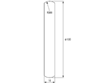
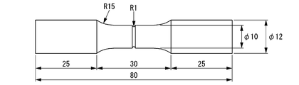
- Each ingot of the steels a to ab was hot forged to obtain a round bar having a diameter of 40 mm. Subsequently, after each round bar was annealed, it was cut to produce a small roller for a roller pitting test for evaluating the wear resistance shown in FIG. 3 and a large roller shown in FIG. Further, a cylindrical test piece for evaluating the rotational bending fatigue strength shown in FIG. 5 was prepared.
- test pieces were subjected to gas nitrocarburizing treatment under the following conditions.
- the test piece was charged into a gas soft nitriding furnace, NH 3 , H 2 , N 2 , and CO 2 gases were introduced into the furnace, and the soft nitriding treatment was performed under the conditions shown in Table 2-1 and Table 2-2. Was carried out.
- the total input flow rate of NH 3 , H 2 , and N 2 gas and the input flow rate of CO 2 gas were not changed during the treatment so that the input ratio of CO 2 gas was constant.
- the test piece after the soft nitriding treatment was oil-cooled using oil at 80 ° C.
- the H 2 partial pressure in the atmosphere was measured using a heat conduction type H 2 sensor directly mounted on the gas soft nitride furnace body. The difference in thermal conductivity between the standard gas and the measured gas was converted into gas concentration and measured. H 2 partial pressure during the gas nitrocarburizing treatment, was continuously measured.
- the NH 3 partial pressure was measured every 10 minutes using a glass tube type NH 3 analyzer mounted outside the furnace.
- the NH 3 flow rate, the H 2 flow rate, and the N 2 flow rate were adjusted so that the nitriding potential K N converged to the target value. Record the nitriding potential K N every 10 minutes, the minimum value being processed to derive the maximum value and average value.
- the compound layer can be confirmed as an uncorroded layer existing on the surface layer of steel.
- the ratio of the total area of voids (void area ratio, unit is%) to the area 90 ⁇ m 2 in the range of 3 ⁇ m depth from the outermost surface can be determined by an image processing application (manufactured by JEOL Ltd .; Anallysis Station). Obtained by. Then, the average value of the measured 10 visual fields was defined as the void area ratio (%). Even when the compound layer was less than 3 ⁇ m, the measurement target was similarly up to a depth of 3 ⁇ m from the surface.
- the hardness of the compound layer was measured by the following method using a nanoindentation device (manufactured by Hysiron; TI950).
- the Vickers hardness HV was measured from the obtained load-displacement curve by randomly pushing 50 points of the indenter with a pushing load of 10 mN at a position near the center in the thickness direction of the compound layer.
- Indenter is triangular pyramid (Berkovich) shape, hardness derivation complies with ISO14577-1, the conversion from nanoindentation hardness H IT to Vickers hardness HV, was performed by the following equation.
- HV 0.0924 x H IT (MPa)
- HV hardness
- roller pitting test was performed under the conditions shown in Table 4 by combining the above-mentioned small roller for the roller pitting test and the large roller for the roller pitting test having the shape shown in FIG.
- the unit of dimensions in FIGS. 3 and 4 is "mm".
- the large roller for roller peening test uses steel that meets the SCM420 standard of JIS G 4053 (2016), and is used in the general manufacturing process, that is, "normalizing-> test piece processing-> co-deposit carburizing by gas carburizing furnace-> After being produced by the process of "low temperature tempering ⁇ polishing", shot peening treatment with a projection pressure of 0.2 MPa was performed using a steel ball with a particle size of 0.8 mm for the purpose of imparting fine irregularities to the surface.
- the Vickers hardness HV at a position of 0.05 mm from the surface, that is, at a depth of 0.05 mm is 740 to 760, and the depth of the Vickers hardness Hv of 550 or more is 0.8 to 1.0 mm.
- the Vickers hardness HV at a position of 0.05 mm from the surface, that is, at a depth of 0.05 mm is 740 to 760, and the depth of the Vickers hardness Hv of 550 or more is 0.8 to 1.0 mm.
- Table 3 shows the test conditions for which the wear resistance was evaluated.
- the test was completed with 5 ⁇ 10 6 repetitions, and the wear depth of the small roller after the test was measured.
- a surface roughness shape measuring machine (manufactured by Tokyo Seimitsu Co., Ltd .; SURFCOM FLEX) scans the worn part of the small roller after the test along the spindle direction to acquire the cross-sectional shape profile, and the maximum of the obtained cross-sectional shape profile. The difference between the depth (wear part) and the minimum depth (non-wear part) was measured as the maximum wear depth.
- the value of the wear depth was calculated by measuring and averaging the maximum wear depths at five measurement positions on the same test piece (small roller). In the parts of the present invention, it was aimed that the wear depth was 10 ⁇ m or less.
- the goal was to have a maximum stress of 500 MPa or more in the fatigue limit.
- Test results The results are shown in Table 2-1 and Table 2-2.
- the steel composition and the conditions of the gas soft nitriding treatment were within the range of the present invention, the compound layer thickness was 3 ⁇ m or more and 20 ⁇ m or less, and the compound layer void area ratio was less than 12%.
- good results were obtained with a wear depth of less than 10 ⁇ m and a rotational bending fatigue strength of 500 MPa or more.
- test numbers 27 to 45 the composition of the steel and some of the conditions for the gas soft nitriding treatment are outside the scope of the present invention, and any one of the thickness of the compound layer, the area ratio of the ⁇ phase, and the void area ratio is determined. Alternatively, a plurality of characteristics did not reach the target value in the present invention. As a result, wear resistance or rotational bending fatigue strength did not meet the object of the present invention.
- Test number 27 is a comparative example in which the gas nitrocarburizing treatment temperature was too high during production. As a result, in Test No. 27, the void area ratio became excessive, and the wear resistance and the rotational bending fatigue strength were insufficient.
- Test number 28 is a comparative example in which the gas nitrocarburizing treatment temperature was too low during production. As a result, in Test No. 28, the thickness of the compound layer was insufficient, and the wear resistance and the rotational bending fatigue strength were insufficient.
- Test number 29 is a comparative example in which the gas nitrocarburizing treatment time was too long during production. As a result, in Test No. 29, the thickness of the compound layer became excessive, the void area ratio became excessive, and the wear resistance and the rotational bending fatigue strength were insufficient.
- Test number 30 is a comparative example in which the gas nitrocarburizing treatment time was too short at the time of production. As a result, in Test No.
- Test number 31 is a comparative example in which the nitriding potential K N becomes too high during manufacturing. As a result, in Test No. 31, the void area ratio became excessive, and the wear resistance and the rotational bending fatigue strength were insufficient.
- Test number 32 is a comparative example in which the nitriding potential K N was too low during production. As a result, in Test No. 32, the thickness of the compound layer was insufficient, and the wear resistance and the rotational bending fatigue strength were insufficient.
- Test number 33 is a comparative example in which the gas nitrocarburizing treatment time was too long during production. As a result, in Test No.
- Test number 34 is a comparative example in which the average nitriding potential K Nave was too low at the time of manufacture. As a result, in Test No. 34, the thickness of the compound layer was insufficient, the ⁇ area ratio was insufficient, and the wear resistance and the rotational bending fatigue strength were insufficient.
- Test number 35 is a comparative example in which the carburizing gas input ratio was too high at the time of production. As a result, in Test No. 35, the thickness of the compound layer was insufficient, and the wear resistance and the rotational bending fatigue strength were insufficient.
- Test number 36 is a comparative example in which the carburizing gas input ratio was too low at the time of production (that is, nitriding was performed instead of soft nitriding). As a result, in test number 36, the ⁇ area ratio was insufficient and the wear resistance was insufficient.
- Serial number 37 (steel u) is a comparative example in which ⁇ 2.1 ⁇ C + 0.04 ⁇ Mn + 0.5 ⁇ Cr + 1.8 ⁇ V-1.5 ⁇ Mo was too high in the chemical composition of the steel core portion. As a result, in Test No. 37, the thickness of the compound layer was insufficient, and the wear resistance and the rotational bending fatigue strength were insufficient.
- Serial number 38 (steel v) is a comparative example in which ⁇ 2.1 ⁇ C + 0.04 ⁇ Mn + 0.5 ⁇ Cr + 1.8 ⁇ V-1.5 ⁇ Mo was too low in the chemical composition of the steel core portion. As a result, in Test No. 38, the thickness of the compound layer became excessive, and the rotational bending fatigue strength was insufficient.
- Serial number 39 (steel w) is a comparative example in which the amount of C in the steel core is too low. As a result, the wear resistance of test number 39 was insufficient.
- Serial number 40 (steel x) is a comparative example in which the amount of Mn in the steel core is too low. As a result, in Test No.
- Serial number 41 (steel y) is a comparative example in which the amount of Cr in the steel core is too low. As a result, in Test No. 41, the wear resistance and the rotational bending fatigue strength were insufficient.
- Serial number 42 (steel z) is a comparative example in which the amount of V in the steel core is too low. As a result, in Test No. 42, the wear resistance and the rotational bending fatigue strength were insufficient.
- Serial number 43 (steel aa) is a comparative example in which the P amount of the steel core portion is too high. As a result, in Test No. 43, the wear resistance and the rotational bending fatigue strength were insufficient.
- Serial number 44 (steel ab) is a comparative example in which the S amount of the steel core portion is too high. As a result, in Test No. 44, the wear resistance and the rotational bending fatigue strength were insufficient.
- Production number 45 is a comparative example in which the nitriding potential K N and the average nitriding potential K Nave were too high at the time of production. As a result, in Test No. 45, the thickness of the compound layer became excessive, the void area ratio became excessive, and the wear resistance and the rotational bending fatigue strength were insufficient.
- a soft nitriding-treated part having excellent wear resistance and rotational bending fatigue strength and a method for manufacturing the same, and a continuously variable transmission (CVT) having particularly excellent wear resistance and bending fatigue strength.
- CVT continuously variable transmission
Landscapes
- Chemical & Material Sciences (AREA)
- Engineering & Computer Science (AREA)
- Materials Engineering (AREA)
- Mechanical Engineering (AREA)
- Metallurgy (AREA)
- Organic Chemistry (AREA)
- Physics & Mathematics (AREA)
- Thermal Sciences (AREA)
- Crystallography & Structural Chemistry (AREA)
- Chemical Kinetics & Catalysis (AREA)
- Solid-Phase Diffusion Into Metallic Material Surfaces (AREA)
Priority Applications (3)
| Application Number | Priority Date | Filing Date | Title |
|---|---|---|---|
| DE112020006870.6T DE112020006870T5 (de) | 2020-03-11 | 2020-03-11 | Gasweichnitrierbehandeltes bauteil und herstellungsverfahren davon |
| JP2022507086A JP7277859B2 (ja) | 2020-03-11 | 2020-03-11 | ガス軟窒化処理部品及びその製造方法 |
| PCT/JP2020/010585 WO2021181570A1 (ja) | 2020-03-11 | 2020-03-11 | ガス軟窒化処理部品及びその製造方法 |
Applications Claiming Priority (1)
| Application Number | Priority Date | Filing Date | Title |
|---|---|---|---|
| PCT/JP2020/010585 WO2021181570A1 (ja) | 2020-03-11 | 2020-03-11 | ガス軟窒化処理部品及びその製造方法 |
Publications (1)
| Publication Number | Publication Date |
|---|---|
| WO2021181570A1 true WO2021181570A1 (ja) | 2021-09-16 |
Family
ID=77670934
Family Applications (1)
| Application Number | Title | Priority Date | Filing Date |
|---|---|---|---|
| PCT/JP2020/010585 Ceased WO2021181570A1 (ja) | 2020-03-11 | 2020-03-11 | ガス軟窒化処理部品及びその製造方法 |
Country Status (3)
| Country | Link |
|---|---|
| JP (1) | JP7277859B2 (https=) |
| DE (1) | DE112020006870T5 (https=) |
| WO (1) | WO2021181570A1 (https=) |
Cited By (1)
| Publication number | Priority date | Publication date | Assignee | Title |
|---|---|---|---|---|
| CN114107821A (zh) * | 2021-11-26 | 2022-03-01 | 钢铁研究总院 | 一种高韧性超高强度钢及其制造方法 |
Families Citing this family (1)
| Publication number | Priority date | Publication date | Assignee | Title |
|---|---|---|---|---|
| KR20250091975A (ko) * | 2023-12-14 | 2025-06-23 | 주식회사 포스코 | 코팅 파스너 및 그 제조방법 |
Citations (3)
| Publication number | Priority date | Publication date | Assignee | Title |
|---|---|---|---|---|
| JP2014520957A (ja) * | 2011-06-30 | 2014-08-25 | ローベルト ボツシユ ゲゼルシヤフト ミツト ベシユレンクテル ハフツング | 駆動ベルトのリング部品のための製造方法 |
| WO2018066666A1 (ja) * | 2016-10-05 | 2018-04-12 | 新日鐵住金株式会社 | 窒化処理部品及びその製造方法 |
| JP2019019396A (ja) * | 2017-07-20 | 2019-02-07 | 新日鐵住金株式会社 | 窒化部品および窒化処理方法 |
Family Cites Families (2)
| Publication number | Priority date | Publication date | Assignee | Title |
|---|---|---|---|---|
| CN107406959B (zh) | 2015-03-25 | 2020-02-04 | 日本制铁株式会社 | 耐磨性和耐点蚀性优异的氮化处理部件和软氮化处理部件以及氮化处理方法、软氮化处理方法 |
| EP3712287B1 (en) | 2017-11-16 | 2023-07-19 | Nippon Steel Corporation | Nitrided part |
-
2020
- 2020-03-11 JP JP2022507086A patent/JP7277859B2/ja active Active
- 2020-03-11 WO PCT/JP2020/010585 patent/WO2021181570A1/ja not_active Ceased
- 2020-03-11 DE DE112020006870.6T patent/DE112020006870T5/de active Pending
Patent Citations (3)
| Publication number | Priority date | Publication date | Assignee | Title |
|---|---|---|---|---|
| JP2014520957A (ja) * | 2011-06-30 | 2014-08-25 | ローベルト ボツシユ ゲゼルシヤフト ミツト ベシユレンクテル ハフツング | 駆動ベルトのリング部品のための製造方法 |
| WO2018066666A1 (ja) * | 2016-10-05 | 2018-04-12 | 新日鐵住金株式会社 | 窒化処理部品及びその製造方法 |
| JP2019019396A (ja) * | 2017-07-20 | 2019-02-07 | 新日鐵住金株式会社 | 窒化部品および窒化処理方法 |
Cited By (1)
| Publication number | Priority date | Publication date | Assignee | Title |
|---|---|---|---|---|
| CN114107821A (zh) * | 2021-11-26 | 2022-03-01 | 钢铁研究总院 | 一种高韧性超高强度钢及其制造方法 |
Also Published As
| Publication number | Publication date |
|---|---|
| JPWO2021181570A1 (https=) | 2021-09-16 |
| DE112020006870T5 (de) | 2022-12-29 |
| JP7277859B2 (ja) | 2023-05-19 |
Similar Documents
| Publication | Publication Date | Title |
|---|---|---|
| JP6922998B2 (ja) | 窒化処理部品 | |
| JP6388075B2 (ja) | 耐摩耗性と耐ピッティング性に優れた窒化、軟窒化処理部品および窒化、軟窒化処理方法 | |
| JP5503344B2 (ja) | 高強度肌焼き鋼部品およびその製造方法 | |
| JP5182067B2 (ja) | 真空浸炭または真空浸炭窒化用の鋼材 | |
| EP2412836A1 (en) | Maraging steel strip | |
| JP5123335B2 (ja) | クランクシャフトおよびその製造方法 | |
| JP6769491B2 (ja) | 窒化処理部品及びその製造方法 | |
| JP7364895B2 (ja) | 鋼部品及びその製造方法 | |
| JP6601358B2 (ja) | 浸炭部品およびその製造方法 | |
| JP5206271B2 (ja) | 鋼製の浸炭窒化部品 | |
| JP6766876B2 (ja) | 窒化処理部品及びその製造方法 | |
| WO2016152167A1 (ja) | 軟窒化用鋼および部品並びにこれらの製造方法 | |
| JP6772499B2 (ja) | 鋼部品及びその製造方法 | |
| JP7295378B2 (ja) | ガス軟窒化処理部品及びその製造方法 | |
| JP7277859B2 (ja) | ガス軟窒化処理部品及びその製造方法 | |
| JP7180300B2 (ja) | 鋼部品及びその製造方法 | |
| JP5381171B2 (ja) | 高強度肌焼鋼部品の製造方法 | |
| JP5272609B2 (ja) | 鋼製の浸炭窒化部品 | |
| JP2022079181A (ja) | 窒化用鋼および窒化処理部品 | |
| TWI630278B (zh) | Surface hardened steel | |
| JP6953871B2 (ja) | 浸炭部品および浸炭窒化部品 | |
| JP2007332421A (ja) | 軟窒化部品の製造方法 | |
| JP7800789B1 (ja) | 鋼および鋼部品 | |
| CN108291286A (zh) | 碳氮共渗用钢材和碳氮共渗零件 | |
| WO2026042642A1 (ja) | 鋼および鋼部品 |
Legal Events
| Date | Code | Title | Description |
|---|---|---|---|
| 121 | Ep: the epo has been informed by wipo that ep was designated in this application |
Ref document number: 20923892 Country of ref document: EP Kind code of ref document: A1 |
|
| ENP | Entry into the national phase |
Ref document number: 2022507086 Country of ref document: JP Kind code of ref document: A |
|
| 122 | Ep: pct application non-entry in european phase |
Ref document number: 20923892 Country of ref document: EP Kind code of ref document: A1 |