WO2021177307A1 - Soufflante - Google Patents
Soufflante Download PDFInfo
- Publication number
- WO2021177307A1 WO2021177307A1 PCT/JP2021/007961 JP2021007961W WO2021177307A1 WO 2021177307 A1 WO2021177307 A1 WO 2021177307A1 JP 2021007961 W JP2021007961 W JP 2021007961W WO 2021177307 A1 WO2021177307 A1 WO 2021177307A1
- Authority
- WO
- WIPO (PCT)
- Prior art keywords
- purge gas
- casing
- gas
- shaft hole
- rotating shaft
- Prior art date
Links
- 238000010926 purge Methods 0.000 claims abstract description 232
- 239000000446 fuel Substances 0.000 claims description 55
- 238000003860 storage Methods 0.000 claims description 36
- 230000002093 peripheral effect Effects 0.000 claims description 24
- 230000008595 infiltration Effects 0.000 abstract 1
- 238000001764 infiltration Methods 0.000 abstract 1
- 230000004941 influx Effects 0.000 abstract 1
- 239000007789 gas Substances 0.000 description 393
- 238000001816 cooling Methods 0.000 description 18
- 239000002737 fuel gas Substances 0.000 description 16
- 238000010248 power generation Methods 0.000 description 11
- UGFAIRIUMAVXCW-UHFFFAOYSA-N Carbon monoxide Chemical compound [O+]#[C-] UGFAIRIUMAVXCW-UHFFFAOYSA-N 0.000 description 9
- 229910002091 carbon monoxide Inorganic materials 0.000 description 9
- 239000001257 hydrogen Substances 0.000 description 8
- 229910052739 hydrogen Inorganic materials 0.000 description 8
- VNWKTOKETHGBQD-UHFFFAOYSA-N methane Chemical compound C VNWKTOKETHGBQD-UHFFFAOYSA-N 0.000 description 8
- 238000007789 sealing Methods 0.000 description 8
- 239000007787 solid Substances 0.000 description 8
- UFHFLCQGNIYNRP-UHFFFAOYSA-N Hydrogen Chemical compound [H][H] UFHFLCQGNIYNRP-UHFFFAOYSA-N 0.000 description 7
- XLYOFNOQVPJJNP-UHFFFAOYSA-N water Substances O XLYOFNOQVPJJNP-UHFFFAOYSA-N 0.000 description 7
- 101100346453 Arabidopsis thaliana MRS2-5 gene Proteins 0.000 description 6
- IJGRMHOSHXDMSA-UHFFFAOYSA-N Atomic nitrogen Chemical compound N#N IJGRMHOSHXDMSA-UHFFFAOYSA-N 0.000 description 5
- 230000000694 effects Effects 0.000 description 5
- 230000009545 invasion Effects 0.000 description 5
- 239000000463 material Substances 0.000 description 5
- 238000000034 method Methods 0.000 description 5
- 230000008569 process Effects 0.000 description 5
- QVGXLLKOCUKJST-UHFFFAOYSA-N atomic oxygen Chemical compound [O] QVGXLLKOCUKJST-UHFFFAOYSA-N 0.000 description 4
- 238000009833 condensation Methods 0.000 description 4
- 230000005494 condensation Effects 0.000 description 4
- 238000005868 electrolysis reaction Methods 0.000 description 4
- 238000010828 elution Methods 0.000 description 4
- 239000004519 grease Substances 0.000 description 4
- 238000010438 heat treatment Methods 0.000 description 4
- 239000001301 oxygen Substances 0.000 description 4
- 229910052760 oxygen Inorganic materials 0.000 description 4
- 230000005855 radiation Effects 0.000 description 4
- 239000004215 Carbon black (E152) Substances 0.000 description 3
- 230000009471 action Effects 0.000 description 3
- 239000000919 ceramic Substances 0.000 description 3
- 229910001873 dinitrogen Inorganic materials 0.000 description 3
- 229930195733 hydrocarbon Natural products 0.000 description 3
- 150000002430 hydrocarbons Chemical class 0.000 description 3
- 230000001590 oxidative effect Effects 0.000 description 3
- 238000005192 partition Methods 0.000 description 3
- 238000011144 upstream manufacturing Methods 0.000 description 3
- RYGMFSIKBFXOCR-UHFFFAOYSA-N Copper Chemical compound [Cu] RYGMFSIKBFXOCR-UHFFFAOYSA-N 0.000 description 2
- 229910052581 Si3N4 Inorganic materials 0.000 description 2
- 230000004323 axial length Effects 0.000 description 2
- 230000008901 benefit Effects 0.000 description 2
- 238000007664 blowing Methods 0.000 description 2
- 230000008859 change Effects 0.000 description 2
- 238000006243 chemical reaction Methods 0.000 description 2
- 239000003245 coal Substances 0.000 description 2
- 239000000567 combustion gas Substances 0.000 description 2
- 230000006835 compression Effects 0.000 description 2
- 238000007906 compression Methods 0.000 description 2
- 239000002826 coolant Substances 0.000 description 2
- 229910052802 copper Inorganic materials 0.000 description 2
- 239000010949 copper Substances 0.000 description 2
- 238000001514 detection method Methods 0.000 description 2
- 230000006866 deterioration Effects 0.000 description 2
- 239000003792 electrolyte Substances 0.000 description 2
- 239000000835 fiber Substances 0.000 description 2
- 238000010304 firing Methods 0.000 description 2
- 150000002431 hydrogen Chemical class 0.000 description 2
- 239000011261 inert gas Substances 0.000 description 2
- 239000000314 lubricant Substances 0.000 description 2
- 238000004519 manufacturing process Methods 0.000 description 2
- 238000007254 oxidation reaction Methods 0.000 description 2
- 230000000149 penetrating effect Effects 0.000 description 2
- 238000006722 reduction reaction Methods 0.000 description 2
- HQVNEWCFYHHQES-UHFFFAOYSA-N silicon nitride Chemical compound N12[Si]34N5[Si]62N3[Si]51N64 HQVNEWCFYHHQES-UHFFFAOYSA-N 0.000 description 2
- 238000000629 steam reforming Methods 0.000 description 2
- 238000004804 winding Methods 0.000 description 2
- 229910000531 Co alloy Inorganic materials 0.000 description 1
- 229910018487 Ni—Cr Inorganic materials 0.000 description 1
- 229910045601 alloy Inorganic materials 0.000 description 1
- 239000000956 alloy Substances 0.000 description 1
- 239000003575 carbonaceous material Substances 0.000 description 1
- 238000002485 combustion reaction Methods 0.000 description 1
- 238000004891 communication Methods 0.000 description 1
- 239000000110 cooling liquid Substances 0.000 description 1
- 238000001035 drying Methods 0.000 description 1
- 230000005611 electricity Effects 0.000 description 1
- 239000012530 fluid Substances 0.000 description 1
- -1 for example Substances 0.000 description 1
- 238000002309 gasification Methods 0.000 description 1
- 239000010763 heavy fuel oil Substances 0.000 description 1
- 239000012535 impurity Substances 0.000 description 1
- 238000009413 insulation Methods 0.000 description 1
- 150000002500 ions Chemical class 0.000 description 1
- 230000033001 locomotion Effects 0.000 description 1
- 230000001050 lubricating effect Effects 0.000 description 1
- VUZPPFZMUPKLLV-UHFFFAOYSA-N methane;hydrate Chemical compound C.O VUZPPFZMUPKLLV-UHFFFAOYSA-N 0.000 description 1
- 239000003345 natural gas Substances 0.000 description 1
- 229910052757 nitrogen Inorganic materials 0.000 description 1
- 230000003647 oxidation Effects 0.000 description 1
- AHKZTVQIVOEVFO-UHFFFAOYSA-N oxide(2-) Chemical compound [O-2] AHKZTVQIVOEVFO-UHFFFAOYSA-N 0.000 description 1
- 239000002994 raw material Substances 0.000 description 1
- 230000003134 recirculating effect Effects 0.000 description 1
- 230000009467 reduction Effects 0.000 description 1
- 238000002407 reforming Methods 0.000 description 1
- HBMJWWWQQXIZIP-UHFFFAOYSA-N silicon carbide Chemical compound [Si+]#[C-] HBMJWWWQQXIZIP-UHFFFAOYSA-N 0.000 description 1
- 230000003068 static effect Effects 0.000 description 1
- 238000009423 ventilation Methods 0.000 description 1
Images


Classifications
-
- F—MECHANICAL ENGINEERING; LIGHTING; HEATING; WEAPONS; BLASTING
- F04—POSITIVE - DISPLACEMENT MACHINES FOR LIQUIDS; PUMPS FOR LIQUIDS OR ELASTIC FLUIDS
- F04D—NON-POSITIVE-DISPLACEMENT PUMPS
- F04D29/00—Details, component parts, or accessories
- F04D29/40—Casings; Connections of working fluid
- F04D29/42—Casings; Connections of working fluid for radial or helico-centrifugal pumps
- F04D29/4206—Casings; Connections of working fluid for radial or helico-centrifugal pumps especially adapted for elastic fluid pumps
-
- F—MECHANICAL ENGINEERING; LIGHTING; HEATING; WEAPONS; BLASTING
- F04—POSITIVE - DISPLACEMENT MACHINES FOR LIQUIDS; PUMPS FOR LIQUIDS OR ELASTIC FLUIDS
- F04D—NON-POSITIVE-DISPLACEMENT PUMPS
- F04D29/00—Details, component parts, or accessories
- F04D29/08—Sealings
- F04D29/10—Shaft sealings
-
- F—MECHANICAL ENGINEERING; LIGHTING; HEATING; WEAPONS; BLASTING
- F04—POSITIVE - DISPLACEMENT MACHINES FOR LIQUIDS; PUMPS FOR LIQUIDS OR ELASTIC FLUIDS
- F04D—NON-POSITIVE-DISPLACEMENT PUMPS
- F04D29/00—Details, component parts, or accessories
- F04D29/05—Shafts or bearings, or assemblies thereof, specially adapted for elastic fluid pumps
- F04D29/053—Shafts
-
- F—MECHANICAL ENGINEERING; LIGHTING; HEATING; WEAPONS; BLASTING
- F04—POSITIVE - DISPLACEMENT MACHINES FOR LIQUIDS; PUMPS FOR LIQUIDS OR ELASTIC FLUIDS
- F04D—NON-POSITIVE-DISPLACEMENT PUMPS
- F04D17/00—Radial-flow pumps, e.g. centrifugal pumps; Helico-centrifugal pumps
- F04D17/08—Centrifugal pumps
-
- F—MECHANICAL ENGINEERING; LIGHTING; HEATING; WEAPONS; BLASTING
- F04—POSITIVE - DISPLACEMENT MACHINES FOR LIQUIDS; PUMPS FOR LIQUIDS OR ELASTIC FLUIDS
- F04D—NON-POSITIVE-DISPLACEMENT PUMPS
- F04D25/00—Pumping installations or systems
- F04D25/02—Units comprising pumps and their driving means
- F04D25/06—Units comprising pumps and their driving means the pump being electrically driven
-
- F—MECHANICAL ENGINEERING; LIGHTING; HEATING; WEAPONS; BLASTING
- F04—POSITIVE - DISPLACEMENT MACHINES FOR LIQUIDS; PUMPS FOR LIQUIDS OR ELASTIC FLUIDS
- F04D—NON-POSITIVE-DISPLACEMENT PUMPS
- F04D29/00—Details, component parts, or accessories
- F04D29/05—Shafts or bearings, or assemblies thereof, specially adapted for elastic fluid pumps
- F04D29/056—Bearings
- F04D29/059—Roller bearings
-
- F—MECHANICAL ENGINEERING; LIGHTING; HEATING; WEAPONS; BLASTING
- F04—POSITIVE - DISPLACEMENT MACHINES FOR LIQUIDS; PUMPS FOR LIQUIDS OR ELASTIC FLUIDS
- F04D—NON-POSITIVE-DISPLACEMENT PUMPS
- F04D29/00—Details, component parts, or accessories
- F04D29/08—Sealings
- F04D29/10—Shaft sealings
- F04D29/102—Shaft sealings especially adapted for elastic fluid pumps
- F04D29/104—Shaft sealings especially adapted for elastic fluid pumps the sealing fluid being other than the working fluid or being the working fluid treated
-
- F—MECHANICAL ENGINEERING; LIGHTING; HEATING; WEAPONS; BLASTING
- F04—POSITIVE - DISPLACEMENT MACHINES FOR LIQUIDS; PUMPS FOR LIQUIDS OR ELASTIC FLUIDS
- F04D—NON-POSITIVE-DISPLACEMENT PUMPS
- F04D29/00—Details, component parts, or accessories
- F04D29/26—Rotors specially for elastic fluids
- F04D29/28—Rotors specially for elastic fluids for centrifugal or helico-centrifugal pumps for radial-flow or helico-centrifugal pumps
- F04D29/281—Rotors specially for elastic fluids for centrifugal or helico-centrifugal pumps for radial-flow or helico-centrifugal pumps for fans or blowers
-
- F—MECHANICAL ENGINEERING; LIGHTING; HEATING; WEAPONS; BLASTING
- F04—POSITIVE - DISPLACEMENT MACHINES FOR LIQUIDS; PUMPS FOR LIQUIDS OR ELASTIC FLUIDS
- F04D—NON-POSITIVE-DISPLACEMENT PUMPS
- F04D29/00—Details, component parts, or accessories
- F04D29/58—Cooling; Heating; Diminishing heat transfer
- F04D29/582—Cooling; Heating; Diminishing heat transfer specially adapted for elastic fluid pumps
- F04D29/5853—Cooling; Heating; Diminishing heat transfer specially adapted for elastic fluid pumps heat insulation or conduction
-
- H—ELECTRICITY
- H01—ELECTRIC ELEMENTS
- H01M—PROCESSES OR MEANS, e.g. BATTERIES, FOR THE DIRECT CONVERSION OF CHEMICAL ENERGY INTO ELECTRICAL ENERGY
- H01M8/00—Fuel cells; Manufacture thereof
- H01M8/04—Auxiliary arrangements, e.g. for control of pressure or for circulation of fluids
-
- H—ELECTRICITY
- H01—ELECTRIC ELEMENTS
- H01M—PROCESSES OR MEANS, e.g. BATTERIES, FOR THE DIRECT CONVERSION OF CHEMICAL ENERGY INTO ELECTRICAL ENERGY
- H01M8/00—Fuel cells; Manufacture thereof
- H01M8/04—Auxiliary arrangements, e.g. for control of pressure or for circulation of fluids
- H01M8/04082—Arrangements for control of reactant parameters, e.g. pressure or concentration
- H01M8/04089—Arrangements for control of reactant parameters, e.g. pressure or concentration of gaseous reactants
- H01M8/04097—Arrangements for control of reactant parameters, e.g. pressure or concentration of gaseous reactants with recycling of the reactants
-
- H—ELECTRICITY
- H01—ELECTRIC ELEMENTS
- H01M—PROCESSES OR MEANS, e.g. BATTERIES, FOR THE DIRECT CONVERSION OF CHEMICAL ENERGY INTO ELECTRICAL ENERGY
- H01M8/00—Fuel cells; Manufacture thereof
- H01M8/04—Auxiliary arrangements, e.g. for control of pressure or for circulation of fluids
- H01M8/04223—Auxiliary arrangements, e.g. for control of pressure or for circulation of fluids during start-up or shut-down; Depolarisation or activation, e.g. purging; Means for short-circuiting defective fuel cells
- H01M8/04231—Purging of the reactants
-
- F—MECHANICAL ENGINEERING; LIGHTING; HEATING; WEAPONS; BLASTING
- F04—POSITIVE - DISPLACEMENT MACHINES FOR LIQUIDS; PUMPS FOR LIQUIDS OR ELASTIC FLUIDS
- F04D—NON-POSITIVE-DISPLACEMENT PUMPS
- F04D17/00—Radial-flow pumps, e.g. centrifugal pumps; Helico-centrifugal pumps
- F04D17/08—Centrifugal pumps
- F04D17/10—Centrifugal pumps for compressing or evacuating
-
- F—MECHANICAL ENGINEERING; LIGHTING; HEATING; WEAPONS; BLASTING
- F04—POSITIVE - DISPLACEMENT MACHINES FOR LIQUIDS; PUMPS FOR LIQUIDS OR ELASTIC FLUIDS
- F04D—NON-POSITIVE-DISPLACEMENT PUMPS
- F04D25/00—Pumping installations or systems
- F04D25/02—Units comprising pumps and their driving means
- F04D25/06—Units comprising pumps and their driving means the pump being electrically driven
- F04D25/0606—Units comprising pumps and their driving means the pump being electrically driven the electric motor being specially adapted for integration in the pump
-
- F—MECHANICAL ENGINEERING; LIGHTING; HEATING; WEAPONS; BLASTING
- F04—POSITIVE - DISPLACEMENT MACHINES FOR LIQUIDS; PUMPS FOR LIQUIDS OR ELASTIC FLUIDS
- F04D—NON-POSITIVE-DISPLACEMENT PUMPS
- F04D29/00—Details, component parts, or accessories
- F04D29/26—Rotors specially for elastic fluids
- F04D29/28—Rotors specially for elastic fluids for centrifugal or helico-centrifugal pumps for radial-flow or helico-centrifugal pumps
- F04D29/284—Rotors specially for elastic fluids for centrifugal or helico-centrifugal pumps for radial-flow or helico-centrifugal pumps for compressors
-
- F—MECHANICAL ENGINEERING; LIGHTING; HEATING; WEAPONS; BLASTING
- F05—INDEXING SCHEMES RELATING TO ENGINES OR PUMPS IN VARIOUS SUBCLASSES OF CLASSES F01-F04
- F05D—INDEXING SCHEME FOR ASPECTS RELATING TO NON-POSITIVE-DISPLACEMENT MACHINES OR ENGINES, GAS-TURBINES OR JET-PROPULSION PLANTS
- F05D2210/00—Working fluids
- F05D2210/10—Kind or type
- F05D2210/12—Kind or type gaseous, i.e. compressible
-
- F—MECHANICAL ENGINEERING; LIGHTING; HEATING; WEAPONS; BLASTING
- F05—INDEXING SCHEMES RELATING TO ENGINES OR PUMPS IN VARIOUS SUBCLASSES OF CLASSES F01-F04
- F05D—INDEXING SCHEME FOR ASPECTS RELATING TO NON-POSITIVE-DISPLACEMENT MACHINES OR ENGINES, GAS-TURBINES OR JET-PROPULSION PLANTS
- F05D2240/00—Components
- F05D2240/60—Shafts
- F05D2240/61—Hollow
-
- Y—GENERAL TAGGING OF NEW TECHNOLOGICAL DEVELOPMENTS; GENERAL TAGGING OF CROSS-SECTIONAL TECHNOLOGIES SPANNING OVER SEVERAL SECTIONS OF THE IPC; TECHNICAL SUBJECTS COVERED BY FORMER USPC CROSS-REFERENCE ART COLLECTIONS [XRACs] AND DIGESTS
- Y02—TECHNOLOGIES OR APPLICATIONS FOR MITIGATION OR ADAPTATION AGAINST CLIMATE CHANGE
- Y02E—REDUCTION OF GREENHOUSE GAS [GHG] EMISSIONS, RELATED TO ENERGY GENERATION, TRANSMISSION OR DISTRIBUTION
- Y02E60/00—Enabling technologies; Technologies with a potential or indirect contribution to GHG emissions mitigation
- Y02E60/30—Hydrogen technology
- Y02E60/50—Fuel cells
Definitions
- the present invention relates to a blower, and particularly to a blower suitable for boosting and blowing air from a fuel cell, an electrolytic cell, or the like.
- Blowers that can suck in the gas to be blown and boost the pressure to make the temperature inside the furnaces of various heat treatment furnaces and firing furnaces uniform and improve the heating efficiency have been known for some time.
- Solid Oxide Fuel Cell Solid Oxide Fuel Cell
- humidified high-temperature exhaust gas hereinafter, also referred to as anode off gas
- the unreacted residual fuel in the exhaust gas can be reused, and the reaction-generated water without impurities can be used for so-called steam reforming, which can increase the power generation efficiency.
- a blower that boosts and blows the anode off gas to the fuel cell so that it can be recirculated that is, a so-called recirculation blower is used.
- a water electrolyzer with high electrolysis efficiency for hydrogen production utilizing the reverse reaction of a solid oxide fuel cell for example, a solid oxide electrolysis cell (Solid Oxide Electrolysis Cell) has recently been developed. Since hydrogen is produced by the high-temperature steam electrolysis method, a blower is used in such an apparatus to compress the produced gas and recirculate it to the fuel electrode to prevent oxidative deterioration of the fuel electrode.
- a blower is used in such an apparatus to compress the produced gas and recirculate it to the fuel electrode to prevent oxidative deterioration of the fuel electrode.
- the blower described in Patent Document 1 is arranged between an impeller and a heat-resistant impeller that is cantilevered and supported by a rotating shaft, a bearing that rotatably supports the rotating shaft of the impeller with respect to a casing, and an impeller and a bearing. It is provided with a heat insulating layer and a cooling unit arranged between the heat insulating layer and the bearing.
- the first pair of magnetic joints is provided at the rear end on the side opposite to the impeller of the rotating shaft.
- a non-magnetic partition wall is disposed between the first joint body and the second joint body of the magnetic joint mounted on the tip of the drive motor shaft. The space surrounding the rotation axis of the impeller is shielded and sealed from the outside by a non-magnetic partition wall and a casing.
- Patent Document 2 is a blower (compressor) that sucks and compresses process gas from a suction port by the rotation of a rotating body, and adopts a dry gas seal for the shaft seal of the rotating shaft of the rotating body, while drying the dry gas.
- a gas seal is described in which a part of the process gas is supplied and the gas discharged to the atmosphere side through a slight gap between the rotating ring and the stationary ring is flared.
- the conventional blower as described in Patent Document 1 described above has an advantage that a completely gas tight state can be established in which the space surrounding the rotation axis of the impeller is blocked and sealed from the outside by a non-magnetic partition wall and a casing. ..
- An object of the present invention is to provide a blower that can surely prevent a target gas from entering a shaft hole with a simple configuration in order to solve the above-mentioned conventional unsolved problems.
- the blower according to the present invention has a first casing in which a gas passage into which a target gas is introduced and a shaft hole communicating with the gas passage are formed, and the shaft hole of the first casing.
- a rotary shaft rotatably inserted into the shaft, an impeller housed in the first casing on the front end side of the rotary shaft, and an impeller that can rotate integrally with the rotary shaft, and a motor that drives the rotary shaft from the rear end side.
- a second casing having an internal space communicating with the shaft hole and supporting the rotating shaft via a bearing, and a purge gas having a pressure higher than that in the shaft hole of the first casing are applied to the internal space of the second casing.
- a high-pressure purge gas is introduced into the internal space of the second casing that rotatably supports the rotating shaft via the bearing from the inside of the shaft hole communicating with the gas passage of the first casing. Therefore, the high temperature gas introduced into the gas passage of the first casing is prevented from entering the shaft hole on the back surface side of the impeller by the purge gas on the internal space side of the second casing.
- the purge gas pressure may be substantially constant or variable.
- the purge gas when the purge gas is introduced into the internal space of the second casing by the purge gas introducing means, the purge gas is at least closer to the shaft hole side than the bearing in the internal space. It can be configured so that the pressure of the purge gas is maintained at a higher pressure than the inside of the shaft hole while being filled.
- the purge gas introducing means should be always operated.
- the high temperature gas is discharged from the fuel electrode side of the fuel cell, and the purge gas contains at least the fuel component of the fuel cell, and the internal space of the second casing is provided.
- the purge gas may flow into the gas passage side of the first casing through an annular gap around the rotating shaft in the shaft hole.
- the exhaust gas (anodic off gas) of the fuel cell is recirculated to the fuel gas supply path side together with the H 2 O generated by the power generation, but the dry purge gas containing the fuel component is first from the internal space of the second casing. It can flow into the shaft hole of the casing and flow into the gas passage side of the first casing. Therefore, the humidified exhaust gas from the fuel electrode side is effectively suppressed from entering the internal space of the second casing, and the recirculated exhaust gas is not contaminated by the purge gas.
- the first casing is provided with a heat insulating portion having a substantially plate-like body located on the back surface side of the impeller through which the rotating shaft penetrates, and the purge gas is introduced into the internal space.
- a part of the purge gas passage introduced from the bearing to the shaft hole side may be configured to open in the vicinity of the rear end of the shaft hole on the bearing side from the heat insulating portion.
- the heat insulating portion has an airtight wall surface having a thermal conductivity smaller than that of the second casing at least in the vicinity of the shaft hole, and the airtight wall surface is the back surface of the impeller. It may have a high temperature side wall surface portion facing with a predetermined gap, a cylindrical wall surface portion forming the shaft hole, and a low temperature side wall surface portion located in the vicinity of the opening of the purge gas passage.
- a preferred embodiment of the present invention is an annular gas storage in which a part of the purge gas passage is opened on the rear end side of the shaft hole by a plurality of members including at least the heat insulating portion, the rotating shaft and the bearing.
- the chamber is defined, and a gap passage having a smaller radial gap dimension than the annular gas storage chamber is formed between the cylindrical wall surface portion of the airtight wall surface of the heat insulating portion and the rotating shaft. can do.
- the air in the gas storage chamber where the bearing is exposed on the rear end side of the shaft hole can be quickly replaced with purge gas at the initial stage of operation, and the purge gas is stably supplied to the annular gas storage chamber on the rear end side of the shaft hole. Therefore, the dry gas sealing performance by the purge gas can be stably ensured regardless of the pressure fluctuation of the exhaust gas on the impeller side due to the load fluctuation.
- a part of the purge gas passage is opened on the outer peripheral surface on the tip end side of the rotating shaft on the rear end side of the shaft hole and on the shaft hole side of the bearing. At the same time, it can be configured to extend in the radial direction and the rear side in the axial direction of the rotating shaft.
- the purge gas can be quickly and surely flowed into the shaft hole side from the bearing in the internal space of the second casing by a part of the purge gas passage passing through the rotating shaft, and the humidified exhaust gas in the first casing can be discharged. It is possible to more effectively suppress the invasion and dew condensation in the shaft hole and the bearing.
- a part of the purge gas passage is on the rear end side of the rotating shaft with respect to the bearing and radially inward from the outer peripheral surface on the tip end side of the rotating shaft. It can be configured to be open on the end face extending in the radial direction of the rotating shaft.
- the purge gas is urged in the outward radiation direction by centrifugal force as the purge gas passage extending in the radial direction rotates, and from the rear end side of the purge gas passage. Inhalation of purge gas will be promoted.
- the first casing is provided with a heat insulating portion having a substantially plate-like body located on the back surface side of the impeller through which the rotating shaft penetrates, and the purge gas is passed through the internal space.
- a part of the purge gas passage introduced from the bearing to the shaft hole side may be configured to open in the radial direction toward the inner peripheral surface of the bearing.
- a part of the purge gas passage has a first groove portion that opens in the radial direction toward the inner ring of the bearing, and the shaft hole from the first groove portion. It is also possible to have a configuration having a plurality of second groove portions extending to the side and opening on the outer peripheral surface of the rotating shaft between the heat insulating portion and the bearing.
- the inner ring of the bearing can be effectively cooled by the purge gas flowing through the first groove portion and the plurality of second groove portions of the purge gas passage, and the heat insulating portion and the bearing can be effectively cooled from the plurality of second groove portions.
- the purge gas can flow out substantially evenly around the rotating shaft between them, and the inner ring side of the bearing can be cooled more effectively.
- the blower according to the first embodiment of the present invention combines a power generation system including a fuel cell, for example, a solid oxide fuel cell (hereinafter referred to as SOFC) and a micro gas turbine (hereinafter referred to as MGT). It is provided as a so-called recirculation blower in a combined power generation system (see, for example, JP-A-2019-145394, JP-A-2014-107071, etc.).
- SOFC solid oxide fuel cell
- MGT micro gas turbine
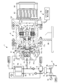
- the power generation system 1 of the present embodiment includes a fuel system, an air system, and an exhaust gas system, and a fuel supply line is provided on the fuel pole 2a (anode) side of SOFC2 which is a fuel cell.
- the fuel gas is introduced via L1
- the air boosted by the compressor 3a of the MGT3 is introduced to the air electrode 2b (anode) side of SOFC2 via the air supply line L2 and the air blower 4. .
- anode off gas of SOFC2 is boosted by the recirculation blower 5 (blower) on the recirculation line L3 and returned to the fuel supply line L1 side, and is recirculated to SOFC2.
- the balance of the anode off gas and the exhaust gas from the air electrode 2b of SOFC2 (hereinafter referred to as cathode off gas) are supplied to the combustor 6, and the combustion gas from the combustor 6 is sent to the gas turbine 3b of the MGT3, so that the MGT3
- the compressor 3a and the generator 3c are driven.
- a gas blower 8 for sending the rest of the anode off gas to the combustor 6 is provided on the upstream side of the combustor 6, and the combustion gas discharged from the combustor 6 and the compressor 3a of the MGT 3 are provided on the downstream side of the combustor 6.
- a heat exchanger 9 for exchanging heat with the air sent from the air supply line L2 is provided. Further, a gas flow rate control valve (not shown) or the like is provided on the upstream side of each of the air blower 4, the gas blower 8, and the recirculation blower 5.
- the fuel gas supplied to the SOFC 2 and the fuel gas supplied to the combustor 6 are, for example, natural gas, city gas, hydrogen and carbon monoxide, methane and other hydrocarbon gases, or carbonaceous raw materials (coal and carbonaceous materials), respectively. It is manufactured from coal, etc.) by a gasification facility, and is prepared so that the calorific value is substantially constant. Further, depending on the operating temperature of SOFC2 (for example, about 700 ° C. to 1000 ° C.), fuel gas heated to a high temperature is supplied to the fuel electrode 2a of SOFC2.
- the fuel gas supplied to the fuel electrode 2a side of the SOFC2 merges with the anode off gas boosted by the recirculation blower 5, for example, water vapor of about 30% to 50% by volume and hydrocarbon gas of the fuel. It becomes a high-temperature hydrogen-rich gas obtained by reforming and reacting with, and becomes a state containing hydrogen (H 2 ), carbon monoxide (CO) and lower hydrocarbon (for example, methane (CH 4)).
- the oxidizing gas supplied to SOFC2 is a gas containing approximately 15% to 30% of oxygen, for example, air, but in addition to air, a mixed gas of combustion exhaust gas and air, a mixed gas of oxygen and air, and the like can be used. (Hereinafter, the oxidizing gas supplied to SOFC2 is also simply referred to as air).
- a predetermined oxidation reaction (2H 2 + 2O) is performed between the steam-reformed high-temperature hydrogen-rich gas and the oxide ion (O 2-) in the electrolyte 2c of SOFC2.
- 2- ⁇ 2H 2 O + 4e - ⁇ (1)) occurs on the other hand
- a predetermined reduction reaction (O 2 + ) is performed between oxygen (O 2 ) in the air supplied by boosting the pressure and electrons given from the fuel electrode 2a side via an external circuit. 4e - ⁇ 2O 2- ⁇ (2 )) may occur.
- fuel (H 2 ) and oxygen (O 2 ) can be chemically reacted to generate electricity, and water (H 2 O) can be generated.
- the DC power output by SOFC2 is converted into 3-phase AC power by, for example, the inverter 7, and boosted by the transformer together with the 3-phase AC power from the generator 3c of MGT3. Then, a part of the three-phase AC power from SOFC2 and MGT3 is also supplied to the accessories of SOFC2 and MGT3.
- the DC power output by SOFC2 can be used as it is.
- Recycle blower 5 shown in FIGS. 1 and 2 high-temperature humidified by water produced by the power generation of SOFC2 (H 2 O), for example, so that can be recycled to 750 ° C. of about anode off in SOFC2, within a predetermined range It is possible to blow air at the air volume and static pressure of.
- SOFC2 H 2 O
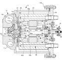
- the recirculation blower 5 is a centrifugal compression type blower that boosts and blows high-temperature anode-off gas discharged from the fuel electrode 2a of SOFC2 (fuel cell), and blows air from the first casing 11. It includes a second casing 12, an impeller 13, a rotating shaft 14, a motor 15, a purge gas introducing means 16, and the like.
- the first casing 11 is integrally fitted with the scroll casing portion 11s for introducing the anode off gas into the gas passage 11c extending from the suction port 11a on the central side to the scroll passage 11b around the central side, and the scroll casing portion 11s on the rear side. It is configured to include a back plate collar member 11p, which is fixed and defines a storage space for the impeller 13 in the gas passage 11c.
- the back plate collar member 11p includes a back plate portion 11d facing the back surface of the impeller 13 and a cylindrical portion 11f forming a shaft hole 11e that opens in the center of the back plate portion 11d. It has a support portion 11g fixed to the tip portion on the inner peripheral side of the second casing 12 with a bolt 17b, and the rotating shaft 14 penetrates the inside of the shaft hole 11e.
- the back plate collar member 11p is a member having a smaller thermal conductivity than the second casing 12, and at least the back plate portion 11d is a substantially plate-shaped heat insulating portion located on the back surface side of the impeller 13, specifically. It constitutes a substantially annular plate-shaped heat insulating portion having an annular stepped surface facing both the outer peripheral surface on the back surface side and the back surface of the impeller 13.
- the back plate portion 11d and the cylindrical portion 11f of the back plate collar member 11p are each airtight located in the vicinity of the shaft hole 11e, and the back plate portion 11d of the back plate collar member 11p has a predetermined gap on the back surface of the impeller 13.
- the cylindrical portion 11f is an airtight cylindrical wall surface portion that forms a shaft hole 11e.
- the scroll casing portion 11s is fastened to the second casing 12 by a plurality of bolts 17c via a fastening flange 11j welded so as to project to the back surface side of the outer peripheral portion thereof. It is also conceivable to provide a heat insulating layer in the annular space 18 formed between the back plate collar member 11p and the fastening flange 11j.
- the second casing 12 is a bottomed tubular body having an internal space 21 communicating with the shaft hole 11e of the first casing 11 and supporting the rotating shaft 14 via a pair of bearings 22A and 22B.
- the rear end side (motor case portion) for accommodating the stator 15s of the motor 15 is formed to have a relatively large diameter with respect to the front end side (bearing box portion) for accommodating the 22B.
- the diameter of the rotating shaft 14 is gradually reduced from the impeller 13 side to the motor 15 side, and the impeller 13 and the rotating shaft 14 can be attached to and detached from the front side with respect to the second casing 12.
- the integral rotating element whose rotation balance has been adjusted from the impeller 13 to the rotor 15r can be formed. Together with the back plate collar member 11p, it may be detachable from the front side (left side in the figure) with respect to the second casing 12.
- the second casing 12 is made of copper, for example, and a heat sink 23 having a large cooling area is integrally coupled to a copper rear end cover portion 12r fastened to the rear end, and a cooling fan 24 is mounted on the heat sink 23.
- the impeller 13 is rotatably housed in the first casing 11 while being integrally supported by the tip end side of the rotating shaft 14, and the anode off gas is sucked by the integral rotation with the rotating shaft 14 to boost the pressure so that it can be recirculated. It has a wing shape that can be used.
- the impeller 13 has a shape in which a plurality of blades 13a are twisted three-dimensionally in the drawing, but the shape is not limited to a specific shape, and any known centrifugal compression type may be used. ..
- the hub back surface portion 13b of the impeller 13 is preferably hollow so as to reduce the cross-sectional area that contributes to heat transfer.
- the rotating shaft 14 is rotatably inserted into the shaft hole 11e of the first casing 11, and fits into the large diameter portion 14a welded to the hub back surface portion 13b of the impeller 13 and the inner rings of the pair of bearings 22A and 22B. It has a medium-diameter portion 14b that is supported while being supported, and a small-diameter portion 14c that penetrates the rotation center portion of the motor 15 and is integrally connected to the rotor 15r.
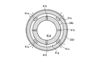
- the rotating shaft 14 has a purge gas passage 41 (a purge gas passage 41) that opens on the bearings 22A and 22B side of the back plate portion 11d (insulation portion) of the back plate collar member 11p and on the outer peripheral surface near the rear end of the shaft hole 11e. A part of the purge gas passage) is formed.
- the purge gas passage 41 creates a gap between the rotor 15r and the stator 15s around the rotating shaft 14 when the purge gas from the purge gas introducing means 16 is supplied from the rear motor 15 side into the internal space 21 of the second casing 12.
- the path of the purge gas In addition to the path of the purge gas (annular gap; hereinafter also referred to as the bearing route) that passes through the inside of the bearings 22A and 22B and reaches the gas storage chamber 31, the path of the purge gas also passes inside the rotating shaft 14 (hereinafter, also referred to as the bearing route). , Also referred to as a shaft hole route), and the supply pressure of the purge gas can be introduced to the shaft hole 11e side in front of the bearings 22A and 22B.
- the support portion 11g of the back plate collar member 11p fastened to the second casing 12 is an airtight low-temperature side wall surface portion located in the vicinity of the plurality of front end side openings 41a of the purge gas passage 41.
- the rotating shaft 14 may be made of the same material.
- a Fe—Ni—Cr alloy or a Ni—Cr—Co alloy can be adopted, or a dense silicon carbide (SiC) or silicon nitride (Si3N4) having a porosity of 10% or less can be used.
- ceramics such as Sialon (SiAlON) can be used.
- the motor 15 is an electric rotary drive means for driving the rotary shaft 14 from the rear end side, for example, a three-phase motor, and has a known stator 15s and a rotor 15r.
- the arrangement of windings, yokes, magnets, etc. in the motor 15 is not limited to a specific mode.
- the purge gas introducing means 16 introduces a gas having a pressure higher than that in the shaft hole 11e of the first casing 11 into the internal space 21 of the second casing 12 as a purge gas for removing the anode off gas from the internal space 21 side.
- the purge gas is introduced into the internal space 21 of the second casing 12, the inflow of the anode off gas from the gas passage 11c side of the first casing 11 into the shaft hole 11e is suppressed.
- the purge gas introducing means 16 is the internal space of the second casing 12 so that the shaft hole 11e of the first casing 11 is always in a gastight sealed state.
- the purge gas is constantly introduced into the 21 and the purge gas can be constantly introduced to the front side of the bearings 22A and 22B through the axial passage 41c described later in the rotating shaft 14.
- the purge gas introduction means 16 may change the purge gas introduction amount per unit time, for example, according to the rotation speed [rpm] of the impeller 13 corresponding to the operating load of the SOFC 2.
- the purge gas introducing means 16 is a purge gas having a predetermined pressure capable of removing residual gas (air at the time of initial operation) on the shaft hole 11e side of at least one bearing 22A of the internal space 21 of the second casing 12.
- fuel gas can be filled in the internal space 21 on the shaft hole 11e side of at least one bearing 22A, here in the entire internal space 21, and the purge gas pressure in the internal space 21 can be applied to the shaft hole 11e.
- the pressure inside and inside the gas passage 11c can be maintained higher than the pressure on the back side of the impeller 13.
- the purge gas introducing means 16 may supply the purge gas at a substantially constant pressure, or may supply the purge gas at a pressure that is variably set stepwise or a pressure that is continuously variably controlled.
- the purge gas introduction means 16 depends on the fuel supply source for extracting a part of the fuel gas from the supply path, the rotation speed [rpm] of the impeller 13, and the pressure in the internal space 21. It includes an introduction control valve capable of adjusting the purge gas pressure, a purge gas introduction passage 42 formed in the rear end cover portion 12r of the second casing 12, an airtight pipe and a joint (not shown), and the like.
- the purge gas introduction passage 42 and the above-mentioned airtight pipes and the like constitute the rest of the purge gas passages located on the upstream side of the purge gas passages 41 and the like (bearing route and shaft hole route) of the two inner and outer paths of the rotating shaft 14.
- the purge gas pressure that opposes the pressure in the shaft hole 11e and the pressure on the back side of the impeller 13 in the gas passage 11c is the detection result of operating conditions such as the rotation speed [rpm] of the impeller 13 and the pressure in the internal space 21 (
- the ventilation target gas introduced into the gas passage 11c and boosted is the anode off gas in which the exhaust gas of the working gas SOFC2 is discharged from the fuel electrode 2a side, and rotates in the internal space 21 of the second casing 12.
- the purge gas introduced into the shaft hole 11e side through the two inner and outer paths of the shaft 14 contains the fuel component of SOFC2.
- the purge gas which is a dry seal gas, may be a nitrogen gas or other dry seal gas that does not contain the fuel component of the fuel cell.
- the purge gas referred to in the present invention is not limited to the fuel gas, and may be another gas such as nitrogen gas or air.
- the blower referred to in the present invention is not limited to the recirculation blower 5, and the target gas is air.
- the air blower 4 may be a gas blower 4 or a gas blower 8 in which the target gas is an anode off gas, or a gas other than the high temperature gas used for the fuel cell may be boosted and blown.
- the target gas referred to in the present invention means a gas having an arbitrary temperature to be blown, but in the present embodiment, a gas heated to a temperature higher than room temperature, for example, a gas heated to about several hundred degrees Celsius. It is a hot gas.
- annular gas storage chamber 31 surrounding the rotating shaft 14 is defined on the rear end side of the shaft hole 11e by a plurality of members including the back plate collar member 11p, the rotating shaft 14 and the bearing 22A.
- the purge gas passage 41 communicates with the gas storage chamber 31.
- a thin-walled cylindrical gap passage 32 having a smaller radial gap dimension than the annular gas storage chamber 31 is provided. It is formed.
- a thin plate-shaped gap 33 that spreads in a direction substantially orthogonal to the thin-walled cylindrical gap passage 32 and bends in a crank shape on the radial outer side is formed. ing.
- the purge gas passes through the gap passage 32 around the rotating shaft 14 in the shaft hole 11e and is within the predetermined flow rate range on the gas passage 11c side of the first casing 11.
- the above-mentioned purge gas pressure is set so that the gas flows in at.
- the tip-side opening 41a of the purge gas passage 41 opens on the front side of the bearing 22A and on the rear end side in the shaft hole 11e, for example, between the large-diameter portion 14a and the medium-diameter portion 14b on the tip-side of the rotating shaft 14.
- the other portion of the purge gas passage 41 following the front end side opening 41a extends radially and axially rearward of the rotating shaft 14.
- the one end side portion of the purge gas passage 41 has a diameter such that the tip side opening 41a opens at a plurality of places on the stepped outer peripheral surface 14d between the large diameter portion 14a and the medium diameter portion 14b of the rotating shaft 14.
- the plurality of radial passages 41b extend in the radial direction from the collecting passage 41d located at the center of the large diameter portion 14a of the rotating shaft 14, and one axial passage 41c extends from the collecting passage 41d to the medium diameter portion 14b. And, it penetrates the axial center portion of the small diameter portion 14c and opens on the rear end surface 14r of the rotating shaft 14.
- the purge gas is supplied to the periphery of the rotating shaft 14 and the purge gas passage 41 in the rotating shaft 14 in the internal space 21 by the supply pressure of the purge gas from the purge gas introducing means 16, and is in front of the bearing 22A.
- Purge gas is supplied to the annular gas storage chamber 31 on the side through a plurality of paths, and purge gas having a predetermined pressure or more is supplied into the shaft hole 11e leading to the gap 33 on the back surface side of the impeller 13.
- the purge gas is urged in the outward radiation direction by centrifugal force as the plurality of radial passages 41b of the purge gas passage 41 rotate, and the purge gas is sucked into the purge gas passage 41. Is promoted, and purge gas having a predetermined pressure or more is more reliably supplied into the shaft hole 11e leading to the gap 33 on the back surface side of the impeller 13.
- a small-diameter cooling passage 41e having a small cross-sectional area may be formed.
- the axial passage 41c on the other end side of the purge gas passage 41 is on a surface extending in the radial direction of the rotating shaft 14 on the rear end side of the rotating shaft 14 from the bearing 22A, for example, on the rear end surface 14r, on the tip side of the rotating shaft 14. It is opened so as to be located on the inner side (rotation center side) in the radial direction from the stepped outer peripheral surface 14d of the above.
- the axial passage 41c of the purge gas passage 41 is opened to a small diameter at the center of the rear end surface 14r of the rotating shaft 14, but for example, the opening diameter of the other end is larger than the intermediate portion of the purge gas passage 41.
- a tapered surface having a larger diameter toward the rear side may be formed on the inner peripheral portion of the rear end of the rotating shaft 14.
- the bearings 22A and 22B are, for example, angular contact ball bearings in which an appropriate amount of grease is sealed, and are supported by the second casing 12 via support rings 25A and 25B on the outer ring side, respectively.
- the recirculation blower 5 is used in the power generation system 1 equipped with the SOFC2 as a blower for blowing high-temperature gas, usually, 1) the shaft seal of the rotating shaft 14 of the impeller 13 with respect to the shaft hole 11e is completely gas tight. 2) Since the power generation system 1 may be used as a distributed power source in remote areas, use only the power source supplied from the system itself, and 3) a distributed power source for general households and small-scale apartments. The recirculation blower 5 is required to be compact, etc.
- the internal space 21 of the second casing 12 is passed through two paths inside and outside the rotating shaft 14 of the impeller 13, and is inside the gas storage chamber 31 on the front side.
- High pressure purge gas is introduced by the purge gas introduction means 16. Therefore, the anode off gas introduced into the first casing 11 of the recirculation blower 5 can enter the shaft hole 11e on the back side of the impeller 13 to store the gas on the front side adjacent to the shaft hole 11e (annular gap). It can be suppressed by the high-pressure purge gas in the chamber 31.
- the pressure of the purge gas is constantly applied from the inside of the shaft hole 11e. Can be maintained at high pressure. Therefore, it is more effectively suppressed that the anode off gas on the gas passage 11c side of the first casing 11 flows into the shaft hole 11e or into the internal space 21 of the second casing 12. Further, even when the bearing 22A is cooled to the dew point (for example, 70 ° C. to 80 ° C.) or lower, the humidified anode off gas does not enter the shaft hole 11e, so that dew condensation in the vicinity of the bearing 22A is effectively suppressed. Therefore, the elution of grease is effectively suppressed.
- the dew point for example, 70 ° C. to 80 ° C.
- the recirculation blower 5 has a simple structure, and the conventional problem that miniaturization and cost reduction become difficult is solved.
- the purge gas containing the fuel component of SOFC2 flows at a predetermined flow rate to the gas passage side of the first casing through the gap passage 32 around the rotating shaft 14 in the shaft hole 11e, and merges with the anode off gas.
- the humidified anode off gas in the casing 11 is surely prevented from entering the internal space 21 of the second casing 12 through the shaft hole 11e, and the anode off gas recirculated to the SOFC 2 is contaminated by the purge gas.
- the thin-walled cylindrical gap passage 32 in the shaft hole 11e, the annular thin plate-shaped gap 33 extending on the back side of the impeller 13, and the like are formed on the back plate collar member 11p, the impeller 13, and the rotating shaft 14. Since it is formed on an airtight wall surface, the dry gas sealing function of the shaft hole 11e can be sufficiently ensured. Further, since the back plate collar member 11p has a heat insulating function and the heat conduction area from the impeller 13 to the rotating shaft 14 is suppressed to be small, the heat transfer to the bearing 22A can be suppressed more effectively.
- the second casing 12 and the support rings 25A and 25B are each made of a material having a large thermal conductivity, effective heat removal from the bearings 22A and 22B to the second casing 12 side becomes possible, and the bearing 22A , The elution of grease from 22B is effectively suppressed, and stable bearing performance can be ensured.
- annular gas storage chamber 31 in which the purge gas passage 41 opens is defined on the rear end side of the shaft hole 11e, and the airtight cylindrical wall surface portion of the back plate collar member 11p and the rotating shaft 14 are formed.
- a gap passage 32 having a smaller radial gap dimension than the annular gas storage chamber 31 is formed between them. Therefore, the air in the gas storage chamber 31 where the bearing 22A is exposed on the rear end side of the shaft hole 11e at the initial stage of operation can be quickly replaced with the purge gas, and the gas storage chamber 31 can be reliably filled with the purge gas. ..
- the purge gas introduction means 16 supplies the purge gas at a predetermined pressure to the gas storage chamber 31 through the two internal and external paths of the rotary shaft 14 of the internal space 21, and promotes the introduction of the purge gas of the shaft hole route according to the rotation speed of the impeller 13.
- the residual gas in the machine is constantly replaced with a purge gas having a suitable flow rate.
- concerns such as elution of lubricant from the bearing 22A due to dew condensation of water vapor can be eliminated, and the dry gas sealing performance of the shaft hole 11e by the purge gas can be improved regardless of the pressure fluctuation of the anode off gas on the impeller 13 side due to the load fluctuation. It will be possible to secure stability.
- the purge gas passage 41 is opened on the outer peripheral surface on the tip end side of the rotating shaft 14 on the rear end side of the shaft hole 11e and on the shaft hole 11e side of the bearing 22A, whereas the purge gas.
- the rear end of the passage 41 is open near the center of the rear end surface 14r of the rotating shaft 14. Therefore, when the rotating shaft 14 rotates, on the tip side of the bearing 22A, the purge gas is urged in the outward radiation direction by centrifugal force as the radial passage 41b of the purge gas passage 41 rotates, and the annular gas storage chamber The inside of 31 is quickly filled, and the suction of purge gas into the purge gas passage 41 is promoted.
- the purge gas pressure acting in the shaft hole 11e can be maintained at a required pressure regardless of the change in the rotation speed of the impeller 13. Further, the purge gas flows in one direction from the rear side to the front side toward the annular gas storage chamber 31, so that the residual gas in the internal space 21 of the second casing 12 is surely replaced with the purge gas.
- the recirculation blower 5 of the present embodiment regardless of the operating state, it is possible to reliably prevent the humidified high-temperature anode-off gas from entering the shaft hole 11e side, and the size and cost are reduced. It will be easy to reduce.
- FIG. 4 shows a blower according to a second embodiment of the present invention.
- a substantially disk-shaped heat insulating wall 37 adjacent to the back plate collar member 11p and the second casing A substantially cylindrical heat insulating cylinder wall 38 surrounding the heat insulating cylinder 12, a substantially annular plate-shaped mounting plate 12f interposed between the second casing 12 and the heat insulating wall 37, and a support cylinder 39 surrounding the heat insulating cylinder wall 38 are provided.
- the second casing 12 has a relatively vertically long (long axis small diameter) casing structure in which the outer peripheral surface thereof is not exposed to the external environment.
- the heat insulating cylinder wall 38 is made of, for example, a ceramic fiber, and a predetermined pressure of purge gas is introduced into the heat insulating cylinder wall 38 from the outer purge gas passage 12p formed on the rear end cover portion 12r side of the second casing 12. , The situation where the hot and humid anode off gas invades into the second casing 12 from the gas passage 11c side around the back plate portion 11d of the first casing 11 and condenses is effectively avoided.
- the rotating shaft 34 that rotatably supports the impeller 13 does not gradually decrease in diameter from the front end side to the rear end side as in the rotating shaft 14 of the first embodiment, but is a shaft between the bearings 22A and 22B.
- the large diameter portion 34a having the maximum diameter is formed in the central portion, the pair of medium diameter portions 34b supported by the bearings 22A and 22B on both sides thereof have substantially the same diameter, and the small diameter portions 34c and 34e on both outer sides have smaller diameters. ing.
- One medium diameter portion 34b on the tip side is inserted into the shaft hole 11e, and the impeller 13 is fastened and fixed to one small diameter portion 34c on the tip side.
- annular gas storage chamber 31 surrounding the rotating shaft 34 is defined by a plurality of members including the back plate collar member 11p, the rotating shaft 34, and the bearing 22A. Most of the gas storage chamber 31 is located on the outer side in the radial direction from the thin-walled cylindrical gap passage 32 in the shaft hole 11e.
- the motor 35 that rotationally drives the impeller 13 via the rotating shaft 34 has a vertically long rotor 35r and a stator 35s, respectively, as compared with the motor 15 in the first embodiment.
- the arrangement of windings, yokes, magnets, etc. in the motor 35 is not limited to a specific form as in the motor 15 in the first embodiment.
- the electric wire of the motor 35 is airtightly drawn to the outside.
- a hermetic connector 45 for connection, a temperature sensor 46 for detecting the bearing temperature and the motor temperature in the second casing 12, and the like are provided.
- FIG. 5 shows a blower according to a third embodiment of the present invention.
- the heat insulating wall 37 of the above, a substantially cylindrical heat insulating cylinder wall 38 surrounding the second casing 12, and a support cylinder 39 surrounding the heat insulating cylinder wall 38 are provided, the second casing 12 has a relatively short axis and a large diameter. It has become. Further, the support cylinder 39 is supported by a fixed support base 36.
- the rotating shaft 34 that rotatably supports the impeller 13 has a maximum diameter at the central portion between the bearings 22A and 22B, and is substantially the same at the portion supported by the bearings 22A and 22B, as in the second embodiment. It is the diameter.
- a plurality of folded cooling passages 43 composed of the horizontal passages 43c connecting them are formed, and the collecting pipes 52 and the hoses 53, 54 and the like connecting these cooling passages 43 to the supply source side of the external cooling medium are formed. It is provided. Then, a cooling medium such as a cooling liquid can be passed through the folded cooling passage 43 to cool the second casing 12.
- the purge gas introduction means 16 mounts a purge gas introduction pipe 47 extending in the direction of the motor rotation axis by opening the center of the rear end cover portion 12r of the second casing 12, and passes through the purge gas introduction pipe 47 into the internal space 21. It is configured to introduce purge gas. Further, a hermetic connector 48 or the like for airtightly pulling out and connecting the wiring of the motor 35 to the outside is mounted on the outer end side of the purge gas introduction pipe 47.
- the recirculation blower 5 of the present embodiment is adapted to boost the high temperature anode off gas discharged from the fuel electrode 2a of the SOFC 2 and blow it.
- the back plate collar member 11p and the mounting plate 12f made of a ceramic fiber or the like are placed on the back side of the first casing 11 for accommodating the impeller 13.
- the heat insulating wall 37 integrated with the heat insulating wall 37 is integrally connected to the second casing 12 by a plurality of bolts 17b fitted in the heat insulating wall 37.
- the first casing 11 and the support cylinder 39 are integrally connected to the second casing 12 that houses the motor 35 via a plurality of bolts 17d fastened to the rear end cover portion 12r. ..
- the heat insulating wall 37 is a substantially plate-like body located on the back surface side of the impeller 13, and the rotating shaft 34 penetrates the circular central portion thereof.
- the rotating shaft 34 that rotatably supports the impeller 13 is a large-diameter portion 34a having the maximum diameter on one side portion between the bearings 22A and 22B and close to the bearing 22A, and the motor 35 is located on the other side portion 34e. While the rotor 35r is integrally mounted, the inner and outer middle diameter portions 34b of the bearings 22A and 22B have substantially the same diameter and are rotatably supported by the second casing 12 via the bearings 22A and 22B. ing. Further, the small diameter portion 34c on the front end side of the rotating shaft 34 is integrally connected to the impeller 13.
- the rotor 35r of the motor 35 is supported by both holdings with respect to the second casing 12 via the bearings 22A and 22B.
- the resonance of the impeller 13 and the rotating shaft 34 (rotating portion) in a wide rotation speed range up to a high rotation speed (for example, 100,000 rpm) can be effectively avoided.
- the rotating shaft 34 has an axial purge gas passage 41 for introducing the purge gas through the shaft to the shaft hole 11e side from the bearings 22A and 22B in the internal space 21, in addition to the purge gas path of the bearing route around the rotating shaft 34.
- a part of the purge gas passage 41 is formed so as to open in the radial direction toward the inner peripheral surface side of the bearing 22A on one side close to the impeller 13.
- a part of the purge gas passage 41 located on the front side of the rotating shaft 34 near the impeller 13 in the axial direction is a first groove portion that opens concavely in the radial direction toward the inner ring 22ir of the bearing 22A, for example. It has an annular groove portion 41g extending in the circumferential direction and a plurality of vertical groove-shaped second groove portions 41a extending from the first groove portion 41g toward the shaft hole 11e, and the plurality of second groove portions 41a. Are opened on the outer peripheral surface of the rotating shaft 34 exposed between the heat insulating portion 37 and the bearing 22A at equal angles of 90 degrees, for example.
- a part of the purge gas passage 41 is formed on a plurality of radial passages 41b penetrating in the radial direction of the rotating shaft 34 so as to open on the inner bottom surface side of the annular groove portion 41g, and on the inner end side of the plurality of radial passages 41b. It is configured to include a gathering passage 41d connected at a predetermined angular interval, and the gathering passage 41d is communicatively connected to an axial passage 41c extending to the rear side of the gathering passage 41d on the rear side in the axial direction thereof.
- the arrangement angle positions are 45 with respect to the plurality of second groove portions 41a, respectively. °
- the purge gas supplied in the radial direction from the collecting passage 41d of the purge gas passage 41 through the plurality of radial passages 41b is the entire circumference on the inner peripheral surface side with respect to the inner ring 22ir of the bearing 22A.
- the inner ring 22ir can be cooled while in direct contact with the air.
- the arrangement angle positions of the plurality of radial passages 41b are 0 °, 90 °, 180 °, and 270 °
- the arrangement angle positions of the plurality of second groove portions 41a are 45 °, 135 °, and so on. It is 225 ° and 315 °.
- a purge gas introduction pipe 47 extending in the direction of the motor rotation axis by opening the center of the rear end cover portion 12r of the second casing 12 is attached, and details are not shown, but for example, a purge gas introduction pipe.
- a purge gas introducing means 16 for introducing purge gas into the internal space 21 is provided through a purge gas passage penetrating the pipe wall of 47 or the like. Then, the purge gas (for example, fuel gas at room temperature) is supplied to the internal space 21 of the second casing 12 by the purge gas introduction means 16, and the purge gas is introduced into the gas storage chamber 31 through a plurality of paths inside and outside the rotating shaft 34.
- a predetermined flow rate effective for cooling the bearing 22A for example, 1 L (liter) -30 L / min.
- the supply pressure of the purge gas described above is set to the extent that it can flow in.
- a hermetic connector 48 or the like for airtightly pulling out and connecting the wiring of the motor 35 to the outside is mounted on the outer end side of the purge gas introduction pipe 47.
- the bearing 22B on the rear side is on the outer ring side supported by the second casing 12, for example, by a core float-shaped support ring 25B in which a lubricant is applied between the O-rings while exteriorizing a plurality of O-rings.
- a core float-shaped support ring 25B in which a lubricant is applied between the O-rings while exteriorizing a plurality of O-rings.
- the support ring 25A that supports the outer ring of the bearing 22A is abutted in the axial direction with respect to the substantially annular plate-shaped mounting plate 12f so as to restrict the forward movement of the bearing 22A, and the substantially annular plate-shaped mounting is performed. It is prevented from rotating by a positioning pin or the like embedded in the plate 12f.
- the rotating shaft 34 pivotally positions the large diameter portion 34a and the other side portion 34e, which are one side portions between the bearings 22A and 22B, by the bearings 22A and 22B, and rotatably supports the rotating shaft 34 in a centered state. It is supposed to be done.
- a plurality of vertical groove-shaped second groove portions 41a which are openings on the front end side of the purge gas passage 41, are on the front side of the bearing 22A and on the rear end side of the shaft hole 11e, and are on the rotating shaft 34.
- the annular groove portion 41g which is open on the outer peripheral surface of the medium diameter portion 34b located on the tip side and is connected to the second groove portion 41a, has a constant groove width near the center of the axial length region of the bearing 22A.
- the rotation shaft 34 is open in the outward radiation direction over the entire circumferential direction.
- the plurality of radial passages 41b communicating with the annular groove portion 41g are connected to the axial passage 41c on the rear side in the axial direction via the collecting passage 41d.
- the purge gas introducing means 16 operates, and when the purge gas is supplied to the internal space 21 of the second casing 12 at a supply pressure corresponding to the rotation speed of the motor 35, the inside and outside of the rotating shaft 34 A purge gas having a predetermined pressure or more is surely introduced into the shaft hole 11e leading to the gap 33 on the back surface side of the impeller 13 and the gas storage chamber 31 through the plurality of paths.
- the purge gas introduced into the purge gas passage 41 is supplied between the shaft hole 11e and the bearing 22A while directly cooling the vicinity of the center of the axial length region of the bearing 22A. Further, the gas inside the machine is continuously replaced by the purge gas, and the purge gas having a predetermined pressure is introduced on the right side of FIG. 1 of the shaft hole 11e, so that the anode off gas is boosted according to the rotation speed of the impeller 13. An effective back pressure is generated to counter the invasion into the shaft hole 11e, and the invasion of the hot and humid anode off-gas into the machine is effectively suppressed. Further, in the present embodiment, since the purge gas can be a fuel gas, the purge gas can flow from the shaft hole 11e to the gas passage 11c side of the first casing 11 at a flow rate effective for cooling the bearing 22A.
- FIG. 9 shows a compact high-speed blower according to a fifth embodiment of the present invention.
- the recirculation blower 5 of the present embodiment is adapted to boost the high temperature anode off gas discharged from the fuel electrode 2a of the SOFC 2 and blow it.
- the back plate collar member 11p and the thick mounting plate 67 are integrally formed on the back surface side of the first casing 11 for accommodating the impeller 13.
- a heat insulating wall 68 is provided and is integrally connected to the second casing 12 by a plurality of bolts 17c.
- the mounting plate 67 of the heat insulating wall 68 surrounds the rotating shaft 34 with a predetermined radial gap between the back plate collar member 11p and the bearing 22A, thereby surrounding the rotating shaft 34 with the shaft hole 11e of the first casing 11 and the bearing.
- An annular gas storage chamber 31 surrounding the rotating shaft 34 is defined between the 22A and the rotating shaft 34.
- the back plate collar member 11p of the heat insulating portion 68 is an airtight wall surface having a thermal conductivity smaller than that of the second casing 12 located at least in the vicinity of the shaft hole 11e. Further, the heat insulating portion 68 forms a shaft hole 11e with a back plate portion 11d (high temperature side wall surface portion) facing the back surface of the impeller 13 with a gap, substantially similar to the back plate collar member 11p in the first embodiment. It has a cylindrical portion 11f (cylindrical wall surface portion) and a support portion 11h (low temperature side wall surface portion) on which the outer ring of the bearing 22A is abutted and supported.
- the heat insulating wall 68 is formed with at least one purge gas introduction passage 61 having an outer end side extending in the radial direction (diameter direction) from the gas storage chamber 31 as an inlet, and an inner end of the purge gas passage 61. Is open in the vicinity of the outer ring abutting portion 11h. Then, the purge gas is introduced directly into the gas storage chamber 31 (without passing through the rotating shaft 34) from the external purge gas introduction means 66 through the purge gas introduction passage 61.
- the purge gas introduction means 66 introduces a gas having a pressure higher than that in the shaft hole 11e of the first casing 11 through the purge gas introduction passage 61 and the gas storage chamber 31. 2 It is introduced inside the casing 12, and when the purge gas is introduced into the gas storage chamber 31, the inflow of hot and humid anode off gas from the gas passage 11c side of the first casing 11 into the shaft hole 11e is suppressed. It has become so.
- the anode is boosted according to the rotation speed of the impeller 13 by introducing the purge gas of a predetermined pressure into the inner side (right side in FIG. 9) of the shaft hole 11e of the first casing 11.
- An effective back pressure is generated to counter the invasion of the off-gas into the shaft hole 11e, and the invasion of the hot and humid anode off-gas into the machine is effectively suppressed.
- the purge gas can flow in from the shaft hole 11e to the gas passage 11c side of the first casing 11.
- the purge gas introduced into the inside of the second casing 12 by the purge gas introduction means 66 via the purge gas introduction passage 61 and the gas storage chamber 31 is in the opposite direction to that of each of the above-described embodiments.
- the gas in the internal space 21 can be constantly replaced while forming a flow.
- the purge gas introduced into the second casing 12 passes through the bearing 22A (a passage that bypasses the bearing 22A, for example, an oblique communication passage that opens at both ends in both the radial and axial directions of the bearing 22A.
- the inside of the internal space 21 flows from the gas storage chamber 31 side to the motor 35 side, passes through a gap such as around the rotor 35r, and is outside the machine from the purge gas passage 62 that also serves as the motor wiring hole of the rear end cover portion 12r. It is designed to be discharged to. Further, at least at the start of use, the purge gas replacement outlet 63 is fully opened until the air in the second casing 12 which is the bearing box is replaced with the purge gas.
- the rotating shaft 34 is provided with a fastening ring 27 with a brim, which is located in the gas storage chamber 31 and fastens and fixes the inner ring of the bearing 22A to the rotating shaft 34.
- the fastening ring 27 effectively guides the flow of the purge gas flowing into the gas storage chamber 31 to the bearing 22A side, and generates an effective back pressure against the intrusion of the anode off gas into the shaft hole 11e described above. Can be done.
- the blower of the present invention has been described as recirculating the anode off gas of the SOFC.
- the blower of the present invention includes a blower for boosting the anode off gas other than the recirculation blower. It can be used as a blower for boosting high temperature cathode off gas. Therefore, the purge gas can be mainly composed of the gas to be blown, or a so-called inert gas such as nitrogen can be used.
- blower of the present invention can be applied to a blower that recirculates a humidified hydrogen gas to a fuel electrode while compressing it in a hydrogen production system using a solid oxide fuel cell (SOEC), and boosts the target gas. It can also be applied to other blowers capable of making the temperature inside the heat treatment furnace and the firing furnace uniform and improving the heating efficiency.
- SOEC solid oxide fuel cell
- the purge gas supplied at a predetermined supply pressure into the internal space 21 of the second casing 12 is the first supply around the rotating shaft 14 or 34 integrally coupled with the impeller 13. It is configured to be supplied to the gas storage chamber 31 through a plurality of routes including a route (bearing route) and a second supply route (shaft hole route) passing through the purge gas passage 41 inside the rotating shaft 14 or 34.
- a route bearing route
- a second supply route shaft hole route
- the purge gas does not pass through the bearings 22A and 22B, but the support pipes 25A and 25B and the bearing box supporting the bearings 22A and 22B. It goes without saying that it is also conceivable to form a vertical groove or a purge gas passage passing through the outer side of the bearings 22A and 22B in the casing 12.
- the present invention can reliably prevent the gas to be blown from entering the shaft hole side, and can provide a blower that can be easily miniaturized and cost-reduced, and is a fuel cell. It is useful for all blowers suitable for boosting the pressure of the gas to be blown from an electrolytic cell or the like.
Landscapes
- Engineering & Computer Science (AREA)
- General Engineering & Computer Science (AREA)
- Mechanical Engineering (AREA)
- Life Sciences & Earth Sciences (AREA)
- Sustainable Development (AREA)
- Chemical Kinetics & Catalysis (AREA)
- Chemical & Material Sciences (AREA)
- Electrochemistry (AREA)
- General Chemical & Material Sciences (AREA)
- Sustainable Energy (AREA)
- Manufacturing & Machinery (AREA)
- Physics & Mathematics (AREA)
- Thermal Sciences (AREA)
- Structures Of Non-Positive Displacement Pumps (AREA)
- Fuel Cell (AREA)
Abstract
Priority Applications (5)
| Application Number | Priority Date | Filing Date | Title |
|---|---|---|---|
| KR1020217035267A KR102588461B1 (ko) | 2020-03-02 | 2021-03-02 | 블로어 |
| US17/594,998 US20220213899A1 (en) | 2020-03-02 | 2021-03-02 | Blower |
| DE112021000028.4T DE112021000028T5 (de) | 2020-03-02 | 2021-03-02 | Gebläse |
| CN202180003228.4A CN113811691A (zh) | 2020-03-02 | 2021-03-02 | 鼓风机 |
| JP2022504402A JP7333536B2 (ja) | 2020-03-02 | 2021-03-02 | ブロワ |
Applications Claiming Priority (2)
| Application Number | Priority Date | Filing Date | Title |
|---|---|---|---|
| JP2020035041 | 2020-03-02 | ||
| JP2020-035041 | 2020-03-02 |
Publications (1)
| Publication Number | Publication Date |
|---|---|
| WO2021177307A1 true WO2021177307A1 (fr) | 2021-09-10 |
Family
ID=77612620
Family Applications (1)
| Application Number | Title | Priority Date | Filing Date |
|---|---|---|---|
| PCT/JP2021/007961 WO2021177307A1 (fr) | 2020-03-02 | 2021-03-02 | Soufflante |
Country Status (6)
| Country | Link |
|---|---|
| US (1) | US20220213899A1 (fr) |
| JP (1) | JP7333536B2 (fr) |
| KR (1) | KR102588461B1 (fr) |
| CN (1) | CN113811691A (fr) |
| DE (1) | DE112021000028T5 (fr) |
| WO (1) | WO2021177307A1 (fr) |
Families Citing this family (2)
| Publication number | Priority date | Publication date | Assignee | Title |
|---|---|---|---|---|
| US11472280B2 (en) * | 2021-01-07 | 2022-10-18 | GM Global Technology Operations LLC | Conical mount with rotating radial snubber assembly |
| KR20230057891A (ko) | 2021-10-22 | 2023-05-02 | 주식회사 엘지에너지솔루션 | 배터리 케이스, 이를 포함하는 배터리 모듈, 배터리 팩 및 자동차, 및 배터리 케이스 제조 방법 |
Citations (2)
| Publication number | Priority date | Publication date | Assignee | Title |
|---|---|---|---|---|
| JPH01249991A (ja) * | 1988-03-31 | 1989-10-05 | Ebara Corp | 高温ガス用ブロワ |
| JPH0729582A (ja) * | 1993-07-12 | 1995-01-31 | Ishikawajima Harima Heavy Ind Co Ltd | 燃料電池発電装置 |
Family Cites Families (16)
| Publication number | Priority date | Publication date | Assignee | Title |
|---|---|---|---|---|
| US2888193A (en) * | 1957-02-14 | 1959-05-26 | Garrett Corp | Motor driven compressor |
| US3220350A (en) * | 1964-09-03 | 1965-11-30 | Crane Co | Motor driven pump |
| JPS5569793A (en) * | 1978-11-20 | 1980-05-26 | Mitsubishi Heavy Ind Ltd | Sealing system for axis of blower for pressure transportation of poisonous gas |
| DE3600126A1 (de) * | 1986-01-04 | 1987-07-16 | Fortuna Werke Maschf Ag | Geblaese zum umwaelzen grosser gasmengen, insbesondere fuer hochleistungs-laser |
| JP2541700B2 (ja) * | 1990-12-21 | 1996-10-09 | 株式会社牧野フライス製作所 | 軸受の潤滑構造 |
| US5549449A (en) * | 1993-07-02 | 1996-08-27 | Wrr Industries, Inc. | Turbomachinery incorporating heat transfer reduction features |
| JPH0953593A (ja) * | 1995-08-09 | 1997-02-25 | Hitachi Ltd | 回転流体機械の軸シール装置 |
| JP2001173591A (ja) * | 1999-12-17 | 2001-06-26 | Shimadzu Corp | 電動ターボ機械 |
| JP4602248B2 (ja) | 2003-02-03 | 2010-12-22 | 株式会社キャップ | 高温ガス送風用ファン |
| JP4725842B2 (ja) * | 2005-06-30 | 2011-07-13 | 日産自動車株式会社 | 高温流体用ファンの回転軸構造 |
| JP2007032670A (ja) | 2005-07-26 | 2007-02-08 | Ntn Corp | 転がり軸受装置 |
| JP5231611B2 (ja) | 2010-10-22 | 2013-07-10 | 株式会社神戸製鋼所 | 圧縮機 |
| JP6049421B2 (ja) | 2012-11-26 | 2016-12-21 | 三菱日立パワーシステムズ株式会社 | 発電システム及び発電システムの運転方法 |
| JP2018135834A (ja) * | 2017-02-23 | 2018-08-30 | トヨタ自動車株式会社 | 気体圧縮装置 |
| JP7043288B2 (ja) | 2018-02-22 | 2022-03-29 | 三菱重工業株式会社 | 複合発電システム、複合発電システムの運転切替方法及び複合発電システムの運転切替プログラム |
| CN112483429A (zh) * | 2019-09-12 | 2021-03-12 | 开利公司 | 离心压缩机和制冷装置 |
-
2021
- 2021-03-02 DE DE112021000028.4T patent/DE112021000028T5/de active Pending
- 2021-03-02 KR KR1020217035267A patent/KR102588461B1/ko active IP Right Grant
- 2021-03-02 JP JP2022504402A patent/JP7333536B2/ja active Active
- 2021-03-02 CN CN202180003228.4A patent/CN113811691A/zh active Pending
- 2021-03-02 US US17/594,998 patent/US20220213899A1/en active Pending
- 2021-03-02 WO PCT/JP2021/007961 patent/WO2021177307A1/fr active Application Filing
Patent Citations (2)
| Publication number | Priority date | Publication date | Assignee | Title |
|---|---|---|---|---|
| JPH01249991A (ja) * | 1988-03-31 | 1989-10-05 | Ebara Corp | 高温ガス用ブロワ |
| JPH0729582A (ja) * | 1993-07-12 | 1995-01-31 | Ishikawajima Harima Heavy Ind Co Ltd | 燃料電池発電装置 |
Also Published As
| Publication number | Publication date |
|---|---|
| DE112021000028T5 (de) | 2022-01-13 |
| KR102588461B1 (ko) | 2023-10-11 |
| JP7333536B2 (ja) | 2023-08-25 |
| CN113811691A (zh) | 2021-12-17 |
| KR20210142194A (ko) | 2021-11-24 |
| JPWO2021177307A1 (fr) | 2021-09-10 |
| US20220213899A1 (en) | 2022-07-07 |
Similar Documents
| Publication | Publication Date | Title |
|---|---|---|
| WO2021177307A1 (fr) | Soufflante | |
| WO2019087869A1 (fr) | Compresseur centrifuge | |
| US7723857B2 (en) | Turbo generator and fuel cell system having the same | |
| JP6599093B2 (ja) | 燃料電池モジュール、これを備えた複合発電システムおよび燃料電池発電部の温度制御方法 | |
| US6830842B2 (en) | Hydrogen purged motor for anode re-circulation blower | |
| JP4602248B2 (ja) | 高温ガス送風用ファン | |
| WO2019087868A1 (fr) | Compresseur centrifuge | |
| JP5001665B2 (ja) | 固体酸化物型燃料電池の高温燃料ガス送風用ファン | |
| JP5992127B2 (ja) | 燃料電池システムのブロア構造 | |
| JP5980144B2 (ja) | 発電システム、発電システムの運転方法、及び制御装置 | |
| JP2014137977A (ja) | 発電システム | |
| JP2014165072A (ja) | 燃料電池発電システム、コンバインド発電システム、運転方法、及び制御装置 | |
| CN117040200A (zh) | 一种用于空压机的电机、空压机和汽车 | |
| KR20110065167A (ko) | 연료전지차량용 공기블로어 | |
| JP2008057440A (ja) | 軸冷却構造を改良した常圧燃焼タービンシステム | |
| RU2325011C1 (ru) | Система топливных элементов | |
| KR102261509B1 (ko) | 고온 기체용 밀폐형 송풍기 | |
| JP2020033875A (ja) | 圧縮装置 | |
| JP4043314B2 (ja) | ガス循環システム及び発電システム及びガス循環用ファン | |
| RU110432U1 (ru) | Центробежный компрессорный агрегат | |
| JP2016207341A (ja) | 燃料電池コージェネレーションシステム | |
| JP2017082795A (ja) | 圧送ユニットおよび圧送ユニットを備える燃料電池装置 | |
| JP2024037420A (ja) | 定置式燃料電池ユニット | |
| JP5931775B2 (ja) | コンバインド発電システム | |
| JP2024520265A (ja) | ガス供給装置 |
Legal Events
| Date | Code | Title | Description |
|---|---|---|---|
| 121 | Ep: the epo has been informed by wipo that ep was designated in this application |
Ref document number: 21764739 Country of ref document: EP Kind code of ref document: A1 |
|
| ENP | Entry into the national phase |
Ref document number: 20217035267 Country of ref document: KR Kind code of ref document: A |
|
| ENP | Entry into the national phase |
Ref document number: 2022504402 Country of ref document: JP Kind code of ref document: A |
|
| 122 | Ep: pct application non-entry in european phase |
Ref document number: 21764739 Country of ref document: EP Kind code of ref document: A1 |