WO2021176652A1 - Dispositif de mesure optique et procédé de mesure optique - Google Patents
Dispositif de mesure optique et procédé de mesure optique Download PDFInfo
- Publication number
- WO2021176652A1 WO2021176652A1 PCT/JP2020/009425 JP2020009425W WO2021176652A1 WO 2021176652 A1 WO2021176652 A1 WO 2021176652A1 JP 2020009425 W JP2020009425 W JP 2020009425W WO 2021176652 A1 WO2021176652 A1 WO 2021176652A1
- Authority
- WO
- WIPO (PCT)
- Prior art keywords
- optical
- light
- signal
- frequency
- doppler shift
- Prior art date
Links
Images


Classifications
-
- G—PHYSICS
- G01—MEASURING; TESTING
- G01S—RADIO DIRECTION-FINDING; RADIO NAVIGATION; DETERMINING DISTANCE OR VELOCITY BY USE OF RADIO WAVES; LOCATING OR PRESENCE-DETECTING BY USE OF THE REFLECTION OR RERADIATION OF RADIO WAVES; ANALOGOUS ARRANGEMENTS USING OTHER WAVES
- G01S17/00—Systems using the reflection or reradiation of electromagnetic waves other than radio waves, e.g. lidar systems
- G01S17/02—Systems using the reflection of electromagnetic waves other than radio waves
- G01S17/50—Systems of measurement based on relative movement of target
- G01S17/58—Velocity or trajectory determination systems; Sense-of-movement determination systems
-
- G—PHYSICS
- G01—MEASURING; TESTING
- G01S—RADIO DIRECTION-FINDING; RADIO NAVIGATION; DETERMINING DISTANCE OR VELOCITY BY USE OF RADIO WAVES; LOCATING OR PRESENCE-DETECTING BY USE OF THE REFLECTION OR RERADIATION OF RADIO WAVES; ANALOGOUS ARRANGEMENTS USING OTHER WAVES
- G01S13/00—Systems using the reflection or reradiation of radio waves, e.g. radar systems; Analogous systems using reflection or reradiation of waves whose nature or wavelength is irrelevant or unspecified
- G01S13/02—Systems using reflection of radio waves, e.g. primary radar systems; Analogous systems
- G01S13/50—Systems of measurement based on relative movement of target
- G01S13/58—Velocity or trajectory determination systems; Sense-of-movement determination systems
- G01S13/583—Velocity or trajectory determination systems; Sense-of-movement determination systems using transmission of continuous unmodulated waves, amplitude-, frequency-, or phase-modulated waves and based upon the Doppler effect resulting from movement of targets
- G01S13/584—Velocity or trajectory determination systems; Sense-of-movement determination systems using transmission of continuous unmodulated waves, amplitude-, frequency-, or phase-modulated waves and based upon the Doppler effect resulting from movement of targets adapted for simultaneous range and velocity measurements
-
- G—PHYSICS
- G01—MEASURING; TESTING
- G01S—RADIO DIRECTION-FINDING; RADIO NAVIGATION; DETERMINING DISTANCE OR VELOCITY BY USE OF RADIO WAVES; LOCATING OR PRESENCE-DETECTING BY USE OF THE REFLECTION OR RERADIATION OF RADIO WAVES; ANALOGOUS ARRANGEMENTS USING OTHER WAVES
- G01S17/00—Systems using the reflection or reradiation of electromagnetic waves other than radio waves, e.g. lidar systems
- G01S17/02—Systems using the reflection of electromagnetic waves other than radio waves
- G01S17/06—Systems determining position data of a target
- G01S17/08—Systems determining position data of a target for measuring distance only
- G01S17/32—Systems determining position data of a target for measuring distance only using transmission of continuous waves, whether amplitude-, frequency-, or phase-modulated, or unmodulated
- G01S17/34—Systems determining position data of a target for measuring distance only using transmission of continuous waves, whether amplitude-, frequency-, or phase-modulated, or unmodulated using transmission of continuous, frequency-modulated waves while heterodyning the received signal, or a signal derived therefrom, with a locally-generated signal related to the contemporaneously transmitted signal
-
- G—PHYSICS
- G01—MEASURING; TESTING
- G01S—RADIO DIRECTION-FINDING; RADIO NAVIGATION; DETERMINING DISTANCE OR VELOCITY BY USE OF RADIO WAVES; LOCATING OR PRESENCE-DETECTING BY USE OF THE REFLECTION OR RERADIATION OF RADIO WAVES; ANALOGOUS ARRANGEMENTS USING OTHER WAVES
- G01S17/00—Systems using the reflection or reradiation of electromagnetic waves other than radio waves, e.g. lidar systems
- G01S17/88—Lidar systems specially adapted for specific applications
- G01S17/89—Lidar systems specially adapted for specific applications for mapping or imaging
- G01S17/894—3D imaging with simultaneous measurement of time-of-flight at a 2D array of receiver pixels, e.g. time-of-flight cameras or flash lidar
Definitions
- the present invention relates to a light measuring device and a light measuring method.
- a light measuring device also called LiDAR (Light Detection and Ringing) that measures the distance to an object using light is known.
- a ToF (Time of Flight) ranging method is generally adopted.
- the ToF distance measurement method is a method of measuring the distance of an object by the time from transmitting an optical pulse to receiving a reflected pulse reflected from the object.
- optical measuring device can acquire the distance of a wide range of objects from a remote distance, it can be used for diagnosis and prediction of deterioration of infrastructure equipment by measuring the strain of bridges, disaster prevention measures and disaster prediction by measuring the strain of mountain slopes, etc. It's being used.
- the optical measuring device can detect and identify obstacles and suspicious objects in a wide range even in the dark, it is also used for security and monitoring such as airport monitoring. Furthermore, optical measuring devices are beginning to attract attention as sensors for automatic driving.
- a measuring device such as a radar device can measure the relative velocity of an object as well as the distance to the object (see, for example, Patent Documents 1 to 3).
- an object of the present disclosure is to provide an optical measuring device and an optical measuring method capable of measuring the relative velocity of an object by using the ranging light for ToF ranging.
- the optical measuring device includes an optical transmitting means for transmitting distance measuring light for ToF (Time of Flight) distance measurement and light reception for receiving reflected light reflected from a measurement object by the transmitted distance measuring light.
- distance measurement light for ToF (Time of Frequency) distance measurement is transmitted, reflected light reflected from the measurement object by the transmitted distance measurement light is received, and the received reflected light is received.
- the Doppler shift amount of the frequency of the reflected light is calculated based on the phase change amount of the above, and the relative speed of the measurement object is calculated based on the calculated Doppler shift amount.
- an optical measuring device and an optical measuring method capable of measuring the relative velocity of an object using the ranging light for ToF ranging.
- FIG. 1 It is a figure for demonstrating the distance measurement principle of the ToF system. It is a block diagram which shows the outline of the optical measuring apparatus which concerns on embodiment. It is a block diagram which shows the outline of the optical measuring apparatus which concerns on embodiment. It is a timing chart for demonstrating the outline of the light measurement method which concerns on embodiment. It is a flowchart which shows the light measurement method which concerns on Embodiment 1. FIG. It is a timing chart which shows the light measurement method which concerns on Embodiment 1.
- FIG. It is a block diagram which shows the structural example of the optical measuring apparatus which concerns on Embodiment 1.
- FIG. 5 is a frequency spectrum diagram of an optical signal in the optical measurement method according to the second embodiment. It is a block diagram which shows the structural example of the optical measuring apparatus which concerns on Embodiment 2.
- FIG. 5 is a frequency spectrum diagram of an optical signal in the optical measurement method according to the third embodiment. It is a block diagram which shows the structural example of the optical measuring apparatus which concerns on Embodiment 3. It is a timing chart which shows the transmission signal which concerns on Embodiment 3. It is a figure which shows the phase vector of the transmission signal which concerns on Embodiment 3.
- FIG. 1 It is a figure which shows the phase vector of the transmission signal which concerns on Embodiment 3. It is a figure which shows the phase vector of the transmission signal which concerns on Embodiment 3. It is a block diagram which shows the structural example of the transmission side of the optical measuring apparatus which concerns on Embodiment 3.
- FIG. It is a timing chart which shows the received signal which concerns on Embodiment 3. It is a timing chart which shows the received signal which concerns on Embodiment 3. It is a timing chart which shows the example of the optical distance measuring method which concerns on Embodiment 3. It is a timing chart which shows the example of the optical distance measuring method which concerns on Embodiment 3. It is a timing chart which shows the example of the optical distance measuring method which concerns on Embodiment 3. It is a timing chart which shows the example of the optical distance measuring method which concerns on Embodiment 3.
- FIG. 1 shows the distance measurement principle of the ToF distance measurement method.
- the optical measuring device transmits the ranging light including the transmitted light pulse, receives the reflected light reflected from the measurement object, and transmits the transmission time and the reflection of the transmitted light pulse.
- the distance R from the optical measuring device to the object to be measured is measured based on the arrival time (reception time) of the received light pulse contained in the light.
- the optical measuring device transmits, for example, a transmitted optical pulse having a pulse width Tw with a pulse period Tp.
- the pulse period and pulse width are set according to the measurement application, the performance of the optical measuring device, and the like.
- the pulse width Tw is several tens of ns.
- the distance R can be obtained by the following equation (1).
- C is the speed of light
- the return delay time Td is a delay time of about 6.6 ns / m.
- the light intensities of the received light pulse (received light signal) and the transmitted light pulse (transmitted light signal) are shown to be about the same, but in an actual measurement environment, the received light is shown.
- the intensity of the pulse is attenuated more than the intensity of the transmitted light pulse.
- the optical measuring device can measure the distance to the object to be measured by adopting the ToF distance measuring method. Further, in the optical measuring device, by measuring the distance of each measurement point included in a predetermined measurement range (scan range) by the ToF distance measurement method, three-dimensional point group data including the distance of each measurement point is generated. , It becomes possible to grasp the three-dimensional structure of the measurement object within the measurement range.
- the ToF distance measurement method is a method for measuring the distance to the last, it is not possible to directly acquire information other than the distance information, especially the relative velocity. Therefore, the inventor has examined a method of measuring the relative velocity of the object to be measured as well as the distance to the object to be measured in the ToF distance measuring type optical measuring device.
- the inventor found that the following merits can be obtained by acquiring the relative velocity information of the object to be measured. That is, if it is possible to detect whether or not the measurement object is stationary (whether or not it is moving), it can be used for various applications.
- relative speed information can be used for speed detection applications such as speed violation automatic control devices that automatically control vehicle speed violations.
- the relative velocity information can be used for intruder detection by extracting only the point cloud data of the moving measurement point from the point cloud data of the measurement range.
- Relative velocity information can be used.
- the inventor has found that the following problems occur when the relative velocity information is simply obtained by using the ToF distance measurement method. That is, as a simple method, a method of performing ToF distance measurement a plurality of times and obtaining a relative velocity from the plurality of measurement results can be considered. Specifically, the relative velocity is obtained from the fluctuation of the distance information measured at a plurality of timings. Then, since the relative velocity information cannot be obtained by one distance measuring operation, it takes time to acquire the relative velocity. Further, in order to obtain the relative velocities of all the measurement points for the point cloud data including a plurality of distance information, a high-speed distance measurement operation is required.
- the optical measuring device 10 includes an optical transmitting unit 11, an optical receiving unit 12, a Doppler shift amount calculating unit 13, a relative speed calculating unit 14, and a distance calculating unit 15. Further, as shown in FIG. 3, the optical measuring device 10 may include only an optical transmitting unit 11, an optical receiving unit 12, a Doppler shift amount calculating unit 13, and a relative speed calculating unit 14.
- the optical transmission unit 11 transmits distance measurement light including an optical pulse (transmission light pulse) for ToF distance measurement.
- the light receiving unit 12 receives the reflected light reflected from the measurement object by the distance measuring light transmitted by the light transmitting unit 11.
- the Doppler shift amount calculation unit 13 calculates the Doppler shift amount of the light pulse based on the frequency of the light pulse (received light pulse) included in the reflected light received by the light reception unit 12. For example, the Doppler shift amount is calculated based on the phase change amount of the received light pulse (reflected light).
- the relative velocity calculation unit 14 calculates the relative velocity of the object to be measured based on the Doppler shift amount calculated by the Doppler shift amount calculation unit 13.
- the distance calculation unit 15 calculates the distance from the optical measuring device 10 to the object to be measured based on the time difference between the optical pulse transmitted by the optical transmitting unit 11 and the optical pulse received by the optical receiving unit 12.
- FIG. 4 shows a transmitted light signal and a received light signal in the optical measuring device 10.
- the optical measuring device 10 transmits a transmitted light pulse pt having an optical frequency of f1.
- the frequency of the transmission light source (reference light) is f0
- the frequency offset is foffset
- f1 f0 + foffset.
- the optical measuring device 10 receives the received light pulse pr0 having the same optical frequency f1 as the transmitted light pulse pt when the object to be measured is a stationary object, and transmits when the object to be measured is a moving object.
- the received optical pulse pr1 having an optical frequency (f1 + fshift) shifted by a Doppler shift amount (Doppler shift frequency fshift) from the optical frequency f1 of the optical pulse pt is received.
- the relative speed of the object to be measured is calculated by obtaining the Doppler shift amount of the received light pulse (received light signal).
- the Doppler shift amount (fsift) can be expressed by the following equation (2) when the object to be measured approaches the optical measuring device, and is expressed by the following equation (3) when the object to be measured moves away from the optical measuring device. be able to. From these equations, the relative velocity can be obtained based on the Doppler shift amount.
- C is the speed of light and v is the relative speed.
- the distance to the object to be measured is obtained by, for example, the return delay time Td from the time T10 when the transmitted light pulse pt is transmitted to the time T11 when the received light pulse pr0 or pr1 is received.
- the times T10 and T11, which are the reference for obtaining the distance, are not limited to the heads of the transmitted light pulse and the received light pulse (optical signal).
- the relative velocity of the object to be measured can be obtained by transmitting the ranging light including the optical pulse for ToF ranging and obtaining the Doppler shift amount of the frequency of the light pulse included in the received reflected light.
- the optical pulse for ToF distance measurement is used, it is possible to obtain the relative velocity of the measurement target as well as the distance to the measurement target. Further, the measurement accuracy can be improved by obtaining the Doppler shift amount based on the phase change amount of the received optical pulse.
- the phase of the received light pulse is detected by optical heterodyne detection, and the Doppler shift amount is calculated from the detected phase change amount.
- the transmitting side of the optical measuring device generates a transmitted light pulse having a predetermined frequency offset (S101), and transmits the generated transmitted light pulse as distance measurement signal light (S101). S102).
- the optical signal of the transmission light source (reference light source) having a frequency of f0 is modulated (phase modulation) so that a predetermined positive frequency offset offfset is added to obtain the optical frequency (f0 + offset).
- the frequency offset factoret is not particularly limited, but is, for example, 100 MHz to 200 MHz.
- the receiving side of the optical measuring device receives the reflected light from the measurement object (S103), and calculates the distance of the measurement object based on the time difference between the transmitted light pulse and the received light pulse. (S104).
- the distance of the object to be measured is obtained from the return delay time Td from the time T10 when the transmitted light pulse pt is transmitted to the time T11 when the received light pulse pr is received.
- the receiving side of the optical measuring device calculates the Doppler shift amount from the phase change amount of the received light pulse (S105), and calculates the relative velocity of the measurement object based on the calculated Doppler shift amount. (S106).
- the received light pulse pr having an optical frequency (f0 + foffset + fshift) shifted by the Doppler shift frequency fshift from the transmitted light pulse pt is received, as in FIG.
- the phase of this received light pulse pr increases monotonically according to its frequency.
- the slope ⁇ 0 of the phase ⁇ 0 when the object to be measured is a stationary object and the slope ⁇ 1 of the phase ⁇ 1 when the object to be measured is a moving object are different.
- the slope of the phase increase means the frequency (angular frequency)
- the slope ⁇ 1 of the phase ⁇ 1 of the received light pulse received from the moving object is compared with the slope ⁇ 0 of the phase ⁇ 0 of the received light pulse received from the stationary object.
- the Doppler shift amount (fshift) is obtained from the difference in inclination.
- FIG. 7 shows the configuration of the optical measuring device according to the present embodiment.
- the configuration of FIG. 7 is an example, and other configurations may be used as long as the optical ranging method according to the present embodiment can be implemented.
- other coherent optical transmitter / receiver may be used.
- the light measuring device 100 includes a light source device 101, a modulation signal generation unit 102, a light intensity phase modulator 103, an optical transmission unit 104, an optical reception unit 105, and a light source device 106. It includes a coherent IQ optical receiver 107, an ADC 108, a reception pulse detection unit 109, a reception time extraction unit 110, a distance calculation unit 111, a phase detection unit 112, a Doppler shift amount calculation unit 113, and a relative speed calculation unit 114.
- the light source device 101, the modulation signal generation unit 102, and the light intensity phase modulator 103 constitute an optical ranging pulse generation unit (optical pulse generation unit) 120 that generates an optical pulse.
- the optical ranging pulse generation unit 120 and the optical transmission unit 104 form a transmission unit (transmission side) of the optical measurement device 100
- the optical reception unit 105, the light source device 106, the coherent IQ optical receiver 107, the ADC 108, and the reception pulse constitute the reception unit (reception side) of the optical measuring device 100.
- the light source device 101 is a light source device such as a laser that generates a light source r0 (for example, frequency f0) for generating a transmitted light pulse.
- the modulation signal generation unit 102 generates a phase modulation signal m0 for subjecting the transmitted light pulse to a monotonically increasing phase modulation. Further, the modulation signal generation unit 102 outputs the transmission trigger signal Tr at the timing of generating (modulating) the transmission light pulse.
- the light intensity phase modulator 103 generates a transmission light pulse in which the light source r0 is subjected to intensity modulation and phase modulation based on the phase modulation signal m0, and outputs a transmission light signal p0 including the transmission light pulse.
- the light intensity phase modulator 103 generates a transmitted light pulse having a predetermined frequency offset by performing a monotonically increasing phase modulation on the light source r0 based on the phase modulation signal m0 (I, Q).
- the light intensity phase modulator 103 is, for example, an MZ (Mach-Zehnder) type IQ light modulator.
- FIG. 8 shows a configuration example in which the light intensity phase modulator 103 is configured by the MZ type IQ light modulator.
- the light intensity phase modulator 103 includes an arm 202 and an arm 203 which are branch waveguides between the input optical waveguide 201 and the output optical waveguide 204, and the arm 202 and the arm 203 have optical modulation units, respectively.
- the 200a and the optical modulation unit 200b are arranged in parallel.
- the optical modulation unit 200a and the optical modulation unit 200b are MZ type optical modulators.
- the optical modulation unit 200a is a phase modulation unit that performs phase modulation in the in-phase direction.
- the optical modulation unit 200a has a phase modulation electrode 201a, and the positive side or the negative side in the in-phase direction with respect to the input optical signal according to the voltage of the phase modulation signal m0 (I) input to the phase modulation electrode 201a. Is phase-modulated.
- the optical modulation unit 200b is a phase modulation unit that applies phase modulation in the orthogonal direction.
- the optical modulation unit 200b has a phase modulation electrode 201b, and is on the positive side or the negative side in the direction orthogonal to the input optical signal according to the voltage of the phase modulation signal m0 (Q) input to the phase modulation electrode 201b. Is phase-modulated.
- an optical signal modulated in an arbitrary phase can be generated. For example, enter the exp optical signal (r0) of (j2 ⁇ f 10 t), by entering the cos phase modulated signal m0 (Q) of (2 [pi] f 11 t) of the phase modulation signal m0 (I) and sin (2 ⁇ f 11 t) , Exp ⁇ j2 ⁇ (f 10 + f 11 ) t ⁇ optical signal (p0) is output.
- the optical transmission unit 104 transmits a transmission light signal p0 including a transmission light pulse as a ranging signal light.
- the optical transmission unit 104 is a transmission optical system such as a lens, and emits the transmitted light signal p0 as parallel light to the object to be measured.
- the light receiving unit 105 receives the reflected light reflected from the object to be measured, and outputs the received light signal p1 including the received light pulse.
- the light receiving unit 105 is a receiving optical system such as a lens, like the light transmitting unit 104.
- optical transmission / reception block 130 including the optical systems of the optical transmission unit 104 and the optical reception unit 105 is shown in FIG. 7 as an example in which independent optical systems are configured on the transmission side and the reception side, respectively, but the present invention is not limited to this. ..
- transmission / reception may be performed using the same optical system, and the transmission signal and the reception signal may be separated by using a circulator.
- the light source device 106 is a light source device such as a laser that generates a reference light r1 for interfering with the received light signal p1.
- the light source device 106 is the same device as the light source device 101 on the transmitting side, and the reference light r1 is an optical signal having the same frequency (for example, f0) as the light source r0 on the transmitting side. Further, instead of the light source device 106, the light of the light source device 101 on the transmitting side may be branched to be the reference light r1.
- the coherent IQ optical receiver 107 causes the received optical signal p1 including the received optical pulse to interfere with the reference light r1 to generate the IQ received signal m1.
- the IQ reception signal m1 includes a signal having an in-phase component (m1 (I)) and a signal having an orthogonal component (m1 (Q)) with respect to the reference light r1.
- the coherent IQ optical receiver 107 includes an optical interference system 107a and an optical / electric converter 107b.
- the optical interference system 107a causes the received optical signal p1 and the reference light r1 to interfere with each other to generate an interference optical signal p2 including an optical signal p2 (I) having an in-phase component and an optical signal p2 (Q) having an orthogonal component.
- the optical / electric converter 107b photoelectrically converts the in-phase component and the orthogonal component of the interference light signal p2, respectively, to generate the IQ reception signal m1.
- the coherent IQ optical receiver 107 it is possible to use a coherent IQ optical receiver composed of a 90 ° hybrid mixer and a balanced receiver used in general digital coherent optical communication, which is similar to optical communication. In principle, the signal sent from the transmitting side can be demolished on the receiving side.
- the ADC 108 is an AD converter (Analog-to-digital converter) that AD-converts the photoelectrically converted IQ reception signal m1.
- the reception pulse detection unit (optical pulse extraction unit) 109 extracts only the reception light pulse portion of the reception signal based on the light intensity of the AD-converted IQ reception signal m1.
- the reception time extraction unit 110 specifies the reception time (arrival time) of the received light pulse from the rising timing of the signal extracted by the reception pulse detection unit 109.
- the distance calculation unit 111 calculates the distance of the object to be measured from the transmission time of the transmission light pulse and the reception time of the reception light pulse.
- the distance calculation unit 111 calculates the distance of the object to be measured based on the time difference between the time of the transmission trigger signal Tr indicating the transmission timing of the transmission light pulse and the time of the rise timing of the reception light pulse.
- the phase detection unit 112 detects the phase of the received light pulse from the signal extracted by the reception pulse detection unit 109.
- the Doppler shift amount calculation unit 113 calculates the Doppler shift amount of the received light pulse based on the phase of the detected received light pulse.
- the relative velocity calculation unit 114 calculates the relative velocity of the object to be measured based on the calculated Doppler shift amount.
- FIG. 9 shows a specific example of the signal on the transmitting side in the optical measuring device 100 of FIG.
- the light source device 101 on the transmitting side generates a light source r0 having an optical frequency of f0.
- the modulation signal generation unit 102 generates phase modulation signals m0 (I) and m0 (Q) for modulation so that the slope of the phase increases monotonically.
- the phase of the phase modulation signal m0 (I) and the phase of the phase modulation signal m0 (Q) are out of phase by 90 °.
- the phase of the phase modulation signal m0 (Q) signal is 90 ° behind the phase modulation signal m0 (I).
- the phase of the phase modulation signal m0 increases monotonically with time, as shown in FIG. The portion other than the transmitted light pulse pt is extinguished, and the phase is indefinite.
- the phase increases (or increases) monotonically with time, or decreases (or decreases) monotonically with time means that the phase changes with time with respect to the phase of the optical signal of the reference light source r0. It increases (or increases) monotonically, or decreases (or decreases) monotonically over time.
- the transmission light pulse pt as shown in FIG. 9 is generated. Will be generated.
- the generated transmitted optical pulse pt becomes an optical signal whose phase is monotonically increased by the phase modulation signals m0 (I) and m0 (Q), and the frequency of this optical signal is f0 + foffset obtained by adding the frequency offset foffset to the frequency f0 of the reference light. It becomes.
- FIG. 9 shows that the phase modulation signals m0 (I) and m0 (Q) are input to the light modulation units 200a and 200b of the light intensity phase modulator 103 of FIG. 8
- the generated transmitted optical pulse pt becomes an optical signal whose phase is monotonically increased by the phase modulation signals m0 (I) and m0 (Q), and the frequency of this optical signal is f0 + foffset obtained by adding the frequency offset foffset to the frequency f0 of the reference light. It becomes.
- this phase vector is a vector that rotates counterclockwise on the complex plane with time by the phase of the phase modulation signals m0 (I) and m0 (Q), in other words, by the frequency offset (+ frequency).
- the optical transmission unit 104 transmits a transmission light signal p0 including the generated transmission light pulse pt.
- the light intensity of the transmitted light signal p0 has a pulse shape as shown by the broken line on p01 in FIG.
- FIG. 11 and 12 show specific examples of signals on the receiving side in the optical measuring device 100 of FIG. 7.
- FIG. 11 is an example of a received signal when the object to be measured is a stationary object
- FIG. 12 is an example of a received signal when the object to be measured is a moving object.
- the light source device 106 on the receiving side generates the reference light r1 having the same optical frequency f0 as that on the transmitting side.
- the light of the light source device 101 on the transmitting side may be branched to be the reference light r1.
- the optical receiving unit 105 receives the received light signal p1 including the received light pulse pr reflected from the stationary object.
- the signal is the same as that on the transmitting side shown in FIG. That is, the optical frequency of the received optical pulse is f0 + foffset.
- the optical interference system 107a of the coherent IQ optical receiver 107 causes the received optical signal p1 and the reference light r1 to interfere with each other in accordance with the general principle of coherent IQ reception used in digital coherent optical communication to generate the IQ reception signal m1. ..
- the IQ reception signals m1 (I) and m1 (Q) output from the coherent IQ optical receiver 107 have the same waveforms as the phase modulation signals m0 (I) and m0 (Q) on the transmitting side. That is, in the received light pulse pr, the IQ reception signal m1 (Q) is deviated by 90 ° from the IQ reception signal m1 (I), similarly to the transmission light pulse pt.
- the light intensity of the IQ reception signal m1 becomes a pulse waveform of a constant level from time T20 to T21, and the reception pulse detection unit 109 detects a range exceeding a predetermined threshold value to detect time T20.
- the pulse region from to T21 is detected.
- the phase detection unit 112 detects the phase of the IQ reception signal m1 in the range from time T20 to T21 in the detected pulse region.
- the detected phase increases monotonically with time, as on the transmitting side.
- the slope of the phase ⁇ 0 is 2 ⁇ ⁇ foffset.
- the light receiving unit 105 receives the received light signal p1 including the received light pulse pr reflected from the moving object.
- the signal on the transmitting side shown in FIG. 9 is a Doppler-shifted signal. That is, the optical frequency of the received optical pulse is f0 + foffset + fshift.
- the IQ reception signals m1 (I) and m1 (Q) output from the coherent IQ optical receiver 107 have different waveforms from the phase modulation signals m0 (I) and m0 (Q) on the transmitting side.
- the IQ reception signal m1 of offset + fshift whose frequency is higher by fshift than the IQ reception signal m1 of FIG. 11 without Doppler shift is obtained.
- the light intensity of the IQ reception signal m1 becomes a pulse waveform of a constant level from the time T20 to T21 as in FIG. 11, and the reception pulse detection unit 109 detects the pulse region from the time T20 to T21.
- the phase detection unit 112 detects the phase of the IQ reception signal m1 in the range from time T20 to T21 in the detected pulse region.
- the detected phase monotonically increases with a steeper slope than in FIG. As described with reference to FIG. 6, in this case, the slope of the phase ⁇ 1 is 2 ⁇ ⁇ (foffset + fshift).
- the Doppler shift amount calculation unit 113 obtains the difference between the phase gradient ⁇ 0 of the received light pulse without the Doppler shift in FIG. 11 and the phase gradient ⁇ 1 of the received light pulse with the Doppler shift in FIG. Calculate the Doppler shift amount of the pulse. For example, the phase inclination ⁇ 0 of the received light pulse received from a stationary object is measured in advance, and when the phase inclination ⁇ 1 of the received light pulse received from the moving object is measured, the difference between ⁇ 1 and ⁇ 0 is obtained. May be good. Further, the slope of the phase of the transmitted light pulse (transmitted light signal) may be used as ⁇ 0.
- the relative velocity calculation unit 114 calculates the relative velocity of the object to be measured from the above equations (2) and (3) using the calculated Doppler shift amount.
- the relative speed of the measurement object is calculated from the Doppler shift amount of the frequency of the received light pulse received from the measurement object.
- the distance to the object to be measured and the relative speed of the object to be measured can be measured at once.
- the measurement accuracy can be improved by detecting the phase of the received light pulse and calculating the Doppler shift amount based on the detected phase change amount (slope with respect to time). Since the pulse width Tw of the optical pulse of the ToF ranging method is as narrow as several tens of ns, it is difficult to realize the calculation of the Doppler shift amount by the FFT (Fast Fourier Transform) circuit. Even in the FFT circuit, it is possible to calculate the Doppler shift amount with the same accuracy regardless of the circuit scale, but it is necessary to increase the number of FFT measurements (resolution) in order to improve the accuracy. In the present embodiment, by using the phase change amount of the optical pulse, the Doppler shift amount can be calculated with high accuracy with a smaller calculation amount (smaller circuit scale) than that of the FFT circuit.
- FFT Fast Fourier Transform
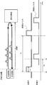
- an optical signal region having a monotonically increasing phase (positive frequency offset) and an optical signal region having a monotonically decreasing phase (positive frequency offset) are defined. Transmit includes transmitting optical pulses.
- FIG. 13 and 14 show the optical measurement method according to the present embodiment
- FIG. 15 shows the frequency spectrum of the optical signal in this optical measurement method.
- transmission is performed by modulation using a positive frequency offset (first frequency offset) and a negative frequency offset (second frequency offset) on the transmitting side of the optical measuring device.
- An optical pulse is generated (S201), and the generated transmitted light pulse is transmitted as a ranging signal light (S202).
- a positive frequency offset is an offset in the positive direction with respect to the frequency of the reference light source
- a negative frequency offset is an offset in the negative direction with respect to the frequency of the reference light source.
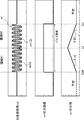
- a positive frequency offset (+ foffset) is applied to the optical signal of the transmission light source having a frequency f0 in the region # 1 (first phase modulation portion) of the first half portion of the transmission light pulse pt. Is modulated so that the phase increases monotonically (changes with the first gradient with respect to time), and in the latter half region # 2 (second phase modulation portion) of the transmitted light pulse pt, a negative frequency offset (-).
- modulation is applied so that the phase decreases monotonically (changes with a second gradient with respect to time).
- the optical frequency of the region # 1 is f0 + foffset
- the optical frequency of the region # 2 is f0-foffset.
- the phase change point c1 is the point at which the phase that monotonically increases due to the optical frequency f0 + foffset is switched to the phase that monotonically decreases due to the optical frequency f0-foffset in the transmitted optical pulse pt.
- the frequency spectrum of the transmitted light pulse pt has a frequency component of foffset on the positive side in the region # 1 and a frequency component of ⁇ foffset on the negative side in the region # 2.
- the receiving side of the optical measuring device receives the reflected light from the measurement object (S203), and sets the phase change point of the received light pulse included in the received reflected light as the received light pulse. (S204), and the distance of the object to be measured is calculated based on the time of the phase change point of the transmitted light pulse and the received light pulse (S205).
- the phase change point c2 in which the phase increase / decrease tendency (slope) of the first half region # 1 and the second half region # 2 of the received light pulse pr is switched is extracted.
- the phase of the region # 1 is monotonically increased by the optical frequency f0 + foffset (+ fshift)
- the phase of the region # 2 is monotonically decreased by the optical frequency f0-foffset (+ fshift)
- the phase is monotonously increased from the monotonous increase. Detect the point where it switches to decrease.
- the distance of the object to be measured is obtained from the return delay time Td from the time T10 at the phase change point c1 of the transmitted light pulse pt to the time T11 at the phase change point c2 of the received light pulse pr.
- the transition between the first half and the second half can be predicted from the phase increment in the first half and the phase decrement in the second half, so that noise and waveform distortion It is possible to suppress the influence of the noise and improve the distance measurement accuracy.
- the Doppler shift amount is calculated from the increase / decrease in the phase of the received light pulse (S206), and the relative velocity of the measurement object is calculated based on the calculated Doppler shift amount. (S207).
- the received light pulse pr having an optical frequency shifted by the Doppler shift amount (fshift) from the transmitted light pulse pt is received. do.
- the frequency spectrum of the received light pulse pr has a frequency on the positive side in the region # 1 and a negative side in the region # 2, similar to the transmission signal.
- the frequency distribution is -foffset.
- the frequency spectrum of the received light pulse pr shifts the signals on the positive side and the negative side by the Doppler shift amount (fshift), respectively. That is, in the region # 1, the frequency component on the positive side is separated from f0 by fshift from the foffset, and in the region # 2, the frequency component on the negative side is closer to f0 than -foffset by fshift.
- the slopes ⁇ 11 and ⁇ 21 of the phases ⁇ 11 and ⁇ 21 are different. That is, the slopes ⁇ 11 and ⁇ 21 of the phases ⁇ 11 and ⁇ 21 of the received light pulses received from the moving object are Doppler-shifted in the region # 1 as compared with the slopes ⁇ 10 and ⁇ 20 of the phases ⁇ 10 and ⁇ 20 of the received light pulses received from the stationary object.
- the slope of increase becomes steeper by the amount, and the slope of decrease becomes gentle by the amount of Doppler shift in region # 2.
- the slope of region # 2 ⁇ 21 2 ⁇ ⁇ ( ⁇ foffset + fshift).
- the Doppler shift amount (fshift) is obtained by collecting the slopes of the regions # 1 and the regions # 2. That is, the Doppler shift amount is obtained by adding the absolute values of the slopes of the phases of the regions # 1 and regions # 2 and dividing by 2 as in the following equation (4). As a result, a more accurate frequency shift amount that does not depend on the offset frequency can be obtained.
- the Doppler shift amount may be calculated in one or each of the area # 1 and the area # 2.
- FIG. 16 shows the configuration of the optical measuring device according to the present embodiment.
- the optical measuring device 100 according to the present embodiment includes the same functional block as that of the first embodiment.
- the detection result of the phase detection unit 112 is supplied to the reception time extraction unit 110 and the Doppler shift amount calculation unit 113, respectively.
- the light intensity phase modulator 103 applies phase modulation to the light source r0 to monotonically increase or decrease based on the phase modulation signal m0 (I, Q), and the transmitted light signal including the transmitted light pulse. Generate p0.
- the light intensity phase modulator 103 is, for example, an MZ type IQ light modulator as shown in FIG. 8, as in the first embodiment.
- the reception time extraction unit (phase change point detection unit) 110 detects the phase change point at which the phase of the received light pulse detected by the phase detection unit 112 switches from monotonically increasing to monotonically decreasing. Extract the time.
- the distance calculation unit 111 calculates the distance of the object to be measured from the time of the phase change point of the transmitted light pulse and the time of the phase change point of the received light pulse.
- the distance calculation unit 111 calculates the distance of the object to be measured based on the time difference between the transmission time of the transmission trigger signal Tr indicating the timing of the phase change point of the transmission light pulse and the reception time of the phase change point of the reception light pulse.
- the Doppler shift amount calculation unit 113 includes the phase change amount of the first half portion and the phase change amount of the second half portion of the received light pulse detected by the phase detection unit 112, and the Doppler shift amount calculation unit 113 includes the Doppler of the received light pulse. Calculate the shift amount.
- FIG. 17 shows a specific example of a signal on the transmitting side in the optical measuring device 100 of FIG.
- the light source device 101 on the transmitting side generates a light source r0 having an optical frequency of f0, as in the first embodiment.
- the modulation signal generation unit 102 generates phase modulation signals m0 (I) and m0 (Q) for modulation so that the phase inclinations of the region # 1 and the region # 2 are different.
- the phase of the phase modulation signal m0 (I) and the phase of the phase modulation signal m0 (Q) are out of phase by 90 °, as in the first embodiment.
- the phase of the phase modulation signal m0 (I) is the same as that of the region # 1, and the phase of the phase modulation signal m0 (Q) is inverted (180 ° deviated) from the region # 1. ..
- phase of the phase modulation signal m0 (Q) is advanced by 90 ° with respect to the phase modulation signal m0 (I). Then, as shown in FIG. 17, the phase of the phase modulation signal m0 increases monotonically with time in the region # 1 and decreases monotonically with time in the region # 2.
- phase modulation signals m0 (I) and m0 (Q) are input to the optical modulation units 200a and 200b of the optical intensity phase modulator 103 of FIG. 8, it is shown in FIG.
- Such a transmitted light pulse pt is generated.
- the portion of the region # 1 of the generated transmitted optical pulse pt becomes an optical signal whose phase is monotonically increased by the phase modulation signals m0 (I) and m0 (Q) as in the first embodiment, and the frequency of this optical signal is
- the frequency f0 of the reference light is added to the frequency offset phaset to obtain f0 + phaset.
- the region # 2 of the transmitted optical pulse pt becomes an optical signal whose phase is monotonically decreased by the phase modulation signals m0 (I) and m0 (Q), and the frequency of this optical signal is frequency offset from the frequency f0 of the reference light. It becomes f0-foffset obtained by subtracting the frequency.
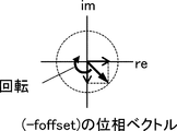
- the phase vector of this region # 2 rotates clockwise with time on the complex plane by the phase of the phase modulation signals m0 (I) and m0 (Q), in other words, by the frequency offset (-foffset). It becomes a vector that rotates to.
- FIG. 19 and 20 show specific examples of signals on the receiving side in the optical measuring device 100 of FIG.
- FIG. 19 is an example of a received signal when the object to be measured is a stationary object
- FIG. 20 is an example of a received signal when the object to be measured is a moving object.
- the optical receiving unit 105 receives the received light signal p1 including the received light pulse pr reflected from the stationary object.
- the signal is the same as that on the transmitting side shown in FIG. That is, the optical frequency of the received light pulse region # 1 is f0 + foffset, and the optical frequency of the region # 2 is f0-foffset.
- the same signal is demodulated on the receiving side as on the transmitting side, based on the principle of the coherent IQ optical receiver used in digital coherent optical communication.
- the IQ reception signals m1 (I) and m1 (Q) output from the coherent IQ optical receiver 107 are the same as the phase modulation signals m0 (I) and m0 (Q) on the transmitting side. It becomes a waveform. That is, in the received light pulse pr, the IQ reception signal m1 (Q) is deviated by 90 ° from the IQ reception signal m1 (I) in the region # 1, and the IQ reception is in the region # 2, as in the transmission light pulse pt. The signal m1 (I) is in phase with the region # 1, and the IQ reception signal m1 (Q) is inverted from the region # 1.
- the IQ reception signal m1 (Q) signal is 90 ° out of phase with the IQ reception signal m1 (I)
- the IQ reception signal m1 (Q) signal is a signal whose phase is advanced by 90 ° with respect to (I).
- the light intensity of the IQ reception signal m1 becomes a pulse waveform of a constant level from time T20 to T21, and the reception pulse detection unit 109 performs a pulse from time T20 to T21 as in the first embodiment. Detect the area.
- the phase detection unit 112 detects the phase of the IQ reception signal m1 in the range from time T20 to T21 in the detected pulse region. The detected phase increases monotonically with time in region # 1 and decreases monotonically with time in region # 2, as on the transmitting side.
- the phase inclination ⁇ 10 of the region # 1 is 2 ⁇ ⁇ foffset
- the phase inclination ⁇ 20 of the region # 2 is -2 ⁇ ⁇ foffset.
- the reception time extraction unit 110 detects the phase change point c2 based on the phase change (slope change) of the IQ reception signal m1.
- the point at which the phase switches from monotonically increasing to monotonically decreasing is detected as the phase change point c2.
- the reception time extraction unit 110 may detect the vertex (maximum value) having the largest phase as the phase change point. For example, when the phase of the region # 1 decreases monotonically and the phase of the region # 2 increases monotonically, the vertex (minimum value) having the smallest phase may be detected as the phase change point.
- an approximate straight line that approximates the slope of the phase of monotonic increase and monotonous decrease may be obtained from the phase sampling data of the region # 1 and the region # 2, and the phase change point may be detected from the intersection of the approximate straight lines.
- the light receiving unit 105 receives the received light signal p1 including the received light pulse pr reflected from the moving object.
- the signal on the transmitting side shown in FIG. 17 is a Doppler-shifted signal. That is, the optical frequency of the received light pulse region # 1 is f0 + foffset + fshift, and the optical frequency of the region # 2 is f0-foffset + fshift.
- the IQ reception signals m1 (I) and m1 (Q) output from the coherent IQ optical receiver 107 are the phase modulation signals m0 (I) and m0 (Q) on the transmitting side and the regions # 1 and # 2.
- Each has a different waveform.
- the IQ reception signal m1 has a frequency higher by fshift than the IQ reception signal m1 in FIG. 19 without Doppler shift
- region # 2 the IQ reception signal in FIG. 19 without Doppler shift is obtained.
- the IQ reception signal m1 has a frequency lower than that of m1 by fshift.
- the reception pulse detection unit 109 detects the pulse region from time T20 to T21.
- the phase detection unit 112 detects the phase of the IQ reception signal m1 in the range from time T20 to T21 in the detected pulse region.
- the detected phase increases monotonically with a steep slope in region # 1 and decreases monotonically with a gentle slope in region # 2, as compared with FIG.
- the phase inclination ⁇ 11 of the region # 1 is 2 ⁇ ⁇ (foffset + fshift)
- the phase inclination ⁇ 21 of the region # 2 is 2 ⁇ ⁇ ( ⁇ foffset + fshift).
- the Doppler shift amount calculation unit 113 obtains the Doppler shift amount by adding the absolute values of the inclinations of the regions # 1 and the regions # 2 and dividing by 2 using the above equation (4). Further, the relative velocity calculation unit 114 uses the calculated Doppler shift amount to calculate the relative velocity of the object to be measured from the above equations (2) and (3) as in the first embodiment.
- phase modulation is performed by the phase that monotonically increases and the phase that monotonically decreases with respect to the first half and the second half of the transmitted light pulse, and the phase change point of the received received light pulse is detected. Measure the distance of the object to be measured. As a result, even if the received light pulse has noise or waveform distortion, the arrival time can be measured with high accuracy, and the distance measurement accuracy can be improved.
- phase modulation to the transmitted light pulse with a phase that increases monotonically and a phase that decreases monotonically, it is possible to predict (approximate) the inclination of the phase of monotonically increasing and the inclination of the phase of monotonically decreasing from the phase information of the received light pulse. Therefore, the distance measurement accuracy can be improved.
- the Doppler shift amount is calculated based on the phase change amount of the first half and the second half of the received light pulse.
- the Doppler shift amount is obtained by adding the absolute values of the slopes of the phases of the first half region and the second half region of the received light pulse and dividing by two.
- the frequency offset can be removed from the calculation of the Doppler shift amount, so that the Doppler shift amount can be obtained accurately without depending on the fluctuation of the frequency offset due to imperfections such as the characteristics of the optical ranging pulse generator. Can be done.
- a transmission light pulse having a monotonically increasing phase (positive frequency offset) and a transmitted light pulse having a monotonically decreasing phase (negative frequency offset) are used.
- the frequency is multiplexed and the multiplexed optical signal is transmitted.
- FIG. 21 shows an optical measurement method according to the present embodiment
- FIG. 22 shows a frequency spectrum of an optical signal in this optical measurement method.
- the transmitting side of the optical measuring device generates a transmitted light pulse having a positive frequency offset and a transmitted light pulse having a negative frequency offset (S301), and two transmitted light pulses.
- the combined wave signal (frequency multiplex signal) obtained by combining the above is transmitted as the ranging signal light (S302).
- an optical signal having an optical frequency of f0 + foffset was transmitted in the region # 1
- an optical signal having an optical frequency of f0-foffset was transmitted in the region # 2.
- each optical signal is time-division-multiplexed.
- an optical signal (optical pulse) having an optical frequency of f0 + foffset and an optical signal (optical pulse) having an optical frequency of f0-foffset are frequency-multiplexed and simultaneously transmitted. ..
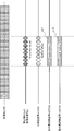
- the frequency spectrum of the transmitted light pulse pt is symmetrical with respect to f0 on the positive side / negative side, has a frequency component of foffset on the positive side, and has a frequency component of -foffset on the negative side.
- the receiving side of the optical measuring device receives the reflected light from the measurement object (S303), and at the transmission time when the distance measurement signal light is transmitted and the reception time when the reflected light is received. Based on this, the distance of the object to be measured is calculated (S304). The distance of the object to be measured is obtained from the time difference between the time at the predetermined position of the transmitted optical signal (combined wave signal) and the time at the predetermined position of the received optical signal.
- a positive frequency offset received light pulse and a negative frequency offset received light pulse are extracted from the received light signal (S305), and the extracted positive frequency offset received light pulse and negative frequency offset received light pulse and negative frequency offset received light pulse.
- the Doppler shift amount is calculated from the phase of the received light pulse of the frequency offset of (S306), and the relative speed of the object to be measured is calculated based on the calculated Doppler shift amount (S307).
- the frequency spectrum of the received optical signal has the intensity of foffset on the positive side and -foffset on the negative side with f0 as the center, as in the transmission signal. It becomes a distribution.
- the frequency component on the positive side (positive frequency component) from f0 is extracted from the received light signal and the frequency component (negative frequency component) on the negative side from f0 is extracted, the frequency component on the positive side (received light pulse) is extracted.
- the frequency component on the positive side (received light pulse) Will be + foffset, and the frequency of the negative frequency component (received light pulse) will be -foffset.
- the frequency spectrum of the received light signal shifts the signals of the positive and negative frequency components by the Doppler shift amount (fshift). That is, the positive frequency component is separated from f0 by fshift from the foffset, and the negative frequency component is closer to f0 by fshift than from -foffset.
- the positive frequency component is extracted from the received optical signal and the negative frequency component is extracted, the frequency of the positive frequency component becomes ifset + fshift, and the frequency of the negative frequency component becomes ⁇ fset + fshift.
- the characteristics of the positive frequency component are the same as the region # 1 of the received light pulse of the second embodiment, and the characteristics of the negative frequency component are the same as the region # 2 of the received light pulse of the second embodiment. Therefore, in the present embodiment, as in the second embodiment, the absolute values of the phase slopes of the positive frequency component (received light pulse) and the negative frequency component (received light pulse) are added and divided by two. Then, find the Doppler shift amount.
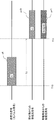
- FIG. 23 shows the configuration of the optical measuring device according to the present embodiment.
- the optical measuring device 100 according to the present embodiment has two optical ranging pulse generating units 120a and 120b, a combiner 121, and a receiving intensity detecting unit as compared with the first and second embodiments. It includes 115, BPF 116a and 116b, and frequency detection units 117a and 117b.
- the reception intensity detection unit 115 is provided instead of the reception pulse detection unit 109 of the first and second embodiments.
- the phase detection unit 112 of the first and second embodiments is not shown, it may be included in the Doppler shift amount calculation unit 113.
- the optical ranging pulse generation unit (first optical pulse generation unit) 120a generates a transmission optical pulse (first optical pulse) having a positive frequency offset
- Part) 120b generates a transmission light pulse (second light pulse) with a negative frequency offset.
- the configurations of the optical ranging pulse generation units 120a and 120b are the same as those in the first and second embodiments.
- the optical intensity phase modulator 103 of the optical ranging pulse generation unit 120a applies phase modulation that monotonically increases to the light source r0 based on the phase modulation signal m0 (I, Q), and transmits an optical signal including a transmitted optical pulse having a frequency of f0 + foffset. Generate p10.
- the optical intensity phase modulator 103 of the optical ranging pulse generation unit 120b applies phase modulation that monotonically decreases to the light source r0 based on the phase modulation signal m0 (I, Q), and transmits the transmission including the transmission optical pulse of the frequency f0-foffset. Generates an optical signal p11.
- the combiner 121 is a wavelength division multiplexing unit that wavelength-multiplexes the transmitted light pulses generated by the optical ranging pulse generation unit 120a and the optical ranging pulse generation unit 120b.
- the combiner 121 includes a transmission light signal p10 including a positive frequency offset transmission light pulse generated by the optical distance measurement pulse generation unit 120a and a negative frequency offset transmission light pulse generated by the optical distance measurement pulse generation unit 120b.
- the transmitted optical signal p11 including the above is combined to generate a combined wave signal p12.
- the reception intensity detection unit 115 extracts only a signal of a predetermined level from the reception signal based on the light intensity of the AD-converted IQ reception signal m1.
- the reception intensity detection unit 115 detects a signal exceeding a predetermined threshold value, similarly to the reception pulse detection unit 109 of the first and second embodiments.
- BPF116a and 116b are bandpass filters that separate signals of positive frequency components and signals of negative frequency components that are wavelength-multiplexed.
- the BPF116a extracts only a positive frequency component from the AD-converted IQ reception signal m1 and generates a positive frequency signal m20 which is a signal of a positive frequency component (received light pulse).
- the BPF116b extracts only the negative frequency component from the AD-converted IQ reception signal m1 and generates the negative frequency signal m21 which is a signal of the negative frequency component (received light pulse).
- the frequency detection units 117a and 117b detect the frequencies of the extracted positive and negative frequency signals.
- the frequency detection unit 117a detects the frequency of the positive frequency signal m20 based on the phase of the positive frequency signal m20 (received light pulse).
- the frequency detection unit 117b detects the frequency of the negative frequency signal m21 based on the phase of the negative frequency signal m21 (received light pulse).
- FIG. 24 shows a specific example of a signal on the transmitting side in the optical measuring device 100 of FIG. 23.
- the light source device 101 on the transmitting side generates a light source r0 having an optical frequency of f0, as in the first and second embodiments.
- the optical ranging pulse generation unit 120a generates a transmission light pulse pt1 having an optical frequency of f0 + foffset by adding a frequency offset offset to the frequency f0 of the reference light, as in the transmission light pulse region # 1 of the second embodiment.
- the optical ranging pulse generation unit 120b generates a transmission light pulse pt2 having an optical frequency of f0-foffset, which is obtained by subtracting the frequency offset offfset from the frequency f0 of the reference light, as in the transmission light pulse region # 2 of the second embodiment.
- the optical signal of + foffset and the optical signal of -foffset can be expressed by the equations (6) and (7), respectively. From the equations (6) and (7), the + foffset optical signal and the -foffset optical signal have the imaginary part inverted and have a conjugate relationship with each other. Therefore, when the + foffset optical signal and the -foffset optical signal are combined, a signal having no imaginary part and only a real part is obtained as shown in the equation (8). Therefore, the combined signal of the + foffset optical signal and the ⁇ foffset optical signal is a signal whose intensity (amplitude) is modulated.
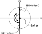
- the + foffset optical signal is a vector that rotates counterclockwise in the phase vector diagram
- the -foffset optical signal is a vector that rotates clockwise in the phase vector diagram.
- each signal repeatedly rotates as shown in FIGS. 25 to 27.
- the vector B1 of the optical signal of + foffset has a positive real part and the imaginary part is positive
- the vector B2 of the optical signal of ⁇ foffset has a positive real part and a negative imaginary part.
- the vectors B1 and B2 are line-symmetrical about the real axis, and the composite wave becomes a signal extending in the positive direction on the real axis.
- the vector B1 has 0 in the real part and the imaginary part is positive
- the vector B2 has 0 in the real part and the imaginary part is negative.
- the vectors B1 and B2 are line-symmetrical about the real axis, the composite wave becomes a 0 signal on the real axis.
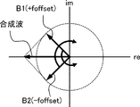
- the vector B1 has a negative real part and a positive imaginary part
- the vector B2 has a negative real part and a negative imaginary part.
- the vectors B1 and B2 are line-symmetrical about the real axis, and the composite wave becomes a signal extending in the negative direction on the real axis.
- the combined wave signal p12 is considered to be an amplitude-modulated signal, and the amplitude-modulated signal is considered to be equivalent to a wavelength division multiplexing signal. Therefore, the transmitting side of the optical measuring device may be configured by an optical amplitude modulator.
- This amplitude modulated signal can be expressed as follows. E c is a carrier signal, E sig is a modulation signal, and E AM is a signal generated by modulation.
- FIG. 28 shows an example in which the transmitting side of the optical measuring device is configured by an optical amplitude modulator.
- the transmitting side of the optical measuring device is provided with an optical ranging pulse generating unit 122 by an optical amplitude modulator instead of the optical ranging pulse generating units 120a and 120b and the combiner 121 of FIG. You may.
- the optical ranging pulse generation unit 122 includes a light source device 101, a modulation signal generation unit 102, and an optical amplitude modulator 123.
- the modulation signal generation unit 102 generates an amplitude modulation signal m3 for giving amplitude modulation of a frequency offset ( ⁇ offset).
- the optical amplitude modulator 123 generates an amplitude-modulated optical signal (combined wave signal p12) in which the light source r0 is amplitude-modulated based on the amplitude-modulated signal m3.
- the optical amplitude modulator 123 is, for example, an MZ type optical modulator.
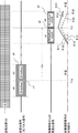
- FIGS. 29 and 30 show specific examples of signals on the receiving side in the optical measuring device 100 of FIG. 23.
- FIG. 29 is an example of a received signal when the object to be measured is a stationary object
- FIG. 30 is an example of a received signal when the object to be measured is a moving object.
- 31 to 33 show an example of the ToF distance measuring method for the signals of FIGS. 29 and 30.
- the light source device 106 on the receiving side generates the reference light r1 having the same optical frequency f0 as the transmitting side, as in the first and second embodiments.
- the optical receiving unit 105 receives the received optical signal p1 having an optical frequency f0 ⁇ offset with the same wavelength division multiplexing as the transmission signal from the object to be measured.
- the same signal as that on the transmitting side is demodulated on the receiving side based on the principle of the coherent IQ optical receiver used in digital coherent optical communication.
- the IQ reception signal m1 (I, Q) output from the coherent IQ optical receiver 107 is frequency-multiplexed by the modulation signals m0 of the optical ranging pulse generation units 120a and 120b on the transmitting side. It becomes a signal with a frequency of ⁇ foffset.
- the reception strength detection unit 115 detects the signal strength of this IQ reception signal, and the reception time extraction unit 110 extracts the reception time based on the signal strength of the detected IQ reception signal.
- the distance calculation unit 111 determines the distance of the object to be measured based on the return delay time Td from the start of transmission of the combined wave signal p12 (transmitted optical signal) to the reception of the received optical signal p1. calculate.
- the modulation signal generation units 102 of the optical ranging pulse generation units 120a and 120b generate the transmission trigger signal Tr at the timing of applying modulation (starting transmission), and the reception time extraction unit 110 generates the reception optical signal p1.
- the reception start time of the IQ reception signal m1 demodulated from the above is extracted as the reception time.
- the transmitted optical signal and the received optical signal are amplitude-modulated signals and do not become pulse-shaped signals. Therefore, the timing for measuring the distance is not limited to FIG. 31.
- the return delay time Td from the time of the first peak of the amplitude modulation of the combined wave signal p12 (the first peak point) to the time of the first peak of the amplitude modulation of the received optical signal p1 Based on this, the distance of the object to be measured may be obtained.
- the combiner 121 generates a transmission trigger signal Tr at the timing of the first peak of the combine signal p12, and the reception time extraction unit 110 demodulates the received optical signal p1 at the beginning of the IQ reception signal m1. Extract the peak time as the reception time.
- the time Td (for example, Td1 to Td8) may be used to determine the distance of the object to be measured. For example, the distance is obtained from the average value of the return delay times Td1 to Td8.
- the combiner 121 generates a transmission trigger signal Tr at the timing of a plurality of peaks of the combine signal p12, and the reception time extraction unit 110 demodulates the received optical signal p1 to a plurality of IQ reception signals m1. Each time of the peak of is extracted as the reception time. Distance measurement accuracy can be improved by measuring the distance using the times of a plurality of peaks.
- a positive frequency signal m20 is extracted from the IQ reception signal m1 having a frequency of ⁇ foffset via the BPF116a, and a negative frequency signal m21 is extracted via the BPF116b.
- the positive frequency signal m20 includes the received light pulse pr1 of frequency + foffset, and the negative frequency signal m21 includes the received light pulse pr2 of frequency ⁇ ffset.
- the optical receiving unit 105 Doppler-shifted the wavelength-multiplexed signal which is the transmission signal from the object to be measured. Receive signal p1. Then, the IQ reception signal m1 (I, Q) becomes a signal of frequency fshift ⁇ foffset, the frequency of the positive frequency signal m20 (received light pulse pr1) via BPF116a becomes fshift + foffset, and the negative frequency signal via BPF116b. The frequency of m21 (received light pulse pr2) is fshift-foffset.
- the frequencies of the positive frequency signal m20 and the negative frequency signal m21 are the same as those of the received light pulse regions # 1 and # 2, respectively, of the second embodiment. Therefore, according to the same principle as in the second embodiment, the Doppler shift amount calculation unit 113 obtains the Doppler shift amount by adding the frequency of the positive frequency signal m20 and the frequency of the negative frequency signal m21 and dividing by two. .. This Doppler shift amount may be obtained from the slope of the phase as in the second embodiment, or may be obtained from the detected frequency.
- the optical pulse having a positive frequency offset and the optical pulse having a negative frequency offset are wavelength-multiplexed and transmitted, and from the frequency of the signal of each frequency component included in the received optical signal.
- the Doppler shift amount is calculated in the same manner as in the second embodiment.
- the Doppler shift amount can be accurately obtained without depending on the fluctuation of the frequency offset due to imperfections such as the characteristics of the optical ranging pulse generation unit.
- the signal of the positive frequency offset and the signal of the negative frequency offset can be transmitted and received with a pulse width twice as large as that of the second embodiment, the frequency (phase) detection accuracy can be improved.
- (Appendix 1) An optical transmission means for transmitting distance measurement light for ToF (Time of Flight) distance measurement, and An optical receiving means for receiving the reflected light reflected from the object to be measured by the transmitted distance measuring light, and A Doppler shift amount calculating means for calculating the Doppler shift amount of the frequency of the reflected light based on the phase change amount of the received reflected light, and A relative speed calculating means for calculating the relative speed of the measurement object based on the calculated Doppler shift amount, and An optical measuring device.
- Appendix 1 An optical transmission means for transmitting distance measurement light for ToF (Time of Flight) distance measurement, and An optical receiving means for receiving the reflected light reflected from the object to be measured by the transmitted distance measuring light, and A Doppler shift amount calculating means for calculating the Doppler shift amount of the frequency of the reflected light based on the phase change amount of the received reflected light, and A relative speed calculating means for calculating the relative speed of the measurement object based on the calculated Doppler shift amount, and An optical measuring device
- the Doppler shift amount calculating means calculates the Doppler shift amount based on the difference between the phase change amount of the reflected light when there is no Doppler shift and the phase change amount of the received reflected light.
- the optical measuring device according to Appendix 1. (Appendix 3) The distance measuring light to be transmitted has a frequency component having a predetermined frequency offset with respect to the frequency of the reference light source.
- the distance measuring light to be transmitted has a frequency component of a first frequency offset that is a positive offset with respect to the frequency of the reference light source and a second frequency component that is a negative offset with respect to the frequency of the reference light source.
- the Doppler shift amount calculating means is based on the phase change amount of the positive frequency component contained in the reflected light and the phase change amount of the negative frequency component contained in the reflected light. Calculate the amount, The optical measuring device according to Appendix 4. (Appendix 6) The Doppler shift amount calculating means calculates the Doppler shift amount based on a value obtained by adding the phase change amount of the frequency component in the positive direction and the phase change amount of the frequency component in the negative direction and dividing by 2. The optical measuring device according to Appendix 5.
- An optical pulse generating means for generating an optical pulse having a phase change point between the first phase modulation portion of the first frequency offset and the second phase modulation portion of the second frequency offset is provided.
- the light transmitting means transmits the ranging light including the generated light pulse.
- the optical measuring device according to any one of Supplementary note 4 to 6.
- a distance calculating means for calculating the distance to the measurement object based on the phase change point of the light pulse included in the transmitted distance measuring light and the phase change point of the light pulse included in the received reflected light is provided. , The optical measuring device according to Appendix 7.
- the optical transmission means transmits a wavelength division multiplexing signal in which the frequency component of the first frequency offset and the frequency component of the second frequency offset are wavelength-multiplexed as the ranging light.
- the optical measuring device according to any one of Supplementary note 4 to 6. (Appendix 10) An optical pulse generating means for generating a first optical pulse having a frequency component of the first frequency offset and a second optical pulse having a frequency component of the second frequency offset.
- a wavelength division multiplexing means for wavelength-multiplexing the generated first and second optical pulses is provided.
- the optical transmission means transmits the ranging light including the first and second wavelength-multiplexed optical pulses.
- the optical measuring device according to Appendix 9.
- An amplitude modulation means for generating an amplitude modulation signal having a frequency component of the first frequency offset and a frequency component of the second frequency offset is provided.
- the optical transmission means transmits the generated amplitude-modulated signal as the ranging light.
- the optical measuring device according to Appendix 9.
- a distance calculating means for calculating the distance to the measurement object based on the first peak point of the transmitted distance measuring light and the first peak point of the received reflected light is provided.
- the optical measuring device according to any one of Appendix 9 to 11.
- the distance calculating means calculates the distance based on the plurality of peak points of the transmitted distance measuring light and the plurality of peak points of the received reflected light.
- the optical measuring device according to Appendix 12.
- the distance calculating means calculates the distance based on the average of the time difference between the plurality of peak points of the transmitted distance measuring light and the plurality of peak points of the received reflected light.
- the optical measuring device according to Appendix 13.
- ToF (Time of Flight) distance measurement light for distance measurement is transmitted, The reflected light reflected from the object to be measured by the transmitted distance measuring light is received, and the reflected light is received.
- the Doppler shift amount of the frequency of the reflected light is calculated based on the phase change amount of the received reflected light. Based on the calculated Doppler shift amount, the relative velocity of the measurement object is calculated. Light measurement method.
- the Doppler shift amount is calculated based on the difference between the phase change amount of the reflected light when there is no Doppler shift and the phase change amount of the received reflected light.
- Optical measuring device 11 Optical transmitting unit 12
- Optical receiving unit 13 Doppler shift amount calculation unit 14
- Distance calculation unit 100 Optical measuring device 101
- Light source device 102 Modulation signal generator 103
- Light intensity phase modulator 104 Light transmitting unit 105
- Optical receiver 106 Light source device 107 Coherent IQ optical receiver 107a
- Optical interference system 107b Optical / electrical converter 108
- Reception pulse detection unit 110 Reception time extraction unit 111
- Distance calculation unit 112 Phase detection unit 113
- Doppler shift amount calculation unit 114 Relative velocity calculation unit 115
- Optical ranging pulse generator 121 Generator 123 Optical amplitude modulator 130
- Optical modulation unit 201 Input optical waveguide 201a, 201b Phase
Abstract
La présente invention concerne un dispositif de mesure optique (10) comprenant : une unité d'émission de lumière (11) qui émet une lumière de mesure pour mesurer un temps de vol (ToF) ; une unité de réception de lumière (12) qui reçoit une lumière de réflexion réfléchie par un objet mesuré en raison de la lumière de mesure émise par l'unité d'émission de lumière (11) ; une unité de calcul de quantité de décalage Doppler (13) qui calcule la quantité de décalage Doppler dans la fréquence de la lumière de réflexion sur la base de la quantité de changement de phase de la lumière de réflexion reçue par l'unité de réception de lumière (12) ; et une unité de calcul de vitesse relative (14) qui calcule la vitesse relative de l'objet mesuré, sur la base de la quantité de décalage Doppler calculée par l'unité de calcul de quantité de décalage Doppler (13).
Priority Applications (3)
| Application Number | Priority Date | Filing Date | Title |
|---|---|---|---|
| JP2022504884A JP7472965B2 (ja) | 2020-03-05 | 2020-03-05 | 光測定装置及び光測定方法 |
| US17/802,998 US20230111392A1 (en) | 2020-03-05 | 2020-03-05 | Optical measurement device and optical measurement method |
| PCT/JP2020/009425 WO2021176652A1 (fr) | 2020-03-05 | 2020-03-05 | Dispositif de mesure optique et procédé de mesure optique |
Applications Claiming Priority (1)
| Application Number | Priority Date | Filing Date | Title |
|---|---|---|---|
| PCT/JP2020/009425 WO2021176652A1 (fr) | 2020-03-05 | 2020-03-05 | Dispositif de mesure optique et procédé de mesure optique |
Publications (1)
| Publication Number | Publication Date |
|---|---|
| WO2021176652A1 true WO2021176652A1 (fr) | 2021-09-10 |
Family
ID=77614215
Family Applications (1)
| Application Number | Title | Priority Date | Filing Date |
|---|---|---|---|
| PCT/JP2020/009425 WO2021176652A1 (fr) | 2020-03-05 | 2020-03-05 | Dispositif de mesure optique et procédé de mesure optique |
Country Status (3)
| Country | Link |
|---|---|
| US (1) | US20230111392A1 (fr) |
| JP (1) | JP7472965B2 (fr) |
| WO (1) | WO2021176652A1 (fr) |
Citations (6)
| Publication number | Priority date | Publication date | Assignee | Title |
|---|---|---|---|---|
| JPS63111489A (ja) * | 1986-10-20 | 1988-05-16 | チャールズ、ピー、ウォン | 基準位置から動いている再帰反射ターゲットの変位を測定する装置 |
| JPH11183616A (ja) * | 1997-12-22 | 1999-07-09 | Mitsubishi Electric Corp | 気象レーダ装置 |
| JP2013190349A (ja) * | 2012-03-14 | 2013-09-26 | Mitsubishi Electric Corp | レーダ装置 |
| JP2014142182A (ja) * | 2013-01-22 | 2014-08-07 | Mitsubishi Electric Corp | レーダ装置およびレーダ信号受信方法 |
| WO2017077612A1 (fr) * | 2015-11-05 | 2017-05-11 | 三菱電機株式会社 | Dispositif de radar à laser |
| WO2019186776A1 (fr) * | 2018-03-28 | 2019-10-03 | 日本電気株式会社 | Dispositif de mesure de distance et procédé de commande associé |
Family Cites Families (7)
| Publication number | Priority date | Publication date | Assignee | Title |
|---|---|---|---|---|
| JP2005010130A (ja) | 2003-06-18 | 2005-01-13 | Kumataka Engineering:Kk | 距離等測定装置 |
| US8144334B2 (en) | 2009-09-29 | 2012-03-27 | The United States Of America As Represented By The Secretary Of The Army | Fiber-optic, digital system for laser Doppler vibrometers (LDVs) |
| WO2015087380A1 (fr) | 2013-12-09 | 2015-06-18 | 三菱電機株式会社 | Dispositif de radar laser |
| JP6157735B2 (ja) | 2014-06-10 | 2017-07-05 | 三菱電機株式会社 | レーザレーダ装置 |
| US10261187B2 (en) | 2016-05-10 | 2019-04-16 | Raytheon Company | Optical phasograms for LADAR vibrometry |
| JP7074311B2 (ja) | 2017-08-30 | 2022-05-24 | 国立研究開発法人産業技術総合研究所 | 光学的距離測定装置および測定方法 |
| WO2020261391A1 (fr) | 2019-06-25 | 2020-12-30 | 三菱電機株式会社 | Dispositif de traitement de signal, procédé de traitement de signal et dispositif radar |
-
2020
- 2020-03-05 US US17/802,998 patent/US20230111392A1/en active Pending
- 2020-03-05 JP JP2022504884A patent/JP7472965B2/ja active Active
- 2020-03-05 WO PCT/JP2020/009425 patent/WO2021176652A1/fr active Application Filing
Patent Citations (6)
| Publication number | Priority date | Publication date | Assignee | Title |
|---|---|---|---|---|
| JPS63111489A (ja) * | 1986-10-20 | 1988-05-16 | チャールズ、ピー、ウォン | 基準位置から動いている再帰反射ターゲットの変位を測定する装置 |
| JPH11183616A (ja) * | 1997-12-22 | 1999-07-09 | Mitsubishi Electric Corp | 気象レーダ装置 |
| JP2013190349A (ja) * | 2012-03-14 | 2013-09-26 | Mitsubishi Electric Corp | レーダ装置 |
| JP2014142182A (ja) * | 2013-01-22 | 2014-08-07 | Mitsubishi Electric Corp | レーダ装置およびレーダ信号受信方法 |
| WO2017077612A1 (fr) * | 2015-11-05 | 2017-05-11 | 三菱電機株式会社 | Dispositif de radar à laser |
| WO2019186776A1 (fr) * | 2018-03-28 | 2019-10-03 | 日本電気株式会社 | Dispositif de mesure de distance et procédé de commande associé |
Also Published As
| Publication number | Publication date |
|---|---|
| US20230111392A1 (en) | 2023-04-13 |
| JPWO2021176652A1 (fr) | 2021-09-10 |
| JP7472965B2 (ja) | 2024-04-23 |
Similar Documents
| Publication | Publication Date | Title |
|---|---|---|
| JP6241283B2 (ja) | レーダ装置および距離速度測定方法 | |
| EP3637134B1 (fr) | Dispositif radar laser | |
| JP7169642B2 (ja) | 光学的測定装置及び測定方法 | |
| US9778362B2 (en) | Relative speed measuring doppler LiDAR | |
| US10564012B2 (en) | Method of improving measurement speed of distributed optical fiber sensor by adopting orthogonal signals and system thereof | |
| KR20210014227A (ko) | 도플러 효과를 조정하기 위한 라이다(lidar) 시스템 | |
| CN114286952A (zh) | 用于光学相位编码的距离检测中的增强的速度分辨率和信噪比的方法和系统 | |
| JP6814180B2 (ja) | 分布光ファイバ振動計測装置および分布光ファイバ振動計測方法 | |
| CA3034765A1 (fr) | Methode de traitement d'un signal issu d'un lidar coherent et systeme lidar associe | |
| JP7426123B2 (ja) | 光学的測定装置及び測定方法 | |
| US20210026018A1 (en) | Operating method for a lidar system, control unit, lidar system, and device | |
| JP4932378B2 (ja) | コヒーレントライダ装置 | |
| JP2010127839A (ja) | レーザレーダ装置 | |
| WO2021176652A1 (fr) | Dispositif de mesure optique et procédé de mesure optique | |
| JP7272327B2 (ja) | 光ファイバ特性測定装置、光ファイバ特性測定プログラム、及び光ファイバ特性測定方法 | |
| CA3100885C (fr) | Methode de mesure des informations sur le champ de vent et lidar sur nacelle | |
| US20190271854A1 (en) | Speckle Mitigation | |
| JP6947294B2 (ja) | 測距装置及び制御方法 | |
| JP7248132B2 (ja) | 光測距装置及び光測距方法 | |
| US20220308192A1 (en) | Techniques for ghosting mitigation in coherent lidar systems using in-phase/quadrature phase (iq) processing | |
| KR20230088809A (ko) | 코히어런트 lidar 시스템들의 다중-타겟 시나리오들에서 피크들을 연관시키기 위한 기법들 | |
| CN117480364A (zh) | 振动测量器及振动测量方法 | |
| JP5202485B2 (ja) | 光線路反射分布測定方法と装置及び光線路設備監視システム | |
| JP7074889B2 (ja) | センサ装置 | |
| Lu et al. | Enhanced Doppler frequency shift measurement and direction discrimination using photonic I/Q detection |
Legal Events
| Date | Code | Title | Description |
|---|---|---|---|
| 121 | Ep: the epo has been informed by wipo that ep was designated in this application |
Ref document number: 20923062 Country of ref document: EP Kind code of ref document: A1 |
|
| ENP | Entry into the national phase |
Ref document number: 2022504884 Country of ref document: JP Kind code of ref document: A |
|
| NENP | Non-entry into the national phase |
Ref country code: DE |
|
| 122 | Ep: pct application non-entry in european phase |
Ref document number: 20923062 Country of ref document: EP Kind code of ref document: A1 |