WO2021176637A1 - 空気調和機 - Google Patents
空気調和機 Download PDFInfo
- Publication number
- WO2021176637A1 WO2021176637A1 PCT/JP2020/009328 JP2020009328W WO2021176637A1 WO 2021176637 A1 WO2021176637 A1 WO 2021176637A1 JP 2020009328 W JP2020009328 W JP 2020009328W WO 2021176637 A1 WO2021176637 A1 WO 2021176637A1
- Authority
- WO
- WIPO (PCT)
- Prior art keywords
- indoor
- predetermined
- unit
- heat exchanger
- control unit
- Prior art date
Links
- 238000000034 method Methods 0.000 claims abstract description 130
- 230000008569 process Effects 0.000 claims abstract description 128
- 238000007710 freezing Methods 0.000 claims abstract description 46
- 230000008014 freezing Effects 0.000 claims abstract description 46
- 239000003507 refrigerant Substances 0.000 claims abstract description 39
- 238000004378 air conditioning Methods 0.000 claims description 42
- 238000012545 processing Methods 0.000 claims description 23
- 238000011282 treatment Methods 0.000 claims description 17
- 230000006870 function Effects 0.000 claims description 13
- 238000012935 Averaging Methods 0.000 claims description 2
- 238000004140 cleaning Methods 0.000 abstract description 87
- 238000005265 energy consumption Methods 0.000 abstract 1
- 238000001816 cooling Methods 0.000 description 16
- 238000010257 thawing Methods 0.000 description 16
- 238000010438 heat treatment Methods 0.000 description 13
- 239000007788 liquid Substances 0.000 description 8
- 238000010586 diagram Methods 0.000 description 5
- 230000000903 blocking effect Effects 0.000 description 4
- 238000004891 communication Methods 0.000 description 4
- 238000001514 detection method Methods 0.000 description 3
- 238000001035 drying Methods 0.000 description 3
- 239000000428 dust Substances 0.000 description 3
- 238000002360 preparation method Methods 0.000 description 3
- 238000005057 refrigeration Methods 0.000 description 3
- 238000012546 transfer Methods 0.000 description 3
- 230000008859 change Effects 0.000 description 2
- 238000009833 condensation Methods 0.000 description 2
- 230000005494 condensation Effects 0.000 description 2
- 230000000694 effects Effects 0.000 description 2
- 230000007246 mechanism Effects 0.000 description 2
- 238000012986 modification Methods 0.000 description 2
- 230000004048 modification Effects 0.000 description 2
- 101100404599 Caenorhabditis elegans nfi-1 gene Proteins 0.000 description 1
- 238000009434 installation Methods 0.000 description 1
- 230000002452 interceptive effect Effects 0.000 description 1
- 238000002844 melting Methods 0.000 description 1
- 230000008018 melting Effects 0.000 description 1
- 238000000926 separation method Methods 0.000 description 1
- XLYOFNOQVPJJNP-UHFFFAOYSA-N water Substances O XLYOFNOQVPJJNP-UHFFFAOYSA-N 0.000 description 1
Images


Classifications
-
- F—MECHANICAL ENGINEERING; LIGHTING; HEATING; WEAPONS; BLASTING
- F24—HEATING; RANGES; VENTILATING
- F24F—AIR-CONDITIONING; AIR-HUMIDIFICATION; VENTILATION; USE OF AIR CURRENTS FOR SCREENING
- F24F11/00—Control or safety arrangements
- F24F11/30—Control or safety arrangements for purposes related to the operation of the system, e.g. for safety or monitoring
- F24F11/41—Defrosting; Preventing freezing
- F24F11/43—Defrosting; Preventing freezing of indoor units
-
- F—MECHANICAL ENGINEERING; LIGHTING; HEATING; WEAPONS; BLASTING
- F24—HEATING; RANGES; VENTILATING
- F24F—AIR-CONDITIONING; AIR-HUMIDIFICATION; VENTILATION; USE OF AIR CURRENTS FOR SCREENING
- F24F11/00—Control or safety arrangements
- F24F11/30—Control or safety arrangements for purposes related to the operation of the system, e.g. for safety or monitoring
- F24F11/46—Improving electric energy efficiency or saving
-
- F—MECHANICAL ENGINEERING; LIGHTING; HEATING; WEAPONS; BLASTING
- F24—HEATING; RANGES; VENTILATING
- F24F—AIR-CONDITIONING; AIR-HUMIDIFICATION; VENTILATION; USE OF AIR CURRENTS FOR SCREENING
- F24F11/00—Control or safety arrangements
- F24F11/30—Control or safety arrangements for purposes related to the operation of the system, e.g. for safety or monitoring
- F24F11/48—Control or safety arrangements for purposes related to the operation of the system, e.g. for safety or monitoring prior to normal operation, e.g. pre-heating or pre-cooling
-
- F—MECHANICAL ENGINEERING; LIGHTING; HEATING; WEAPONS; BLASTING
- F24—HEATING; RANGES; VENTILATING
- F24F—AIR-CONDITIONING; AIR-HUMIDIFICATION; VENTILATION; USE OF AIR CURRENTS FOR SCREENING
- F24F11/00—Control or safety arrangements
- F24F11/50—Control or safety arrangements characterised by user interfaces or communication
- F24F11/54—Control or safety arrangements characterised by user interfaces or communication using one central controller connected to several sub-controllers
-
- F—MECHANICAL ENGINEERING; LIGHTING; HEATING; WEAPONS; BLASTING
- F24—HEATING; RANGES; VENTILATING
- F24F—AIR-CONDITIONING; AIR-HUMIDIFICATION; VENTILATION; USE OF AIR CURRENTS FOR SCREENING
- F24F11/00—Control or safety arrangements
- F24F11/50—Control or safety arrangements characterised by user interfaces or communication
- F24F11/61—Control or safety arrangements characterised by user interfaces or communication using timers
-
- F—MECHANICAL ENGINEERING; LIGHTING; HEATING; WEAPONS; BLASTING
- F24—HEATING; RANGES; VENTILATING
- F24F—AIR-CONDITIONING; AIR-HUMIDIFICATION; VENTILATION; USE OF AIR CURRENTS FOR SCREENING
- F24F11/00—Control or safety arrangements
- F24F11/62—Control or safety arrangements characterised by the type of control or by internal processing, e.g. using fuzzy logic, adaptive control or estimation of values
-
- F—MECHANICAL ENGINEERING; LIGHTING; HEATING; WEAPONS; BLASTING
- F24—HEATING; RANGES; VENTILATING
- F24F—AIR-CONDITIONING; AIR-HUMIDIFICATION; VENTILATION; USE OF AIR CURRENTS FOR SCREENING
- F24F13/00—Details common to, or for air-conditioning, air-humidification, ventilation or use of air currents for screening
- F24F13/22—Means for preventing condensation or evacuating condensate
-
- F—MECHANICAL ENGINEERING; LIGHTING; HEATING; WEAPONS; BLASTING
- F24—HEATING; RANGES; VENTILATING
- F24F—AIR-CONDITIONING; AIR-HUMIDIFICATION; VENTILATION; USE OF AIR CURRENTS FOR SCREENING
- F24F1/00—Room units for air-conditioning, e.g. separate or self-contained units or units receiving primary air from a central station
- F24F1/0007—Indoor units, e.g. fan coil units
- F24F1/0059—Indoor units, e.g. fan coil units characterised by heat exchangers
-
- F—MECHANICAL ENGINEERING; LIGHTING; HEATING; WEAPONS; BLASTING
- F24—HEATING; RANGES; VENTILATING
- F24F—AIR-CONDITIONING; AIR-HUMIDIFICATION; VENTILATION; USE OF AIR CURRENTS FOR SCREENING
- F24F11/00—Control or safety arrangements
- F24F11/50—Control or safety arrangements characterised by user interfaces or communication
- F24F11/56—Remote control
- F24F11/59—Remote control for presetting
-
- Y—GENERAL TAGGING OF NEW TECHNOLOGICAL DEVELOPMENTS; GENERAL TAGGING OF CROSS-SECTIONAL TECHNOLOGIES SPANNING OVER SEVERAL SECTIONS OF THE IPC; TECHNICAL SUBJECTS COVERED BY FORMER USPC CROSS-REFERENCE ART COLLECTIONS [XRACs] AND DIGESTS
- Y02—TECHNOLOGIES OR APPLICATIONS FOR MITIGATION OR ADAPTATION AGAINST CLIMATE CHANGE
- Y02B—CLIMATE CHANGE MITIGATION TECHNOLOGIES RELATED TO BUILDINGS, e.g. HOUSING, HOUSE APPLIANCES OR RELATED END-USER APPLICATIONS
- Y02B30/00—Energy efficient heating, ventilation or air conditioning [HVAC]
- Y02B30/70—Efficient control or regulation technologies, e.g. for control of refrigerant flow, motor or heating
Definitions
- the present invention relates to an air conditioner.
- Patent Document 1 As a technique for cleaning the indoor heat exchanger of an air conditioner, for example, in Patent Document 1, a control device heats the indoor heat exchanger after cooling and frosting the indoor heat exchanger. The cleaning operation for defrosting is described.
- Patent Document 1 describes a cleaning operation of an air conditioner including one outdoor unit and one indoor unit, but a cleaning operation of a multi-type air conditioner including a plurality of indoor units in one system. Is not described. For example, in a multi-type air conditioner, if the cleaning operation is performed individually for each indoor unit that satisfies the start condition of the cleaning operation, the frequency of driving the compressor increases, and as a result, the power consumption of the air conditioner is increased. The amount may also increase.
- a part of the piping (for example, a common part of the piping through which the gas refrigerant flows). ) Is also cooled.
- the cleaning operation is performed individually for each of the plurality of indoor units, the power consumption per unit capacity of the indoor units is increased. In consideration of such a thing, it is desired to save energy in the cleaning operation.
- an object of the present invention is to provide an air conditioner that saves energy in cleaning a plurality of indoor heat exchangers.
- an outdoor unit having a compressor and an outdoor heat exchanger and a plurality of indoor units having an indoor expansion valve and an indoor heat exchanger are connected.
- a refrigerant circuit connected via the above is provided, and at least a control unit for controlling the compressor and a plurality of the indoor expansion valves is provided, and the control unit is a predetermined indoor unit included in the plurality of the indoor units.
- the other indoor units would not start the process until the process of freezing or condensing the indoor heat exchanger was started.
- FIG. 1 is a configuration diagram including a refrigerant circuit Q of the air conditioner 100 according to the first embodiment.
- the flow of the refrigerant in the cooling cycle is indicated by a solid line arrow
- the flow of the refrigerant in the heating cycle is indicated by a broken line arrow.
- the air flow in the vicinity of the outdoor heat exchanger 2 and the four indoor heat exchangers 10 is indicated by white arrows.
- the air conditioner 100 is a device that performs air conditioning such as cooling operation and heating operation.
- air conditioning such as cooling operation and heating operation.
- FIG. 1 as an example, one system of multi-type air conditioner 100 in which one outdoor unit Uo and four indoor units U1, U2, U3, and U4 are predeterminedly connected via piping is used. Shown.
- the air conditioner 100 includes a compressor 1, an outdoor heat exchanger 2, an outdoor fan 3, an outdoor expansion valve 4, a four-way valve 5, an accumulator 6, and an outdoor temperature sensor as devices provided in the outdoor unit Uo. 7 and blocking valves 8 and 9 are provided.
- the compressor 1 is a device that compresses a low-temperature low-pressure gas refrigerant and discharges it as a high-temperature high-pressure gas refrigerant, and includes a compressor motor 1a (see FIG. 3) as a drive source.
- a compressor 1 for example, a scroll type compressor or a rotary type compressor is used.
- the outdoor heat exchanger 2 is a heat exchanger in which heat exchange is performed between the refrigerant passing through the heat transfer tube (not shown) and the outside air sent from the outdoor fan 3.
- One end g1 of the outdoor heat exchanger 2 is connected to the suction side or the discharge side of the compressor 1 by switching the four-way valve 5, and the other end g2 is connected to the liquid side pipe J1.
- the outdoor fan 3 is a fan that sends outside air to the outdoor heat exchanger 2.
- the outdoor fan 3 includes an outdoor fan motor 3a as a drive source, and is installed in the vicinity of the outdoor heat exchanger 2.
- the outdoor expansion valve 4 is an electronic expansion valve that adjusts the flow rate of the refrigerant flowing through the outdoor heat exchanger 2 and reduces the pressure of the refrigerant when the outdoor heat exchanger 2 functions as an evaporator. It is provided in J1.
- the four-way valve 5 is a valve that switches the flow path of the refrigerant to a predetermined value according to the operation mode during air conditioning.
- the accumulator 6 is a shell-shaped member that gas-liquid separates the refrigerant flowing through the four-way valve 5. After gas-liquid separation by the accumulator 6, the gaseous refrigerant is guided to the suction side of the compressor 1.
- the outdoor temperature sensor 7 is a sensor that detects the outdoor temperature, which is the temperature of the outside air, and is installed at a predetermined position of the outdoor unit Uo (in the example of FIG. 1, the air suction side of the outdoor heat exchanger 2). Although not shown in FIG. 1, each sensor for detecting one or more of the discharge pressure, the discharge temperature, the suction pressure, and the suction temperature of the compressor 1 may be appropriately provided.
- the blocking valves 8 and 9 are valves that are opened after the installation of the air conditioner 100 to spread the refrigerant sealed in the outdoor unit Uo throughout the refrigerant circuit Q.
- One blocking valve 8 is provided in the gas side pipe J10, and the other blocking valve 9 is provided in the liquid side pipe J1.
- the air conditioner 100 includes an indoor heat exchanger 10, an indoor fan 11, an indoor expansion valve 12, an indoor temperature sensor 13, an indoor heat exchanger temperature sensor 14, and other devices provided in the indoor unit U1. It has.
- the indoor heat exchanger 10 is a heat exchanger in which heat is exchanged between the refrigerant passing through the heat transfer tube (not shown) and the indoor air (air in the air conditioning room) sent from the indoor fan 11. be.
- One end h1 of the indoor heat exchanger 10 is connected to the gas side pipe J3, and the other end h2 is connected to the liquid side pipe J2.
- the indoor fan 11 is a fan that sends indoor air to the indoor heat exchanger 10.
- the indoor fan 11 has an indoor fan motor 11a as a drive source, and is installed in the vicinity of the indoor heat exchanger 10.
- the indoor expansion valve 12 is an electronic expansion valve that adjusts the flow rate of the refrigerant flowing through the indoor heat exchanger 10 and reduces the pressure of the refrigerant when the indoor heat exchanger 10 functions as an evaporator, and is a pipe on the liquid side. It is provided in J2.
- the indoor temperature sensor 13 is a sensor that detects the temperature of the indoor air, which is the temperature of the air conditioning room. In the example of FIG. 1, the indoor temperature sensor 13 is installed on the air suction side of the indoor heat exchanger 10.
- the indoor heat exchanger temperature sensor 14 is a sensor that detects the temperature of the indoor heat exchanger 10. In the example of FIG. 1, the indoor heat exchanger temperature sensor 14 is installed near the other end h2 of the indoor heat exchanger 10 in the pipe J2.
- the position of the indoor heat exchanger temperature sensor 14 is not limited to the example of FIG. For example, in the pipe J3, the indoor heat exchanger temperature sensor 14 may be installed near one end h1 of the indoor heat exchanger 10. Further, the indoor heat exchanger temperature sensor 14 may be installed directly on the indoor heat exchanger 10.
- the remaining three indoor units U2, U3, and U4 have the same configuration as the indoor unit U1 described above, and thus the description thereof will be omitted.
- the liquid side connection portions K1, K2, and K3 split the refrigerant during the cooling cycle and merge the refrigerant during the heating cycle. For example, during the cooling cycle, the refrigerant flowing through the pipe J1 is sequentially distributed to the four indoor heat exchangers 10 via the liquid side connection portions K1, K2, and K3. ..
- the gas side connection portions K4, K5, and K6 combine the refrigerant during the cooling cycle and divide the refrigerant during the heating cycle. For example, during the cooling cycle, the refrigerants merge from the four indoor heat exchangers 10 through the gas side connection portions K4, K5, and K6 in sequence.
- the refrigerant circulates in a well-known refrigeration cycle (cooling cycle or heating cycle shown in FIG. 1) in the refrigerant circuit Q according to the operation mode at the time of air conditioning.
- a well-known refrigeration cycle cooling cycle or heating cycle shown in FIG. 1
- the refrigerant circulates in sequence through the compressor 1, the outdoor heat exchanger 2 (condenser), the outdoor expansion valve 4, the indoor expansion valve 12, and the indoor heat exchanger 10 (evaporator).
- the refrigerant circulates in sequence through the compressor 1, the indoor heat exchanger 10 (condenser), the indoor expansion valve 12, the outdoor expansion valve 4, and the outdoor heat exchanger 2 (evaporator).
- FIG. 2 is an explanatory diagram showing a connection relationship of each device of the air conditioner 100.
- the air conditioner 100 includes a remote controller 15 and a centralized management device 16 in addition to the above-described configuration.
- the outdoor unit Uo includes an outdoor control circuit 17, while the indoor units U1, U2, U3, and U4 each include an indoor control circuit 18.
- the outdoor control circuit 17 and the indoor control circuit 18 are configured to include electronic circuits such as a CPU (Central Processing Unit), a ROM (Read Only Memory), a RAM (Random Access Memory), and various interfaces. .. Then, the program stored in the ROM is read out and expanded in the RAM, and the CPU executes various processes.
- a CPU Central Processing Unit
- ROM Read Only Memory
- RAM Random Access Memory
- the outdoor control circuit 17 is connected to the outdoor temperature sensor 7 via the wiring m1. Then, the outdoor control circuit 17 calculates the control command value of each device based on the detection value of each sensor including the outdoor temperature sensor 7 and the signal from the remote controller 15.
- the outdoor control circuit 17 is connected to the indoor control circuit 18 via the communication line m3.
- the indoor control circuit 18 is connected to the indoor temperature sensor 13 via the wiring m21, and is also connected to the indoor heat exchanger temperature sensor 14 via the wiring m22. Each of these detected values is transmitted from the indoor control circuit 18 to the outdoor control circuit 17 via the communication line m3. Then, the indoor control circuit 18 predeterminedly controls the indoor fan motor 11a (see FIG. 1) and the indoor expansion valve 12 (see FIG. 1) based on the control command value calculated by the outdoor control circuit 17.
- the four remote controllers 15 are connected via the wiring m4 so as to have a one-to-one correspondence with the indoor control circuits 18 of the four indoor units U1, U2, U3, and U4.
- a plurality of indoor units may be connected to one remote controller 15.
- the remote controller 15 connected to the indoor unit U1 has a function of giving a predetermined control command to the indoor unit U1 by a user operation. Examples of the control command described above include operation / stop of the air conditioner 100, switching of the operation mode, change of the set temperature, air volume, and wind direction, and start of the cleaning process described later. The same applies to the other indoor units U2, U3, and U4.
- the centralized management device 16 is a device that controls the display and settings of the four remote controllers 15, and is connected to the outdoor control circuit 17 via the communication line m5.
- the user operating the centralized management device 16 in a predetermined manner, it is possible to change not only the air conditioning setting but also the display method on the four remote controllers 15.
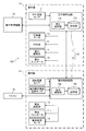
- FIG. 3 is a functional block diagram of the air conditioner 100.
- the outdoor control circuit 17 includes a storage unit 17a and an outdoor control unit 17b.
- the storage unit 17a in addition to a predetermined program and detection values of each sensor, data input from the centralized management device 16 and the like are stored.
- the outdoor control unit 17b controls the compressor motor 1a, the four-way valve 5, the outdoor expansion valve 4, the outdoor fan motor 3a, and the like based on the data stored in the storage unit 17a.
- the indoor control circuit 18 includes a storage unit 18a and an indoor control unit 18b.
- the indoor control unit 18b predeterminedly controls the indoor expansion valve 12, the indoor fan motor 11a, the wind direction plate motor 19, and the like based on the data stored in the storage unit 18a.
- the outdoor control circuit 17 and the indoor control circuit 18 are collectively referred to as “control unit 20”.
- the wind direction plate motor 19 shown in FIG. 3 is a motor that adjusts the wind direction of the air blown into the room by adjusting the angle of the wind direction plate (not shown) of the indoor unit U1.
- a filter (not shown) for collecting dust and dirt is often provided on the air suction side of the indoor heat exchanger 10. However, fine dust and dirt may pass through the filter and adhere to the indoor heat exchanger 10. Therefore, it is desirable to clean the indoor heat exchanger 10 on a regular basis. Therefore, in the first embodiment, after the indoor heat exchanger 10 is frozen (frosted), the indoor heat exchanger 10 is washed by melting the ice and frost of the indoor heat exchanger 10. Such a series of processes is referred to as "cleaning process" of the indoor heat exchanger 10.
- FIG. 4 is a flowchart of processing executed by the control unit of the air conditioner (see FIGS. 1 and 3 as appropriate). Note that FIG. 4 shows a process related to the cleaning process, and omits other processes (normal air conditioning operation, etc.).
- step S101 the control unit 20 determines whether or not all the indoor units U1, U2, U3, and U4 are stopped. When all the indoor units U1, U2, U3, and U4 are stopped (S101: Yes), the process of the control unit 20 proceeds to step S102. On the other hand, in step S101, when there is at least one indoor unit that is performing air conditioning operation (that is, it is not stopped) (S101: No), the process of the control unit 20 returns to "START" (RETURN).
- the operating point of the pressure in the compressor 1 is significantly different between the cleaning process of freezing the indoor heat exchanger 10 and the normal air conditioning operation. Therefore, when all the indoor units U1, U2, U3, and U4 are stopped, the control unit 20 performs a predetermined determination process (next step S102) regarding the cleaning process.
- step S102 the control unit 20 determines whether or not the integrated value of the air-conditioning operation time of the representative indoor unit (predetermined indoor unit) has reached the predetermined value.
- the representative indoor unit may be appropriately changed by operating the centralized management device 16.
- the integrated value of the air conditioning operation time of the representative indoor unit U1 is, for example, the time during which normal air conditioning operation such as cooling operation or heating operation is performed with reference to the end of the previous cleaning process. Is the sum of the values (the sum of the values).
- step S102 when the integrated value of the air-conditioning operation time of the representative indoor unit U1 has reached a predetermined value (S102: Yes), the process of the control unit 20 proceeds to step S103.
- the processing of the control unit 20 returns to "START" (RETURN). Then, the control unit 20 repeats the processes of steps S101 and S102 until the condition of step S102 is satisfied.
- the representative indoor unit U1 and the other indoor units U2, U3, and U4 are not cleaned.
- control unit 20 is the other indoor unit U2 until the predetermined indoor unit U1 included in the plurality of indoor units U1, U2, U3, U4 starts processing such as freezing of the indoor heat exchanger 10.
- the above-mentioned processing (freezing) is not started.
- the driving frequency of the compressor 1 can be reduced, and the power consumption of the air conditioner 100 can be significantly reduced, as compared with the case where the cleaning process is individually performed for each indoor unit.
- do not start the processing such as freezing of the indoor heat exchanger 10 in the other indoor units U2, U3, U4 means that after the previous cleaning treatment in the other indoor units U2, U3, U4 is performed. This means that the control unit 20 has not yet started the current cleaning process on the other indoor units U2, U3, and U4.
- step S103 the control unit 20 executes the cleaning process not only with the representative indoor unit U1 but also with the other indoor units U2, U3, and U4. That is, the control unit 20 causes the representative indoor unit U1 and the other indoor units U2, U3, and U4 to overlap at least a part of the time zone for performing the cleaning process.
- the timing at which the control unit 20 starts the cleaning process in the indoor units U1, U2, U3, and U4 may be substantially the same.
- the timing at which the control unit 20 ends the cleaning process in the indoor units U1, U2, U3, and U4 may be substantially the same.
- step S103 the process of the control unit 20 returns to "START" (RETURN).
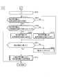
- FIG. 5 is a flowchart of a cleaning process in an air conditioner. That is, FIG. 5 specifically shows the cleaning treatment performed in each of the indoor units U1, U2, U3, and U4 with respect to step S103 of FIG.
- the control unit 20 freezes the indoor heat exchanger 10.
- the control unit 20 causes the indoor heat exchanger 10 to function as an evaporator and frosts the indoor heat exchanger 10.
- the control unit 20 defrosts the indoor heat exchanger 10.
- the control unit 20 causes the indoor heat exchanger 10 to function as a condenser to melt the frost in the indoor heat exchanger 10.
- the dust and dirt of the indoor heat exchanger 10 are washed away by the water accompanying the thawing of the frost.
- step S103c the control unit 20 dries the indoor heat exchanger 10.
- the control unit 20 prohibits the air conditioning operation for a predetermined period from the time of thawing, and dries the indoor heat exchanger 10 by natural convection of air.
- the control unit 20 ends a series of processes related to the cleaning process (END).
- FIG. 6 is a time chart of the cleaning process in the air conditioner (see FIGS. 1 and 3 as appropriate).
- each indoor expansion valve 12 of the indoor units U1, U2, U3, and U4 is described as an “indoor expansion valve”
- each indoor fan 11 is described as an “indoor fan”.
- the air conditioner 100 is stopped at time t0, and the valve body (not shown) of the four-way valve 5 is in the position of the heating cycle.
- the control unit 20 drives the indoor fans 11 of the indoor units U1, U2, U3, and U4 at a predetermined rotation speed Nfi1 at times t1 to t3.
- the control unit 20 drives the outdoor fan 3 at a predetermined rotation speed Nfo1 from the time t2.
- the control unit 20 keeps the outdoor expansion valve 4 in the closed state while driving the outdoor fan 3, and drives the compressor 1 at a relatively low rotation speed Nc2.
- the differential pressure between the high pressure side and the low pressure side of the four-way valve 4 is appropriately adjusted.
- the control unit 20 After performing such a process, the control unit 20 performs a process of freezing the indoor heat exchangers 10 of the indoor units U1, U2, U3, and U4 at times t4 to t5 (S103a in FIG. 5). That is, the control unit 20 switches the four-way valve 5 from the heating cycle to the cooling cycle at time t4. Further, at times t4 to t5, the control unit 20 keeps the outdoor expansion valve 4 open (fully open in the example of FIG. 6), while the indoor expansion valve 12 is narrowed down to a predetermined opening Ei1 and the compressor 1 is set to a predetermined position. It is driven at a rotation speed Nc1.
- the control unit 20 narrows the indoor expansion valves 12 of the indoor units U1, U2, U3, and U4 to a predetermined opening degree Ei1, so that each indoor heat exchanger 10 functions as an evaporator.
- the low-temperature low-pressure refrigerant flows through the indoor heat exchanger 10, and the indoor heat exchanger 10 freezes.
- the control unit 20 keeps the state where the detected value of the indoor heat exchanger temperature sensor 14 (see FIG. 3) is below the freezing point for a predetermined time.
- the control unit 20 drives the outdoor fan 3 at a predetermined rotation speed Nfo1 while stopping each indoor fan 11.
- Nfo1 a predetermined rotation speed
- the control unit 20 may drive the indoor fan 11 at a low speed.
- the control unit 20 After freezing each indoor heat exchanger 10, the control unit 20 drives the compressor 1 at a relatively low rotation speed Nc2 in preparation for thawing of the indoor heat exchanger 10 at times t5 to t6. As a result, the differential pressure between the high pressure side and the low pressure side of the four-way valve 5 is appropriately adjusted. By the way, when the differential pressure on the high pressure side and the low pressure side of the four-way valve 5 is relatively large, as shown in FIG. 6, the control unit 20 decelerates the compressor 1 as a preparation for thawing, but the differential pressure described above. If is too small, the control unit 20 accelerates the compressor 1. Further, the control unit 20 maintains the opening degree of the indoor expansion valve 12 at a predetermined opening degree Ei1 at the time of freezing.
- the control unit 20 switches the four-way valve 5 from the cooling cycle to the heating cycle.
- the four-way valve 5 can be switched while continuing to drive the compressor 1.
- the control unit 20 may temporarily stop the compressor 1, switch the four-way valve 5 from the cooling cycle to the heating cycle, and then thaw the indoor heat exchanger 10. ..
- each indoor heat exchanger 10 time t6 to t7, the control unit 20 narrows the outdoor expansion valve 4 to a predetermined opening Eo1 while opening each indoor expansion valve 12 (in the example of FIG. 6). Fully open).
- the indoor heat exchanger 10 functions as a condenser, and the high-temperature refrigerant flows through the heat transfer tube (not shown) of the indoor heat exchanger 10.
- control unit 20 drives the outdoor fan 3 at a predetermined rotation speed Nfo2 while thawing each indoor heat exchanger 10 (time t6 to t7), while maintaining each indoor fan 11 in a stopped state.
- Nfo2 a predetermined rotation speed
- the control unit 20 may drive the indoor fan 11 at a low speed.
- the control unit 20 dries the indoor heat exchanger 10 for a predetermined time from time t7 (S103c in FIG. 5).
- the control unit 20 stops each device including each indoor fan 11.
- the control unit 20 may prohibit the air conditioning operation based on the operation of the remote controller 15 for a predetermined time from the end of thawing of the indoor heat exchanger 10 (time t7). This prevents cold air from flowing from the indoor units U1, U2, U3, and U4 into the air conditioning chamber, and allows the indoor heat exchanger 10 to be dried by natural convection.
- the control unit 20 uses the other indoor units U1, U2, U3, and U4 until the predetermined indoor unit U1 starts the process of freezing the indoor heat exchanger 10.
- the indoor units U2, U3, and U4 do not start freezing the indoor heat exchanger 10.
- the driving frequency of the compressor 1 can be reduced, and the power consumption of the air conditioner 100 can be significantly reduced, as compared with the case where the cleaning process is individually performed for each indoor unit.
- the indoor heat exchangers 10 are frozen at once, so that the common area of the piping through which the gas refrigerant flows is cooled by the freezing. Can be reduced. Therefore, the power consumption per unit capacity of the indoor units U1, U2, U3, and U4 can be reduced. As described above, according to the first embodiment, it is possible to provide the air conditioner 100 that saves energy in cleaning the plurality of indoor heat exchangers 10.
- the time (total value) required for the cleaning process can be shortened during the predetermined period as compared with the case where the cleaning process is individually performed for each indoor unit.
- the indoor unit can perform air conditioning operation based on the operation of the remote controller 15.
- Second Embodiment For the representative indoor unit U1 and other indoor units U2, U3, and U4, whether or not the cleaning treatment setting is valid, and whether or not the conditions such as the cleaning treatment time zone are satisfied.
- Others configuration of the air conditioner 100, etc .: see FIGS. 1 to 3 are the same as those in the first embodiment. Therefore, a part different from the first embodiment will be described, and a description of the overlapping part will be omitted.
- step S203 is a predetermined value in step S202 (S202: Yes).
- step S202 when the integrated value of the air-conditioning operation time of the representative indoor unit U1 has not reached the predetermined value in step S202 (S202: No), the processing of the control unit 20 returns to "START"("RETURN" in FIG. 7B). ..
- step S203 the control unit 20 determines whether or not the cleaning process setting of the representative indoor unit U1 is valid.
- the cleaning process setting can be enabled / disabled by, for example, the operation of the centralized management device 16 (see FIG. 3) by the administrator (user).
- step S203 when the setting of the cleaning process of the representative indoor unit U1 is enabled (S203: Yes), the process of the control unit 20 proceeds to step S204.
- step S203: No when the setting of the cleaning process of the representative indoor unit U1 is invalid (S203: No), the process of the control unit 20 returns to "START" ("RETURN" in FIG. 7B).
- step S204 the control unit 20 determines whether or not the representative indoor unit U1 satisfies the conditions such as the time zone of the cleaning process.
- the time zone in which the cleaning process is performed the day of the week, the date, and the like can be set by the operation of the centralized management device 16 (see FIG. 3) by the administrator (user).
- step S204 if the representative indoor unit U1 satisfies the conditions such as the cleaning processing time zone (S204: Yes), the processing of the control unit 20 proceeds to step S205.
- the cleaning process is set to be performed during the time zone from 18:00 to 23:00 on Sunday, when the current time is 19:00 on Sunday, the conditions such as the cleaning process time zone are satisfied. Yes (S204: Yes).
- the process of the control unit 20 returns to "START" ("RETURN" in FIG. 7B).
- step S205 the control unit 20 determines the execution of the cleaning process.
- the cleaning treatment is actually performed (S213 in FIG. 7B) after the treatments in steps S206 to S212 in FIG. 7B have been performed on the remaining indoor units U2, U3, and U4.
- This value n is a value used when any one of the indoor units U2, U3, and U4 is designated as the indoor unit Un, and is appropriately incremented (S212).
- the setting of the cleaning process of the other indoor unit Un is enabled (S207: Yes)
- the process of the control unit 20 proceeds to step S208.
- step S208 the control unit 20 determines whether or not the other indoor unit Un satisfies the conditions such as the time zone of the cleaning process.
- step S208 when the other indoor unit Un satisfies the conditions such as the time zone of the cleaning process (S208: Yes), the process of the control unit 20 proceeds to step S209.
- step S209 the control unit 20 includes another indoor unit Un (for example, indoor unit U2) as the target of the cleaning process.
- step S210 the control unit 20 excludes the other indoor unit Un from the cleaning process. For example, when the cleaning process setting of the indoor unit U4 is invalid (S207: No), the control unit 20 excludes the indoor unit U4 from the cleaning process.
- the control unit 20 is the indoor unit in which the setting of the cleaning process (processing such as freezing of the indoor heat exchanger 10) is invalid, or the cleaning process. Exclude indoor units that do not meet at least one of the day, date, and time of day from the cleaning process. Then, after performing the process of step S209 or S210, the process of the control unit 20 proceeds to step S211.
- step S211 the control unit 20 determines whether or not the value n has reached the value N.
- the value N is the total number of indoor units U1, U2, U3, and U4 (4 in the second embodiment), and is stored in advance in the control unit 20. If the value n has not reached the value N in step S211 (S211: No), the process of the control unit 20 proceeds to step S212.
- step S212 the control unit 20 increments the value n. Then, after incrementing the value n, the process of the control unit 20 returns to step S207. In this way, the control unit 20 sequentially determines whether or not the indoor units U2, U3, and U4 can be cleaned.
- step S211 the control unit 20 performs cleaning processing on other indoor units (for example, indoor units U2 and U3) together with the representative indoor unit U1. That is, the control unit 20 executes the cleaning process so that the time zone of the cleaning process of the representative indoor unit U1 and the time zone of the cleaning process of the other indoor units U2 and U3 overlap at least partially.
- the control unit 20 prevents the cleaning process from being performed this time.
- FIG. 8 is a time chart of the cleaning process in the air conditioner. Note that FIG. 8 shows the indoor units U1, U2, and U3 that are included in the cleaning treatment and the indoor units U4 that are excluded from the cleaning treatment separately. , It is different from FIG. 6 of the first embodiment, but is the same as that of FIG. 6 in other points. In the following, the indoor unit U4 that has been excluded from the cleaning treatment will be mainly described, and the description of the other units will be omitted.
- the control unit 20 performs the following processing during the process of freezing the indoor heat exchangers 10 of the indoor units U1, U2, and U3 (time t4 to t5). That is, the control unit 20 causes the indoor heat exchanger 10 of the indoor units U1, U2, U3, which is the target of processing (freezing), to function as an evaporator among the plurality of indoor units U1, U2, U3, U4. , The indoor expansion valve 12 of the indoor unit U4, which is not subject to processing (freezing), is closed. This makes it possible to prevent the low-temperature refrigerant from flowing into the indoor unit U4.
- the control unit 20 exchanges indoor heat of the indoor units U1, U2, U3 which are the targets of the treatment (freezing) among the plurality of indoor units U1, U2, U3, U4.
- the vessel 10 functions as a condenser
- the indoor expansion valve 12 of the indoor unit U4 which is not subject to processing (freezing)
- the frost in each of the indoor heat exchangers 10 of the indoor units U1, U2, and U3 is melted, and the indoor heat exchanger 10 is washed away.
- opening the indoor expansion valve 12 of the indoor unit U4, which is not subject to the cleaning treatment it is possible to prevent the refrigerant from accumulating in the indoor heat exchanger 10 of the indoor unit U4.
- the air conditioner 100 according to the present invention has been described above in each embodiment, the present invention is not limited to these descriptions, and various modifications can be made.
- the process of freezing the indoor heat exchanger 10 has been described, but the present invention is not limited to this. That is, instead of freezing the indoor heat exchanger 10, dew condensation may occur on the indoor heat exchanger 10.
- the control unit 20 determines that the temperature of the indoor heat exchanger 10 is equal to or lower than the dew point of the outside air and is higher than the predetermined freezing temperature.
- the opening degree of 12 and the like are adjusted, and the state is continued for a predetermined time.
- the above-mentioned “freezing temperature” is a temperature at which the moisture contained in the air begins to freeze in the indoor heat exchanger 10 when the temperature of the indoor heat exchanger 10 is gradually lowered.
- the control content is the same as in the case of “freezing” except that the opening degree of the indoor expansion valve 12 is larger in “condensation” than in the case of “freezing” the indoor heat exchanger 10. The same can be said for the second embodiment.
- the control unit 20 has described the process of causing the indoor heat exchanger 10 to function as a condenser and thawing the indoor heat exchanger 10, but the present invention is not limited to this. ..
- the control unit 20 may set the opening degree of the indoor expansion valve 12 to be larger than that at the time of freezing (for example, fully open). As a result, the high-temperature refrigerant flows from the outdoor heat exchanger 2 through the indoor expansion valve 12 into the indoor heat exchanger 10, and the indoor heat exchanger 10 is thawed.
- the cleaning process is executed.
- the starting point for accumulating the air conditioning operation time may be the end of freezing of the indoor unit U1 or the like. That is, when the integrated value of the air-conditioning operation time from the previous end of the process of freezing the indoor heat exchanger 10 of the representative indoor unit U1 reaches a predetermined value, the control unit 20, together with the representative indoor unit U1, other The indoor units U2, U3, and U4 of the above may also execute the above-mentioned processing (freezing).
- the control unit 20 may appropriately drive the indoor fan 11 even when the air conditioning operation such as the cooling operation or the heating operation is not performed. Therefore, the air-conditioning operation time and the driving time of the indoor fan 11 may be different.
- the other indoor units U2, U3, U4 can be operated by operating the remote controller 15. It is preferable that the control unit 20 does not accept this start command when there is a start command for the process (freezing of the indoor heat exchanger 10). As a result, it is possible to prevent the cleaning process from being performed unnecessarily frequently by the operation of each remote controller 15 by a user other than the administrator. Therefore, the power consumption of the air conditioner 100 can be reduced.
- the number of representative indoor units U1 is one has been described, but the number of representative indoor units (predetermined indoor units) may be two or more. Then, for two or more representative indoor units, the sum of the integrated values of the air-conditioning operation times from the previous end of the process of freezing the indoor heat exchanger 10 (or the sum of the sum is the representative indoor unit). When the value) reaches a predetermined value, the control unit 20 executes a process of freezing the indoor heat exchanger 10 not only with two or more representative indoor units but also with other indoor units. It may be. Similarly, for two or more representative indoor units, the sum of the integrated values of the drive times of the indoor fans 11 from the previous end of the process of freezing the indoor heat exchanger 10 (or the sum).
- the control unit 20 freezes the indoor heat exchanger 10 in other indoor units as well as in two or more representative indoor units. May be executed. As a result, the control unit 20 can execute the cleaning process based on the average air-conditioning operation time of two or more representative indoor units. All of the indoor units U1 to U4 may be set as representative indoor units. Even in this case, the control unit 20 can execute the cleaning process at an appropriate frequency based on the above-mentioned air conditioning operation time and the driving time of the indoor fan 11.
- the representative indoor unit U1 may be set based on the identification information of the remote controller 15. That is, the plurality of indoor units U1, U2, U3, and U4 are connected to the representative remote controller 15 (predetermined remote controller) via the wiring m4 (see FIG. 2) to the representative indoor unit U1 (predetermined indoor unit). The machine) and other indoor units U2, U3, U4 connected to the other remote controller 15 via another wiring m4 (see FIG. 2) are included. In such a configuration, it is preferable that the representative remote controller 15 is preset or can be changed based on the operation of the centralized management device 16. As a result, the administrator can appropriately set the representative indoor unit U1 based on the identification information of each remote controller 15.
- a plurality of indoor units may be connected to the representative remote controller 15. Then, the plurality of indoor units are connected to two or more indoor units connected to the representative remote controller 15 (predetermined remote controller) via the wiring m4 and to another remote controller via another wiring m4. Includes other indoor units and.
- the representative indoor unit predetermined indoor unit is a predetermined one indoor unit included in two or more indoor units connected to the representative remote controller 15 via the wiring m4. Is preferable. As a result, the administrator can set a specific indoor unit as a representative even if a plurality of indoor units are connected to one remote controller 15.
- the control unit 20 sends a command. It is preferable to stop the processing (freezing) in the representative indoor unit U1 and the other indoor units U2, U3, and U4, and execute the air conditioning operation in the representative indoor unit U1. As a result, the user's intention to perform air conditioning operation with the representative indoor unit U1 can be appropriately reflected.
- the control unit 20 it is preferable to stop the processing (freezing) of the representative indoor unit U1 (predetermined indoor unit) and the other indoor units U2, U3, and U4, and execute the air conditioning operation with at least one other indoor unit. .. Thereby, for example, the user's intention to perform the air-conditioning operation with the other indoor unit U2 can be appropriately reflected.
- the present invention is not limited to this.
- one or both of thawing and drying of the indoor heat exchanger 10 may be omitted as appropriate. This is because the natural convection of air in the indoor unit promotes thawing or drying of the indoor heat exchanger 10.
- the types of indoor units U1 to U4 are not particularly limited. For example, any one of a plurality of types such as a four-way cassette type, a ceiling-embedded type, a floor-standing type, and a wall-mounted type may be used, or a plurality of types of indoor units may be mixed.
- the configuration in which the outdoor unit Uo (see FIG. 1) includes the outdoor expansion valve 4 and the four-way valve 5 has been described, but the present invention is not limited to this.
- the outdoor expansion valve 4 and the four-way valve 5 may be omitted.
- the configuration in which four indoor units U1, U2, U3, U4 (see FIG. 1) are provided has been described, but the number of indoor units connected in parallel in one system is two or three. It may be a stand, or it may be 5 or more.
- each embodiment the configuration in which the air conditioner 100 (see FIG. 1) includes one outdoor unit Uo has been described, but a configuration in which a plurality of outdoor units are connected in parallel in one system may be used. .. Further, each embodiment can be applied to various types of air conditioners such as a multi air conditioner for buildings (VRF: Variable Refrigerant Flow) and a packaged air conditioner (PAC: Packaged Air Conditioner).
- VRF Variable Refrigerant Flow
- PAC Packaged Air Conditioner
- each embodiment is described in detail in order to explain the present invention in an easy-to-understand manner, and is not necessarily limited to the one including all the configurations described. Further, it is possible to add / delete / replace other configurations with respect to a part of the configurations of each embodiment.
- the above-mentioned mechanism and configuration show what is considered necessary for explanation, and do not necessarily show all the mechanisms and configurations in the product.
- Control unit 100 Air conditioner J1, J2, J3, J4 , J5, J6, J7, J8, J9, J10, J11, J12, J13, J14 piping m4 Wiring Q Refrigerant circuit Uo Outdoor unit U1 Indoor unit (predetermined indoor unit) U2, U3, U4 indoor unit (other indoor unit)
Landscapes
- Engineering & Computer Science (AREA)
- Chemical & Material Sciences (AREA)
- Combustion & Propulsion (AREA)
- Mechanical Engineering (AREA)
- General Engineering & Computer Science (AREA)
- Human Computer Interaction (AREA)
- Physics & Mathematics (AREA)
- Fuzzy Systems (AREA)
- Mathematical Physics (AREA)
- Signal Processing (AREA)
- Air Conditioning Control Device (AREA)
- Air Filters, Heat-Exchange Apparatuses, And Housings Of Air-Conditioning Units (AREA)
Priority Applications (6)
| Application Number | Priority Date | Filing Date | Title |
|---|---|---|---|
| JP2020539876A JP6786019B1 (ja) | 2020-03-05 | 2020-03-05 | 空気調和機 |
| PCT/JP2020/009328 WO2021176637A1 (ja) | 2020-03-05 | 2020-03-05 | 空気調和機 |
| EP20891468.9A EP4116635A4 (en) | 2020-03-05 | 2020-03-05 | AIR CONDITIONER |
| KR1020217007972A KR102450678B1 (ko) | 2020-03-05 | 2020-03-05 | 공기 조화기 |
| CN202080005591.5A CN113614459A (zh) | 2020-03-05 | 2020-03-05 | 空调机 |
| TW109130715A TWI780478B (zh) | 2020-03-05 | 2020-09-08 | 空調機 |
Applications Claiming Priority (1)
| Application Number | Priority Date | Filing Date | Title |
|---|---|---|---|
| PCT/JP2020/009328 WO2021176637A1 (ja) | 2020-03-05 | 2020-03-05 | 空気調和機 |
Publications (1)
| Publication Number | Publication Date |
|---|---|
| WO2021176637A1 true WO2021176637A1 (ja) | 2021-09-10 |
Family
ID=73219989
Family Applications (1)
| Application Number | Title | Priority Date | Filing Date |
|---|---|---|---|
| PCT/JP2020/009328 WO2021176637A1 (ja) | 2020-03-05 | 2020-03-05 | 空気調和機 |
Country Status (6)
| Country | Link |
|---|---|
| EP (1) | EP4116635A4 (zh) |
| JP (1) | JP6786019B1 (zh) |
| KR (1) | KR102450678B1 (zh) |
| CN (1) | CN113614459A (zh) |
| TW (1) | TWI780478B (zh) |
| WO (1) | WO2021176637A1 (zh) |
Cited By (1)
| Publication number | Priority date | Publication date | Assignee | Title |
|---|---|---|---|---|
| WO2024034328A1 (ja) * | 2022-08-09 | 2024-02-15 | 三菱重工サーマルシステムズ株式会社 | 空調機及び制御方法 |
Families Citing this family (5)
| Publication number | Priority date | Publication date | Assignee | Title |
|---|---|---|---|---|
| JP7193750B2 (ja) * | 2021-03-12 | 2022-12-21 | ダイキン工業株式会社 | 空気調和機 |
| JP7227509B2 (ja) * | 2021-03-12 | 2023-02-22 | ダイキン工業株式会社 | 空気調和機 |
| JP7477475B2 (ja) * | 2021-03-12 | 2024-05-01 | ダイキン工業株式会社 | 空気調和機 |
| CN114216215B (zh) * | 2021-11-19 | 2023-04-25 | 珠海格力电器股份有限公司 | 水系统的防冻控制方法、装置及相关设备 |
| CN114216203B (zh) * | 2021-12-16 | 2022-10-25 | 珠海格力电器股份有限公司 | 一种多联机空调的自清洁控制方法、多联机空调 |
Citations (5)
| Publication number | Priority date | Publication date | Assignee | Title |
|---|---|---|---|---|
| JP2005098659A (ja) * | 2003-09-26 | 2005-04-14 | Mitsubishi Heavy Ind Ltd | 空気調和設備及び空気調和設備の制御方法 |
| JP2012207867A (ja) * | 2011-03-30 | 2012-10-25 | Hitachi Appliances Inc | 空調管理システム |
| JP6296633B1 (ja) | 2017-04-28 | 2018-03-20 | 日立ジョンソンコントロールズ空調株式会社 | 空気調和機 |
| WO2019220488A1 (ja) * | 2018-05-14 | 2019-11-21 | 日立ジョンソンコントロールズ空調株式会社 | 空気調和機 |
| JP2019215149A (ja) * | 2019-03-26 | 2019-12-19 | 日立ジョンソンコントロールズ空調株式会社 | 空気調和機 |
Family Cites Families (12)
| Publication number | Priority date | Publication date | Assignee | Title |
|---|---|---|---|---|
| TWM305885U (en) * | 2006-08-25 | 2007-02-01 | Wen-Yau Lin | Improved cooling control device for spilt type air-conditioner |
| JP2016138666A (ja) * | 2015-01-26 | 2016-08-04 | ジョンソンコントロールズ ヒタチ エア コンディショニング テクノロジー(ホンコン)リミテッド | 空気調和機 |
| TWI592617B (zh) * | 2016-12-08 | 2017-07-21 | Matsushita Electric (Taiwan) Co Ltd | One to many air-conditioned room where each room air-conditioning power consumption meter Calculation method and one to many air conditioning system |
| CN106969469B (zh) * | 2017-04-07 | 2019-11-29 | 广东美的制冷设备有限公司 | 空调器的控制方法、系统及空调器 |
| WO2018198390A1 (ja) * | 2017-04-28 | 2018-11-01 | 日立ジョンソンコントロールズ空調株式会社 | 空気調和機 |
| JP6276450B1 (ja) * | 2017-04-28 | 2018-02-07 | 日立ジョンソンコントロールズ空調株式会社 | 空気調和機 |
| JP6517877B2 (ja) * | 2017-05-26 | 2019-05-22 | 日立ジョンソンコントロールズ空調株式会社 | 空気調和機 |
| JP6360593B1 (ja) * | 2017-05-26 | 2018-07-18 | 日立ジョンソンコントロールズ空調株式会社 | 空気調和機 |
| CN107642866B (zh) * | 2017-08-28 | 2020-04-14 | 青岛海尔空调器有限总公司 | 一种空调自清洁的控制方法及装置 |
| CN108361931B (zh) * | 2018-02-26 | 2020-05-01 | 宁波奥克斯电气股份有限公司 | 多联机自清洁方法及多联机空调系统 |
| CN109882992A (zh) * | 2019-03-08 | 2019-06-14 | 广东美的制冷设备有限公司 | 空调器的滤网清洁控制方法、空调器及可读存储介质 |
| CN110230857B (zh) * | 2019-06-10 | 2020-12-29 | 青岛海尔空调器有限总公司 | 一拖多空调器及其自清洁控制方法 |
-
2020
- 2020-03-05 EP EP20891468.9A patent/EP4116635A4/en active Pending
- 2020-03-05 JP JP2020539876A patent/JP6786019B1/ja active Active
- 2020-03-05 CN CN202080005591.5A patent/CN113614459A/zh active Pending
- 2020-03-05 WO PCT/JP2020/009328 patent/WO2021176637A1/ja unknown
- 2020-03-05 KR KR1020217007972A patent/KR102450678B1/ko active IP Right Grant
- 2020-09-08 TW TW109130715A patent/TWI780478B/zh active
Patent Citations (5)
| Publication number | Priority date | Publication date | Assignee | Title |
|---|---|---|---|---|
| JP2005098659A (ja) * | 2003-09-26 | 2005-04-14 | Mitsubishi Heavy Ind Ltd | 空気調和設備及び空気調和設備の制御方法 |
| JP2012207867A (ja) * | 2011-03-30 | 2012-10-25 | Hitachi Appliances Inc | 空調管理システム |
| JP6296633B1 (ja) | 2017-04-28 | 2018-03-20 | 日立ジョンソンコントロールズ空調株式会社 | 空気調和機 |
| WO2019220488A1 (ja) * | 2018-05-14 | 2019-11-21 | 日立ジョンソンコントロールズ空調株式会社 | 空気調和機 |
| JP2019215149A (ja) * | 2019-03-26 | 2019-12-19 | 日立ジョンソンコントロールズ空調株式会社 | 空気調和機 |
Non-Patent Citations (1)
| Title |
|---|
| See also references of EP4116635A4 |
Cited By (1)
| Publication number | Priority date | Publication date | Assignee | Title |
|---|---|---|---|---|
| WO2024034328A1 (ja) * | 2022-08-09 | 2024-02-15 | 三菱重工サーマルシステムズ株式会社 | 空調機及び制御方法 |
Also Published As
| Publication number | Publication date |
|---|---|
| KR20210113152A (ko) | 2021-09-15 |
| KR102450678B1 (ko) | 2022-10-06 |
| CN113614459A (zh) | 2021-11-05 |
| JPWO2021176637A1 (zh) | 2021-09-10 |
| TW202134572A (zh) | 2021-09-16 |
| TWI780478B (zh) | 2022-10-11 |
| EP4116635A4 (en) | 2023-12-06 |
| JP6786019B1 (ja) | 2020-11-18 |
| EP4116635A1 (en) | 2023-01-11 |
Similar Documents
| Publication | Publication Date | Title |
|---|---|---|
| WO2021176637A1 (ja) | 空気調和機 | |
| JPH07234038A (ja) | 多室型冷暖房装置及びその運転方法 | |
| EP2188576A1 (en) | Methods and systems for controlling integrated air conditioning systems | |
| KR100640858B1 (ko) | 공기조화기 및 그 제어방법 | |
| JP3263579B2 (ja) | 多室型冷暖房装置及びその運転方法 | |
| KR101045451B1 (ko) | 멀티 공기 조화기 및 그 제어방법 | |
| KR101203995B1 (ko) | 공기조화기 및 그 제상운전방법 | |
| JP7198918B2 (ja) | 空気調和機 | |
| JPH0933146A (ja) | 空気調和機の除霜装置およびその制御方法 | |
| WO2021192074A1 (ja) | 空気調和機 | |
| JP2007298218A (ja) | 冷凍装置 | |
| WO2021176640A1 (ja) | 空気調和機 | |
| JPH02223757A (ja) | 空気調和機 | |
| KR100820820B1 (ko) | 공기조화시스템 및 그 제어방법 | |
| JP7477475B2 (ja) | 空気調和機 | |
| JP3748620B2 (ja) | 空気調和装置 | |
| JP4148676B2 (ja) | 冷凍システム | |
| JP6727296B2 (ja) | 空気調和装置 | |
| JP2001330347A (ja) | 空気調和機 | |
| KR20050112233A (ko) | 다단 운전 공기 조화기 | |
| KR20050102525A (ko) | 냉난방 겸용 에어콘 | |
| KR20050065694A (ko) | 보조히터가 장착된 공기조화기의 난방사이클 제어방법 | |
| KR20000055613A (ko) | 냉난방 겸용 공조기의 냉매량 조절방법 | |
| KR20050105737A (ko) | 멀티 공기조화기 및 그 제어방법 |
Legal Events
| Date | Code | Title | Description |
|---|---|---|---|
| ENP | Entry into the national phase |
Ref document number: 2020539876 Country of ref document: JP Kind code of ref document: A |
|
| 121 | Ep: the epo has been informed by wipo that ep was designated in this application |
Ref document number: 20891468 Country of ref document: EP Kind code of ref document: A1 |
|
| NENP | Non-entry into the national phase |
Ref country code: DE |
|
| ENP | Entry into the national phase |
Ref document number: 2020891468 Country of ref document: EP Effective date: 20221005 |