WO2021172572A1 - 習得支援システム、習得支援方法、及び習得支援プログラム - Google Patents
習得支援システム、習得支援方法、及び習得支援プログラム Download PDFInfo
- Publication number
- WO2021172572A1 WO2021172572A1 PCT/JP2021/007565 JP2021007565W WO2021172572A1 WO 2021172572 A1 WO2021172572 A1 WO 2021172572A1 JP 2021007565 W JP2021007565 W JP 2021007565W WO 2021172572 A1 WO2021172572 A1 WO 2021172572A1
- Authority
- WO
- WIPO (PCT)
- Prior art keywords
- control
- user
- force
- learning support
- function
- Prior art date
- Legal status (The legal status is an assumption and is not a legal conclusion. Google has not performed a legal analysis and makes no representation as to the accuracy of the status listed.)
- Ceased
Links
Images




Classifications
-
- G—PHYSICS
- G09—EDUCATION; CRYPTOGRAPHY; DISPLAY; ADVERTISING; SEALS
- G09B—EDUCATIONAL OR DEMONSTRATION APPLIANCES; APPLIANCES FOR TEACHING, OR COMMUNICATING WITH, THE BLIND, DEAF OR MUTE; MODELS; PLANETARIA; GLOBES; MAPS; DIAGRAMS
- G09B19/00—Teaching not covered by other main groups of this subclass
- G09B19/24—Use of tools
-
- B—PERFORMING OPERATIONS; TRANSPORTING
- B25—HAND TOOLS; PORTABLE POWER-DRIVEN TOOLS; MANIPULATORS
- B25J—MANIPULATORS; CHAMBERS PROVIDED WITH MANIPULATION DEVICES
- B25J13/00—Controls for manipulators
- B25J13/02—Hand grip control means
-
- B—PERFORMING OPERATIONS; TRANSPORTING
- B25—HAND TOOLS; PORTABLE POWER-DRIVEN TOOLS; MANIPULATORS
- B25J—MANIPULATORS; CHAMBERS PROVIDED WITH MANIPULATION DEVICES
- B25J3/00—Manipulators of leader-follower type, i.e. both controlling unit and controlled unit perform corresponding spatial movements
- B25J3/04—Manipulators of leader-follower type, i.e. both controlling unit and controlled unit perform corresponding spatial movements involving servo mechanisms
-
- B—PERFORMING OPERATIONS; TRANSPORTING
- B25—HAND TOOLS; PORTABLE POWER-DRIVEN TOOLS; MANIPULATORS
- B25J—MANIPULATORS; CHAMBERS PROVIDED WITH MANIPULATION DEVICES
- B25J9/00—Program-controlled manipulators
- B25J9/16—Program controls
- B25J9/1656—Program controls characterised by programming, planning systems for manipulators
- B25J9/1664—Program controls characterised by programming, planning systems for manipulators characterised by motion, path, trajectory planning
-
- B—PERFORMING OPERATIONS; TRANSPORTING
- B25—HAND TOOLS; PORTABLE POWER-DRIVEN TOOLS; MANIPULATORS
- B25J—MANIPULATORS; CHAMBERS PROVIDED WITH MANIPULATION DEVICES
- B25J9/00—Program-controlled manipulators
- B25J9/16—Program controls
- B25J9/1679—Program controls characterised by the tasks executed
- B25J9/1689—Teleoperation
-
- G—PHYSICS
- G05—CONTROLLING; REGULATING
- G05B—CONTROL OR REGULATING SYSTEMS IN GENERAL; FUNCTIONAL ELEMENTS OF SUCH SYSTEMS; MONITORING OR TESTING ARRANGEMENTS FOR SUCH SYSTEMS OR ELEMENTS
- G05B19/00—Program-control systems
- G05B19/02—Program-control systems electric
- G05B19/42—Recording and playback systems, i.e. in which the program is recorded from a cycle of operations, e.g. the cycle of operations being manually controlled, after which this record is played back on the same machine
-
- G—PHYSICS
- G06—COMPUTING OR CALCULATING; COUNTING
- G06Q—INFORMATION AND COMMUNICATION TECHNOLOGY [ICT] SPECIALLY ADAPTED FOR ADMINISTRATIVE, COMMERCIAL, FINANCIAL, MANAGERIAL OR SUPERVISORY PURPOSES; SYSTEMS OR METHODS SPECIALLY ADAPTED FOR ADMINISTRATIVE, COMMERCIAL, FINANCIAL, MANAGERIAL OR SUPERVISORY PURPOSES, NOT OTHERWISE PROVIDED FOR
- G06Q50/00—Information and communication technology [ICT] specially adapted for implementation of business processes of specific business sectors, e.g. utilities or tourism
- G06Q50/10—Services
- G06Q50/20—Education
Definitions
- the present invention relates to a learning support system, a learning support method, and a learning support program.
- Patent Document 1 discloses an example of a technique for supporting the acquisition of movements by such a learner.
- a moving image of a skilled person's movement and a moving image of a learner's movement are compared by pattern matching.
- the learner can learn the movement by using only the information (for example, moving image) obtained by visually observing the movement of the expert. I'm just supporting you. In this respect, it is desired to support the learner's acquisition of movements more efficiently, in addition to using the information obtained by visually observing the expert.
- the information for example, moving image
- the present invention has been made in view of such a situation.
- An object of the present invention is to support the learner's acquisition of movements more efficiently.
- the learning support system is An operation control means for causing the control target device to perform an operation corresponding to a force-tactile sensation in the user's operation by controlling the control target device based on the user's operation.
- a parameter acquisition means for acquiring the control parameters used in the control by the operation control means, and The operation based on the first control parameter acquired by the parameter acquisition means when the operation control means controls the operation of the controlled device based on the operation by the first user, and the operation by the second user.
- a presenting means for presenting the second control parameter acquired by the parameter acquisition means to the second user in a comparable manner when the control means controls the operation of the controlled device. It is characterized by having.
- FIG. 1 is a block diagram showing an overall configuration of the learning support system S according to the present embodiment.
- the learning support system S includes a learning support device 1a, a learning support device 1b, a learning support device 1c, and a terminal 2. Further, in the figure, an end effector 3, a work object 4, a virtual target point 5, a virtual directional feel 6, a virtual no-entry area 7, a virtual wall 8, a virtual wall 9, and so on. User Ua and user Ub are also shown.
- the learning support device 1a, the learning support device 1b, and the learning support device 1c are described without distinction, the end of the reference numeral is omitted and the term "learning support device 1" is simply referred to.
- Each of these learning support devices 1 is connected so as to be able to communicate with each other. Further, the learning support device 1 and the terminal 2 are also connected to each other so as to be able to communicate with each other. Communication between these devices may be performed in accordance with an arbitrary communication method, and the communication method is not particularly limited. Further, the communication between each of these devices may be wireless communication, wired communication, or a combination of wired communication and wireless communication. In addition, communication between these devices may be performed directly between the devices, or via a relay device (not shown), a LAN (Local Area Network), the Internet, or a network such as a mobile phone network. You may be struck.
- a relay device not shown
- LAN Local Area Network
- the Internet or a network such as a mobile phone network. You may be struck.
- Each learning support device 1 is a device that supports a learner who wants to learn a movement in a predetermined action by using the learning support system S.
- each learning support device 1 is realized by a robot manipulator capable of remote control (that is, teleoperation) by a user.
- the learner is a learner who uses the learning support system S to learn the movement in the act of remotely controlling the learning support device 1.
- the user Ua who is a learner operates the learning support device 1a
- the user Ub who is an expert in remote control by the learning support device 1 operates the learning support device 1b
- the learning support device 1c is processed as a robot manipulator, etc. It is assumed that the work of is performed.
- Each learning support device 1 communicates with each other, and each of the motion control units included in each learning support device 1 controls the motion, so that one operates as a master device (for example, a device operated by a user).
- the other operates as a slave device (for example, a device that executes work such as machining as a robot manipulator).
- the user realizes remote control by operating the master device while observing the operation of the slave device directly or by moving images or the like.
- each of the motion control units included in each learning support device 1 controls the motion, thereby transmitting the motion of the master device to the slave device and inputting the reaction force from the object to the slave device. Is fed back to the master device (that is, a bilateral control function) is realized.
- the master device that is, a bilateral control function
- the learning support device 1c is provided with an end effector 3 for executing work such as processing. Then, the learning support device 1c executes work such as machining using the end effector 3 on the work object 4 which is a work.
- the content of the work such as this processing is not particularly limited, but for example, when the end effector 3 functions as a cutting tool, the work object 4 is cut.
- a virtual target point 5 in order to support the learning of the movement by the user Ua who is the learner, a virtual target point 5, a virtual direction feel 6, a virtual entry prohibited area 7, and a virtual A wall 8 and a virtual wall 9 are set. Details of these will be described later.
- the terminal 2 is a device that presents various information, a user interface, and the like for supporting the acquisition of movements to the learner user Ua.
- the presentation by the terminal 2 is realized, for example, by displaying on the display provided in the terminal 2, outputting sounds (warning sound, voice, etc.) from the speaker provided in the terminal 2, blinking the warning light provided in the terminal 2, and the like. ..
- the terminal 2 is provided with input units such as various buttons, a keyboard, and a touch panel, and receives various operation instructions from the user Ua by the input units. It should be noted that these processes by the terminal 2 are realized by the terminal 2 and the learning support device 1 (here, the learning support device 1a) communicating with each other and cooperating with each other.
- the learning support system S controls the control target device (here, each learning support device 1) based on the user's operation (here, control by the bilateral control function), so that the user can control the control target device.
- the movement corresponds to the force and tactile sensation in the operation.
- the learning support system S acquires the control parameters used in this control.
- the learning support system S has the first control parameter acquired when the operation of the controlled target device is controlled based on the operation by the first user (here, the user Ub who is an expert), and the second.
- the second control parameter acquired when the operation of the controlled device is controlled based on the operation by the user here, the user Ua who is the learner
- the learning support system S has acquired the control parameters used for causing the controlled target device to perform the operation corresponding to the force-tactile sensation in the user's operation for each of the first user and the second user.
- the control parameters of each of these users are presented to the second user in a comparable manner.
- the second user can grasp the presence or absence of the difference and the degree of the difference in the movement accompanied by the force and tactile sensation between the second user and the first user. Therefore, according to the learning support system S, it is possible to more efficiently support the learner's learning of movements.
- the learning support system S since the support is performed by using the control parameters related to the force and tactile sensation in this way, the information obtained by visually observing the movement of the expert in the above-mentioned general technique (for example, it is possible to solve the problem of "only supporting the learner's acquisition of movements by using only moving images)."
- human movements that is, human physical actions
- the "motion” refers to an integrated function realized by using individual “functions” of parts in the human body as components.
- an operation involving an operation on the acquisition support device 1 constitutes functions such as fingers and wrists of the hand, and arm and shoulder joints connected to them. It is an integrated function as an element.
- the basic principle of motion control in this embodiment is defined by transformation and inverse transformation because any motion can be mathematically expressed by three elements of force source, velocity (position) source, and transformation representing motion.
- the extracted motion is structured, reconstructed or expanded and amplified, and the motion is reversible. It is to be automatically realized (reproduced).
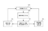
- FIG. 2 is a schematic diagram showing the concept of the basic principle of controlling the operation of the controlled device according to the present embodiment.
- the basic principle shown in FIG. 2 represents a control rule of an actuator (here, an actuator included in the learning support device 1) that can be used to realize human movement, and a position is input by using the current position of the actuator as an input.
- the operation of the actuator is determined by performing an operation in at least one region of (or velocity) or force. That is, the basic principle of controlling the operation of the control target device in the present embodiment is the control target system CS, the force / speed allocation conversion block FT for each function, the ideal power source block FC, or the ideal speed (position) source block PC. It is expressed as a control rule including at least one of the above and the inverse conversion block IFT.
- the controlled target system CS is a robot operated by an actuator (here, learning support device 1), and controls the actuator based on acceleration or the like.
- the controlled target system CS realizes the function of one or a plurality of parts in the human body, but if the control rule for realizing the function is applied, the specific configuration is It does not necessarily have to be a form that imitates the human body.
- the controlled target system CS can be a robot that causes a link to perform a one-dimensional sliding motion by an actuator.
- the function-specific force / speed allocation conversion block FT is a block that defines the conversion of control energy into the speed (position) and force regions set according to the function of the controlled system CS.
- coordinate conversion is defined in which a reference value (reference value) of the function of the controlled target system CS and the current position of the actuator are input.
- this coordinate transformation converts an input vector having a reference value and a current velocity (position) as elements into an output vector consisting of a velocity (position) for calculating a control target value of the velocity (position), and also converts the reference value.
- the input vector whose element is the current force is converted into the output vector consisting of the force for calculating the control target value of the force.
- the coordinate transformation in the force / velocity allocation conversion block FT for each function is generalized as in the following equations (1) and (2).
- x '1 ⁇ x' n (n is an integer of 1 or more) is the velocity vector for deriving the state value of the velocity
- x 'a ⁇ x' m (m is 1 or more
- Integer is a vector whose elements are the reference value and the velocity based on the action of the actuator (the velocity of the mover of the actuator or the velocity of the object moved by the actuator)
- h 1a to h nm are elements of the transformation matrix representing the function. Is.
- f '' 1 ⁇ f '' n (n is an integer of 1 or more) is the force vector for deriving the status value of the force
- f '' a ⁇ f ' ' m ( m is an integer of 1 or more) is a vector whose elements are the reference value and the force based on the action of the actuator (the force of the mover of the actuator or the force of the object to be moved by the actuator).
- the system expressing the function of realizing the variable (variable in the real space) of the actuator alone in the function-specific force / speed allocation conversion block FT. It "converts" to the entire set of variables (variables in virtual space), and allocates control energy to the control energy of velocity (position) and the control energy of force. Therefore, it is possible to independently give the control energy of the velocity (position) and the control energy of the force as compared with the case where the control is performed with the variable (variable in the real space) of the actuator alone.
- the ideal force source block FC is a block that performs calculations in the force region according to the coordinate transformation defined by the functional force / velocity allocation conversion block FT.
- a target value related to the force when performing a calculation based on the coordinate transformation defined by the functional force / velocity allocation conversion block FT is set.
- This target value is set as a fixed value or a variable value depending on the function to be realized. For example, when realizing a function similar to the function indicated by the reference value, zero is set as the target value, and when scaling is performed, a value obtained by enlarging / reducing the information indicating the function to be reproduced is set. can.
- the ideal velocity (position) source block PC is a block that performs calculations in the velocity (position) region according to the coordinate transformation defined by the functional force / velocity allocation conversion block FT.
- a target value regarding the speed (position) when performing a calculation based on the coordinate conversion defined by the function-specific force / speed allocation conversion block FT is set.
- This target value is set as a fixed value or a variable value depending on the function to be realized. For example, when realizing a function similar to the function indicated by the reference value, zero is set as the target value, and when scaling is performed, a value obtained by enlarging / reducing the information indicating the function to be reproduced is set. can.
- the inverse conversion block IFT is a block that converts the values in the region of velocity (position) and force into the values in the region of input to the controlled system CS (for example, voltage value or current value). Based on such a basic principle, when the position information in the actuator of the controlled target system CS is input to the function-specific force / speed allocation conversion block FT, the speed (position) and force information obtained based on the position information is obtained. In the function-specific force / velocity allocation conversion block FT, control rules for each position and force region according to the function are applied. Then, in the ideal power source block FC, the force is calculated according to the function, and in the ideal speed (position) source block PC, the speed (position) is calculated according to the function, and the force and the speed (position) are calculated. Control energy is distributed to each.
- the calculation results in the ideal power source block FC and the ideal speed (position) source block PC are information indicating the control target of the controlled target system CS, and these calculation results are used as the input values of the actuators in the inverse conversion block IFT for control. It is input to the target system CS.
- the actuator of the controlled target system CS executes an operation according to the function defined by the function-specific force / speed allocation conversion block FT, and the desired robot operation is realized. That is, in the present embodiment, the robot (here, each learning support device 1) can more appropriately realize the human movement at the time of a predetermined action.
- the force in the actuator is represented by the product of mass and acceleration
- the velocity (position) in the actuator is represented by the integral of acceleration. Therefore, by controlling the velocity (position) and the force through the region of acceleration, the current position of the actuator can be acquired and the desired function can be realized.
- FIG. 3 is a schematic diagram showing the concept of control when the force / tactile transmission function is defined in the function-specific force / speed allocation conversion block FT.
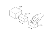
- FIG. 4 shows the concept of a master / slave system including a master device (for example, one of the learning support devices 1) and a slave device (for example, another learning support device 1) to which the force / tactile transmission function is applied. It is a schematic diagram which shows. As shown in FIG. 4, as a function defined by the force / speed allocation conversion block FT for each function, the operation of the master device is transmitted to the slave device, and the reaction from the object (for example, the work object 4) to the slave device is performed. It is possible to realize a function (bilateral control function) of feeding back the force input to the master device. In this case, the coordinate transformation in the functional force / velocity allocation conversion block FT is expressed by the following equations (3) and (4).
- x 'p is the rate
- x for deriving the state value of the velocity (position)' is f is the velocity on the status value of the force.
- x' x s is the current speed of the slave device (differential value of the current position).
- f p is a force related to the state value of the velocity (position)
- f f is a force for deriving the state value of the force.
- f m is the force of the reference value (input from the master device)
- f s is the current force of the slave device.
- a plurality of actuators included in the learning support device 1 following the movement of a human moving the hand to operate the learning support device 1.
- the position of each actuator when each of them moves is detected by a plurality of position sensors (illustrated in FIG. 7 described later) in chronological order, and these positions are stored in a storage device. ..
- each value for deriving the state value obtained as the coordinate conversion result in the force / velocity allocation conversion block FT for each function for example, calculated in time series.
- Each value on the left side of the equation (4) may be stored in the storage device.
- FIG. 5 is a schematic diagram showing an example of information stored as an extraction result of the motion
- FIG. 5A shows a case where the time-series positions of a plurality of actuators (here, actuators A1 to A4) are stored.
- FIG. 5B shows a case where the coordinate conversion result of the time-series equation (4) is stored.
- the actuator A1 stores a time-series position such as position p1 at time t1, position p2 at time t2, position p3 at time t3, and so on.
- FIG. 5A for example, the actuator A1 stores a time-series position such as position p1 at time t1, position p2 at time t2, position p3 at time t3, and so on.
- the scaling function is a function that enlarges or reduces the scale of the output position, force, or time with respect to the reference control.
- the scaling function for example, the magnitude of the movement of the master device can be reduced and reproduced on the slave device, the strength (force) of the movement of the master device can be increased and reproduced on the slave device, or the movement of the master device can be reproduced. It can be reproduced by a slave device by reducing the speed of.
- the scaling function for at least one of the information of the position or the force stored in the storage device, for example, the magnitude of the stored movement can be reduced and reproduced by the slave device, or the strength of the stored movement can be reduced. It can be reproduced by a slave device by strengthening the memory (force).
- the position of the slave device is multiplied by ⁇ ( ⁇ is a positive number)
- the force of the slave device is multiplied by ⁇ ( ⁇ is a positive number)
- the master device is used. Be transmitted.
- Such a scaling function is effective, for example, when performing delicate work such as surgery or microassembly, or large-scale work such as civil engineering work or extravehicular activity.
- the slave device and the master device can be obtained by applying the coordinate transformations of the equations (7) and (8). Is controlled to a similar position.
- the scaling function is activated by applying the coordinate transformations of the equations (9) and (10) so that the slave device does not exceed the position of (1 / b + a). Be controlled.
- Such a scaling function is effective, for example, when protecting an organ or avoiding a breakage of an object in surgery.
- FIG. 6 is a schematic diagram showing the concept of controlling the force / tactile transmission function using scaling in the frequency domain.
- the outputs of the master device and the slave device are input to the functional force / speed allocation conversion block FT after passing through the high-pass filter (HPF) and the low-pass filter (LPF), respectively.
- HPF high-pass filter
- LPF low-pass filter
- the function-specific force / speed allocation conversion block FT coordinate transformation for the high frequency range is applied to the output of the master device and slave device that have passed through the high-pass filter, and the output of the master device and slave device that has passed through the low-pass filter is applied.
- the coordinate transformation for the low frequency range is applied. That is, the function-based force / speed allocation conversion block FT separates the inputs from the master device and the slave device into high-frequency and low-frequency signals, and applies coordinate conversion corresponding to each frequency range.
- the target is to thin out or interpolate the information indicating the learned and stored function (for example, the time series data representing the extraction result of the action shown in FIG. 5). By setting it as a value, time scaling can be realized. Specifically, it is stored by thinning out information indicating a function that has been learned and stored, and then using it as a target value for calculation in the ideal force source block FC or the ideal speed (position) source block PC. Functions (operations) can be reproduced at high speed. Similarly, by interpolating the information indicating the learned and stored function and using it as the target value, the stored function (operation) can be reproduced at a low speed.
- FIG. 7 is a schematic diagram showing the basic configuration of the learning support device 1.
- the learning support device 1 includes a control unit 10, a control unit 10, a driver 20, an actuator 30, and a position sensor 40.
- the learning support device 1 operates as a master device or a slave device as described above with reference to FIG. 1, and when operating as one of the master device and the slave device, the learning support device 1 operates as the other device.
- the detection result of the position sensor 40 installed in the actuator 30 of the device 1 is used as an input to perform an operation according to the function.
- the functions implemented in the learning support device 1 can be variously changed by switching the coordinate conversion defined by the function-specific force / speed allocation conversion block FT realized by the control unit 10. ..
- the control unit 10 controls the entire learning support device 1, and is composed of a processor such as a CPU (Central Processing Unit) and an information processing device including a storage device such as a memory or a hard disk.
- the control unit 10 has functions of the function-specific force / speed allocation conversion block FT, the ideal power source block FC, the ideal speed (position) source block PC, and the inverse conversion block IFT in FIGS. 2 and 3. .. Then, the control unit 10 controls to operate as one of the master device and the slave device by these functions. Therefore, the control unit 10 acquires a reference value (hereinafter, referred to as “reference value”) for each function provided in the learning support device 1.
- reference value hereinafter, referred to as “reference value”
- This reference value is, for example, a time-series detection value output from the position sensor 40 installed in the actuator 30 of the learning support device 1 that operates as one of the master device and the slave device.
- the control unit 10 is configured by a communication interface (communication I / F). Can be done. Further, in order to realize the above-mentioned (motion extraction function), a case where the time-series detection value of the learning support device 1 operating as the other device is stored and sequentially read as a reference value to be acquired by the control unit 10.
- the control unit 10 can be configured by a storage device such as a memory or a hard disk.
- the time-series detection value detected by the position sensor 40 of the learning support device 1 that operates as the other device is input to the control unit 10 as a reference value.
- the time-series detection values represent the operation of the learning support device 1 that operates as the other device, and the control unit 10 has the speed (position) and force derived from the input detection value (position). Apply the coordinate transformation set according to the function to the information.
- control unit 10 performs an operation in the area of the velocity (position) with respect to the velocity (position) for deriving the state value of the velocity (position) obtained by the coordinate conversion. Similarly, the control unit 10 performs an operation in the force region with respect to the force for deriving the state value of the force obtained by the coordinate transformation. Further, the control unit 10 performs dimensional unification processing such as acceleration on the calculation result in the calculated velocity (position) region and the calculation result in the force region, and is set according to the function. Apply the inverse transformation of the coordinate transformation. As a result, the control unit 10 converts the calculation result in the calculated velocity (position) region and the calculation result in the force region into the value in the region of the input to the actuator 30.
- control unit 10 a functional block for supporting the learner to acquire the movement functions. This functional block will be described later with reference to FIG.
- the driver 20 converts the value in the region of the input to the actuator 30 that has been inversely converted by the control unit 10 into a specific control command value (voltage value, current value, etc.) for the actuator 30, and converts the control command value into the actuator 30. Output to.
- the actuator 30 is driven according to a control command value input from the driver 20 to control the position of the controlled device.
- the position sensor 40 detects the position of the controlled target device controlled by the actuator 30 and outputs the detected value to the control unit 10.
- the learning support device 1 converts the velocity (position) and force obtained from the position of the controlled object device detected by the position sensor 40 into the velocity (position) region and force by coordinate conversion according to the function. Convert to the state value of the area of. As a result, control energy is distributed to each of the velocity (position) and the force according to the function. Then, each state value is inversely transformed into a control command value, and the actuator 30 is driven by the driver 20 according to the control command value.
- the learning support device 1 can calculate the state values of the speed (position) and the force required to realize the desired function by detecting the position of the controlled device, and these state values. By driving the actuator 30 based on the above, the position and force of the controlled target device can be controlled to the desired state.
- the learning support device 1 can realize different functions by switching the coordinate conversion according to the function in the control unit 10.
- the storage device provided in the learning support device 1 stores coordinate transformations corresponding to various functions corresponding to a plurality of functions, and performs coordinate transformations according to one of the functions according to the purpose. By selecting it, it becomes possible to realize various functions in the learning support device 1.
- the learning support device 1 when realizing the above-mentioned function as (force / tactile transmission function), the learning support device 1 sets a reference value input to the control unit 10 in real time from the learning support device 1 operating as the other device. It can be the acquired value of the input position and force.
- the learning support device 1 can be controlled in real time in conjunction with the operation of the learning support device 1 that operates as the other device. That is, in this case, since the coordinate transformation represented by the equation (2) is defined in the control unit 10, the position of the actuator 30 of the learning support device 1 operating as the master device and the learning support device operating as the slave device. It is controlled so that the difference from the position of the actuator 30 of 1 becomes zero.
- the force / tactile sensation in the operation applied by the operator to the actuator 30 of the learning support device 1 operating as the master device is transmitted to the slave device, and the slave device is used.
- the reaction force from the object (for example, the work object 4) acting on the actuator 30 of the operating learning support device 1 is fed back to the master device.
- the operation performed on the learning support device 1 operating as the master device is accurately reproduced by the learning support device 1 operating as the slave device, and is input to the learning support device 1 operating as the slave device.
- the reaction force from the object can be accurately transmitted to the learning support device 1 that operates as the master device.
- the learning support device 1 is the other device in which the reference value input to the control unit 10 is acquired and stored in advance. It can be the acquired value of the time-series position and force of the learning support device 1 that operates as.
- the function of the learning support device 1 can be realized based on the operation of the learning support device 1 that operates as the other device prepared in advance. That is, in the absence of the learning support device 1 that operates as the other device, the learning support device 1 can reproduce the desired function.
- the learning support device 1 when the above-mentioned function is realized as (scaling function), the learning support device 1 reduces the magnitude of the movement of the learning support device 1 operating as, for example, the master device by the scaling function, and is a slave. It can be reproduced by the learning support device 1 that operates as a device, it can be reproduced by the learning support device 1 that operates as a slave device by strengthening the movement strength (force) of the learning support device 1 that operates as a master device, or it can be reproduced by the master. It is possible to reduce the speed of movement of the learning support device 1 operating as a device and reproduce it with the learning support device 1 operating as a slave device.
- the learning support device 1 is stored in the storage device by the motion extraction function.
- the scaling function for at least one of the position or force information, for example, the magnitude of the stored movement can be reduced and reproduced by the learning support device 1 that operates as a slave device, or the strength of the stored movement can be reproduced. It can be reproduced by the learning support device 1 that operates as a slave device by strengthening (force).
- the learning support device 1 that operates as a master device or a slave device further performs "learning support processing".
- the acquisition support process is a series of processes that support a learner who wants to acquire an action in a predetermined action.
- FIG. 8 is a block diagram showing hardware and functional blocks for realizing this learning support process.
- the control unit 10 includes a processor 11, a storage unit 12, a ROM 13, a RAM 14, a communication unit 15, an input unit 16, and an output unit 17. Further, as shown in FIG. 7, the driver 20 and the position sensor 40 are connected to the control unit 10. Each of these parts is connected by a signal line and sends and receives signals to and from each other.
- the processor 11 executes various processes according to the program recorded in the ROM 13 or the program loaded from the storage unit 12 into the RAM 14. Data and the like necessary for the processor 11 to execute various processes are also appropriately stored in the RAM 14.
- the storage unit 12 is composed of a semiconductor memory such as a DRAM (Dynamic Random Access Memory) and stores various data.
- the communication unit 15 controls communication for the processor 11 to communicate with another device (for example, another learning support device 1 or a terminal 2).
- the input unit 16 is composed of various buttons and a touch panel, or an external input device such as a mouse and a keyboard, and inputs various information according to a user's instruction operation.
- the output unit 17 is composed of a display, a speaker, or the like, and outputs images and sounds.
- the processor 11 has an operation control unit 111, a parameter acquisition unit 112, a display control unit 113, and a teacher data processing unit 114. And the force-tactile auxiliary unit 115 and the audiovisual auxiliary unit 116 function. Further, in the case of realizing the acquisition support processing in such a hardware configuration, as shown in FIG. 8, in one area of the storage unit 12, the teacher data storage unit 121, the execution data storage unit 122, and the auxiliary data Storage unit 123 and are set. Data necessary for realizing processing is appropriately transmitted and received between these functional blocks at appropriate timings, even if not specifically mentioned below.
- the motion control unit 111 controls the motion of the learning support device 1 that operates as the master device or the slave device by applying the force / tactile transmission function. That is, the motion control unit 111 functions as a function-specific force / speed allocation conversion block FT, an ideal power source block FC, an ideal speed (position) source block PC, and an inverse conversion block IFT in FIGS. 2 and 3. Realize. Further, in this case, the motion control unit 111 defines the force / tactile transmission function in the function-specific force / speed allocation conversion block FT as described above with reference to FIG. 3, and applies the force / tactile transmission function. Control the operation.
- the motion control unit 111 acquires teacher data (corresponding to the first control parameter) and execution data (to the second control parameter) acquired by the parameter acquisition unit 112, which will be described later, as one mode of presentation in the acquisition support process. Based on (equivalent), the movement is controlled by applying the force / tactile transmission function.
- the presentation in the learning support process is when the movement of the learning support device 1b (and the learning support device 1c) is controlled based on the movement by the user Ub who is an expert.
- the acquired teacher data and the execution data acquired when the operation of the acquisition support device 1a (and the acquisition support device 1c) is controlled based on the operation by the learner user Ua are transmitted to the learner user Ua. It is to be presented in a comparable manner.
- the motion control unit 111 controls the motion of the learning support device 1b operated by the expert user Ub with respect to the execution data of the learning support device 1a operated by the learner user Ua. Make corrections based on the teacher data used in. That is, the motion control unit 111 applies force-tactile sensation (that is, force-tactile sensation corresponding to the force applied by the expert user Ub to the actuator 30 of the learning support device 1b by operation) by the force / tactile transmission function. Communicates to the learning support device 1a operated by. As a result, the learner can grasp the presence or absence of the difference and the degree of the difference in the movement accompanied by the force and tactile sensation between the learner and the expert. Therefore, according to the presentation by the motion control unit 111, it is possible to more efficiently support the learner to acquire the motion.
- force-tactile sensation that is, force-tactile sensation corresponding to the force applied by the expert user Ub to the actuator 30 of the learning support device 1b by operation
- the parameter acquisition unit 112 acquires the control parameters used in the operation control to which the force / tactile transmission function applied by the operation control unit 111 (hereinafter, referred to as “control parameters related to force / tactile sensation”).
- the control parameter related to the force / tactile sensation may be any control parameter used by the motion control unit 111 for controlling the motion to which the force / tactile transmission function is applied.
- the coordinate conversion result of the equation (4) can be used as a control parameter related to force and tactile sensation.
- the parameter acquisition unit 112 acquires the time-series position of each actuator as a control parameter related to force and tactile sensation.
- the parameter acquisition unit 112 relates to the force-tactile sensation acquired when the expert user Ub operates the learning support device 1b as the master device to control the operation of the learning support device 1c which is the slave device.
- the control parameters are stored in the teacher data storage unit 121 as teacher data. Further, the parameter acquisition unit 112 acquires control parameters related to force and tactile sensation when the learner user Ua operates the learning support device 1a as a master device to control the operation of the learning support device 1c which is a slave device.
- the parameter acquisition unit 112 of the acquisition support device 1a acquires the teacher data and the execution data. Specifically, the parameter acquisition unit 112 of the acquisition support device 1a acquires teacher data from the motion control unit 111 included in the acquisition support device 1b.
- the parameter acquisition unit 112 of the acquisition support device 1a acquires execution data from the operation control unit 111 included in the own device (that is, the acquisition support device 1a).
- the parameter acquisition unit 112 of the acquisition support device 1a may acquire teacher data and execution data from the operation control unit 111 included in the acquisition support device 1c.
- the acquisition of the teacher data and the execution data may be performed in real time during the control of the operation of each learning support device 1, or may be performed temporarily during the control of the operation. Only storage (that is, buffering) may be performed, and acquisition may be performed collectively after control of operation is completed.
- the display control unit 113 displays based on the teacher data and the execution data as one aspect of the presentation in the acquisition support process. In addition, the display control unit 113 displays the user interface related to the acquisition support process.
- the display destination by the display control unit 113 is assumed to be the display provided in the terminal 2, but the display destination is not limited to this, and a display provided in another device may be the display destination.
- the learning support device 1 may include a display, and the display may be displayed on the display.
- FIGS. 9, 10, and 11 are schematic views showing an example of display based on teacher data and execution data by the display control unit 113, respectively.
- the display control unit 113 displays information indicating changes in the teacher data (indicated by the dotted line in the figure) along the time series and execution data (indicated by the solid line in the figure). At least a part of the presentation is realized by displaying the information indicating the change along the series in a superposed manner.
- the teacher data and the execution data are shown as changes along the time series of position, velocity, and force from above, respectively.
- the vertical axis is shown as a graph showing the position, velocity, and force from the top
- the horizontal axis is shown as a graph with time.
- these graphs may actually make smaller changes, the changes in the graphs are simplified and schematically shown in each figure.
- the positions of the actuator 30 along the time series are acquired as teacher data and execution data.
- the velocity in the actuator 30 can be expressed by the integral of the acceleration
- the force in the actuator 30 can be expressed by the product of the mass and the acceleration. Therefore, the display control unit 113 has a time series of position, speed, and force as shown in FIG. 9 based on the teacher data and execution data acquired by the parameter acquisition unit 112 and the calculation results such as integration with respect to these. It is possible to realize the display of changes along with.
- the learner who refers to such a display can grasp the presence or absence of the difference and the degree of the difference in the movement accompanied by the force and tactile sensation between himself and the expert in chronological order. For example, it is possible to grasp that the operation at which timing is not different, but the operation at which timing is significantly different. Therefore, not only the presentation by the motion control unit 111 (that is, the transmission of force and tactile sensation) but also the presentation by the display control unit 113 (that is, the display in chronological order) enables the learner to learn the motion more efficiently. Can help. In the following description, it is assumed that both the presentation by the operation control unit 111 and the presentation by the display control unit 113 are performed, but the present invention is not limited to this, and only one of the presentations may be performed.
- (Axis offset) It is also possible for the learner to further perform processing for making it easier for the learner to compare the teacher data and the execution data in the superimposed display of the graphs along the time series by the display control unit 113. For example, it is possible to display after adjusting the deviation (that is, offset) between the teacher data and the execution data on the vertical axis and the horizontal axis according to the user's operation or the like. For example, regarding changes in values indicating position, velocity, and force (that is, the vertical axis), there is not much difference between the teacher data and the execution data, or the timing of the change (that is, the horizontal axis) is different. There are cases like this.
- the execution data or the teacher data is moved to the horizontal axis and displayed.
- the execution data is moved to the horizontal axis and displayed.
- Comparative quantification Further, in the superimposed display of the graphs along the time series by the display control unit 113, not only the comparative display of superimposing the graphs but also the teacher data and the execution for an arbitrary time width at an arbitrary timing, for example.
- a comparative display may be performed in which the degree of discrepancy or the degree of concordance of the data is quantified.
- an arbitrary time width at an arbitrary timing is selected according to a user operation or the like. For example, as shown in the hatched area in FIG. 11, the selection of the time width to be quantified is accepted.
- the display control unit 113 calculates a comparison result quantifying the degree of discrepancy between the teacher data and the execution data in the selected time width for each of the position, the speed, and the force. Then, this comparison result is displayed, for example, as shown in FIG. 11 as an “error value”. This allows the learner to compare the results of quantifying the degree of discrepancy.
- a method of quantifying the degree of inconsistency between the teacher data and the execution data for example, a method of obtaining the degree of inconsistency between the teacher data and the execution data by the minimum self-squared error, a method of obtaining the degree of inconsistency between the teacher data and the execution data by the cosine similarity, etc. There is a method of obtaining based on the index of.
- the display control unit 113 may perform any of the above-mentioned (superimposed display), (axis offset), and (quantification of comparison). Depending on the operation or the like, these may be combined.
- the teacher data processing unit 114 processes the teacher data used in the above-mentioned presentation by the motion control unit 111 and the presentation by the display control unit 113 from the actual teacher data acquired by the parameter acquisition unit 112 prior to the presentation.
- the teacher data processing unit 114 processes teacher data when it is set to perform processing in advance or when there is a processing instruction operation from a user Ua or the like who is a learner.
- the processing of teacher data by the teacher data processing unit 114 will be described with reference to FIGS. 12 and 13. 12 and 13 are schematic views showing an example of processing of teacher data by the teacher data processing unit 114, respectively.
- the teacher data processing unit 114 performs scaling so as to enlarge or reduce the value of the position or force in the teacher data, for example, as the processing of the teacher data.
- This scaling is realized by the teacher data processing unit 114 performing processing to which the above-mentioned (force / tactile transmission function accompanied by scaling) is applied to the teacher data in response to an operation of the learner user Ua or the like. can.
- scaling is performed so as to expand the value indicating the position or force in the teacher data.
- the movement corresponding to the position and force of the teacher data becomes a rough movement that is coarser than the delicate movement by a skilled person. In other words, for the learner, the movement is less difficult to learn.
- the teacher data processing unit 114 performs such scaling, the motion control unit 111 and the display control unit 113 make a presentation, so that the learner can easily learn this operation.
- the degree of difficulty of learning is lowered by setting a large expansion rate of the position and force values in scaling.
- the learner learns the degree of difficulty of learning is gradually increased by gradually bringing the expansion rate of the position and the force value closer to the original teacher data. This makes it possible to more efficiently support the learner's acquisition of movements.
- the teacher data processing unit 114 scales the teacher data so that, for example, the change in the value indicating the position or force in the teacher data becomes longer or shorter in time. This scaling is performed by the teacher data processing unit 114 performing a process to which the above-mentioned (reproduction of the function using time scaling) is applied to the teacher data in response to an operation of the learner user Ua or the like. realizable.
- scaling is performed so that the change in the value indicating the position or force in the teacher data becomes longer in time.
- the movement corresponding to the position and force of the teacher data becomes a slow movement, which is slower than the quick movement by the expert. In other words, for the learner, the movement is less difficult to learn.
- the teacher data processing unit 114 performs such scaling, the motion control unit 111 and the display control unit 113 make a presentation, so that the learner can easily learn this operation. In this way, in the initial stage of learning, the degree to which the change of the value indicating the position or force in scaling becomes long in time is set to be large, and the difficulty of learning is lowered.
- the learner's learning progresses, the degree to which the change in the value indicating the position or force value gradually becomes longer in time approaches the original teacher data, and the difficulty of learning is increased. This makes it possible to more efficiently support the learner's acquisition of movements.
- the teacher data processing unit 114 extracts, for example, a part characterized by a change in the value indicating the position or force in the teacher data, repeats the extracted part, or changes the order of the extracted parts. You can make edits such as swapping. This editing can be realized by the teacher data processing unit 114 editing the teacher data according to the operation of the user Ua or the like who is a learner.
- the teacher data processing unit 114 may perform any of the above-mentioned (position / force scaling), (time scaling), and (editing of teacher data), but for example, the user Ua who is a learner. These may be combined and performed according to the operation such as.
- the force-tactile assist unit 115 acquires force-tactile assist data which is a control parameter for controlling the learning support device 1a so as to assist the operation of the user Ua who is a learner. Then, the force-tactile assisting unit 115 corrects the execution data of the learning support device 1a operated by the learner user Ua with the force-tactile assisting data. That is, the motion control unit 111 operates the force-tactile sense (that is, the force-tactile sense for controlling the learning support device 1a so as to assist the operation of the user Ua who is the learner) by the force / tactile sense transmission function. Communicate to the learning support device 1a. As a result, the movement by the learner can be assisted hapticly, and the learner can more efficiently assist the learner in learning the movement.
- force-tactile assist data which is a control parameter for controlling the learning support device 1a so as to assist the operation of the user Ua who is a learner.
- the force-tactile assist unit 115 should perform force-tactile assistance when it is set in advance to perform force-tactile assistance, or based on the operation of the learning support device 1a which operates as a master device in this process. When the condition is satisfied, it is determined that force-tactile assistance is provided. Further, the force-tactile auxiliary data acquired by the force-tactile auxiliary unit 115 is created by a user or the like and stored in the auxiliary data storage unit 123. That is, the auxiliary data storage unit 123 functions as a storage unit for storing force-tactile auxiliary data. Depending on the force-tactile auxiliary data, for example, it may be generated based on the teacher data or may be acquired by communication from another device. The assist using the force-tactile assist data by the force-tactile assist unit 115 may be performed together with the presentation by the motion control unit 111, but is not limited to this, and is separately from the presentation by the motion control unit 111. May be done in.
- the force-tactile assist unit 115 assists using the force-tactile assist data, for example, by a skilled user Ub based on real-time remote control.
- the learning support device 1b operated by the expert user Ub is the master device. Therefore, the learning support device 1a functions as a slave device (however, in relation to the learning support device 1c, it is a master device).
- the expert user Ub can remotely control the learning support device 1a in real time during learning. Therefore, the expert user Ub can transmit the force and tactile sensations such as delicate movements and force adjustments to the learner user Ua in real time. That is, real-time force-tactile assistance can support learning more efficiently. Further, in this case, by applying the above-mentioned (scaling function), it is possible to adjust the degree of transmitting the operation of the expert user Ub to the learner user Ua. As a result, for example, in the early stage of learning, it is possible to make adjustments such as strengthening the degree of communication and communicating firmly, and gradually weakening the degree of communication as the learning progresses. ..
- the force-tactile assisting unit 115 assists using the force-tactile assisting data, for example, by using suction force.
- FIG. 1 will be referred to as appropriate.
- the force-tactile auxiliary unit 115 sets a virtual target point 5 as shown in FIG. 1, and generates a force that attracts the virtual target point 5 toward the target point 5 in the vicinity of the virtual target point 5. And assist in moving to the target point.
- the virtual target point 5 is, for example, a point (or a passing point to reach that point) that is the target of work such as processing of the work object 4 by the end effector 3 of the learning support device 1c.
- the position of the virtual target point 5 may be preset as force-tactile auxiliary data and stored in the auxiliary data storage unit 123, or may be generated based on the teacher data.
- the suction force for example, the positional relationship between the current position of the end effector 3 of the learning support device 1c derived from the execution data and the position of the virtual target point 5 is a predetermined relationship (for example, in the vicinity). It is generated when it becomes.
- This suction force can be realized by correcting the execution data so that the force-tactile sensation sucked with respect to the position of the virtual target point 5 is transmitted to the acquisition support device 1a.
- the user Ua who is a learner, can be appropriately guided to a point to be worked on, and learning can be supported more efficiently.
- the force-tactile assist unit 115 provides, for example, assistance using direction presentation as an assist using the force-tactile assist data.
- the force-tactile auxiliary unit 115 presents the direction by generating a feeling that the ball bounces finely so that the direction to the target point can be known, for example. Therefore, the force-tactile auxiliary unit 115 sets a virtual target point 5 as shown in FIG. 1 in the same manner as described above (assistance by suction force). For example, only one virtual target point 5 may be set corresponding to a point to be the target of work such as machining, but the movement path to the point to be the target of work such as machining may be set. A plurality of corresponding settings may be set.
- each of the plurality of virtual target points 5 for reproducing such a movement path may be preset as force-tactile auxiliary data and stored in the auxiliary data storage unit 123, or may be stored in the auxiliary data storage unit 123, or the teacher data. It may be generated based on. Regarding the bounce feeling, the current position of the end effector 3 of the learning support device 1c derived from the execution data and the position of the virtual target point 5 (for example, a plurality of virtual target points 5 corresponding to the movement path).
- This bounce feeling is such that the direction toward the virtual target point 5 (for example, the direction of the virtual target point 5 closest to the current position of the end effector 3) can be presented to the learner user Ua.
- a bounce feeling is generated, and the end effector 3 is moving toward the virtual target point 5. Don't feel bouncing.
- This bounce feeling can be realized by correcting the execution data so that the force tactile sensation corresponding to the bounce feeling is transmitted to the acquisition support device 1a.
- the bounce cycle and the degree of bounce strength in the bounce feel may be different in stages. For example, a stronger bounce feeling may be generated in a shorter cycle as the direction moves away from the virtual target point 5.
- a bounce feeling is generated, and the direction away from the virtual target point 5 is generated. You may not feel the bounce when heading towards.
- the user Ua who is a learner, can be appropriately guided in the direction of the point to be worked on or the direction of the movement path to the point to be worked on, and the learning can be performed more efficiently. Can be assisted.
- the force-tactile assist unit 115 provides assistance using, for example, a repulsive force as an assist using the force-tactile assist data.
- the force-tactile auxiliary unit 115 generates a repulsive force such as when it comes into contact with a spring, a damper, or the like in the vicinity of the entry-prohibited area, and the end effector 3 of the learning support device 1c enters the entry-prohibited area. Do not enter. Therefore, the force-tactile auxiliary unit 115 sets a virtual entry prohibition area 7 as shown in FIG.
- the virtual entry prohibition area 7 is an area for prohibiting work such as processing of the work object 4 by the end effector 3 of the learning support device 1c (that is, entry of the end effector 3).
- the area to be the virtual entry prohibited area 7 may be preset as force-tactile auxiliary data and stored in the auxiliary data storage unit 123, or may be generated based on the teacher data. For example, a region corresponding to the other layer is set as a virtual entry prohibition region 7 so that cutting is performed on any one of two layers of plates made of different materials.
- the positional relationship between the current position of the end effector 3 of the learning support device 1c derived from the execution data and the area corresponding to the virtual entry prohibited area 7 is a predetermined relationship (for example,). It is generated when it becomes (within a predetermined range).
- This repulsive force can be realized by correcting the execution data so that the force-tactile sensation corresponding to the elastic force or the viscous force is transmitted to the acquisition support device 1a.
- the operation of the user Ua who is a learner it is possible to prevent the user from entering the prohibited area, and it is possible to support the learning more efficiently.
- the force-tactile assist unit 115 assists using the force-tactile assist data, for example, by using a feel such as a rough feeling.
- the force-tactile auxiliary unit 115 generates a rough feeling or the like in the vicinity of the entry prohibited area, and the user who is a learner indicates that the end effector 3 of the learning support device 1c is approaching the entry prohibited area. Notify Ua. Therefore, the force-tactile auxiliary unit 115 sets a virtual entry prohibition area 7 as shown in FIG. 1 in the same manner as described above (assistance by repulsive force).
- the positional relationship between the current position of the end effector 3 of the learning support device 1c derived from the execution data and the area corresponding to the virtual entry prohibited area 7 is a predetermined relationship (for example,). It is generated when it becomes (within a predetermined range).
- This rough feeling can be realized by correcting the execution data so that the force-tactile sensation corresponding to the feeling such as the rough feeling is transmitted to the acquisition support device 1a with respect to the area of the virtual entry prohibited area 7. can.
- the operation of the user Ua who is a learner it is possible to notify that the user is approaching the restricted area, and it is possible to support learning more efficiently.
- the region where the repulsive force or rough feeling is generated has a positional relationship with the region corresponding to the entry prohibited area 7 as described above.
- the region may be, but is not limited to, a region having a predetermined relationship (for example, within a predetermined range). For example, as in the virtual wall 8 and the virtual wall 9 as shown in FIG.
- the work range in which the end effector 3 of the learning support device 1c should not be moved in the work such as processing the work object 4 (for example, a repulsive force or a rough feeling may be generated in an area such as a virtual wall indicating (a work range that interferes with another learning support device 1 or another user U) (not shown).
- the force-tactile assist unit 115 provides assistance using, for example, position scaling as an assist using the force-tactile assist data.
- the force-tactile auxiliary unit 115 adjusts the degree of position scaling according to the current position of the end effector 3 of the learning support device 1c, so that the master device may be moved too much. It is possible to prevent the slave device from moving too much beyond a predetermined position.
- the force-tactile auxiliary unit 115 is a virtual entry prohibition area 7 (or a virtual entry prohibition position) as shown in FIG. 1 in the same manner as described above (assistance by repulsive force). May be good.) Is set. For example, in addition to this, a region or position where work such as processing cannot proceed is set. Regarding the adjustment of the degree of position scaling, for example, the closer the current position of the end effector 3 of the learning support device 1c derived from the execution data is to the area corresponding to the virtual entry prohibited area 7, the position of the master device. The degree of scaling should be increased so that the position of the slave device does not move even if the device moves.
- the scaling function is applied as described above (force / tactile transmission function with position limitation by scaling), and the slave device is at the position (1 / b + a) (that is,).
- This can be realized by controlling the position corresponding to the virtual entry prohibited area 7 or the virtual entry prohibited area) so as not to exceed the position.
- the slave device moves too much from a predetermined position (that is, a position corresponding to the virtual entry prohibition area 7 or a virtual entry prohibition position). Can be prevented, and learning can be supported more efficiently.
- the force-tactile assist unit 115 includes the above-mentioned (assistance by real-time remote control), (assistance by suction force), (assistance by direction presentation), (assistance by repulsive force), (assistance by rough feeling, etc.). And (assistance by position scaling adjustment) may be performed, but for example, these may be performed in combination according to the operation of the user Ua who is a learner or the like. Further, for example, the force-tactile assist unit 115 may partially replace these methods of force-tactile assistance. For example, the assistance using the suction force may be performed for the purpose of not entering the virtual entry prohibited area 7, or the touch such as the suction force, the repulsive force, or the rough feeling may be used for the purpose of presenting the direction. Assistance may be provided.
- the audiovisual auxiliary unit 116 presents auxiliary information, which is information for assisting the operation of the learner user Ua, to the learner user Ua.
- This presentation is realized, for example, by displaying on a display provided in the terminal 2 or the like, outputting a sound (warning sound, voice, etc.) from a speaker provided in the terminal 2 or the like, blinking a warning light provided in the terminal 2 or the like, or the like.
- NS a sound
- the audiovisual assistance unit 116 satisfies the condition that the audiovisual assistance should be provided in advance, or the condition that the audiovisual assistance should be provided based on the operation of the learning support device 1a that operates as the master device in this process. If so, it is determined that audiovisual assistance is provided. Further, the audiovisual auxiliary data acquired by the audiovisual auxiliary unit 116 is created by a user or the like and stored in the auxiliary data storage unit 123. That is, the auxiliary data storage unit 123 not only stores the force-tactile auxiliary data, but also functions as a storage unit that further stores the audiovisual auxiliary data. Depending on the audiovisual auxiliary data, for example, it may be generated based on the teacher data, or it may be acquired by communication from another device. The assistance using the audiovisual assistance data by the audiovisual assistance unit 116 may be performed together with the presentation by the motion control unit 111, but is not limited to this, and is performed separately from the presentation by the motion control unit 111. You may be broken.
- FIG. 14 is a schematic diagram showing an example of an auxiliary display screen using audiovisual auxiliary data by the audiovisual auxiliary unit 116.
- the end effector 71 (corresponding to the end effector 3 in FIG. 1)
- the aerial portion 72 in which no object exists and the cutting target portion 73 (working object 4 in FIG. 1).
- the cutting target portion (corresponding to the cutting target portion), the cutting prohibited portion 74 (corresponding to the virtual entry prohibited region 7 of the work object 4 in FIG. 1), and the execution data display area 75 are represented by schematic computer graphics. ,Is displayed.
- the end effector 71 which is a cutting drill
- the end effector 71 is moved linearly from left to right in the drawing, and after passing through the aerial portion 72, the cutting target portion 73 is cut, but the cutting prohibited portion 74 is cut.
- these displays are displayed as moving images based on the change of the execution data according to the movement of the learning support device 1c.
- the user Ua who is a learner who has referred to such an auxiliary screen, can visually grasp how much the end effector 71 should be moved.
- the audiovisual auxiliary unit 116 can also provide assistance such as presenting an alert by sound warning, blinking of a warning light, or the like. For example, when the end effector 71 approaches the cutting prohibited portion 74 after entering the cutting target portion 73, an alert is presented by a sound warning, a blinking warning light, or the like.
- the audiovisual auxiliary unit 116 displays, for example, a change in a value indicating a force or the like along a time series in the execution data display area 75 as described above with reference to FIG. You can also. Further, the audiovisual auxiliary unit 116 assists by presenting an alert by sound warning, blinking of the warning light, etc., in addition to such a display, when an excessive force or the like unsuitable for work such as processing is generated. You can also do it. As a result, the movement by the learner can be visually assisted, and the learner can more efficiently support the acquisition of the movement.
- the configuration of the learning support device 1 has been explained in detail above. Next, the processing contents of each processing performed by the learning support system S including these learning support devices 1 will be described in more detail.
- FIG. 15 is a flowchart illustrating the flow of the teacher data acquisition process executed by the acquisition support system S.
- the teacher data acquisition process is a process executed prior to the acquisition support process, and is executed in accordance with a teacher data acquisition start instruction operation for the acquisition support system S from a skilled user Ub or the like.
- step S11 the learning support device 1b that operates as the master device in this process accepts the operation of the user Ub who is an expert.
- step S12 the motion control unit 111 included in the learning support device 1b operating as the master device in this process and the motion control unit 111 included in the learning support device 1c operating as the slave device in this process were accepted in step S11. It controls its own operation based on the operation of the expert user Ub. As described above, the force / tactile transmission function is applied to control this operation, and the operation of the master device is transmitted to the slave device and feedback from an object (for example, work object 4) to the slave device. The force input is fed back to the master device.
- an object for example, work object
- step S13 the motion control unit 111 included in the learning support device 1b determines whether or not the operation of the skilled user Ub has been completed. When the operation is completed, it is determined as Yes in step S13, and the process proceeds to step S14. On the other hand, if the operation is not completed, it is determined as No in step S13, and the process is repeated from step S11.
- step S14 the parameter acquisition unit 112 included in the acquisition support device 1b (or acquisition support device 1c) is used in the repetition of this time from step S11 to step S13, and the control parameters along the buffered time series are used. Is acquired as teacher data. Then, the parameter acquisition unit 112 included in the acquisition support device 1b (or the acquisition support device 1c) transmits the acquired teacher data to the parameter acquisition unit 112 included in the acquisition support device 1a.
- step S15 the motion control unit 111 included in the acquisition support device 1a stores the received teacher data in the teacher data storage unit 121 included in the acquisition support device 1a. This ends this process.
- FIG. 16 is a flowchart illustrating a flow of learning support processing executed by the learning support system S.
- the acquisition support process is a process that is executed after the teacher data is stored by the above-mentioned teacher data acquisition process, and is executed in accordance with the acquisition support start instruction operation for the acquisition support system S from the learner user Ua or the like. Will be done.
- step S21 the display control unit 113 acquires the teacher data to be presented this time from the teacher data storage unit 121.
- step S22 the teacher data processing unit 114 determines whether or not to process the teacher data acquired in step S21. For example, the teacher data processing unit 114 determines that the teacher data is processed when the processing is set in advance or when there is a processing instruction operation from the learner user Ua or the like. When processing the teacher data, it is determined as Yes in step S22, and the process proceeds to step S23. On the other hand, when the teacher data is not processed, it is determined as No in step S22, and the process proceeds to step S24. In step S23, the teacher data processing unit 114 processes the teacher data.
- step S24 the learning support device 1a that operates as the master device in this process accepts the operation of the user Ua who is a learner.
- step S25 the motion control unit 111 included in the learning support device 1a operating as the master device in this process and the motion control unit 111 included in the learning support device 1c operating as the slave device in this process were accepted in step S24.
- the operation of the own device is controlled based on the operation of the user Ub who is an expert and the teacher data acquired in step S21.
- the force / tactile transmission function is applied to control this operation, and the operation of the master device is transmitted to the slave device after applying the control parameters corresponding to the teacher data as one aspect of the presentation.
- the input of the reaction force from the object (for example, the work object 4) to the slave device is fed back to the master device.
- step S26 the force-tactile assist unit 115 determines whether or not to perform force-tactile assistance.
- the force-tactile assist unit 115 should perform force-tactile assistance when it is set in advance to perform force-tactile assistance, or based on the operation of the learning support device 1a which operates as a master device in this process.
- the condition is satisfied, it is determined that force-tactile assistance is provided.
- it is determined to be Yes in step S26, and the process proceeds to step S27.
- the force-tactile assistance is not performed, No is determined in step S26, and the process proceeds to step S28.
- step S27 the force-tactile assist unit 115 provides force-tactile assistance.
- step S28 the audiovisual assistance unit 116 determines whether or not to provide audiovisual assistance. For example, the audiovisual assistance unit 116 satisfies the condition that the audiovisual assistance should be provided in advance, or the condition that the audiovisual assistance should be provided based on the operation of the learning support device 1a that operates as the master device in this process. If so, it is determined that audiovisual assistance is provided. When the audiovisual assistance is performed, it is determined as Yes in step S28, and the process proceeds to step S29. On the other hand, when the audiovisual assistance is not performed, it is determined as No in step S28, and the process proceeds to step S30. In step S28, the audiovisual assistance unit 116 provides audiovisual assistance.
- step S30 the motion control unit 111 included in the learning support device 1b determines whether or not the operation of the learner user Ua has been completed. When the operation is completed, it is determined as Yes in step S30, and the process proceeds to step S31. On the other hand, if the operation is not completed, it is determined as No in step S30, and the process is repeated from step S24.
- step S31 the parameter acquisition unit 112 included in the learning support device 1b acquires control parameters along the buffered time series as execution data, which are used in the repetition from step S11 to step S13 this time. Then, the motion control unit 111 included in the acquisition support device 1a stores the acquired execution data in the teacher data storage unit 121 included in the acquisition support device 1a.
- step S32 the display control unit 113 determines whether or not the teacher data acquired in step S21 and the execution data acquired in step S31 are displayed in a comparable manner as one aspect of the presentation.
- the teacher data processing unit 114 determines that the display is comparable when the display is set to be performed in advance or when there is a display instruction operation from the learner user Ua or the like.
- the display is comparable, it is determined to be Yes in step S32, and the process proceeds to step S33.
- No is determined in step S32, and this process ends.
- the display control unit 113 displays at an arbitrary timing. Can be realized.
- step S33 the display control unit 113 displays the teacher data acquired in step S21 and the execution data acquired in step S31 in a comparable manner on a display such as the terminal 2 as one aspect of the presentation. This ends this process.
- the teacher data and the execution data which are control parameters related to force and tactile sensation, can be compared with the learner user Ua by the motion control unit 111 and the display control unit 113. Can be presented.
- the learner user Ua can grasp the presence or absence of the difference and the degree of the difference in the movement accompanied by the force and tactile sensation between the user Ua who is the learner and the user Ub who is the expert.
- acquisition support can be assisted by force-tactile assistance or audiovisual assistance as needed. Therefore, according to the learning support system S, it is possible to more efficiently support the learner's learning of movements.
- control unit 10 of each learning support device 1 has the same functional block. Not limited to this, even if some functional blocks are omitted for the control unit 10 of the learning support device 1 (for example, the learning support device 1b and the learning support device 1c in the above-described embodiment) that the learner does not use. good. For example, for the control unit 10 of the learning support device 1 that is not used by the learner, functional blocks other than the motion control unit 111 and the parameter acquisition unit 112 may be omitted.
- the presentation by the motion control unit 111, the presentation by the display control unit 113, the force-tactile assistance, and the audiovisual assistance are all executed as learning support for the learner. .. Not limited to this, only a part of these may be executed. Further, in this case, the functional block for realizing the learning support that is not executed may be omitted.
- the control unit 10 of each learning support device 1 includes an operation control unit 111, and each of these operation control units 111 controls the operation to provide a force / tactile transmission function or the like.
- devices for example, terminal 2 for performing operation control include the functional force / speed allocation conversion block FT, the ideal force source block FC, and the ideal speed (position) source in FIGS. 2 and 3.
- the functions of the block PC and the inverse conversion block IFT may be realized.
- the device for performing this motion control receives a reference value or the like from each learning support device 1, and based on the control of the device for performing this motion control, the force / tactile transmission function is transmitted to each learning support device 1. Etc. may be realized.
- the display control unit 113 displays the teacher data and the execution data in a comparable manner after the operation by the learner is completed.
- the teacher data and the execution data up to that point may be displayed in a comparable manner during the operation by the learner.
- the learner can grasp in real time during his / her own movement whether or not there is a difference in the movement accompanied by force and tactile sensation and the degree of the difference.
- the learning support device 1 (for example, in the above-described embodiment, the learning support device 1c) that operates as a slave device actually executes work such as machining. Then, it is assumed that the operation of the master device is transmitted to the slave device and the input of the reaction force from the object (for example, the work object 4) to the slave device is fed back to the master device.
- a virtual slave device in the virtual space may execute work such as processing on a virtual object. Then, the operation of the master device may be transmitted to the virtual slave device, and the input of the reaction force from the virtual object to the virtual slave device may be fed back to the master device.
- the contact of a virtual object is regarded as an action in the virtual slave device, and the energy allocation conversion of the position and the force is performed for the variable in the virtual space and the variable in the real space.
- force / tactile sensation is transmitted to and from the virtual object, and the force / tactile sensation received by the virtual slave device is transmitted.
- the teacher data acquisition process and the acquisition support process can be realized without actually performing work such as processing on the work object 4 or the like.
- the virtual object in the virtual space can be configured as a virtually generated object or an object in the real space reproduced in the virtual space based on the characteristics of the substance in the real space. ..
- the learning support system S includes an operation control unit 111, a parameter acquisition unit 112, an operation control unit 111, and a display control unit 113.
- the motion control unit 111 causes the control target device to perform an operation corresponding to the force-tactile sensation in the user's operation.
- the parameter acquisition unit 112 acquires the control parameters used in the control by the operation control unit 111.
- the operation control unit 111 and the display control unit 113 include the first control parameter acquired by the parameter acquisition unit 112 when the operation control unit 111 controls the operation of the control target device based on the operation by the first user, and the first control parameter.
- the second control parameter acquired by the parameter acquisition unit 112 when the operation control unit 111 controls the operation of the controlled device based on the operation by the second user is presented to the second user in a comparable manner. ..
- the control parameters used for causing the controlled target device to perform the operation corresponding to the force and tactile sensation in the operation of the user are set to the first user (for example, an expert) and the second user.
- the control parameters of each user are presented to the second user in a comparable manner.
- the second user can grasp the presence or absence of the difference and the degree of the difference in the movement accompanied by the force and tactile sensation between the second user and the first user. Therefore, according to the learning support system S, it is possible to more efficiently support the learner's learning of movements.
- the motion control unit 111 includes a position sensor 40, a force / speed allocation conversion block FT ideal force source block FC, and an ideal speed (position) source block PC in order to control the device to be controlled based on the operation by the user. It includes an inverse conversion block IFT and.
- the position sensor 40 detects information about the position that accompanies the operation of the control target device.
- the force / velocity allocation conversion block FT performs conversion for allocating control energy to energy of a predetermined physical quantity based on information on a predetermined physical quantity corresponding to information on a position and information as a reference for control.
- the ideal force source block FC and the ideal velocity (position) source block PC calculate a control amount of a predetermined physical quantity based on the energy of a predetermined physical quantity allocated by the force / velocity allocation conversion block FT.
- the inverse transformation block IFT reversely transforms the controlled amount to the controlled target device in order to return the output based on the controlled amount calculated by the ideal force source block FC and the ideal speed (position) source block PC to the controlled target device. Determine the input.
- the operation of the controlled target device can be controlled based on the control parameters related to the force-tactile sensation.
- the display control unit 113 displays the information indicating the change of the first control parameter along the time series and the information indicating the change of the second control parameter along the time series in a superposed manner. , Realize at least part of the presentation. As a result, the second user can easily visually grasp the presence or absence of the difference in time series and the degree of the difference between the second user and the first user regarding the movement accompanied by the force and tactile sensation. be able to.
- the display control unit 113 realizes at least a part of the presentation by correcting the second control parameter based on the first control parameter at the time of the operation of the control target device accompanying the operation of the second user. This makes it possible for the second user to easily grasp the difference in time series regarding the movement of the second user and the first user with the tactile sensation.
- the acquisition support system S further includes a teacher data processing unit 114.
- the teacher data processing unit 114 processes the first control parameter.
- the motion control unit 111 and the display control unit 113 use the first control parameter after processing by the teacher data processing unit 114.
- the presence or absence of a time-series difference and the degree of difference between the second user and the first user regarding the movement accompanied by the force-tactile sensation can be easily grasped by the second user through the force-tactile sensation. Can be made to.
- the other controlled target device operates in real time as a master device used by another user different from the second user, and the controlled target device is operated by the second user. Operates in real time as a slave device to be used.
- the master device and the slave device are communicated and connected to send and receive control parameters. As a result, it is possible to support the acquisition from another user in real time during the operation of the second user.
- the learning support system S further includes a force-tactile auxiliary unit 115.
- the force-tactile assist unit 115 corrects the second control parameter based on the third control parameter, which is a control parameter for controlling the controlled target device so as to assist the operation of the second user. As a result, the controlled device can be controlled so as to assist the operation of the second user.
- the learning support system S further includes an audiovisual assistance unit 116.
- the audiovisual auxiliary unit 116 presents auxiliary information, which is information for assisting the operation of the second user, based on the second control parameter.
- auxiliary information which is information for assisting the operation of the second user, can be output based on the state of the second control parameter.
- the processor that executes this arithmetic processing is composed of various processing units such as a single processor, a multiprocessor, and a multicore processor.
- various processing units such as a single processor, a multiprocessor, and a multicore processor.
- it includes a combination of these various processing units and a processing circuit such as an ASIC (Application Specific Integrated Circuit) or an FPGA (Field-Programmable Gate Array).
- ASIC Application Specific Integrated Circuit
- FPGA Field-Programmable Gate Array
- the programs constituting the software are installed in the computer via a network or a recording medium.
- the computer may be a computer in which dedicated hardware is incorporated, or a general-purpose computer capable of performing a predetermined function by installing a program (for example, a general-purpose personal computer or the like).
- a program for example, a general-purpose personal computer or the like.
- the step of writing a program may include only processes performed in chronological order in that order, but may include processes executed in parallel or individually.
- the steps for describing the program may be executed in any order within a range that does not deviate from the gist of the present invention.
- the recording medium on which such a program is recorded may be provided to the user by being distributed separately from the computer main body, or may be provided to the user in a state of being preliminarily incorporated in the computer main body.
- the storage medium distributed separately from the computer main body is composed of, for example, a magnetic disk (including a floppy disk), an optical disk, a magneto-optical disk, or the like.
- the optical disc is composed of, for example, a CD-ROM (Compact Disc-Read Only Memory), a DVD (Digital entirely Disc), a Blu-ray (registered trademark) Disc (Blu-ray disc), or the like.
- the magneto-optical disk is composed of, for example, MD (Mini Disc) or the like.
- the recording medium provided to the user in a state of being incorporated in the computer body in advance is composed of, for example, the storage unit 12 of FIG. 5 in which the program is recorded.
- 1a, 1b, 1c learning support device 2 terminal, 3 end effector, 4 work object, 5 virtual target point, 6 virtual direction feeling, 7 virtual no-entry area, 8, 9 virtual wall 10, 10 control unit, 11 processor, 111 motion control unit, 112 parameter acquisition unit, 113 display control unit, 114 teacher data processing unit, 115 force-tactile auxiliary unit, 116 audiovisual auxiliary unit, 12 storage unit, 121 teacher data storage Unit, 122 execution data storage unit, 123 auxiliary data storage unit, 13 ROM, 14 RAM, 15 communication unit, 16 input unit, 17 output unit, 20 driver, 30 actuator, 40 position sensor, CS controlled system, FT power -Speed allocation conversion block, FC ideal power source block, PC ideal speed (position) source block, IFT inverse conversion block, S acquisition support system, Ua, Ub user
Landscapes
- Engineering & Computer Science (AREA)
- Business, Economics & Management (AREA)
- Robotics (AREA)
- Mechanical Engineering (AREA)
- Physics & Mathematics (AREA)
- General Physics & Mathematics (AREA)
- Theoretical Computer Science (AREA)
- Educational Administration (AREA)
- Educational Technology (AREA)
- Entrepreneurship & Innovation (AREA)
- Tourism & Hospitality (AREA)
- Health & Medical Sciences (AREA)
- General Health & Medical Sciences (AREA)
- Human Resources & Organizations (AREA)
- Marketing (AREA)
- Primary Health Care (AREA)
- Strategic Management (AREA)
- General Business, Economics & Management (AREA)
- Economics (AREA)
- Automation & Control Theory (AREA)
- Manipulator (AREA)
Priority Applications (2)
| Application Number | Priority Date | Filing Date | Title |
|---|---|---|---|
| US17/802,937 US12562076B2 (en) | 2020-02-27 | 2021-02-26 | Learning assistance system, learning assistance method, and learning assistance storage medium |
| JP2022503375A JP7730107B2 (ja) | 2020-02-27 | 2021-02-26 | 習得支援システム、習得支援方法、及び習得支援プログラム |
Applications Claiming Priority (2)
| Application Number | Priority Date | Filing Date | Title |
|---|---|---|---|
| JP2020032474 | 2020-02-27 | ||
| JP2020-032474 | 2020-02-27 |
Publications (1)
| Publication Number | Publication Date |
|---|---|
| WO2021172572A1 true WO2021172572A1 (ja) | 2021-09-02 |
Family
ID=77491636
Family Applications (1)
| Application Number | Title | Priority Date | Filing Date |
|---|---|---|---|
| PCT/JP2021/007565 Ceased WO2021172572A1 (ja) | 2020-02-27 | 2021-02-26 | 習得支援システム、習得支援方法、及び習得支援プログラム |
Country Status (3)
| Country | Link |
|---|---|
| US (1) | US12562076B2 (https=) |
| JP (1) | JP7730107B2 (https=) |
| WO (1) | WO2021172572A1 (https=) |
Cited By (1)
| Publication number | Priority date | Publication date | Assignee | Title |
|---|---|---|---|---|
| US12498789B2 (en) | 2021-06-25 | 2025-12-16 | Keio University | Operational data management system, operational data management method, and storage medium |
Citations (8)
| Publication number | Priority date | Publication date | Assignee | Title |
|---|---|---|---|---|
| JP2001067113A (ja) * | 1999-08-30 | 2001-03-16 | Toshiba Corp | プラント操作評価システム |
| JP2002287613A (ja) * | 2001-03-28 | 2002-10-04 | Toshiba Corp | 操作訓練用装置 |
| JP2003340752A (ja) * | 2002-05-21 | 2003-12-02 | Toshiba Corp | 医療用マニピュレータ |
| JP2005515012A (ja) * | 2002-01-16 | 2005-05-26 | コンピュータ・モーション・インコーポレーテッド | ロボット工学およびテレコラボレーションを使用した最小侵襲性外科訓練 |
| JP2005287656A (ja) * | 2004-03-31 | 2005-10-20 | Nagoya Kogyo Univ | 力触覚を活用した鍼治療訓練システム |
| JP2014215563A (ja) * | 2013-04-26 | 2014-11-17 | 学校法人自治医科大学 | 手技シミュレータ |
| US20180250086A1 (en) * | 2017-03-02 | 2018-09-06 | KindHeart, Inc. | Telerobotic surgery system using minimally invasive surgical tool with variable force scaling and feedback and relayed communications between remote surgeon and surgery station |
| JP2019030960A (ja) * | 2013-09-19 | 2019-02-28 | 学校法人慶應義塾 | 位置・力制御装置、位置・力制御方法及びプログラム |
Family Cites Families (30)
| Publication number | Priority date | Publication date | Assignee | Title |
|---|---|---|---|---|
| JP3230615B2 (ja) | 1992-11-30 | 2001-11-19 | オリンパス光学工業株式会社 | 触診装置 |
| JP3248821B2 (ja) | 1994-11-18 | 2002-01-21 | 敏男 福田 | アクチュエータの作動方法及び装置 |
| JP3722994B2 (ja) | 1998-07-24 | 2005-11-30 | 大日本印刷株式会社 | 物体の接触感シミュレーション装置 |
| US8527094B2 (en) * | 1998-11-20 | 2013-09-03 | Intuitive Surgical Operations, Inc. | Multi-user medical robotic system for collaboration or training in minimally invasive surgical procedures |
| US10820949B2 (en) * | 1999-04-07 | 2020-11-03 | Intuitive Surgical Operations, Inc. | Medical robotic system with dynamically adjustable slave manipulator characteristics |
| JP4403474B2 (ja) | 1999-12-09 | 2010-01-27 | ソニー株式会社 | 触覚提示機構及びこれを用いた力触覚提示装置 |
| JP2002312003A (ja) | 2001-04-13 | 2002-10-25 | Yaskawa Electric Corp | サーボ制御方法 |
| JP4048999B2 (ja) | 2003-04-15 | 2008-02-20 | セイコーエプソン株式会社 | 画像処理装置及び画像処理方法 |
| US7672741B2 (en) | 2003-07-24 | 2010-03-02 | Keio University | Position/force control device |
| JP4613861B2 (ja) | 2006-03-30 | 2011-01-19 | アイシン・エィ・ダブリュ株式会社 | 電動駆動制御装置及び電動駆動制御方法 |
| WO2009035100A1 (ja) | 2007-09-14 | 2009-03-19 | National Institute Of Advanced Industrial Science And Technology | バーチャルリアリティ環境生成装置及びコントローラ装置 |
| US11325029B2 (en) | 2007-09-14 | 2022-05-10 | National Institute Of Advanced Industrial Science And Technology | Virtual reality environment generating apparatus and controller apparatus |
| JP5011067B2 (ja) | 2007-10-31 | 2012-08-29 | 株式会社東芝 | マニピュレータシステム |
| JP2009279699A (ja) | 2008-05-21 | 2009-12-03 | Nagaoka Univ Of Technology | 位置・力再現方法および位置・力再現装置 |
| JP5761730B2 (ja) | 2010-01-28 | 2015-08-12 | 長崎県公立大学法人 | 身体技能習得支援装置 |
| US9770828B2 (en) * | 2011-09-28 | 2017-09-26 | The Johns Hopkins University | Teleoperative-cooperative robotic system |
| WO2013108356A1 (ja) | 2012-01-16 | 2013-07-25 | 三菱電機株式会社 | モータ制御装置 |
| US9492920B2 (en) * | 2014-06-16 | 2016-11-15 | Panasonic Intellectual Property Management Co., Ltd. | Control apparatus and control method for master-slave robot, master-slave robot, control program for master-slave robot, and integrated electronic circuit for controlling master-slave robot |
| US11227509B2 (en) * | 2014-12-29 | 2022-01-18 | Help Me See Inc. | Surgical simulator systems and methods |
| US20180350086A1 (en) | 2017-05-31 | 2018-12-06 | Qualcomm Incorporated | System And Method Of Dynamically Filtering Depth Estimates To Generate A Volumetric Map Of A Three-Dimensional Environment Having An Adjustable Maximum Depth |
| JP7018759B2 (ja) | 2017-12-14 | 2022-02-14 | 学校法人慶應義塾 | 位置・力制御装置 |
| US11659023B2 (en) * | 2017-12-28 | 2023-05-23 | Cilag Gmbh International | Method of hub communication |
| JP6964293B2 (ja) | 2018-03-08 | 2021-11-10 | 地方独立行政法人神奈川県立産業技術総合研究所 | 力触覚伝達システム、力触覚伝達方法及びプログラム |
| JP6730363B2 (ja) * | 2018-04-13 | 2020-07-29 | ファナック株式会社 | 操作訓練システム |
| JP7347774B2 (ja) | 2018-07-06 | 2023-09-20 | 地方独立行政法人神奈川県立産業技術総合研究所 | 医療用把持装置 |
| JP7369383B2 (ja) | 2018-09-03 | 2023-10-26 | 慶應義塾 | 機能生成装置、機能生成方法及びプログラム |
| WO2020130091A1 (ja) * | 2018-12-21 | 2020-06-25 | 川崎重工業株式会社 | ロボットシステム及びロボットシステムの制御方法 |
| WO2020162619A1 (ja) | 2019-02-07 | 2020-08-13 | 学校法人慶應義塾 | 位置・力制御装置、位置・力制御方法及びプログラム |
| US11213361B2 (en) * | 2019-03-15 | 2022-01-04 | Cilag Gmbh International | Robotic surgical systems with mechanisms for scaling surgical tool motion according to tissue proximity |
| WO2021025087A1 (ja) | 2019-08-05 | 2021-02-11 | 学校法人慶應義塾 | 位置・力制御装置、位置・力制御方法及びプログラム |
-
2021
- 2021-02-26 US US17/802,937 patent/US12562076B2/en active Active
- 2021-02-26 WO PCT/JP2021/007565 patent/WO2021172572A1/ja not_active Ceased
- 2021-02-26 JP JP2022503375A patent/JP7730107B2/ja active Active
Patent Citations (8)
| Publication number | Priority date | Publication date | Assignee | Title |
|---|---|---|---|---|
| JP2001067113A (ja) * | 1999-08-30 | 2001-03-16 | Toshiba Corp | プラント操作評価システム |
| JP2002287613A (ja) * | 2001-03-28 | 2002-10-04 | Toshiba Corp | 操作訓練用装置 |
| JP2005515012A (ja) * | 2002-01-16 | 2005-05-26 | コンピュータ・モーション・インコーポレーテッド | ロボット工学およびテレコラボレーションを使用した最小侵襲性外科訓練 |
| JP2003340752A (ja) * | 2002-05-21 | 2003-12-02 | Toshiba Corp | 医療用マニピュレータ |
| JP2005287656A (ja) * | 2004-03-31 | 2005-10-20 | Nagoya Kogyo Univ | 力触覚を活用した鍼治療訓練システム |
| JP2014215563A (ja) * | 2013-04-26 | 2014-11-17 | 学校法人自治医科大学 | 手技シミュレータ |
| JP2019030960A (ja) * | 2013-09-19 | 2019-02-28 | 学校法人慶應義塾 | 位置・力制御装置、位置・力制御方法及びプログラム |
| US20180250086A1 (en) * | 2017-03-02 | 2018-09-06 | KindHeart, Inc. | Telerobotic surgery system using minimally invasive surgical tool with variable force scaling and feedback and relayed communications between remote surgeon and surgery station |
Cited By (1)
| Publication number | Priority date | Publication date | Assignee | Title |
|---|---|---|---|---|
| US12498789B2 (en) | 2021-06-25 | 2025-12-16 | Keio University | Operational data management system, operational data management method, and storage medium |
Also Published As
| Publication number | Publication date |
|---|---|
| US12562076B2 (en) | 2026-02-24 |
| JP7730107B2 (ja) | 2025-08-27 |
| JPWO2021172572A1 (https=) | 2021-09-02 |
| US20230141048A1 (en) | 2023-05-11 |
Similar Documents
| Publication | Publication Date | Title |
|---|---|---|
| van der Linde et al. | HapticMaster–a generic force controlled robot for human interaction | |
| Buss et al. | Control problems in multi-modal telepresence systems | |
| CN101610877B (zh) | 用于触觉控制的方法和设备 | |
| JP5225720B2 (ja) | ロボットのモーションの発生及び制御のための装置ならびに方法 | |
| WO2007121572A1 (en) | Haptic enabled robotic training system and method | |
| Martín-Barrio et al. | Application of immersive technologies and natural language to hyper-redundant robot teleoperation | |
| L'Orsa et al. | Introduction to haptics for neurosurgeons | |
| Galambos | Vibrotactile feedback for haptics and telemanipulation: Survey, concept and experiment | |
| US20220063091A1 (en) | Robot control device, robot system and robot control method | |
| WO2002023323A2 (de) | Frei spezifizierbare echtzeit-steuerung | |
| Sheridan | Human and machine haptics in historical perspective | |
| Lo et al. | Realization of sign language motion using a dual-arm/hand humanoid robot | |
| KR20200127040A (ko) | 로봇 시스템 및 로봇 제어방법 | |
| JP7730107B2 (ja) | 習得支援システム、習得支援方法、及び習得支援プログラム | |
| Hsiao et al. | Coupling perception and simulation: Steps towards conversational robotics | |
| Pezzementi et al. | Dynamic guidance with pseudoadmittance virtual fixtures | |
| JP2001216015A (ja) | ロボットの動作教示装置 | |
| WO2021172580A1 (ja) | 位置・力制御システム、装着ユニット、制御ユニット、位置・力制御方法及びプログラム | |
| JP2021159364A (ja) | 医療機器、及び医療用プログラム | |
| Kuchenbecker et al. | Improving telerobotic touch via high-frequency acceleration matching | |
| JP5017649B2 (ja) | モーション習得システムおよびモーション習得方法 | |
| Kuchenbecker et al. | Canceling induced master motion in force-reflecting teleoperation | |
| JP4074151B2 (ja) | ロボットの制御方法及び装置並びにプログラム及び記録媒体 | |
| Salisbury et al. | Optimal race car motion cueing | |
| Papetti | Design and perceptual investigations of audio-tactile interactions |
Legal Events
| Date | Code | Title | Description |
|---|---|---|---|
| 121 | Ep: the epo has been informed by wipo that ep was designated in this application |
Ref document number: 21761704 Country of ref document: EP Kind code of ref document: A1 |
|
| ENP | Entry into the national phase |
Ref document number: 2022503375 Country of ref document: JP Kind code of ref document: A |
|
| NENP | Non-entry into the national phase |
Ref country code: DE |
|
| 122 | Ep: pct application non-entry in european phase |
Ref document number: 21761704 Country of ref document: EP Kind code of ref document: A1 |