WO2021171663A1 - ロータ、およびモータ - Google Patents
ロータ、およびモータ Download PDFInfo
- Publication number
- WO2021171663A1 WO2021171663A1 PCT/JP2020/034772 JP2020034772W WO2021171663A1 WO 2021171663 A1 WO2021171663 A1 WO 2021171663A1 JP 2020034772 W JP2020034772 W JP 2020034772W WO 2021171663 A1 WO2021171663 A1 WO 2021171663A1
- Authority
- WO
- WIPO (PCT)
- Prior art keywords
- slit
- magnet
- axial direction
- viewed
- angle
- Prior art date
- Legal status (The legal status is an assumption and is not a legal conclusion. Google has not performed a legal analysis and makes no representation as to the accuracy of the status listed.)
- Ceased
Links
Images

Classifications
-
- H—ELECTRICITY
- H02—GENERATION; CONVERSION OR DISTRIBUTION OF ELECTRIC POWER
- H02K—DYNAMO-ELECTRIC MACHINES
- H02K1/00—Details of the magnetic circuit
- H02K1/06—Details of the magnetic circuit characterised by the shape, form or construction
- H02K1/22—Rotating parts of the magnetic circuit
- H02K1/27—Rotor cores with permanent magnets
- H02K1/2706—Inner rotors
- H02K1/272—Inner rotors the magnetisation axis of the magnets being perpendicular to the rotor axis
- H02K1/274—Inner rotors the magnetisation axis of the magnets being perpendicular to the rotor axis the rotor consisting of two or more circumferentially positioned magnets
- H02K1/2753—Inner rotors the magnetisation axis of the magnets being perpendicular to the rotor axis the rotor consisting of two or more circumferentially positioned magnets the rotor consisting of magnets or groups of magnets arranged with alternating polarity
- H02K1/276—Magnets embedded in the magnetic core, e.g. interior permanent magnets [IPM]
- H02K1/2766—Magnets embedded in the magnetic core, e.g. interior permanent magnets [IPM] having a flux concentration effect
-
- H—ELECTRICITY
- H02—GENERATION; CONVERSION OR DISTRIBUTION OF ELECTRIC POWER
- H02K—DYNAMO-ELECTRIC MACHINES
- H02K1/00—Details of the magnetic circuit
- H02K1/06—Details of the magnetic circuit characterised by the shape, form or construction
- H02K1/22—Rotating parts of the magnetic circuit
- H02K1/28—Means for mounting or fastening rotating magnetic parts on to, or to, the rotor structures
-
- H—ELECTRICITY
- H02—GENERATION; CONVERSION OR DISTRIBUTION OF ELECTRIC POWER
- H02K—DYNAMO-ELECTRIC MACHINES
- H02K2213/00—Specific aspects, not otherwise provided for and not covered by codes H02K2201/00 - H02K2211/00
- H02K2213/03—Machines characterised by numerical values, ranges, mathematical expressions or similar information
Definitions
- the present invention relates to a rotor and a motor.
- Patent Document 1 describes a rotor provided with a permanent magnet having a radial cross section having an arc shape and a convexly curved surface facing the rotation axis side of the rotor.
- one of the objects of the present invention is to provide a rotor having a structure capable of improving the torque of the motor, and a motor including such a rotor.
- One aspect of the rotor of the present invention is a rotor provided in a motor that can rotate about a central axis, and includes a rotor core having a plurality of slits, a plurality of magnets provided in the plurality of slits, and the like.
- the plurality of slits are located apart from the arc-shaped first slit which is convex inward in the radial direction when viewed in the axial direction and the radial inward side of the first slit, and are convex inward in the radial direction when viewed in the axial direction.
- the plurality of magnets are provided in the first slit and have an arcuate first magnet extending along the first slit when viewed in the axial direction, and are provided in the second slit and when viewed in the axial direction. It includes an arc-shaped second magnet extending along the second slit and an arc-shaped third magnet provided in the third slit and extending along the third slit when viewed in the axial direction.
- both ends of the first magnet are arranged apart from both ends of the first slit.
- both ends of the second magnet are arranged apart from both ends of the second slit.
- both ends of the third magnet are arranged apart from both ends of the third slit.
- the first angle formed by the line segment connecting the reference point and the end of the first slit and the line segment connecting the reference point and the end of the first magnet is the reference point and the first. It is larger than the second angle formed by the line segment connecting the ends of the two slits and the line segment connecting the reference point and the end of the second magnet. Seen in the axial direction, the second angle is a third formed by a line segment connecting the reference point and the end of the third slit and a line segment connecting the reference point and the end of the third magnet. Greater than the angle.
- One aspect of the motor of the present invention includes the above rotor and a stator located radially outside the rotor.
- the torque of the motor can be improved.
- FIG. 1 is a cross-sectional view schematically showing the motor of the present embodiment.
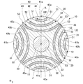
- FIG. 2 is a cross-sectional view showing the rotor of the present embodiment, and is a cross-sectional view taken along the line II-II in FIG.
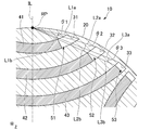
- FIG. 3 is a cross-sectional view showing a part of the rotor of the present embodiment, and is a partially enlarged view of FIG.
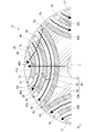
- FIG. 4 is a cross-sectional view for explaining the flow of magnetic flux in the rotor of the present embodiment.
- the Z-axis direction shown in each figure is a vertical direction in which the positive side is the "upper side” and the negative side is the “lower side”.
- the central axis J appropriately shown in each figure is a virtual line that is parallel to the Z-axis direction and extends in the vertical direction.
- the axial direction of the central axis J that is, the direction parallel to the vertical direction
- the radial direction centered on the central axis J is simply referred to as "radial direction”.
- the circumferential direction centered on is simply called the "circumferential direction”.
- the vertical direction, the upper side, and the lower side are simply names for explaining the arrangement relations of each part, and the actual arrangement relations, etc. are the arrangement relations, etc. other than the arrangement relations, etc. indicated by these names. There may be.
- the motor 1 of the present embodiment shown in FIG. 1 is an inner rotor type motor.
- the motor 1 of the present embodiment includes a housing 2, a rotor 10, a stator 3, a bearing holder 4, and bearings 5a and 5b.
- the housing 2 houses the rotor 10, the stator 3, the bearing holder 4, and the bearings 5a and 5b inside.
- the bottom of the housing 2 holds the bearing 5b.
- the bearing holder 4 holds the bearing 5a.
- the bearings 5a and 5b are, for example, ball bearings.
- the stator 3 is located on the outer side in the radial direction of the rotor 10.
- the stator 3 has a stator core 3a, an insulator 3d, and a plurality of coils 3e.
- the stator core 3a has a core back 3b and a plurality of teeth 3c.
- the core back 3b is an annular shape centered on the central axis J.
- the plurality of teeth 3c extend radially inward from the core back 3b. Although not shown, the plurality of teeth 3c are arranged at equal intervals along the circumferential direction.
- the plurality of coils 3e are mounted on the stator core 3a via the insulator 3d.
- the rotor 10 can rotate about the central axis J.
- the rotor 10 includes a shaft 11, a rotor core 20, and a plurality of magnets 40.
- the shaft 11 is a columnar shape extending in the axial direction about the central axis J.
- the shaft 11 is rotatably supported around the central axis J by bearings 5a and 5b.
- the rotor core 20 is a magnetic material.
- the rotor core 20 is fixed to the outer peripheral surface of the shaft 11.
- the rotor core 20 has a through hole 21 that penetrates the rotor core 20 in the axial direction. As shown in FIG. 2, the through hole 21 has a circular shape centered on the central axis J when viewed in the axial direction.
- the shaft 11 is passed through the through hole 21.
- the shaft 11 is fixed in the through hole 21 by, for example, press fitting or the like.
- the rotor core 20 is configured by, for example, a plurality of electromagnetic steel sheets laminated in the axial direction.
- the rotor core 20 has a plurality of slits 30.
- the plurality of slits 30 penetrate the rotor core 20 in the axial direction, for example.
- the plurality of slits 30 extend along a plane orthogonal to the axial direction.
- the plurality of slits 30 include a first slit 31, a second slit 32, and a third slit 33.
- the first slit 31, the second slit 32, and the third slit 33 have an arc shape that is convex inward in the radial direction when viewed in the axial direction.
- the second slit 32 is located apart from the first slit 31 in the radial direction.
- the third slit 33 is located apart from the inside of the second slit 32 in the radial direction.
- the first slit 31, the second slit 32, and the third slit 33 are arranged side by side at equal intervals in the radial direction.
- the first slit 31, the second slit 32, and the third slit 33 are, for example, arcuate shapes that are concentric with each other when viewed in the axial direction.
- the arc radius of the second slit 32 is larger than the arc radius of the first slit 31.
- the arc radius of the third slit 33 is larger than the arc radius of the second slit 32.
- the width of the first slit 31, the width of the second slit 32, and the width of the third slit 33 are, for example, the same as each other.
- a certain parameter is the same as each other includes not only a case where a certain parameter is exactly the same as each other but also a case where a certain parameter is substantially the same as each other.
- the parameters are substantially the same as each other includes, for example, that the parameters are slightly deviated from each other within the tolerance.
- each slit 30 When viewed in the axial direction, the distance between the first slit 31 and the second slit 32 and the distance between the second slit 32 and the third slit 33 are larger than the width of each slit 30.
- the width of each slit 30 is the dimension of each slit 30 in the direction orthogonal to the direction in which each slit 30 extends in an arc shape when viewed in the axial direction.
- the direction in which the slit 30 extends in an arc shape when viewed in the axial direction is referred to as the "stretching direction".
- the direction in which the first slit 31 extends in an arc shape when viewed in the axial direction is referred to as a "first stretching direction”.
- the direction in which the second slit 32 extends in an arc shape when viewed in the axial direction is referred to as a "second stretching direction”.
- the direction in which the third slit 33 extends in an arc shape when viewed in the axial direction is referred to as a "third stretching direction”.
- both ends of the first slit 31, both ends of the second slit 32, and both ends of the third slit 33 are located at the radial outer edges of the rotor core 20.
- Both ends of the first slit 31 are both ends of the first slit 31 in the first stretching direction.
- the both ends of the second slit 32 are both ends of the second slit 32 in the second stretching direction.
- Both ends of the third slit 33 are both ends of the third slit 33 in the third stretching direction.
- Both ends of the first slit 31, both ends of the second slit 32, and both ends of the third slit 33 are located, for example, slightly radially inward from the outer peripheral surface of the rotor core 20.
- the inner side surfaces at both ends of each slit 30 are arranged along the outer peripheral surface of the rotor core 20 when viewed in the axial direction.
- the radial positions of both ends of the first slit 31, the radial positions of both ends of the second slit 32, and the radial positions of both ends of the third slit 33 are the same as each other. Both ends of the first slit 31, both ends of the second slit 32, and both ends of the third slit 33 are arranged side by side at the outer edge of the rotor core 20 in the radial direction at intervals along the circumferential direction. ..
- the dimension of the second slit 32 in the second stretching direction is larger than the dimension of the first slit 31 in the first stretching direction.
- the dimension of the third slit 33 in the third stretching direction is larger than the dimension of the second slit 32 in the second stretching direction.
- first slit 31, the second slit 32, and the third slit 33 are provided along the circumferential direction.
- a plurality of the first slit 31, the second slit 32, and the third slit 33 are provided along the circumferential direction.
- the plurality of first slits 31 are arranged at equal intervals along the circumferential direction.
- the plurality of second slits 32 are arranged at equal intervals over one circumference along the circumferential direction.
- the plurality of third slits 33 are arranged at equal intervals along the circumferential direction.
- Each group including the first slit 31, the second slit 32, and the third slit 33, which are arranged at intervals in the radial direction, is arranged in such a posture that the groups adjacent to each other in the circumferential direction are tilted by 90 ° in the circumferential direction. It has the same configuration except that it is.
- the plurality of magnets 40 are provided in the plurality of slits 30.
- One magnet 40 is provided in each slit 30.
- the magnet 40 is a ferrite magnet.
- the plurality of magnets 40 include a first magnet 41, a second magnet 42, and a third magnet 43.
- the first magnet 41 is provided in the first slit 31.
- the first magnet 41 is provided for each first slit 31.
- four first magnets 41 are provided.
- the first magnet 41 has an arc shape extending along the first slit 31 when viewed in the axial direction.
- the first magnet 41 has an arc shape that is convex inward in the radial direction when viewed in the axial direction.
- the first magnet 41 is fitted in the first slit 31.
- the radial side surfaces of the first magnet 41 are in contact with the radial side surfaces of the first slit 31, respectively.
- both ends of the first magnet 41 are arranged apart from both ends of the first slit 31. Both ends of the first magnet 41 are both ends of the first magnet 41 in the first stretching direction. Both end faces of the first magnet 41 in the first stretching direction are orthogonal to, for example, the first stretching direction.
- First flux barrier portions 51 are provided on both sides of the first magnet 41 in the first stretching direction.
- the first flux barrier portion 51 is a portion of the first slit 31 in which the first magnet 41 is not arranged. In the present embodiment, the first flux barrier portion 51 is a gap portion.
- the first magnet 41 is provided, for example, over the entire axial direction in the first slit 31.
- the second magnet 42 is provided in the second slit 32.
- the second magnet 42 is provided for each second slit 32.
- four second magnets 42 are provided.
- the second magnet 42 has an arc shape extending along the second slit 32 when viewed in the axial direction.
- the second magnet 42 has an arc shape that is convex inward in the radial direction when viewed in the axial direction.
- the second magnet 42 is fitted in the second slit 32.
- the radial side surfaces of the second magnet 42 are in contact with the radial side surfaces of the second slit 32, respectively.
- both ends of the second magnet 42 are arranged apart from both ends of the second slit 32. Both ends of the second magnet 42 are both ends of the second magnet 42 in the second stretching direction. Both end faces of the second magnet 42 in the second stretching direction are orthogonal to, for example, the second stretching direction.
- Second flux barrier portions 52 are provided on both sides of the second magnet 42 in the second stretching direction.
- the second flux barrier portion 52 is a portion of the second slit 32 in which the second magnet 42 is not arranged.
- the second flux barrier portion 52 is a gap portion.
- the dimension of the second flux barrier portion 52 in the second stretching direction is smaller than the dimension of the first flux barrier portion 51 in the first stretching direction.
- the second magnet 42 is provided, for example, over the entire axial direction in the second slit 32.
- the third magnet 43 is provided in the third slit 33.
- the third magnet 43 is provided for each third slit 33.
- four third magnets 43 are provided.
- the third magnet 43 has an arc shape extending along the third slit 33 when viewed in the axial direction.
- the third magnet 43 has an arc shape that is convex inward in the radial direction when viewed in the axial direction.
- the third magnet 43 is fitted in the third slit 33.
- the radial side surfaces of the third magnet 43 are in contact with the radial side surfaces of the third slit 33, respectively.
- Both ends of the third magnet 43 are arranged apart from both ends of the third slit 33. Both ends of the third magnet 43 are both ends of the third magnet 43 in the third stretching direction. Both end faces of the third magnet 43 in the third stretching direction are orthogonal to, for example, the third stretching direction.
- Third flux barrier portions 53 are provided on both sides of the third magnet 43 in the third stretching direction.
- the third flux barrier portion 53 is a portion of the third slit 33 in which the third magnet 43 is not arranged.
- the third flux barrier portion 53 is a gap portion.
- the dimension of the third flux barrier portion 53 in the third stretching direction is smaller than the dimension of the second flux barrier portion 52 in the second stretching direction.
- the third magnet 43 is provided, for example, over the entire axial direction in the third slit 33.
- the magnetic poles of the first magnet 41, the magnetic poles of the second magnet 42, and the magnetic poles of the third magnet 43 are arranged along the radial direction.
- the first magnet 41 includes a first magnet 41a and a first magnet 41b in which magnetic poles are arranged so as to be reversed in the radial direction.
- the first magnet 41a and the first magnet 41b are alternately arranged along the circumferential direction.
- the second magnet 42 includes a second magnet 42a and a second magnet 42b in which the magnetic poles are arranged so as to be radially inverted from each other.
- the second magnet 42a and the second magnet 42b are alternately arranged along the circumferential direction.
- the third magnet 43 includes a third magnet 43a and a third magnet 43b in which the magnetic poles are arranged so as to be reversed in the radial direction.
- the third magnet 43a and the third magnet 43b are alternately arranged along the circumferential direction.
- the first magnet 41a, the second magnet 42a, and the third magnet 43a are the same in each set including the first slit 31, the second slit 32, and the third slit 33, which are arranged at intervals in the radial direction. It is arranged in each slit of the set. As a result, the first magnet 41a, the second magnet 42a, and the third magnet 43a are arranged side by side with an interval in the radial direction.
- the first magnet 41b, the second magnet 42b, and the third magnet 43b are the same in each set including the first slit 31, the second slit 32, and the third slit 33, which are arranged at intervals in the radial direction. It is arranged in each slit of the set. As a result, the first magnet 41b, the second magnet 42b, and the third magnet 43b are arranged side by side with an interval in the radial direction.
- the radial outer portion is the north pole and the radial inner portion is the south pole.
- the radial outer portion is the S pole and the radial inner portion is the N pole.
- the radial outer portion is the S pole
- the radial inner portion is the N pole
- the first magnet 41b and the second magnet are the second.
- the radial outer portion may be the north pole and the radial inner portion may be the south pole.
- the point where the virtual line IL passing through the central axis J, the first slit 31, the second slit 32, and the third slit 33 intersects the outer peripheral surface of the rotor core 20 when viewed in the axial direction is set as the reference point RP.
- the virtual line IL passes through the central axis J, the circumferential center of the first slit 31, the circumferential center of the second slit 32, and the circumferential center of the third slit 33 when viewed in the axial direction. ..
- the virtual line IL passes through, for example, the circumferential center of the first magnet 41, the circumferential center of the second magnet 42, and the circumferential center of the third magnet 43 when viewed in the axial direction.
- the first angle ⁇ 1 formed by is the second angle formed by the line segment L2a connecting the reference point RP and the end of the second slit 32 and the line segment L2b connecting the reference point RP and the end of the second magnet 42. Greater than ⁇ 2.
- the second angle ⁇ 2 is formed by a line segment L3a connecting the reference point RP and the end of the third slit 33 and a line segment L3b connecting the reference point RP and the end of the third magnet 43. It is larger than the third angle ⁇ 3. That is, the first angle ⁇ 1, the second angle ⁇ 2, and the third angle ⁇ 3 satisfy the relationship of ⁇ 1> ⁇ 2> ⁇ 3.
- the line segment L1a connects the reference point RP and one end of the radial outer edge of the first slit 31 in the first extending direction when viewed in the axial direction.
- the line segment L1b connects the reference point RP and one end of the radial outer edge of the first magnet 41 in the first extending direction when viewed in the axial direction.
- the line segment L2a connects the reference point RP and one end of the radial outer edge of the second slit 32 in the second extending direction when viewed in the axial direction.
- the line segment L2b connects the reference point RP and one end of the radial outer edge of the second magnet 42 in the second extending direction when viewed in the axial direction.
- the line segment L3a connects the reference point RP and one end of the radial outer edge of the third slit 33 in the third extension direction when viewed in the axial direction.
- the line segment L3b connects the reference point RP and one end of the radial outer edge of the third magnet 43 in the third extending direction when viewed in the axial direction.
- the line segment L1b, the line segment L2b, and the line segment L3b are provided on the same straight line when viewed in the axial direction, for example.
- the first angle ⁇ 1 is larger than twice the third angle ⁇ 3 and smaller than three times the third angle ⁇ 3.
- the second angle ⁇ 2 is larger than 1.5 times the third angle ⁇ 3 and smaller than 2.5 times the third angle ⁇ 3.
- the torque of the motor 1 can be improved by satisfying the above-mentioned relationship between the first angle ⁇ 1, the second angle ⁇ 2, and the third angle ⁇ 3.
- the magnet 40 is not arranged in the slit 30, the magnetic flux flowing in the rotor core 20 tends to flow in an arc shape along between the plurality of slits 30, as shown by the arrow FB in FIG. This makes it easier for the magnetic flux to flow in the rotor core 20 along the flow of the magnetic flux between the stator 3 and the rotor 10.
- torque is generated to rotate the rotor 10 by the magnetic flux radiated from the stator 3 even when the rotor 10 is not provided with the magnet 40. Can be made to.
- the torque generated between the rotor core 20 and the stator 3 regardless of the magnet 40 is referred to as a reluctance torque.
- the torque for rotating the rotor 10 is also generated by the magnetic force of the magnet 40.
- the torque generated in the rotor 10 by the magnetic force of the magnet 40 is referred to as a magnet torque.
- the rotor 10 generates both reluctance torque and magnet torque.
- the total torque obtained by adding the reluctance torque and the magnet torque is the torque of the motor 1.
- the magnet is arranged in the entire slit 30.
- the magnetic flux radiated from both ends of the magnet tends to return to both ends of the magnet through the rotor core 20 without reaching the stator 3. Therefore, the magnetic flux of the magnet cannot be sufficiently used to improve the torque of the motor. Further, the magnetic flux circulating between both ends of the magnet and the rotor core 20 may disturb the flow of the magnetic flux in other portions. As a result, even if the magnet is simply arranged in the slit 30, the torque of the motor may not be sufficiently improved.
- both ends of each magnet 40 are arranged apart from both ends of each slit 30. Therefore, flux barrier portions are provided on both sides of each magnet 40. More specifically, first flux barrier portions 51 are provided on both sides of the first magnet 41 in the first stretching direction. Second flux barrier portions 52 are provided on both sides of the second magnet 42 in the second stretching direction. Third flux barrier portions 53 are provided on both sides of the third magnet 43 in the third stretching direction. As a result, the magnetic flux radiated from both ends of each magnet 40 is blocked by each flux barrier portion, and the return to both ends of each magnet 40 is suppressed. Therefore, the magnetic flux radiated from the magnet 40 can be sufficiently used to improve the torque of the motor 1. Further, since it is possible to suppress the generation of magnetic flux circulating only between the magnet 40 and the rotor core 20, it is possible to prevent the flow of magnetic flux in other parts from being disturbed.
- the first angle ⁇ 1 is larger than the second angle ⁇ 2, and the second angle ⁇ 2 is larger than the third angle ⁇ 3. Therefore, when viewed in the axial direction, the end portion of the first magnet 41 provided in the first slit 31 is more the outer peripheral surface of the rotor core 20 than the end portion of the second magnet 42 provided in the second slit 32. It is easy to be arranged at a position away from the drawing direction. When viewed in the axial direction, the end of the second magnet 42 provided in the second slit 32 extends from the outer peripheral surface of the rotor core 20 with respect to the end of the third magnet 43 provided in the third slit 33. It is easy to be placed in a position separated in the direction.
- the flow of the magnetic flux radiated from the magnet 40 can be easily brought close to the flow of the magnetic flux that generates the reluctance torque.
- the magnetic flux radiated from the magnet 40 can be suitably flowed between the rotor 10 and the stator 3, and can be easily used to generate the magnet torque. Therefore, the magnet torque can be suitably improved. Therefore, the torque of the motor 1 can be suitably improved.
- the first angle ⁇ 1, the second angle ⁇ 2, and the third angle ⁇ 3 have a relationship opposite to that of the present embodiment, that is, a relationship that satisfies ⁇ 1 ⁇ 2 ⁇ 3, the end of the second magnet.
- the portion is more likely to be arranged at a position farther from the outer peripheral surface of the rotor core in the stretching direction than the end portion of the first magnet, and the end portion of the third magnet is from the outer peripheral surface of the rotor core rather than the end portion of the second magnet. It is easy to be placed at a position separated in the stretching direction.
- the flow of magnetic flux passing through one end of the first magnet in the first stretching direction, one end of the second magnet in the second stretching direction, and one end of the third magnet in the third stretching direction is shown by the arrow MB in FIG. It is easy to approach the flow of magnetic flux shown by. As a result, the flow of the magnetic flux radiated from the magnet tends to be significantly different from the flow of the magnetic flux that causes the reluctance torque. Therefore, it is difficult to sufficiently improve the magnet torque, and the torque of the motor cannot be sufficiently improved.
- both ends in the extending direction of the magnet are located at the outer edges in the radial direction of the rotor core.
- both ends of the magnet in the stretching direction are likely to be demagnetized due to the influence of the magnetic field generated by the stator. Therefore, even if both ends in the stretching direction of the magnet are scraped to provide a flux barrier portion, the total amount of magnetic flux radiated from the magnet is unlikely to be affected. As a result, it is possible to prevent the total amount of magnetic flux radiated from the magnet 40 from being reduced even if the magnets 40 are not provided at both ends of the slit 30 in the stretching direction as in the present embodiment.
- the magnet 40 can be made smaller than the case where the magnet 40 is provided in the entire slit 30. Therefore, the cost for preparing the magnet 40 can be reduced, and the manufacturing cost of the rotor 10 and the manufacturing cost of the motor 1 can be reduced.
- both ends of the first slit 31, both ends of the second slit 32, and both ends of the third slit 33 are located at the radial outer edges of the rotor core 20. Therefore, the portion of the rotor core 20 located between the plurality of slits 30 can be extended in an arc shape from a part of the radial outer edge portion of the rotor core 20 to another part of the radial outer edge portion of the rotor core 20.
- the magnetic flux flowing between the stator 3 and the rotor 10 can be suitably flowed along the plurality of slits 30 in the rotor core 20. Therefore, the reluctance torque can be further improved. Therefore, the torque of the motor 1 can be further improved.
- the radial positions of both ends of the first slit 31, the radial positions of both ends of the second slit 32, and the radial positions of both ends of the third slit 33 are the same as each other. be. Therefore, the magnetic flux can be stably flowed between the plurality of slits 30 in the rotor core 20 as compared with the case where the radial positions of both ends of each slit 30 vary. As a result, the reluctance torque can be further improved. Therefore, the torque of the motor 1 can be further improved.
- a plurality of the first slit 31, the second slit 32, and the third slit 33 are provided along the circumferential direction.
- the first magnet 41 is provided for each of the first slits 31.
- the second magnet 42 is provided for each of the second slits 32.
- the third magnet 43 is provided for each of the third slits 33. Therefore, the reluctance torque and the magnet torque can be further improved. Thereby, the torque of the motor 1 can be further improved.
- the first slit 31, the second slit 32, and the third slit 33 are arranged side by side at equal intervals in the radial direction. Therefore, the ease of flow of magnetic flux between the first slit 31 and the second slit 32 of the rotor core 20 and the ease of flow of magnetic flux between the second slit 32 and the third slit 33 of the rotor core 20 are the same. Can be done to the extent. As a result, the magnetic flux can be suitably passed between the plurality of slits 30 in the rotor core 20, and the reluctance torque can be further improved. Therefore, the torque of the motor 1 can be further improved.
- the first angle ⁇ 1 is larger than twice the third angle ⁇ 3 and smaller than three times the third angle ⁇ 3.
- the first flux barrier portion 51 is suitably made larger, and the magnetic flux radiated from both ends of the first magnet 41 does not pass through the stator 3. It is possible to further suppress the return to the first magnet 41. Thereby, the magnet torque can be further improved.
- the first angle ⁇ 1 smaller than three times the third angle ⁇ 3, it is possible to prevent the dimension of the first magnet 41 in the first stretching direction from becoming too small. As a result, it is possible to suppress a decrease in the amount of magnetic flux radiated from the first magnet 41, and it is possible to suppress a decrease in magnet torque.
- the torque of the motor 1 can be improved more preferably.
- the second angle ⁇ 2 is larger than 1.5 times the third angle ⁇ 3 and smaller than 2.5 times the third angle ⁇ 3.
- the second flux barrier portion 52 is suitably made larger, and the magnetic flux radiated from both ends of the second magnet 42 causes the stator 3. It is possible to further suppress the return to the second magnet 42 without passing through. Thereby, the magnet torque can be further improved.
- the second angle ⁇ 2 smaller than 2.5 times the third angle ⁇ 3, it is possible to prevent the dimension of the second magnet 42 in the second stretching direction from becoming too small. As a result, it is possible to suppress a decrease in the amount of magnetic flux radiated from the second magnet 42, and it is possible to suppress a decrease in magnet torque.
- the torque of the motor 1 can be improved more preferably.
- the magnet 40 is a ferrite magnet. Therefore, as compared with the case where the magnet 40 is a ferrite magnet, demagnetization of the magnet 40 due to the influence of temperature can be suppressed. Thereby, the magnet torque can be preferably obtained. Therefore, the torque of the motor 1 can be improved more preferably.
- the plurality of slits may include other slits as long as they include at least one first slit, a second slit, and a third slit.
- the plurality of slits may include one or more other slits arranged side by side at radial intervals together with the first slit, the second slit, and the third slit.
- the other slit may have an arc shape that is convex inward in the radial direction when viewed in the axial direction.
- the plurality of slits may include slits that are not arcuate when viewed in the axial direction.
- the plurality of slits may include slits in which magnets are not arranged inside. Only three slits, one first slit, one second slit, and one third slit, may be provided.
- the slit does not have to penetrate the rotor core in the axial direction.
- the slit may be opened only on one end face of the end faces on both sides in the axial direction of the rotor core. Both ends of the slit in the extending direction may not be provided on the radial outer edge of the rotor core.
- the width of the first slit, the width of the second slit, and the width of the third slit may be different from each other.
- the dimensions of the first slit in the first stretching direction, the dimensions of the second slit in the second stretching direction, and the dimensions of the third slit in the third stretching direction may be the same as each other.
- the flux barrier portions provided at both ends in the stretching direction of the slit are not particularly limited as long as the flow of magnetic flux can be suppressed.
- the flux barrier portion is a gap portion, but the flux barrier portion may be formed by embedding a non-magnetic material such as resin in the gap portion.
- the type of magnet is not particularly limited.
- the magnet may be a neodymium magnet.
- the plurality of magnets may include a magnet provided in the other slit.
- the first angle ⁇ 1, the second angle ⁇ 2, and the third angle ⁇ 3 are not particularly limited as long as they satisfy the relationship of ⁇ 1> ⁇ 2> ⁇ 3.
- the positions of both ends of the other slits and both ends of the magnet provided in the other slits may be determined along the relationship between the first angle ⁇ 1, the second angle ⁇ 2, and the third angle ⁇ 3.
- the slits and magnets located inward in the radial direction are the lines connecting the reference point and the end of the slit when viewed in the axial direction.
- the angle formed by the minute and the line segment connecting the reference point and the end of the magnet may be large.
- the reference point and the end of the 4th slit are viewed in the axial direction.
- the fourth angle formed by the line segment connecting the above and the line segment connecting the reference point and the end of the fourth magnet may be smaller than the third angle. Further, for example, when the fifth slit located apart from the radial outside of the first slit and the fifth magnet arranged in the fifth slit are provided, the reference point and the end of the fifth slit are viewed in the axial direction.
- the fifth angle formed by the line segment connecting the portions and the line segment connecting the reference point and the end portion of the fifth magnet may be larger than the first angle.
- the application of the motor to which the present invention is applied is not particularly limited.
- the motor may be mounted on a vehicle, for example, or may be mounted on a device other than the vehicle.
- the configurations described in the present specification can be appropriately combined within a range that does not contradict each other.
Landscapes
- Engineering & Computer Science (AREA)
- Power Engineering (AREA)
- Permanent Field Magnets Of Synchronous Machinery (AREA)
Priority Applications (4)
| Application Number | Priority Date | Filing Date | Title |
|---|---|---|---|
| JP2020571878A JPWO2021171663A1 (enExample) | 2020-02-27 | 2020-09-14 | |
| US17/800,079 US12132355B2 (en) | 2020-02-27 | 2020-09-14 | Rotor and motor |
| DE112020006809.9T DE112020006809T5 (de) | 2020-02-27 | 2020-09-14 | Rotor und motor |
| CN202080097546.7A CN115176399A (zh) | 2020-02-27 | 2020-09-14 | 转子和马达 |
Applications Claiming Priority (2)
| Application Number | Priority Date | Filing Date | Title |
|---|---|---|---|
| JP2020-031830 | 2020-02-27 | ||
| JP2020031830 | 2020-02-27 |
Publications (1)
| Publication Number | Publication Date |
|---|---|
| WO2021171663A1 true WO2021171663A1 (ja) | 2021-09-02 |
Family
ID=77489882
Family Applications (1)
| Application Number | Title | Priority Date | Filing Date |
|---|---|---|---|
| PCT/JP2020/034772 Ceased WO2021171663A1 (ja) | 2020-02-27 | 2020-09-14 | ロータ、およびモータ |
Country Status (5)
| Country | Link |
|---|---|
| US (1) | US12132355B2 (enExample) |
| JP (1) | JPWO2021171663A1 (enExample) |
| CN (1) | CN115176399A (enExample) |
| DE (1) | DE112020006809T5 (enExample) |
| WO (1) | WO2021171663A1 (enExample) |
Citations (3)
| Publication number | Priority date | Publication date | Assignee | Title |
|---|---|---|---|---|
| JP2014093914A (ja) * | 2012-11-06 | 2014-05-19 | Mitsuba Corp | ブラシレスモータ |
| JP2015122838A (ja) * | 2013-12-20 | 2015-07-02 | 三菱重工プラスチックテクノロジー株式会社 | モータ |
| WO2018043081A1 (ja) * | 2016-08-31 | 2018-03-08 | 株式会社東芝 | 回転子およびリラクタンスモータ |
Family Cites Families (7)
| Publication number | Priority date | Publication date | Assignee | Title |
|---|---|---|---|---|
| JP3703907B2 (ja) * | 1996-03-18 | 2005-10-05 | アイチエレック株式会社 | ブラシレスdcモータ |
| CN202444346U (zh) * | 2012-03-05 | 2012-09-19 | 珠海格力节能环保制冷技术研究中心有限公司 | 永磁辅助同步磁阻电机转子铁芯及电机 |
| JP2013236419A (ja) * | 2012-05-07 | 2013-11-21 | Daikin Ind Ltd | 回転電気機械 |
| CN104508948B (zh) * | 2012-08-16 | 2017-08-25 | 株式会社美姿把 | 磁铁辅助型磁阻马达用转子和无刷马达 |
| JP2015037331A (ja) * | 2013-08-10 | 2015-02-23 | 株式会社ミツバ | ブラシレスモータ |
| CN204244048U (zh) * | 2014-11-25 | 2015-04-01 | 珠海格力节能环保制冷技术研究中心有限公司 | 电机 |
| JP2018153047A (ja) * | 2017-03-14 | 2018-09-27 | 本田技研工業株式会社 | 回転電機のロータ |
-
2020
- 2020-09-14 JP JP2020571878A patent/JPWO2021171663A1/ja active Pending
- 2020-09-14 DE DE112020006809.9T patent/DE112020006809T5/de active Pending
- 2020-09-14 US US17/800,079 patent/US12132355B2/en active Active
- 2020-09-14 WO PCT/JP2020/034772 patent/WO2021171663A1/ja not_active Ceased
- 2020-09-14 CN CN202080097546.7A patent/CN115176399A/zh not_active Withdrawn
Patent Citations (3)
| Publication number | Priority date | Publication date | Assignee | Title |
|---|---|---|---|---|
| JP2014093914A (ja) * | 2012-11-06 | 2014-05-19 | Mitsuba Corp | ブラシレスモータ |
| JP2015122838A (ja) * | 2013-12-20 | 2015-07-02 | 三菱重工プラスチックテクノロジー株式会社 | モータ |
| WO2018043081A1 (ja) * | 2016-08-31 | 2018-03-08 | 株式会社東芝 | 回転子およびリラクタンスモータ |
Also Published As
| Publication number | Publication date |
|---|---|
| US20230100335A1 (en) | 2023-03-30 |
| US12132355B2 (en) | 2024-10-29 |
| DE112020006809T5 (de) | 2022-12-29 |
| JPWO2021171663A1 (enExample) | 2021-09-02 |
| CN115176399A (zh) | 2022-10-11 |
Similar Documents
| Publication | Publication Date | Title |
|---|---|---|
| JP5714189B2 (ja) | 回転子およびその回転子を備えた回転電機 | |
| JP5709907B2 (ja) | 車両用永久磁石埋込型回転電機 | |
| JP5762569B2 (ja) | 永久磁石埋込型モータの回転子ならびにこれを用いた圧縮機、送風機および冷凍空調装置 | |
| JP2016010176A (ja) | モータ | |
| JP5096756B2 (ja) | 回転電機 | |
| JP6673707B2 (ja) | 埋込磁石型モータ | |
| US9515524B2 (en) | Electric motor | |
| JPWO2020194390A1 (ja) | 回転電機 | |
| WO2021171663A1 (ja) | ロータ、およびモータ | |
| JP6929603B2 (ja) | 回転機 | |
| JP5897939B2 (ja) | ロータ及びモータ | |
| JPWO2020059515A1 (ja) | 回転電機 | |
| CN115882630A (zh) | 旋转电机 | |
| JP6892219B2 (ja) | 回転電機 | |
| WO2021245966A1 (ja) | モータ | |
| JP7600065B2 (ja) | 回転電機 | |
| JP7627201B2 (ja) | 回転電機 | |
| JP5303907B2 (ja) | アキシャルギャップ型回転電機及び界磁子用コア | |
| JP7632471B2 (ja) | 回転電機 | |
| WO2023199709A1 (ja) | 回転電機 | |
| JP2023061074A (ja) | 埋込磁石型モータ | |
| JP2023147770A (ja) | ロータおよび回転電機 | |
| JP2022047760A (ja) | 回転電機 | |
| JP2024165482A (ja) | 回転電機 | |
| WO2022054302A1 (ja) | 回転電機 |
Legal Events
| Date | Code | Title | Description |
|---|---|---|---|
| ENP | Entry into the national phase |
Ref document number: 2020571878 Country of ref document: JP Kind code of ref document: A |
|
| 121 | Ep: the epo has been informed by wipo that ep was designated in this application |
Ref document number: 20920964 Country of ref document: EP Kind code of ref document: A1 |
|
| 122 | Ep: pct application non-entry in european phase |
Ref document number: 20920964 Country of ref document: EP Kind code of ref document: A1 |