WO2021171633A1 - フレーム組立体及びフレーム組立体の製造方法 - Google Patents
フレーム組立体及びフレーム組立体の製造方法 Download PDFInfo
- Publication number
- WO2021171633A1 WO2021171633A1 PCT/JP2020/008560 JP2020008560W WO2021171633A1 WO 2021171633 A1 WO2021171633 A1 WO 2021171633A1 JP 2020008560 W JP2020008560 W JP 2020008560W WO 2021171633 A1 WO2021171633 A1 WO 2021171633A1
- Authority
- WO
- WIPO (PCT)
- Prior art keywords
- frame assembly
- frame
- members
- manufacturing
- fixing
- Prior art date
- Legal status (The legal status is an assumption and is not a legal conclusion. Google has not performed a legal analysis and makes no representation as to the accuracy of the status listed.)
- Ceased
Links
Images


Classifications
-
- B—PERFORMING OPERATIONS; TRANSPORTING
- B64—AIRCRAFT; AVIATION; COSMONAUTICS
- B64C—AEROPLANES; HELICOPTERS
- B64C39/00—Aircraft not otherwise provided for
- B64C39/02—Aircraft not otherwise provided for characterised by special use
- B64C39/024—Aircraft not otherwise provided for characterised by special use of the remote controlled vehicle type, i.e. RPV
-
- B—PERFORMING OPERATIONS; TRANSPORTING
- B64—AIRCRAFT; AVIATION; COSMONAUTICS
- B64U—UNMANNED AERIAL VEHICLES [UAV]; EQUIPMENT THEREFOR
- B64U20/00—Constructional aspects of UAVs
- B64U20/70—Constructional aspects of the UAV body
-
- B—PERFORMING OPERATIONS; TRANSPORTING
- B64—AIRCRAFT; AVIATION; COSMONAUTICS
- B64C—AEROPLANES; HELICOPTERS
- B64C1/00—Fuselages; Constructional features common to fuselages, wings, stabilising surfaces or the like
- B64C1/06—Frames; Stringers; Longerons ; Fuselage sections
-
- B—PERFORMING OPERATIONS; TRANSPORTING
- B64—AIRCRAFT; AVIATION; COSMONAUTICS
- B64C—AEROPLANES; HELICOPTERS
- B64C1/00—Fuselages; Constructional features common to fuselages, wings, stabilising surfaces or the like
- B64C1/06—Frames; Stringers; Longerons ; Fuselage sections
- B64C1/08—Geodetic or other open-frame structures
-
- B—PERFORMING OPERATIONS; TRANSPORTING
- B64—AIRCRAFT; AVIATION; COSMONAUTICS
- B64F—GROUND OR AIRCRAFT-CARRIER-DECK INSTALLATIONS SPECIALLY ADAPTED FOR USE IN CONNECTION WITH AIRCRAFT; DESIGNING, MANUFACTURING, ASSEMBLING, CLEANING, MAINTAINING OR REPAIRING AIRCRAFT, NOT OTHERWISE PROVIDED FOR; HANDLING, TRANSPORTING, TESTING OR INSPECTING AIRCRAFT COMPONENTS, NOT OTHERWISE PROVIDED FOR
- B64F5/00—Designing, manufacturing, assembling, cleaning, maintaining or repairing aircraft, not otherwise provided for; Handling, transporting, testing or inspecting aircraft components, not otherwise provided for
- B64F5/10—Manufacturing or assembling aircraft, e.g. jigs therefor
-
- B—PERFORMING OPERATIONS; TRANSPORTING
- B64—AIRCRAFT; AVIATION; COSMONAUTICS
- B64U—UNMANNED AERIAL VEHICLES [UAV]; EQUIPMENT THEREFOR
- B64U20/00—Constructional aspects of UAVs
- B64U20/60—UAVs characterised by the material
- B64U20/65—Composite materials
-
- B—PERFORMING OPERATIONS; TRANSPORTING
- B64—AIRCRAFT; AVIATION; COSMONAUTICS
- B64U—UNMANNED AERIAL VEHICLES [UAV]; EQUIPMENT THEREFOR
- B64U10/00—Type of UAV
- B64U10/10—Rotorcrafts
- B64U10/13—Flying platforms
-
- F—MECHANICAL ENGINEERING; LIGHTING; HEATING; WEAPONS; BLASTING
- F16—ENGINEERING ELEMENTS AND UNITS; GENERAL MEASURES FOR PRODUCING AND MAINTAINING EFFECTIVE FUNCTIONING OF MACHINES OR INSTALLATIONS; THERMAL INSULATION IN GENERAL
- F16B—DEVICES FOR FASTENING OR SECURING CONSTRUCTIONAL ELEMENTS OR MACHINE PARTS TOGETHER, e.g. NAILS, BOLTS, CIRCLIPS, CLAMPS, CLIPS OR WEDGES; JOINTS OR JOINTING
- F16B5/00—Joining sheets or plates, e.g. panels, to one another or to strips or bars parallel to them
- F16B5/04—Joining sheets or plates, e.g. panels, to one another or to strips or bars parallel to them by means of riveting
-
- Y—GENERAL TAGGING OF NEW TECHNOLOGICAL DEVELOPMENTS; GENERAL TAGGING OF CROSS-SECTIONAL TECHNOLOGIES SPANNING OVER SEVERAL SECTIONS OF THE IPC; TECHNICAL SUBJECTS COVERED BY FORMER USPC CROSS-REFERENCE ART COLLECTIONS [XRACs] AND DIGESTS
- Y02—TECHNOLOGIES OR APPLICATIONS FOR MITIGATION OR ADAPTATION AGAINST CLIMATE CHANGE
- Y02T—CLIMATE CHANGE MITIGATION TECHNOLOGIES RELATED TO TRANSPORTATION
- Y02T50/00—Aeronautics or air transport
- Y02T50/40—Weight reduction
Definitions
- the present invention relates to a frame assembly and a method for manufacturing the frame assembly.
- the flying object is stabilized when equipped with shooting equipment (see Patent Document 1).
- Patent Document 1 cannot eliminate instability due to bending of the frame or the like.
- the present invention has been made in view of such a background, and an object of the present invention is to provide a technique capable of stabilizing the frame of an air vehicle.
- the main invention of the present invention for solving the above problems is a frame assembly for an unmanned aerial vehicle, in which at least two parallel first frame members and a second frame member orthogonal to the first frame member are used. And a fixing member fixed to each of the first and second frame members.
- the frame of the flying object can be stabilized.
- FIG. 2 is a cross-sectional view taken along the line AA of FIG. It is a figure explaining another structural example in a frame assembly 1.
- FIG. It is a figure explaining another structural example in a frame assembly 1.
- FIG. It is a figure explaining another structural example in a frame assembly 1.
- the present invention includes, for example, the following configuration.
- [Item 1] A frame assembly for unmanned aerial vehicles With at least two parallel first frame members, A second frame member orthogonal to the first frame member and A fixing member fixed to each of the first and second frame members, A frame assembly characterized by comprising.
- [Item 2] The frame assembly according to item 1. At least one of the first and second frame members and the fixing member forms an opening in the center of the frame assembly.
- [Item 3] The frame assembly according to item 1.
- the two plate-shaped fixing members sandwich the first and second frame members.
- [Item 4] The frame assembly according to item 3.
- a frame assembly featuring.
- [Item 5] A frame assembly for unmanned aerial vehicles The first and second frame members extending on a plane, A fixing member extending parallel to the plane and fixed to each of the first and second frames.
- a frame assembly characterized by comprising.
- [Item 6] A frame assembly for an unmanned aerial vehicle, characterized in that a plurality of frame members sandwiched between two plate-shaped materials are riveted to the plate-shaped materials.
- [Item 8] A frame assembly for unmanned aerial vehicles, characterized in that the fixing members are riveted to multiple frame members.
- a frame assembly for unmanned aerial vehicles The first and second frame members arranged on a flat surface, A fixing member fixed to each of the first and second frame members, With The fixing member shall be fixed to at least one of the first and second frame members at at least two places.
- a frame assembly featuring. [Item 10] The frame assembly according to item 9. The fixing member is fixed to the first and second frame members by riveting.
- a frame assembly featuring. [Item 11] The frame assembly according to item 9. The two plate-shaped fixing members sandwich the first and second frame members.
- [Item 13] A frame assembly characterized in that a plate-like material is fixed to a plurality of frame members made of carbon fiber reinforced plastic.
- [Item 14] The frame assembly according to item 13.
- the plate-shaped material is riveted to each of the frame members.
- [Item 15] The frame assembly according to item 13. That the two plate-shaped members sandwich the frame member,
- [Item 16] The frame assembly according to item 15. The opening is provided only in one of the plate-shaped materials.
- [Item 17] A method of manufacturing a frame assembly for an unmanned aerial vehicle. Fixing the fixing member to each of at least two parallel first frame members and a second frame member orthogonal to the first frame member.
- [Item 18] The method for manufacturing a frame assembly according to item 17. Arranging the first and second frame members and at least one of the fixing members so as to form an opening in the central portion of the frame assembly.
- [Item 19] The method for manufacturing a frame assembly according to item 17. To sandwich the first and second frame members between the two plate-shaped fixing members.
- [Item 20] The method for manufacturing a frame assembly according to item 19. Providing an opening only in one of the fixing members, A method of manufacturing a frame assembly characterized by.
- [Item 21] A method of manufacturing a frame assembly for an unmanned aerial vehicle.
- [Item 22] A method for manufacturing a frame assembly for an unmanned aerial vehicle, which comprises riveting a plurality of frame members sandwiched between two plate-shaped materials to the plate-shaped material.
- [Item 23] The method for manufacturing a frame assembly according to item 22. Providing an opening only in one of the plate-shaped materials, A method of manufacturing a frame assembly characterized by.
- [Item 24] A method of manufacturing a frame assembly for an unmanned aerial vehicle, which comprises riveting a fixing member to a plurality of frame members.
- [Item 25] A method of manufacturing a frame assembly for an unmanned aerial vehicle.
- [Item 29] A method for manufacturing a frame assembly, which comprises fixing a plate-like material to a plurality of frame members made of carbon fiber reinforced plastic.
- [Item 30] The method for manufacturing a frame assembly according to item 29. Riveting the plate-like material to each of the frame members, A method of manufacturing a frame assembly characterized by.
- [Item 31] The method for manufacturing a frame assembly according to item 29. To sandwich the frame member between the two plate-shaped materials, A method of manufacturing a frame assembly characterized by.
- [Item 32] The method for manufacturing a frame assembly according to item 31. Providing an opening only in one of the plate-shaped materials, A method of manufacturing a frame assembly characterized by.
- the frame assembly 1 of the present embodiment includes a structure for fixing a fixing member to a plurality of frame members.
- the material of the frame member is, for example, CFRP (Carbon Fiber Reinforced Plastic; carbon fiber reinforced plastic).
- the material of the fixing member can be CFRP.
- the rigidity of the frame assembly 1 can be ensured by forming the fixing member into a plate shape and fixing it to a plurality of frame members. Further, the rigidity of the frame assembly 1 may be ensured by passing a rod-shaped fixing member as a brace between a plurality of frame members.
- the fixing member can be riveted to the frame member.
- a mechanism such as a clamp can be omitted, and the weight of the frame assembly 1 can be reduced.
- Two rivets can be arranged for one frame member.
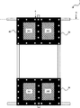
- FIG. 1 is a top view of the frame assembly 1 of the present embodiment.
- the frame assembly 1 of the example of FIG. 1 can be used for an unmanned aerial vehicle flying with the direction of arrow F as the forward direction.
- the frame assembly 1 includes two parallel frame members 211 and 212 extending in the left-right direction perpendicular to the front-rear direction.
- Frame members 221 and 222 parallel to each other in the front-rear direction are arranged at one end of the frame members 211 and 212.
- frame members 223 and 224 parallel to the front-rear direction are arranged.
- frame members 225 and 226 extending in parallel in the front-rear direction apart from the ends of the frame members 211 and 211 are provided.
- the frame members 213 and 214 which are parallel to each other in the left-right direction may be provided from the frame members 225 and 226 toward the outside of the frame assembly 1, respectively.
- Plate-shaped fixing members 31 and 32 are arranged at the left and right ends of the frame assembly 1.
- the fixing member 31 is fixed to the frame members 211, 212, 213, 221, 222, 215 by the rivet 40, respectively.
- the fixing member 31 is riveted at a plurality of positions on the frame members 211, 212, 213, 221 and 222, 215, respectively.
- the fixing member 32 is fixed to the frame members 211, 212, 214, 223, 224, and 216 by rivets 40 at a plurality of positions, respectively.
- An opening 11 is formed in the central portion of the frame assembly 1. When the frame assembly 1 is used for an air vehicle, various payloads can be arranged in the opening 11.
- FIG. 2 is a top view of the frame assembly 1 of the present embodiment.
- the fixing members 33 and 34 are further arranged so as to oppose the fixing members 31 and 32 of the frame assembly 1 shown in FIG.
- Frame members 211, 212, 213, 221, 222, 225 are sandwiched by the fixing members 31 and 33.
- the fixing members 32 and 34 sandwich the frame members 211, 212, 223, 224, 226.
- the fixing member 33 is fixed to each of the frame members 211, 212, 213, 222, 222, and 225 at a plurality of locations by the rivet 40.
- the fixing member 34 is also fixed at a plurality of positions by the rivet 40 to each of the frame members 211, 212, 223, 224, and 226.
- FIG. 3 is a cross-sectional view taken along the line AA of FIG. It is shown that the fixing members 31 and 33 are fixed to the frame member 222 by rivets 40, and are also fixed to the frame member 213 by rivets 40.
- the end portion of each frame member may be separated from other frame members, and in the example of FIG. 3, a gap 12 is provided between the end portion 2221 of the frame member 222 and the frame member 213.
- the fixing member 33 is provided with openings 331 and 332. Therefore, in the top view of FIG. 2, the fixing member 31 can be visually recognized from the openings 331 and 332.
- the frame members are also provided with openings 341 and 342, and the fixing member 32 can be visually recognized from above the frame assembly 1 through the openings 341 and 342.
- a control mechanism or the like can be arranged in the openings 331, 332, 341, 342.
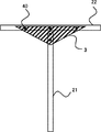
- FIG. 4 is a diagram illustrating another configuration example in the frame assembly 1.
- the fixing member 3 for fixing the plurality of frame members 21 and 22 can be a triangle instead of a rectangle. Further, the fixing member 3 can have an arbitrary shape. Here, too, the fixing member 3 is fixed to each of the frame members 21 and 22 by the rivets 40 and by riveting at a plurality of places.
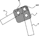
- FIG. 5 is a diagram illustrating another configuration example in the frame assembly 1.
- the longitudinal directions of the plurality of frame members 21 and 22 do not have to be vertical.
- the fixing member 3 is riveted at a plurality of places by the frame members 21 and 22 and the rivets 40, respectively.
- the end portions of a part or all of the frame members may be fixed to other frame members.
- Frame assembly 3 Fixing members 21, 22 Frame members 31 to 34 Fixing members 40 Rivets 211 to 213 Frame members 221-226 Frame members
Landscapes
- Engineering & Computer Science (AREA)
- Aviation & Aerospace Engineering (AREA)
- Mechanical Engineering (AREA)
- Manufacturing & Machinery (AREA)
- Remote Sensing (AREA)
- Transportation (AREA)
- General Engineering & Computer Science (AREA)
- Chemical & Material Sciences (AREA)
- Composite Materials (AREA)
- Materials Engineering (AREA)
- Connection Of Plates (AREA)
- Body Structure For Vehicles (AREA)
- Toys (AREA)
- Tents Or Canopies (AREA)
Priority Applications (8)
| Application Number | Priority Date | Filing Date | Title |
|---|---|---|---|
| JP2021503625A JP6868317B1 (ja) | 2020-02-29 | 2020-02-29 | フレーム組立体及びフレーム組立体の製造方法 |
| PCT/JP2020/008560 WO2021171633A1 (ja) | 2020-02-29 | 2020-02-29 | フレーム組立体及びフレーム組立体の製造方法 |
| US17/794,554 US12195180B2 (en) | 2020-02-29 | 2020-02-29 | Frame assembly and method for manufacturing same |
| EP20921249.7A EP4112456A4 (en) | 2020-02-29 | 2020-02-29 | CHASSIS ASSEMBLY AND ITS MANUFACTURING METHOD |
| CN202120426834.4U CN222408555U (zh) | 2020-02-29 | 2021-02-26 | 框架组装体 |
| CN202110219585.6A CN113320677A (zh) | 2020-02-29 | 2021-02-26 | 框架组装体以及框架组装体的制造方法 |
| JP2021034734A JP6905779B1 (ja) | 2020-02-29 | 2021-03-04 | フレーム組立体及びフレーム組立体の製造方法 |
| JP2021102119A JP7610261B2 (ja) | 2020-02-29 | 2021-06-21 | フレーム組立体及びフレーム組立体の製造方法 |
Applications Claiming Priority (1)
| Application Number | Priority Date | Filing Date | Title |
|---|---|---|---|
| PCT/JP2020/008560 WO2021171633A1 (ja) | 2020-02-29 | 2020-02-29 | フレーム組立体及びフレーム組立体の製造方法 |
Publications (1)
| Publication Number | Publication Date |
|---|---|
| WO2021171633A1 true WO2021171633A1 (ja) | 2021-09-02 |
Family
ID=75801820
Family Applications (1)
| Application Number | Title | Priority Date | Filing Date |
|---|---|---|---|
| PCT/JP2020/008560 Ceased WO2021171633A1 (ja) | 2020-02-29 | 2020-02-29 | フレーム組立体及びフレーム組立体の製造方法 |
Country Status (5)
| Country | Link |
|---|---|
| US (1) | US12195180B2 (enExample) |
| EP (1) | EP4112456A4 (enExample) |
| JP (3) | JP6868317B1 (enExample) |
| CN (2) | CN222408555U (enExample) |
| WO (1) | WO2021171633A1 (enExample) |
Cited By (1)
| Publication number | Priority date | Publication date | Assignee | Title |
|---|---|---|---|---|
| US20210362823A1 (en) * | 2020-05-21 | 2021-11-25 | North West Heli-Structures Incorporated | Panel systems and methods for helicopters |
Families Citing this family (2)
| Publication number | Priority date | Publication date | Assignee | Title |
|---|---|---|---|---|
| JPWO2022224630A1 (enExample) * | 2021-04-23 | 2022-10-27 | ||
| EP4228966A4 (en) * | 2021-12-31 | 2023-11-01 | Istanbul Gelisim Üniversitesi | Coaxial aluminum sigma drone chassis |
Citations (4)
| Publication number | Priority date | Publication date | Assignee | Title |
|---|---|---|---|---|
| JP2017519297A (ja) * | 2014-06-25 | 2017-07-13 | アマゾン テクノロジーズ インコーポレイテッド | 自動航空機のための物体回避 |
| JP2017532256A (ja) * | 2014-11-11 | 2017-11-02 | アマゾン テクノロジーズ インコーポレイテッド | 長期飛行のための無人航空機構成 |
| JP2019191585A (ja) | 2019-04-26 | 2019-10-31 | エスゼット ディージェイアイ オスモ テクノロジー カンパニー リミテッドSZ DJI Osmo Technology Co., Ltd. | 安定化と振動低減のための装置および方法 |
| WO2020017488A1 (ja) * | 2018-07-17 | 2020-01-23 | 株式会社プロドローン | 無人航空機 |
Family Cites Families (32)
| Publication number | Priority date | Publication date | Assignee | Title |
|---|---|---|---|---|
| US3623936A (en) * | 1967-07-20 | 1971-11-30 | United States Steel Corp | Honeycomb core construction for panels |
| US4761930A (en) * | 1981-12-14 | 1988-08-09 | Fibergrate Corporation | Grating system |
| DE102004063205B3 (de) | 2004-12-23 | 2006-05-04 | Julian Kuntz | Fluggerät mit verbesserter Beweglichkeit am Boden |
| EP2121439B1 (en) * | 2007-02-16 | 2012-11-14 | Donald Orval Shaw | Modular flying vehicle |
| FR2912804B1 (fr) * | 2007-02-21 | 2010-10-01 | Sogeclair | Dispositif de montage d'equipements non dimensionnants sur une ossature structurelle d'un vehicule, vehicule equipe d'un tel dispositif et procede de montage. |
| JP4793998B2 (ja) * | 2007-03-05 | 2011-10-12 | 株式会社Lixil | フレーム |
| US8079549B2 (en) * | 2008-06-30 | 2011-12-20 | EMBRAER—Empresa Brasileira de Aeronautica S.A. | Monolithic integrated structural panels especially useful for aircraft structures |
| FR2936219B1 (fr) * | 2008-09-23 | 2010-09-17 | Airbus France | Structure de fuselage pour fixation combinee de matelas d'isolation et d'equipements, aeronef incorporant une telle structure. |
| EP2530010B1 (en) * | 2011-06-02 | 2013-09-18 | Bell Helicopter Textron Inc. | Integrally stiffened panel |
| WO2015094059A1 (en) * | 2013-12-20 | 2015-06-25 | Saab Ab | Stiffening element and reinforced structure |
| EP2889212B1 (en) * | 2013-12-30 | 2016-01-06 | AIRBUS HELICOPTERS DEUTSCHLAND GmbH | Subfloor structure with an integral hull for a rotary wing aircraft |
| EP2942269B1 (en) * | 2014-05-06 | 2018-09-26 | Airbus Operations GmbH | Method for manufacturing a load bearing structure and such a load bearing structure |
| CN112722240A (zh) * | 2015-06-01 | 2021-04-30 | 深圳市大疆创新科技有限公司 | 无人飞行器 |
| US9657489B2 (en) * | 2015-06-15 | 2017-05-23 | The Boeing Company | Fractal stiffening |
| KR101692315B1 (ko) | 2015-06-17 | 2017-01-03 | 이상현 | 멀티 로터 비행체 |
| CN105059526B (zh) | 2015-07-29 | 2018-02-09 | 北京中科遥数信息技术有限公司 | 一种滑竿式的轻型四旋翼无人机 |
| CN105775151A (zh) | 2016-01-29 | 2016-07-20 | 上海云舞网络科技有限公司 | 360°全景航拍摄影摄像无人机及机架框 |
| US10266245B2 (en) * | 2016-04-06 | 2019-04-23 | Harris Aerial Llc | Folding heavy-lift unmanned aerial vehicle frame |
| WO2017183551A1 (ja) * | 2016-04-19 | 2017-10-26 | 株式会社プロドローン | 無人航空機 |
| US11142311B2 (en) * | 2016-07-01 | 2021-10-12 | Textron Innovations Inc. | VTOL aircraft for external load operations |
| US10183746B2 (en) * | 2016-07-01 | 2019-01-22 | Bell Helicopter Textron Inc. | Aircraft with independently controllable propulsion assemblies |
| CN106043679B (zh) | 2016-07-28 | 2018-09-07 | 易瓦特科技股份公司 | 多轴动力源无人飞行设备 |
| EP3281861B1 (en) * | 2016-08-11 | 2019-10-02 | AIRBUS HELICOPTERS DEUTSCHLAND GmbH | A rotary wing aircraft with a fuselage that comprises at least one structural stiffened panel |
| US10183747B1 (en) * | 2016-08-26 | 2019-01-22 | Kitty Hawk Corporation | Multicopter with boom-mounted rotors |
| CN106995052B (zh) | 2017-03-23 | 2020-01-24 | 沈阳无距科技有限公司 | 多轴无人机 |
| WO2018225112A1 (ja) * | 2017-06-04 | 2018-12-13 | 株式会社エアロネクスト | 飛行体 |
| EP3678933A4 (en) * | 2017-09-09 | 2021-05-19 | Ideaforge Technology Pvt. Ltd. | NON-PLANAR FRAMEWORK STRUCTURE OF AN UNMANNED AIRCRAFT |
| KR101883346B1 (ko) | 2017-11-03 | 2018-07-30 | 이상현 | 비행체 |
| JP7175511B2 (ja) | 2018-02-07 | 2022-11-21 | 国立大学法人大阪大学 | マルチコプタシステム及び荷物の受け渡し方法 |
| US20190283856A1 (en) * | 2018-03-13 | 2019-09-19 | Spirit Aerosystems, Inc. | Panel structure of optimally constructed and subsequently integrated components and method of making same |
| CN210618446U (zh) * | 2019-09-10 | 2020-05-26 | 苏州创飞智能科技有限公司 | 一种轻量化无人机 |
| CN110697021A (zh) * | 2019-10-24 | 2020-01-17 | 中国人民解放军军事科学院国防工程研究院 | 一种轻量化折叠无人机 |
-
2020
- 2020-02-29 US US17/794,554 patent/US12195180B2/en active Active
- 2020-02-29 WO PCT/JP2020/008560 patent/WO2021171633A1/ja not_active Ceased
- 2020-02-29 JP JP2021503625A patent/JP6868317B1/ja active Active
- 2020-02-29 EP EP20921249.7A patent/EP4112456A4/en not_active Withdrawn
-
2021
- 2021-02-26 CN CN202120426834.4U patent/CN222408555U/zh active Active
- 2021-02-26 CN CN202110219585.6A patent/CN113320677A/zh active Pending
- 2021-03-04 JP JP2021034734A patent/JP6905779B1/ja active Active
- 2021-06-21 JP JP2021102119A patent/JP7610261B2/ja active Active
Patent Citations (4)
| Publication number | Priority date | Publication date | Assignee | Title |
|---|---|---|---|---|
| JP2017519297A (ja) * | 2014-06-25 | 2017-07-13 | アマゾン テクノロジーズ インコーポレイテッド | 自動航空機のための物体回避 |
| JP2017532256A (ja) * | 2014-11-11 | 2017-11-02 | アマゾン テクノロジーズ インコーポレイテッド | 長期飛行のための無人航空機構成 |
| WO2020017488A1 (ja) * | 2018-07-17 | 2020-01-23 | 株式会社プロドローン | 無人航空機 |
| JP2019191585A (ja) | 2019-04-26 | 2019-10-31 | エスゼット ディージェイアイ オスモ テクノロジー カンパニー リミテッドSZ DJI Osmo Technology Co., Ltd. | 安定化と振動低減のための装置および方法 |
Non-Patent Citations (1)
| Title |
|---|
| See also references of EP4112456A4 |
Cited By (2)
| Publication number | Priority date | Publication date | Assignee | Title |
|---|---|---|---|---|
| US20210362823A1 (en) * | 2020-05-21 | 2021-11-25 | North West Heli-Structures Incorporated | Panel systems and methods for helicopters |
| US11613340B2 (en) * | 2020-05-21 | 2023-03-28 | North West Heli-Structures Incorporated | Panel systems and methods for helicopters |
Also Published As
| Publication number | Publication date |
|---|---|
| CN222408555U (zh) | 2025-01-28 |
| JP2021155042A (ja) | 2021-10-07 |
| CN113320677A (zh) | 2021-08-31 |
| US12195180B2 (en) | 2025-01-14 |
| JPWO2021171633A1 (enExample) | 2021-09-02 |
| JP6905779B1 (ja) | 2021-07-21 |
| US20230083990A1 (en) | 2023-03-16 |
| JP2021138364A (ja) | 2021-09-16 |
| JP7610261B2 (ja) | 2025-01-08 |
| EP4112456A1 (en) | 2023-01-04 |
| EP4112456A4 (en) | 2023-10-18 |
| JP6868317B1 (ja) | 2021-05-12 |
Similar Documents
| Publication | Publication Date | Title |
|---|---|---|
| JP6905779B1 (ja) | フレーム組立体及びフレーム組立体の製造方法 | |
| JP2017206238A (ja) | 航空機翼移動装置 | |
| US20180354602A1 (en) | Fuselage to wing attachment | |
| US10647440B2 (en) | Assembly for an aircraft comprising an engine of the “open rotor puller” type and means for attaching the latter to the rigid structure of an attachment pylon | |
| EP2709902B1 (en) | Aft-loading aircraft with-twin t-tail assembly | |
| US9452818B2 (en) | Aircraft comprising a wing box and a fuselage provided with a connecting device connected to the wing box | |
| US10099784B1 (en) | Frame for rotary wing aircraft | |
| US10556666B2 (en) | Aircraft with strut-braced wing system | |
| US12473071B2 (en) | Frame assembly and method for manufacturing frame assembly | |
| US20210107618A1 (en) | Single Butt Line Keel and Roof Beam | |
| EP3235722B1 (en) | Hat section door frame with integral gussets | |
| WO2022224630A1 (ja) | フレーム組立体及びフレーム組立体の製造方法 | |
| US20160144901A1 (en) | Vehicle body arrangement for a vehicle front part | |
| US20090218445A1 (en) | Airframe attachment fitting | |
| JP6839284B2 (ja) | 回転翼航空機の降着装置 | |
| KR101591408B1 (ko) | 무인항공기용 영상감지기 거치장치 | |
| KR101483097B1 (ko) | 항공기 도어 조립을 위한 치공구 | |
| CN113665825A (zh) | 包括两个连杆和中间加强件的组件、包括至少一个该组件的飞机发动机架 | |
| CN120135516A (zh) | 一种超大展弦比无人机机翼结构及具有其的无人机 | |
| JP2025130202A (ja) | 飛行体 | |
| KR20250165943A (ko) | 경량형 고정익 드론 | |
| JP1728839S (ja) | 無人航空機 | |
| JP1716585S (ja) | 無人航空機用フレーム | |
| WO2019000545A1 (zh) | 一种无人机及其固定翼 |
Legal Events
| Date | Code | Title | Description |
|---|---|---|---|
| ENP | Entry into the national phase |
Ref document number: 2021503625 Country of ref document: JP Kind code of ref document: A |
|
| 121 | Ep: the epo has been informed by wipo that ep was designated in this application |
Ref document number: 20921249 Country of ref document: EP Kind code of ref document: A1 |
|
| ENP | Entry into the national phase |
Ref document number: 2020921249 Country of ref document: EP Effective date: 20220929 |
|
| NENP | Non-entry into the national phase |
Ref country code: DE |
|
| WWW | Wipo information: withdrawn in national office |
Ref document number: 2020921249 Country of ref document: EP |