WO2021167091A1 - 接着剤組成物層、積層体、光学積層体および光学装置、ならびに光学積層体の製造方法 - Google Patents
接着剤組成物層、積層体、光学積層体および光学装置、ならびに光学積層体の製造方法 Download PDFInfo
- Publication number
- WO2021167091A1 WO2021167091A1 PCT/JP2021/006453 JP2021006453W WO2021167091A1 WO 2021167091 A1 WO2021167091 A1 WO 2021167091A1 JP 2021006453 W JP2021006453 W JP 2021006453W WO 2021167091 A1 WO2021167091 A1 WO 2021167091A1
- Authority
- WO
- WIPO (PCT)
- Prior art keywords
- adhesive composition
- mass
- curable resin
- adhesive
- optical
- Prior art date
Links
- 239000000853 adhesive Substances 0.000 title claims abstract description 292
- 230000001070 adhesive effect Effects 0.000 title claims abstract description 292
- 239000000203 mixture Substances 0.000 title claims abstract description 237
- 230000003287 optical effect Effects 0.000 title claims description 243
- 238000004519 manufacturing process Methods 0.000 title claims description 21
- 229920005989 resin Polymers 0.000 claims abstract description 127
- 239000011347 resin Substances 0.000 claims abstract description 125
- 239000000178 monomer Substances 0.000 claims abstract description 86
- NIXOWILDQLNWCW-UHFFFAOYSA-M Acrylate Chemical compound [O-]C(=O)C=C NIXOWILDQLNWCW-UHFFFAOYSA-M 0.000 claims abstract description 81
- 229920000642 polymer Polymers 0.000 claims abstract description 28
- 125000000524 functional group Chemical group 0.000 claims abstract description 15
- 229920001577 copolymer Polymers 0.000 claims abstract description 14
- 229920002554 vinyl polymer Polymers 0.000 claims abstract description 12
- 239000012790 adhesive layer Substances 0.000 claims description 137
- 239000010410 layer Substances 0.000 claims description 134
- 239000003999 initiator Substances 0.000 claims description 22
- 239000000463 material Substances 0.000 claims description 22
- 239000004926 polymethyl methacrylate Substances 0.000 claims description 19
- 229920003229 poly(methyl methacrylate) Polymers 0.000 claims description 18
- 238000005096 rolling process Methods 0.000 claims description 16
- 125000003178 carboxy group Chemical group [H]OC(*)=O 0.000 claims description 13
- 238000000034 method Methods 0.000 claims description 11
- 238000010030 laminating Methods 0.000 claims description 10
- 125000002887 hydroxy group Chemical group [H]O* 0.000 claims description 8
- 229920000578 graft copolymer Polymers 0.000 claims description 6
- 239000000243 solution Substances 0.000 description 51
- 229920000058 polyacrylate Polymers 0.000 description 48
- 230000000052 comparative effect Effects 0.000 description 46
- 239000003431 cross linking reagent Substances 0.000 description 41
- -1 2-ethylhexyl Chemical group 0.000 description 39
- 229920002799 BoPET Polymers 0.000 description 32
- XLPJNCYCZORXHG-UHFFFAOYSA-N 1-morpholin-4-ylprop-2-en-1-one Chemical compound C=CC(=O)N1CCOCC1 XLPJNCYCZORXHG-UHFFFAOYSA-N 0.000 description 27
- NIXOWILDQLNWCW-UHFFFAOYSA-N acrylic acid group Chemical group C(C=C)(=O)O NIXOWILDQLNWCW-UHFFFAOYSA-N 0.000 description 25
- CQEYYJKEWSMYFG-UHFFFAOYSA-N butyl acrylate Chemical compound CCCCOC(=O)C=C CQEYYJKEWSMYFG-UHFFFAOYSA-N 0.000 description 24
- 238000009792 diffusion process Methods 0.000 description 23
- 238000002360 preparation method Methods 0.000 description 21
- 238000002834 transmittance Methods 0.000 description 21
- XEKOWRVHYACXOJ-UHFFFAOYSA-N Ethyl acetate Chemical compound CCOC(C)=O XEKOWRVHYACXOJ-UHFFFAOYSA-N 0.000 description 18
- 239000004925 Acrylic resin Substances 0.000 description 17
- 238000007493 shaping process Methods 0.000 description 15
- 125000000217 alkyl group Chemical group 0.000 description 14
- 239000012948 isocyanate Substances 0.000 description 14
- RTZKZFJDLAIYFH-UHFFFAOYSA-N Diethyl ether Chemical compound CCOCC RTZKZFJDLAIYFH-UHFFFAOYSA-N 0.000 description 13
- 239000004593 Epoxy Substances 0.000 description 13
- 238000012360 testing method Methods 0.000 description 13
- 229920000178 Acrylic resin Polymers 0.000 description 12
- 239000000126 substance Substances 0.000 description 12
- 150000002978 peroxides Chemical class 0.000 description 11
- 229920000139 polyethylene terephthalate Polymers 0.000 description 11
- 239000005020 polyethylene terephthalate Substances 0.000 description 11
- SMZOUWXMTYCWNB-UHFFFAOYSA-N 2-(2-methoxy-5-methylphenyl)ethanamine Chemical compound COC1=CC=C(C)C=C1CCN SMZOUWXMTYCWNB-UHFFFAOYSA-N 0.000 description 10
- NDWUBGAGUCISDV-UHFFFAOYSA-N 4-hydroxybutyl prop-2-enoate Chemical compound OCCCCOC(=O)C=C NDWUBGAGUCISDV-UHFFFAOYSA-N 0.000 description 10
- 206010040844 Skin exfoliation Diseases 0.000 description 10
- 239000003795 chemical substances by application Substances 0.000 description 10
- 150000002513 isocyanates Chemical class 0.000 description 10
- QJGQUHMNIGDVPM-UHFFFAOYSA-N nitrogen group Chemical group [N] QJGQUHMNIGDVPM-UHFFFAOYSA-N 0.000 description 10
- 239000007789 gas Substances 0.000 description 9
- UHESRSKEBRADOO-UHFFFAOYSA-N ethyl carbamate;prop-2-enoic acid Chemical compound OC(=O)C=C.CCOC(N)=O UHESRSKEBRADOO-UHFFFAOYSA-N 0.000 description 8
- 238000011156 evaluation Methods 0.000 description 8
- 238000002156 mixing Methods 0.000 description 8
- 239000007787 solid Substances 0.000 description 8
- 239000002904 solvent Substances 0.000 description 8
- KWVGIHKZDCUPEU-UHFFFAOYSA-N 2,2-dimethoxy-2-phenylacetophenone Chemical compound C=1C=CC=CC=1C(OC)(OC)C(=O)C1=CC=CC=C1 KWVGIHKZDCUPEU-UHFFFAOYSA-N 0.000 description 7
- 125000003647 acryloyl group Chemical group O=C([*])C([H])=C([H])[H] 0.000 description 7
- 238000004132 cross linking Methods 0.000 description 7
- 229920001296 polysiloxane Polymers 0.000 description 7
- HASUCEDGKYJBDC-UHFFFAOYSA-N 1-[3-[[bis(oxiran-2-ylmethyl)amino]methyl]cyclohexyl]-n,n-bis(oxiran-2-ylmethyl)methanamine Chemical compound C1OC1CN(CC1CC(CN(CC2OC2)CC2OC2)CCC1)CC1CO1 HASUCEDGKYJBDC-UHFFFAOYSA-N 0.000 description 6
- 238000001035 drying Methods 0.000 description 6
- 230000001678 irradiating effect Effects 0.000 description 6
- 238000005259 measurement Methods 0.000 description 6
- 239000005057 Hexamethylene diisocyanate Substances 0.000 description 5
- RRAMGCGOFNQTLD-UHFFFAOYSA-N hexamethylene diisocyanate Chemical compound O=C=NCCCCCCN=C=O RRAMGCGOFNQTLD-UHFFFAOYSA-N 0.000 description 5
- 229910052751 metal Inorganic materials 0.000 description 5
- 239000002184 metal Substances 0.000 description 5
- 229920000728 polyester Polymers 0.000 description 5
- 239000003505 polymerization initiator Substances 0.000 description 5
- BFKJFAAPBSQJPD-UHFFFAOYSA-N tetrafluoroethene Chemical group FC(F)=C(F)F BFKJFAAPBSQJPD-UHFFFAOYSA-N 0.000 description 5
- JOYRKODLDBILNP-UHFFFAOYSA-N Ethyl urethane Chemical compound CCOC(N)=O JOYRKODLDBILNP-UHFFFAOYSA-N 0.000 description 4
- ZJCCRDAZUWHFQH-UHFFFAOYSA-N Trimethylolpropane Chemical compound CCC(CO)(CO)CO ZJCCRDAZUWHFQH-UHFFFAOYSA-N 0.000 description 4
- 230000015572 biosynthetic process Effects 0.000 description 4
- 125000004432 carbon atom Chemical group C* 0.000 description 4
- 230000004927 fusion Effects 0.000 description 4
- 229910052757 nitrogen Inorganic materials 0.000 description 4
- 230000035515 penetration Effects 0.000 description 4
- 229920001228 polyisocyanate Polymers 0.000 description 4
- 239000005056 polyisocyanate Substances 0.000 description 4
- TXBCBTDQIULDIA-UHFFFAOYSA-N 2-[[3-hydroxy-2,2-bis(hydroxymethyl)propoxy]methyl]-2-(hydroxymethyl)propane-1,3-diol Chemical compound OCC(CO)(CO)COCC(CO)(CO)CO TXBCBTDQIULDIA-UHFFFAOYSA-N 0.000 description 3
- WEVYAHXRMPXWCK-UHFFFAOYSA-N Acetonitrile Chemical compound CC#N WEVYAHXRMPXWCK-UHFFFAOYSA-N 0.000 description 3
- IJGRMHOSHXDMSA-UHFFFAOYSA-N Atomic nitrogen Chemical compound N#N IJGRMHOSHXDMSA-UHFFFAOYSA-N 0.000 description 3
- PEDCQBHIVMGVHV-UHFFFAOYSA-N Glycerine Chemical compound OCC(O)CO PEDCQBHIVMGVHV-UHFFFAOYSA-N 0.000 description 3
- CERQOIWHTDAKMF-UHFFFAOYSA-N Methacrylic acid Chemical compound CC(=C)C(O)=O CERQOIWHTDAKMF-UHFFFAOYSA-N 0.000 description 3
- 239000004820 Pressure-sensitive adhesive Substances 0.000 description 3
- 239000013522 chelant Substances 0.000 description 3
- 238000006243 chemical reaction Methods 0.000 description 3
- 238000007334 copolymerization reaction Methods 0.000 description 3
- 238000000354 decomposition reaction Methods 0.000 description 3
- 238000009826 distribution Methods 0.000 description 3
- 150000002148 esters Chemical class 0.000 description 3
- 238000010438 heat treatment Methods 0.000 description 3
- 238000004128 high performance liquid chromatography Methods 0.000 description 3
- 238000007654 immersion Methods 0.000 description 3
- 239000004922 lacquer Substances 0.000 description 3
- 150000002894 organic compounds Chemical class 0.000 description 3
- WXZMFSXDPGVJKK-UHFFFAOYSA-N pentaerythritol Chemical compound OCC(CO)(CO)CO WXZMFSXDPGVJKK-UHFFFAOYSA-N 0.000 description 3
- 239000004417 polycarbonate Substances 0.000 description 3
- 229920000515 polycarbonate Polymers 0.000 description 3
- 239000011148 porous material Substances 0.000 description 3
- DVKJHBMWWAPEIU-UHFFFAOYSA-N toluene 2,4-diisocyanate Chemical compound CC1=CC=C(N=C=O)C=C1N=C=O DVKJHBMWWAPEIU-UHFFFAOYSA-N 0.000 description 3
- 125000000391 vinyl group Chemical group [H]C([*])=C([H])[H] 0.000 description 3
- NOBYOEQUFMGXBP-UHFFFAOYSA-N (4-tert-butylcyclohexyl) (4-tert-butylcyclohexyl)oxycarbonyloxy carbonate Chemical compound C1CC(C(C)(C)C)CCC1OC(=O)OOC(=O)OC1CCC(C(C)(C)C)CC1 NOBYOEQUFMGXBP-UHFFFAOYSA-N 0.000 description 2
- FKTHNVSLHLHISI-UHFFFAOYSA-N 1,2-bis(isocyanatomethyl)benzene Chemical compound O=C=NCC1=CC=CC=C1CN=C=O FKTHNVSLHLHISI-UHFFFAOYSA-N 0.000 description 2
- JWYVGKFDLWWQJX-UHFFFAOYSA-N 1-ethenylazepan-2-one Chemical compound C=CN1CCCCCC1=O JWYVGKFDLWWQJX-UHFFFAOYSA-N 0.000 description 2
- LZHUBCULTHIFNO-UHFFFAOYSA-N 2,4-dihydroxy-1,5-bis[4-(2-hydroxyethoxy)phenyl]-2,4-dimethylpentan-3-one Chemical compound C=1C=C(OCCO)C=CC=1CC(C)(O)C(=O)C(O)(C)CC1=CC=C(OCCO)C=C1 LZHUBCULTHIFNO-UHFFFAOYSA-N 0.000 description 2
- OZAIFHULBGXAKX-UHFFFAOYSA-N 2-(2-cyanopropan-2-yldiazenyl)-2-methylpropanenitrile Chemical compound N#CC(C)(C)N=NC(C)(C)C#N OZAIFHULBGXAKX-UHFFFAOYSA-N 0.000 description 2
- AOBIOSPNXBMOAT-UHFFFAOYSA-N 2-[2-(oxiran-2-ylmethoxy)ethoxymethyl]oxirane Chemical compound C1OC1COCCOCC1CO1 AOBIOSPNXBMOAT-UHFFFAOYSA-N 0.000 description 2
- KWOLFJPFCHCOCG-UHFFFAOYSA-N Acetophenone Chemical compound CC(=O)C1=CC=CC=C1 KWOLFJPFCHCOCG-UHFFFAOYSA-N 0.000 description 2
- OMPJBNCRMGITSC-UHFFFAOYSA-N Benzoylperoxide Chemical compound C=1C=CC=CC=1C(=O)OOC(=O)C1=CC=CC=C1 OMPJBNCRMGITSC-UHFFFAOYSA-N 0.000 description 2
- 239000004971 Cross linker Substances 0.000 description 2
- XDTMQSROBMDMFD-UHFFFAOYSA-N Cyclohexane Chemical compound C1CCCCC1 XDTMQSROBMDMFD-UHFFFAOYSA-N 0.000 description 2
- VZCYOOQTPOCHFL-OWOJBTEDSA-N Fumaric acid Chemical compound OC(=O)\C=C\C(O)=O VZCYOOQTPOCHFL-OWOJBTEDSA-N 0.000 description 2
- 239000005058 Isophorone diisocyanate Substances 0.000 description 2
- YIVJZNGAASQVEM-UHFFFAOYSA-N Lauroyl peroxide Chemical compound CCCCCCCCCCCC(=O)OOC(=O)CCCCCCCCCCC YIVJZNGAASQVEM-UHFFFAOYSA-N 0.000 description 2
- WHNWPMSKXPGLAX-UHFFFAOYSA-N N-Vinyl-2-pyrrolidone Chemical compound C=CN1CCCC1=O WHNWPMSKXPGLAX-UHFFFAOYSA-N 0.000 description 2
- ATUOYWHBWRKTHZ-UHFFFAOYSA-N Propane Chemical compound CCC ATUOYWHBWRKTHZ-UHFFFAOYSA-N 0.000 description 2
- 150000001252 acrylic acid derivatives Chemical class 0.000 description 2
- 229910052782 aluminium Inorganic materials 0.000 description 2
- 125000004429 atom Chemical group 0.000 description 2
- ISAOCJYIOMOJEB-UHFFFAOYSA-N benzoin Chemical compound C=1C=CC=CC=1C(O)C(=O)C1=CC=CC=C1 ISAOCJYIOMOJEB-UHFFFAOYSA-N 0.000 description 2
- RWCCWEUUXYIKHB-UHFFFAOYSA-N benzophenone Chemical compound C=1C=CC=CC=1C(=O)C1=CC=CC=C1 RWCCWEUUXYIKHB-UHFFFAOYSA-N 0.000 description 2
- 239000012965 benzophenone Substances 0.000 description 2
- 235000019400 benzoyl peroxide Nutrition 0.000 description 2
- 230000005540 biological transmission Effects 0.000 description 2
- IISBACLAFKSPIT-UHFFFAOYSA-N bisphenol A Chemical compound C=1C=C(O)C=CC=1C(C)(C)C1=CC=C(O)C=C1 IISBACLAFKSPIT-UHFFFAOYSA-N 0.000 description 2
- 150000001732 carboxylic acid derivatives Chemical class 0.000 description 2
- 150000001875 compounds Chemical class 0.000 description 2
- 230000006835 compression Effects 0.000 description 2
- 238000007906 compression Methods 0.000 description 2
- 229910001873 dinitrogen Inorganic materials 0.000 description 2
- 230000000694 effects Effects 0.000 description 2
- 125000003700 epoxy group Chemical group 0.000 description 2
- 239000003822 epoxy resin Substances 0.000 description 2
- 239000011521 glass Substances 0.000 description 2
- IQPQWNKOIGAROB-UHFFFAOYSA-N isocyanate group Chemical group [N-]=C=O IQPQWNKOIGAROB-UHFFFAOYSA-N 0.000 description 2
- 125000001972 isopentyl group Chemical group [H]C([H])([H])C([H])(C([H])([H])[H])C([H])([H])C([H])([H])* 0.000 description 2
- NIMLQBUJDJZYEJ-UHFFFAOYSA-N isophorone diisocyanate Chemical compound CC1(C)CC(N=C=O)CC(C)(CN=C=O)C1 NIMLQBUJDJZYEJ-UHFFFAOYSA-N 0.000 description 2
- QSHDDOUJBYECFT-UHFFFAOYSA-N mercury Chemical compound [Hg] QSHDDOUJBYECFT-UHFFFAOYSA-N 0.000 description 2
- 229910052753 mercury Inorganic materials 0.000 description 2
- XNGIFLGASWRNHJ-UHFFFAOYSA-N phthalic acid Chemical compound OC(=O)C1=CC=CC=C1C(O)=O XNGIFLGASWRNHJ-UHFFFAOYSA-N 0.000 description 2
- 229920000647 polyepoxide Polymers 0.000 description 2
- 238000006116 polymerization reaction Methods 0.000 description 2
- 229920005862 polyol Polymers 0.000 description 2
- 150000003077 polyols Chemical class 0.000 description 2
- 230000002265 prevention Effects 0.000 description 2
- 238000003756 stirring Methods 0.000 description 2
- 229920005992 thermoplastic resin Polymers 0.000 description 2
- 229920001187 thermosetting polymer Polymers 0.000 description 2
- YRHRIQCWCFGUEQ-UHFFFAOYSA-N thioxanthen-9-one Chemical compound C1=CC=C2C(=O)C3=CC=CC=C3SC2=C1 YRHRIQCWCFGUEQ-UHFFFAOYSA-N 0.000 description 2
- VZCYOOQTPOCHFL-UHFFFAOYSA-N trans-butenedioic acid Natural products OC(=O)C=CC(O)=O VZCYOOQTPOCHFL-UHFFFAOYSA-N 0.000 description 2
- DTGKSKDOIYIVQL-WEDXCCLWSA-N (+)-borneol Chemical group C1C[C@@]2(C)[C@@H](O)C[C@@H]1C2(C)C DTGKSKDOIYIVQL-WEDXCCLWSA-N 0.000 description 1
- HJIAMFHSAAEUKR-UHFFFAOYSA-N (2-hydroxyphenyl)-phenylmethanone Chemical compound OC1=CC=CC=C1C(=O)C1=CC=CC=C1 HJIAMFHSAAEUKR-UHFFFAOYSA-N 0.000 description 1
- JNYAEWCLZODPBN-JGWLITMVSA-N (2r,3r,4s)-2-[(1r)-1,2-dihydroxyethyl]oxolane-3,4-diol Chemical compound OC[C@@H](O)[C@H]1OC[C@H](O)[C@H]1O JNYAEWCLZODPBN-JGWLITMVSA-N 0.000 description 1
- AGKBXKFWMQLFGZ-UHFFFAOYSA-N (4-methylbenzoyl) 4-methylbenzenecarboperoxoate Chemical compound C1=CC(C)=CC=C1C(=O)OOC(=O)C1=CC=C(C)C=C1 AGKBXKFWMQLFGZ-UHFFFAOYSA-N 0.000 description 1
- VBQCFYPTKHCPGI-UHFFFAOYSA-N 1,1-bis(2-methylpentan-2-ylperoxy)cyclohexane Chemical compound CCCC(C)(C)OOC1(OOC(C)(C)CCC)CCCCC1 VBQCFYPTKHCPGI-UHFFFAOYSA-N 0.000 description 1
- OTKCEEWUXHVZQI-UHFFFAOYSA-N 1,2-diphenylethanone Chemical compound C=1C=CC=CC=1C(=O)CC1=CC=CC=C1 OTKCEEWUXHVZQI-UHFFFAOYSA-N 0.000 description 1
- OVBFMUAFNIIQAL-UHFFFAOYSA-N 1,4-diisocyanatobutane Chemical compound O=C=NCCCCN=C=O OVBFMUAFNIIQAL-UHFFFAOYSA-N 0.000 description 1
- VNQXSTWCDUXYEZ-UHFFFAOYSA-N 1,7,7-trimethylbicyclo[2.2.1]heptane-2,3-dione Chemical compound C1CC2(C)C(=O)C(=O)C1C2(C)C VNQXSTWCDUXYEZ-UHFFFAOYSA-N 0.000 description 1
- DKEGCUDAFWNSSO-UHFFFAOYSA-N 1,8-dibromooctane Chemical compound BrCCCCCCCCBr DKEGCUDAFWNSSO-UHFFFAOYSA-N 0.000 description 1
- UWFRVQVNYNPBEF-UHFFFAOYSA-N 1-(2,4-dimethylphenyl)propan-1-one Chemical compound CCC(=O)C1=CC=C(C)C=C1C UWFRVQVNYNPBEF-UHFFFAOYSA-N 0.000 description 1
- AYMDJPGTQFHDSA-UHFFFAOYSA-N 1-(2-ethenoxyethoxy)-2-ethoxyethane Chemical compound CCOCCOCCOC=C AYMDJPGTQFHDSA-UHFFFAOYSA-N 0.000 description 1
- MLKIVXXYTZKNMI-UHFFFAOYSA-N 1-(4-dodecylphenyl)-2-hydroxy-2-methylpropan-1-one Chemical compound CCCCCCCCCCCCC1=CC=C(C(=O)C(C)(C)O)C=C1 MLKIVXXYTZKNMI-UHFFFAOYSA-N 0.000 description 1
- YEUIMZOJSJEGFM-UHFFFAOYSA-N 1-cyclohexyl-n,n-bis(oxiran-2-ylmethyl)methanamine Chemical compound C1OC1CN(CC1CCCCC1)CC1CO1 YEUIMZOJSJEGFM-UHFFFAOYSA-N 0.000 description 1
- 239000012956 1-hydroxycyclohexylphenyl-ketone Substances 0.000 description 1
- YIKSHDNOAYSSPX-UHFFFAOYSA-N 1-propan-2-ylthioxanthen-9-one Chemical compound S1C2=CC=CC=C2C(=O)C2=C1C=CC=C2C(C)C YIKSHDNOAYSSPX-UHFFFAOYSA-N 0.000 description 1
- PIZHFBODNLEQBL-UHFFFAOYSA-N 2,2-diethoxy-1-phenylethanone Chemical compound CCOC(OCC)C(=O)C1=CC=CC=C1 PIZHFBODNLEQBL-UHFFFAOYSA-N 0.000 description 1
- IVIDDMGBRCPGLJ-UHFFFAOYSA-N 2,3-bis(oxiran-2-ylmethoxy)propan-1-ol Chemical compound C1OC1COC(CO)COCC1CO1 IVIDDMGBRCPGLJ-UHFFFAOYSA-N 0.000 description 1
- DPGYCJUCJYUHTM-UHFFFAOYSA-N 2,4,4-trimethylpentan-2-yloxy 2-ethylhexaneperoxoate Chemical compound CCCCC(CC)C(=O)OOOC(C)(C)CC(C)(C)C DPGYCJUCJYUHTM-UHFFFAOYSA-N 0.000 description 1
- BRKORVYTKKLNKX-UHFFFAOYSA-N 2,4-di(propan-2-yl)thioxanthen-9-one Chemical compound C1=CC=C2C(=O)C3=CC(C(C)C)=CC(C(C)C)=C3SC2=C1 BRKORVYTKKLNKX-UHFFFAOYSA-N 0.000 description 1
- BTJPUDCSZVCXFQ-UHFFFAOYSA-N 2,4-diethylthioxanthen-9-one Chemical compound C1=CC=C2C(=O)C3=CC(CC)=CC(CC)=C3SC2=C1 BTJPUDCSZVCXFQ-UHFFFAOYSA-N 0.000 description 1
- KQSMCAVKSJWMSI-UHFFFAOYSA-N 2,4-dimethyl-1-n,1-n,3-n,3-n-tetrakis(oxiran-2-ylmethyl)benzene-1,3-diamine Chemical compound CC1=C(N(CC2OC2)CC2OC2)C(C)=CC=C1N(CC1OC1)CC1CO1 KQSMCAVKSJWMSI-UHFFFAOYSA-N 0.000 description 1
- LCHAFMWSFCONOO-UHFFFAOYSA-N 2,4-dimethylthioxanthen-9-one Chemical compound C1=CC=C2C(=O)C3=CC(C)=CC(C)=C3SC2=C1 LCHAFMWSFCONOO-UHFFFAOYSA-N 0.000 description 1
- JAHNSTQSQJOJLO-UHFFFAOYSA-N 2-(3-fluorophenyl)-1h-imidazole Chemical compound FC1=CC=CC(C=2NC=CN=2)=C1 JAHNSTQSQJOJLO-UHFFFAOYSA-N 0.000 description 1
- IMSODMZESSGVBE-UHFFFAOYSA-N 2-Oxazoline Chemical compound C1CN=CO1 IMSODMZESSGVBE-UHFFFAOYSA-N 0.000 description 1
- SYEWHONLFGZGLK-UHFFFAOYSA-N 2-[1,3-bis(oxiran-2-ylmethoxy)propan-2-yloxymethyl]oxirane Chemical compound C1OC1COCC(OCC1OC1)COCC1CO1 SYEWHONLFGZGLK-UHFFFAOYSA-N 0.000 description 1
- HDPLHDGYGLENEI-UHFFFAOYSA-N 2-[1-(oxiran-2-ylmethoxy)propan-2-yloxymethyl]oxirane Chemical compound C1OC1COC(C)COCC1CO1 HDPLHDGYGLENEI-UHFFFAOYSA-N 0.000 description 1
- LCZVSXRMYJUNFX-UHFFFAOYSA-N 2-[2-(2-hydroxypropoxy)propoxy]propan-1-ol Chemical compound CC(O)COC(C)COC(C)CO LCZVSXRMYJUNFX-UHFFFAOYSA-N 0.000 description 1
- WTYYGFLRBWMFRY-UHFFFAOYSA-N 2-[6-(oxiran-2-ylmethoxy)hexoxymethyl]oxirane Chemical compound C1OC1COCCCCCCOCC1CO1 WTYYGFLRBWMFRY-UHFFFAOYSA-N 0.000 description 1
- KUAUJXBLDYVELT-UHFFFAOYSA-N 2-[[2,2-dimethyl-3-(oxiran-2-ylmethoxy)propoxy]methyl]oxirane Chemical compound C1OC1COCC(C)(C)COCC1CO1 KUAUJXBLDYVELT-UHFFFAOYSA-N 0.000 description 1
- AGXAFZNONAXBOS-UHFFFAOYSA-N 2-[[3-(oxiran-2-ylmethyl)phenyl]methyl]oxirane Chemical compound C=1C=CC(CC2OC2)=CC=1CC1CO1 AGXAFZNONAXBOS-UHFFFAOYSA-N 0.000 description 1
- FGTYTUFKXYPTML-UHFFFAOYSA-N 2-benzoylbenzoic acid Chemical compound OC(=O)C1=CC=CC=C1C(=O)C1=CC=CC=C1 FGTYTUFKXYPTML-UHFFFAOYSA-N 0.000 description 1
- ZCDADJXRUCOCJE-UHFFFAOYSA-N 2-chlorothioxanthen-9-one Chemical compound C1=CC=C2C(=O)C3=CC(Cl)=CC=C3SC2=C1 ZCDADJXRUCOCJE-UHFFFAOYSA-N 0.000 description 1
- KMNCBSZOIQAUFX-UHFFFAOYSA-N 2-ethoxy-1,2-diphenylethanone Chemical compound C=1C=CC=CC=1C(OCC)C(=O)C1=CC=CC=C1 KMNCBSZOIQAUFX-UHFFFAOYSA-N 0.000 description 1
- SJEBAWHUJDUKQK-UHFFFAOYSA-N 2-ethylanthraquinone Chemical compound C1=CC=C2C(=O)C3=CC(CC)=CC=C3C(=O)C2=C1 SJEBAWHUJDUKQK-UHFFFAOYSA-N 0.000 description 1
- ZACVGCNKGYYQHA-UHFFFAOYSA-N 2-ethylhexoxycarbonyloxy 2-ethylhexyl carbonate Chemical compound CCCCC(CC)COC(=O)OOC(=O)OCC(CC)CCCC ZACVGCNKGYYQHA-UHFFFAOYSA-N 0.000 description 1
- KRFFWELOYNJROH-UHFFFAOYSA-N 2-hydroxy-1,2-diphenylethanone Chemical compound C=1C=CC=CC=1C(O)C(=O)C1=CC=CC=C1.C=1C=CC=CC=1C(O)C(=O)C1=CC=CC=C1 KRFFWELOYNJROH-UHFFFAOYSA-N 0.000 description 1
- QPXVRLXJHPTCPW-UHFFFAOYSA-N 2-hydroxy-2-methyl-1-(4-propan-2-ylphenyl)propan-1-one Chemical compound CC(C)C1=CC=C(C(=O)C(C)(C)O)C=C1 QPXVRLXJHPTCPW-UHFFFAOYSA-N 0.000 description 1
- XMLYCEVDHLAQEL-UHFFFAOYSA-N 2-hydroxy-2-methyl-1-phenylpropan-1-one Chemical compound CC(C)(O)C(=O)C1=CC=CC=C1 XMLYCEVDHLAQEL-UHFFFAOYSA-N 0.000 description 1
- BQZJOQXSCSZQPS-UHFFFAOYSA-N 2-methoxy-1,2-diphenylethanone Chemical compound C=1C=CC=CC=1C(OC)C(=O)C1=CC=CC=C1 BQZJOQXSCSZQPS-UHFFFAOYSA-N 0.000 description 1
- RTEZVHMDMFEURJ-UHFFFAOYSA-N 2-methylpentan-2-yl 2,2-dimethylpropaneperoxoate Chemical compound CCCC(C)(C)OOC(=O)C(C)(C)C RTEZVHMDMFEURJ-UHFFFAOYSA-N 0.000 description 1
- MYISVPVWAQRUTL-UHFFFAOYSA-N 2-methylthioxanthen-9-one Chemical compound C1=CC=C2C(=O)C3=CC(C)=CC=C3SC2=C1 MYISVPVWAQRUTL-UHFFFAOYSA-N 0.000 description 1
- 125000003903 2-propenyl group Chemical group [H]C([*])([H])C([H])=C([H])[H] 0.000 description 1
- RDFQSFOGKVZWKF-UHFFFAOYSA-N 3-hydroxy-2,2-dimethylpropanoic acid Chemical compound OCC(C)(C)C(O)=O RDFQSFOGKVZWKF-UHFFFAOYSA-N 0.000 description 1
- QOXOZONBQWIKDA-UHFFFAOYSA-N 3-hydroxypropyl Chemical group [CH2]CCO QOXOZONBQWIKDA-UHFFFAOYSA-N 0.000 description 1
- UPMLOUAZCHDJJD-UHFFFAOYSA-N 4,4'-Diphenylmethane Diisocyanate Chemical compound C1=CC(N=C=O)=CC=C1CC1=CC=C(N=C=O)C=C1 UPMLOUAZCHDJJD-UHFFFAOYSA-N 0.000 description 1
- HMBNQNDUEFFFNZ-UHFFFAOYSA-N 4-ethenoxybutan-1-ol Chemical compound OCCCCOC=C HMBNQNDUEFFFNZ-UHFFFAOYSA-N 0.000 description 1
- SXIFAEWFOJETOA-UHFFFAOYSA-N 4-hydroxy-butyl Chemical group [CH2]CCCO SXIFAEWFOJETOA-UHFFFAOYSA-N 0.000 description 1
- FJNCXZZQNBKEJT-UHFFFAOYSA-N 8beta-hydroxymarrubiin Natural products O1C(=O)C2(C)CCCC3(C)C2C1CC(C)(O)C3(O)CCC=1C=COC=1 FJNCXZZQNBKEJT-UHFFFAOYSA-N 0.000 description 1
- 229920006353 Acrylite® Polymers 0.000 description 1
- NOWKCMXCCJGMRR-UHFFFAOYSA-N Aziridine Chemical compound C1CN1 NOWKCMXCCJGMRR-UHFFFAOYSA-N 0.000 description 1
- LCFVJGUPQDGYKZ-UHFFFAOYSA-N Bisphenol A diglycidyl ether Chemical compound C=1C=C(OCC2OC2)C=CC=1C(C)(C)C(C=C1)=CC=C1OCC1CO1 LCFVJGUPQDGYKZ-UHFFFAOYSA-N 0.000 description 1
- FBPFZTCFMRRESA-FSIIMWSLSA-N D-Glucitol Natural products OC[C@H](O)[C@H](O)[C@@H](O)[C@H](O)CO FBPFZTCFMRRESA-FSIIMWSLSA-N 0.000 description 1
- FBPFZTCFMRRESA-JGWLITMVSA-N D-glucitol Chemical compound OC[C@H](O)[C@@H](O)[C@H](O)[C@H](O)CO FBPFZTCFMRRESA-JGWLITMVSA-N 0.000 description 1
- SJIXRGNQPBQWMK-UHFFFAOYSA-N DEAEMA Natural products CCN(CC)CCOC(=O)C(C)=C SJIXRGNQPBQWMK-UHFFFAOYSA-N 0.000 description 1
- ZAFNJMIOTHYJRJ-UHFFFAOYSA-N Diisopropyl ether Chemical compound CC(C)OC(C)C ZAFNJMIOTHYJRJ-UHFFFAOYSA-N 0.000 description 1
- VGGSQFUCUMXWEO-UHFFFAOYSA-N Ethene Chemical compound C=C VGGSQFUCUMXWEO-UHFFFAOYSA-N 0.000 description 1
- 239000005977 Ethylene Substances 0.000 description 1
- YCKRFDGAMUMZLT-UHFFFAOYSA-N Fluorine atom Chemical compound [F] YCKRFDGAMUMZLT-UHFFFAOYSA-N 0.000 description 1
- 229920000877 Melamine resin Polymers 0.000 description 1
- CERQOIWHTDAKMF-UHFFFAOYSA-M Methacrylate Chemical compound CC(=C)C([O-])=O CERQOIWHTDAKMF-UHFFFAOYSA-M 0.000 description 1
- BWPYBAJTDILQPY-UHFFFAOYSA-N Methoxyphenone Chemical compound C1=C(C)C(OC)=CC=C1C(=O)C1=CC=CC(C)=C1 BWPYBAJTDILQPY-UHFFFAOYSA-N 0.000 description 1
- NQSMEZJWJJVYOI-UHFFFAOYSA-N Methyl 2-benzoylbenzoate Chemical compound COC(=O)C1=CC=CC=C1C(=O)C1=CC=CC=C1 NQSMEZJWJJVYOI-UHFFFAOYSA-N 0.000 description 1
- YNAVUWVOSKDBBP-UHFFFAOYSA-N Morpholine Chemical compound C1COCCN1 YNAVUWVOSKDBBP-UHFFFAOYSA-N 0.000 description 1
- 240000007594 Oryza sativa Species 0.000 description 1
- 235000007164 Oryza sativa Nutrition 0.000 description 1
- 229920000538 Poly[(phenyl isocyanate)-co-formaldehyde] Polymers 0.000 description 1
- 239000002202 Polyethylene glycol Substances 0.000 description 1
- 239000004721 Polyphenylene oxide Substances 0.000 description 1
- OFOBLEOULBTSOW-UHFFFAOYSA-N Propanedioic acid Natural products OC(=O)CC(O)=O OFOBLEOULBTSOW-UHFFFAOYSA-N 0.000 description 1
- BLRPTPMANUNPDV-UHFFFAOYSA-N Silane Chemical compound [SiH4] BLRPTPMANUNPDV-UHFFFAOYSA-N 0.000 description 1
- 244000028419 Styrax benzoin Species 0.000 description 1
- 235000000126 Styrax benzoin Nutrition 0.000 description 1
- 235000008411 Sumatra benzointree Nutrition 0.000 description 1
- 230000003213 activating effect Effects 0.000 description 1
- 238000007792 addition Methods 0.000 description 1
- 125000001931 aliphatic group Chemical group 0.000 description 1
- 125000005907 alkyl ester group Chemical group 0.000 description 1
- 150000005215 alkyl ethers Chemical class 0.000 description 1
- 125000005037 alkyl phenyl group Chemical group 0.000 description 1
- XAGFODPZIPBFFR-UHFFFAOYSA-N aluminium Chemical compound [Al] XAGFODPZIPBFFR-UHFFFAOYSA-N 0.000 description 1
- 238000004458 analytical method Methods 0.000 description 1
- 229920005601 base polymer Polymers 0.000 description 1
- 229960002130 benzoin Drugs 0.000 description 1
- 125000001797 benzyl group Chemical group [H]C1=C([H])C([H])=C(C([H])=C1[H])C([H])([H])* 0.000 description 1
- KBWLNCUTNDKMPN-UHFFFAOYSA-N bis(oxiran-2-ylmethyl) hexanedioate Chemical compound C1OC1COC(=O)CCCCC(=O)OCC1CO1 KBWLNCUTNDKMPN-UHFFFAOYSA-N 0.000 description 1
- MQDJYUACMFCOFT-UHFFFAOYSA-N bis[2-(1-hydroxycyclohexyl)phenyl]methanone Chemical compound C=1C=CC=C(C(=O)C=2C(=CC=CC=2)C2(O)CCCCC2)C=1C1(O)CCCCC1 MQDJYUACMFCOFT-UHFFFAOYSA-N 0.000 description 1
- 239000002981 blocking agent Substances 0.000 description 1
- 229930006711 bornane-2,3-dione Natural products 0.000 description 1
- NSGQRLUGQNBHLD-UHFFFAOYSA-N butan-2-yl butan-2-yloxycarbonyloxy carbonate Chemical compound CCC(C)OC(=O)OOC(=O)OC(C)CC NSGQRLUGQNBHLD-UHFFFAOYSA-N 0.000 description 1
- 229910052791 calcium Inorganic materials 0.000 description 1
- 239000003054 catalyst Substances 0.000 description 1
- 229910052804 chromium Inorganic materials 0.000 description 1
- 229910052802 copper Inorganic materials 0.000 description 1
- 238000002788 crimping Methods 0.000 description 1
- LDHQCZJRKDOVOX-NSCUHMNNSA-N crotonic acid Chemical compound C\C=C\C(O)=O LDHQCZJRKDOVOX-NSCUHMNNSA-N 0.000 description 1
- 150000004292 cyclic ethers Chemical group 0.000 description 1
- 125000000113 cyclohexyl group Chemical group [H]C1([H])C([H])([H])C([H])([H])C([H])(*)C([H])([H])C1([H])[H] 0.000 description 1
- 238000013461 design Methods 0.000 description 1
- 150000004985 diamines Chemical class 0.000 description 1
- 235000014113 dietary fatty acids Nutrition 0.000 description 1
- GYZLOYUZLJXAJU-UHFFFAOYSA-N diglycidyl ether Chemical compound C1OC1COCC1CO1 GYZLOYUZLJXAJU-UHFFFAOYSA-N 0.000 description 1
- 239000006185 dispersion Substances 0.000 description 1
- 238000010894 electron beam technology Methods 0.000 description 1
- 238000007720 emulsion polymerization reaction Methods 0.000 description 1
- 238000000605 extraction Methods 0.000 description 1
- 239000000194 fatty acid Substances 0.000 description 1
- 229930195729 fatty acid Natural products 0.000 description 1
- 150000004665 fatty acids Chemical class 0.000 description 1
- HJUFTIJOISQSKQ-UHFFFAOYSA-N fenoxycarb Chemical compound C1=CC(OCCNC(=O)OCC)=CC=C1OC1=CC=CC=C1 HJUFTIJOISQSKQ-UHFFFAOYSA-N 0.000 description 1
- 238000001914 filtration Methods 0.000 description 1
- 239000011737 fluorine Substances 0.000 description 1
- 229910052731 fluorine Inorganic materials 0.000 description 1
- 239000001530 fumaric acid Substances 0.000 description 1
- 235000011187 glycerol Nutrition 0.000 description 1
- 125000003055 glycidyl group Chemical group C(C1CO1)* 0.000 description 1
- 235000019382 gum benzoic Nutrition 0.000 description 1
- 125000003187 heptyl group Chemical group [H]C([*])([H])C([H])([H])C([H])([H])C([H])([H])C([H])([H])C([H])([H])C([H])([H])[H] 0.000 description 1
- 125000004051 hexyl group Chemical group [H]C([H])([H])C([H])([H])C([H])([H])C([H])([H])C([H])([H])C([H])([H])* 0.000 description 1
- 125000004356 hydroxy functional group Chemical group O* 0.000 description 1
- 125000002768 hydroxyalkyl group Chemical group 0.000 description 1
- 229910052738 indium Inorganic materials 0.000 description 1
- 230000009545 invasion Effects 0.000 description 1
- 229910052742 iron Inorganic materials 0.000 description 1
- 125000000959 isobutyl group Chemical group [H]C([H])([H])C([H])(C([H])([H])[H])C([H])([H])* 0.000 description 1
- 229910052749 magnesium Inorganic materials 0.000 description 1
- VZCYOOQTPOCHFL-UPHRSURJSA-N maleic acid Chemical compound OC(=O)\C=C/C(O)=O VZCYOOQTPOCHFL-UPHRSURJSA-N 0.000 description 1
- 239000011976 maleic acid Substances 0.000 description 1
- 229910052748 manganese Inorganic materials 0.000 description 1
- JDSHMPZPIAZGSV-UHFFFAOYSA-N melamine Chemical compound NC1=NC(N)=NC(N)=N1 JDSHMPZPIAZGSV-UHFFFAOYSA-N 0.000 description 1
- 239000012528 membrane Substances 0.000 description 1
- 229910001507 metal halide Inorganic materials 0.000 description 1
- 150000005309 metal halides Chemical class 0.000 description 1
- LVHBHZANLOWSRM-UHFFFAOYSA-N methylenebutanedioic acid Natural products OC(=O)CC(=C)C(O)=O LVHBHZANLOWSRM-UHFFFAOYSA-N 0.000 description 1
- 125000002816 methylsulfanyl group Chemical group [H]C([H])([H])S[*] 0.000 description 1
- JAYXSROKFZAHRQ-UHFFFAOYSA-N n,n-bis(oxiran-2-ylmethyl)aniline Chemical compound C1OC1CN(C=1C=CC=CC=1)CC1CO1 JAYXSROKFZAHRQ-UHFFFAOYSA-N 0.000 description 1
- 125000004108 n-butyl group Chemical group [H]C([H])([H])C([H])([H])C([H])([H])C([H])([H])* 0.000 description 1
- 125000000740 n-pentyl group Chemical group [H]C([H])([H])C([H])([H])C([H])([H])C([H])([H])C([H])([H])* 0.000 description 1
- SLCVBVWXLSEKPL-UHFFFAOYSA-N neopentyl glycol Chemical compound OCC(C)(C)CO SLCVBVWXLSEKPL-UHFFFAOYSA-N 0.000 description 1
- 229910052759 nickel Inorganic materials 0.000 description 1
- 125000004433 nitrogen atom Chemical group N* 0.000 description 1
- SRSFOMHQIATOFV-UHFFFAOYSA-N octanoyl octaneperoxoate Chemical compound CCCCCCCC(=O)OOC(=O)CCCCCCC SRSFOMHQIATOFV-UHFFFAOYSA-N 0.000 description 1
- 125000002347 octyl group Chemical group [H]C([*])([H])C([H])([H])C([H])([H])C([H])([H])C([H])([H])C([H])([H])C([H])([H])C([H])([H])[H] 0.000 description 1
- 150000001451 organic peroxides Chemical class 0.000 description 1
- AFEQENGXSMURHA-UHFFFAOYSA-N oxiran-2-ylmethanamine Chemical compound NCC1CO1 AFEQENGXSMURHA-UHFFFAOYSA-N 0.000 description 1
- 125000004430 oxygen atom Chemical group O* 0.000 description 1
- 125000001997 phenyl group Chemical group [H]C1=C([H])C([H])=C(*)C([H])=C1[H] 0.000 description 1
- LYXOWKPVTCPORE-UHFFFAOYSA-N phenyl-(4-phenylphenyl)methanone Chemical compound C=1C=C(C=2C=CC=CC=2)C=CC=1C(=O)C1=CC=CC=C1 LYXOWKPVTCPORE-UHFFFAOYSA-N 0.000 description 1
- 125000002467 phosphate group Chemical class [H]OP(=O)(O[H])O[*] 0.000 description 1
- 229920000570 polyether Polymers 0.000 description 1
- 229920001223 polyethylene glycol Polymers 0.000 description 1
- 229920000223 polyglycerol Polymers 0.000 description 1
- 229920001451 polypropylene glycol Polymers 0.000 description 1
- 239000001294 propane Substances 0.000 description 1
- 238000011002 quantification Methods 0.000 description 1
- 238000010526 radical polymerization reaction Methods 0.000 description 1
- 150000003254 radicals Chemical class 0.000 description 1
- 230000009257 reactivity Effects 0.000 description 1
- 235000009566 rice Nutrition 0.000 description 1
- 125000002914 sec-butyl group Chemical group [H]C([H])([H])C([H])([H])C([H])(*)C([H])([H])[H] 0.000 description 1
- 229910000077 silane Inorganic materials 0.000 description 1
- 239000000600 sorbitol Substances 0.000 description 1
- 125000004079 stearyl group Chemical group [H]C([*])([H])C([H])([H])C([H])([H])C([H])([H])C([H])([H])C([H])([H])C([H])([H])C([H])([H])C([H])([H])C([H])([H])C([H])([H])C([H])([H])C([H])([H])C([H])([H])C([H])([H])C([H])([H])C([H])([H])C([H])([H])[H] 0.000 description 1
- 239000000758 substrate Substances 0.000 description 1
- 150000005846 sugar alcohols Polymers 0.000 description 1
- OPQYOFWUFGEMRZ-UHFFFAOYSA-N tert-butyl 2,2-dimethylpropaneperoxoate Chemical compound CC(C)(C)OOC(=O)C(C)(C)C OPQYOFWUFGEMRZ-UHFFFAOYSA-N 0.000 description 1
- NMOALOSNPWTWRH-UHFFFAOYSA-N tert-butyl 7,7-dimethyloctaneperoxoate Chemical compound CC(C)(C)CCCCCC(=O)OOC(C)(C)C NMOALOSNPWTWRH-UHFFFAOYSA-N 0.000 description 1
- 125000000999 tert-butyl group Chemical group [H]C([H])([H])C(*)(C([H])([H])[H])C([H])([H])[H] 0.000 description 1
- 229910052719 titanium Inorganic materials 0.000 description 1
- LDHQCZJRKDOVOX-UHFFFAOYSA-N trans-crotonic acid Natural products CC=CC(O)=O LDHQCZJRKDOVOX-UHFFFAOYSA-N 0.000 description 1
- 239000013638 trimer Substances 0.000 description 1
- 229910052720 vanadium Inorganic materials 0.000 description 1
- XLYOFNOQVPJJNP-UHFFFAOYSA-N water Substances O XLYOFNOQVPJJNP-UHFFFAOYSA-N 0.000 description 1
- 239000008096 xylene Substances 0.000 description 1
- 229910052727 yttrium Inorganic materials 0.000 description 1
- 229910052725 zinc Inorganic materials 0.000 description 1
- 229910052726 zirconium Inorganic materials 0.000 description 1
- PAPBSGBWRJIAAV-UHFFFAOYSA-N ε-Caprolactone Chemical compound O=C1CCCCCO1 PAPBSGBWRJIAAV-UHFFFAOYSA-N 0.000 description 1
Images


Classifications
-
- C—CHEMISTRY; METALLURGY
- C09—DYES; PAINTS; POLISHES; NATURAL RESINS; ADHESIVES; COMPOSITIONS NOT OTHERWISE PROVIDED FOR; APPLICATIONS OF MATERIALS NOT OTHERWISE PROVIDED FOR
- C09J—ADHESIVES; NON-MECHANICAL ASPECTS OF ADHESIVE PROCESSES IN GENERAL; ADHESIVE PROCESSES NOT PROVIDED FOR ELSEWHERE; USE OF MATERIALS AS ADHESIVES
- C09J133/00—Adhesives based on homopolymers or copolymers of compounds having one or more unsaturated aliphatic radicals, each having only one carbon-to-carbon double bond, and at least one being terminated by only one carboxyl radical, or of salts, anhydrides, esters, amides, imides, or nitriles thereof; Adhesives based on derivatives of such polymers
- C09J133/04—Homopolymers or copolymers of esters
- C09J133/06—Homopolymers or copolymers of esters of esters containing only carbon, hydrogen and oxygen, the oxygen atom being present only as part of the carboxyl radical
- C09J133/10—Homopolymers or copolymers of methacrylic acid esters
-
- C—CHEMISTRY; METALLURGY
- C09—DYES; PAINTS; POLISHES; NATURAL RESINS; ADHESIVES; COMPOSITIONS NOT OTHERWISE PROVIDED FOR; APPLICATIONS OF MATERIALS NOT OTHERWISE PROVIDED FOR
- C09J—ADHESIVES; NON-MECHANICAL ASPECTS OF ADHESIVE PROCESSES IN GENERAL; ADHESIVE PROCESSES NOT PROVIDED FOR ELSEWHERE; USE OF MATERIALS AS ADHESIVES
- C09J133/00—Adhesives based on homopolymers or copolymers of compounds having one or more unsaturated aliphatic radicals, each having only one carbon-to-carbon double bond, and at least one being terminated by only one carboxyl radical, or of salts, anhydrides, esters, amides, imides, or nitriles thereof; Adhesives based on derivatives of such polymers
- C09J133/04—Homopolymers or copolymers of esters
- C09J133/06—Homopolymers or copolymers of esters of esters containing only carbon, hydrogen and oxygen, the oxygen atom being present only as part of the carboxyl radical
-
- B—PERFORMING OPERATIONS; TRANSPORTING
- B29—WORKING OF PLASTICS; WORKING OF SUBSTANCES IN A PLASTIC STATE IN GENERAL
- B29C—SHAPING OR JOINING OF PLASTICS; SHAPING OF MATERIAL IN A PLASTIC STATE, NOT OTHERWISE PROVIDED FOR; AFTER-TREATMENT OF THE SHAPED PRODUCTS, e.g. REPAIRING
- B29C65/00—Joining or sealing of preformed parts, e.g. welding of plastics materials; Apparatus therefor
- B29C65/48—Joining or sealing of preformed parts, e.g. welding of plastics materials; Apparatus therefor using adhesives, i.e. using supplementary joining material; solvent bonding
-
- B—PERFORMING OPERATIONS; TRANSPORTING
- B32—LAYERED PRODUCTS
- B32B—LAYERED PRODUCTS, i.e. PRODUCTS BUILT-UP OF STRATA OF FLAT OR NON-FLAT, e.g. CELLULAR OR HONEYCOMB, FORM
- B32B27/00—Layered products comprising a layer of synthetic resin
- B32B27/30—Layered products comprising a layer of synthetic resin comprising vinyl (co)polymers; comprising acrylic (co)polymers
- B32B27/308—Layered products comprising a layer of synthetic resin comprising vinyl (co)polymers; comprising acrylic (co)polymers comprising acrylic (co)polymers
-
- B—PERFORMING OPERATIONS; TRANSPORTING
- B32—LAYERED PRODUCTS
- B32B—LAYERED PRODUCTS, i.e. PRODUCTS BUILT-UP OF STRATA OF FLAT OR NON-FLAT, e.g. CELLULAR OR HONEYCOMB, FORM
- B32B3/00—Layered products comprising a layer with external or internal discontinuities or unevennesses, or a layer of non-planar shape; Layered products comprising a layer having particular features of form
- B32B3/26—Layered products comprising a layer with external or internal discontinuities or unevennesses, or a layer of non-planar shape; Layered products comprising a layer having particular features of form characterised by a particular shape of the outline of the cross-section of a continuous layer; characterised by a layer with cavities or internal voids ; characterised by an apertured layer
- B32B3/30—Layered products comprising a layer with external or internal discontinuities or unevennesses, or a layer of non-planar shape; Layered products comprising a layer having particular features of form characterised by a particular shape of the outline of the cross-section of a continuous layer; characterised by a layer with cavities or internal voids ; characterised by an apertured layer characterised by a layer formed with recesses or projections, e.g. hollows, grooves, protuberances, ribs
-
- B—PERFORMING OPERATIONS; TRANSPORTING
- B32—LAYERED PRODUCTS
- B32B—LAYERED PRODUCTS, i.e. PRODUCTS BUILT-UP OF STRATA OF FLAT OR NON-FLAT, e.g. CELLULAR OR HONEYCOMB, FORM
- B32B37/00—Methods or apparatus for laminating, e.g. by curing or by ultrasonic bonding
- B32B37/12—Methods or apparatus for laminating, e.g. by curing or by ultrasonic bonding characterised by using adhesives
-
- B—PERFORMING OPERATIONS; TRANSPORTING
- B32—LAYERED PRODUCTS
- B32B—LAYERED PRODUCTS, i.e. PRODUCTS BUILT-UP OF STRATA OF FLAT OR NON-FLAT, e.g. CELLULAR OR HONEYCOMB, FORM
- B32B7/00—Layered products characterised by the relation between layers; Layered products characterised by the relative orientation of features between layers, or by the relative values of a measurable parameter between layers, i.e. products comprising layers having different physical, chemical or physicochemical properties; Layered products characterised by the interconnection of layers
- B32B7/02—Physical, chemical or physicochemical properties
- B32B7/022—Mechanical properties
-
- B—PERFORMING OPERATIONS; TRANSPORTING
- B32—LAYERED PRODUCTS
- B32B—LAYERED PRODUCTS, i.e. PRODUCTS BUILT-UP OF STRATA OF FLAT OR NON-FLAT, e.g. CELLULAR OR HONEYCOMB, FORM
- B32B7/00—Layered products characterised by the relation between layers; Layered products characterised by the relative orientation of features between layers, or by the relative values of a measurable parameter between layers, i.e. products comprising layers having different physical, chemical or physicochemical properties; Layered products characterised by the interconnection of layers
- B32B7/04—Interconnection of layers
- B32B7/12—Interconnection of layers using interposed adhesives or interposed materials with bonding properties
-
- C—CHEMISTRY; METALLURGY
- C08—ORGANIC MACROMOLECULAR COMPOUNDS; THEIR PREPARATION OR CHEMICAL WORKING-UP; COMPOSITIONS BASED THEREON
- C08F—MACROMOLECULAR COMPOUNDS OBTAINED BY REACTIONS ONLY INVOLVING CARBON-TO-CARBON UNSATURATED BONDS
- C08F265/00—Macromolecular compounds obtained by polymerising monomers on to polymers of unsaturated monocarboxylic acids or derivatives thereof as defined in group C08F20/00
- C08F265/04—Macromolecular compounds obtained by polymerising monomers on to polymers of unsaturated monocarboxylic acids or derivatives thereof as defined in group C08F20/00 on to polymers of esters
- C08F265/06—Polymerisation of acrylate or methacrylate esters on to polymers thereof
-
- C—CHEMISTRY; METALLURGY
- C09—DYES; PAINTS; POLISHES; NATURAL RESINS; ADHESIVES; COMPOSITIONS NOT OTHERWISE PROVIDED FOR; APPLICATIONS OF MATERIALS NOT OTHERWISE PROVIDED FOR
- C09J—ADHESIVES; NON-MECHANICAL ASPECTS OF ADHESIVE PROCESSES IN GENERAL; ADHESIVE PROCESSES NOT PROVIDED FOR ELSEWHERE; USE OF MATERIALS AS ADHESIVES
- C09J11/00—Features of adhesives not provided for in group C09J9/00, e.g. additives
- C09J11/02—Non-macromolecular additives
- C09J11/06—Non-macromolecular additives organic
-
- C—CHEMISTRY; METALLURGY
- C09—DYES; PAINTS; POLISHES; NATURAL RESINS; ADHESIVES; COMPOSITIONS NOT OTHERWISE PROVIDED FOR; APPLICATIONS OF MATERIALS NOT OTHERWISE PROVIDED FOR
- C09J—ADHESIVES; NON-MECHANICAL ASPECTS OF ADHESIVE PROCESSES IN GENERAL; ADHESIVE PROCESSES NOT PROVIDED FOR ELSEWHERE; USE OF MATERIALS AS ADHESIVES
- C09J4/00—Adhesives based on organic non-macromolecular compounds having at least one polymerisable carbon-to-carbon unsaturated bond ; adhesives, based on monomers of macromolecular compounds of groups C09J183/00 - C09J183/16
- C09J4/06—Organic non-macromolecular compounds having at least one polymerisable carbon-to-carbon unsaturated bond in combination with a macromolecular compound other than an unsaturated polymer of groups C09J159/00 - C09J187/00
-
- C—CHEMISTRY; METALLURGY
- C09—DYES; PAINTS; POLISHES; NATURAL RESINS; ADHESIVES; COMPOSITIONS NOT OTHERWISE PROVIDED FOR; APPLICATIONS OF MATERIALS NOT OTHERWISE PROVIDED FOR
- C09J—ADHESIVES; NON-MECHANICAL ASPECTS OF ADHESIVE PROCESSES IN GENERAL; ADHESIVE PROCESSES NOT PROVIDED FOR ELSEWHERE; USE OF MATERIALS AS ADHESIVES
- C09J5/00—Adhesive processes in general; Adhesive processes not provided for elsewhere, e.g. relating to primers
-
- C—CHEMISTRY; METALLURGY
- C09—DYES; PAINTS; POLISHES; NATURAL RESINS; ADHESIVES; COMPOSITIONS NOT OTHERWISE PROVIDED FOR; APPLICATIONS OF MATERIALS NOT OTHERWISE PROVIDED FOR
- C09J—ADHESIVES; NON-MECHANICAL ASPECTS OF ADHESIVE PROCESSES IN GENERAL; ADHESIVE PROCESSES NOT PROVIDED FOR ELSEWHERE; USE OF MATERIALS AS ADHESIVES
- C09J7/00—Adhesives in the form of films or foils
- C09J7/10—Adhesives in the form of films or foils without carriers
-
- C—CHEMISTRY; METALLURGY
- C09—DYES; PAINTS; POLISHES; NATURAL RESINS; ADHESIVES; COMPOSITIONS NOT OTHERWISE PROVIDED FOR; APPLICATIONS OF MATERIALS NOT OTHERWISE PROVIDED FOR
- C09J—ADHESIVES; NON-MECHANICAL ASPECTS OF ADHESIVE PROCESSES IN GENERAL; ADHESIVE PROCESSES NOT PROVIDED FOR ELSEWHERE; USE OF MATERIALS AS ADHESIVES
- C09J7/00—Adhesives in the form of films or foils
- C09J7/20—Adhesives in the form of films or foils characterised by their carriers
- C09J7/203—Adhesives in the form of films or foils characterised by their carriers characterised by the structure of the release feature on the carrier layer
-
- C—CHEMISTRY; METALLURGY
- C09—DYES; PAINTS; POLISHES; NATURAL RESINS; ADHESIVES; COMPOSITIONS NOT OTHERWISE PROVIDED FOR; APPLICATIONS OF MATERIALS NOT OTHERWISE PROVIDED FOR
- C09J—ADHESIVES; NON-MECHANICAL ASPECTS OF ADHESIVE PROCESSES IN GENERAL; ADHESIVE PROCESSES NOT PROVIDED FOR ELSEWHERE; USE OF MATERIALS AS ADHESIVES
- C09J7/00—Adhesives in the form of films or foils
- C09J7/30—Adhesives in the form of films or foils characterised by the adhesive composition
-
- G—PHYSICS
- G02—OPTICS
- G02B—OPTICAL ELEMENTS, SYSTEMS OR APPARATUS
- G02B5/00—Optical elements other than lenses
- G02B5/02—Diffusing elements; Afocal elements
-
- G—PHYSICS
- G02—OPTICS
- G02B—OPTICAL ELEMENTS, SYSTEMS OR APPARATUS
- G02B5/00—Optical elements other than lenses
- G02B5/02—Diffusing elements; Afocal elements
- G02B5/0205—Diffusing elements; Afocal elements characterised by the diffusing properties
- G02B5/021—Diffusing elements; Afocal elements characterised by the diffusing properties the diffusion taking place at the element's surface, e.g. by means of surface roughening or microprismatic structures
- G02B5/0215—Diffusing elements; Afocal elements characterised by the diffusing properties the diffusion taking place at the element's surface, e.g. by means of surface roughening or microprismatic structures the surface having a regular structure
-
- B—PERFORMING OPERATIONS; TRANSPORTING
- B32—LAYERED PRODUCTS
- B32B—LAYERED PRODUCTS, i.e. PRODUCTS BUILT-UP OF STRATA OF FLAT OR NON-FLAT, e.g. CELLULAR OR HONEYCOMB, FORM
- B32B2255/00—Coating on the layer surface
- B32B2255/10—Coating on the layer surface on synthetic resin layer or on natural or synthetic rubber layer
-
- B—PERFORMING OPERATIONS; TRANSPORTING
- B32—LAYERED PRODUCTS
- B32B—LAYERED PRODUCTS, i.e. PRODUCTS BUILT-UP OF STRATA OF FLAT OR NON-FLAT, e.g. CELLULAR OR HONEYCOMB, FORM
- B32B2255/00—Coating on the layer surface
- B32B2255/26—Polymeric coating
-
- B—PERFORMING OPERATIONS; TRANSPORTING
- B32—LAYERED PRODUCTS
- B32B—LAYERED PRODUCTS, i.e. PRODUCTS BUILT-UP OF STRATA OF FLAT OR NON-FLAT, e.g. CELLULAR OR HONEYCOMB, FORM
- B32B2551/00—Optical elements
-
- C—CHEMISTRY; METALLURGY
- C08—ORGANIC MACROMOLECULAR COMPOUNDS; THEIR PREPARATION OR CHEMICAL WORKING-UP; COMPOSITIONS BASED THEREON
- C08F—MACROMOLECULAR COMPOUNDS OBTAINED BY REACTIONS ONLY INVOLVING CARBON-TO-CARBON UNSATURATED BONDS
- C08F220/00—Copolymers of compounds having one or more unsaturated aliphatic radicals, each having only one carbon-to-carbon double bond, and only one being terminated by only one carboxyl radical or a salt, anhydride ester, amide, imide or nitrile thereof
- C08F220/02—Monocarboxylic acids having less than ten carbon atoms; Derivatives thereof
- C08F220/10—Esters
- C08F220/12—Esters of monohydric alcohols or phenols
- C08F220/16—Esters of monohydric alcohols or phenols of phenols or of alcohols containing two or more carbon atoms
- C08F220/18—Esters of monohydric alcohols or phenols of phenols or of alcohols containing two or more carbon atoms with acrylic or methacrylic acids
- C08F220/1804—C4-(meth)acrylate, e.g. butyl (meth)acrylate, isobutyl (meth)acrylate or tert-butyl (meth)acrylate
-
- C—CHEMISTRY; METALLURGY
- C09—DYES; PAINTS; POLISHES; NATURAL RESINS; ADHESIVES; COMPOSITIONS NOT OTHERWISE PROVIDED FOR; APPLICATIONS OF MATERIALS NOT OTHERWISE PROVIDED FOR
- C09J—ADHESIVES; NON-MECHANICAL ASPECTS OF ADHESIVE PROCESSES IN GENERAL; ADHESIVE PROCESSES NOT PROVIDED FOR ELSEWHERE; USE OF MATERIALS AS ADHESIVES
- C09J2203/00—Applications of adhesives in processes or use of adhesives in the form of films or foils
- C09J2203/318—Applications of adhesives in processes or use of adhesives in the form of films or foils for the production of liquid crystal displays
-
- C—CHEMISTRY; METALLURGY
- C09—DYES; PAINTS; POLISHES; NATURAL RESINS; ADHESIVES; COMPOSITIONS NOT OTHERWISE PROVIDED FOR; APPLICATIONS OF MATERIALS NOT OTHERWISE PROVIDED FOR
- C09J—ADHESIVES; NON-MECHANICAL ASPECTS OF ADHESIVE PROCESSES IN GENERAL; ADHESIVE PROCESSES NOT PROVIDED FOR ELSEWHERE; USE OF MATERIALS AS ADHESIVES
- C09J2301/00—Additional features of adhesives in the form of films or foils
- C09J2301/30—Additional features of adhesives in the form of films or foils characterized by the chemical, physicochemical or physical properties of the adhesive or the carrier
- C09J2301/312—Additional features of adhesives in the form of films or foils characterized by the chemical, physicochemical or physical properties of the adhesive or the carrier parameters being the characterizing feature
-
- C—CHEMISTRY; METALLURGY
- C09—DYES; PAINTS; POLISHES; NATURAL RESINS; ADHESIVES; COMPOSITIONS NOT OTHERWISE PROVIDED FOR; APPLICATIONS OF MATERIALS NOT OTHERWISE PROVIDED FOR
- C09J—ADHESIVES; NON-MECHANICAL ASPECTS OF ADHESIVE PROCESSES IN GENERAL; ADHESIVE PROCESSES NOT PROVIDED FOR ELSEWHERE; USE OF MATERIALS AS ADHESIVES
- C09J2301/00—Additional features of adhesives in the form of films or foils
- C09J2301/40—Additional features of adhesives in the form of films or foils characterized by the presence of essential components
- C09J2301/414—Additional features of adhesives in the form of films or foils characterized by the presence of essential components presence of a copolymer
-
- C—CHEMISTRY; METALLURGY
- C09—DYES; PAINTS; POLISHES; NATURAL RESINS; ADHESIVES; COMPOSITIONS NOT OTHERWISE PROVIDED FOR; APPLICATIONS OF MATERIALS NOT OTHERWISE PROVIDED FOR
- C09J—ADHESIVES; NON-MECHANICAL ASPECTS OF ADHESIVE PROCESSES IN GENERAL; ADHESIVE PROCESSES NOT PROVIDED FOR ELSEWHERE; USE OF MATERIALS AS ADHESIVES
- C09J2433/00—Presence of (meth)acrylic polymer
-
- G—PHYSICS
- G02—OPTICS
- G02B—OPTICAL ELEMENTS, SYSTEMS OR APPARATUS
- G02B6/00—Light guides; Structural details of arrangements comprising light guides and other optical elements, e.g. couplings
- G02B6/0001—Light guides; Structural details of arrangements comprising light guides and other optical elements, e.g. couplings specially adapted for lighting devices or systems
- G02B6/0011—Light guides; Structural details of arrangements comprising light guides and other optical elements, e.g. couplings specially adapted for lighting devices or systems the light guides being planar or of plate-like form
- G02B6/0033—Means for improving the coupling-out of light from the light guide
- G02B6/005—Means for improving the coupling-out of light from the light guide provided by one optical element, or plurality thereof, placed on the light output side of the light guide
- G02B6/0051—Diffusing sheet or layer
-
- G—PHYSICS
- G02—OPTICS
- G02B—OPTICAL ELEMENTS, SYSTEMS OR APPARATUS
- G02B6/00—Light guides; Structural details of arrangements comprising light guides and other optical elements, e.g. couplings
- G02B6/0001—Light guides; Structural details of arrangements comprising light guides and other optical elements, e.g. couplings specially adapted for lighting devices or systems
- G02B6/0011—Light guides; Structural details of arrangements comprising light guides and other optical elements, e.g. couplings specially adapted for lighting devices or systems the light guides being planar or of plate-like form
- G02B6/0033—Means for improving the coupling-out of light from the light guide
- G02B6/005—Means for improving the coupling-out of light from the light guide provided by one optical element, or plurality thereof, placed on the light output side of the light guide
- G02B6/0053—Prismatic sheet or layer; Brightness enhancement element, sheet or layer
-
- G—PHYSICS
- G02—OPTICS
- G02B—OPTICAL ELEMENTS, SYSTEMS OR APPARATUS
- G02B6/00—Light guides; Structural details of arrangements comprising light guides and other optical elements, e.g. couplings
- G02B6/0001—Light guides; Structural details of arrangements comprising light guides and other optical elements, e.g. couplings specially adapted for lighting devices or systems
- G02B6/0011—Light guides; Structural details of arrangements comprising light guides and other optical elements, e.g. couplings specially adapted for lighting devices or systems the light guides being planar or of plate-like form
- G02B6/0065—Manufacturing aspects; Material aspects
Definitions
- the present invention relates to an adhesive composition layer, a laminate having an adhesive composition layer, an optical laminate having an adhesive layer formed from the adhesive composition layer and an optical sheet, an optical device, and an optical laminate. Regarding the manufacturing method.
- Optical sheets are used in various optical devices (eg, display devices and lighting devices).
- the "optical sheet” is not limited to the above-exemplified one, and broadly includes a sheet-shaped optical member, and further includes, for example, a diffusion plate and a light guide plate.
- the optical sheet is attached to another optical sheet or optical device, for example using an adhesive layer.
- a configuration including an optical sheet and an adhesive layer or a configuration including a plurality of optical sheets is referred to as an "optical laminate".
- “adhesive” is used in the sense of including a pressure-sensitive adhesive (also referred to as "pressure-sensitive adhesive”).
- the applicant discloses an optical laminate (referred to as an "optical laminate sheet” in Patent Document 1) that can be used in a display device or a lighting device in Patent Document 1.
- the optical laminate of Patent Document 1 has an optical sheet having a concavo-convex structure on its surface (for example, a microlens sheet) and an adhesive layer provided on the surface having a concavo-convex structure. 5% to 90% of the height of the convex portion of the uneven structure is filled with the adhesive layer.
- the adhesive layer is formed of an adhesive composition containing a graft polymer obtained by graft-polymerizing a chain containing a cyclic ether group-containing monomer to a (meth) acrylic polymer and a photocationic polymerization initiator or a thermosetting catalyst. There is.
- the degree to which the adhesive layer penetrates into the recesses of the concavo-convex structure affects the function of the optical sheet. Therefore, it is preferable that the degree to which the adhesive layer penetrates into the concave portion of the concave-convex structure does not change with time.
- an optical laminate in which an optical sheet and an adhesive layer are laminated or an optical laminate in which a plurality of optical sheets are laminated, which is used in an optical device, is manufactured by a roll-to-roll method from the viewpoint of mass productivity. It is preferable to be able to do it.
- the present invention has been made to solve at least one of the above-mentioned problems, and is an adhesive capable of forming an adhesive layer in which a change with time is suppressed to the extent that it penetrates into a concave portion of an uneven structure of an optical sheet.
- the at least one copolymerizable functional group-containing monomer comprises the nitrogen-containing vinyl monomer.
- the adhesive composition layer according to item 1 or 2 wherein the mass ratio of the at least one (meth) acrylate monomer to the nitrogen-containing vinyl monomer is between 90:10 and 60:40.
- the at least one copolymerizable functional group-containing monomer comprises the carboxyl group-containing copolymerizable monomer.
- the 180 ° peel adhesive force to the PMMA film after curing the curable resin of the adhesive composition is 10 mN / 20 mm or more. ..
- the gel content of the adhesive composition before curing the curable resin is 75% or more, and the gel content of the adhesive composition after curing the curable resin is 90% or more.
- the adhesive composition layer according to any one of items 1 to 10 wherein the thickness of the adhesive composition after curing the curable resin is 0.1 ⁇ m or more and 20 ⁇ m or less.
- the laminate according to item 12 may be referred to as an "adhesive sheet".
- the laminate according to item 12 may further have, for example, another base material having a peeled main surface, which is arranged on the opposite side of the adhesive composition layer from the base material. At this time, the peeled main surface of the other base material is bonded to the adhesive composition layer.
- the peel-treated surface refers to the surface treated with the release agent.
- the peeled main surface of the base material (support) is formed by applying (applying) a release agent to one main surface of the base material and further drying it if necessary.
- the release agent is not particularly limited, and examples thereof include silicone-based release agents, fluorine-based release agents, long-chain alkyl-based release agents, and fatty acid amide-based release agents.
- a first optical sheet having a first main surface having an uneven structure and a second main surface opposite to the first main surface, It has an adhesive layer arranged on the first main surface side of the first optical sheet, and has an adhesive layer.
- the adhesive layer is formed by curing the curable resin of an adhesive composition containing a polymer and a curable resin.
- the initial tensile elastic modulus at 23 ° C. before curing the curable resin of the adhesive composition is 0.35 MPa or more and 8.00 MPa or less.
- An optical laminate having an initial tensile elastic modulus at 23 ° C. after curing the curable resin of the adhesive composition is 1.00 MPa or more.
- the initial tensile elastic modulus at 23 ° C. after curing the curable resin of the adhesive composition is, for example, 3.00 MPa or more.
- Item 14 Item 13.
- the uneven structure includes a plurality of recesses, and the surface of the adhesive layer and the first main surface of the first optical sheet define a plurality of spaces in the plurality of recesses.
- [Item 16] The optical laminate according to any one of items 13 to 15, wherein the uneven structure includes a flat portion in contact with the adhesive layer.
- [Item 17] The optical laminate according to any one of items 13 to 16, further comprising a second optical sheet arranged on the side opposite to the first optical sheet side of the adhesive layer.
- An optical device comprising the optical laminate according to any one of items 13 to 17.
- [Item 19] The method for producing an optical laminate according to any one of items 13 to 17. Step A of applying the adhesive composition layer formed from the adhesive composition onto the first main surface of the first optical sheet, and A production method comprising a step B of curing the curable resin of the adhesive composition with the adhesive composition layer applied on the first main surface of the first optical sheet.
- Step A1 in which the first laminated body in which the first optical sheet and the adhesive composition layer formed from the adhesive composition are laminated and the second optical sheet are laminated, or formed from the adhesive composition.
- Step A2 in which the second laminated body in which the adhesive composition layer and the second optical sheet are laminated and the first optical sheet are bonded together.
- the step A1 is included, the step A1 includes a step of laminating the first laminated body and the second optical sheet by a roll-to-roll method, or the step A2 is included, and the step A2 is said.
- an adhesive composition layer capable of forming an adhesive layer in which a change with time is suppressed to the extent that it penetrates (fills) into a concave portion of an uneven structure of an optical sheet, such an adhesive composition.
- a method for producing an optical laminate is provided.
- an optical device including such an optical laminate is provided.
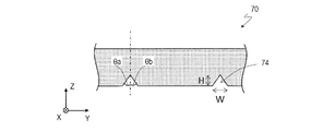
- FIG. 5 is a schematic cross-sectional view of the optical laminate 101A according to another embodiment of the present invention. It is a schematic cross-sectional view of the optical laminate 100B and the optical laminate 101B according to still another embodiment of the present invention. It is a schematic perspective view of the optical sheet 10b included in the optical laminated body 100B. It is a schematic cross-sectional view of the lighting apparatus 200 including the optical laminated body 100B. It is a schematic plan view of the shaping film 70 which the optical laminated body by embodiment of this invention has. It is a schematic cross-sectional view of the shaping film 70.
- an adhesive composition layer according to an embodiment of the present invention, a laminate having an adhesive composition layer, an adhesive layer formed from the adhesive composition layer, and an optical laminate having an adhesive layer and an optical sheet. , And a method for manufacturing an optical laminate will be described.
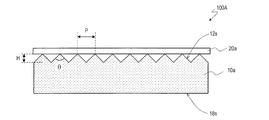
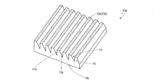
- the optical laminate 100A has an adhesive layer 20a on the uneven structure of the prism surface (first main surface) 12s of the prism sheet (first optical sheet) 10a.
- Another optical sheet for example, a microlens sheet
- the optical laminate 101A has an optical laminate 100A and a second optical sheet 30 arranged on the side opposite to the first optical sheet 10a side of the adhesive layer 20a. Since the description of the optical laminate 100A also applies to the optical laminate 101A unless otherwise specified, the description may be omitted in order to avoid duplication.
- the adhesive layer 20a is formed by curing the curable resin of the adhesive composition containing the polymer and the curable resin.
- the adhesive layer 20a is formed as follows. First, an adhesive composition layer formed from the adhesive composition is applied onto the first main surface 12s of the optical sheet 10a. Subsequently, with the adhesive composition layer applied on the first main surface 12s of the optical sheet 10a, the adhesive composition is cured by applying heat to the adhesive composition layer or irradiating it with active energy rays. Cure the sex resin.
- the adhesive composition layer to be the adhesive layer 20a is attached to the prism sheet 10a by, for example, a roll-to-roll method
- the adhesive composition layer penetrates into the concave portion of the concave-convex structure of the prism sheet 10a. It is required not to overdo it.
- the adhesive composition layer is attached to the prism sheet 10a by, for example, a roll-to-roll method
- it is required to have a certain degree of softness (easiness of deformation).
- the adhesive layer 20a is formed on the prism surface 12s of the prism sheet 10a, it is required that the degree to which the adhesive layer 20a penetrates into the recess does not change with time.
- the optical laminate 101A it is required that the deformation of the adhesive composition layer during the formation of the adhesive layer 20a and the deformation over time after the formation of the adhesive layer 20a are suppressed.
- the optical laminate 101A is, for example, after the optical laminate 100A is produced by the above method, the optical laminate 100A and the optical laminate 100A are arranged on the side opposite to the first optical sheet 10a side of the adhesive layer 20a. 2 It can be manufactured by laminating with an optical sheet 30.
- the adhesive composition layer is provided with the adhesive composition layer between the first optical sheet 10a and the second optical sheet 30 so as to be in contact with the first main surface 12s of the first optical sheet 10a.
- the optical laminate 101A may be produced by applying heat or irradiating with active energy rays to cure the curable resin of the adhesive composition to form the adhesive layer 20a.
- the laminate of the first optical sheet 10a, the adhesive composition layer and the second optical sheet 30 is a laminate in which the first optical sheet 10a and the adhesive composition layer are laminated, and the second optical sheet 30, for example. It may be formed by laminating by a roll-to-roll method, or a laminate in which the second optical sheet 30 and the adhesive composition layer are laminated and the first optical sheet 10a are, for example, roll-to-roll. It may be formed by laminating by a roll method.
- the present inventor has cured the initial tensile modulus before curing the curable resin of the adhesive composition forming the adhesive layer 20a and the curable resin of the adhesive composition forming the adhesive layer 20a. It has been found that a suitable adhesive can be selected by using the initial tensile modulus later. In the present specification, the initial tensile elastic modulus of the adhesive composition is measured as shown in the experimental examples described later.
- the degree of penetration of the adhesive layer into the recesses can be evaluated by the diffusion transmittance of the optical laminate 100A or the optical laminate 101A. The greater the degree to which the adhesive layer 20a penetrates into the recess of the prism sheet 10a, the smaller the diffusion transmittance. The diffusion transmittance of the optical laminate is measured as shown in an experimental example described later.
- the adhesive composition forming the adhesive layer 20a contained in the optical laminate 100A according to the embodiment of the present invention is 23 before the curable resin of the adhesive composition is cured.
- the initial tensile elastic modulus at ° C. is 0.35 MPa or more and 8.00 MPa or less, and the initial tensile elastic modulus at 23 ° C. after curing the curable resin of the adhesive composition is 1.00 MPa or more.
- the adhesive layer 20a is formed, that is, the adhesive composition layer is formed on the optical sheet 10a.
- the adhesive composition is prevented from entering the plurality of recesses.
- the adhesive composition layer is formed on the first main surface of the optical sheet 10a. It has the softness (easiness to deform) required to be imparted on 12s.
- the adhesive force of the adhesive composition layer to the first main surface 12s of the optical sheet 10a is sufficient. It may not be.
- the initial tensile elastic modulus at 23 ° C. after curing the curable resin of the adhesive composition is 1.00 MPa or more
- the adhesive layer 20a is formed and then the adhesive layer 20a is deformed over time. Therefore, it is suppressed from entering into a plurality of recesses. Since both the deformation of the adhesive composition layer during the formation of the adhesive layer 20a and the deformation over time after the formation of the adhesive layer 20a are suppressed, the optical laminate 100A improves the light extraction efficiency. Can be done.
- the initial tensile elastic modulus at 23 ° C. before curing the curable resin of the adhesive composition is, for example, 0.35 MPa or more, 0.40 MPa or more, 0.45 MPa or more or 0.50 MPa or more, and 8.00 MPa or less, 7.70 MPa or less, 7.50 MPa or less, 7.00 MPa or less, 6.50 MPa or less, 6.00 MPa or less, 5.50 MPa or less, 5.00 MPa or less, 4.50 MPa or less, 4.00 MPa or less, It is 3.50 MPa or less or 3.00 MPa or less.
- the upper limit of the initial tensile elastic modulus at 23 ° C. after curing the curable resin of the adhesive composition is not particularly limited, but is, for example, 1000 MPa or less, 800 MPa or less, 600 MPa or less, 400 MPa or less, or 200 MPa or less.
- the tensile elastic modulus is 3.00 MPa or more.
- the gel content of the adhesive composition before curing the curable resin is, for example, 75% or more, and the gel content after curing the curable resin of the adhesive composition is, for example, 90% or more.
- the upper limit of these gel fractions is not particularly limited, but is, for example, 100%.
- the curable resin contained in the adhesive composition examples include active energy ray (for example, visible light and ultraviolet rays) curable resin, thermosetting resin, and moisture curable resin.
- the curable resin contained in the adhesive composition contains, for example, an ultraviolet curable resin and a photopolymerization initiator, and is cured by being irradiated with light (ultraviolet rays).
- the ultraviolet curable resin preferably has, for example, a mass average molecular weight of 4000 or more from the viewpoint of suppressing the adhesive composition layer from entering the plurality of recesses.
- the polymer contained in the adhesive composition is, for example, a copolymer, which comprises at least one (meth) acrylate monomer (for example, alkyl (meth) acrylate), a hydroxyl group-containing copolymerizable monomer, and a carboxyl group-containing monomer.
- the mass ratio of the (meth) acrylate monomer to the nitrogen-containing vinyl monomer is, for example, between 95: 5 and 50:50, 95: 5.
- the polymer contained in the adhesive composition may be crosslinked.
- the polymer of the adhesive composition is crosslinked (for example, by heating) before the adhesive composition layer is applied onto the first main surface 12s of the optical sheet 10a.
- the adhesive layer 20a is formed by, for example, the following method. First, an adhesive composition solution layer is formed from an adhesive composition solution containing a polymer, a cross-linking agent, an active energy ray-curable resin, a polymerization initiator, and a solvent.
- the adhesive composition solution layer is formed, for example, on the stripped main surface of the substrate.
- the solvent of the adhesive composition solution layer is then removed and the polymer of the adhesive composition solution layer is crosslinked with a crosslinker (eg, by heating) to obtain an adhesive composition layer having a crosslinked structure. ..
- a crosslinker eg, by heating
- the adhesive composition solution layer is formed on the peeled main surface of the base material
- the adhesive composition layer is formed on the peeled main surface of the base material
- the base material and the adhesive composition are formed.
- a laminate having layers is obtained.
- the crosslinked structure formed by the polymer and the crosslinking agent is referred to as a first crosslinked structure. It is distinguished from the crosslinked structure (second crosslinked structure) formed by curing the active energy ray-curable resin, which will be described later.
- the polymer of the adhesive composition solution layer may be crosslinked in the step of removing the solvent of the adhesive composition solution layer, or after the step of removing the solvent of the adhesive composition solution layer, the adhesive composition solution. In addition to the step of removing the solvent of the layer, a step of cross-linking the polymer of the adhesive composition solution layer may be further performed. After that, the adhesive composition layer is attached onto the first main surface 12s of the optical sheet 10a, and the adhesive composition layer is placed on the first main surface 12s of the optical sheet 10a, and then the adhesive composition layer is formed.
- an adhesive layer 20a having a second crosslinked structure in addition to the first crosslinked structure is formed on the first main surface 12s of the optical sheet 10a. be able to. It is considered that the first crosslinked structure and the second crosslinked structure of the adhesive layer 20a form a so-called interpenetrating network structure (IPN).
- IPN interpenetrating network structure
- the second optical sheet 30 has a main surface 38s on the adhesive layer 20a side and a main surface 32s on the opposite side of the main surface 38s.
- the main surface 38s is a flat surface.
- Any suitable material can be adopted for the second optical sheet 30 depending on the purpose.
- the material of the second optical sheet 30 include a thermoplastic resin having light transmittance, and more specifically, for example, a (meth) acrylic resin such as polymethyl methacrylate (PMMA), or polycarbonate. Examples thereof include a film formed of a (PC) -based resin or the like.
- At least one other optical member (or optical sheet) may be arranged on the side opposite to the adhesive layer 20a of the second optical sheet 30 of the optical laminate 101A (that is, on the main surface 32s).
- the other optical member includes, for example, a diffusion plate, a light guide plate, and the like, and is adhered onto the main surface 32s of the optical sheet 30 via an adhesive layer. That is, the optical laminate of another embodiment of the present invention includes the optical laminate 101A and another optical sheet arranged on the side opposite to the adhesive layer 20a of the second optical sheet 30 of the optical laminate 101A. ..
- the optical device of another embodiment of the present invention includes an optical laminate 101A and at least one other optical member arranged on the side opposite to the adhesive layer 20a of the second optical sheet 30 of the optical laminate 101A. ..
- the 180 ° peel adhesive force of the adhesive layer 20a to the PMMA film is, for example, 10 mN / 20 mm or more.
- the upper limit is not particularly limited, but is, for example, 50N / 20mm or less, 40N / 20mm or less, 30N / 20mm or less, 20N / 20mm or less, 10N / 20mm or less, or 1N / 20mm or less.
- the haze of the adhesive layer 20a is, for example, 0.01% or more and 5% or less, 4% or less, 3% or less, 2% or less, or 1.5% or less.
- the thickness of the adhesive layer 20a is, for example, 0.1 ⁇ m or more, 0.5 ⁇ m or more or 1.0 ⁇ m or more, and 20 ⁇ m or less, 15 ⁇ m or less, 10 ⁇ m or less or 5 ⁇ m or less.
- the 180 ° peel adhesive force of the adhesive layer to the PMMA film and the haze of the adhesive layer can be measured by, for example, the methods described in the experimental examples described later.
- the adhesive forming the adhesive layer 20a the following adhesives can be preferably used as described later by showing an experimental example.
- the adhesive contains, for example, a (meth) acrylic polymer
- the (meth) acrylic polymer is, for example, a copolymer of a nitrogen-containing (meth) acrylic monomer and at least one other monomer. ..
- the nitrogen-containing (meth) acrylic monomer has, for example, a nitrogen-containing cyclic structure.
- the elastic (meth) acrylic polymer is elastic, especially when the nitrogen-containing (meth) acrylic monomer has a nitrogen-containing cyclic structure. The effect of improving the characteristics can be obtained.
- the adhesive contains a (meth) acrylic polymer
- the adhesive may further contain an active energy ray-curable resin (for example, an ultraviolet curable resin) and a curing agent (for example, a photopolymerization initiator).
- an active energy ray-curable resin for example, an ultraviolet curable resin
- a curing agent for example, a photopolymerization initiator
- a cured product of an active energy ray-curable resin may be further contained.
- the active energy rays are, for example, visible light and ultraviolet light.
- the elastic properties of the adhesive layer 20a can be improved by applying the adhesive composition layer (which becomes the adhesive layer 20a) to the optical sheet 10a and then curing the active ray-curable resin. , It is possible to suppress the change with time to the extent that the adhesive layer 20a penetrates into the recess. When the active energy ray-curable resin is cured, the adhesive layer 20a becomes hard. If the adhesive layer 20a is too hard, it may be difficult to attach the adhesive layer 20a to the optical sheet 10a by a roll-to-roll method. However, after the adhesive composition layer is applied to the optical sheet 10a. This problem can be avoided by curing the active energy ray-curable resin with.
- the adhesive preferably does not contain a graft polymer.
- the design factors and control factors of the material increase, and the mass productivity may be inferior.
- the creep properties of the adhesive containing no graft polymer can be adjusted by various factors (for example, the type and amount of the cross-linking agent, the type and amount of the active ray-curable resin).
- the adhesive contains, for example, a (meth) acrylic polymer.
- Any (meth) acrylate can be used as the monomer used in the production of the (meth) acrylic polymer, and the monomer is not particularly limited.
- an alkyl (meth) acrylate having an alkyl group having 4 or more carbon atoms can be used.
- the ratio of the alkyl (meth) acrylate having an alkyl group having 4 or more carbon atoms to the total amount of the monomers used in the production of the (meth) acrylic polymer is, for example, 50% by mass or more.
- alkyl (meth) acrylate refers to (meth) acrylate having a linear or branched alkyl group.
- the alkyl group of the alkyl (meth) acrylate preferably has 4 or more carbon atoms, and more preferably 4 or more and 9 or less carbon atoms.
- (meth) acrylate means acrylate and / or methacrylate.
- alkyl (meth) acrylates include n-butyl (meth) acrylate, s-butyl (meth) acrylate, t-butyl (meth) acrylate, isobutyl (meth) acrylate, n-pentyl (meth) acrylate, and isopentyl.
- the adhesive may contain a (meth) acrylic polymer, which is a copolymer of a nitrogen-containing (meth) acrylic monomer and at least one other monomer.
- the (meth) acrylic polymer is a copolymer obtained by copolymerizing the following monomers in the following amounts when the total amount of the monomers used for the copolymerization is 100 parts by mass. Is preferable.
- Nitrogen-containing (meth) acrylic monomer 10.0 parts by mass or more, 15.0 parts by mass or more, 20.0 parts by mass or more, 25.0 parts by mass or more, 30.0 parts by mass or more or 35.0 parts by mass or more Yes, and 40.0 parts by mass or less, 35.0 parts by mass or less, 30.0 parts by mass or less, 25.0 parts by mass or less, 20.0 parts by mass or less, or 15.0 parts by mass or less.
- Hydroxyl group-containing acrylic monomer 0.05 parts by mass or more, 0.75 parts by mass or more, 1.0 parts by mass or more, 2.0 parts by mass or more, 3.0 parts by mass or more, 4.0 parts by mass or more, 5.
- 0 parts by mass or more 6.0 parts by mass or more, 7.0 parts by mass or more, 8.0 parts by mass or more or 9.0 parts by mass or more, and 10.0 parts by mass or less, 9.0 parts by mass or less , 8.0 parts by mass or less, 7.0 parts by mass or less, 6.0 parts by mass or less, 5.0 parts by mass or less, 4.0 parts by mass or less, 3.0 parts by mass or less, 2.0 parts by mass or less or 1.0 part by mass or less.
- Carboxyl group-containing acrylic monomer 1.0 part by mass or more, 2.0 part by mass or more, 3.0 part by mass or more, 4.0 part by mass or more, 5.0 part by mass or more, 6.0 part by mass or more, 7. 0 parts by mass or more, 8.0 parts by mass or more or 9.0 parts by mass or more, and 10.0 parts by mass or less, 9.0 parts by mass or less, 8.0 parts by mass or less, 7.0 parts by mass or less , 6.0 parts by mass or less, 5.0 parts by mass or less, 4.0 parts by mass or less, 3.0 parts by mass or less or 2.0 parts by mass or less.
- Alkyl (meth) acrylate monomer (100 parts by mass)-(total amount of monomers other than alkyl (meth) acrylate monomer used for copolymerization)
- the "nitrogen-containing (meth) acrylic monomer” includes a monomer having a polymerizable functional group having an unsaturated double bond of a (meth) acryloyl group and having a nitrogen atom without particular limitation.
- the "nitrogen-containing (meth) acrylic monomer” has, for example, a nitrogen-containing cyclic structure.
- nitrogen-containing cyclic structures include N-vinyl-2-pyrrolidone (NVP), N-vinyl- ⁇ -caprolactam (NVC), and 4-acryloyl morpholine (ACMO). These can be used alone or in combination.
- the "hydroxyl group-containing acrylic monomer” includes a monomer having a polymerizable functional group having an unsaturated double bond of a (meth) acryloyl group and having a hydroxyl group without particular limitation.
- the "carboxyl group-containing acrylic monomer” is not particularly limited to a monomer having a polymerizable functional group having an unsaturated double bond such as a (meth) acryloyl group or a vinyl group and having a carboxyl group.
- examples of the unsaturated carboxylic acid-containing monomer include (meth) acrylic acid, carboxyethyl (meth) acrylate, carboxypentyl (meth) acrylate, itaconic acid, maleic acid, fumaric acid, and crotonic acid. These can be used alone or in combination.
- the adhesive may contain a (meth) acrylic polymer which is a copolymer of a carboxyl group-containing acrylic monomer and at least one other monomer (excluding nitrogen-containing (meth) acrylic monomer).
- the (meth) acrylic polymer is a copolymer obtained by copolymerizing the following monomers in the following amounts when the total amount of the monomers used for the copolymerization is 100 parts by mass. Is preferable.
- Carboxyl group-containing acrylic monomer 1.0 part by mass or more, 2.0 part by mass or more, 3.0 part by mass or more, 4.0 part by mass or more, 5.0 part by mass or more, 6.0 part by mass or more, 7.
- 0 parts by mass or more 8.0 parts by mass or more or 9.0 parts by mass or more, and 10.0 parts by mass or less, 9.0 parts by mass or less, 8.0 parts by mass or less, 7.0 parts by mass or less , 6.0 parts by mass or less, 5.0 parts by mass or less, 4.0 parts by mass or less, 3.0 parts by mass or less or 2.0 parts by mass or less.
- Alkyl (meth) acrylate monomer 90.0 parts by mass or more, 91.0 parts by mass or more, 92.0 parts by mass or more, 93.0 parts by mass or more, 94.0 parts by mass or more, 95.0 parts by mass or more, 96 9.0 parts by mass or more, 97.0 parts by mass or more or 98.0 parts by mass or more, 99.0 parts by mass or less, 98.0 parts by mass or less, 97.0 parts by mass or less, 96.0 parts by mass or less , 95.0 parts by mass or less, 94.0 parts by mass or less, 93.0 parts by mass or less, 92.0 parts by mass or less or 91.0 parts by mass or less.
- cross-linking agent for introducing a cross-linked structure into the (meth) acrylic polymer examples include an isocyanate-based cross-linking agent, an epoxy-based cross-linking agent, a silicone-based cross-linking agent, an oxazoline-based cross-linking agent, an aziridine-based cross-linking agent, a silane-based cross-linking agent, and an alkyl ether.
- cross-linking agents such as melamine-based cross-linking agents, metal chelate-based cross-linking agents, and peroxides.
- the cross-linking agent may be used alone or in combination of two or more.
- the isocyanate-based cross-linking agent refers to a compound having two or more isocyanate groups (including an isocyanate regenerated functional group in which the isocyanate group is temporarily protected by a blocking agent or quantification) in one molecule.
- isocyanate-based cross-linking agent examples include aromatic isocyanates such as tolylene diisocyanate and xylene diisocyanate, aliphatic isocyanates such as isophorone diisocyanate, and aliphatic isocyanates such as hexamethylene diisocyanate.
- lower aliphatic polyisocyanates such as butylene diisocyanate and hexamethylene diisocyanate
- alicyclic isocyanates such as cyclopentylene diisocyanate, cyclohexylene diisocyanate and isophorone diisocyanate
- 2,4-tolylene diisocyanate Aromatic diisocyanates such as 4,4'-diphenylmethane diisocyanate, xylylene diisocyanate, polymethylene polyphenyl isocyanate, trimethylolpropane / tolylene diisocyanate trimer adduct (manufactured by Toso Co., Ltd., trade name Coronate L), trimethylol Isocyanate adducts such as propane / hexamethylene diisocyanate trimeric adduct (manufactured by Toso Co., Ltd., trade name Coronate HL), isocyanurates of
- the blending amount of the isocyanate-based cross-linking agent is, for example, 0.01 part by mass or more, 0.02 part by mass or more, 0.05 part by mass or more, or 0.1 part by mass or more with respect to 100 parts by mass of the (meth) acrylic polymer. And 10 parts by mass or less, 9 parts by mass or less, 8 parts by mass or less, 7 parts by mass or less, 6 parts by mass or less or 5 parts by mass or less, preferably 0.01 parts by mass or more and 10 parts by mass or less. , 0.02 parts by mass or more and 9 parts by mass or less, or 0.05 parts by mass or more and 8 parts by mass or less.
- the blending amount may be appropriately adjusted in consideration of cohesive force, prevention of peeling in the durability test, and the like.
- aqueous dispersion of the modified (meth) acrylic polymer prepared by emulsion polymerization it is not necessary to use an isocyanate-based cross-linking agent, but if necessary, it is blocked because it easily reacts with water. It is also possible to use the above-mentioned isocyanate-based cross-linking agent.
- the epoxy-based cross-linking agent is a polyfunctional epoxy compound having two or more epoxy groups in one molecule.
- the epoxy-based cross-linking agent include bisphenol A, epichlorohydrin-type epoxy resin, ethylene glycidyl ether, N, N, N', N'-tetraglycidyl-m-xylene diamine, diglycidyl aniline, diamine glycidyl amine, 1 , 3-Bis (N, N-diglycidylaminomethyl) cyclohexane, 1,6-hexanediol diglycidyl ether, neopentyl glycol diglycidyl ether, ethylene glycol diglycidyl ether, propylene glycol diglycidyl ether, polyethylene glycol diglycidyl ether , Polypropylene glycol diglycidyl ether, sorbitol polyglycidyl ether, glycerol polyglycidyl ether,
- the blending amount of the epoxy-based cross-linking agent is, for example, 0.01 part by mass or more, 0.02 part by mass or more, 0.05 part by mass or more, or 0.1 part by mass or more with respect to 100 parts by mass of the (meth) acrylic polymer. And 10 parts by mass or less, 9 parts by mass or less, 8 parts by mass or less, 7 parts by mass or less, 6 parts by mass or less or 5 parts by mass or less, preferably 0.01 parts by mass or more and 10 parts by mass or less. , 0.02 parts by mass or more and 9 parts by mass or less, or 0.05 parts by mass or more and 8 parts by mass or less.
- the blending amount may be appropriately adjusted in consideration of cohesive force, prevention of peeling in the durability test, and the like.
- the peroxide cross-linking agent can be appropriately used as long as it generates radically active species by heating to promote cross-linking of the base polymer of the pressure-sensitive adhesive, but in consideration of workability and stability, it can be used as appropriate. It is preferable to use a peroxide having a one-minute half-life temperature of 80 ° C. or higher and 160 ° C. or lower, and more preferably 90 ° C. or higher and 140 ° C. or lower.
- peroxide examples include di (2-ethylhexyl) peroxydicarbonate (1 minute half-life temperature: 90.6 ° C.) and di (4-t-butylcyclohexyl) peroxydicarbonate (1 minute half-life temperature).
- the half-life of peroxide is an index showing the decomposition rate of peroxide, and means the time until the residual amount of peroxide is halved.
- the decomposition temperature for obtaining a half-life at an arbitrary temperature and the half-life time at an arbitrary temperature are described in the manufacturer's catalog, etc. For example, "Organic peroxide catalog 9th edition" of Nichiyu Co., Ltd. (May 2003) ”and so on.
- One type of peroxide may be used alone, or two or more types may be mixed and used.
- the blending amount of the peroxide is 0.02 parts by mass or more and 2 parts by mass or less, and preferably 0.05 parts by mass or more and 1 part by mass or less with respect to 100 parts by mass of the (meth) acrylic polymer. It is appropriately adjusted within this range in order to adjust workability, reworkability, cross-linking stability, peelability and the like.
- HPLC high performance liquid chromatography
- an organic cross-linking agent or a polyfunctional metal chelate may be used in combination.
- a polyfunctional metal chelate is one in which a polyvalent metal is covalently or coordinated to an organic compound.
- the polyvalent metal atom include Al, Cr, Zr, Co, Cu, Fe, Ni, V, Zn, In, Ca, Mg, Mn, Y, Ce, Sr, Ba, Mo, La, Sn, Ti and the like.
- Examples of the atom in the organic compound having a covalent bond or a coordination bond include an oxygen atom
- examples of the organic compound include an alkyl ester, an alcohol compound, a carboxylic acid compound, an ether compound, and a ketone compound.
- the blending amount of the active energy ray-curable resin is, for example, 3 parts by mass or more and 60 parts by mass or less with respect to 100 parts by mass of the (meth) acrylic polymer.
- the mass average molecular weight (Mw) before curing is 4000 or more and 50,000 or less.
- an acrylate-based, epoxy-based, urethane-based, or en-thiol-based ultraviolet curable resin can be preferably used.
- the active energy ray-curable resin a monomer and / or an oligomer that is radically polymerized or cationically polymerized by the active energy ray is used.
- Examples of the monomer radically polymerized by the active energy ray include a monomer having an unsaturated double bond such as a (meth) acryloyl group and a vinyl group, and a monomer having a (meth) acryloyl group is preferably used because of its excellent reactivity. Be done.
- the monomer having a (meth) acryloyl group examples include allyl (meth) acrylate, caprolactone (meth) acrylate, cyclohexyl (meth) acrylate, N, N-diethylaminoethyl (meth) acrylate, and 2-ethylhexyl.
- Polyester (meth) acrylate is obtained by reacting (meth) acrylic acid with polyester having a terminal hydroxyl group obtained from a polyhydric alcohol and a polyvalent carboxylic acid. 6000, 7000, 8000, 9000 series and the like can be mentioned.
- Epoxy (meth) acrylate is obtained by reacting epoxy resin with (meth) acrylic acid, and specific examples include Lipoxy SP and VR series manufactured by Showa High Polymer Co., Ltd. and epoxy esters manufactured by Kyoeisha Chemical Co., Ltd. Series etc. can be mentioned.
- Urethane (meth) acrylate is obtained by reacting polyol, isocyanate, and hydroxy (meth) acrylate.
- Specific examples include Art Resin UN series manufactured by Negami Kogyo Co., Ltd. and NK manufactured by Shin Nakamura Chemical Industry Co., Ltd. Examples thereof include the oligo U series and the purple light UV series manufactured by Mitsubishi Chemical Industry Co., Ltd.
- the photopolymerization initiator has the effect of exciting and activating by irradiating with ultraviolet rays to generate radicals, and curing the polyfunctional oligomer by radical polymerization.
- photopolymerization initiators such as beron, 2-ethylanthraquinone, 4', 4 "-diethylisophthalofenone and the like can be mentioned.
- the photopolymerization initiator include allylsulfonium hexafluorophosphate salt and sulfonium hexafluoro.
- Phosphate salts and photocationic polymerization initiators such as bis (alkylphenyl) iodonium hexafluorophosphate can also be used.
- the polymerization initiator is usually preferably added in a range of 0.5 parts by mass or more and 30 parts by mass or less, and further 1 part by mass or more and 20 parts by mass or less with respect to 100 parts by mass of the active energy ray-curable resin. If it is less than 0.5 parts by mass, the polymerization does not proceed sufficiently, the curing rate becomes slow, and if it exceeds 30 parts by mass, the hardness of the cured sheet may decrease.
- the active energy ray is not particularly limited, but is preferably ultraviolet light, visible light, electron beam, or the like.
- the cross-linking treatment by ultraviolet irradiation can be performed using an appropriate ultraviolet source such as a high-pressure mercury lamp, a low-pressure mercury lamp, an excimer laser, a metal halide lamp, or an LED lamp.
- the irradiation amount of ultraviolet rays can be appropriately selected according to the required degree of cross-linking, but usually, for ultraviolet rays, it is selected within the range of 0.2 J / cm 2 or more and 10 J / cm 2 or less. It is desirable to do.
- the temperature at the time of irradiation is not particularly limited, but is preferably up to about 140 ° C. in consideration of the heat resistance of the support.
- optical laminates 100B and 101B according to other embodiments of the present invention will be described with reference to FIGS. 3 to 5.
- the optical laminate 100B functions as a light distribution control element described in Patent Document 2, and can be manufactured by using a roll-to-roll method.
- Patent Document 2 all the disclosure contents of Patent Document 2 are incorporated herein by reference.
- FIG. 3 is a schematic cross-sectional view of the optical laminates 100B and 101B, showing a state in which the first optical sheet 10b is adhered to the surface 38s of the second optical sheet 30 via the adhesive layer 20b.
- FIG. 4 is a schematic perspective view of the first optical sheet 10b included in the optical laminate 100B.
- FIG. 5 is a schematic cross-sectional view of an illuminating device 200 including an optical laminate 102B and a light source 60, and schematically shows a trajectory of light rays.
- the optical laminate 100B is arranged on the first main surface 12s having a concavo-convex structure, the optical sheet 10b having the second main surface 18s opposite to the first main surface 12s, and the first main surface 12s side of the optical sheet 10b. It has an adhesive layer 20b and the like.
- the optical laminate 101B has an optical laminate 100B and a second optical sheet 30 arranged on the side opposite to the first optical sheet 10b side of the adhesive layer 20a.
- the uneven structure of the first main surface 12s of the optical sheet 10b includes a plurality of recesses 14, and the surface of the adhesive layer 20b and the first main surface 12s of the optical sheet 10b are present in the plurality of recesses 14. Space 14 (indicated by the same reference code as the recess) is defined.
- the adhesive layer 20b is an essential component for defining the space 14 of the optical laminate 100B, and is a part of the optical laminate 100B.
- the uneven structure of the optical sheet 10b includes a flat portion 10s in contact with the adhesive layer 20b.
- the concave-convex structure includes, for example, a plurality of convex portions 15 having a trapezoidal cross section. Since the concavo-convex structure has a flat portion 10s in contact with the adhesive layer 20b, the concavo-convex structure of the optical sheet 10b has an adhesive layer in the recesses rather than the concavo-convex structure of the prism surface of the prism sheet 10a shown in FIG. 20b is hard to invade. Therefore, by using the above-mentioned adhesive, it is possible to obtain an optical laminate 100B in which the adhesive layer 20b does not invade a plurality of spaces 14 and does not change with time.
- the optical sheet 10b can be manufactured by the same method using the same material as the known prism sheet or microlens sheet.
- the size and shape of the concave-convex structure of the optical sheet 10b can be changed as appropriate (Patent Document 2).
- Patent Document 2 the optical sheet 10b is different from the known prism sheet or microlens sheet in that the optical sheet 10b functions as the optical laminate 100B in which the space 14 is defined only when it is adhered to the adhesive layer 20b.
- the second optical sheet 30 is arranged so as to adhere to the surface 22s of the adhesive layer 20b on its surface 38s.
- any suitable material can be adopted depending on the purpose.
- the material of the second optical sheet 30 include a light-transmitting thermoplastic resin, and more specifically, for example, a (meth) acrylic resin such as polymethyl methacrylate (PMMA) and polycarbonate (PC). ) A film formed of a resin can be mentioned.
- the space 14 of the optical laminate 100B is defined by a surface 16s and a surface 17s that are a part of the first main surface 12s of the optical sheet 10b, and a surface 28s of the adhesive layer 20b.
- a surface 16s and a surface 17s that are a part of the first main surface 12s of the optical sheet 10b, and a surface 28s of the adhesive layer 20b.
- the surface 16s is inclined (more than 0 ° and less than 90 °) with respect to the sheet surface (horizontal direction in the figure), and the surface 17s is substantially perpendicular to the sheet surface. It is not limited and can be modified in various ways (see Patent Document 2).
- the optical laminate 100B is used in the lighting device 200, for example, as shown in FIG.
- a light guide plate 50 is provided on the side of the adhesive layer 20b of the optical laminate 100B opposite to the first optical sheet 10b side.
- the optical laminate 100B and the light guide plate 50 are collectively referred to as an optical laminate 102B.
- the optical laminate 102B is adhered to the light guide plate 50 on the surface 22s of the adhesive layer 20b of the optical laminate 100B.
- the light receiving surface of the light guide plate 50 is arranged so that the light from the light source (for example, LED) 60 is incident, and the light rays guided into the light guide plate 50 are as shown by arrows in FIG.
- Total internal reflection (TIR) is performed at the interface 16s and the interface 14s created by the space 14.
- the light rays totally reflected at the interface 14s (the surface 28s of the adhesive layer 20b) guide the inside of the light guide plate 50 and the adhesive layer 20b, and the light rays totally reflected at the slope 16s are the surfaces 18s of the optical laminate 100B. Is emitted to the outside.
- the distribution (light distribution) of the light rays emitted from the optical laminate 100B can be adjusted.
- the light guide plate 50, the adhesive layer 20b, and the optical sheet 10b have the same refractive index.
- FIGS. 3 to 5 show an example in which the cross-sectional shape of the convex portion 15 is trapezoidal
- the shape of the convex portion 15 is not limited to that shown and can be modified in various ways.
- the shape, size, and the like of the convex portion 15 can be adjusted.
- International Publication No. 2011/124765 describes an example of a laminate having a plurality of spaces inside.
- all disclosures of WO 2011/124765 are incorporated herein by reference.
- Example 1 (Preparation of adhesive composition solution) First, an acrylic polymer was prepared. A four-necked flask equipped with a stirring blade, a thermometer, a nitrogen gas introduction tube, and a cooler contains 62.9 parts by mass of n-butyl acrylate (BA), 33.9 parts by mass of 4-acryloyl morpholine (ACMO), and acrylic acid. (AA) 2.9 parts by mass, 4-hydroxybutyl acrylate (4HBA) 0.3 parts by mass, and 2,2'-azobisisobutyronitrile 0.1 parts by mass as a polymerization initiator, for a total of 50 parts by mass of monomers.
- BA n-butyl acrylate
- ACMO 4-acryloyl morpholine
- AA 2.9 parts by mass
- 4-hydroxybutyl acrylate (4HBA) 0.3 parts by mass
- 2,2'-azobisisobutyronitrile 0.1 parts by mass as a polymerization initiator
- Acrylic acid was charged into a flask together with ethyl acetate so as to be%, nitrogen gas was introduced while gently stirring, and the mixture was replaced with nitrogen for 1 hour.
- a system polymer was obtained.
- ethyl acetate was added dropwise over 3 hours so that the solid content became 35% by mass. That is, the acrylic polymer was obtained as an acrylic polymer solution having a solid content of 35% by mass.
- An adhesive composition solution was applied to one side of a 38 ⁇ m-thick polyethylene terephthalate (PET) film (trade name “MRF38”, manufactured by Mitsubishi Chemical Corporation) that had been subjected to silicone peeling treatment to form an adhesive composition solution layer.
- PET polyethylene terephthalate
- MRF38 polyethylene terephthalate
- the thickness of the adhesive composition solution layer was applied so that the thickness after drying (that is, the thickness of the adhesive composition layer) was 1 ⁇ m.
- the solvent of the adhesive composition solution layer is removed and the acrylic polymer is crosslinked with a cross-linking agent to form an adhesive composition having a first cross-linked structure. Got a layer.
- PET polyethylene terephthalate
- the second laminated body is irradiated with ultraviolet rays from the upper surface (acrylic resin film side) of the second laminated body to cure the curable resin of the adhesive composition layer, thereby first cross-linking.
- the optical laminate (third laminate) of Example 1 having a laminated structure of an acrylic resin film / adhesive layer / prism sheet (optical sheet) by forming an adhesive layer having a second crosslinked structure in addition to the structure. ) was obtained.
- an LED lamp manufactured by Quark Technology Co., Ltd., peak illuminance: 200 mW / cm 2 , integrated light intensity 1500 mJ / cm 2 (wavelength 345 to 365 nm)
- the ultraviolet illuminance is UV Power Pack (Fusion UV Systems. Measured using (manufactured by Japan Co., Ltd.).
- Example 2 in the preparation of the adhesive composition solution, the acrylic polymer solution prepared in the same manner as in Example 1 was prepared as an ultraviolet curable urethane acrylate with respect to 100 parts by mass of the polymer as an ultraviolet curable resin.
- Example 3 In Example 3, in the preparation of the adhesive composition solution, an ultraviolet curable urethane acrylate was used as an ultraviolet curable resin with respect to 100 parts by mass of the polymer in the acrylic polymer solution prepared in the same manner as in Example 1. 5 parts by mass of resin A in solid content, 0.5 parts by mass of 2,2-dimethoxy-1,2-diphenylethane-1-one (trade name "Omnirad 651", manufactured by IGM Japan LLC) as a photopolymerization initiator, It differs from Example 1 in that 0.1 part by mass of 1,3-bis (N, N-diglycidylaminomethyl) cyclohexane (trade name "TETRAD-C", manufactured by Mitsubishi Gas Chemicals Corporation) was blended as a cross-linking agent. .. Others were the same as in Example 1.
- Example 4 in the preparation of the adhesive composition solution, an ultraviolet curable urethane acrylate was used as an ultraviolet curable resin with respect to 100 parts by mass of the polymer in the acrylic polymer solution prepared in the same manner as in Example 1.
- 9 parts by mass of resin A in solid content 0.9 parts by mass of 2,2-dimethoxy-1,2-diphenylethane-1-one (trade name "Omnirad 651", manufactured by IGM Japan LLC) as a photopolymerization initiator, It differs from Example 1 in that 0.1 part by mass of 1,3-bis (N, N-diglycidylaminomethyl) cyclohexane (trade name "TETRAD-C", manufactured by Mitsubishi Gas Chemicals Corporation) was blended as a cross-linking agent. .. Others were the same as in Example 1.
- Example 5 In Example 5, in the preparation of the acrylic polymer, n-butyl acrylate, 4-acryloyl morpholine, acrylic acid, and 4-hydroxybutyl acrylate were added to 58.1 parts by mass / 38.7 parts by mass / 2.9, respectively. It differs from Example 1 in that it is made by mass part / 0.3 part by mass. Further, in the preparation of the adhesive composition solution, 5 parts by mass of the ultraviolet curable urethane acrylate resin A as the ultraviolet curable resin was added to the obtained acrylic polymer solution as an ultraviolet curable resin with respect to 100 parts by mass of the polymer.
- Example 1 2,2-Dimethoxy-1,2-diphenylethane-1-one (trade name "Omnirad651", manufactured by IGM Japan LLC) as a photopolymerization initiator, 0.5 parts by mass, and 1,3-bis (trade name) as a cross-linking agent. It differs from Example 1 in that 0.1 parts by mass of N, N-diglycidylaminomethyl) cyclohexane (trade name “TETRAD-C”, manufactured by Mitsubishi Gas Chemicals Corporation) was blended. Others were the same as in Example 1.
- Example 6 In Example 6, in the preparation of the acrylic polymer, n-butyl acrylate, 4-acryloyl morpholine, acrylic acid, and 4-hydroxybutyl acrylate were added to 67.8 parts by mass / 29.0 parts by mass / 2.9, respectively. It differs from Example 1 in that it is made by mass part / 0.3 part by mass. Further, in the preparation of the adhesive composition solution, an ultraviolet curable urethane acrylate resin (trade name "Shikou UV-7610B”) was added to the obtained acrylic polymer solution as an ultraviolet curable resin with respect to 100 parts by mass of the polymer.
- an ultraviolet curable urethane acrylate resin trade name "Shikou UV-7610B”
- Example 1 Mitsubishi Chemical Co., Ltd., mass average molecular weight Mw: 11,000 in 30 parts by mass in solid content, 2,2-dimethoxy-1,2-diphenylethane-1-one as a photopolymerization initiator (trade name " Polymer 651 ", manufactured by IGM Japan LLC) 3.0 parts by mass, 1,3-bis (N, N-diglycidylaminomethyl) cyclohexane as a cross-linking agent (trade name” TETRAD-C ", manufactured by Mitsubishi Gas Chemicals, Ltd.) It differs from Example 1 in that 0.1 parts by mass is blended. Others were the same as in Example 1.
- Example 7 (Preparation of adhesive composition solution)
- n-butyl acrylate, 4-acryloyl morpholine, acrylic acid, and 4-hydroxybutyl acrylate were added to 74.6 parts by mass / 18.6 parts by mass / 6.5, respectively. It differs from Example 1 in that it is made by mass part / 0.3 part by mass.
- the obtained acrylic polymer solution contains 10 parts by mass of an ultraviolet curable urethane acrylate resin A as an ultraviolet curable resin with respect to 100 parts by mass of the polymer.
- Example 1 4- (2-Hydroxyethoxy) phenyl (2-hydroxy-2-propyl) ketone (trade name "Omnirad2959", manufactured by IGM Japan GK) as a photopolymerization initiator, 1.0 part by mass, and 1, as a cross-linking agent. It differs from Example 1 in that 0.6 parts by mass of 3-bis (N, N-diglycidylaminomethyl) cyclohexane (trade name "TETRAD-C", manufactured by Mitsubishi Gas Chemicals Corporation) was blended. Others were the same as in Example 1.
- Example 7a having a laminated structure of an acrylic resin film / adhesive layer / optical sheet (unevenness shaping film) in the same manner as in Example 7 except that the following unevenness shaping film 70 is used as the optical sheet.
- the optical laminate of No. 1 was produced.
- FIG. 6A shows a plan view of a part of the manufactured uneven shape shaping film 70 as viewed from the uneven surface side.
- FIG. 6B a cross-sectional view of 6B-6B'of the uneven shaping film of FIG. 6A is shown in FIG. 6B.
- a plurality of recesses 74 having a length L of 80 ⁇ m, a width W of 14 ⁇ m, and a depth H of 10 ⁇ m and having a triangular cross section were arranged at intervals of a width E (155 ⁇ m) in the X-axis direction. Further, the patterns of such recesses 74 are arranged at intervals of a width D (100 ⁇ m) in the Y-axis direction.
- the density of the recesses 74 on the surface of the uneven shaping film was 3612 pieces / cm 2 . Both ⁇ a and ⁇ b in FIG. 6B were 41 °, and the occupied area ratio of the recess 74 when the film was viewed in a plan view from the uneven surface side was 4.05%.
- Example 8 in the production of the adhesive sheet (first laminated body), the thickness of the adhesive composition solution layer is set to 10 ⁇ m after drying (that is, the thickness of the adhesive composition layer). In that respect, it differs from Example 7. Others were the same as in Example 7.
- Example 8a The optics of Example 8a having a laminated structure of an acrylic resin film / adhesive layer / optical sheet (concavo-convex shaping film) in the same manner as in Example 8 except that the uneven shaping film 70 was used as the optical sheet. A laminate was produced.
- Comparative Example 1 (Preparation of adhesive composition solution)
- n-butyl acrylate, 4-acryloyl morpholine, acrylic acid and 4-hydroxybutyl acrylate were added in an amount of 53.2 parts by mass / 43.6 parts by mass / 2.9 parts by mass, respectively. It differs from Example 1 in that the portion is 0.3 parts by mass.
- the obtained acrylic polymer solution is different from Example 1 in that an adhesive composition solution is prepared by blending only a cross-linking agent without blending an ultraviolet curable resin and a photopolymerization initiator. ..
- An adhesive composition solution was applied to one side of a 38 ⁇ m-thick polyethylene terephthalate (PET) film (trade name “MRF38”, manufactured by Mitsubishi Chemical Corporation) that had been subjected to silicone peeling treatment to form an adhesive composition solution layer.
- PET polyethylene terephthalate
- MRF38 polyethylene terephthalate
- the thickness of the adhesive composition solution layer was applied so that the thickness after drying (that is, the thickness of the adhesive layer) was 1 ⁇ m.
- the solvent of the adhesive composition solution layer is removed by drying the adhesive composition solution layer at 150 ° C. for 3 minutes, and the acrylic polymer is crosslinked with a cross-linking agent to obtain an adhesive layer having a crosslinked structure. Obtained.
- the adhesive composition solution contains an acrylic polymer, a cross-linking agent, an ultraviolet curable resin, a photopolymerization initiator, and a solvent.
- the adhesive composition solution layer formed from the adhesive composition solution is dried at 150 ° C. for 3 minutes, and the acrylic polymer is crosslinked with a crosslinking agent to have an adhesive composition having a first crosslinked structure.
- a material layer was formed, and then the ultraviolet curable resin of the adhesive composition layer was cured to form an adhesive layer having a second crosslinked structure in addition to the first crosslinked structure.
- the adhesive composition solution does not contain an ultraviolet curable resin and a photopolymerization initiator.
- the adhesive composition solution layer formed from the adhesive composition solution was dried at 150 ° C. for 3 minutes, and the acrylic polymer was crosslinked with a crosslinker to form an adhesive layer having a crosslinked structure. Will be done.
- PET film polyethylene terephthalate (PET) film (trade name "MRE38", manufactured by Mitsubishi Chemical Co., Ltd.) having a thickness of 38 ⁇ m that has been subjected to the silicone peeling treatment is bonded to the adhesive layer, and the PET film / adhesive layer / PET An adhesive sheet (first laminated body) having a laminated structure of films was produced.
- PET polyethylene terephthalate
- PET film is peeled off and attached to the prism surface of a prism sheet (manufactured by Nippon Special Optical Resin Co., Ltd., product number "LPV90-0.01S") with irregularities with a pitch of 10 ⁇ m and a height of 5.0 ⁇ m.
- a laminated body (second laminated body) having a laminated structure of a based resin film / adhesive layer / prism sheet (optical sheet) was obtained. This second laminated body was used as the optical laminated body of Comparative Example 1.
- Comparative Example 2 In Comparative Example 2, in the preparation of the acrylic polymer, n-butyl acrylate, 4-acryloyl morpholine, acrylic acid, and 4-hydroxybutyl acrylate were added to 58.1 parts by mass / 38.7 parts by mass / 2.9, respectively. It differs from Comparative Example 1 in that it is made by mass part / 0.3 part by mass. Others were the same as in Comparative Example 1.
- Comparative Example 3 In Comparative Example 3, in the preparation of the acrylic polymer, n-butyl acrylate, 4-acryloyl morpholine, acrylic acid, and 4-hydroxybutyl acrylate were added to 67.8 parts by mass / 29.0 parts by mass / 2.9, respectively. It differs from Example 1 in that it is made by mass part / 0.3 part by mass. Further, in the preparation of the adhesive composition solution, an ultraviolet curable urethane acrylate resin (trade name "Shikou UV-1700B”) was added to the obtained acrylic polymer solution as an ultraviolet curable resin with respect to 100 parts by mass of the polymer.
- an ultraviolet curable urethane acrylate resin trade name "Shikou UV-1700B
- Example 1 Mitsubishi Chemical Co., Ltd., mass average molecular weight Mw: 2,000
- 2,2-dimethoxy-1,2-diphenylethane-1-one as a photopolymerization initiator
- Polymer 651 manufactured by IGM Japan LLC
- 1,3-bis (N, N-diglycidylaminomethyl) cyclohexane as a cross-linking agent
- TETRAD-C manufactured by Mitsubishi Gas Chemicals, Ltd.
- Comparative Example 4 In Comparative Example 4, in the preparation of the acrylic polymer, n-butyl acrylate, 4-acryloyl morpholine, acrylic acid, and 4-hydroxybutyl acrylate were added to 77.4 parts by mass / 19.4 parts by mass / 2.9, respectively. It differs from Comparative Example 1 in that it is made by mass part / 0.3 part by mass. Others were the same as in Comparative Example 1.
- Comparative Example 5 In Comparative Example 5, in the preparation of the acrylic polymer, n-butyl acrylate, 4-acryloyl morpholine, acrylic acid, and 4-hydroxybutyl acrylate were added to 92.0 parts by mass / 4.8 parts by mass / 2.9, respectively. It differs from Comparative Example 1 in that it is made by mass part / 0.3 part by mass. Others were the same as in Comparative Example 1.
- the adhesive sheet (first laminated body) before curing the curable resin was irradiated with ultraviolet rays to irradiate the ultraviolet curable resin of the adhesive composition layer.
- sample Sample B the gel fraction after curing the curable resin of the adhesive composition was also evaluated by the same method as above.
- rice field For ultraviolet irradiation, an LED lamp (manufactured by Quark Technology Co., Ltd., peak illuminance: 200 mW / cm 2 , integrated light intensity 1500 mJ / cm 2 (wavelength 345 to 365 nm)) is used, and the ultraviolet illuminance is UV Power Pack (Fusion UV Systems. Measured using (manufactured by Japan Co., Ltd.).
- the PET film / adhesive composition layer is the same as the above-mentioned adhesive sheet (first laminated body), except that the thickness of the adhesive composition layer is 10 ⁇ m.
- An adhesive sheet (fifth laminated body) having a laminated structure of (thickness 10 ⁇ m) / PET film was produced.
- a sample piece having a width of 30 mm and a length of 60 mm is cut out from the adhesive sheet (fifth laminated body), one of the peeled PET films is peeled off, and the exposed adhesive composition layer has a cross-sectional area of about 0.
- a sample for measurement was prepared by rolling it into a cylinder of .6 mm 2.
- the thickness of the adhesive layer is 10 ⁇ m, and the PET film / adhesive layer (thickness 10 ⁇ m).
- An adhesive sheet (sixth laminated body) having a laminated structure of PET film was produced.
- a sample piece having a width of 30 mm and a length of 60 mm was cut out from the adhesive sheet (sixth laminated body), one of the peeled PET films was peeled off, and the exposed adhesive layer had a cross-sectional area of about 0.6 mm.
- a sample for measurement was prepared by rolling it into a cylindrical shape of 2.
- the above cylindrical measurement sample was set in a tensile compression tester (device name "AGS-50NX", manufactured by Shimadzu Corporation), a chuck distance of 10 mm, and a tensile speed.
- the amount of change (mm) due to the axial extension of the cylinder under the condition of 50 mm / min was measured.
- Examples 1 to 8 and Comparative Example 3 were similarly evaluated using an adhesive sheet having an adhesive composition layer after the curable resin was cured, and the curable resin was irradiated with ultraviolet rays to obtain the curable resin.
- the initial tensile modulus of the adhesive composition after curing (that is, the initial tensile modulus of the adhesive layer) was also evaluated.
- the fifth laminated body is irradiated with ultraviolet rays to cure the ultraviolet curable resin of the adhesive composition layer, thereby forming a PET film.
- An adhesive sheet (sixth laminated body) having a laminated structure of / adhesive layer (thickness 10 ⁇ m) / PET film was obtained.
- a sample piece having a width of 20 mm and a length of 60 mm was cut out from the adhesive sheet (sixth laminated body) after the curable resin was cured, and used as a sample for measurement.
- the amount of change (mm) due to elongation in the length direction was measured, and the initial tensile elastic modulus was measured.
- An LED lamp manufactured by Quark Technology Co., Ltd., peak illuminance: 200 mW / cm 2 , integrated light intensity 1500 mJ / cm 2 (wavelength 345 to 365 nm)
- UV Power Pack manufactured by Fusion UV Systems Japan Co., Ltd.
- the 180 ° peel adhesive strength of the adhesive after the curable resin was cured by irradiating with ultraviolet rays was evaluated as follows.
- a test piece was prepared using the adhesive sheet (first laminated body) in the same manner as in Comparative Examples 1, 2, 4 and 5, and after bonding with the PMMA plate (that is, PET film (Lumilar S-10) /
- a test piece was prepared by irradiating the adhesive composition layer (before curing the ultraviolet curable resin) / PMMA plate laminate with ultraviolet rays from the PET film side.
- an LED lamp manufactured by Quark Technology Co., Ltd., peak illuminance: 200 mW / cm 2 , integrated light intensity 1500 mJ / cm 2 (wavelength 345 to 365 nm)
- the ultraviolet illuminance is UV Power Pack (Fusion UV Systems). -Measured using (manufactured by Japan Co., Ltd.).
- a laminated body (thickness 80 ⁇ m) of the adhesive layer was prepared as follows. Examples 1 to 8 and Comparative Example 3: Having a laminated structure of PET film / adhesive layer (thickness 10 ⁇ m) / PET film in the same manner as in the above ⁇ evaluation of initial tensile elastic modulus of adhesive composition>.
- An adhesive sheet (sixth laminated body) was produced in a size of 20 cm in width and 30 cm in length. Eight test pieces were cut out from the obtained adhesive sheet (sixth laminated body), and eight adhesive layers (thickness 10 ⁇ m) were laminated to obtain a laminated body (thickness 80 ⁇ m) of the adhesive layer. ..
- Comparative Examples 1, 2, 4 and 5 Having a laminated structure of PET film / adhesive layer (thickness 10 ⁇ m) / PET film in the same manner as in the above ⁇ evaluation of initial tensile elastic modulus of adhesive composition>.
- An adhesive sheet (sixth laminated body) was produced in a size of 20 cm in width and 30 cm in length. Eight test pieces were cut out from the obtained adhesive sheet (sixth laminated body), and eight adhesive layers (thickness 10 ⁇ m) were laminated to obtain a laminated body (thickness 80 ⁇ m) of the adhesive layer. ..
- the laminated body of the adhesive layer (thickness 80 ⁇ m) obtained as described above With the PET film subjected to the silicone peeling treatment, the laminated body of the PET film / adhesive layer (thickness 80 ⁇ m) / PET film A laminate having the above-mentioned laminated structure was obtained.
- a separator (PET film) on one side is peeled off from a laminate having a PET film / adhesive layer laminate (thickness 80 ⁇ m) / PET film laminate structure, and the adhesive layer laminate is made into a glass plate (trade name “”.
- EAGLE XG manufactured by Corning Co., Ltd., thickness 0.7 mm
- the haze of the test piece was measured with D65 light using a haze meter (device name "HZ-1", manufactured by Suga Test Instruments Co., Ltd.).
- the "haze" of the adhesive layer is the “haze” obtained by the above method using a laminated body (thickness 80 ⁇ m) of the adhesive layer.
- the haze of the laminated body having a thickness of 80 ⁇ m does not depend on the thickness of the individual adhesive layers constituting the laminated body.
- the obtained diffusion transmittance was judged according to the following criteria. Diffusion transmittance immediately after bonding (within 5 minutes) ⁇ : 96% or more ⁇ : 95% or more and less than 96% ⁇ : 93% or more and less than 95% ⁇ : Less than 93% Diffusion transmittance ⁇ : 95% % Or more ⁇ : 88% or more and less than 95% ⁇ : 86% or more and less than 88% ⁇ : Less than 86% Diffusion transmittance ⁇ : 90% or more ⁇ : 86% or more and less than 90% ⁇ : 85% or more Less than 86% ⁇ : Less than 85%
- the adhesive composition layer penetrates into the recess of the optical sheet when the adhesive composition layer is bonded to the optical sheet, and the recess of the adhesive layer. It can be said that the change in the degree of invasion over time is suppressed.
- All of the optical laminates of Examples 1 to 8 have a diffusion transmittance of 94% or more immediately after bonding (within 5 minutes) and a diffusion transmittance of 88% or more one day after bonding, and are bonded. The diffusion transmittance 5 days after the combination is 86% or more.
- Examples 7a and 8a using the concave-convex shaping film having a plurality of recesses on the surface as the optical sheet 10 days after the optical sheet and the adhesive composition layer were bonded to each other,
- the cross section of the optical laminates 7a and 8a (the cross section of the uneven shaping film 70 including the cross section of FIG. 6B) was observed with an optical microscope (ECLIPSE LV100, manufactured by Nikon Solutions Co., Ltd.) at a magnification of 1500 times.
- ECLIPSE LV100 optical microscope
- the acrylic resin film and the optical sheet could be bonded to each of the adhesive composition layers of Examples 1 to 8.
- the adhesive composition layer It can be seen that the initial tensile elastic modulus at 23 ° C. before curing the curable resin is preferably 8.00 MPa or less, and more preferably 7.70 MPa or less. Further, from the results of Examples 1 to 8, the degree of penetration of the adhesive composition layer into the recesses of the optical sheet and the degree of penetration of the adhesive layer into the recesses when the adhesive composition layer is bonded to the optical sheet.
- the initial tensile elasticity at 23 ° C. before curing the curable resin of the adhesive composition layer is 0.35 MPa or more, and 23 after curing the curable resin.
- the initial tensile elasticity at ° C. is preferably 1.00 MPa or more, and the initial tensile elasticity at 23 ° C. before curing the curable resin of the adhesive composition layer is 0.40 MPa or more, and the adhesive composition. It can be seen that it is more preferable that the initial tensile elastic coefficient at 23 ° C. after curing the curable resin is 3.00 MPa or more.
- the thickness of the adhesive composition layer before curing (that is, the thickness of the adhesive composition layer) is also the same as that of the curable resin of the adhesive composition layer.
- the thickness after curing (that is, the thickness of the adhesive layer) also did not change at 1 ⁇ m (both 10 ⁇ m in Example 8).
- Comparative Example 3 is different from Example 6 in the type of UV curable resin.
- Example 6 an ultraviolet curable resin having a mass average molecular weight of Mw: 11,000 was used, whereas in Comparative Example 3, an ultraviolet curable resin having a mass average molecular weight of Mw: 2,000 was used. If the mass average molecular weight Mw of the ultraviolet curable resin is too small as in Comparative Example 3, the elastic modulus of the adhesive composition before curing is low, so that the adhesive composition layer is placed in a plurality of recesses. Intrusion may not be sufficiently suppressed.
- the optical laminate of Comparative Example 3 has a diffusion transmittance immediately after bonding (within 5 minutes), a diffusion transmission rate 1 day after bonding, and a diffusion transmission rate 5 days after bonding, all of Examples 1 to 1. It was lower than the optical laminate of 8.
- the initial tensile elastic modulus of the adhesive layer was high, and the adhesive layer could not be bonded to the acrylic resin film and / or the prism sheet.
- Comparative Examples 4 and 5 the initial tensile elastic modulus of the adhesive layer was low, and sufficient diffusion transmittance could not be obtained.
- Example 2 differs from Example 6 only in the mass ratio of BA: ACMO.
- Examples 1, 3 and 4 differ from Example 2 in the type and amount of the ultraviolet curable resin.
- Example 5 differs from Example 3 only in the mass ratio of BA: ACMO.
- the adhesive composition preferably contains, for example, 5.0% by mass or more and 40.0% by mass or less of a component derived from a nitrogen-containing vinyl monomer.
- Example 1 31.4% by mass
- Example 2 25.5% by mass
- Example 3 32.1% by mass
- Example 4 30.8% by mass
- Example 5 36.6% by mass
- Example 6 21.8% by mass
- Example 7 16.7% by mass
- Example 8 16.7% by mass
- optical laminate of the present invention is widely used in optical devices such as display devices and lighting devices.
Landscapes
- Chemical & Material Sciences (AREA)
- Organic Chemistry (AREA)
- Physics & Mathematics (AREA)
- Engineering & Computer Science (AREA)
- Mechanical Engineering (AREA)
- Optics & Photonics (AREA)
- General Physics & Mathematics (AREA)
- Health & Medical Sciences (AREA)
- Chemical Kinetics & Catalysis (AREA)
- Medicinal Chemistry (AREA)
- Polymers & Plastics (AREA)
- Adhesives Or Adhesive Processes (AREA)
- Laminated Bodies (AREA)
Abstract
接着剤組成物層は、少なくとも1つの(メタ)アクリレートモノマーと、ヒドロキシル基含有共重合性モノマー、カルボキシル基含有共重合性モノマーおよび窒素含有ビニルモノマーからなる群から選択された少なくとも1つの共重合可能な官能基含有モノマーとの共重合体を含む重合体と、硬化性樹脂とを含む接着剤組成物から形成されている。接着剤組成物の硬化性樹脂を硬化させる前の23℃における初期引張弾性率は、0.35MPa以上8.00MPa以下であり、接着剤組成物の硬化性樹脂を硬化させた後の23℃における初期引張弾性率は、1.00MPa以上である。
Description
本発明は、接着剤組成物層、接着剤組成物層を有する積層体、接着剤組成物層から形成された接着剤層と光学シートとを有する光学積層体および光学装置、ならびに光学積層体の製造方法に関する。
光学シート(例えば、マイクロレンズシート、プリズムシート、輝度上昇フィルム(例えば、3M社製のBrightness Enhancement Film:BEF(登録商標)))は、種々の光学装置(例えば、表示装置および照明装置)に用いられている。本明細書において、「光学シート」は、上記の例示したものに限られず、シート状の光学部材を広く含み、例えば、拡散板および導光板をさらに含む。光学シートは、例えば接着剤層を用いて、他の光学シートまたは光学装置に貼り付けられる。本明細書において、光学シートと接着剤層とを含む構成または複数の光学シートを含む構成を指して「光学積層体」という。本明細書において、「接着剤」は粘着剤(「感圧接着剤」ともいわれる。)を含む意味で用いる。
本出願人は、表示装置や照明装置に用いられ得る光学積層体(特許文献1では「光学積層シート」と呼ばれている。)を特許文献1に開示している。特許文献1の光学積層体は、凹凸構造を表面に有する光学シート(例えばマイクロレンズシート)と、凹凸構造を有する表面に設けられた接着剤層とを有する。凹凸構造の凸部の高さの5%~90%が接着剤層で埋められている。接着剤層は、(メタ)アクリル系ポリマーに、環状エーテル基含有モノマーを含む鎖がグラフト重合されてなるグラフトポリマーおよび光カチオン系重合開始剤または熱硬化触媒を含む接着剤組成物から形成されている。
接着剤層を用いて凹凸構造を表面に有する光学シートを貼り付ける際、接着剤層が凹凸構造の凹部に侵入する(凹部を埋める)程度は、光学シートの機能に影響する。したがって、接着剤層が凹凸構造の凹部に侵入する程度は、経時変化しないことが好ましい。
また、光学装置に用いられる、光学シートと接着剤層とが積層された光学積層体または複数の光学シートが積層された光学積層体は、量産性の観点から、ロール・ツー・ロール方式で製造できることが好ましい。
本発明は上記の課題の少なくとも1つを解決するためになされたものであり、光学シートの凹凸構造の凹部に侵入する程度の経時変化が抑制された接着剤層を形成することができる接着剤組成物層、そのような接着剤組成物層を有する積層体、そのような接着剤組成物層から形成された接着剤層と光学シートとを有する光学積層体、または、ロール・ツー・ロール方式で製造できる光学積層体、およびそのような光学積層体の製造方法を提供することを目的とする。また、本発明は、そのような光学積層体を備える光学装置を提供することを目的とする。
本発明の実施形態によると、以下の項目に記載の解決手段が提供される。
[項目1]
少なくとも1つの(メタ)アクリレートモノマーと、ヒドロキシル基含有共重合性モノマー、カルボキシル基含有共重合性モノマーおよび窒素含有ビニルモノマーからなる群から選択された少なくとも1つの共重合可能な官能基含有モノマーとの共重合体を含む重合体と、硬化性樹脂とを含む接着剤組成物から形成された接着剤組成物層であって、
前記接着剤組成物の前記硬化性樹脂を硬化させる前の23℃における初期引張弾性率は、0.35MPa以上8.00MPa以下であり、
前記接着剤組成物の前記硬化性樹脂を硬化させた後の23℃における初期引張弾性率は、1.00MPa以上である、接着剤組成物層。
前記接着剤組成物の前記硬化性樹脂を硬化させた後の23℃における初期引張弾性率は、例えば3.00MPa以上である。
[項目2]
少なくとも1つの(メタ)アクリレートモノマーと、ヒドロキシル基含有共重合性モノマー、カルボキシル基含有共重合性モノマーおよび窒素含有ビニルモノマーからなる群から選択された少なくとも1つの共重合可能な官能基含有モノマーとの共重合体を含む重合体と、硬化性樹脂とを含む接着剤組成物から形成された接着剤組成物層。
[項目3]
前記少なくとも1つの共重合可能な官能基含有モノマーは、前記窒素含有ビニルモノマーを含み、
前記少なくとも1つの(メタ)アクリレートモノマーと前記窒素含有ビニルモノマーとの質量比が、90:10から60:40の間である、項目1または2に記載の接着剤組成物層。
[項目4]
前記少なくとも1つの共重合可能な官能基含有モノマーは、前記カルボキシル基含有共重合性モノマーを含み、
前記カルボキシル基含有共重合性モノマーの含有量は、前記重合体100質量部に対して1.0質量部以上10.0質量部以下である、項目1から3のいずれか1つに記載の接着剤組成物層。
[項目5]
前記共重合体は架橋されている、項目1から4のいずれか1つに記載の接着剤組成物層。
[項目6]
前記硬化性樹脂は、質量平均分子量が4000以上である紫外線硬化性樹脂と、光重合開始剤とを含む、項目1から5のいずれか1つに記載の接着剤組成物層。
[項目7]
前記接着剤組成物の前記硬化性樹脂を硬化させた後の、PMMAフィルムに対する180°ピール接着力が10mN/20mm以上である、項目1から6のいずれか1つに記載の接着剤組成物層。
[項目8]
前記接着剤組成物の前記硬化性樹脂を硬化させた後のヘイズが0.01%以上5%以下である、項目1から7のいずれか1つに記載の接着剤組成物層。
[項目9]
前記接着剤組成物の前記硬化性樹脂を硬化させる前のゲル分率が75%以上であり、前記接着剤組成物の前記硬化性樹脂を硬化させた後のゲル分率が90%以上である、項目1から8のいずれか1つに記載の接着剤層。
[項目10]
前記接着剤組成物はグラフトポリマーを含まない、項目1から9のいずれか1つに記載の接着剤組成物層。
[項目11]
前記接着剤組成物の前記硬化性樹脂を硬化させた後の厚さが0.1μm以上20μm以下である、項目1から10のいずれか1つに記載の接着剤組成物層。
[項目12]
項目1から11のいずれか1つに記載の接着剤組成物層と、
剥離処理された主面を有する基材と
を有し、
前記基材の前記剥離処理された主面が前記接着剤組成物層と貼り合されている、積層体。
項目12に記載の積層体を「接着シート」ということがある。項目12に記載の積層体は、例えば、前記接着剤組成物層の前記基材と反対側に配置された、剥離処理された主面を有する他の基材をさらに有してもよい。このとき、前記他の基材の前記剥離処理された主面が前記接着剤組成物層と貼り合されている。
剥離処理された面(剥離処理面)は、剥離剤によって処理された面をいう。基材(支持体)の剥離処理された主面は、基材の一方の主面に剥離剤を塗布(付与)し、必要に応じてさらに乾燥などさせることによって形成される。剥離剤としては特に限定されないが、例えばシリコーン系剥離剤、フッ素系剥離剤、長鎖アルキル系剥離剤、脂肪酸アミド系剥離剤を挙げることができる。
[項目13]
凹凸構造を有する第1主面および前記第1主面と反対側の第2主面を有する第1光学シートと、
前記第1光学シートの前記第1主面側に配置された接着剤層と
を有し、
前記接着剤層は、重合体と硬化性樹脂とを含む接着剤組成物の前記硬化性樹脂を硬化させることによって形成されており、
前記接着剤組成物の前記硬化性樹脂を硬化させる前の23℃における初期引張弾性率は、0.35MPa以上8.00MPa以下であり、
前記接着剤組成物の前記硬化性樹脂を硬化させた後の23℃における初期引張弾性率は、1.00MPa以上である、光学積層体。
前記接着剤組成物の前記硬化性樹脂を硬化させた後の23℃における初期引張弾性率は、例えば3.00MPa以上である。
[項目14]
前記接着剤層は、項目1から11のいずれか1つに記載の接着剤組成物層の前記硬化性樹脂を硬化させることにより形成されている、項目13に記載の光学積層体。
[項目15]
前記凹凸構造は複数の凹部を含み、前記接着剤層の表面と前記第1光学シートの前記第1主面とが、前記複数の凹部に複数の空間を画定する、項目13または14に記載の光学積層体。
[項目16]
前記凹凸構造は、前記接着剤層と接する平坦部を含む、項目13から15のいずれか1つに記載の光学積層体。
[項目17]
前記接着剤層の前記第1光学シート側と反対側に配置された第2光学シートをさらに備える、項目13から16のいずれか1つに記載の光学積層体。
[項目18]
項目13から17のいずれか1つに記載の光学積層体を備える、光学装置。
[項目19]
項目13から17のいずれか1つに記載の光学積層体を製造する方法であって、
前記第1光学シートの前記第1主面上に、前記接着剤組成物から形成された接着剤組成物層を付与する工程Aと、
前記第1光学シートの前記第1主面上に前記接着剤組成物層を付与した状態で、前記接着剤組成物の前記硬化性樹脂を硬化させる工程Bと
を含む、製造方法。
[項目20]
前記工程Aは、前記第1光学シートと前記接着剤組成物層とをロール・ツー・ロール法で貼り合せる工程を含む、項目19に記載の製造方法。
[項目21]
項目17に記載の光学積層体の製造方法であって、
前記第1光学シートおよび前記接着剤組成物から形成された接着剤組成物層が積層された第1積層体と、前記第2光学シートとを貼り合せる工程A1、または
前記接着剤組成物から形成された接着剤組成物層および前記第2光学シートが積層された第2積層体と、前記第1光学シートとを貼り合せる工程A2
のいずれか一方と、
前記工程A1または前記工程A2の後に、前記接着剤組成物層に含まれる前記硬化性樹脂を硬化させる工程Bと
を含む、製造方法。
[項目22]
前記工程A1を含み、前記工程A1は、前記第1積層体と前記第2光学シートとをロール・ツー・ロール法で貼り合せる工程を含む、または
前記工程A2を含み、前記工程A2は、前記第2積層体と前記第1光学シートとをロール・ツー・ロール法で貼り合せる工程を含む、項目21に記載の製造方法。
本発明の実施形態によると、光学シートの凹凸構造の凹部に侵入する(埋める)程度の経時変化が抑制された接着剤層を形成することができる接着剤組成物層、そのような接着剤組成物層を有する積層体、そのような接着剤組成物層から形成された接着剤層と光学シートとを有する光学積層体、または、ロール・ツー・ロール方式で製造できる光学積層体、およびそのような光学積層体の製造方法が提供される。本発明の他の実施形態によると、そのような光学積層体を備える光学装置が提供される。
まず、本発明の実施形態による接着剤組成物層、接着剤組成物層を有する積層体、接着剤組成物層から形成される接着剤層、および接着剤層と光学シートとを有する光学積層体、ならびに光学積層体の製造方法について説明する。
図1および図2に、本発明の実施形態による光学積層体100Aおよび101Aの模式的な断面図をそれぞれ示す。図1に示すように、光学積層体100Aは、プリズムシート(第1光学シート)10aのプリズム面(第1主面)12sの凹凸構造上に接着剤層20aを有する。プリズムシート10aに代えて他の光学シート(例えばマイクロレンズシート)を用いてもよい。図2に示すように、光学積層体101Aは、光学積層体100Aと、接着剤層20aの第1光学シート10a側と反対側に配置された第2光学シート30とを有する。光学積層体100Aについての説明は、特に断らない限り光学積層体101Aについてもあてはまるので、重複を避けるために説明を省略することがある。
接着剤層20aは、重合体と硬化性樹脂とを含む接着剤組成物の硬化性樹脂を硬化させることによって形成されている。接着剤層20aは以下のようにして形成される。まず、光学シート10aの第1主面12s上に、接着剤組成物から形成された接着剤組成物層を付与する。続いて、光学シート10aの第1主面12s上に接着剤組成物層を付与した状態で、接着剤組成物層に熱を加えるまたは活性エネルギー線を照射することによって、接着剤組成物の硬化性樹脂を硬化させる。ここで、接着剤層20aとなる接着剤組成物層を、例えばロール・ツー・ロール法で、プリズムシート10aに貼り付ける際に、プリズムシート10aの凹凸構造の凹部に接着剤組成物層が侵入し過ぎないことが求められる。また、接着剤組成物層を、例えばロール・ツー・ロール法で、プリズムシート10aに貼り付ける際には、ある程度以上の柔らかさ(変形し易さ)を備えることが求められる。また、接着剤層20aがプリズムシート10aのプリズム面12s上に形成された後、接着剤層20aが凹部に侵入する程度が経時変化しにくいことが求められる。
なお、光学積層体101Aにおいても同様に、接着剤層20aの形成時の接着剤組成物層の変形および接着剤層20aの形成後の経時的な変形が抑制されることが求められる。光学積層体101Aは、例えば、上記の方法で光学積層体100Aを作製した後、光学積層体100Aと、光学積層体100Aの接着剤層20aの第1光学シート10a側と反対側に配置した第2光学シート30とを貼り合わせることによって作製することができる。あるいは、第1光学シート10aと第2光学シート30との間に、第1光学シート10aの第1主面12sに接するように接着剤組成物層を付与した状態で、接着剤組成物層に熱を加えるまたは活性エネルギー線を照射し、接着剤組成物の硬化性樹脂を硬化させて接着剤層20aを形成することによって、光学積層体101Aを作製してもよい。第1光学シート10a、接着剤組成物層および第2光学シート30の積層体は、第1光学シート10aおよび接着剤組成物層が積層された積層体と、第2光学シート30とを、例えばロール・ツー・ロール法で貼り合わせることによって形成してもよいし、第2光学シート30および接着剤組成物層が積層された積層体と、第1光学シート10aとを、例えばロール・ツー・ロール法で貼り合わせることによって形成してもよい。
本発明者は、接着剤層20aを形成する接着剤組成物の硬化性樹脂を硬化させる前の初期引張弾性率と、接着剤層20aを形成する接着剤組成物の硬化性樹脂を硬化させた後の初期引張弾性率とを用いて好適な接着剤を選別できることを見出した。本明細書において、接着剤組成物の初期引張弾性率は、後述する実験例で示す通りに測定される。なお、接着剤層の凹部への侵入の程度は、光学積層体100Aまたは光学積層体101Aの拡散透過率で評価することができる。プリズムシート10aの凹部に接着剤層20aが侵入する程度が大きいほど、拡散透過率は小さくなる。光学積層体の拡散透過率は、後述する実験例に示す通りに測定される。
後に実験例を示して説明するように、本発明の実施形態による光学積層体100Aが有する接着剤層20aを形成する接着剤組成物は、接着剤組成物の硬化性樹脂を硬化させる前の23℃における初期引張弾性率が、0.35MPa以上8.00MPa以下であり、接着剤組成物の硬化性樹脂を硬化させた後の23℃における初期引張弾性率が、1.00MPa以上である。
接着剤組成物の硬化性樹脂を硬化させる前の23℃における初期引張弾性率が0.35MPa以上であることによって、接着剤層20aの形成時、すなわち、接着剤組成物層を光学シート10aの第1主面12s上に付与するときに、接着剤組成物が複数の凹部内に入り込むことが抑制される。接着剤組成物の硬化性樹脂を硬化させる前の接着剤組成物の23℃における初期引張弾性率が8.00MPa以下であることによって、接着剤組成物層は、光学シート10aの第1主面12s上に付与されるのに必要な柔らかさ(変形し易さ)を備える。接着剤組成物の硬化性樹脂を硬化させる前の23℃における初期引張弾性率が8.00MPa超であると、接着剤組成物層の、光学シート10aの第1主面12sに対する接着力が十分でない場合がある。接着剤組成物の硬化性樹脂を硬化させた後の23℃における初期引張弾性率が1.00MPa以上であることによって、接着剤層20aが形成された後、経時的に接着剤層20aが変形して複数の凹部内に入り込むことが抑制される。接着剤層20aの形成時の接着剤組成物層の変形および接着剤層20aの形成後の経時的な変形のいずれも抑制されているので、光学積層体100Aは、光取り出し効率を向上させることができる。
例えば、接着剤組成物の硬化性樹脂を硬化させる前の23℃における初期引張弾性率は、例えば、0.35MPa以上、0.40MPa以上、0.45MPa以上または0.50MPa以上であり、かつ、8.00MPa以下、7.70MPa以下、7.50MPa以下、7.00MPa以下、6.50MPa以下、6.00MPa以下、5.50MPa以下、5.00MPa以下、4.50MPa以下、4.00MPa以下、3.50MPa以下または3.00MPa以下である。接着剤組成物の硬化性樹脂を硬化させた後の23℃における初期引張弾性率は、例えば、1.00MPa以上、1.50MPa以上、2.00MPa以上、2.50MPa以上、3.00MPa以上、3.50MPa以上、4.00MPa以上、4.50MPa以上または5.00MPa以上である。接着剤組成物の硬化性樹脂を硬化させた後の23℃における初期引張弾性率の上限は、特に限定されないが、例えば1000MPa以下、800MPa以下、600MPa以下、400MPa以下または200MPa以下である。接着剤組成物の硬化性樹脂を硬化させる前の23℃における初期引張弾性率が0.40MPa以上7.70MPa以下であり、接着剤組成物の硬化性樹脂を硬化させた後の23℃における初期引張弾性率が3.00MPa以上であることがより好ましい。
接着剤組成物の硬化性樹脂を硬化させる前のゲル分率は例えば75%以上であり、接着剤組成物の硬化性樹脂を硬化させた後のゲル分率は例えば90%以上である。これらのゲル分率の上限は特に限定されないが、例えば100%である。
接着剤組成物に含まれる硬化性樹脂としては、例えば、活性エネルギー線(例えば、可視光および紫外線)硬化性樹脂、熱硬化性樹脂、湿気硬化性樹脂などが挙げられる。一実施形態において、接着剤組成物に含まれる硬化性樹脂は、例えば、紫外線硬化性樹脂と光重合開始剤とを含み、光(紫外線)を照射されることによって硬化される。紫外線硬化性樹脂は、接着剤組成物層が複数の凹部内に入り込むことを抑制する観点から、例えば質量平均分子量が4000以上であることが好ましい。
接着剤組成物に含まれる重合体は、例えば、共重合体であって、少なくとも1つの(メタ)アクリレートモノマー(例えばアルキル(メタ)アクリレート)と、ヒドロキシル基含有共重合性モノマー、カルボキシル基含有共重合性モノマーおよび窒素含有ビニルモノマーからなる群から選択された少なくとも1つの共重合可能な官能基含有モノマーとの共重合体を含む。少なくとも1つの共重合可能な官能基含有モノマーが窒素含有ビニルモノマーを含む場合、(メタ)アクリレートモノマーと窒素含有ビニルモノマーとの質量比は、例えば95:5から50:50の間、95:5から55:45の間、95:5から60:40の間、90:10から50:50の間、90:10から55:45の間、90:10から60:40の間、85:15から50:50の間、85:15から55:45の間、85:15から60:40の間、80:20から50:50の間、80:20から55:45の間、80:20から60:40の間、75:25から50:50の間、75:25から55:45の間または75:25から60:40の間であり、好ましくは90:10から60:40の間である。
接着剤組成物に含まれる重合体は、架橋されていてもよい。例えば、接着剤層20aを形成する工程において、光学シート10aの第1主面12s上に接着剤組成物層を付与する前に、接着剤組成物の重合体を(例えば加熱することによって)架橋させる。接着剤層20aは、例えば以下の方法で形成される。まず、重合体と、架橋剤と、活性エネルギー線硬化性樹脂と、重合開始剤と、溶媒とを含む接着剤組成物溶液から接着剤組成物溶液層を形成する。接着剤組成物溶液層は、例えば、基材の剥離処理された主面上に形成される。次いで、接着剤組成物溶液層の溶媒を除去し、接着剤組成物溶液層の重合体を(例えば加熱することによって)架橋剤で架橋させることによって、架橋構造を有する接着剤組成物層を得る。接着剤組成物溶液層を基材の剥離処理された主面上に形成した場合は、基材の剥離処理された主面上に接着剤組成物層が形成され、基材と接着剤組成物層とを有する積層体が得られる。ここで、重合体と架橋剤とで形成される架橋構造を第1架橋構造ということにする。後述する、活性エネルギー線硬化性樹脂を硬化させることによって形成される架橋構造(第2架橋構造)と区別する。接着剤組成物溶液層の溶媒を除去する工程において接着剤組成物溶液層の重合体が架橋されてもよいし、接着剤組成物溶液層の溶媒を除去する工程の後に、接着剤組成物溶液層の溶媒を除去する工程とは別に、接着剤組成物溶液層の重合体を架橋させる工程をさらに行ってもよい。その後、接着剤組成物層を光学シート10aの第1主面12s上に貼り付け、接着剤組成物層を光学シート10aの第1主面12s上に配置した状態で、接着剤組成物層に活性エネルギー線を照射し、活性エネルギー線硬化性樹脂を硬化させることによって、第1架橋構造に加えて第2架橋構造を有する接着剤層20aを光学シート10aの第1主面12s上に形成することができる。接着剤層20aが有する第1架橋構造および第2架橋構造は、いわゆる相互侵入網目構造(IPN)を形成していると考えられる。
第2光学シート30は、接着剤層20a側の主面38sと、主面38sと反対側の主面32sとを有する。主面38sは、平坦な面である。第2光学シート30は、目的に応じて任意の適切な材料を採用することができる。第2光学シート30の材料としては、例えば、光透過性を有する熱可塑性樹脂が挙げられ、より具体的には、例えば、ポリメタクリル酸メチル(PMMA)等の(メタ)アクリル系樹脂、またはポリカーボネート(PC)系樹脂などにより形成されたフィルムが挙げられる。光学積層体101Aの第2光学シート30の接着剤層20aと反対側に(すなわち主面32s上に)、少なくとも1つの他の光学部材(または光学シート)が配置されていてもよい。他の光学部材(光学シート)は、例えば、拡散板、導光板などを含み、接着剤層を介して光学シート30の主面32s上に接着される。すなわち、本発明の他の実施形態の光学積層体は、光学積層体101Aと、光学積層体101Aの第2光学シート30の接着剤層20aと反対側に配置された他の光学シートとを含む。本発明の他の実施形態の光学装置は、光学積層体101Aと、光学積層体101Aの第2光学シート30の接着剤層20aと反対側に配置された少なくとも1つの他の光学部材とを含む。
接着剤層20aのPMMAフィルムに対する180°ピール接着力は、例えば10mN/20mm以上である。その上限は特に限定されないが、例えば、50N/20mm以下、40N/20mm以下、30N/20mm以下、20N/20mm以下、10N/20mm以下または1N/20mm以下である。接着剤層20aのヘイズは、例えば0.01%以上であり、かつ5%以下、4%以下、3%以下、2%以下または1.5%以下である。接着剤層20aの厚さは、例えば0.1μm以上、0.5μm以上または1.0μm以上であって、かつ、20μm以下、15μm以下、10μm以下または5μm以下である。なお、接着剤層のPMMAフィルムに対する180°ピール接着力および接着剤層のヘイズは、例えば後述する実験例に記載の方法で測定することができる。
接着剤層20aを形成する接着剤は、後に実験例を示して説明するように、以下の接着剤を好適に用いることができる。
接着剤は、例えば(メタ)アクリル系重合体を含有し、(メタ)アクリル系重合体は、例えば、窒素含有(メタ)アクリルモノマーと、少なくとも1種の他のモノマーとの共重合体である。窒素含有(メタ)アクリルモノマーは、例えば、窒素含有環状構造を有する。窒素含有(メタ)アクリルモノマーを用いて(メタ)アクリル系重合体を調製すると、特に、窒素含有(メタ)アクリルモノマーが窒素含有環状構造を有すると、(メタ)アクリル系重合体の弾性的な特性を向上させる効果が得られる。
接着剤が(メタ)アクリル系重合体を含有する場合、当該(メタ)アクリル系重合体は架橋されていることが好ましい。また、接着剤が(メタ)アクリル系重合体を含有する場合、当該接着剤は、活性エネルギー線硬化性樹脂(例えば紫外線硬化性樹脂)と硬化剤(例えば光重合開始剤)とをさらに含んでもよいし、あるいは、活性エネルギー線硬化性樹脂の硬化物をさらに含んでもよい。活性エネルギー線は、例えば可視光および紫外線である。接着剤に架橋構造を導入することによって、接着剤の弾性的な特性を向上させることができる。特に、光学シート10aに(接着剤層20aとなる)接着剤組成物層を付与した後で活性線硬化性樹脂を硬化することによって、接着剤層20aの弾性的な特性を向上させることができ、接着剤層20aが凹部へ侵入する程度の経時変化を抑制することができる。なお、活性エネルギー線硬化性樹脂を硬化すると、接着剤層20aは硬くなる。接着剤層20aが硬すぎると、接着剤層20aをロール・ツー・ロール法で光学シート10aに貼り合せることが困難になることがあるが、光学シート10aに接着剤組成物層を付与した後で活性エネルギー線硬化性樹脂を硬化すれば、この問題を回避することができる。
接着剤は、グラフトポリマーを含まないことが好ましい。特許文献1に記載の接着剤層のようにグラフトポリマーを含む接着剤組成物から形成すると、材料の設計因子や制御因子が多くなり、量産性に劣ることがある。グラフトポリマーを含まない接着剤は種々の因子(例えば、架橋剤の種類、量、活性線硬化性樹脂の種類、量)によってクリープ特性を調整することができる。
接着剤の好適な具体例を以下に説明する。
接着剤は、例えば(メタ)アクリル系重合体を含む。(メタ)アクリル系重合体の製造に使用されるモノマーとしては、いずれの(メタ)アクリレートでも用いることができ、特に限定はされない。例えば、炭素数4以上のアルキル基を有するアルキル(メタ)アクリレートを用いることができる。この場合、(メタ)アクリル系重合体の製造に使用されるモノマーの総量に対する、炭素数4以上のアルキル基を有するアルキル(メタ)アクリレートの割合は、例えば50質量%以上である。
本明細書において、「アルキル(メタ)アクリレート」は、直鎖あるいは分岐鎖のアルキル基を有する(メタ)アクリレートを指す。アルキル(メタ)アクリレートが有するアルキル基の炭素数は4以上であることが好ましく、より好ましくは、炭素数4以上9以下である。なお、(メタ)アクリレートはアクリレートおよび/またはメタクリレートをいう。
アルキル(メタ)アクリレートの具体例としては、n-ブチル(メタ)アクリレート、s-ブチル(メタ)アクリレート、t-ブチル(メタ)アクリレート、イソブチル(メタ)アクリレート、n-ペンチル(メタ)アクリレート、イソペンチル(メタ)アクリレート、へキシル(メタ)アクリレート、ヘプチル(メタ)アクリレート、イソアミル(メタ)アクリレート、2-エチルヘキシル(メタ)アクリレート、n-オクチル(メタ)アクリレート、イソオクチル(メタ)アクリレート、n-ノニル(メタ)アクリレート、イソノニル(メタ)アクリレート、n-デシル(メタ)アクリレート、イソデシル(メタ)アクリレート、n-ドデシル(メタ)アクリレート、イソミリスチル(メタ)アクリレート、n-トリデシル(メタ)アクリレート、n-テトラデシル(メタ)アクリレート、ステアリル(メタ)アクリレート、イソステアリル(メタ)アクリレートなどがあげられる。これらは単独または組み合わせて使用できる。
接着剤は、窒素含有(メタ)アクリルモノマーと少なくとも1種の他のモノマーとの共重合体である(メタ)アクリル系重合体を含んでもよい。この場合、(メタ)アクリル系重合体は、共重合に使用されるモノマーの合計量を100質量部としたときに、以下のモノマーを以下の量で用いて共重合した共重合体であることが好ましい。
窒素含有(メタ)アクリルモノマー:10.0質量部以上、15.0質量部以上、20.0質量部以上、25.0質量部以上、30.0質量部以上または35.0質量部以上であり、かつ、40.0質量部以下、35.0質量部以下、30.0質量部以下、25.0質量部以下、20.0質量部以下または15.0質量部以下。例えば、10.0質量部以上40.0質量部以下。
ヒドロキシル基含有アクリルモノマー:0.05質量部以上、0.75質量部以上、1.0質量部以上、2.0質量部以上、3.0質量部以上、4.0質量部以上、5.0質量部以上、6.0質量部以上、7.0質量部以上、8.0質量部以上または9.0質量部以上であり、かつ、10.0質量部以下、9.0質量部以下、8.0質量部以下、7.0質量部以下、6.0質量部以下、5.0質量部以下、4.0質量部以下、3.0質量部以下、2.0質量部以下または1.0質量部以下。例えば、0.05質量部以上10.0質量部以下。
カルボキシル基含有アクリルモノマー:1.0質量部以上、2.0質量部以上、3.0質量部以上、4.0質量部以上、5.0質量部以上、6.0質量部以上、7.0質量部以上、8.0質量部以上または9.0質量部以上であり、かつ、10.0質量部以下、9.0質量部以下、8.0質量部以下、7.0質量部以下、6.0質量部以下、5.0質量部以下、4.0質量部以下、3.0質量部以下または2.0質量部以下。例えば、1.0質量部以上10.0質量部以下。
アルキル(メタ)アクリレートモノマー:(100質量部)-(共重合に使用される、アルキル(メタ)アクリレートモノマー以外のモノマーの合計量)
本明細書において、「窒素含有(メタ)アクリルモノマー」は、(メタ)アクリロイル基の不飽和二重結合を有する重合性の官能基を有し、かつ窒素原子を有するモノマーを特に制限なく含む。「窒素含有(メタ)アクリルモノマー」は、例えば窒素含有環状構造を有する。窒素含有環状構造の例として、例えば、N-ビニル-2-ピロリドン(NVP)、N-ビニル-ε-カプロラクタム(NVC)、4-アクリロイルモルホリン(ACMO)が挙げられる。これらは単独でまたは組み合わせて使用できる。
本明細書において、「ヒドロキシル基含有アクリルモノマー」は、(メタ)アクリロイル基の不飽和二重結合を有する重合性の官能基を有し、かつ水酸基を有するモノマーを特に制限なく含む。例えば、2-ヒドロキシブチル(メタ)アクリレート、2-ヒドロキシプロピル(メタ)アクリレート、3-ヒドロキシプロピル(メタ)アクリレート、4-ヒドロキシブチル(メタ)アクリレート、6-ヒドロキシヘキシル(メタ)アクリレート、8-ヒドロキシオクチル(メタ)アクリレート、10-ヒドロキシデシル(メタ)アクリレート、12-ヒドロキシラウリル(メタ)アクリレートなどのヒドロキシアルキル(メタ)アクリレート;4-ヒドロキシメチルシクロヘキシル(メタ)アクリレート、4-ヒドロキシブチルビニルエーテルなどが挙げられる。
本明細書において、「カルボキシル基含有アクリルモノマー」は、(メタ)アクリロイル基またはビニル基等の不飽和二重結合を有する重合性の官能基を有し、かつカルボキシル基を有するモノマーを特に制限なく含む。不飽和カルボン酸含有モノマーとして、例えば、(メタ)アクリル酸、カルボキシエチル(メタ)アクリレート、カルボキシペンチル(メタ)アクリレート、イタコン酸、マレイン酸、フマル酸、クロトン酸等があげられる。これらは単独でまたは組み合わせて使用できる。
接着剤は、カルボキシル基含有アクリルモノマーと少なくとも1種の他のモノマー(ただし、窒素含有(メタ)アクリルモノマーを除く)との共重合体である(メタ)アクリル系重合体を含んでもよい。この場合、(メタ)アクリル系重合体は、共重合に使用されるモノマーの合計量を100質量部としたときに、以下のモノマーを以下の量で用いて共重合した共重合体であることが好ましい。
カルボキシル基含有アクリルモノマー:1.0質量部以上、2.0質量部以上、3.0質量部以上、4.0質量部以上、5.0質量部以上、6.0質量部以上、7.0質量部以上、8.0質量部以上または9.0質量部以上であり、かつ、10.0質量部以下、9.0質量部以下、8.0質量部以下、7.0質量部以下、6.0質量部以下、5.0質量部以下、4.0質量部以下、3.0質量部以下または2.0質量部以下。例えば、1.0質量部以上10.0質量部以下。
アルキル(メタ)アクリレートモノマー:90.0質量部以上、91.0質量部以上、92.0質量部以上、93.0質量部以上、94.0質量部以上、95.0質量部以上、96.0質量部以上、97.0質量部以上または98.0質量部以上であって、99.0質量部以下、98.0質量部以下、97.0質量部以下、96.0質量部以下、95.0質量部以下、94.0質量部以下、93.0質量部以下、92.0質量部以下または91.0質量部以下。例えば、90.0質量部以上99.0質量部以下。
(メタ)アクリル系重合体に架橋構造を導入する架橋剤としては、イソシアネート系架橋剤、エポキシ系架橋剤、シリコーン系架橋剤、オキサゾリン系架橋剤、アジリジン系架橋剤、シラン系架橋剤、アルキルエーテル化メラミン系架橋剤、金属キレート系架橋剤、過酸化物などの架橋剤が含まれる。架橋剤は1種を単独でまたは2種以上を組み合わせることができる。
イソシアネート系架橋剤は、イソシアネート基(イソシアネート基をブロック剤または数量体化などにより一時的に保護したイソシアネート再生型官能基を含む)を1分子中に2つ以上有する化合物をいう。
イソシアネート系架橋剤としては、トリレンジイソシアネート、キシレンジイソシアネートなどの芳香族イソシアネート、イソホロンジイソシアネートなどの脂環族イソシアネート、ヘキサメチレンジイソシアネートなどの脂肪族イソシアネートなどが挙げられる。
より具体的には、例えば、ブチレンジイソシアネート、ヘキサメチレンジイソシアネートなどの低級脂肪族ポリイソシアネート類、シクロペンチレンジイソシアネート、シクロヘキシレンジイソシアネート、イソホロンジイソシアネートなどの脂環族イソシアネート類、2,4-トリレンジイソシアネート、4,4’-ジフェニルメタンジイソシアネート、キシリレンジイソシアネート、ポリメチレンポリフェニルイソシアネートなどの芳香族ジイソシアネート類、トリメチロールプロパン/トリレンジイソシアネート3量体付加物(東ソー株式会社製,商品名コロネートL)、トリメチロールプロパン/ヘキサメチレンジイソシアネート3量体付加物(東ソー株式会社製,商品名コロネートHL)、ヘキサメチレンジイソシアネートのイソシアヌレート体(東ソー株式会社製,商品名コロネートHX)などのイソシアネート付加物、キシリレンジイソシアネートのトリメチロールプロパン付加物(三井化学株式会社製,商品名D110N)、ヘキサメチレンジイソシアネートのトリメチロールプロパン付加物(三井化学株式会社製,商品名D160N);ポリエーテルポリイソシアネート、ポリエステルポリイソシアネート、ならびにこれらと各種のポリオールとの付加物、イソシアヌレート結合、ビューレット結合、アロファネート結合などで多官能化したポリイソシアネートなどを挙げることができる。
イソシアネート系架橋剤は1種を単独で使用してもよく、また2種以上を混合して使用してもよい。イソシアネート系架橋剤の配合量は、(メタ)アクリル系重合体100質量部に対し、例えば0.01質量部以上、0.02質量部以上、0.05質量部以上または0.1質量部以上であり、かつ、10質量部以下、9質量部以下、8質量部以下、7質量部以下、6質量部以下または5質量部以下であり、好ましくは、0.01質量部以上10質量部以下、0.02質量部以上9質量部以下、または0.05質量部以上8質量部以下である。凝集力、耐久性試験での剥離の阻止などを考慮して、配合量を適宜調整すればよい。
なお、乳化重合にて作成した変性(メタ)アクリル系重合体の水分散液では、イソシアネート系架橋剤を用いなくても良いが、必要な場合には、水と反応し易いために、ブロック化したイソシアネート系架橋剤を用いることもできる。
エポキシ系架橋剤はエポキシ基を1分子中に2つ以上有する多官能エポキシ化合物である。エポキシ系架橋剤としては、例えば、ビスフェノールA、エピクロルヒドリン型のエポキシ系樹脂、エチレングリシジルエーテル、N,N,N′,N′-テトラグリシジル-m-キシレンジアミン、ジグリシジルアニリン、ジアミングリシジルアミン、1,3-ビス(N,N-ジグリシジルアミノメチル)シクロヘキサン、1,6-ヘキサンジオールジグリシジルエーテル、ネオペンチルグリコールジグリシジルエーテル、エチレングリコールジグリシジルエーテル、プロピレングリコールジグリシジルエーテル、ポリエチレングリコールジグリシジルエーテル、ポリプロピレングリコールジグリシジルエーテル、ソルビトールポリグリシジルエーテル、グリセロールポリグリシジルエーテル、ペンタエリスリトールポリグリシジルエーテル、グリセリンジグリシジルエーテル、グリセリントリグリシジルエーテル、ポリグリセロールポリグリシジルエーテル、ソルビタンポリグリシジルエーテル、トリメチロールプロパンポリグリシジルエーテル、アジピン酸ジグリシジルエステル、o-フタル酸ジグリシジルエステル、トリグリシジル-トリス(2-ヒドロキシエチル)イソシアヌレート、レゾルシンジグリシジルエーテル、ビスフェノール-S-ジグリシジルエーテルの他、分子内にエポキシ基を2つ以上有するエポキシ系樹脂などが挙げられる。エポキシ系架橋剤としては、例えば、三菱瓦斯化学株式会社製、商品名「テトラッドC」、「テトラッドX」などを用いることができる。
エポキシ系架橋剤は1種を単独で使用してもよく、また2種以上を混合して使用してもよい。エポキシ系架橋剤の配合量は、(メタ)アクリル系重合体100質量部に対し、例えば0.01質量部以上、0.02質量部以上、0.05質量部以上または0.1質量部以上であり、かつ、10質量部以下、9質量部以下、8質量部以下、7質量部以下、6質量部以下または5質量部以下であり、好ましくは、0.01質量部以上10質量部以下、0.02質量部以上9質量部以下、または0.05質量部以上8質量部以下である。凝集力、耐久性試験での剥離の阻止などを考慮して、配合量を適宜調整すればよい。
過酸化物の架橋剤としては、加熱によりラジカル活性種を発生して粘着剤のベース重合体の架橋を進行させるものであれば適宜使用可能であるが、作業性や安定性を勘案して、1分間半減期温度が80℃以上160℃以下である過酸化物を使用することが好ましく、90℃以上140℃以下である過酸化物を使用することがより好ましい。
過酸化物としては、例えば、ジ(2-エチルヘキシル)パーオキシジカーボネート(1分間半減期温度:90.6℃)、ジ(4-t-ブチルシクロヘキシル)パーオキシジカーボネート(1分間半減期温度:92.1℃)、ジ-sec-ブチルパーオキシジカーボネート(1分間半減期温度:92.4℃)、t-ブチルパーオキシネオデカノエート(1分間半減期温度:103.5℃)、t-ヘキシルパーオキシピバレート(1分間半減期温度:109.1℃)、t-ブチルパーオキシピバレート(1分間半減期温度:110.3℃)、ジラウロイルパーオキシド(1分間半減期温度:116.4℃)、ジ-n-オクタノイルパーオキシド(1分間半減期温度:117.4℃)、1,1,3,3-テトラメチルブチルパーオキシ-2-エチルヘキサノエート(1分間半減期温度:124.3℃)、ジ(4-メチルベンゾイル)パーオキシド(1分間半減期温度:128.2℃)、ジベンゾイルパーオキシド(1分間半減期温度:130.0℃)、t-ブチルパーオキシイソブチレート(1分間半減期温度:136.1℃)、1,1-ジ(t-ヘキシルパーオキシ)シクロヘキサン(1分間半減期温度:149.2℃)などが挙げられる。なかでも特に架橋反応効率が優れることから、ジ(4-t-ブチルシクロヘキシル)パーオキシジカーボネート(1分間半減期温度:92.1℃)、ジラウロイルパーオキシド(1分間半減期温度:116.4℃)、ジベンゾイルパーオキシド(1分間半減期温度:130.0℃)などが好ましく用いられる。
なお、過酸化物の半減期とは、過酸化物の分解速度を表す指標であり、過酸化物の残存量が半分になるまでの時間をいう。任意の時間で半減期を得るための分解温度や、任意の温度での半減期時間に関しては、メーカーカタログなどに記載されており、たとえば、日油株式会社の「有機過酸化物カタログ第9版(2003年5月)」などに記載されている。
過酸化物は1種を単独で使用してもよく、また2種以上を混合して使用してもよい。過酸化物の配合量は、(メタ)アクリル系重合体100質量部に対し、0.02質量部以上2質量部以下であり、0.05質量部以上1質量部以下が好ましい。加工性、リワーク性、架橋安定性、剥離性などの調整の為に、この範囲内で適宜調整される。
なお、反応処理後の残存した過酸化物分解量の測定方法としては、たとえば、HPLC(高速液体クロマトグラフィー)により測定することができる。
より具体的には、たとえば、反応処理後の粘着剤を約0.2gずつ取り出し、酢酸エチル10mlに浸漬し、振とう機で25℃下、120rpmで3時間振とう抽出した後、室温で3日間静置する。次いで、アセトニトリル10ml加えて、25℃下、120rpmで30分振とうし、メンブランフィルター(0.45μm)によりろ過して得られた抽出液約10μlをHPLCに注入して分析し、反応処理後の過酸化物量とすることができる。
また、架橋剤として、有機系架橋剤や多官能性金属キレートを併用してもよい。多官能性金属キレートは、多価金属が有機化合物と共有結合または配位結合しているものである。多価金属原子としては、Al、Cr、Zr、Co、Cu、Fe、Ni、V、Zn、In、Ca、Mg、Mn、Y、Ce、Sr、Ba、Mo、La、Sn、Ti等が挙げられる。共有結合または配位結合する有機化合物中の原子としては酸素原子等が挙げられ、有機化合物としてはアルキルエステル、アルコール化合物、カルボン酸化合物、エーテル化合物、ケトン化合物等が挙げられる。
活性エネルギー線硬化性樹脂の配合量は、(メタ)アクリル系重合体100質量部に対して、例えば、3質量部以上60質量部以下である。硬化前の質量平均分子量(Mw)は4000以上50000以下である。活性エネルギー線硬化性樹脂としては、例えば、アクリレート系、エポキシ系、ウレタン系、またはエン・チオール系紫外線硬化性樹脂を好適に用いることができる。
活性エネルギー線硬化性樹脂としては、活性エネルギー線によりラジカル重合またはカチオン重合するモノマーおよび/またはオリゴマーが用いられる。
活性エネルギー線によりラジカル重合するモノマーとしては(メタ)アクリロイル基、ビニル基等の不飽和二重結合を有するモノマーがあげられ、特に反応性に優れる利点から(メタ)アクリロイル基を有するモノマーが好ましく用いられる。
(メタ)アクリロイル基を有するモノマーの具体例としては、たとえば、アリル(メタ)アクリレート、カプロラクトン(メタ)アクリレート、シクロへキシル(メタ)アクリレート、N,N-ジエチルアミノエチル(メタ)アクリレート、2-エチルヘキシル(メタ)アクリレート、ヘプタデカフロオデシル(メタ)アクリレート、グリシジル(メタ)アクリレート、カプロラクトン変性2-ヒドロキシルエチル(メタ)アクリレート、イソボルニル(メタ)アクリレート、モルホリン(メタ)アクリレート、フェノキシエチル(メタ)アクリレ-ト、トリプロピレングリコールジ(メタ)アクリレート、ビスフェノールAジグリシジルエーテルジ(メタ)アクリレート、ヒドロキシピバリン酸ネオペンチルグリコールジ(メタ)アクリレート、トリメチロールプロパントリ(メタ)アクリレート、トリメチロールプロパンエトキシトリ(メタ)アクリレート、ペンタエリスリトールトリ(メタ)アクリレート、ペンタエリスリトールテトラ(メタ)アクリレート、ジペンタエリスリトールペンタ(メタ)アクリレート、ジペンタエリスリトールヘキサ(メタ)アクリレート、カプロラクトン変性ジペンタエリスリトールヘキサ(メタ)アクリレート等が挙げられる。
活性エネルギー線によりラジカル重合するオリゴマーとしては、ポリエステル、エポキシ、ウレタンなどの骨格にモノマーと同様の官能基として(メタ)アクリロイル基、ビニル基等の不飽和二重結合を2個以上付加したポリエステル(メタ)アクリレート、エポキシ(メタ)アクリレート、ウレタン(メタ)アクリレートなどが用いられる。
ポリエステル(メタ)アクリレートは多価アルコールと多価カルボン酸から得られる末端水酸基のポリエステルに(メタ)アクリル酸を反応させて得られるものであり、具体例としては東亜合成株式会社製のアロニックスM-6000、7000、8000、9000シリーズ等が挙げられる。
エポキシ(メタ)アクリレートは、エポキシ樹脂に(メタ)アクリル酸を反応させて得られるものであり、具体例としては昭和高分子株式会社製のリポキシSP、VRシリーズや共栄社化学株式会社製のエポキシエステルシリーズ等が挙げられる。
ウレタン(メタ)アクリレートはポリオール、イソシアネート、ヒドロキシ(メタ)アクリレートを反応させることで得られるものであり、具体例としては根上工業株式会社製のアートレジンUNシリーズ、新中村化学工業株式会社製のNKオリゴUシリーズ、三菱ケミカル社製の紫光UVシリーズ等が挙げられる。
光重合開始剤は、紫外線を照射することにより励起、活性化してラジカルを生成し、多官能オリゴマーをラジカル重合により硬化させる作用を有する。例えば、4-フェノキシジクロロアセトフェノン、4-t-ブチルジクロロアセトフェノン、ジエトキシアセトフェノン、2-ヒドロキシ-2-メチル-1-フェニルプロパン-1-オン、1-(4-イソプロピルフェニル)-2-ヒドロキシ-2-メチルプロパン-1-オン、1-(4-ドデシルフェニル)-2-ヒドロキシ-2-メチルプロパン-1-オン、4-(2-ヒドロキシエトキシ)フェニル(2-ヒドロキシ-2-プロピル)ケトン、1-ヒドロキシシクロヘキシルフェニルケトン、2-メチル-1-[4-(メチルチオ)フェニル]-2-モルフォリノプロパン-1等のアセトフェノン系光重合開始剤、ベンゾイン、ベンゾインメチルエーテル、ベンゾインエチルエーテル、ベンゾインイソプロピルエーテル、ベンゾインイソブチルエーテル、2,2-ジメトキシ-2-フェニルアセトフェノン等のベンゾイン系光重合開始剤、ベンゾフェノン、ベンゾイル安息香酸、ベンゾイル安息香酸メチル、4-フェニルベンゾフェノン、ヒドロキシベンゾフェノン、4-ベンゾイル-4’-メチルジフェニルサルファイド、3,3’-ジメチル-4-メトキシベンゾフェノン等のベンゾフェノン系光重合開始剤、チオキサントン、2-クロルチオキサントン、2-メチルチオキサントン、2,4-ジメチルチオキサントン、イソプロピルチオキサントン、2,4-ジクロロチオキサントン、2,4-ジエチルチオキサントン、2,4-ジイソプロピルチオキサントン等のチオキサントン系光重合開始剤、α-アシロキシムエステル、アシルホスフィンオキサイド、メチルフェニルグリオキシレート、ベンジル、カンファーキノン、ジベンゾスベロン、2-エチルアントラキノン、4’,4”-ジエチルイソフタロフェノン等の特殊光重合開始剤等を挙げることができる。また、光重合開始剤として、アリルスルホニウムヘキサフルオロフォスフェート塩、スルホニウムヘキサフルオロフォスフェート塩類、およびビス(アルキルフェニル) イオドニウムヘキサフルオロフォスフェートなどの光カチオン系重合開始剤も用いることができる。
上記光重合開始剤については、2種以上併用することも可能である。重合開始剤は、上記活性エネルギー線硬化性樹脂100質量部に対し、通常、0.5質量部以上30質量部以下、さらには1質量部以上20質量部以下の範囲で配合するのが好ましい。0.5質量部未満だと十分に重合が進行せず、硬化速度が遅くなり、30質量部を超えると硬化シートの硬度が低下する場合があるといった問題が生じる場合がある。
活性エネルギー線は特に限定はされないが、好ましくは、紫外線、可視光、および電子線等である。紫外線照射による架橋処理は、高圧水銀ランプ、低圧水銀ランプ、エキシマレーザ、メタルハライドランプ、LEDランプなどの適宜の紫外線源を用いて行うことができる。その際、紫外線の照射量としては、必要とされる架橋度に応じて適宜選択することができるが、通常は、紫外線では、0.2J/cm2以上10J/cm2以下の範囲内で選択するのが望ましい。照射時の温度は、特に限定されるものではないが、支持体の耐熱性を考慮して140℃程度までが好ましい。
次に、図3~図5を参照して、本発明の他の実施形態による光学積層体100Bおよび101Bを説明する。なお、先の実施形態と実質的に同じ機能を有する構成要素については、特に断らない限り先の実施形態の説明があてはまる。光学積層体100Bは、特許文献2に記載されている配光制御素子として機能し、ロール・ツー・ロール法を用いて製造することができる。参考のために特許文献2の開示内容のすべてを本明細書に援用する。
図3は、光学積層体100Bおよび101Bの模式的な断面図であり、第1光学シート10bが、第2光学シート30の表面38sに、接着剤層20bを介して接着された状態を表している。図4は、光学積層体100Bが有する第1光学シート10bの模式的な斜視図である。図5は、光学積層体102Bと、光源60とを備える照明装置200の模式的な断面図であり、光線の軌跡を模式的に示している。
図3および図4を参照する。光学積層体100Bは、凹凸構造を有する第1主面12sおよび第1主面12sと反対側の第2主面18sを有する光学シート10bと、光学シート10bの第1主面12s側に配置された接着剤層20bとを有する。光学積層体101Bは、光学積層体100Bと、接着剤層20aの第1光学シート10b側と反対側に配置された第2光学シート30とを有する。ここでは、光学シート10bの第1主面12sが有する凹凸構造は複数の凹部14を含み、接着剤層20bの表面と光学シート10bの第1主面12sとが、複数の凹部14に複数の空間14(凹部と同じ参照符号で示す。)を画定している。接着剤層20bは、光学積層体100Bの空間14を画定するために必須の構成要素であり、光学積層体100Bの一部分である。
光学シート10bが有する凹凸構造は、接着剤層20bと接する平坦部10sを含む。凹凸構造は、例えば、断面が台形である複数の凸部15を含む。凹凸構造が、接着剤層20bと接する平坦部10sを有しているので、光学シート10bの凹凸構造は、図1に示したプリズムシート10aのプリズム面の凹凸構造よりも、凹部に接着剤層20bが侵入し難い。したがって、上記の接着剤を用いることによって、複数の空間14に接着剤層20bが侵入することなく、また、経時変化も生じない、光学積層体100Bを得ることができる。
光学シート10bは、公知のプリズムシートまたはマイクロレンズシートと同様の材料を用いて、同様の方法で製造され得る。光学シート10bの凹凸構造の大きさ、形状は適宜変更され得る(特許文献2)。ただし、上述したように、光学シート10bは、接着剤層20bと接着されることによってはじめて空間14が画定された光学積層体100Bとして機能する点において、公知のプリズムシートまたはマイクロレンズシートと異なる。
図3に示すように、光学積層体101Bにおいて、第2光学シート30が、その表面38sで接着剤層20bの表面22sに接着するように配置されている。第2光学シート30を構成する材料は目的に応じて任意の適切な材料を採用することができる。第2光学シート30の材料としては、例えば、光透過性の熱可塑性樹脂が挙げられ、より具体的には、例えば、ポリメタクリル酸メチル(PMMA)等の(メタ)アクリル系樹脂、ポリカーボネート(PC)系樹脂により形成されたフィルムが挙げられる。
光学積層体100Bが有する空間14は、光学シート10bの第1主面12sの一部である表面16sおよび表面17sと、接着剤層20bの表面28sとによって画定されている。ここでは、表面16sがシート面(図の水平方向)に対して傾斜(0°超90°未満)しており、表面17sがシート面に対してほぼ垂直な例を示しているが、これに限られず、種々に改変され得る(特許文献2参照)。
光学積層体100Bは、例えば、図5に示すように、照明装置200に用いられる。光学積層体100Bの接着剤層20bの第1光学シート10b側と反対側に、導光板50が設けられている。光学積層体100Bと導光板50とをあわせて光学積層体102Bという。光学積層体102Bは、光学積層体100Bの接着剤層20bの表面22sにおいて導光板50に接着されている。導光板50の受光面には、光源(例えばLED)60からの光が入射するように配置されており、導光板50内に導かれた光線は、図5中に矢印で示したように、空間14が作る界面16sおよび界面14sで全反射(TIR)される。界面14s(接着剤層20bの表面28s)で全反射された光線は、導光板50および接着剤層20b内を導光し、斜面16sで全反射された光線は、光学積層体100Bの表面18sから外部に出射される。空間14の形状、大きさ、配置密度などを調整することによって、光学積層体100Bから出射される光線の分布(配光分布)を調整することができる。ここで、導光板50、接着剤層20bおよび光学シート10bの屈折率は互いに等しいことが好ましい。
図3~図5では、凸部15の断面形状が台形である例を示しているが、凸部15の形状は、図示するものに限られず、種々に改変され得る。凸部15の形状、大きさなどを調整することによって、空間14の形状、大きさ、配置密度などを調整することができる。例えば国際公開第2011/124765号に、内部に複数の空間を有する積層体の例が記載されている。参考のために国際公開第2011/124765号の開示内容のすべてを本明細書に援用する。
以下、実験例(実施例および比較例)を説明する。
[実施例1]
(接着剤組成物溶液の調製)
まず、アクリル系重合体を調製した。攪拌羽根、温度計、窒素ガス導入管、冷却器を備えた4つ口フラスコに、n-ブチルアクリレート(BA)62.9質量部、4-アクリロイルモルホリン(ACMO)33.9質量部、アクリル酸(AA)2.9質量部、4-ヒドロキシブチルアクリレート(4HBA)0.3質量部、重合開始剤として2,2’-アゾビスイソブチロニトリル0.1質量部をモノマーの合計が50質量%になるように酢酸エチルと共にフラスコに仕込み、緩やかに攪拌しながら窒素ガスを導入して1時間窒素置換した後、フラスコ内の液温を58℃付近に保って8時間重合反応を行い、アクリル系重合体を得た。ここで、重合反応開始より2時間経過した後に、酢酸エチルを3時間かけて、固形分が35質量%になるよう滴下した。すなわち、アクリル系重合体は、固形分が35質量%のアクリル系重合体溶液として得た。
続いて、得られたアクリル系重合体溶液に、重合体100質量部に対して、紫外線硬化型ウレタンアクリレート樹脂A(質量平均分子量Mw:5,500)を固形分で7質量部、光重合開始剤として2,2-ジメトキシ-1,2-ジフェニルエタン-1-オン(商品名「Omnirad651」、IGMジャパン合同会社製)を0.7質量部、架橋剤として1,3-ビス(N,N-ジグリシジルアミノメチル)シクロヘキサン(商品名「TETRAD-C」、三菱瓦斯化学株式会社製)0.1質量部を配合して接着剤組成物溶液を調製した。
(接着シートの作製)
シリコーン剥離処理した厚さ38μmのポリエチレンテレフタレート(PET)フィルム(商品名「MRF38」、三菱ケミカル株式会社製)の片面に、接着剤組成物溶液を塗布して接着剤組成物溶液層を形成した。このとき、接着剤組成物溶液層の厚さは、乾燥後の厚さ(すなわち接着剤組成物層の厚さ)が1μmとなるように塗布した。接着剤組成物溶液層を150℃で3分間乾燥させることによって、接着剤組成物溶液層の溶媒を除去するとともにアクリル系重合体を架橋剤で架橋させ、第1架橋構造を有する接着剤組成物層を得た。次いで、シリコーン剥離処理した厚さ38μmのポリエチレンテレフタレート(PET)フィルム(商品名「MRE38」、三菱ケミカル株式会社製)の剥離処理面を接着剤組成物層に貼り合わせて、PETフィルム/接着剤組成物層/PETフィルムの積層構造を有する接着シート(第1積層体)を作製した。
シリコーン剥離処理した厚さ38μmのポリエチレンテレフタレート(PET)フィルム(商品名「MRF38」、三菱ケミカル株式会社製)の片面に、接着剤組成物溶液を塗布して接着剤組成物溶液層を形成した。このとき、接着剤組成物溶液層の厚さは、乾燥後の厚さ(すなわち接着剤組成物層の厚さ)が1μmとなるように塗布した。接着剤組成物溶液層を150℃で3分間乾燥させることによって、接着剤組成物溶液層の溶媒を除去するとともにアクリル系重合体を架橋剤で架橋させ、第1架橋構造を有する接着剤組成物層を得た。次いで、シリコーン剥離処理した厚さ38μmのポリエチレンテレフタレート(PET)フィルム(商品名「MRE38」、三菱ケミカル株式会社製)の剥離処理面を接着剤組成物層に貼り合わせて、PETフィルム/接着剤組成物層/PETフィルムの積層構造を有する接着シート(第1積層体)を作製した。
(光学積層体の作製)
得られた接着シート(第1積層体)から一方の剥離処理されたPETフィルムを剥離し、露出させた接着剤組成物層の表面をアクリル系樹脂フィルム(厚さ:20μm)に貼り合わせ、さらに他方のセパレータ(PETフィルム)を剥離して、ピッチ10μm、高さ5.0μmの凹凸があるプリズムシート(日本特殊光学樹脂株式会社製、品番「LPV90-0.01S」)のプリズム面に貼り合わせ、アクリル系樹脂フィルム/接着剤組成物層/プリズムシート(光学シート)の積層構造を有する積層体(第2積層体)を得た。
得られた接着シート(第1積層体)から一方の剥離処理されたPETフィルムを剥離し、露出させた接着剤組成物層の表面をアクリル系樹脂フィルム(厚さ:20μm)に貼り合わせ、さらに他方のセパレータ(PETフィルム)を剥離して、ピッチ10μm、高さ5.0μmの凹凸があるプリズムシート(日本特殊光学樹脂株式会社製、品番「LPV90-0.01S」)のプリズム面に貼り合わせ、アクリル系樹脂フィルム/接着剤組成物層/プリズムシート(光学シート)の積層構造を有する積層体(第2積層体)を得た。
次に、この第2積層体に対して、第2積層体の上面(アクリル系樹脂フィルム側)から、紫外線を照射し、接着剤組成物層の硬化性樹脂を硬化させることによって、第1架橋構造に加えて第2架橋構造をさらに有する接着剤層を形成し、アクリル系樹脂フィルム/接着剤層/プリズムシート(光学シート)の積層構造を有する実施例1の光学積層体(第3積層体)を得た。紫外線照射は、LEDランプ(株式会社クォークテクノロジー製、ピーク照度:200mW/cm2、積算光量1500mJ/cm2(波長345~365nm))を使用し、紫外線の照度はUV Power Puck(フュージョンUVシステムズ・ジャパン株式会社製)を使用して測定した。
[実施例2]
実施例2では、接着剤組成物溶液の調製において、実施例1と同様にして調製したアクリル系重合体溶液に、重合体100質量部に対して、紫外線硬化性樹脂として、紫外線硬化型ウレタンアクリレート樹脂(商品名「紫光 UV-7610B」(質量平均分子量Mw:11,000)、三菱ケミカル株式会社製)を固形分で30質量部、光重合開始剤として2,2-ジメトキシ-1,2-ジフェニルエタン-1-オン(商品名「Omnirad651」、IGMジャパン合同会社製)3.0質量部、架橋剤として1,3-ビス(N,N-ジグリシジルアミノメチル)シクロヘキサン(商品名「TETRAD-C」、三菱瓦斯化学株式会社製)0.1質量部を配合した点において実施例1と異なる。その他は実施例1と同様に行った。
実施例2では、接着剤組成物溶液の調製において、実施例1と同様にして調製したアクリル系重合体溶液に、重合体100質量部に対して、紫外線硬化性樹脂として、紫外線硬化型ウレタンアクリレート樹脂(商品名「紫光 UV-7610B」(質量平均分子量Mw:11,000)、三菱ケミカル株式会社製)を固形分で30質量部、光重合開始剤として2,2-ジメトキシ-1,2-ジフェニルエタン-1-オン(商品名「Omnirad651」、IGMジャパン合同会社製)3.0質量部、架橋剤として1,3-ビス(N,N-ジグリシジルアミノメチル)シクロヘキサン(商品名「TETRAD-C」、三菱瓦斯化学株式会社製)0.1質量部を配合した点において実施例1と異なる。その他は実施例1と同様に行った。
[実施例3]
実施例3では、接着剤組成物溶液の調製において、実施例1と同様にして調製したアクリル系重合体溶液に、重合体100質量部に対して、紫外線硬化性樹脂として、紫外線硬化型ウレタンアクリレート樹脂Aを固形分で5質量部、光重合開始剤として2,2-ジメトキシ-1,2-ジフェニルエタン-1-オン(商品名「Omnirad651」、IGMジャパン合同会社製)0.5質量部、架橋剤として1,3-ビス(N,N-ジグリシジルアミノメチル)シクロヘキサン(商品名「TETRAD-C」、三菱瓦斯化学株式会社製)0.1質量部を配合した点において実施例1と異なる。その他は実施例1と同様に行った。
実施例3では、接着剤組成物溶液の調製において、実施例1と同様にして調製したアクリル系重合体溶液に、重合体100質量部に対して、紫外線硬化性樹脂として、紫外線硬化型ウレタンアクリレート樹脂Aを固形分で5質量部、光重合開始剤として2,2-ジメトキシ-1,2-ジフェニルエタン-1-オン(商品名「Omnirad651」、IGMジャパン合同会社製)0.5質量部、架橋剤として1,3-ビス(N,N-ジグリシジルアミノメチル)シクロヘキサン(商品名「TETRAD-C」、三菱瓦斯化学株式会社製)0.1質量部を配合した点において実施例1と異なる。その他は実施例1と同様に行った。
[実施例4]
実施例4では、接着剤組成物溶液の調製において、実施例1と同様にして調製したアクリル系重合体溶液に、重合体100質量部に対して、紫外線硬化性樹脂として、紫外線硬化型ウレタンアクリレート樹脂Aを固形分で9質量部、光重合開始剤として2,2-ジメトキシ-1,2-ジフェニルエタン-1-オン(商品名「Omnirad651」、IGMジャパン合同会社製)0.9質量部、架橋剤として1,3-ビス(N,N-ジグリシジルアミノメチル)シクロヘキサン(商品名「TETRAD-C」、三菱瓦斯化学株式会社製)0.1質量部を配合した点において実施例1と異なる。その他は実施例1と同様に行った。
実施例4では、接着剤組成物溶液の調製において、実施例1と同様にして調製したアクリル系重合体溶液に、重合体100質量部に対して、紫外線硬化性樹脂として、紫外線硬化型ウレタンアクリレート樹脂Aを固形分で9質量部、光重合開始剤として2,2-ジメトキシ-1,2-ジフェニルエタン-1-オン(商品名「Omnirad651」、IGMジャパン合同会社製)0.9質量部、架橋剤として1,3-ビス(N,N-ジグリシジルアミノメチル)シクロヘキサン(商品名「TETRAD-C」、三菱瓦斯化学株式会社製)0.1質量部を配合した点において実施例1と異なる。その他は実施例1と同様に行った。
[実施例5]
実施例5では、アクリル系重合体の調製において、n-ブチルアクリレート、4-アクリロイルモルホリン、アクリル酸、および4-ヒドロキシブチルアクリレートを、それぞれ58.1質量部/38.7質量部/2.9質量部/0.3質量部とした点において実施例1と異なる。さらに、接着剤組成物溶液の調製において、得られたアクリル系重合体溶液に、重合体100質量部に対して、紫外線硬化性樹脂として、紫外線硬化型ウレタンアクリレート樹脂Aを固形分で5質量部、光重合開始剤として2,2-ジメトキシ-1,2-ジフェニルエタン-1-オン(商品名「Omnirad651」、IGMジャパン合同会社製)0.5質量部、架橋剤として1,3-ビス(N,N-ジグリシジルアミノメチル)シクロヘキサン(商品名「TETRAD-C」、三菱瓦斯化学株式会社製)0.1質量部を配合した点において実施例1と異なる。その他は実施例1と同様に行った。
実施例5では、アクリル系重合体の調製において、n-ブチルアクリレート、4-アクリロイルモルホリン、アクリル酸、および4-ヒドロキシブチルアクリレートを、それぞれ58.1質量部/38.7質量部/2.9質量部/0.3質量部とした点において実施例1と異なる。さらに、接着剤組成物溶液の調製において、得られたアクリル系重合体溶液に、重合体100質量部に対して、紫外線硬化性樹脂として、紫外線硬化型ウレタンアクリレート樹脂Aを固形分で5質量部、光重合開始剤として2,2-ジメトキシ-1,2-ジフェニルエタン-1-オン(商品名「Omnirad651」、IGMジャパン合同会社製)0.5質量部、架橋剤として1,3-ビス(N,N-ジグリシジルアミノメチル)シクロヘキサン(商品名「TETRAD-C」、三菱瓦斯化学株式会社製)0.1質量部を配合した点において実施例1と異なる。その他は実施例1と同様に行った。
[実施例6]
実施例6では、アクリル系重合体の調製において、n-ブチルアクリレート、4-アクリロイルモルホリン、アクリル酸、および4-ヒドロキシブチルアクリレートを、それぞれ67.8質量部/29.0質量部/2.9質量部/0.3質量部とした点において実施例1と異なる。さらに、接着剤組成物溶液の調製において、得られたアクリル系重合体溶液に、重合体100質量部に対して、紫外線硬化性樹脂として、紫外線硬化型ウレタンアクリレート樹脂(商品名「紫光 UV-7610B」、三菱ケミカル株式会社製、質量平均分子量Mw:11,000)を固形分で30質量部、光重合開始剤として2,2-ジメトキシ-1,2-ジフェニルエタン-1-オン(商品名「Omnirad651」、IGMジャパン合同会社製)3.0質量部、架橋剤として1,3-ビス(N,N-ジグリシジルアミノメチル)シクロヘキサン(商品名「TETRAD-C」、三菱瓦斯化学株式会社製)0.1質量部を配合した点において実施例1と異なる。その他は実施例1と同様に行った。
実施例6では、アクリル系重合体の調製において、n-ブチルアクリレート、4-アクリロイルモルホリン、アクリル酸、および4-ヒドロキシブチルアクリレートを、それぞれ67.8質量部/29.0質量部/2.9質量部/0.3質量部とした点において実施例1と異なる。さらに、接着剤組成物溶液の調製において、得られたアクリル系重合体溶液に、重合体100質量部に対して、紫外線硬化性樹脂として、紫外線硬化型ウレタンアクリレート樹脂(商品名「紫光 UV-7610B」、三菱ケミカル株式会社製、質量平均分子量Mw:11,000)を固形分で30質量部、光重合開始剤として2,2-ジメトキシ-1,2-ジフェニルエタン-1-オン(商品名「Omnirad651」、IGMジャパン合同会社製)3.0質量部、架橋剤として1,3-ビス(N,N-ジグリシジルアミノメチル)シクロヘキサン(商品名「TETRAD-C」、三菱瓦斯化学株式会社製)0.1質量部を配合した点において実施例1と異なる。その他は実施例1と同様に行った。
[実施例7]
(接着剤組成物溶液の調製)
実施例7では、アクリル系重合体の調製において、n-ブチルアクリレート、4-アクリロイルモルホリン、アクリル酸、および4-ヒドロキシブチルアクリレートを、それぞれ74.6質量部/18.6質量部/6.5質量部/0.3質量部とした点において実施例1と異なる。さらに、接着剤組成物溶液の調製において、得られたアクリル系重合体溶液に、重合体100質量部に対して、紫外線硬化性樹脂として、紫外線硬化型ウレタンアクリレート樹脂Aを固形分で10質量部、光重合開始剤として4-(2-ヒドロキシエトキシ)フェニル(2-ヒドロキシ-2-プロピル)ケトン(商品名「Omnirad2959」、IGMジャパン合同会社製)を1.0質量部、架橋剤として1,3-ビス(N,N-ジグリシジルアミノメチル)シクロヘキサン(商品名「TETRAD-C」、三菱瓦斯化学株式会社製)0.6質量部を配合した点において実施例1と異なる。その他は実施例1と同様に行った。
(接着シートの作製)
実施例1と同様に行った。
実施例1と同様に行った。
(光学積層体の作製)
実施例1と同様に行った。
実施例1と同様に行った。
[実施例7a]
光学シートとして下記の凹凸賦形フィルム70を用いたことのほかは実施例7と同様にして、アクリル系樹脂フィルム/接着剤層/光学シート(凹凸賦形フィルム)の積層構造を有する実施例7aの光学積層体を作製した。
光学シートとして下記の凹凸賦形フィルム70を用いたことのほかは実施例7と同様にして、アクリル系樹脂フィルム/接着剤層/光学シート(凹凸賦形フィルム)の積層構造を有する実施例7aの光学積層体を作製した。
(凹凸賦形フィルムの製造)
特表2013-524288号公報に記載の方法にしたがって凹凸賦形フィルムを製造した。具体的には、ポリメタクリル酸メチル(PMMA)フィルムの表面をラッカー(三洋化成工業株式会社製、ファインキュアー RM-64)でコーティングし、当該ラッカーを含むフィルム表面上に光学パターンをエンボス加工し、その後ラッカーを硬化させることによって目的の凹凸賦形フィルムを製造した。凹凸賦形フィルムの総厚さは130μmであり、ヘイズは0.8%であった。製造された凹凸賦形フィルム70の一部について凹凸面側から見た平面図を図6Aに示す。また、図6Aの凹凸賦形フィルムの6B-6B’断面図を図6Bに示す。長さLが80μm、幅Wが14μm、深さHが10μmの、断面が三角形である複数の凹部74が、X軸方向に幅E(155μm)の間隔を空けて配置された。さらにこのような凹部74のパターンが、Y軸方向に幅D(100μm)の間隔を空けて配置された。凹凸賦形フィルム表面における凹部74の密度は、3612個/cm2であった。図6Bにおけるθaおよびθbはいずれも41°であり、フィルムを凹凸面側から平面視した際の凹部74の占有面積率は4.05%であった。
特表2013-524288号公報に記載の方法にしたがって凹凸賦形フィルムを製造した。具体的には、ポリメタクリル酸メチル(PMMA)フィルムの表面をラッカー(三洋化成工業株式会社製、ファインキュアー RM-64)でコーティングし、当該ラッカーを含むフィルム表面上に光学パターンをエンボス加工し、その後ラッカーを硬化させることによって目的の凹凸賦形フィルムを製造した。凹凸賦形フィルムの総厚さは130μmであり、ヘイズは0.8%であった。製造された凹凸賦形フィルム70の一部について凹凸面側から見た平面図を図6Aに示す。また、図6Aの凹凸賦形フィルムの6B-6B’断面図を図6Bに示す。長さLが80μm、幅Wが14μm、深さHが10μmの、断面が三角形である複数の凹部74が、X軸方向に幅E(155μm)の間隔を空けて配置された。さらにこのような凹部74のパターンが、Y軸方向に幅D(100μm)の間隔を空けて配置された。凹凸賦形フィルム表面における凹部74の密度は、3612個/cm2であった。図6Bにおけるθaおよびθbはいずれも41°であり、フィルムを凹凸面側から平面視した際の凹部74の占有面積率は4.05%であった。
[実施例8]
実施例8は、接着シート(第1積層体)の作製において、接着剤組成物溶液層の厚さを、乾燥後の厚さ(すなわち接着剤組成物層の厚さ)が10μmとなるようにした点において、実施例7と異なる。その他は実施例7と同様に行った。
実施例8は、接着シート(第1積層体)の作製において、接着剤組成物溶液層の厚さを、乾燥後の厚さ(すなわち接着剤組成物層の厚さ)が10μmとなるようにした点において、実施例7と異なる。その他は実施例7と同様に行った。
[実施例8a]
光学シートとして凹凸賦形フィルム70を用いたことのほかは実施例8と同様にして、アクリル系樹脂フィルム/接着剤層/光学シート(凹凸賦形フィルム)の積層構造を有する実施例8aの光学積層体を作製した。
光学シートとして凹凸賦形フィルム70を用いたことのほかは実施例8と同様にして、アクリル系樹脂フィルム/接着剤層/光学シート(凹凸賦形フィルム)の積層構造を有する実施例8aの光学積層体を作製した。
[比較例1]
(接着剤組成物溶液の調製)
比較例1では、アクリル系重合体の調製において、n-ブチルアクリレート、4-アクリロイルモルホリン、アクリル酸および4-ヒドロキシブチルアクリレートを、それぞれ53.2質量部/43.6質量部/2.9質量部/0.3質量部とした点において実施例1と異なる。さらに、得られたアクリル系重合体溶液に、紫外線硬化性樹脂および光重合開始剤を配合せずに、架橋剤のみを配合して接着剤組成物溶液を調製した点において、実施例1と異なる。
(接着剤組成物溶液の調製)
比較例1では、アクリル系重合体の調製において、n-ブチルアクリレート、4-アクリロイルモルホリン、アクリル酸および4-ヒドロキシブチルアクリレートを、それぞれ53.2質量部/43.6質量部/2.9質量部/0.3質量部とした点において実施例1と異なる。さらに、得られたアクリル系重合体溶液に、紫外線硬化性樹脂および光重合開始剤を配合せずに、架橋剤のみを配合して接着剤組成物溶液を調製した点において、実施例1と異なる。
(接着シートの作製)
シリコーン剥離処理した厚さ38μmのポリエチレンテレフタレート(PET)フィルム(商品名「MRF38」、三菱ケミカル株式会社製)の片面に、接着剤組成物溶液を塗布して接着剤組成物溶液層を形成した。このとき、接着剤組成物溶液層の厚さは、乾燥後の厚さ(すなわち接着剤層の厚さ)が1μmとなるように塗布した。接着剤組成物溶液層を150℃で3分間乾燥させることによって、接着剤組成物溶液層の溶媒を除去するとともに、アクリル系重合体を架橋剤で架橋させることによって架橋構造を有する接着剤層を得た。
シリコーン剥離処理した厚さ38μmのポリエチレンテレフタレート(PET)フィルム(商品名「MRF38」、三菱ケミカル株式会社製)の片面に、接着剤組成物溶液を塗布して接着剤組成物溶液層を形成した。このとき、接着剤組成物溶液層の厚さは、乾燥後の厚さ(すなわち接着剤層の厚さ)が1μmとなるように塗布した。接着剤組成物溶液層を150℃で3分間乾燥させることによって、接着剤組成物溶液層の溶媒を除去するとともに、アクリル系重合体を架橋剤で架橋させることによって架橋構造を有する接着剤層を得た。
上述した実施例1においては、接着剤組成物溶液はアクリル系重合体と架橋剤と紫外線硬化性樹脂と光重合開始剤と溶媒とを含む。実施例1では、接着剤組成物溶液から形成された接着剤組成物溶液層を150℃で3分間乾燥させ、アクリル系重合体を架橋剤で架橋させることによって第1架橋構造を有する接着剤組成物層が形成され、その後、接着剤組成物層の紫外線硬化性樹脂を硬化させることによって、第1架橋構造に加えて第2架橋構造を有する接着剤層が形成された。これに対して、比較例1においては、接着剤組成物溶液は紫外線硬化性樹脂および光重合開始剤を含まない。比較例1では、接着剤組成物溶液から形成された接着剤組成物溶液層を150℃で3分間乾燥させ、アクリル系重合体を架橋剤で架橋させることによって架橋構造を有する接着剤層が形成される。
次いで、シリコーン剥離処理した厚さ38μmのポリエチレンテレフタレート(PET)フィルム(商品名「MRE38」、三菱ケミカル株式会社製)の剥離処理面を接着剤層に貼り合わせて、PETフィルム/接着剤層/PETフィルムの積層構造を有する接着シート(第1積層体)を作製した。
(光学積層体の作製)
得られた接着シート(第1積層体)から一方の剥離処理されたPETフィルムを剥離し、露出させた接着剤層の表面をアクリル系の樹脂フィルム(厚さ:20μm)に貼り合わせ、さらに他方のセパレータ(PETフィルム)を剥離して、ピッチ10μm、高さ5.0μmの凹凸があるプリズムシート(日本特殊光学樹脂株式会社製、品番「LPV90-0.01S」)のプリズム面に貼り合わせ、アクリル系樹脂フィルム/接着剤層/プリズムシート(光学シート)の積層構造を有する積層体(第2積層体)を得た。この第2積層体を比較例1の光学積層体とした。
得られた接着シート(第1積層体)から一方の剥離処理されたPETフィルムを剥離し、露出させた接着剤層の表面をアクリル系の樹脂フィルム(厚さ:20μm)に貼り合わせ、さらに他方のセパレータ(PETフィルム)を剥離して、ピッチ10μm、高さ5.0μmの凹凸があるプリズムシート(日本特殊光学樹脂株式会社製、品番「LPV90-0.01S」)のプリズム面に貼り合わせ、アクリル系樹脂フィルム/接着剤層/プリズムシート(光学シート)の積層構造を有する積層体(第2積層体)を得た。この第2積層体を比較例1の光学積層体とした。
[比較例2]
比較例2では、アクリル系重合体の調製において、n-ブチルアクリレート、4-アクリロイルモルホリン、アクリル酸、および4-ヒドロキシブチルアクリレートを、それぞれ58.1質量部/38.7質量部/2.9質量部/0.3質量部とした点において比較例1と異なる。その他は比較例1と同様に行った。
比較例2では、アクリル系重合体の調製において、n-ブチルアクリレート、4-アクリロイルモルホリン、アクリル酸、および4-ヒドロキシブチルアクリレートを、それぞれ58.1質量部/38.7質量部/2.9質量部/0.3質量部とした点において比較例1と異なる。その他は比較例1と同様に行った。
[比較例3]
比較例3では、アクリル系重合体の調製において、n-ブチルアクリレート、4-アクリロイルモルホリン、アクリル酸、および4-ヒドロキシブチルアクリレートを、それぞれ67.8質量部/29.0質量部/2.9質量部/0.3質量部とした点において実施例1と異なる。さらに、接着剤組成物溶液の調製において、得られたアクリル系重合体溶液に、重合体100質量部に対して、紫外線硬化性樹脂として、紫外線硬化型ウレタンアクリレート樹脂(商品名「紫光 UV-1700B」、三菱ケミカル株式会社製、質量平均分子量Mw:2,000)を固形分で30質量部、光重合開始剤として2,2-ジメトキシ-1,2-ジフェニルエタン-1-オン(商品名「Omnirad651」、IGMジャパン合同会社製)3.0質量部、架橋剤として1,3-ビス(N,N-ジグリシジルアミノメチル)シクロヘキサン(商品名「TETRAD-C」、三菱瓦斯化学株式会社製)0.1質量部を配合した点において実施例1と異なる。その他は実施例1と同様に行った。
比較例3では、アクリル系重合体の調製において、n-ブチルアクリレート、4-アクリロイルモルホリン、アクリル酸、および4-ヒドロキシブチルアクリレートを、それぞれ67.8質量部/29.0質量部/2.9質量部/0.3質量部とした点において実施例1と異なる。さらに、接着剤組成物溶液の調製において、得られたアクリル系重合体溶液に、重合体100質量部に対して、紫外線硬化性樹脂として、紫外線硬化型ウレタンアクリレート樹脂(商品名「紫光 UV-1700B」、三菱ケミカル株式会社製、質量平均分子量Mw:2,000)を固形分で30質量部、光重合開始剤として2,2-ジメトキシ-1,2-ジフェニルエタン-1-オン(商品名「Omnirad651」、IGMジャパン合同会社製)3.0質量部、架橋剤として1,3-ビス(N,N-ジグリシジルアミノメチル)シクロヘキサン(商品名「TETRAD-C」、三菱瓦斯化学株式会社製)0.1質量部を配合した点において実施例1と異なる。その他は実施例1と同様に行った。
[比較例4]
比較例4では、アクリル系重合体の調製において、n-ブチルアクリレート、4-アクリロイルモルホリン、アクリル酸、および4-ヒドロキシブチルアクリレートを、それぞれ77.4質量部/19.4質量部/2.9質量部/0.3質量部とした点において比較例1と異なる。その他は比較例1と同様に行った。
比較例4では、アクリル系重合体の調製において、n-ブチルアクリレート、4-アクリロイルモルホリン、アクリル酸、および4-ヒドロキシブチルアクリレートを、それぞれ77.4質量部/19.4質量部/2.9質量部/0.3質量部とした点において比較例1と異なる。その他は比較例1と同様に行った。
[比較例5]
比較例5では、アクリル系重合体の調製において、n-ブチルアクリレート、4-アクリロイルモルホリン、アクリル酸、および4-ヒドロキシブチルアクリレートを、それぞれ92.0質量部/4.8質量部/2.9質量部/0.3質量部とした点において比較例1と異なる。その他は比較例1と同様に行った。
比較例5では、アクリル系重合体の調製において、n-ブチルアクリレート、4-アクリロイルモルホリン、アクリル酸、および4-ヒドロキシブチルアクリレートを、それぞれ92.0質量部/4.8質量部/2.9質量部/0.3質量部とした点において比較例1と異なる。その他は比較例1と同様に行った。
実施例1~8および比較例1~5の光学積層体について、以下の評価を行った。評価結果を表1に示す。
<ゲル分率の評価>
実施例1~8および比較例3のそれぞれについて、硬化性樹脂を硬化させる前の接着シート(第1積層体)の接着剤組成物層から約0.1g採取し、平均孔径0.2μmの多孔質テトラフルオロエチレンシート(商品名「NTF1122」、日東電工株式会社製)に包んだ後、凧糸で縛ったもの(「試料サンプルA」と称する。)の質量を測定した(浸漬前質量(W2)とする。)。浸漬前質量(W2)は、接着剤組成物と、多孔質テトラフルオロエチレンシートと、凧糸との総質量である。なお、多孔質テトラフルオロエチレンシートと凧糸との合計質量も別途測定しておく(包袋質量(W1)とする。)。
実施例1~8および比較例3のそれぞれについて、硬化性樹脂を硬化させる前の接着シート(第1積層体)の接着剤組成物層から約0.1g採取し、平均孔径0.2μmの多孔質テトラフルオロエチレンシート(商品名「NTF1122」、日東電工株式会社製)に包んだ後、凧糸で縛ったもの(「試料サンプルA」と称する。)の質量を測定した(浸漬前質量(W2)とする。)。浸漬前質量(W2)は、接着剤組成物と、多孔質テトラフルオロエチレンシートと、凧糸との総質量である。なお、多孔質テトラフルオロエチレンシートと凧糸との合計質量も別途測定しておく(包袋質量(W1)とする。)。
次に、試料サンプルAを、酢酸エチルで満たした50mL容器に入れ、23℃にて7日間静置する。その後、容器から試料サンプルA(酢酸エチル処理後)を取り出して、アルミニウム製カップに移し、130℃で2時間、乾燥機中で乾燥させて酢酸エチルを除去した後、試料サンプルAの質量を測定した(浸漬後質量(W3)とする。)。ゲル分率を下記の式から算出した。
ゲル分率(%(質量%))=(W3-W1)×100/(W2-W1)
ゲル分率(%(質量%))=(W3-W1)×100/(W2-W1)
また、実施例1~8および比較例3のそれぞれについて、硬化性樹脂を硬化させる前の接着シート(第1積層体)に対して、紫外線を照射して接着剤組成物層の紫外線硬化性樹脂を硬化させることによって接着剤層を形成し、PETフィルム/接着剤層/PETフィルムの積層構造を有する接着シート(第4積層体)を得た。それぞれの接着シート(第4積層体)の接着剤層から約0.1g採取し、平均孔径0.2μmの多孔質テトラフルオロエチレンシート(商品名「NTF1122」、日東電工株式会社製)に包んだ後、凧糸で縛ったもの(「試料サンプルB」とする。)を用いて、上記と同様の方法で、接着剤組成物の硬化性樹脂を硬化させた後のゲル分率の評価も行った。紫外線照射は、LEDランプ(株式会社クォークテクノロジー製、ピーク照度:200mW/cm2、積算光量1500mJ/cm2(波長345~365nm))を使用し、紫外線の照度はUV Power Puck(フュージョンUVシステムズ・ジャパン株式会社製)を使用して測定した。
硬化性樹脂を含まない接着剤組成物を用いた比較例1、2、4および5については、それぞれの接着シート(第1積層体)の接着剤層から約0.1g採取し、平均孔径0.2μmの多孔質テトラフルオロエチレンシート(商品名「NTF1122」、日東電工株式会社製)に包んだ後、凧糸で縛ったもの(「試料サンプルC」とする。)を用いて、同様に評価を行った。
<接着剤組成物の初期引張弾性率の評価>
実施例1~8および比較例3のそれぞれについては、上記の接着シート(第1積層体)と同様に、ただし接着剤組成物層の厚さを10μmとして、PETフィルム/接着剤組成物層(厚さ10μm)/PETフィルムの積層構造を有する接着シート(第5積層体)を作製した。接着シート(第5積層体)から、幅30mm、長さ60mmの大きさの試料片を切り出し、一方の剥離処理されたPETフィルムを剥離し、露出させた接着剤組成物層を断面積約0.6mm2の円筒状に丸めて測定用サンプルを作製した。
比較例1、2、4および5のそれぞれについては、上記の接着シート(第1積層体)と同様に、ただし接着剤層の厚さを10μmとして、PETフィルム/接着剤層(厚さ10μm)/PETフィルムの積層構造を有する接着シート(第6積層体)を作製した。接着シート(第6積層体)から、幅30mm、長さ60mmの大きさの試料片を切り出し、一方の剥離処理されたPETフィルムを剥離し、露出させた接着剤層を断面積約0.6mm2の円筒状に丸めて測定用サンプルを作製した。
23℃、65%RHの測定環境下において、上記円筒状の測定用サンプルを引張圧縮試験機(装置名「AGS-50NX」、株式会社島津製作所製)にセットし、チャック間距離10mm、引張速度50mm/分の条件で上記円筒の軸方向に伸長したことによるその変化量(mm)を測定した。これにより、得られたS-S(Strain-Strength)曲線において、接着剤組成物の初期引張弾性率E0は、2点の引張ひずみ(ε1=5%およびε2=10%)に対応する引張応力をそれぞれσ1およびσ2としたとき、E0=(σ2-σ1)/(ε2-ε1)とした。ここで、引張ひずみεは、チャック間距離をもとに算出する。
ε=(L1-L0)/L0
または
ε(%)=100×(L1-L0)/L0
ε:引張ひずみ(無次元の比または%)
L0:初めのチャック間距離(mm)
L1:伸長後のチャック間距離(mm)
引張応力σは、伸長前の試験片の断面積をもとに算出する。
σ=F/A
σ:引張応力(MPa)
F:測定荷重(N)
A:伸長前の試験片の断面積(mm2)
ε=(L1-L0)/L0
または
ε(%)=100×(L1-L0)/L0
ε:引張ひずみ(無次元の比または%)
L0:初めのチャック間距離(mm)
L1:伸長後のチャック間距離(mm)
引張応力σは、伸長前の試験片の断面積をもとに算出する。
σ=F/A
σ:引張応力(MPa)
F:測定荷重(N)
A:伸長前の試験片の断面積(mm2)
実施例1~8および比較例3のそれぞれについては、硬化性樹脂を硬化させた後の接着剤組成物層を有する接着シートを用いて同様に評価を行い、紫外線を照射して硬化性樹脂を硬化させた後の接着剤組成物の初期引張弾性率(すなわち、接着剤層の初期引張弾性率)の評価も行った。具体的には、上記の接着シート(第5積層体)を作製した後、第5積層体に対して紫外線を照射して接着剤組成物層の紫外線硬化性樹脂を硬化させることによって、PETフィルム/接着剤層(厚さ10μm)/PETフィルムの積層構造を有する接着シート(第6積層体)を得た。硬化性樹脂を硬化させた後の接着シート(第6積層体)から幅20mm、長さ60mmの大きさの試料片を切り出し、測定用サンプルとした。長さ方向に伸長したことによるその変化量(mm)を測定し、初期引張弾性率を行った。なお、第5積層体への紫外線照射は、LEDランプ(株式会社クォークテクノロジー製、ピーク照度:200mW/cm2、積算光量1500mJ/cm2(波長345~365nm))を使用し、紫外線の照度はUV Power Puck(フュージョンUVシステムズ・ジャパン株式会社製)を使用して測定した。
<ポリメタクリル酸メチル(PMMA)に対する180°引き剥がし接着力>
比較例1、2、4および5のそれぞれの接着シート(第1積層体)から一方の剥離処理されたPETフィルムを剥離し、露出させた接着剤層の表面を厚さ25μmのポリエチレンテレフタレート(PET)フィルム(商品名「ルミラー S-10」、東レ株式会社製)に貼り合わせた。これを幅20mmにカットし、もう一方の剥離処理されたPETフィルムを剥離し、露出させた接着剤層の表面をポリメタクリル酸メチル(PMMA)板(商品名「アクリライト」、三菱ケミカル株式会社製)に貼り合わせて、試験片とし、対PMMA板接着力(mN/20mm)を測定した。
比較例1、2、4および5のそれぞれの接着シート(第1積層体)から一方の剥離処理されたPETフィルムを剥離し、露出させた接着剤層の表面を厚さ25μmのポリエチレンテレフタレート(PET)フィルム(商品名「ルミラー S-10」、東レ株式会社製)に貼り合わせた。これを幅20mmにカットし、もう一方の剥離処理されたPETフィルムを剥離し、露出させた接着剤層の表面をポリメタクリル酸メチル(PMMA)板(商品名「アクリライト」、三菱ケミカル株式会社製)に貼り合わせて、試験片とし、対PMMA板接着力(mN/20mm)を測定した。
PMMA板との貼り合わせの際の圧着は、2kgのローラーを1往復して行い、貼り合わせ30分後に引張圧縮試験機(装置名「AGS-50NX」、株式会社島津製作所製)にて、180°ピール接着力の測定を以下の条件下で行った。
引き剥がし速度:300mm/分
測定条件:温度:23±2℃、湿度:65±5%RH
引き剥がし速度:300mm/分
測定条件:温度:23±2℃、湿度:65±5%RH
実施例1~8および比較例3については、以下のようにして、紫外線を照射して硬化性樹脂を硬化させた後の接着剤の180°ピール接着力の評価を行った。接着シート(第1積層体)を用いて比較例1、2、4および5と同様に試験片の作製を行い、PMMA板との貼り合せの後(すなわち、PETフィルム(ルミラー S-10)/接着剤組成物層(紫外線硬化性樹脂を硬化させる前)/PMMA板の積層体を得た後)、PETフィルム側から紫外線を照射することによって試験片を作製した。紫外線照射は、LEDランプ(株式会社クォークテクノロジー社製、ピーク照度:200mW/cm2、積算光量1500mJ/cm2(波長345~365nm))を使用し、紫外線の照度はUV Power Puck(フュージョンUVシステムズ・ジャパン株式会社製)を使用して測定した。
<ヘイズの評価>
接着剤層の積層体(厚さ80μm)を以下のように作製した。
実施例1~8および比較例3:上記の<接着剤組成物の初期引張弾性率の評価>と同様の方法で、PETフィルム/接着剤層(厚さ10μm)/PETフィルムの積層構造を有する接着シート(第6積層体)を幅20cm、長さ30cmのサイズで作製した。得られた接着シート(第6積層体)から8個の試験片を切り出し、接着剤層(厚さ10μm)を8層積層させることによって、接着剤層の積層体(厚さ80μm)を得た。
比較例1、2、4および5:上記の<接着剤組成物の初期引張弾性率の評価>と同様の方法で、PETフィルム/接着剤層(厚さ10μm)/PETフィルムの積層構造を有する接着シート(第6積層体)を幅20cm、長さ30cmのサイズで作製した。得られた接着シート(第6積層体)から8個の試験片を切り出し、接着剤層(厚さ10μm)を8層積層させることによって、接着剤層の積層体(厚さ80μm)を得た。
上記のようにして得られた、接着剤層の積層体(厚さ80μm)をシリコーン剥離処理したPETフィルムと貼り合せることによって、PETフィルム/接着剤層の積層体(厚さ80μm)/PETフィルムの積層構造を有する積層体を得た。PETフィルム/接着剤層の積層体(厚さ80μm)/PETフィルムの積層構造を有する積層体から片側のセパレータ(PETフィルム)を剥離して、接着剤層の積層体をガラス板(商品名「EAGLE XG」、コーニング社製、厚さ0.7mm)に貼り合わせ、さらに他方のセパレータを剥離して、接着剤層の積層体/ガラス板の積層構造を有する試験片を作製した。上記試験片のヘイズをヘイズメーター(装置名「HZ-1」、スガ試験機株式会社製)を使用して、D65光にて測定した。
本明細書において、接着剤層の「ヘイズ」は、接着剤層の積層体(厚さ80μm)を用いて、上記の方法で求められる「ヘイズ」とする。厚さが80μmの積層体のヘイズは、積層体を構成する個々の接着剤層の厚さによらない。
<拡散透過率の評価>
各実施例または比較例の光学積層体のアクリル系樹脂フィルムが光源側になるようにヘイズメーター(装置名「HZ-1」、スガ試験機株式会社製)にセットして、D65光にて拡散透過率を測定した。貼り合わせ直後(5分以内)の拡散透過率(表1中「拡散透過率(直後)」)と、貼り合わせ1日後および5日後(温度:23±2℃、湿度:65±5%RHで保管)の拡散透過率(表1中「拡散透過率(1日後)」および「拡散透過率(5日後)」)とを測定した。得られた拡散透過率を以下の基準で判定した。
貼り合わせ直後(5分以内)の拡散透過率
◎:96%以上
○:95%以上96%未満
△:93%以上95%未満
×:93%未満
貼り合わせ後1日後の拡散透過率
◎:95%以上
○:88%以上95%未満
△:86%以上88%未満
×:86%未満
貼り合わせ後5日後の拡散透過率
◎:90%以上
○:86%以上90%未満
△:85%以上86%未満
×:85%未満

実施例1~8の光学積層体の拡散透過率の結果から、接着剤組成物層を光学シートに貼り合せる際に接着剤組成物層が光学シートの凹部に侵入することおよび接着剤層の凹部への侵入の程度の経時変化が抑制されているといえる。実施例1~8の光学積層体は、いずれも、貼り合わせ直後(5分以内)の拡散透過率が94%以上であり、貼り合わせから1日後の拡散透過率が88%以上であり、貼り合わせから5日後の拡散透過率が86%以上である。
光学シートとして、表面に複数の凹部を有する凹凸賦形フィルムを用いた実施例7aおよび8aの光学積層体については、光学シートと接着剤組成物層とを貼り合わせてから10日後に、実施例7aおよび8aの光学積層体の断面(凹凸賦形フィルム70の図6Bの断面を含む断面)を光学顕微鏡(株式会社ニコンソリューションズ社製、ECLIPSE LV100)によって倍率1500倍で観察した。実施例7aおよび8aのいずれについても、観察像から凹凸賦形フィルム70の凹部74内に接着剤層の侵入が実質的にないことが確認され、接着剤層の凹部への侵入の程度の経時変化が抑制されていることが確かめられた。
実施例1~8の接着剤組成物層はいずれも、アクリル系樹脂フィルムおよび光学シートを貼り合せることができた。実施例1~8の結果から、接着剤組成物層が光学シートのプリズム面または凹凸面に貼り合わされる際に必要な柔らかさ(変形し易さ)の観点からは、接着剤組成物層の硬化性樹脂を硬化させる前の23℃における初期引張弾性率が8.00MPa以下であることが好ましく、7.70MPa以下であることがより好ましいことが分かる。また、実施例1~8の結果から、接着剤組成物層を光学シートに貼り合せる際に接着剤組成物層が光学シートの凹部に侵入することおよび接着剤層の凹部への侵入の程度の経時変化を抑制する観点からは、接着剤組成物層の硬化性樹脂を硬化させる前の23℃における初期引張弾性率が0.35MPa以上であり、かつ、硬化性樹脂を硬化させた後の23℃における初期引張弾性率が1.00MPa以上であることが好ましく、接着剤組成物層の硬化性樹脂を硬化させる前の23℃における初期引張弾性率が0.40MPa以上であり、接着剤組成物の硬化性樹脂を硬化させた後の23℃における初期引張弾性率が3.00MPa以上であることがより好ましいことが分かる。
実施例1~8および比較例3において、接着剤組成物層の硬化性樹脂を硬化させる前の厚さ(すなわち接着剤組成物層の厚さ)も、接着剤組成物層の硬化性樹脂を硬化させた後の厚さ(すなわち接着剤層の厚さ)もともに1μm(実施例8においてはともに10μm)で変化しなかった。
比較例3は、実施例6と紫外線硬化性樹脂の種類が異なる。実施例6では、質量平均分子量Mw:11,000である紫外線硬化性樹脂を用いたのに対し、比較例3では、質量平均分子量Mw:2,000である紫外線硬化性樹脂を用いた。比較例3のように紫外線硬化性樹脂の質量平均分子量Mwが小さすぎると、接着剤組成物の硬化性樹脂を硬化させる前の弾性率が低いので、接着剤組成物層が複数の凹部内に入り込むことが十分に抑制されない場合がある。比較例3の光学積層体は、貼り合わせ直後(5分以内)の拡散透過率、貼り合わせから1日後の拡散透過率、および貼り合わせから5日後の拡散透過率のいずれもが実施例1~8の光学積層体よりも低かった。
比較例1、2、4および5は、紫外線硬化性樹脂を含まない。比較例1、2、4および5は、(メタ)アクリル系重合体を調製する際に配合した、n-ブチルアクリレート(BA)と4-アクリロイルモルホリンと(ACMO)の質量割合が異なるのみである。比較例1においてはBA:ACMO=55:45、比較例2においては、BA:ACMO=60:40、比較例4においては、BA:ACMO=80:20、比較例5においては、BA:ACMO=95:5である。比較例1および2においては、接着剤層の初期引張弾性率が高く、接着剤層をアクリル系樹脂フィルムおよび/またはプリズムシートと貼り合わせることができなかった。比較例4および5においては、接着剤層の初期引張弾性率が低く、十分な拡散透過率が得られなかった。
(メタ)アクリル系重合体を調製する際に配合した、n-ブチルアクリレート(BA)と4-アクリロイルモルホリン(ACMO)との質量割合は、実施例1~4においてはBA:ACMO=65:35、実施例5においては、BA:ACMO=60:40、実施例6においては、BA:ACMO=70:30、実施例7および8においてはBA:ACMO=80:20である。実施例2は、実施例6と、BA:ACMOの質量割合のみにおいて異なる。実施例1、3および4は、実施例2と、紫外線硬化性樹脂の種類および量において異なる。実施例5は、実施例3とBA:ACMOの質量割合のみにおいて異なる。接着剤組成物は、窒素含有ビニルモノマー由来の成分を例えば5.0質量%以上40.0質量%以下含むことが好ましい。接着剤組成物全体に対するACMO由来の成分の割合は、以下の通りである。実施例1:31.4質量%、実施例2:25.5質量%、実施例3:32.1質量%、実施例4:30.8質量%、実施例5:36.6質量%、実施例6:21.8質量%、実施例7:16.7質量%、実施例8:16.7質量%
本発明の光学積層体は、表示装置や照明装置などの光学装置に広く用いられる。
10a、10b 第1光学シート
12s、18s 主面(表面)
20a、20b 接着剤層
30 第2光学シート
32s、38s 主面(表面)
50 導光板
60 光源
100A、100B、101A、101B、102B 光学積層体
200 照明装置
12s、18s 主面(表面)
20a、20b 接着剤層
30 第2光学シート
32s、38s 主面(表面)
50 導光板
60 光源
100A、100B、101A、101B、102B 光学積層体
200 照明装置
Claims (21)
- 少なくとも1つの(メタ)アクリレートモノマーと、ヒドロキシル基含有共重合性モノマー、カルボキシル基含有共重合性モノマーおよび窒素含有ビニルモノマーからなる群から選択された少なくとも1つの共重合可能な官能基含有モノマーとの共重合体を含む重合体と、硬化性樹脂とを含む接着剤組成物から形成された接着剤組成物層であって、
前記接着剤組成物の前記硬化性樹脂を硬化させる前の23℃における初期引張弾性率は、0.35MPa以上8.00MPa以下であり、
前記接着剤組成物の前記硬化性樹脂を硬化させた後の23℃における初期引張弾性率は、1.00MPa以上である、接着剤組成物層。 - 前記少なくとも1つの共重合可能な官能基含有モノマーは、前記窒素含有ビニルモノマーを含み、
前記少なくとも1つの(メタ)アクリレートモノマーと前記窒素含有ビニルモノマーとの質量比が、90:10から60:40の間である、請求項1に記載の接着剤組成物層。 - 前記少なくとも1つの共重合可能な官能基含有モノマーは、前記カルボキシル基含有共重合性モノマーを含み、
前記カルボキシル基含有共重合性モノマーの含有量は、前記重合体100質量部に対して1.0質量部以上10.0質量部以下である、請求項1または2に記載の接着剤組成物層。 - 前記共重合体は架橋されている、請求項1から3のいずれか1項に記載の接着剤組成物層。
- 前記硬化性樹脂は、質量平均分子量が4000以上である紫外線硬化性樹脂と、光重合開始剤とを含む、請求項1から4のいずれか1項に記載の接着剤組成物層。
- 前記接着剤組成物の前記硬化性樹脂を硬化させた後の、PMMAフィルムに対する180°ピール接着力が10mN/20mm以上である、請求項1から5のいずれか1項に記載の接着剤組成物層。
- 前記接着剤組成物の前記硬化性樹脂を硬化させた後のヘイズが0.01%以上5%以下である、請求項1から6のいずれか1項に記載の接着剤組成物層。
- 前記接着剤組成物の前記硬化性樹脂を硬化させる前のゲル分率が75%以上であり、前記接着剤組成物の前記硬化性樹脂を硬化させた後のゲル分率が90%以上である、請求項1から7のいずれか1項に記載の接着剤組成物層。
- 前記接着剤組成物はグラフトポリマーを含まない、請求項1から8のいずれか1項に記載の接着剤組成物層。
- 前記接着剤組成物の前記硬化性樹脂を硬化させた後の厚さが0.1μm以上20μm以下である、請求項1から9のいずれか1項に記載の接着剤組成物層。
- 請求項1から10のいずれか1項に記載の接着剤組成物層と、
剥離処理された主面を有する基材と
を有し、
前記基材の前記剥離処理された主面が前記接着剤組成物層と貼り合されている、積層体。 - 凹凸構造を有する第1主面および前記第1主面と反対側の第2主面を有する第1光学シートと、
前記第1光学シートの前記第1主面側に配置された接着剤層と
を有し、
前記接着剤層は、重合体と硬化性樹脂とを含む接着剤組成物の前記硬化性樹脂を硬化させることによって形成されており、
前記接着剤組成物の前記硬化性樹脂を硬化させる前の23℃における初期引張弾性率は、0.35MPa以上8.00MPa以下であり、
前記接着剤組成物の前記硬化性樹脂を硬化させた後の23℃における初期引張弾性率は、1.00MPa以上である、光学積層体。 - 前記接着剤層は、請求項1から10のいずれか1項に記載の接着剤組成物層の前記硬化性樹脂を硬化させることにより形成されている、請求項12に記載の光学積層体。
- 前記凹凸構造は複数の凹部を含み、前記接着剤層の表面と前記第1光学シートの前記第1主面とが、前記複数の凹部に複数の空間を画定する、請求項12または13に記載の光学積層体。
- 前記凹凸構造は、前記接着剤層と接する平坦部を含む、請求項12から14のいずれか1項に記載の光学積層体。
- 前記接着剤層の前記第1光学シート側と反対側に配置された第2光学シートをさらに備える、請求項12から15のいずれか1項に記載の光学積層体。
- 請求項12から16のいずれか1項に記載の光学積層体を備える、光学装置。
- 請求項12から16のいずれか1項に記載の光学積層体を製造する方法であって、
前記第1光学シートの前記第1主面上に、前記接着剤組成物から形成された接着剤組成物層を付与する工程Aと、
前記第1光学シートの前記第1主面上に前記接着剤組成物層を付与した状態で、前記接着剤組成物の前記硬化性樹脂を硬化させる工程Bと
を含む、製造方法。 - 前記工程Aは、前記第1光学シートと前記接着剤組成物層とをロール・ツー・ロール法で貼り合せる工程を含む、請求項18に記載の製造方法。
- 請求項16に記載の光学積層体の製造方法であって、
前記第1光学シートおよび前記接着剤組成物から形成された接着剤組成物層が積層された第1積層体と、前記第2光学シートとを貼り合せる工程A1、または
前記接着剤組成物から形成された接着剤組成物層および前記第2光学シートが積層された第2積層体と、前記第1光学シートとを貼り合せる工程A2
のいずれか一方と、
前記工程A1または前記工程A2の後に、前記接着剤組成物層に含まれる前記硬化性樹脂を硬化させる工程Bと
を含む、製造方法。 - 前記工程A1を含み、前記工程A1は、前記第1積層体と前記第2光学シートとをロール・ツー・ロール法で貼り合せる工程を含む、または
前記工程A2を含み、前記工程A2は、前記第2積層体と前記第1光学シートとをロール・ツー・ロール法で貼り合せる工程を含む、請求項20に記載の製造方法。
Priority Applications (6)
| Application Number | Priority Date | Filing Date | Title |
|---|---|---|---|
| US17/800,732 US20230110868A1 (en) | 2020-02-21 | 2021-02-19 | Adhesive composition layer, layered product, optical layered product, optical device, and method for producing optical layered product |
| JP2022501091A JP7503622B2 (ja) | 2020-02-21 | 2021-02-19 | 接着剤組成物層、積層体、光学積層体および光学装置、ならびに光学積層体の製造方法 |
| CN202180015797.0A CN115151620B (zh) | 2020-02-21 | 2021-02-19 | 粘接剂组合物层、层叠体、光学层叠体及光学装置、以及光学层叠体的制造方法 |
| EP21756439.2A EP4108731A4 (en) | 2020-02-21 | 2021-02-19 | ADHESIVE COMPOSITION LAYER, LAMINATE PRODUCT, OPTICAL LAMINATE PRODUCT, OPTICAL DEVICE, AND METHOD FOR PRODUCING OPTICAL LAMINATE PRODUCT |
| CN202410387599.2A CN118421225A (zh) | 2020-02-21 | 2021-02-19 | 粘接剂组合物层、层叠体、光学层叠体及光学装置、以及光学层叠体的制造方法 |
| KR1020227028612A KR20220143039A (ko) | 2020-02-21 | 2021-02-19 | 접착제 조성물층, 적층체, 광학 적층체 및 광학 장치, 및 광학 적층체의 제조 방법 |
Applications Claiming Priority (2)
| Application Number | Priority Date | Filing Date | Title |
|---|---|---|---|
| JP2020028233 | 2020-02-21 | ||
| JP2020-028233 | 2020-02-21 |
Publications (1)
| Publication Number | Publication Date |
|---|---|
| WO2021167091A1 true WO2021167091A1 (ja) | 2021-08-26 |
Family
ID=77390887
Family Applications (1)
| Application Number | Title | Priority Date | Filing Date |
|---|---|---|---|
| PCT/JP2021/006453 WO2021167091A1 (ja) | 2020-02-21 | 2021-02-19 | 接着剤組成物層、積層体、光学積層体および光学装置、ならびに光学積層体の製造方法 |
Country Status (7)
| Country | Link |
|---|---|
| US (1) | US20230110868A1 (ja) |
| EP (1) | EP4108731A4 (ja) |
| JP (1) | JP7503622B2 (ja) |
| KR (1) | KR20220143039A (ja) |
| CN (2) | CN118421225A (ja) |
| TW (1) | TW202136460A (ja) |
| WO (1) | WO2021167091A1 (ja) |
Cited By (6)
| Publication number | Priority date | Publication date | Assignee | Title |
|---|---|---|---|---|
| WO2022176660A1 (ja) | 2021-02-19 | 2022-08-25 | 日東電工株式会社 | 光学積層体、光学装置および光学積層体の製造方法 |
| WO2022176659A1 (ja) | 2021-02-19 | 2022-08-25 | 日東電工株式会社 | 光学積層体および光学装置 |
| WO2022201788A1 (ja) * | 2021-03-22 | 2022-09-29 | リンテック株式会社 | 半導体加工用粘着テープおよび半導体装置の製造方法 |
| WO2022264930A1 (ja) | 2021-06-17 | 2022-12-22 | 日東電工株式会社 | 照明装置用導光部材および照明装置 |
| WO2022270556A1 (ja) * | 2021-06-22 | 2022-12-29 | 日東電工株式会社 | 光学積層体の製造方法および光学積層体 |
| WO2023276704A1 (ja) | 2021-06-29 | 2023-01-05 | 日東電工株式会社 | 発光装置用導光部材および発光装置 |
Citations (10)
| Publication number | Priority date | Publication date | Assignee | Title |
|---|---|---|---|---|
| JP2002248704A (ja) * | 2001-02-23 | 2002-09-03 | Nitto Denko Corp | ガラス割れ防止構造とプラズマディスプレイ装置 |
| JP2003301147A (ja) * | 2002-04-09 | 2003-10-21 | Nitto Denko Corp | 放射線硬化型粘着シート |
| JP2006512442A (ja) * | 2002-12-30 | 2006-04-13 | スリーエム イノベイティブ プロパティズ カンパニー | 硬化性の感圧接着剤組成物 |
| WO2011124765A1 (en) | 2010-04-06 | 2011-10-13 | Kari Rinko | Laminate structure with embedded cavities and related method of manufacture |
| JP2012007046A (ja) | 2010-06-23 | 2012-01-12 | Nitto Denko Corp | 光学積層シート、光学積層シートの製造方法、光学積層シート付光源、および光学積層シート付画像表示装置 |
| JP2016069647A (ja) * | 2014-09-30 | 2016-05-09 | 日東電工株式会社 | 粘着シート |
| WO2017010501A1 (ja) * | 2015-07-13 | 2017-01-19 | 王子ホールディングス株式会社 | 粘着シート及び積層体とその製造方法 |
| JP2017061676A (ja) * | 2015-09-25 | 2017-03-30 | 日本合成化学工業株式会社 | 接着剤組成物、それを用いた積層体及びその製造方法 |
| JP2018019022A (ja) * | 2016-07-29 | 2018-02-01 | 日東電工株式会社 | ダイシングテープ一体型半導体裏面用フィルム、及び、半導体装置の製造方法 |
| WO2019087118A1 (en) | 2017-11-01 | 2019-05-09 | Nitto Denko Corporation | Light distribution structure and element, related method and uses |
Family Cites Families (1)
| Publication number | Priority date | Publication date | Assignee | Title |
|---|---|---|---|---|
| JP5584439B2 (ja) * | 2009-07-21 | 2014-09-03 | リンテック株式会社 | 粘着シートおよび液晶表示装置 |
-
2021
- 2021-02-19 WO PCT/JP2021/006453 patent/WO2021167091A1/ja unknown
- 2021-02-19 CN CN202410387599.2A patent/CN118421225A/zh active Pending
- 2021-02-19 JP JP2022501091A patent/JP7503622B2/ja active Active
- 2021-02-19 CN CN202180015797.0A patent/CN115151620B/zh active Active
- 2021-02-19 US US17/800,732 patent/US20230110868A1/en active Pending
- 2021-02-19 EP EP21756439.2A patent/EP4108731A4/en active Pending
- 2021-02-19 KR KR1020227028612A patent/KR20220143039A/ko unknown
- 2021-02-19 TW TW110105828A patent/TW202136460A/zh unknown
Patent Citations (11)
| Publication number | Priority date | Publication date | Assignee | Title |
|---|---|---|---|---|
| JP2002248704A (ja) * | 2001-02-23 | 2002-09-03 | Nitto Denko Corp | ガラス割れ防止構造とプラズマディスプレイ装置 |
| JP2003301147A (ja) * | 2002-04-09 | 2003-10-21 | Nitto Denko Corp | 放射線硬化型粘着シート |
| JP2006512442A (ja) * | 2002-12-30 | 2006-04-13 | スリーエム イノベイティブ プロパティズ カンパニー | 硬化性の感圧接着剤組成物 |
| WO2011124765A1 (en) | 2010-04-06 | 2011-10-13 | Kari Rinko | Laminate structure with embedded cavities and related method of manufacture |
| JP2012007046A (ja) | 2010-06-23 | 2012-01-12 | Nitto Denko Corp | 光学積層シート、光学積層シートの製造方法、光学積層シート付光源、および光学積層シート付画像表示装置 |
| JP5658490B2 (ja) | 2010-06-23 | 2015-01-28 | 日東電工株式会社 | 光学積層シート、光学積層シートの製造方法、光学積層シート付光源、および光学積層シート付画像表示装置 |
| JP2016069647A (ja) * | 2014-09-30 | 2016-05-09 | 日東電工株式会社 | 粘着シート |
| WO2017010501A1 (ja) * | 2015-07-13 | 2017-01-19 | 王子ホールディングス株式会社 | 粘着シート及び積層体とその製造方法 |
| JP2017061676A (ja) * | 2015-09-25 | 2017-03-30 | 日本合成化学工業株式会社 | 接着剤組成物、それを用いた積層体及びその製造方法 |
| JP2018019022A (ja) * | 2016-07-29 | 2018-02-01 | 日東電工株式会社 | ダイシングテープ一体型半導体裏面用フィルム、及び、半導体装置の製造方法 |
| WO2019087118A1 (en) | 2017-11-01 | 2019-05-09 | Nitto Denko Corporation | Light distribution structure and element, related method and uses |
Non-Patent Citations (2)
| Title |
|---|
| "Organic Peroxides Catalog", May 2003, NICHIYU CO |
| See also references of EP4108731A4 |
Cited By (6)
| Publication number | Priority date | Publication date | Assignee | Title |
|---|---|---|---|---|
| WO2022176660A1 (ja) | 2021-02-19 | 2022-08-25 | 日東電工株式会社 | 光学積層体、光学装置および光学積層体の製造方法 |
| WO2022176659A1 (ja) | 2021-02-19 | 2022-08-25 | 日東電工株式会社 | 光学積層体および光学装置 |
| WO2022201788A1 (ja) * | 2021-03-22 | 2022-09-29 | リンテック株式会社 | 半導体加工用粘着テープおよび半導体装置の製造方法 |
| WO2022264930A1 (ja) | 2021-06-17 | 2022-12-22 | 日東電工株式会社 | 照明装置用導光部材および照明装置 |
| WO2022270556A1 (ja) * | 2021-06-22 | 2022-12-29 | 日東電工株式会社 | 光学積層体の製造方法および光学積層体 |
| WO2023276704A1 (ja) | 2021-06-29 | 2023-01-05 | 日東電工株式会社 | 発光装置用導光部材および発光装置 |
Also Published As
| Publication number | Publication date |
|---|---|
| CN118421225A (zh) | 2024-08-02 |
| TW202136460A (zh) | 2021-10-01 |
| US20230110868A1 (en) | 2023-04-13 |
| KR20220143039A (ko) | 2022-10-24 |
| EP4108731A1 (en) | 2022-12-28 |
| JP7503622B2 (ja) | 2024-06-20 |
| EP4108731A4 (en) | 2024-03-27 |
| CN115151620A (zh) | 2022-10-04 |
| CN115151620B (zh) | 2024-04-09 |
| JPWO2021167091A1 (ja) | 2021-08-26 |
Similar Documents
| Publication | Publication Date | Title |
|---|---|---|
| WO2021167091A1 (ja) | 接着剤組成物層、積層体、光学積層体および光学装置、ならびに光学積層体の製造方法 | |
| WO2021167090A1 (ja) | 接着剤層、積層体、光学積層体および光学積層体の製造方法、ならびに光学装置 | |
| KR20130008045A (ko) | 점접착제층 부착 광학 시트, 점접착제층 부착 광학 시트의 제조 방법, 점접착제층 부착 광학 시트를 이용한 광원, 점접착제층 부착 광학 시트를 이용한 화상 표시 장치 | |
| KR20190024605A (ko) | 점착 시트, 표시체 및 표시체의 제조 방법 | |
| JP5616187B2 (ja) | 成形体及び成形体用樹脂組成物 | |
| JP2020147640A (ja) | 機械加工性向上フィルム、積層体、及び機械加工性向上フィルムの使用方法 | |
| JP6764924B2 (ja) | バックライトユニットの製造方法 | |
| US20240052207A1 (en) | Optical laminate, optical device, and method for producing optical laminate | |
| JP2021039928A (ja) | バックライトユニットおよび表示装置 | |
| JP7556935B2 (ja) | 積層体、光学積層体および光学積層体の製造方法、ならびに光学装置 | |
| JP7519916B2 (ja) | 中間積層体、中間積層体の製造方法および製品積層体の製造方法 | |
| KR20220147495A (ko) | 점착 시트, 구성체 및 구성체의 제조 방법 | |
| JP7108505B2 (ja) | 機械加工性向上フィルム、積層体、及び機械加工性向上フィルムの使用方法 | |
| WO2022176659A1 (ja) | 光学積層体および光学装置 | |
| WO2024106519A1 (ja) | 接着シート、光学積層体および光学積層体の製造方法、ならびに光学装置 | |
| WO2024195821A1 (ja) | 積層体、光学部材、光学装置及び積層体の製造方法 | |
| JP2020125371A (ja) | 粘着シート | |
| WO2022270556A1 (ja) | 光学積層体の製造方法および光学積層体 | |
| WO2020230527A1 (ja) | 積層体および補強フィルム | |
| CN116670244A (zh) | 光学层叠体及光学装置 | |
| JP2022134475A (ja) | 粘着シートおよび積層体の製造方法 | |
| JP2023131574A (ja) | 補強フィルム | |
| TW202330833A (zh) | 附剝離襯墊之光學黏著片材 | |
| KR20230098050A (ko) | 커버 필름 부착 광학 필름 | |
| KR20230098043A (ko) | 광학 점착 시트 |
Legal Events
| Date | Code | Title | Description |
|---|---|---|---|
| 121 | Ep: the epo has been informed by wipo that ep was designated in this application |
Ref document number: 21756439 Country of ref document: EP Kind code of ref document: A1 |
|
| ENP | Entry into the national phase |
Ref document number: 2022501091 Country of ref document: JP Kind code of ref document: A |
|
| NENP | Non-entry into the national phase |
Ref country code: DE |
|
| ENP | Entry into the national phase |
Ref document number: 2021756439 Country of ref document: EP Effective date: 20220921 |