WO2021166211A1 - Dispositif de montage de composants - Google Patents
Dispositif de montage de composants Download PDFInfo
- Publication number
- WO2021166211A1 WO2021166211A1 PCT/JP2020/006997 JP2020006997W WO2021166211A1 WO 2021166211 A1 WO2021166211 A1 WO 2021166211A1 JP 2020006997 W JP2020006997 W JP 2020006997W WO 2021166211 A1 WO2021166211 A1 WO 2021166211A1
- Authority
- WO
- WIPO (PCT)
- Prior art keywords
- feature
- component
- unit
- candidate
- state recognition
- Prior art date
Links
Images


Classifications
-
- H—ELECTRICITY
- H05—ELECTRIC TECHNIQUES NOT OTHERWISE PROVIDED FOR
- H05K—PRINTED CIRCUITS; CASINGS OR CONSTRUCTIONAL DETAILS OF ELECTRIC APPARATUS; MANUFACTURE OF ASSEMBLAGES OF ELECTRICAL COMPONENTS
- H05K13/00—Apparatus or processes specially adapted for manufacturing or adjusting assemblages of electric components
- H05K13/08—Monitoring manufacture of assemblages
- H05K13/081—Integration of optical monitoring devices in assembly lines; Processes using optical monitoring devices specially adapted for controlling devices or machines in assembly lines
- H05K13/0812—Integration of optical monitoring devices in assembly lines; Processes using optical monitoring devices specially adapted for controlling devices or machines in assembly lines the monitoring devices being integrated in the mounting machine, e.g. for monitoring components, leads, component placement
-
- H—ELECTRICITY
- H05—ELECTRIC TECHNIQUES NOT OTHERWISE PROVIDED FOR
- H05K—PRINTED CIRCUITS; CASINGS OR CONSTRUCTIONAL DETAILS OF ELECTRIC APPARATUS; MANUFACTURE OF ASSEMBLAGES OF ELECTRICAL COMPONENTS
- H05K13/00—Apparatus or processes specially adapted for manufacturing or adjusting assemblages of electric components
- H05K13/04—Mounting of components, e.g. of leadless components
- H05K13/043—Feeding one by one by other means than belts
-
- G—PHYSICS
- G06—COMPUTING; CALCULATING OR COUNTING
- G06V—IMAGE OR VIDEO RECOGNITION OR UNDERSTANDING
- G06V10/00—Arrangements for image or video recognition or understanding
- G06V10/40—Extraction of image or video features
- G06V10/60—Extraction of image or video features relating to illumination properties, e.g. using a reflectance or lighting model
-
- H—ELECTRICITY
- H05—ELECTRIC TECHNIQUES NOT OTHERWISE PROVIDED FOR
- H05K—PRINTED CIRCUITS; CASINGS OR CONSTRUCTIONAL DETAILS OF ELECTRIC APPARATUS; MANUFACTURE OF ASSEMBLAGES OF ELECTRICAL COMPONENTS
- H05K13/00—Apparatus or processes specially adapted for manufacturing or adjusting assemblages of electric components
- H05K13/04—Mounting of components, e.g. of leadless components
- H05K13/0404—Pick-and-place heads or apparatus, e.g. with jaws
- H05K13/0408—Incorporating a pick-up tool
- H05K13/0409—Sucking devices
-
- H—ELECTRICITY
- H05—ELECTRIC TECHNIQUES NOT OTHERWISE PROVIDED FOR
- H05K—PRINTED CIRCUITS; CASINGS OR CONSTRUCTIONAL DETAILS OF ELECTRIC APPARATUS; MANUFACTURE OF ASSEMBLAGES OF ELECTRICAL COMPONENTS
- H05K13/00—Apparatus or processes specially adapted for manufacturing or adjusting assemblages of electric components
- H05K13/04—Mounting of components, e.g. of leadless components
- H05K13/0404—Pick-and-place heads or apparatus, e.g. with jaws
- H05K13/0408—Incorporating a pick-up tool
- H05K13/041—Incorporating a pick-up tool having multiple pick-up tools
-
- H—ELECTRICITY
- H05—ELECTRIC TECHNIQUES NOT OTHERWISE PROVIDED FOR
- H05K—PRINTED CIRCUITS; CASINGS OR CONSTRUCTIONAL DETAILS OF ELECTRIC APPARATUS; MANUFACTURE OF ASSEMBLAGES OF ELECTRICAL COMPONENTS
- H05K13/00—Apparatus or processes specially adapted for manufacturing or adjusting assemblages of electric components
- H05K13/08—Monitoring manufacture of assemblages
- H05K13/081—Integration of optical monitoring devices in assembly lines; Processes using optical monitoring devices specially adapted for controlling devices or machines in assembly lines
- H05K13/0813—Controlling of single components prior to mounting, e.g. orientation, component geometry
-
- H—ELECTRICITY
- H05—ELECTRIC TECHNIQUES NOT OTHERWISE PROVIDED FOR
- H05K—PRINTED CIRCUITS; CASINGS OR CONSTRUCTIONAL DETAILS OF ELECTRIC APPARATUS; MANUFACTURE OF ASSEMBLAGES OF ELECTRICAL COMPONENTS
- H05K13/00—Apparatus or processes specially adapted for manufacturing or adjusting assemblages of electric components
- H05K13/08—Monitoring manufacture of assemblages
- H05K13/086—Supply management, e.g. supply of components or of substrates
Definitions
- a predetermined search range determined based on the position and feature amount of the reference feature portion is targeted, so that the efficiency of the search process can be improved.
- the feature parts of different parts it is possible to prevent misidentification that the parts are the same. As a result, the accuracy of the supply state recognition process can be improved.
- the substrate camera 15 can target various devices and the like as long as it is within the movable range of the moving table 132.
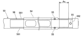
- the substrate camera 15 can take an image by capturing the supply region As in which the bulk feeder 50 supplies the component 80 in the camera field of view Vc.
- the substrate camera 15 can be used for imaging different imaging targets in order to acquire image data used for various image processing.
- the bulk feeder 50 includes a feeder control unit 58 that executes a supply process of the component 80 to the supply area As.
- the feeder control unit 58 controls the operation of the vibration exciter 57 in response to an external command, and supplies the component 80 to the supply area As by transporting the component 80 on the transport path.
- the feeder control unit 58 controls so that, for example, at least a part of the component 80 is retracted from the supply area As to the component case 52 side so that an appropriate amount of the component 80 remains in the supply area As. There is.
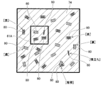
- the position and shape of the search range 65 can be appropriately adjusted according to the position and shape of the feature portion in the component 80. Then, in the processed image data 62, the feature portion located in the predetermined search range 65 has a possibility of belonging to the same component 80 together with the reference feature portion 85, and is recognized as the candidate feature portion 86 as described above. NS. Then, the state recognition unit 23 is based on one or more of the feature amount of one or more candidate feature units 86 included in the search range 65 and the positional relationship between the reference feature unit 85 and the candidate feature unit 86. It is determined whether or not the unit 86 belongs to the same component 80 together with the reference feature unit 85.
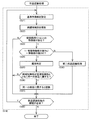
- the state recognition unit 23 executes a part recognition process for recognizing individual parts 80 based on a large number of feature parts in the processed image data 62 (S14).
- the state recognition unit 23 repeatedly executes the above recognition process in the component recognition process until, for example, the required number of components 80 are recognized in the next PP cycle. As a result, the state recognition unit 23 recognizes at least a part of the plurality of parts 80 in the processed image data 62. The details of the component recognition process will be described later.
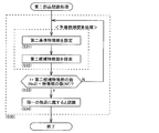
- the state recognition unit 23 searches for the candidate feature unit 86 included in the predetermined search range 65 defined based on the reference feature unit 85 (S22).
- the search range 65 is set to a range in which there is a high possibility that the other terminal 82 exists when the reference feature portion 85 is set to one terminal 82.
- the state recognition unit 23 is the number of feature units including the reference feature unit 85 and the candidate feature unit 86 included in the search range 65 when there is one or more feature units in the search range 65 (S23: Yes). (1 + Ns) is compared with the number of feature portions (Nf) formed in one component 80 (S24).
- the state recognition unit 23 determines that the candidate feature unit 86 belongs to the same component 80 together with the reference feature unit 85. According to such a configuration, even if the design information including the shape of each feature portion is not acquired in advance, the attribute determination can be performed by comparing with the shape of the reference feature portion 85.
- the state recognition unit 23 determines whether or not the candidate feature unit 86 belongs to the same component 80 together with the reference feature unit 85 based on the result of the determination. That is, when the state recognition unit 23 obtains a determination result that the main body unit 81 exists between the reference feature unit 85 and the candidate feature unit 86, the candidate feature unit 86 is combined with the reference feature unit 85. It is determined that they belong to the same component 80.
- the measurement point Pm may be the center position of the component 80, or may be set at a position separated from the center position by a predetermined distance in a predetermined direction.
- a plurality of measurement points Pm may be set from the viewpoint of improving determination accuracy. However, if the difference in brightness between the main body 81 and the background 74 is clear in the image data 61 before processing, it is sufficient to have one measurement point Pm.
- the position and number of measurement points Pm are set for each type of component 80.
- the camera that captures the supply area As of the bulk feeder 50 is a substrate camera 15.
- the component mounting machine 10 may be provided above the bulk feeder 50 and may include a camera capable of capturing the supply area As.
- the camera may be dedicated to imaging the supply area As or may be used for other purposes. According to such a configuration, the camera becomes a fixed type, and the accuracy of the calibration process can be improved.
- the embodiment illustrated in the embodiment is preferable.
Landscapes
- Engineering & Computer Science (AREA)
- Manufacturing & Machinery (AREA)
- Microelectronics & Electronic Packaging (AREA)
- Operations Research (AREA)
- Software Systems (AREA)
- Physics & Mathematics (AREA)
- General Physics & Mathematics (AREA)
- Multimedia (AREA)
- Theoretical Computer Science (AREA)
- Supply And Installment Of Electrical Components (AREA)
Abstract
La présente invention concerne un dispositif de montage de composants comprenant une unité de reconnaissance d'état qui reconnaît un état de fourniture de composants dans une zone de fourniture sur la base d'une caractéristique qui comprend la forme et/ou l'angle de chaque partie caractéristique d'une pluralité de parties caractéristiques dans des données d'image obtenues après le traitement d'image. L'unité de reconnaissance d'état détermine, sur la base de l'une des caractéristiques d'au moins une partie caractéristique candidate comprise dans une plage de recherche et de la relation de position entre une partie caractéristique de référence et une partie caractéristique candidate, si la partie caractéristique candidate et la partie caractéristique de référence appartiennent au même composant.
Priority Applications (5)
| Application Number | Priority Date | Filing Date | Title |
|---|---|---|---|
| US17/904,489 US20230106149A1 (en) | 2020-02-21 | 2020-02-21 | Component mounter |
| CN202080096469.3A CN115088402B (zh) | 2020-02-21 | 2020-02-21 | 元件装配机 |
| JP2022501546A JP7228075B2 (ja) | 2020-02-21 | 2020-02-21 | 部品装着機 |
| PCT/JP2020/006997 WO2021166211A1 (fr) | 2020-02-21 | 2020-02-21 | Dispositif de montage de composants |
| EP20920458.5A EP4110032A4 (fr) | 2020-02-21 | 2020-02-21 | Dispositif de montage de composants |
Applications Claiming Priority (1)
| Application Number | Priority Date | Filing Date | Title |
|---|---|---|---|
| PCT/JP2020/006997 WO2021166211A1 (fr) | 2020-02-21 | 2020-02-21 | Dispositif de montage de composants |
Publications (1)
| Publication Number | Publication Date |
|---|---|
| WO2021166211A1 true WO2021166211A1 (fr) | 2021-08-26 |
Family
ID=77390537
Family Applications (1)
| Application Number | Title | Priority Date | Filing Date |
|---|---|---|---|
| PCT/JP2020/006997 WO2021166211A1 (fr) | 2020-02-21 | 2020-02-21 | Dispositif de montage de composants |
Country Status (5)
| Country | Link |
|---|---|
| US (1) | US20230106149A1 (fr) |
| EP (1) | EP4110032A4 (fr) |
| JP (1) | JP7228075B2 (fr) |
| CN (1) | CN115088402B (fr) |
| WO (1) | WO2021166211A1 (fr) |
Cited By (1)
| Publication number | Priority date | Publication date | Assignee | Title |
|---|---|---|---|---|
| WO2024062597A1 (fr) * | 2022-09-22 | 2024-03-28 | 株式会社Fuji | Dispositif et procédé de reconnaissance de composant |
Citations (4)
| Publication number | Priority date | Publication date | Assignee | Title |
|---|---|---|---|---|
| JPS6245092A (ja) * | 1985-08-23 | 1987-02-27 | 株式会社日立製作所 | 部品位置及び姿勢認識方法及び同認識装置 |
| JP2011114084A (ja) | 2009-11-25 | 2011-06-09 | Nitto Kogyo Co Ltd | 電子部品供給装置 |
| WO2017208325A1 (fr) * | 2016-05-31 | 2017-12-07 | 富士機械製造株式会社 | Système de fourniture de composants |
| JP2018170513A (ja) * | 2018-06-07 | 2018-11-01 | 株式会社Fuji | ばら部品供給装置、部品実装装置およびばら部品供給方法 |
Family Cites Families (14)
| Publication number | Priority date | Publication date | Assignee | Title |
|---|---|---|---|---|
| JP2554431B2 (ja) * | 1992-11-05 | 1996-11-13 | ヤマハ発動機株式会社 | 実装機の部品吸着状態検出装置 |
| US6584683B2 (en) * | 1996-04-18 | 2003-07-01 | Matsushita Electric Industrial Co., Ltd. | Mounting electronic component method and apparatus |
| JP4561562B2 (ja) * | 2005-09-27 | 2010-10-13 | パナソニック株式会社 | 画像認識用データ作成装置および画像認識用データ作成方法 |
| JP5457665B2 (ja) * | 2008-12-22 | 2014-04-02 | 株式会社日立ハイテクインスツルメンツ | 電子部品装着装置 |
| JP2013026385A (ja) * | 2011-07-20 | 2013-02-04 | Hitachi High-Tech Instruments Co Ltd | 電子部品実装装置及び電子部品実装方法 |
| JP5988839B2 (ja) * | 2012-11-15 | 2016-09-07 | 富士機械製造株式会社 | 部品実装機 |
| JP6450923B2 (ja) * | 2013-12-20 | 2019-01-16 | パナソニックIpマネジメント株式会社 | 電子部品実装システムおよび電子部品実装方法ならびに電子部品実装装置 |
| WO2015186188A1 (fr) * | 2014-06-03 | 2015-12-10 | 富士機械製造株式会社 | Dispositif d'approvisionnement en composants en vrac et dispositif de montage de composant |
| JP6245092B2 (ja) | 2014-06-27 | 2017-12-13 | 株式会社オートネットワーク技術研究所 | 電流制御装置 |
| US10314217B2 (en) * | 2015-03-18 | 2019-06-04 | Fuji Corporation | Component supply device |
| WO2018096577A1 (fr) * | 2016-11-22 | 2018-05-31 | 株式会社Fuji | Système et procédé de traitement d'image |
| JP6974101B2 (ja) * | 2017-10-02 | 2021-12-01 | ヤマハ発動機株式会社 | 設定装置、及び、表面実装機 |
| WO2020031366A1 (fr) * | 2018-08-10 | 2020-02-13 | 株式会社Fuji | Dispositif de gestion de machine de montage d'élément |
| JP7439129B2 (ja) * | 2019-12-16 | 2024-02-27 | 株式会社Fuji | 部品装着機 |
-
2020
- 2020-02-21 EP EP20920458.5A patent/EP4110032A4/fr active Pending
- 2020-02-21 JP JP2022501546A patent/JP7228075B2/ja active Active
- 2020-02-21 WO PCT/JP2020/006997 patent/WO2021166211A1/fr unknown
- 2020-02-21 CN CN202080096469.3A patent/CN115088402B/zh active Active
- 2020-02-21 US US17/904,489 patent/US20230106149A1/en active Pending
Patent Citations (4)
| Publication number | Priority date | Publication date | Assignee | Title |
|---|---|---|---|---|
| JPS6245092A (ja) * | 1985-08-23 | 1987-02-27 | 株式会社日立製作所 | 部品位置及び姿勢認識方法及び同認識装置 |
| JP2011114084A (ja) | 2009-11-25 | 2011-06-09 | Nitto Kogyo Co Ltd | 電子部品供給装置 |
| WO2017208325A1 (fr) * | 2016-05-31 | 2017-12-07 | 富士機械製造株式会社 | Système de fourniture de composants |
| JP2018170513A (ja) * | 2018-06-07 | 2018-11-01 | 株式会社Fuji | ばら部品供給装置、部品実装装置およびばら部品供給方法 |
Non-Patent Citations (1)
| Title |
|---|
| See also references of EP4110032A4 |
Cited By (1)
| Publication number | Priority date | Publication date | Assignee | Title |
|---|---|---|---|---|
| WO2024062597A1 (fr) * | 2022-09-22 | 2024-03-28 | 株式会社Fuji | Dispositif et procédé de reconnaissance de composant |
Also Published As
| Publication number | Publication date |
|---|---|
| JPWO2021166211A1 (fr) | 2021-08-26 |
| EP4110032A1 (fr) | 2022-12-28 |
| CN115088402A (zh) | 2022-09-20 |
| CN115088402B (zh) | 2023-06-27 |
| EP4110032A4 (fr) | 2023-03-08 |
| US20230106149A1 (en) | 2023-04-06 |
| JP7228075B2 (ja) | 2023-02-22 |
Similar Documents
| Publication | Publication Date | Title |
|---|---|---|
| US20170151673A1 (en) | Manipulator system, and image capturing system | |
| EP3177130B1 (fr) | Dispositif de prise en charge de données de composants, procédé de prise en charge de données de composants, et système de montage de composants | |
| WO2021166211A1 (fr) | Dispositif de montage de composants | |
| WO2021205578A1 (fr) | Dispositif de traitement d'image, dispositif de montage et procédé de traitement d'image | |
| JP7439129B2 (ja) | 部品装着機 | |
| JPWO2014106892A1 (ja) | 部品実装機及び部品実装方法 | |
| JP2020083584A (ja) | 荷降ろし装置、荷降ろし方法及びプログラム | |
| JP6646916B2 (ja) | 基板用の画像処理装置および画像処理方法 | |
| JP7312903B2 (ja) | 部品装着機 | |
| JPWO2017068638A1 (ja) | 画像処理装置および部品実装機 | |
| US10194570B2 (en) | Mounter and method for inspecting suction posture of electronic component using mounter | |
| CN110121255B (zh) | 发光部件安装装置以及发光部件安装方法 | |
| JPWO2018158888A1 (ja) | バックアップピンの認識方法および部品実装装置 | |
| JP5957238B2 (ja) | 切削装置 | |
| JP2017130592A (ja) | 部品データ取扱装置および部品データ取扱方法並びに部品実装システム | |
| WO2018055663A1 (fr) | Dispositif d'imagerie et dispositif de montage | |
| KR20150066424A (ko) | 인식장치, 인식 방법, 실장 장치 및 실장 방법 | |
| CN110871444B (zh) | 信息处理装置以及信息处理方法 | |
| JP7142092B2 (ja) | テンプレート作成装置および部品装着機 | |
| JP7142169B2 (ja) | 画像データ管理装置および画像データ管理方法 | |
| JP2008078320A (ja) | 電子部品実装方法及び装置 | |
| WO2023188107A1 (fr) | Machine de montage de composant et procédé de montage de composant | |
| JP7153126B2 (ja) | 良否判定装置および良否判定方法 | |
| KR20180065705A (ko) | 부품 실장기 | |
| CN117104870A (zh) | 一种机械手抓取无序堆放鞋底的设备 |
Legal Events
| Date | Code | Title | Description |
|---|---|---|---|
| 121 | Ep: the epo has been informed by wipo that ep was designated in this application |
Ref document number: 20920458 Country of ref document: EP Kind code of ref document: A1 |
|
| ENP | Entry into the national phase |
Ref document number: 2022501546 Country of ref document: JP Kind code of ref document: A |
|
| NENP | Non-entry into the national phase |
Ref country code: DE |
|
| ENP | Entry into the national phase |
Ref document number: 2020920458 Country of ref document: EP Effective date: 20220921 |