WO2021157673A1 - 蓄電デバイス用外装材、その製造方法、及び蓄電デバイス - Google Patents
蓄電デバイス用外装材、その製造方法、及び蓄電デバイス Download PDFInfo
- Publication number
- WO2021157673A1 WO2021157673A1 PCT/JP2021/004183 JP2021004183W WO2021157673A1 WO 2021157673 A1 WO2021157673 A1 WO 2021157673A1 JP 2021004183 W JP2021004183 W JP 2021004183W WO 2021157673 A1 WO2021157673 A1 WO 2021157673A1
- Authority
- WO
- WIPO (PCT)
- Prior art keywords
- layer
- storage device
- power storage
- thickness
- exterior material
- Prior art date
- Legal status (The legal status is an assumption and is not a legal conclusion. Google has not performed a legal analysis and makes no representation as to the accuracy of the status listed.)
- Ceased
Links
Images


Classifications
-
- H—ELECTRICITY
- H01—ELECTRIC ELEMENTS
- H01G—CAPACITORS; CAPACITORS, RECTIFIERS, DETECTORS, SWITCHING DEVICES, LIGHT-SENSITIVE OR TEMPERATURE-SENSITIVE DEVICES OF THE ELECTROLYTIC TYPE
- H01G11/00—Hybrid capacitors, i.e. capacitors having different positive and negative electrodes; Electric double-layer [EDL] capacitors; Processes for the manufacture thereof or of parts thereof
- H01G11/78—Cases; Housings; Encapsulations; Mountings
-
- H—ELECTRICITY
- H01—ELECTRIC ELEMENTS
- H01M—PROCESSES OR MEANS, e.g. BATTERIES, FOR THE DIRECT CONVERSION OF CHEMICAL ENERGY INTO ELECTRICAL ENERGY
- H01M50/00—Constructional details or processes of manufacture of the non-active parts of electrochemical cells other than fuel cells, e.g. hybrid cells
- H01M50/10—Primary casings; Jackets or wrappings
-
- Y—GENERAL TAGGING OF NEW TECHNOLOGICAL DEVELOPMENTS; GENERAL TAGGING OF CROSS-SECTIONAL TECHNOLOGIES SPANNING OVER SEVERAL SECTIONS OF THE IPC; TECHNICAL SUBJECTS COVERED BY FORMER USPC CROSS-REFERENCE ART COLLECTIONS [XRACs] AND DIGESTS
- Y02—TECHNOLOGIES OR APPLICATIONS FOR MITIGATION OR ADAPTATION AGAINST CLIMATE CHANGE
- Y02E—REDUCTION OF GREENHOUSE GAS [GHG] EMISSIONS, RELATED TO ENERGY GENERATION, TRANSMISSION OR DISTRIBUTION
- Y02E60/00—Enabling technologies; Technologies with a potential or indirect contribution to GHG emissions mitigation
- Y02E60/10—Energy storage using batteries
Definitions
- This disclosure relates to an exterior material for a power storage device, a manufacturing method thereof, and a power storage device.
- a packaging material (exterior material) is an indispensable member for sealing the power storage device elements such as electrodes and electrolytes.
- a metal exterior material has been widely used as an exterior material for a power storage device.
- Exterior material for a power storage device that can be easily processed into various shapes and can be made thinner and lighter, it is in the form of a film in which a base material / aluminum foil layer / heat-sealing resin layer is sequentially laminated. Exterior materials have been proposed (see, for example, Patent Document 1).
- a recess is generally formed by cold forming, and a storage device element such as an electrode or an electrolytic solution is arranged in the space formed by the recess to form a heat-sealing resin.
- film-like exterior materials have been required to be further thinned. Further, from the viewpoint of further increasing the energy density of the power storage device, it is also required to form a deep recess in the exterior material.
- a base material layer, a barrier layer, and a heat-sealing resin layer are laminated in this order to form an exterior material for a power storage device, which is molded to form a recess for accommodating the power storage device element.
- the thickness of the exterior material for the power storage device is reduced to 100 ⁇ m or less, the peripheral edge of the recess is curled by molding to accommodate the power storage device element and heat-melt the heat-sealing resin layer. It has been found that it may hinder the wearing and reduce the production efficiency of the power storage device.
- the thickness of the exterior material for the power storage device is reduced to 100 ⁇ m or less, the mechanical strength is lowered, for example, when an external impact is applied to the power storage device (for example, when the power storage device is dropped). In addition, there is a risk that the power storage device element cannot be sufficiently protected.
- the present disclosers focus on the laminated structure of the exterior material for a power storage device in the exterior material for a power storage device designed to have a thickness of 100 ⁇ m or less to suppress molding curl and improve the mechanical strength. Diligently examined. As a result, it has been found that it is possible to provide an exterior material for a power storage device in which molding curl is suppressed and mechanical strength is high as compared with a conventional exterior material for a power storage device.
- the total thickness of the laminate constituting the exterior material for the power storage device is set to 100 ⁇ m or less
- the thickness of the base material layer is set to the range of 18 ⁇ m or more and 22 ⁇ m or less
- the thickness of the barrier layer is 27 ⁇ m or more. It has been found that by setting the range to 38 ⁇ m or less, the thickness is thin, curling due to molding is suppressed, and the exterior material for a power storage device having high mechanical strength can be obtained.
- the present disclosure provides the inventions of the following aspects. It is composed of a laminate having at least a base material layer, a barrier layer, and a heat-sealing resin layer in this order.
- the thickness of the base material layer is 18 ⁇ m or more and 22 ⁇ m or less.
- the thickness of the barrier layer is 27 ⁇ m or more and 38 ⁇ m or less.
- An exterior material for a power storage device having a thickness of 100 ⁇ m or less.
- the thickness is as thin as 100 ⁇ m or less, curling due to molding is suppressed, and it is possible to provide an exterior material for a power storage device having high mechanical strength. Further, according to the present disclosure, it is also possible to provide a method for manufacturing an exterior material for a power storage device and a power storage device.
- the exterior material for a power storage device of the present disclosure is composed of a laminate having at least a base material layer, a barrier layer, and a heat-sealing resin layer in this order, and the thickness of the base material layer is 18 ⁇ m or more and 22 ⁇ m or less.
- the barrier layer is 27 ⁇ m or more and 38 ⁇ m or less, and the laminated body is 100 ⁇ m or less.
- the exterior material for the power storage device of the present disclosure will be described in detail.
- the numerical range indicated by “-" means “greater than or equal to” and “less than or equal to”.
- the notation of 2 to 15 mm means 2 mm or more and 15 mm or less.
- the thickness of each layer constituting the laminated body shall be a value rounded to the first decimal place.
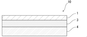
- the exterior material 10 for power storage device of the present disclosure includes, for example, a base material layer 1, a barrier layer 3, and a heat-sealing resin layer 4 in this order, as shown in FIG. It is composed of a laminated body.
- the base material layer 1 is on the outermost layer side
- the heat-sealing resin layer 4 is on the innermost layer.
- the peripheral portion is heat-sealed with the heat-sealing resin layers 4 of the power storage device exterior material 10 facing each other.
- the power storage device element is housed in the space formed by.
- the heat-sealing resin layer 4 side is inside the barrier layer 3 and the base material layer 1 side is more than the barrier layer 3 with the barrier layer 3 as a reference. It is the outside.
- the exterior material 10 for a power storage device is used as necessary for the purpose of enhancing the adhesiveness between the base material layer 1 and the barrier layer 3 and the like. It may have an adhesive layer 2. Further, for example, as shown in FIGS. 3 and 4, the adhesive layer 5 is required between the barrier layer 3 and the heat-sealing resin layer 4 for the purpose of enhancing the adhesiveness between the layers. May have. Further, as shown in FIG. 4, a surface coating layer 6 or the like may be provided on the outside of the base material layer 1 (the side opposite to the heat-sealing resin layer 4 side), if necessary.
- the laminated structure of the exterior material 10 for the power storage device a laminated structure in which the base material layer 1 / barrier layer 3 / heat-sealing resin layer 4 are laminated in this order; the base material layer 1 / adhesive layer 2 / A laminated structure in which the barrier layer 3 / heat-sealing resin layer 4 is laminated in this order; a laminated structure in which the base material layer 1 / barrier layer 3 / adhesive layer 5 / heat-sealing resin layer 4 are laminated in this order; A laminated structure in which the material layer 1 / adhesive layer 2 / barrier layer 3 / adhesive layer 5 / heat-sealing resin layer 4 are laminated in this order; surface coating layer 6 / base material layer 1 / barrier layer 3 / heat fusion Laminated structure in which the sex resin layers 4 are laminated in this order; Laminated structure in which the surface coating layer 6 / base material layer 1 / adhesive layer 2 / barrier layer 3 / heat-sealing resin
- the lubricant may be present on at least one surface of the outside of the base material layer 1 and the inside of the heat-sealing resin layer 4. Further, in the laminated structure in which the surface coating layer 6 is the outermost layer, the lubricant may be present on at least one surface of the outside of the surface coating layer 6 and the inside of the heat-sealing resin layer 4. The lubricant will be described later.
- the thickness of the laminate constituting the exterior material for the power storage device of the present disclosure is set to 100 ⁇ m or less.
- the thickness of the laminated body is set to 100 ⁇ m or less, and then the thickness of the base material layer 1 and the barrier layer 3 described later is set to a specific range, respectively.
- the thickness of the laminate is preferably about 75 ⁇ m or more from the viewpoint of appropriately suppressing curling due to molding while preferably reducing the thickness of the exterior material for the power storage device and further preferably exhibiting high mechanical strength.
- the thickness of the laminate is preferably about 98 ⁇ m or less, more preferably about 95 ⁇ m or less, still more preferably about 93 ⁇ m or less, still more preferably about 91 ⁇ m or less.
- the preferable range of the thickness of the laminate is about 75 to 100 ⁇ m, about 75 to 98 ⁇ m, about 75 to 95 ⁇ m, about 75 to 93 ⁇ m, about 75 to 91 ⁇ m, about 77 to 100 ⁇ m, about 77 to 98 ⁇ m, about 77 to 95 ⁇ m, and so on.
- the base material layer 1, the adhesive layer 2 provided as necessary, the barrier layer 3 are required with respect to the thickness (total thickness) of the laminate constituting the exterior material for the power storage device.
- the ratio of the total thickness of the adhesive layer 5, the heat-sealing resin layer 4, and the surface coating layer 6 provided as needed is preferably 90% or more, more preferably 95% or more. More preferably, it is 98% or more.
- the exterior material for a power storage device of the present disclosure includes a base material layer 1, an adhesive layer 2, a barrier layer 3, an adhesive layer 5, and a heat-sealing resin layer 4, the exterior material for a power storage device is included.
- the ratio of the total thickness of each of these layers to the thickness (total thickness) of the laminate constituting 10 is preferably 90% or more, more preferably 95% or more, and further preferably 98% or more. Further, even when the exterior material for a power storage device of the present disclosure includes a base material layer 1, an adhesive layer 2, a barrier layer 3, and a heat-sealing resin layer 4, the laminate constituting the exterior material 10 for a power storage device is also formed.
- the ratio of the total thickness of each of these layers to the body thickness (total thickness) is preferably 90% or more, more preferably 95% or more, and further preferably 98% or more.
- the total thickness of the layers located inside the barrier layer 3 is preferably about 20 ⁇ m or more, more preferably about 22 ⁇ m or more. It is more preferably about 24 ⁇ m or more, still more preferably about 28 ⁇ m or more.
- the total thickness is preferably about 40 ⁇ m or less, more preferably about 38 ⁇ m or less, still more preferably about 35 ⁇ m or less.
- the preferable range of the total thickness is about 20 to 40 ⁇ m, about 20 to 38 ⁇ m, about 20 to 35 ⁇ m, about 22 to 40 ⁇ m, about 22 to 38 ⁇ m, about 22 to 35 ⁇ m, about 24 to 40 ⁇ m, about 24 to 38 ⁇ m, 24. Examples thereof include about 35 ⁇ m, about 28 to 40 ⁇ m, about 28 to 38 ⁇ m, and about 28 to 35 ⁇ m.
- each layer of the exterior material for the power storage device or the thickness of the laminate of the present disclosure is such that the exterior material for the power storage device is cut in the thickness direction using, for example, a microtome (manufactured by Daiwa Kouki Kogyo: REM-710 Litratome). Then, the exterior material for the power storage device is divided into two parts, and the obtained cross section can be observed and measured with, for example, a laser microscope (manufactured by KEYENCE: VK-9700).
- the barrier layer 3 described later in the exterior material for a power storage device it is usually possible to discriminate between MD (Machine Direction) and TD (Transverse Direction) in the manufacturing process thereof.
- MD Machine Direction
- TD Transverse Direction
- the barrier layer 3 is made of aluminum foil
- linear streaks so-called rolling marks
- the rolling marks extend along the rolling direction
- the rolling direction of the aluminum foil can be grasped by observing the surface of the aluminum foil.
- the MD of the laminated body and the RD of the aluminum foil usually match, the surface of the aluminum foil of the laminated body is observed and the rolling direction (RD) of the aluminum foil is specified.
- the MD of the laminated body can be specified.
- the TD of the laminated body is in the direction perpendicular to the MD of the laminated body, the TD of the laminated body can also be specified.
- the piercing strength from the outer surface side (base material layer side or surface coating layer side) of the laminate constituting the exterior material for the power storage device is preferably 19 N or more, more preferably 23 N or more.
- the piercing strength is, for example, 30 N or less.
- the piercing strength is adjusted by, for example, the laminated structure of the exterior material for the power storage device, the thickness of the base material layer 1, the stretching ratio at the time of manufacturing the base material layer 1, the heat fixing temperature, and the like.
- the method for measuring the piercing strength is as follows.
- the measuring device for example, ZP-50N (force gauge) manufactured by Imada and MX2-500N (measurement stand) manufactured by Imada can be used.
- ZP-50N force gauge
- MX2-500N measurement stand manufactured by Imada
- the test piece was fixed with a stand with a diameter of 115 mm and a holding plate having an opening with a diameter of 15 mm in the center, and the diameter was 1.0 mm and the tip shape radius was 0.5 mm.
- the semi-circular needle is pierced at a speed of 50 ⁇ 5 mm per minute, and the maximum stress until the needle penetrates is measured.
- the number of test pieces is 10 each, and the average value is calculated. If the number of test pieces is insufficient and 10 cannot be measured, the measurable number is measured and the average value is calculated. It can be said that when the piercing strength is 19 N or more, the mechanical strength is sufficiently high, and when it is 23 N or more, the mechanical strength is particularly high.
- the coefficient of kinetic friction of the outer surface (surface on the base material layer side or the surface coating layer side) of the exterior material for a power storage device is preferably about 0.01 or more, more preferably about 0.05 or more, and further preferably about 0. It is .09 or more.
- the coefficient of dynamic friction is preferably about 0.80 or less, more preferably about 0.50 or less, and even more preferably about 0.25 or less.
- the preferable ranges of the dynamic friction coefficient are about 0.01 to 0.80, about 0.01 to 0.50, about 0.01 to 0.25, about 0.05 to 0.80, and 0.05 to 0. Examples thereof include about .50, about 0.05 to 0.25, about 0.09 to 0.80, about 0.09 to 0.50, and about 0.09 to 0.25.
- the dynamic friction coefficient is adjusted by adjusting the material of the layer constituting the outer surface of the exterior material for the power storage device, the lubricant, and the like.
- the method for measuring the dynamic friction coefficient is as follows.
- ⁇ Dynamic friction coefficient> The coefficient of kinetic friction is measured by a method similar to that of JIS K7125: 1999 8.1 film-to-film measurement. Two pieces of the exterior material for the power storage device are cut into a sample of 80 mm in the TD direction and 200 mm in the MD direction. Next, the samples are stacked so that the outer surfaces face each other, and a sliding piece is placed on the sample. Rubber is attached to the bottom surface of the sliding piece so that the total mass of the sliding piece is 200 g, and the sample and the sliding piece are also brought into close contact with each other to prevent slipping.
- the sliding piece is pulled at a speed of 100 mm / min, the dynamic friction force (N) between the two samples is measured, and the dynamic friction force is divided by the normal force (1.96N) of the sliding piece to obtain the dynamic friction coefficient. Is calculated.
- the coefficient of kinetic friction is obtained from the average value up to the first 30 mm after the start of the relative displacement motion between the contact surfaces, ignoring the peak of the static friction force.
- the load cell is directly connected to the sliding piece.
- the number of times until a pinhole is formed in the central portion is preferably 5 times or more, preferably 7 times or more. It is more preferable than that. It can be said that when the number of times is 5 times or more, the mechanical strength of the exterior material for the power storage device is sufficiently high, and when the number of times is 7 times or more, the mechanical strength of the exterior material for the power storage device is particularly high.
- ⁇ Fold test in four> The exterior material for the power storage device is cut to prepare a strip piece of TD150 mm ⁇ MD90 mm, which is used as a test sample.
- the work of folding the test sample in four is performed 10 times, and the number of times until a pinhole is formed in the central portion is measured.
- the short sides (sides in the MD direction) of the test sample are folded in half at the center position in the TD direction so that the heat-sealing resin layers overlap each other, and further, the center in the MD direction is folded. Fold it in half so that the sides in the TD direction overlap at the position, and perform the operation of folding the center position of the test sample in four, and fold it in four once.
- test is performed by repeating the same work of folding the test sample in four and opening the test sample.
- the number of test samples is 5 each, and the average value of the number of times until a pinhole is formed in the central portion is calculated. If the number of test samples is insufficient and 5 cannot be measured, the measurable number is measured and the average value is calculated.
- the base material layer 1 is a layer provided for the purpose of exerting a function as a base material of an exterior material for a power storage device.
- the base material layer 1 is located on the outer layer side of the exterior material for the power storage device.
- the base material layer 1 may be the outermost layer (layer constituting the outer surface).
- the surface coating layer 6 is the outermost layer (layer constituting the outer surface). ) May be.
- the thickness of the base material layer 1 is set in a specific range of 18 to 22 ⁇ m.
- the thickness of the base material layer 1 is preferably about 19 ⁇ m or more from the viewpoint of suitably exhibiting high mechanical strength while suitably suppressing curling due to molding. Is. From the same viewpoint, the thickness of the base material layer 1 is preferably about 21 ⁇ m or less. Preferred ranges of the thickness of the base material layer 1 include about 18 to 21 ⁇ m, about 19 to 22 ⁇ m, and about 19 to 21 ⁇ m.
- the base material layer 1 is composed of two or more layers and these layers are adhered by an adhesive layer such as an adhesive layer, the total thickness of the base material layer 1 is determined. , The thickness of the layer of the adhesive shall not be included.
- the material forming the base material layer 1 is not particularly limited as long as it has a function as a base material, that is, at least an insulating property.
- the base material layer 1 can be formed by using, for example, a resin, and the resin may contain an additive described later.
- the base material layer 1 may be, for example, a resin film formed of resin or may be formed by applying a resin.
- the resin film may be an unstretched film or a stretched film.
- the stretched film include a uniaxially stretched film and a biaxially stretched film, and a biaxially stretched film is preferable.
- the stretching method for forming the biaxially stretched film include a sequential biaxial stretching method, an inflation method, and a simultaneous biaxial stretching method.
- the method for applying the resin include a roll coating method, a gravure coating method, and an extrusion coating method.
- the resin forming the base material layer 1 examples include resins such as polyester, polyamide, polyolefin, epoxy resin, acrylic resin, fluororesin, polyurethane, silicon resin, and phenol resin, and modified products of these resins. Further, the resin forming the base material layer 1 may be a copolymer of these resins or a modified product of the copolymer. Further, it may be a mixture of these resins.
- the resin forming the base material layer 1 include polyester and polyamide.
- polyester examples include polyethylene terephthalate, polybutylene terephthalate, polyethylene naphthalate, polybutylene naphthalate, polyethylene isophthalate, and copolymerized polyester.
- copolymerized polyester examples include a copolymerized polyester containing ethylene terephthalate as a repeating unit as a main component.
- copolymer polyester (hereinafter abbreviated after polyethylene (terephthalate / isophthalate)), polyethylene (terephthalate / adipate), polyethylene (terephthalate / terephthalate / (Sodium sulfoisophthalate), polyethylene (terephthalate / sodium isophthalate), polyethylene (terephthalate / phenyl-dicarboxylate), polyethylene (terephthalate / decandicarboxylate) and the like.
- polyesters may be used alone or in combination of two or more.
- polyamide examples include an aliphatic polyamide such as nylon 6, nylon 66, nylon 610, nylon 12, nylon 46, and a copolymer of nylon 6 and nylon 66; terephthalic acid and / or isophthalic acid.
- Hexamethylenediamine-isophthalic acid-terephthalic acid copolymerized polyamide such as nylon 6I, nylon 6T, nylon 6IT, nylon 6I6T (I stands for isophthalic acid, T stands for terephthalic acid), polyamide MXD6 (polymethaki Polyamide containing aromatics such as silylene adipamide); Alicyclic polyamide such as polyamide PACM6 (polybis (4-aminocyclohexyl) methaneadipamide); Further, lactam component and isocyanate component such as 4,4'-diphenylmethane-diisocyanate Examples thereof include copolymerized polyamides, polyesteramide copolymers and polyether esteramide copolymers which are copoly
- the base material layer 1 preferably contains at least one of a polyester film, a polyamide film, and a polyolefin film, and preferably contains at least one of a stretched polyester film, a stretched polypropylene film, and a stretched polyolefin film. It is more preferable to contain at least one of a stretched polyethylene terephthalate film, a stretched polybutylene terephthalate film, a stretched nylon film, and a stretched polypropylene film, preferably a biaxially stretched polyethylene terephthalate film, a biaxially stretched polybutylene terephthalate film, and a biaxially stretched nylon film. , It is more preferable to contain at least one of the biaxially stretched polypropylene films.
- the base material layer 1 may be a single layer or may be composed of two or more layers.
- the base material layer 1 may be a laminated body in which a resin film is laminated with an adhesive or the like, or the resin is co-extruded to form two or more layers. It may be a laminated body of the resin film. Further, the laminated body of the resin film obtained by co-extruding the resin into two or more layers may be used as the base material layer 1 without being stretched, or may be uniaxially stretched or biaxially stretched as the base material layer 1.
- the laminate of two or more layers of resin film in the base material layer 1 include a laminate of a polyester film and a nylon film, a laminate of two or more layers of nylon film, and a laminate of two or more layers of polyester film. And the like, preferably, a laminate of a stretched nylon film and a stretched polyester film, a laminate of two or more layers of stretched nylon film, and a laminate of two or more layers of stretched polyester film are preferable.
- the base material layer 1 is a laminate of two layers of resin film, the laminate of polyester resin film and polyester resin film, the laminate of polyamide film and polyamide film, or the laminate of polyester resin film and polyamide film is A laminate of a polyethylene terephthalate film and a polyethylene terephthalate film, a laminate of a nylon film and a nylon film, or a laminate of a polyethylene terephthalate film and a nylon film is more preferable.
- the polyester resin is difficult to discolor when the electrolytic solution adheres to the surface, for example, when the base material layer 1 is a laminate of two or more resin films, the polyester resin film is the base material layer 1. It is preferably located in the outermost layer.
- the two or more layers of resin films may be laminated via an adhesive.
- Preferred adhesives include those similar to the adhesives exemplified in the adhesive layer 2 described later.
- the method of laminating two or more layers of resin films is not particularly limited, and known methods can be adopted. Examples thereof include a dry laminating method, a sandwich laminating method, an extrusion laminating method, and a thermal laminating method, and a dry laminating method is preferable.
- the laminating method can be mentioned.
- the thickness of the adhesive is, for example, about 2 to 5 ⁇ m.
- an anchor coat layer may be formed on the resin film and laminated. Examples of the anchor coat layer include the same adhesives as those exemplified in the adhesive layer 2 described later. At this time, the thickness of the anchor coat layer is, for example, about 0.01 to 1.0 ⁇ m. The thickness of the anchor coat layer is not included in the thickness of the base material layer 1.
- the base material layer 1 is made of a single-layer nylon film from the viewpoint of suitably exhibiting high mechanical strength while suitably suppressing curling due to molding. It is preferable that it is.
- the crystallization index of the polyamide film measured from the outside of the base material layer 1 by the ATR method of Fourier transform infrared spectroscopy may be 1.50 or more. preferable.
- the method for measuring the crystallization index of the base material layer 1 of the exterior material 10 for a power storage device of the present disclosure is as follows.
- a sample is prepared by cutting the exterior material for a power storage device into a square of 100 mm ⁇ 100 mm.
- the surface of the polyamide film located on the outside of the obtained sample is subjected to infrared absorption spectrum measurement in an environment of a temperature of 25 ° C. and a relative humidity of 50% using the ATR measurement mode of FT-IR.
- Thermo Fisher Scientific Co., Ltd .: Nicolet iS10 can be used as the apparatus.
- the peak intensity P around 1200 cm -1 derived from the absorption of ⁇ crystals of nylon and the peak intensity Q around 1370 cm -1 derived from the absorption unrelated to the crystals were measured, and the peak intensity Q was measured.
- the intensity ratio X P / Q of the peak intensity P with respect to is calculated as the crystallization index.
- the exterior material 10 for the power storage device can be used as it is as the measurement target of the crystallization index.
- the base material layer 1 has a multilayer structure as described above and a resin film (for example, a polyester film) different from the polyamide film is located outside the polyamide film, or when the base material layer 1 has a multilayer structure.
- the outer surface of the exterior material 10 for a power storage device is not composed of the polyamide film of the base material layer 1, such as when the surface coating layer 6 described later is laminated on the outside, the position is located outside the polyamide film.
- the crystallization index can be measured in a state where the layer is removed from the exterior material 10 for a power storage device and the surface of the polyamide film is exposed.
- the crystallization index may be 1.50 or more, but it is high while preferably suppressing curling due to molding despite the thin thickness of the exterior material for a power storage device. From the viewpoint of preferably exerting mechanical strength, it is more preferably 1.55 or more, further preferably 1.60 or more, still more preferably 1.65 or more, and particularly preferably 1.69 or more.
- the upper limit of the crystallization index is not particularly limited, and examples thereof include 2.50 or less and 1.80 or less.
- Preferred ranges of the crystallization index include, for example, 1.50 to 2.50, 1.60 to 2.50, 1.65 to 2.50, 1.69 to 2.50, and 1.50 to 1. Examples thereof include 80, 1.60 to 1.80, 1.65 to 1.80, and 1.69 to 1.80.
- the draw ratio, the heat fixing temperature, and the post-heating in the manufacturing process of the polyamide film are used.
- Examples thereof include a method of promoting crystallization (promoting the formation of ⁇ -crystals) depending on the temperature and time of the film.
- additives such as a lubricant, a flame retardant, an antiblocking agent, an antioxidant, a light stabilizer, a tackifier, and an antistatic agent are present on at least one of the surface and the inside of the base material layer 1. good. Only one type of additive may be used, or two or more types may be mixed and used.
- the lubricant is present on the surface of the base material layer 1.
- the lubricant is not particularly limited, but an amide-based lubricant is preferable.
- Specific examples of the amide-based lubricant include saturated fatty acid amides, unsaturated fatty acid amides, substituted amides, methylol amides, saturated fatty acid bisamides, unsaturated fatty acid bisamides, fatty acid ester amides, and aromatic bisamides.
- saturated fatty acid amide examples include lauric acid amide, palmitate amide, stearic acid amide, bechenic acid amide, hydroxystearic acid amide and the like.
- unsaturated fatty acid amides include oleic acid amides and erucic acid amides.
- substituted amide examples include N-oleyl palmitate amide, N-stearyl stearic acid amide, N-stearyl oleic acid amide, N-oleyl stearic acid amide, N-stearyl erucate amide and the like.
- methylolamide examples include methylolstearic amide.
- saturated fatty acid bisamide examples include methylene bisstearic acid amide, ethylene biscapric acid amide, ethylene bislauric acid amide, ethylene bisstearic acid amide, ethylene bishydroxystearic acid amide, ethylene bisbechenic acid amide, and hexamethylene bisstearic.
- saturated fatty acid bisamide examples include acid amides, hexamethylene bisbechenic acid amides, hexamethylene hydroxystearic acid amides, N, N'-distearyl adipate amides, and N, N'-distearyl sebacic acid amides.
- unsaturated fatty acid bisamides include ethylene bisoleic acid amide, ethylene biserucic acid amide, hexamethylene bisoleic acid amide, N, N'-diorail adipate amide, and N, N'-diorail sebacic acid amide. And so on.
- Specific examples of the fatty acid ester amide include stearoamide ethyl stearate and the like.
- Specific examples of the aromatic bisamide include m-xylylene bisstearic acid amide, m-xylylene bishydroxystearic acid amide, and N, N'-distearyl isophthalic acid amide.
- One type of lubricant may be used alone, or two or more types may be used in combination.
- the abundance thereof is not particularly limited, but is preferably about 3 mg / m 2 or more, more preferably about 4 to 15 mg / m 2 , and further preferably 5 to 14 mg. / M 2 is mentioned.
- the lubricant existing on the surface of the base material layer 1 may be one in which the lubricant contained in the resin constituting the base material layer 1 is exuded, or one in which the lubricant is applied to the surface of the base material layer 1. You may. Further, the lubricant existing on the surface of the base material layer 1 is a wound body in which the exterior material for the power storage device is wound around a winding core or the like, and the lubricant existing on the surface of the heat-sealing resin layer 4 is a lubricant. It may be transferred to the surface of the base material layer 1.
- the adhesive layer 2 is a layer provided between the base material layer 1 and the barrier layer 3 as necessary for the purpose of enhancing the adhesiveness between the base material layer 1 and the barrier layer 3.
- the adhesive layer 2 is formed by an adhesive capable of adhering the base material layer 1 and the barrier layer 3.
- the adhesive used for forming the adhesive layer 2 is not limited, but may be any of a chemical reaction type, a solvent volatile type, a heat melting type, a hot pressure type and the like. Further, it may be a two-component curable adhesive (two-component adhesive), a one-component curable adhesive (one-component adhesive), or a resin that does not involve a curing reaction. Further, the adhesive layer 2 may be a single layer or a multilayer.
- the adhesive component contained in the adhesive include polyesters such as polyethylene terephthalate, polybutylene terephthalate, polyethylene naphthalate, polybutylene naphthalate, polyethylene isophthalate, and copolymerized polyester; polyether; polyurethane; epoxy resin; Phenolic resin; Polyethylene such as nylon 6, nylon 66, nylon 12, copolymerized polyamide; Polyethylene resin such as polyolefin, cyclic polyolefin, acid-modified polyolefin, acid-modified cyclic polyolefin; Polyvinyl acetate; Cellulose; (Meta) acrylic resin; Polyethylene; polycarbonate; amino resin such as urea resin and melamine resin; rubber such as chloroprene rubber, nitrile rubber and styrene-butadiene rubber; silicone resin and the like.
- polyesters such as polyethylene terephthalate, polybutylene terephthalate, polyethylene naphthalate, polybutylene
- adhesive components may be used alone or in combination of two or more.
- a polyurethane adhesive is preferable.
- the resins used as these adhesive components can be used in combination with an appropriate curing agent to increase the adhesive strength.
- An appropriate curing agent is selected from polyisocyanate, polyfunctional epoxy resin, oxazoline group-containing polymer, polyamine resin, acid anhydride and the like, depending on the functional group of the adhesive component.
- polyurethane adhesive examples include a polyurethane adhesive containing a main agent containing a polyol compound and a curing agent containing an isocyanate compound.
- a polyurethane adhesive containing a main agent containing a polyol compound examples include two-component curable polyurethane adhesives containing a polyol such as a polyester polyol, a polyether polyol, and an acrylic polyol as a main component and an aromatic or aliphatic polyisocyanate as a curing agent.
- a polyol compound it is preferable to use a polyester polyol having a hydroxyl group in the side chain in addition to the hydroxyl group at the end of the repeating unit.
- Examples of the curing agent include aliphatic, alicyclic, aromatic, and aromatic aliphatic isocyanate compounds.
- Examples of the isocyanate-based compound include hexamethylene diisocyanate (HDI) xylylene diisocyanate (XDI), isophorone diisocyanate (IPDI), hydrogenated XDI (H6XDI), hydrogenated MDI (H12MDI), tolylene diisocyanate (TDI), and diphenylmethane diisocyanate ( MDI), naphthalenediocyanate (NDI) and the like.
- HDI hexamethylene diisocyanate
- XDI xylylene diisocyanate
- IPDI isophorone diisocyanate
- H6XDI hydrogenated XDI
- H12MDI hydrogenated MDI
- TDI tolylene diisocyanate
- MDI diphenylmethane diisocyanate
- a multimer for example, a trimer
- a multimer include an adduct body, a biuret body, a nurate body and the like. Since the adhesive layer 2 is formed of the polyurethane adhesive, excellent electrolytic solution resistance is imparted to the exterior material for the power storage device, and even if the electrolytic solution adheres to the side surface, the base material layer 1 is suppressed from peeling off. ..
- the adhesive layer 2 may contain a colorant, a thermoplastic elastomer, a tackifier, a filler, etc., as long as the addition of other components is permitted as long as the adhesiveness is not impaired. Since the adhesive layer 2 contains a colorant, the exterior material for the power storage device can be colored. As the colorant, known ones such as pigments and dyes can be used. Further, only one type of colorant may be used, or two or more types may be mixed and used.
- the type of pigment is not particularly limited as long as it does not impair the adhesiveness of the adhesive layer 2.
- organic pigments include azo-based, phthalocyanine-based, quinacridone-based, anthracinone-based, dioxazine-based, indigothioindigo-based, perinone-perylene-based, isowearnine-based, and benzimidazolone-based pigments, which are inorganic.
- the pigment include carbon black-based, titanium oxide-based, cadmium-based, lead-based, chromium oxide-based, and iron-based pigments, and other examples include fine powder of mica (mica) and fish scale foil.
- carbon black is preferable in order to make the appearance of the exterior material for the power storage device black, for example.
- the average particle size of the pigment is not particularly limited, and examples thereof include about 0.05 to 5 ⁇ m, preferably about 0.08 to 2 ⁇ m.
- the average particle size of the pigment is the median diameter measured by a laser diffraction / scattering type particle size distribution measuring device.
- the content of the pigment in the adhesive layer 2 is not particularly limited as long as the exterior material for the power storage device is colored, and examples thereof include about 5 to 60% by mass, preferably 10 to 40% by mass.
- the thickness of the adhesive layer 2 is not particularly limited as long as the base material layer 1 and the barrier layer 3 can be adhered to each other, but is, for example, about 1 ⁇ m or more and about 2 ⁇ m or more.
- the thickness of the adhesive layer 2 is, for example, about 10 ⁇ m or less and about 5 ⁇ m or less.
- the preferable range of the thickness of the adhesive layer 2 is about 1 to 10 ⁇ m, about 1 to 5 ⁇ m, about 2 to 10 ⁇ m, and about 2 to 5 ⁇ m.
- the colored layer is a layer provided between the base material layer 1 and the barrier layer 3 as needed (not shown).
- a colored layer may be provided between the base material layer 1 and the adhesive layer 2 and between the adhesive layer 2 and the barrier layer 3. Further, a colored layer may be provided on the outside of the base material layer 1. By providing the colored layer, the exterior material for the power storage device can be colored.
- the colored layer can be formed, for example, by applying an ink containing a colorant to the surface of the base material layer 1 or the surface of the barrier layer 3.
- a colorant known ones such as pigments and dyes can be used. Further, only one type of colorant may be used, or two or more types may be mixed and used.
- colorant contained in the colored layer include the same as those exemplified in the column of [Adhesive layer 2].
- the barrier layer 3 is at least a layer that suppresses the infiltration of water.
- Examples of the barrier layer 3 include a metal foil having a barrier property, a thin-film deposition film, a resin layer, and the like.
- Examples of the vapor deposition film include a metal vapor deposition film, an inorganic oxide vapor deposition film, a carbon-containing inorganic oxide vapor deposition film, and the like
- examples of the resin layer include polymers and tetras mainly composed of polyvinylidene chloride and chlorotrifluoroethylene (CTFE). Examples thereof include polymers containing fluoroethylene (TFE) as a main component, polymers having a fluoroalkyl group, fluorine-containing resins such as polymers containing fluoroalkyl units as a main component, and ethylene vinyl alcohol copolymers.
- examples of the barrier layer 3 include a resin film provided with at least one of these vapor-deposited films and a resin layer.
- a plurality of barrier layers 3 may be provided.
- the barrier layer 3 preferably includes a layer made of a metal material.
- Specific examples of the metal material constituting the barrier layer 3 include an aluminum alloy, stainless steel, titanium steel, and a steel plate.
- the metal material includes at least one of an aluminum alloy foil and a stainless steel foil. Is preferable.
- the aluminum alloy foil is more preferably a soft aluminum alloy foil composed of, for example, an aluminum alloy that has been annealed, and the viewpoint of further improving the moldability. Therefore, it is preferable that the aluminum alloy foil contains iron.
- the iron content is preferably 0.1 to 9.0% by mass, more preferably 0.5 to 2.0% by mass.
- the iron content is 0.1% by mass or more, an exterior material for a power storage device having more excellent moldability can be obtained.
- the iron content is 9.0% by mass or less, a more flexible exterior material for a power storage device can be obtained.
- the soft aluminum alloy foil examples include an aluminum alloy having a composition specified by JIS H4160: 1994 A8021HO, JIS H4160: 1994 A8079HO, JIS H4000: 2014 A8021PO, or JIS H4000: 2014 A8077P-O. Foil is mentioned. Further, if necessary, silicon, magnesium, copper, manganese and the like may be added. Further, softening can be performed by annealing or the like.
- stainless steel foils examples include austenite-based, ferrite-based, austenite-ferritic-based, martensitic-based, and precipitation-hardened stainless steel foils. Further, from the viewpoint of providing an exterior material for a power storage device having excellent moldability, the stainless steel foil is preferably made of austenitic stainless steel.
- austenitic stainless steel constituting the stainless steel foil include SUS304, SUS301, and SUS316L, and among these, SUS304 is particularly preferable.
- the thickness of the barrier layer 3 is set in a specific range of 27 to 38 ⁇ m.
- the thickness of the barrier layer 3 is preferably 28 ⁇ m or more, from the viewpoint of suitably exhibiting high mechanical strength while suitably suppressing curling due to molding. It is preferably about 30 ⁇ m or more, more preferably 33 ⁇ m or more. From the same viewpoint, the thickness of the barrier layer is preferably 37 ⁇ m or less, more preferably 36 ⁇ m or less.
- the preferable range of the thickness of the barrier layer is about 27 to 37 ⁇ m, about 27 to 36 ⁇ m, about 28 to 38 ⁇ m, about 28 to 37 ⁇ m, about 28 to 36 ⁇ m, about 30 to 38 ⁇ m, about 30 to 37 ⁇ m, about 30 to 36 ⁇ m, and so on. Examples thereof include about 33 to 38 ⁇ m, about 33 to 37 ⁇ m, and about 33 to 36 ⁇ m.
- the barrier layer 3 is a metal foil, it is preferable that a corrosion-resistant film is provided on at least the surface opposite to the base material layer in order to prevent dissolution and corrosion.
- the barrier layer 3 may be provided with a corrosion-resistant film on both sides.
- the corrosion-resistant film is, for example, a hot water transformation treatment such as boehmite treatment, a chemical conversion treatment, anodizing treatment, a plating treatment such as nickel or chromium, and a corrosion prevention treatment for applying a coating agent on the surface of the barrier layer.
- a hot water transformation treatment such as boehmite treatment
- a chemical conversion treatment such as boehmite treatment
- anodizing treatment such as boehmite treatment
- a plating treatment such as nickel or chromium
- a corrosion prevention treatment for applying a coating agent on the surface of the barrier layer.
- a thin film that makes the barrier layer provided with corrosion resistance (for example, acid resistance, alkali resistance, etc.).
- the corrosion-resistant film means a film for improving the acid resistance of the barrier layer (acid-resistant film), a film for improving the alkali resistance of the barrier layer (alkali-resistant film), and the like.
- the treatment for forming the corrosion-resistant film one type may be performed, or two or more types may be combined. Moreover, not only one layer but also multiple layers can be used.
- the hydrothermal modification treatment and the anodizing treatment are treatments in which the surface of the metal foil is dissolved by a treatment agent to form a metal compound having excellent corrosion resistance. In addition, these processes may be included in the definition of chemical conversion process.
- the barrier layer 3 has a corrosion-resistant film
- the barrier layer 3 includes the corrosion-resistant film.
- the corrosion-resistant film is formed by preventing delamination between the barrier layer (for example, aluminum alloy foil) and the base material layer during molding of the exterior material for a power storage device, and by hydrogen fluoride generated by the reaction between the electrolyte and water. , Melting and corrosion of the surface of the barrier layer, especially when the barrier layer is an aluminum alloy foil, it prevents the aluminum oxide existing on the surface of the barrier layer from melting and corroding, and the adhesiveness (wetness) of the surface of the barrier layer. The effect of preventing the corrosion between the base material layer and the barrier layer at the time of heat sealing and the prevention of the corrosion between the base material layer and the barrier layer at the time of molding is shown.
- the barrier layer for example, aluminum alloy foil
- Various corrosion-resistant films formed by chemical conversion treatment are known, and mainly, at least one of phosphate, chromate, fluoride, triazinethiol compound, and rare earth oxide. Examples thereof include a corrosion-resistant film containing.
- Examples of the chemical conversion treatment using a phosphate or a chromium salt include a chromium acid chromate treatment, a phosphoric acid chromate treatment, a phosphoric acid-chromate treatment, a chromium salt treatment, and the like, and chromium used in these treatments.
- Examples of the compound include chromium nitrate, chromium fluoride, chromium sulfate, chromium acetate, chromium oxalate, chromium bicarbonate, acetylacetate chromate, chromium chloride, chromium sulfate and the like.
- examples of the phosphorus compound used in these treatments include sodium phosphate, potassium phosphate, ammonium phosphate, polyphosphoric acid and the like.
- examples of the chromate treatment include etching chromate treatment, electrolytic chromate treatment, and coating type chromate treatment, and coating type chromate treatment is preferable.
- At least the inner layer side surface of the barrier layer (for example, aluminum alloy foil) is first known as an alkali dipping method, an electrolytic cleaning method, an acid cleaning method, an electrolytic acid cleaning method, an acid activation method and the like. Degreasing is performed by the treatment method, and then metal phosphates such as Cr phosphate (chromium) salt, Ti (titanium) phosphate, Zr (zyroxide) salt, and Zn (zinc) phosphate are applied to the degreased surface.
- metal phosphates such as Cr phosphate (chromium) salt, Ti (titanium) phosphate, Zr (zyroxide) salt, and Zn (zinc) phosphate are applied to the degreased surface.
- This is a treatment in which a treatment liquid composed of a mixture is coated by a well-known coating method such as a roll coating method, a gravure printing method, or a dipping method, and dried.
- a treatment liquid for example, various solvents such as water, alcohol-based solvent, hydrocarbon-based solvent, ketone-based solvent, ester-based solvent, and ether-based solvent can be used, and water is preferable.
- the resin component used at this time examples include polymers such as phenol-based resins and acrylic-based resins, and aminoated phenol polymers having repeating units represented by the following general formulas (1) to (4) can be used. Examples thereof include the chromate treatment used. In the amination phenol polymer, the repeating units represented by the following general formulas (1) to (4) may be contained alone or in any combination of two or more. May be good.
- the acrylic resin shall be a polyacrylic acid, an acrylic acid methacrylate copolymer, an acrylic acid maleic acid copolymer, an acrylic acid styrene copolymer, or a derivative of these sodium salts, ammonium salts, amine salts, etc. Is preferable.
- polyacrylic acid means a polymer of acrylic acid.
- the acrylic resin is preferably a copolymer of acrylic acid and a dicarboxylic acid or a dicarboxylic acid anhydride, and is an ammonium salt, a sodium salt, or a copolymer of an acrylic acid and a dicarboxylic acid or a dicarboxylic acid anhydride.
- it is preferably an amine salt. Only one type of acrylic resin may be used, or two or more types may be mixed and used.
- X represents a hydrogen atom, a hydroxy group, an alkyl group, a hydroxyalkyl group, an allyl group or a benzyl group.
- R 1 and R 2 represent a hydroxy group, an alkyl group, or a hydroxyalkyl group, respectively, which are the same or different.
- examples of the alkyl group represented by X, R 1 and R 2 include a methyl group, an ethyl group, an n-propyl group, an isopropyl group, an n-butyl group and an isobutyl group.
- Examples thereof include linear or branched alkyl groups having 1 to 4 carbon atoms such as tert-butyl groups.
- Examples of the hydroxyalkyl groups represented by X, R 1 and R 2 include a hydroxymethyl group, a 1-hydroxyethyl group, a 2-hydroxyethyl group, a 1-hydroxypropyl group, a 2-hydroxypropyl group and 3-.
- An alkyl group can be mentioned.
- the alkyl group and the hydroxyalkyl group represented by X, R 1 and R 2 may be the same or different, respectively.
- X is preferably a hydrogen atom, a hydroxy group or a hydroxyalkyl group.
- the number average molecular weight of the amination phenol polymer having the repeating unit represented by the general formulas (1) to (4) is, for example, preferably about 5 to 1,000,000, and preferably about 1,000 to 20,000. More preferred.
- the amination phenol polymer for example, polycondenses a phenol compound or a naphthol compound with formaldehyde to produce a polymer composed of repeating units represented by the above general formula (1) or general formula (3), and then formsaldehyde. It is produced by introducing a functional group (-CH 2 NR 1 R 2 ) into the polymer obtained above using amine (R 1 R 2 NH).
- the amination phenol polymer is used alone or in combination of two or more.
- the corrosion resistant film it is formed by a coating type corrosion prevention treatment in which a coating agent containing at least one selected from the group consisting of a rare earth element oxide sol, an anionic polymer, and a cationic polymer is applied.
- the thin film to be corroded is mentioned.
- the coating agent may further contain phosphoric acid or phosphate, a cross-linking agent for cross-linking the polymer.
- fine particles of the rare earth element oxide for example, particles having an average particle diameter of 100 nm or less
- the rare earth element oxide examples include cerium oxide, yttrium oxide, neodium oxide, and lanthanum oxide, and cerium oxide is preferable from the viewpoint of further improving adhesion.
- the rare earth element oxide contained in the corrosion-resistant film may be used alone or in combination of two or more.
- various solvents such as water, alcohol-based solvent, hydrocarbon-based solvent, ketone-based solvent, ester-based solvent, and ether-based solvent can be used, and water is preferable.
- the cationic polymer examples include polyethyleneimine, an ionic polymer complex composed of polyethyleneimine and a polymer having a carboxylic acid, a primary amine graft acrylic resin obtained by graft-polymerizing a primary amine on an acrylic main skeleton, polyallylamine or a derivative thereof. , Amination phenol and the like are preferable.
- the anionic polymer is preferably a poly (meth) acrylic acid or a salt thereof, or a copolymer containing (meth) acrylic acid or a salt thereof as a main component.
- the cross-linking agent is at least one selected from the group consisting of a compound having a functional group of any of an isocyanate group, a glycidyl group, a carboxyl group and an oxazoline group and a silane coupling agent.
- the phosphoric acid or phosphate is condensed phosphoric acid or condensed phosphate.
- a film in which fine particles of metal oxides such as aluminum oxide, titanium oxide, cerium oxide, and tin oxide and barium sulfate are dispersed in phosphoric acid is applied to the surface of the barrier layer, and 150 Examples thereof include those formed by performing a baking treatment at a temperature of ° C. or higher.
- the corrosion-resistant film may have a laminated structure in which at least one of a cationic polymer and an anionic polymer is further laminated, if necessary.
- a cationic polymer and an anionic polymer include those described above.
- composition of the corrosion-resistant film can be analyzed by using, for example, a time-of-flight secondary ion mass spectrometry method.
- the amount of the corrosion-resistant film formed on the surface of the barrier layer 3 in the chemical conversion treatment is not particularly limited, but for example, in the case of performing the coating type chromate treatment, the chromic acid compound per 1 m 2 of the surface of the barrier layer 3 Is, for example, about 0.5 to 50 mg, preferably about 1.0 to 40 mg in terms of chromium, and the phosphorus compound is, for example, about 0.5 to 50 mg, preferably about 1.0 to 40 mg in terms of phosphorus, and an amination phenol polymer. Is preferably contained in a proportion of, for example, about 1.0 to 200 mg, preferably about 5.0 to 150 mg.
- the thickness of the corrosion-resistant film is not particularly limited, but is preferably about 1 nm to 20 ⁇ m, more preferably 1 nm to 100 nm, from the viewpoint of the cohesive force of the film and the adhesion to the barrier layer and the heat-sealing resin layer. The degree, more preferably about 1 nm to 50 nm.
- the thickness of the corrosion-resistant film can be measured by observation with a transmission electron microscope or a combination of observation with a transmission electron microscope and energy dispersive X-ray spectroscopy or electron beam energy loss spectroscopy.
- the time-of-flight secondary ion mass spectrometry analysis of the composition of the corrosion resistant coating using, for example, secondary ion consisting Ce and P and O (e.g., Ce 2 PO 4 +, CePO 4 - at least 1, such as species) or, for example, secondary ion of Cr and P and O (e.g., CrPO 2 +, CrPO 4 - peak derived from at least one), such as is detected.
- secondary ion consisting Ce and P and O e.g., Ce 2 PO 4 +, CePO 4 - at least 1, such as species
- secondary ion of Cr and P and O e.g., CrPO 2 +, CrPO 4 - peak derived from at least one
- a solution containing a compound used for forming a corrosion-resistant film is applied to the surface of the barrier layer by a bar coating method, a roll coating method, a gravure coating method, a dipping method, or the like, and then the temperature of the barrier layer is applied. It is carried out by heating so that the temperature is about 70 to 200 ° C.
- the barrier layer may be subjected to a degreasing treatment by an alkali dipping method, an electrolytic cleaning method, an acid cleaning method, an electrolytic acid cleaning method or the like in advance. By performing the degreasing treatment in this way, it becomes possible to more efficiently perform the chemical conversion treatment on the surface of the barrier layer.
- an acid degreasing agent in which a fluorine-containing compound is dissolved in an inorganic acid for the degreasing treatment it is possible to form not only the degreasing effect of the metal foil but also the immobile metal fluoride. In such cases, only degreasing treatment may be performed.
- the heat-sealing resin layer 4 corresponds to the innermost layer, and has a function of heat-sealing the heat-sealing resin layers with each other when assembling the power storage device to seal the power storage device element. It is a layer (sealant layer) that exerts.
- the resin constituting the heat-fusing resin layer 4 is not particularly limited as long as it can be heat-fused, but a resin containing a polyolefin skeleton such as polyolefin or acid-modified polyolefin is preferable.
- a resin containing a polyolefin skeleton such as polyolefin or acid-modified polyolefin is preferable.
- the fact that the resin constituting the heat-sealing resin layer 4 contains a polyolefin skeleton can be analyzed by, for example, infrared spectroscopy, gas chromatography-mass spectrometry, or the like. Further, when the resin constituting the heat-sealing resin layer 4 is analyzed by infrared spectroscopy, it is preferable that a peak derived from maleic anhydride is detected.
- a peak derived from maleic acid is detected in the vicinity of the wave number of 1760 cm -1 and near the wave number 1780 cm -1.
- the heat-sealing resin layer 4 is a layer composed of maleic anhydride-modified polyolefin
- a peak derived from maleic anhydride is detected when measured by infrared spectroscopy.
- the degree of acid denaturation is low, the peak may become small and may not be detected. In that case, it can be analyzed by nuclear magnetic resonance spectroscopy.
- polystyrene resin examples include polyethylenes such as low-density polyethylene, medium-density polyethylene, high-density polyethylene, and linear low-density polyethylene; ethylene- ⁇ -olefin copolymers; homopolypropylene and block copolymers of polypropylene (for example, with propylene).
- Polypropylene such as (block copolymer of ethylene), random copolymer of polypropylene (eg, random copolymer of propylene and ethylene); propylene- ⁇ -olefin copolymer; terpolymer of ethylene-butene-propylene and the like.
- polypropylene is preferable.
- the polyolefin resin may be a block copolymer or a random copolymer.
- One type of these polyolefin resins may be used alone, or two or more types may be used in combination.
- the polyolefin may be a cyclic polyolefin.
- the cyclic polyolefin is a copolymer of an olefin and a cyclic monomer, and examples of the olefin that is a constituent monomer of the cyclic polyolefin include ethylene, propylene, 4-methyl-1-pentene, styrene, butadiene, and isoprene. Be done.
- cyclic monomer which is a constituent monomer of the cyclic polyolefin examples include cyclic alkenes such as norbornene; cyclic diene such as cyclopentadiene, dicyclopentadiene, cyclohexadiene, and norbornadiene. Among these, cyclic alkene is preferable, and norbornene is more preferable.
- Acid-modified polyolefin is a polymer modified by block polymerization or graft polymerization of polyolefin with an acid component.
- the acid-modified polyolefin the above-mentioned polyolefin, a copolymer obtained by copolymerizing the above-mentioned polyolefin with a polar molecule such as acrylic acid or methacrylic acid, or a polymer such as a crosslinked polyolefin can also be used.
- the acid component used for acid modification include carboxylic acids such as maleic acid, acrylic acid, itaconic acid, crotonic acid, maleic anhydride, and itaconic anhydride, or anhydrides thereof.
- the acid-modified polyolefin may be an acid-modified cyclic polyolefin.
- the acid-modified cyclic polyolefin is a polymer obtained by copolymerizing a part of the monomers constituting the cyclic polyolefin in place of the acid component, or by block-polymerizing or graft-polymerizing the acid component with the cyclic polyolefin. be.
- the acid component used for acid denaturation is the same as the acid component used for denaturation of the polyolefin.
- Preferred acid-modified polyolefins include polyolefins modified with carboxylic acid or its anhydride, polypropylene modified with carboxylic acid or its anhydride, maleic anhydride-modified polyolefin, and maleic anhydride-modified polypropylene.
- the heat-sealing resin layer 4 may be formed of one type of resin alone, or may be formed of a blended polymer in which two or more types of resins are combined. Further, the heat-sealing resin layer 4 may be formed of only one layer, but may be formed of two or more layers with the same or different resins.
- the heat-sealing resin layer 4 may contain a lubricant or the like, if necessary.
- a lubricant When the heat-sealing resin layer 4 contains a lubricant, the moldability of the exterior material for a power storage device can be improved.
- the lubricant is not particularly limited, and a known lubricant can be used.
- the lubricant may be used alone or in combination of two or more.
- the lubricant is not particularly limited, but an amide-based lubricant is preferable. Specific examples of the lubricant include those exemplified in the base material layer 1. One type of lubricant may be used alone, or two or more types may be used in combination.
- the amount of the lubricant is not particularly limited, but is preferably about 10 to 50 mg / m 2 from the viewpoint of improving the moldability of the exterior material for the power storage device. , More preferably about 15 to 40 mg / m 2.
- the lubricant existing on the surface of the heat-sealing resin layer 4 may be one in which the lubricant contained in the resin constituting the heat-sealing resin layer 4 is exuded, or the lubricant contained in the heat-sealing resin layer 4 may be exuded.
- the surface may be coated with a lubricant.
- the thickness of the heat-sealing resin layer 4 the thickness of the laminate constituting the exterior material for the power storage device, the thickness of the base material layer 1, and the thickness of the barrier layer 3 are set to the predetermined thickness. However, it can be set according to the presence or absence of the adhesive layer 5, the thickness of the adhesive layer 5, and the like.
- the thickness of the heat-sealing resin layer 4 is, for example, about 33 ⁇ m or less, about 30 ⁇ m or less, about 20 ⁇ m or less, about 17 ⁇ m or less, about 15 ⁇ m or less, and the like.
- the thickness of the heat-sealing resin layer 4 is about 8 ⁇ m or more, about 10 ⁇ m or more, about 15 ⁇ m or more, about 20 ⁇ m or more, about 22 ⁇ m or more, about 25 ⁇ m or more, about 28 ⁇ m or more, and the like.
- the preferable range of the thickness of the heat-sealing resin layer 4 is about 8 to 33 ⁇ m, about 8 to 30 ⁇ m, about 8 to 20 ⁇ m, about 8 to 17 ⁇ m, about 8 to 15 ⁇ m, about 10 to 33 ⁇ m, and about 10 to 30 ⁇ m.
- the thickness of the heat-sealing resin layer 4 is preferably about 17 ⁇ m or less, more preferably about 15 ⁇ m or less.
- the thickness of the heat-sealing resin layer 4 is preferably about 8 ⁇ m or more, more preferably 10 ⁇ m or more.
- the preferable range of the thickness of the heat-sealing resin layer 4 is about 8 to 17 ⁇ m, about 8 to 15 ⁇ m, about 10 to 17 ⁇ m, and 10 to About 15 ⁇ m can be mentioned.
- the thickness of the heat-sealing resin layer 4 is preferably about 22 ⁇ m or more, more preferably about 25 ⁇ m or more, still more preferably about 28 ⁇ m or more. Is.
- the thickness of the heat-sealing resin layer 4 is preferably about 33 ⁇ m or less, more preferably about 30 ⁇ m or less.
- the preferable range of the thickness of the heat-sealing resin layer 4 is about 22 to 33 ⁇ m, about 22 to 30 ⁇ m, about 25 to 33 ⁇ m, and 25 to 30 ⁇ m.
- the degree is about 28 to 33 ⁇ m and about 28 to 30 ⁇ m.
- the adhesive layer 5 is provided between the barrier layer 3 (or the corrosion-resistant film) and the heat-sealing resin layer 4 as necessary in order to firmly bond them. It is a layer to be corroded.
- the adhesive layer 5 is formed of a resin capable of adhering the barrier layer 3 and the heat-sealing resin layer 4.
- the resin used for forming the adhesive layer 5 for example, the same resin as the adhesive exemplified in the adhesive layer 2 can be used.
- the resin used for forming the adhesive layer 5 contains a polyolefin skeleton, and the above-mentioned heat-sealing property Examples thereof include the polyolefin exemplified in the resin layer 4 and the acid-modified polyolefin.
- the adhesive layer 5 preferably contains an acid-modified polyolefin.
- the acid-modifying component include dicarboxylic acids such as maleic acid, itaconic acid, succinic acid, and adipic acid, and anhydrides thereof, acrylic acid, and methacrylic acid.
- they are anhydrous from the viewpoint of ease of modification and versatility.
- Maleic acid is most preferred.
- the olefin component is preferably polypropylene-based resin, and the adhesive layer 5 most preferably contains maleic anhydride-modified polypropylene.
- the resin constituting the adhesive layer 5 contains a polyolefin skeleton can be analyzed by, for example, infrared spectroscopy, gas chromatography-mass spectrometry, or the like, and the analysis method is not particularly limited.
- the resin constituting the adhesive layer 5 comprises an acid-modified polyolefin, for example, when measuring the infrared spectroscopy at maleic anhydride-modified polyolefin, anhydride in the vicinity of a wave number of 1760 cm -1 and near the wave number 1780 cm -1 A peak derived from maleic anhydride is detected. However, if the degree of acid denaturation is low, the peak may become small and may not be detected. In that case, it can be analyzed by nuclear magnetic resonance spectroscopy.
- the adhesive layer 5 is a resin composition containing an acid-modified polyolefin and a curing agent. It is more preferably a cured product.
- the acid-modified polyolefin the above-mentioned ones are preferably exemplified.
- the adhesive layer 5 is a cured product of a resin composition containing an acid-modified polyolefin and at least one selected from the group consisting of a compound having an isocyanate group, a compound having an oxazoline group, and a compound having an epoxy group. It is particularly preferable that the resin composition is a cured product containing an acid-modified polyolefin and at least one selected from the group consisting of a compound having an isocyanate group and a compound having an epoxy group. Further, the adhesive layer 5 preferably contains at least one selected from the group consisting of polyurethane, polyester, and epoxy resin, and more preferably contains polyurethane and epoxy resin.
- an ester resin produced by the reaction of an epoxy group and a maleic anhydride group and an amide ester resin produced by a reaction of an oxazoline group and a maleic anhydride group are preferable.
- an unreacted substance of a curing agent such as a compound having an isocyanate group, a compound having an oxazoline group, or an epoxy resin remains in the adhesive layer 5
- the presence of the unreacted substance is determined by, for example, infrared spectroscopy. It can be confirmed by a method selected from Raman spectroscopy, time-of-flight secondary ion mass spectrometry (TOF-SIMS), and the like.
- the curing agent having a heterocycle include a curing agent having an oxazoline group and a curing agent having an epoxy group.
- the curing agent having a C—C bond examples include a curing agent having an oxazoline group and a curing agent having an epoxy group.
- the fact that the adhesive layer 5 is a cured product of a resin composition containing these curing agents is, for example, gas chromatograph mass spectrometry (GCMS), infrared spectroscopy (IR), time-of-flight secondary ion mass spectrometry (TOF). -SIMS), X-ray photoelectron spectroscopy (XPS) and other methods can be used for confirmation.
- GCMS gas chromatograph mass spectrometry
- IR infrared spectroscopy
- TOF time-of-flight secondary ion mass spectrometry
- -SIMS X-ray photoelectron spectroscopy
- XPS X-ray photoelectron spectroscopy
- the compound having an isocyanate group is not particularly limited, but from the viewpoint of effectively enhancing the adhesion between the barrier layer 3 and the adhesive layer 5, a polyfunctional isocyanate compound is preferable.
- the polyfunctional isocyanate compound is not particularly limited as long as it is a compound having two or more isocyanate groups.
- Specific examples of the polyfunctional isocyanate-based curing agent include pentandiisocyanate (PDI), isophorone diisocyanate (IPDI), hexamethylene diisocyanate (HDI), tolylene diisocyanate (TDI), and diphenylmethane diisocyanate (MDI), which are polymerized or nurate. Examples thereof include chemical compounds, mixtures thereof, and copolymers with other polymers.
- an adduct body, a burette body, an isocyanurate body and the like can be mentioned.
- the content of the compound having an isocyanate group in the adhesive layer 5 is preferably in the range of 0.1 to 50% by mass, and 0.5 to 40% by mass in the resin composition constituting the adhesive layer 5. More preferably in the range. As a result, the adhesion between the barrier layer 3 and the adhesive layer 5 can be effectively enhanced.
- the compound having an oxazoline group is not particularly limited as long as it is a compound having an oxazoline skeleton.
- Specific examples of the compound having an oxazoline group include those having a polystyrene main chain and those having an acrylic main chain. Examples of commercially available products include the Epocross series manufactured by Nippon Shokubai Co., Ltd.
- the proportion of the compound having an oxazoline group in the adhesive layer 5 is preferably in the range of 0.1 to 50% by mass, preferably in the range of 0.5 to 40% by mass in the resin composition constituting the adhesive layer 5. It is more preferable to be in. As a result, the adhesion between the barrier layer 3 and the adhesive layer 5 can be effectively enhanced.
- Examples of the compound having an epoxy group include an epoxy resin.
- the epoxy resin is not particularly limited as long as it is a resin capable of forming a crosslinked structure by an epoxy group existing in the molecule, and a known epoxy resin can be used.
- the weight average molecular weight of the epoxy resin is preferably about 50 to 2000, more preferably about 100 to 1000, and even more preferably about 200 to 800.
- the weight average molecular weight of the epoxy resin is a value measured by gel permeation chromatography (GPC) measured under the condition that polystyrene is used as a standard sample.
- epoxy resin examples include glycidyl ether derivative of trimethylolpropane, bisphenol A diglycidyl ether, modified bisphenol A diglycidyl ether, bisphenol F type glycidyl ether, novolac glycidyl ether, glycerin polyglycidyl ether, polyglycerin polyglycidyl ether and the like. Can be mentioned.
- One type of epoxy resin may be used alone, or two or more types may be used in combination.
- the proportion of the epoxy resin in the adhesive layer 5 is preferably in the range of 0.1 to 50% by mass, preferably in the range of 0.5 to 40% by mass in the resin composition constituting the adhesive layer 5. Is more preferable. As a result, the adhesion between the barrier layer 3 and the adhesive layer 5 can be effectively enhanced.
- the polyurethane is not particularly limited, and known polyurethane can be used.
- the adhesive layer 5 may be, for example, a cured product of a two-component curable polyurethane.
- the proportion of polyurethane in the adhesive layer 5 is preferably in the range of 0.1 to 50% by mass, and preferably in the range of 0.5 to 40% by mass in the resin composition constituting the adhesive layer 5. More preferred. As a result, the adhesion between the barrier layer 3 and the adhesive layer 5 can be effectively enhanced in an atmosphere in which a component that induces corrosion of the barrier layer such as an electrolytic solution is present.
- the adhesive layer 5 is a cured product of a resin composition containing at least one selected from the group consisting of a compound having an isocyanate group, a compound having an oxazoline group, and an epoxy resin, and the acid-modified polyolefin.
- the acid-modified polyolefin functions as a main agent, and the compound having an isocyanate group, the compound having an oxazoline group, and the compound having an epoxy group each function as a curing agent.
- the adhesive layer 5 may contain a modifier having a carbodiimide group.
- the thickness of the adhesive layer 5 the thickness of the laminate constituting the exterior material for the power storage device, the thickness of the base material layer 1, and the thickness of the barrier layer 3 are set to the predetermined thickness while heat melting. It can be set according to the thickness of the adhesive resin layer 4 and the like.
- the thickness of the adhesive layer 5 is, for example, about 17 ⁇ m or less, about 16 ⁇ m or less, about 15 ⁇ m or less, about 8 ⁇ m or less, about 5 ⁇ m or less, about 3 ⁇ m or less, and the like.
- the thickness of the adhesive layer 5 is, for example, about 1 ⁇ m or more, about 3 ⁇ m or more, about 8 ⁇ m or more, about 10 ⁇ m or more, about 12 ⁇ m or more, about 15 ⁇ m or more, and the like.
- the preferable range of the thickness of the adhesive layer is, for example, about 1 to 17 ⁇ m, about 1 to 16 ⁇ m, about 1 to 15 ⁇ m, about 1 to 8 ⁇ m, about 1 to 5 ⁇ m, about 1 to 3 ⁇ m, about 3 to 17 ⁇ m, and about 3 to 16 ⁇ m.
- the thickness of the adhesive layer 5 is preferably about 12 ⁇ m or more, more preferably about 15 ⁇ m or more.
- the thickness of the adhesive layer 5 is preferably about 17 ⁇ m or less, more preferably about 16 ⁇ m or less.
- the preferable range of the thickness of the adhesive layer 5 is about 12 to 17 ⁇ m, about 12 to 16 ⁇ m, about 15 to 17 ⁇ m, and about 15 to 16 ⁇ m. ..
- the thickness of the adhesive layer 5 is preferably about 5 ⁇ m or less.
- the thickness of the adhesive layer 5 is preferably about 1 ⁇ m or more, more preferably about 3 ⁇ m or more.
- the preferable range of the thickness of the adhesive layer 5 is about 1 to 5 ⁇ m and about 3 to 5 ⁇ m.
- the adhesive layer 5 it is preferable to use a cured product of the acid-modified polyolefin and the curing agent, or the same adhesive as the adhesive exemplified in the adhesive layer 2.
- the exterior material for a power storage device of the present disclosure is above the base material layer 1 (base material layer 1), if necessary, for the purpose of improving at least one of designability, electrolytic solution resistance, scratch resistance, moldability, and the like.
- the surface coating layer 6 may be provided on the side opposite to the barrier layer 3 of the above.
- the surface coating layer 6 is a layer located on the outermost layer side of the exterior material for the power storage device when the power storage device is assembled using the exterior material for the power storage device.
- the surface coating layer 6 can be formed of, for example, a resin such as polyvinylidene chloride, polyester, polyurethane, acrylic resin, or epoxy resin.
- the resin forming the surface coating layer 6 is a curable resin
- the resin may be either a one-component curable type or a two-component curable type, but is preferably a two-component curable type.
- the two-component curable resin include two-component curable polyurethane, two-component curable polyester, and two-component curable epoxy resin. Of these, two-component curable polyurethane is preferable.
- Examples of the two-component curable polyurethane include a polyurethane containing a main agent containing a polyol compound and a curing agent containing an isocyanate compound.
- the polyol compound it is preferable to use a polyester polyol having a hydroxyl group in the side chain in addition to the hydroxyl group at the end of the repeating unit.
- Examples of the curing agent include aliphatic, alicyclic, aromatic, and aromatic aliphatic isocyanate compounds.
- Examples of isocyanate-based compounds include hexamethylene diisocyanate (HDI), xylylene diisocyanate (XDI), isophorone diisocyanate (IPDI), hydrogenated XDI (H6XDI), hydrogenated MDI (H12MDI), tolylene diisocyanate (TDI), and diphenylmethane diisocyanate. (MDI), naphthalenediocyanate (NDI) and the like.
- a polyfunctional isocyanate modified product from one kind or two or more kinds of these diisocyanates and the like can be mentioned.
- a multimer for example, a trimer
- a multimer can be used as the polyisocyanate compound.
- examples of such a multimer include an adduct body, a biuret body, a nurate body and the like.
- the aliphatic isocyanate-based compound refers to an isocyanate having an aliphatic group and no aromatic ring
- the alicyclic isocyanate-based compound refers to an isocyanate having an alicyclic hydrocarbon group, which is an aromatic isocyanate-based compound. Refers to an isocyanate having an aromatic ring. Since the surface coating layer 6 is made of polyurethane, excellent electrolytic solution resistance is imparted to the exterior material for the power storage device.
- the thickness of the surface coating layer 6 exhibits the above-mentioned function as the surface coating layer 6, and the thickness of the laminate constituting the exterior material for the power storage device, the thickness of the base material layer 1, and the thickness of the barrier layer 3 are
- the thickness is not particularly limited as long as it is set to the predetermined thickness, but is, for example, about 0.1 ⁇ m or more, about 0.5 ⁇ m or more, about 1 ⁇ m or more, and about 2 ⁇ m or more.
- the thickness of the surface coating layer 6 is, for example, about 5 ⁇ m or less, about 4 ⁇ m or less, and about 3 ⁇ m or less.
- the preferable range of the thickness of the surface coating layer 6 is about 0.1 to 5 ⁇ m, about 0.1 to 4 ⁇ m, about 0.1 to 3 ⁇ m, about 0.5 to 5 ⁇ m, about 0.5 to 4 ⁇ m, and 0.5. Examples thereof include about 3 ⁇ m, about 1 to 5 ⁇ m, about 1 to 4 ⁇ m, about 1 to 3 ⁇ m, about 2 to 5 ⁇ m, about 2 to 4 ⁇ m, and about 2 to 3 ⁇ m.
- the surface coating layer 6 has the above-mentioned lubricant or antistatic agent on at least one of the surface and the inside of the surface coating layer 6, depending on the functionality and the like to be provided on the surface coating layer 6 and the surface thereof. It may contain additives such as a blocking agent, a matting agent, a flame retardant, an antioxidant, a tackifier, and an antistatic agent. Examples of the additive include fine particles having an average particle size of about 0.5 nm to 5 ⁇ m. The average particle size of the additive shall be the median diameter measured by a laser diffraction / scattering type particle size distribution measuring device.
- the additive may be either an inorganic substance or an organic substance.
- the shape of the additive is also not particularly limited, and examples thereof include a spherical shape, a fibrous shape, a plate shape, an amorphous shape, and a scaly shape.
- additives include talc, silica, graphite, kaolin, montmorillonite, mica, hydrotalcite, silica gel, zeolite, aluminum hydroxide, magnesium hydroxide, zinc oxide, magnesium oxide, aluminum oxide, neodium oxide, and antimony oxide.
- Titanium oxide, cerium oxide, calcium sulfate, barium sulfate, calcium carbonate, calcium silicate, lithium carbonate, calcium benzoate, calcium oxalate, magnesium stearate, alumina, carbon black, carbon nanotubes, refractory nylon, acrylate resin examples thereof include crosslinked acrylic, crosslinked styrene, crosslinked polyethylene, benzoguanamine, gold, aluminum, copper and nickel.
- the additive may be used alone or in combination of two or more.
- silica, barium sulfate, and titanium oxide are preferable from the viewpoint of dispersion stability and cost.
- the additive may be subjected to various surface treatments such as an insulation treatment and a highly dispersible treatment on the surface.
- the method for forming the surface coating layer 6 is not particularly limited, and examples thereof include a method of applying a resin for forming the surface coating layer 6.
- a resin mixed with the additive may be applied.
- the lubricant existing on the surface of the surface coating layer 6 may be one in which the lubricant contained in the resin constituting the base material layer 1 is exuded, or one in which the lubricant is applied to the surface of the base material layer 1. You may. Further, the lubricant existing on the surface of the surface coating layer 6 is a wound body in which the exterior material for the power storage device is wound around a winding core or the like, and the lubricant existing on the surface of the heat-sealing resin layer 4 is a lubricant. It may be transferred to the surface of the surface coating layer 6.
- the method for manufacturing the exterior material for power storage device is not particularly limited as long as a laminated body in which each layer of the exterior material for power storage device of the present invention is laminated can be obtained, and at least the base material.
- Examples thereof include a method including a step of laminating the layer 1, the barrier layer 3, and the heat-sealing resin layer 4 in this order. That is, in the method for manufacturing an exterior material for a power storage device of the present disclosure, at least a step of laminating a base material layer, a barrier layer, and a heat-sealing resin layer in this order to obtain a laminated body is provided.
- the thickness of the base material layer is 18 ⁇ m or more and 22 ⁇ m or less
- the thickness of the barrier layer is 27 ⁇ m or more and 38 ⁇ m or less
- the thickness of the laminated body is 100 ⁇ m or less.
- laminate A a laminate in which the base material layer 1, the adhesive layer 2, and the barrier layer 3 are laminated in this order
- the laminated body A is formed by applying an adhesive used for forming the adhesive layer 2 on the base material layer 1 or, if necessary, on the barrier layer 3 whose surface has been chemically converted, by a gravure coating method. It can be carried out by a dry laminating method in which the barrier layer 3 or the base material layer 1 is laminated and the adhesive layer 2 is cured after being applied and dried by a coating method such as a roll coating method.
- the heat-sealing resin layer 4 is laminated on the barrier layer 3 of the laminated body A.
- the heat-sealing resin layer 4 is directly laminated on the barrier layer 3
- the heat-sealing resin layer 4 is laminated on the barrier layer 3 of the laminated body A by a method such as a thermal laminating method or an extrusion laminating method. do it.
- the adhesive layer 5 is provided between the barrier layer 3 and the heat-sealing resin layer 4, for example, (1) the adhesive layer 5 and the heat-sealing resin layer are placed on the barrier layer 3 of the laminated body A.
- a method of laminating 4 by extruding (co-extruded laminating method, tandem laminating method), (2) Separately, a laminated body in which the adhesive layer 5 and the heat-sealing resin layer 4 are laminated is formed, and the laminated body A is formed.
- a laminated body in which the adhesive layer 5 is laminated on the barrier layer 3 of the laminated body A is formed by a method of laminating on the barrier layer 3 of the above, and this is formed by a heat-sealing resin layer 4 and a thermal laminating method.
- Method of Laminating (3) While pouring the melted adhesive layer 5 between the barrier layer 3 of the laminated body A and the heat-sealing resin layer 4 which has been formed into a sheet in advance, the adhesive layer 5 is passed through.
- a method of laminating the laminated body A and the heat-sealing resin layer 4 (sandwich laminating method), (4) a solution coating of an adhesive for forming the adhesive layer 5 on the barrier layer 3 of the laminated body A is performed. Examples thereof include a method of laminating by a method of drying, a method of baking, and the like, and a method of laminating a heat-sealing resin layer 4 having a sheet-like film formed in advance on the adhesive layer 5.
- the surface coating layer 6 is laminated on the surface of the base material layer 1 opposite to the barrier layer 3.
- the surface coating layer 6 can be formed, for example, by applying the above resin that forms the surface coating layer 6 to the surface of the base material layer 1.
- the order of the step of laminating the barrier layer 3 on the surface of the base material layer 1 and the step of laminating the surface coating layer 6 on the surface of the base material layer 1 is not particularly limited.
- the barrier layer 3 may be formed on the surface of the base material layer 1 opposite to the surface coating layer 6.
- the surface coating layer 6 provided as needed / the base material layer 1 / the adhesive layer 2 provided as needed / the barrier layer 3 / the adhesive layer 5 provided as needed / heat fusion A laminate having the sex resin layers 4 in this order is formed, and may be further subjected to heat treatment in order to strengthen the adhesiveness of the adhesive layer 2 and the adhesive layer 5 provided as needed.
- each layer constituting the laminated body may be subjected to surface activation treatment such as corona treatment, blast treatment, oxidation treatment, ozone treatment, etc., if necessary, to improve processing suitability. ..
- surface activation treatment such as corona treatment, blast treatment, oxidation treatment, ozone treatment, etc.
- a corona treatment to the surface of the base material layer 1 opposite to the barrier layer 3, the printability of the ink on the surface of the base material layer 1 can be improved.
- exterior materials for power storage devices of the present disclosure are used for packaging for sealing and accommodating power storage device elements such as positive electrodes, negative electrodes, and electrolytes. That is, a power storage device element having at least a positive electrode, a negative electrode, and an electrolyte can be housed in a package formed of the exterior material for a power storage device of the present disclosure to form a power storage device.
- a power storage device element having at least a positive electrode, a negative electrode, and an electrolyte is provided with the exterior material for the power storage device of the present disclosure in a state in which metal terminals connected to each of the positive electrode and the negative electrode are projected outward.
- the peripheral edge of the power storage device element is covered so that a flange portion (a region where the heat-sealing resin layers come into contact with each other) can be formed, and the heat-sealing resin layers of the flange portion are heat-sealed and sealed.
- the heat-sealing resin portion of the power storage device exterior material of the present disclosure is inside (the surface in contact with the power storage device element). )
- the heat-sealing resin layers of the two exterior materials for power storage devices may be overlapped with each other facing each other, and the peripheral edges of the overlapped exterior materials for power storage devices may be heat-sealed to form a package.
- one exterior material for a power storage device may be folded back and overlapped, and the peripheral edge portion may be heat-sealed to form a package. In the case of folding and overlapping, as shown in the example shown in FIG.
- the side other than the folded side may be heat-sealed to form a package by a three-way seal, or the package may be folded so that a flange portion can be formed. It may be sealed on all sides.
- a recess for accommodating the power storage device element may be formed by deep drawing molding or overhang molding. As shown in the example shown in FIG. 5, it is not necessary to provide a recess in the exterior material for one power storage device and not to provide a recess in the exterior material for the other power storage device, and the exterior material for the other power storage device also has a recess. May be provided.
- the exterior material for a power storage device of the present disclosure can be suitably used for a power storage device such as a battery (including a capacitor, a capacitor, etc.). Further, the exterior material for a power storage device of the present disclosure may be used for either a primary battery or a secondary battery, but is preferably used for a secondary battery.
- the type of the secondary battery to which the exterior material for the power storage device of the present disclosure is applied is not particularly limited, and for example, a lithium ion battery, a lithium ion polymer battery, an all-solid-state battery, a lead storage battery, a nickel / hydrogen storage battery, and a nickel / hydrogen storage battery.
- lithium ion batteries and lithium ion polymer batteries can be mentioned as suitable application targets of the exterior materials for power storage devices of the present disclosure.
- Example 1-8 and Comparative Example 1-8 The exterior materials for each power storage device were manufactured according to the following procedure so as to have the materials and thicknesses of each layer shown in Table 1.
- Biaxially stretched nylon film as a base material layer (Ny, thickness shown in Table 1) and aluminum foil as a barrier layer having acid-resistant films formed on both sides (JIS H4160: 1994 A8021HO, thickness shown in Table 1). ) was prepared.
- the crystallinity of the biaxially stretched nylon film used in Example 1-8 is 1.72
- the crystallinity of the biaxially stretched nylon film used in Comparative Example 1-4 is 1.68.
- the crystallinity was measured by the above method using a biaxially stretched nylon film laminated on an exterior material for a power storage device as a measurement target and using Thermo Fisher Scientific Co., Ltd .: Nicolet iS10 as an apparatus. Value.
- As the aluminum foil two types of aluminum foil from different sources were used. The base material layer and the barrier layer were laminated by the dry laminating method. Specifically, a two-component curable urethane adhesive (polyol compound and aromatic isocyanate compound) is applied to one side of an aluminum foil having an acid-resistant film formed on both sides, and an adhesive layer (after curing) is applied on the aluminum foil. The thickness of 3 ⁇ m) was formed.
- Examples 2 and 6 maleic anhydride-modified polypropylene (PPa, the thickness shown in Table 1) as an adhesive layer and a heat-sealing resin layer were used on the barrier layer of the obtained laminate.
- An adhesive layer / heat-sealing resin layer was laminated on the barrier layer by co-extruding polypropylene (PP, thickness shown in Table 1).
- silica having an average particle diameter of 1.5 ⁇ m as an additive filler, erucic acid amide, and an average particle diameter of 2.5 ⁇ m were applied by gravure coating.
- a resin composition containing a styrene resin (thickness after curing is 3 ⁇ m) is applied to form a matte surface coating layer, and the surface coating layer / biaxially stretched nylon film / adhesive layer / barrier layer / adhesion is formed.
- An exterior material for a power storage device (total thickness shown in Table 1) in which layers / heat-sealing resin layers were laminated in this order was obtained.
- the average particle size of silica is a median diameter measured by a laser diffraction / scattering type particle size distribution measuring device (“LA-950” manufactured by HORIBA, Ltd.).
- a two-component curable adhesive (acid-modified polypropylene and epoxy compound) was applied on the barrier layer of the laminated body of the base material layer / adhesive layer / barrier layer, and the adhesive was applied onto the aluminum foil.
- An adhesive layer (thickness after curing 3 ⁇ m) was formed on the surface.
- an unstretched polypropylene film (CPP, thickness shown in Table 1) as a heat-sealing resin layer was laminated on the adhesive layer by a dry laminating method. Next, by aging and heating the obtained laminate, a biaxially stretched nylon film / adhesive layer / barrier layer / adhesive layer / heat-sealing resin layer are laminated in this order as an exterior material for a power storage device. (Total thickness shown in Table 1) was obtained.
- Erucic acid amide was applied as a lubricant to the outer surface of the base material layer of the exterior material for each power storage device of Examples 1, 3-5, 7, 8 and Comparative Example 1-8.
- ⁇ Dynamic coefficient of outer surface> The coefficient of kinetic friction of the outer surface (surface on the base material layer side) of the exterior material for the power storage device obtained in Examples and Comparative Examples was measured as follows. The friction test was measured by a method similar to the measurement of 8.1 film vs. film of JIS K7125: 1999. First, two exterior materials for each power storage device obtained above were cut out into a sample having a TD direction of 80 mm and an MD direction of 200 mm. Next, the samples were stacked so that the outer surfaces faced each other, and a sliding piece was placed on the sample.
- a mold consisting of a maximum height roughness (nominal value of Rz) of 3.2 ⁇ m, corner R2.0 mm, ridgeline R1.0 mm) specified in Table 2 of the surface roughness standard piece for comparison.
- the test sample was placed on the female mold so that the heat-sealing resin layer side was located on the male mold side, so that the mold had a thickness of 31.6 mm (MD) x 54.5 mm (TD) and a molding depth of 6 mm.
- the test sample was pressed with a pressing pressure (surface pressure) of 0.25 MPa and cold-formed (pull-in one-stage forming). The details of the molding position are as shown in FIG. As shown in FIG.
- the molding curl (mm) is a value rounded to the second decimal place of the maximum value t.
- the molding curl was evaluated according to the following criteria. The results are shown in Table 1.
- a + The molding curl is 0 mm or more and less than 15 mm. Molding curl is small and hardly reduces productivity.
- B The molding curl is 25 mm or more and less than 35 mm. The molding curl is large and the productivity is greatly reduced.
- C The molding curl is 35 mm or more. The molding curl is very large, and the decrease in productivity is very large.
- ⁇ Puncture strength> The piercing strength from the outer surface side (base material layer side or surface coating layer side) of the laminate constituting the exterior material for the power storage device is determined by ZP-50N (force gauge) manufactured by Imada and MX2 manufactured by Imada. It was measured using a -500N (measurement stand) by a method in accordance with JIS Z1707: 1997. Specifically, in a measurement environment of 23 ⁇ 2 ° C. and a relative humidity of 50 ⁇ 5%, the test piece is fixed with a table having a diameter of 115 mm and a holding plate having an opening of 15 mm in the center, and the tip has a diameter of 1.0 mm.
- a semi-circular needle with a shape radius of 0.5 mm was pierced at a speed of 50 ⁇ 5 mm per minute, and the maximum stress until the needle penetrated was measured.
- the number of test pieces was 10 each, and the average value was calculated. If the number of test pieces is insufficient and 10 cannot be measured, the measurable number is measured and the average value is calculated.
- the evaluation criteria are as follows. A +: The piercing strength is 23N or more. A: The piercing strength is 19N or more and less than 23N. B: The piercing strength is 18N or more and less than 19N. C: The piercing strength is less than 18N.
- the test was carried out by repeating the same work of folding the test sample in four and opening the test sample.
- the number of test samples was 5 each, and the average value of the number of times until a pinhole was formed in the central portion was calculated. If the number of test samples is insufficient and 5 cannot be measured, the measurable number is measured and the average value is calculated.
- the evaluation criteria are as follows. A +: The number of times until a pinhole is formed in the central portion is 7 times or more. A: The number of times until a pinhole is formed in the central portion is 5 times or more and 6 times or less. B: The number of times until a pinhole is formed in the central portion is 2 times or more and 4 times or less. C: The number of times until a pinhole is formed in the central portion is one.
- the exterior material for the power storage device of Example 1-8 is composed of a laminate having at least a base material layer, a barrier layer, and a heat-sealing resin layer in this order, and is composed of a base.
- the thickness of the material layer is 18 ⁇ m or more and 22 ⁇ m or less
- the thickness of the barrier layer is 27 ⁇ m or more and 38 ⁇ m or less
- the thickness of the laminated body is 100 ⁇ m or less. It can be seen that the exterior material for the power storage device of Example 1-8 has a thickness of 100 ⁇ m or less, which is as thin as 100 ⁇ m or less, but curl due to molding is suppressed, and further, it has high mechanical strength.
- Item 1 It is composed of a laminate having at least a base material layer, a barrier layer, and a heat-sealing resin layer in this order.
- the thickness of the base material layer is 18 ⁇ m or more and 22 ⁇ m or less.
- the thickness of the barrier layer is 27 ⁇ m or more and 38 ⁇ m or less.
- An exterior material for a power storage device having a thickness of 100 ⁇ m or less.
- An adhesive layer is provided between the barrier layer and the heat-sealing resin layer. The thickness of the adhesive layer is 12 ⁇ m or more and 17 ⁇ m or less.
- An adhesive layer is provided between the barrier layer and the heat-sealing resin layer. The thickness of the adhesive layer is 1 ⁇ m or more and 5 ⁇ m or less.
- Item 2. The exterior material for a power storage device according to Item 1, wherein the heat-sealing resin layer has a thickness of 22 ⁇ m or more and 33 ⁇ m or less.
- a power storage device in which a power storage device element including at least a positive electrode, a negative electrode, and an electrolyte is housed in a package formed of the exterior material for the power storage device according to any one of Items 1 to 4.
- Item 6. At least, it includes a step of laminating the base material layer, the barrier layer, and the heat-sealing resin layer in this order to obtain a laminate.
- the thickness of the base material layer is 18 ⁇ m or more and 22 ⁇ m or less.
- the thickness of the barrier layer is 27 ⁇ m or more and 38 ⁇ m or less.
- a method for manufacturing an exterior material for a power storage device, wherein the thickness of the laminate is 100 ⁇ m or less.
- Base material layer 2 Adhesive layer 3 Barrier layer 4 Heat-sealing resin layer 5 Adhesive layer 6 Surface coating layer 10 Exterior material for power storage devices
Landscapes
- Engineering & Computer Science (AREA)
- Power Engineering (AREA)
- Microelectronics & Electronic Packaging (AREA)
- Chemical & Material Sciences (AREA)
- Chemical Kinetics & Catalysis (AREA)
- Electrochemistry (AREA)
- General Chemical & Material Sciences (AREA)
- Laminated Bodies (AREA)
- Electric Double-Layer Capacitors Or The Like (AREA)
- Sealing Battery Cases Or Jackets (AREA)
Priority Applications (2)
| Application Number | Priority Date | Filing Date | Title |
|---|---|---|---|
| CN202180013374.5A CN115066792A (zh) | 2020-02-05 | 2021-02-04 | 蓄电器件用外包装材料、其制造方法和蓄电器件 |
| JP2021575870A JP7722196B2 (ja) | 2020-02-05 | 2021-02-04 | 蓄電デバイス用外装材、その製造方法、及び蓄電デバイス |
Applications Claiming Priority (2)
| Application Number | Priority Date | Filing Date | Title |
|---|---|---|---|
| JP2020-018146 | 2020-02-05 | ||
| JP2020018146 | 2020-02-05 |
Publications (1)
| Publication Number | Publication Date |
|---|---|
| WO2021157673A1 true WO2021157673A1 (ja) | 2021-08-12 |
Family
ID=77199341
Family Applications (1)
| Application Number | Title | Priority Date | Filing Date |
|---|---|---|---|
| PCT/JP2021/004183 Ceased WO2021157673A1 (ja) | 2020-02-05 | 2021-02-04 | 蓄電デバイス用外装材、その製造方法、及び蓄電デバイス |
Country Status (3)
| Country | Link |
|---|---|
| JP (1) | JP7722196B2 (https=) |
| CN (1) | CN115066792A (https=) |
| WO (1) | WO2021157673A1 (https=) |
Cited By (1)
| Publication number | Priority date | Publication date | Assignee | Title |
|---|---|---|---|---|
| WO2026049051A1 (ja) * | 2024-08-30 | 2026-03-05 | 株式会社Dnp高機能マテリアル彦根 | 蓄電デバイス用外装材、蓄電デバイス用外装ケース及び蓄電デバイス |
Citations (4)
| Publication number | Priority date | Publication date | Assignee | Title |
|---|---|---|---|---|
| JP2012014915A (ja) * | 2010-06-30 | 2012-01-19 | Okura Ind Co Ltd | 薄型リチウム二次電池 |
| JP2013218991A (ja) * | 2012-04-12 | 2013-10-24 | Toppan Printing Co Ltd | 二次電池 |
| JP2016162622A (ja) * | 2015-03-03 | 2016-09-05 | 凸版印刷株式会社 | 蓄電装置用外装材、及びそれを用いた蓄電装置 |
| WO2017175837A1 (ja) * | 2016-04-06 | 2017-10-12 | 大日本印刷株式会社 | 電池用包装材料、その製造方法、及び電池 |
Family Cites Families (6)
| Publication number | Priority date | Publication date | Assignee | Title |
|---|---|---|---|---|
| JP6828680B2 (ja) * | 2015-03-27 | 2021-02-10 | 大日本印刷株式会社 | 電池用包装材料、その製造方法及び電池 |
| JP2017091767A (ja) * | 2015-11-09 | 2017-05-25 | 凸版印刷株式会社 | 蓄電装置用外装材、及びそれを用いた蓄電装置 |
| JP2018008497A (ja) * | 2016-07-15 | 2018-01-18 | 藤森工業株式会社 | 樹脂被覆金属積層体、電池外装体及び電池 |
| CN109952664B (zh) * | 2016-10-26 | 2021-11-30 | 大日本印刷株式会社 | 电池用包装材料、其制造方法、电池及其制造方法 |
| JP2019038183A (ja) * | 2017-08-25 | 2019-03-14 | 東レ株式会社 | 積層体および蓄電デバイス |
| JP7610918B2 (ja) * | 2019-05-10 | 2025-01-09 | 株式会社レゾナック・パッケージング | 蓄電デバイス用外包材 |
-
2021
- 2021-02-04 WO PCT/JP2021/004183 patent/WO2021157673A1/ja not_active Ceased
- 2021-02-04 JP JP2021575870A patent/JP7722196B2/ja active Active
- 2021-02-04 CN CN202180013374.5A patent/CN115066792A/zh active Pending
Patent Citations (4)
| Publication number | Priority date | Publication date | Assignee | Title |
|---|---|---|---|---|
| JP2012014915A (ja) * | 2010-06-30 | 2012-01-19 | Okura Ind Co Ltd | 薄型リチウム二次電池 |
| JP2013218991A (ja) * | 2012-04-12 | 2013-10-24 | Toppan Printing Co Ltd | 二次電池 |
| JP2016162622A (ja) * | 2015-03-03 | 2016-09-05 | 凸版印刷株式会社 | 蓄電装置用外装材、及びそれを用いた蓄電装置 |
| WO2017175837A1 (ja) * | 2016-04-06 | 2017-10-12 | 大日本印刷株式会社 | 電池用包装材料、その製造方法、及び電池 |
Cited By (1)
| Publication number | Priority date | Publication date | Assignee | Title |
|---|---|---|---|---|
| WO2026049051A1 (ja) * | 2024-08-30 | 2026-03-05 | 株式会社Dnp高機能マテリアル彦根 | 蓄電デバイス用外装材、蓄電デバイス用外装ケース及び蓄電デバイス |
Also Published As
| Publication number | Publication date |
|---|---|
| CN115066792A (zh) | 2022-09-16 |
| JP7722196B2 (ja) | 2025-08-13 |
| JPWO2021157673A1 (https=) | 2021-08-12 |
Similar Documents
| Publication | Publication Date | Title |
|---|---|---|
| JPWO2020071254A1 (ja) | 蓄電デバイス用外装材、その製造方法、及び蓄電デバイス | |
| JP7104136B2 (ja) | 蓄電デバイス用外装材、その製造方法、及び蓄電デバイス | |
| JP2020155364A (ja) | 蓄電デバイス用外装材、その製造方法、及び蓄電デバイス | |
| JP6809657B1 (ja) | 蓄電デバイス用外装材、その製造方法、蓄電デバイス、及びポリアミドフィルム | |
| JPWO2020085462A1 (ja) | 蓄電デバイス用外装材、その製造方法、及び蓄電デバイス | |
| JP6819839B1 (ja) | 蓄電デバイス用外装材、その製造方法、及び蓄電デバイス | |
| WO2023058453A1 (ja) | 蓄電デバイス用外装材、その製造方法、及び蓄電デバイス | |
| JP7020401B2 (ja) | 電池用包装材料及び電池 | |
| JP6849162B1 (ja) | 蓄電デバイス用外装材の成形工程における品質管理方法、蓄電デバイスの製造方法、蓄電デバイス用外装材、及び蓄電デバイス | |
| JP7036290B2 (ja) | 蓄電デバイス用外装材、その製造方法、及び蓄電デバイス | |
| JP2023012724A (ja) | 蓄電デバイス用外装材、その製造方法、及び蓄電デバイス | |
| WO2020204185A1 (ja) | 蓄電デバイス用外装材、その製造方法、及び蓄電デバイス | |
| JP7060185B1 (ja) | 蓄電デバイス用外装材、その製造方法、及び蓄電デバイス | |
| WO2021157673A1 (ja) | 蓄電デバイス用外装材、その製造方法、及び蓄電デバイス | |
| JP2020187976A (ja) | 蓄電デバイス用外装材、その製造方法、蓄電デバイス、及びポリアミドフィルム | |
| JP6828777B1 (ja) | 蓄電デバイス用外装材、その製造方法、及び蓄電デバイス | |
| JP2021103687A (ja) | 蓄電デバイス用外装材、蓄電デバイス、及びこれらの製造方法 | |
| JP7024935B1 (ja) | 蓄電デバイス用外装材、その製造方法、及び蓄電デバイス | |
| JP7055904B2 (ja) | 蓄電デバイス用外装材、その製造方法、及び蓄電デバイス | |
| JP6870777B2 (ja) | 蓄電デバイス用外装材、その製造方法、及び蓄電デバイス | |
| JP7831283B2 (ja) | 蓄電デバイス用外装材、その製造方法、及び蓄電デバイス | |
| WO2022114024A1 (ja) | 蓄電デバイス用外装材、その製造方法、及び蓄電デバイス | |
| WO2021162059A1 (ja) | 蓄電デバイス用外装材、その製造方法、及び蓄電デバイス |
Legal Events
| Date | Code | Title | Description |
|---|---|---|---|
| 121 | Ep: the epo has been informed by wipo that ep was designated in this application |
Ref document number: 21750646 Country of ref document: EP Kind code of ref document: A1 |
|
| ENP | Entry into the national phase |
Ref document number: 2021575870 Country of ref document: JP Kind code of ref document: A |
|
| NENP | Non-entry into the national phase |
Ref country code: DE |
|
| 122 | Ep: pct application non-entry in european phase |
Ref document number: 21750646 Country of ref document: EP Kind code of ref document: A1 |