WO2021157552A1 - 水平多関節ロボット及びそれを備えた基板搬送システム - Google Patents
水平多関節ロボット及びそれを備えた基板搬送システム Download PDFInfo
- Publication number
- WO2021157552A1 WO2021157552A1 PCT/JP2021/003669 JP2021003669W WO2021157552A1 WO 2021157552 A1 WO2021157552 A1 WO 2021157552A1 JP 2021003669 W JP2021003669 W JP 2021003669W WO 2021157552 A1 WO2021157552 A1 WO 2021157552A1
- Authority
- WO
- WIPO (PCT)
- Prior art keywords
- link
- articulated robot
- horizontal articulated
- wall
- motor
- Prior art date
- Legal status (The legal status is an assumption and is not a legal conclusion. Google has not performed a legal analysis and makes no representation as to the accuracy of the status listed.)
- Ceased
Links
Images


Classifications
-
- B—PERFORMING OPERATIONS; TRANSPORTING
- B25—HAND TOOLS; PORTABLE POWER-DRIVEN TOOLS; MANIPULATORS
- B25J—MANIPULATORS; CHAMBERS PROVIDED WITH MANIPULATION DEVICES
- B25J9/00—Program-controlled manipulators
- B25J9/02—Program-controlled manipulators characterised by movement of the arms, e.g. cartesian coordinate type
- B25J9/04—Program-controlled manipulators characterised by movement of the arms, e.g. cartesian coordinate type by rotating at least one arm, excluding the head movement itself, e.g. cylindrical coordinate type or polar coordinate type
- B25J9/041—Cylindrical coordinate type
- B25J9/042—Cylindrical coordinate type comprising an articulated arm
-
- B—PERFORMING OPERATIONS; TRANSPORTING
- B25—HAND TOOLS; PORTABLE POWER-DRIVEN TOOLS; MANIPULATORS
- B25J—MANIPULATORS; CHAMBERS PROVIDED WITH MANIPULATION DEVICES
- B25J11/00—Manipulators not otherwise provided for
- B25J11/0095—Manipulators transporting wafers
-
- B—PERFORMING OPERATIONS; TRANSPORTING
- B25—HAND TOOLS; PORTABLE POWER-DRIVEN TOOLS; MANIPULATORS
- B25J—MANIPULATORS; CHAMBERS PROVIDED WITH MANIPULATION DEVICES
- B25J15/00—Gripping heads and other end effectors
- B25J15/0014—Gripping heads and other end effectors having fork, comb or plate shaped means for engaging the lower surface on a object to be transported
-
- B—PERFORMING OPERATIONS; TRANSPORTING
- B25—HAND TOOLS; PORTABLE POWER-DRIVEN TOOLS; MANIPULATORS
- B25J—MANIPULATORS; CHAMBERS PROVIDED WITH MANIPULATION DEVICES
- B25J9/00—Program-controlled manipulators
- B25J9/0009—Constructional details, e.g. manipulator supports, bases
-
- B—PERFORMING OPERATIONS; TRANSPORTING
- B25—HAND TOOLS; PORTABLE POWER-DRIVEN TOOLS; MANIPULATORS
- B25J—MANIPULATORS; CHAMBERS PROVIDED WITH MANIPULATION DEVICES
- B25J9/00—Program-controlled manipulators
- B25J9/0093—Program-controlled manipulators co-operating with conveyor means
-
- B—PERFORMING OPERATIONS; TRANSPORTING
- B25—HAND TOOLS; PORTABLE POWER-DRIVEN TOOLS; MANIPULATORS
- B25J—MANIPULATORS; CHAMBERS PROVIDED WITH MANIPULATION DEVICES
- B25J9/00—Program-controlled manipulators
- B25J9/02—Program-controlled manipulators characterised by movement of the arms, e.g. cartesian coordinate type
- B25J9/04—Program-controlled manipulators characterised by movement of the arms, e.g. cartesian coordinate type by rotating at least one arm, excluding the head movement itself, e.g. cylindrical coordinate type or polar coordinate type
- B25J9/041—Cylindrical coordinate type
-
- H—ELECTRICITY
- H10—SEMICONDUCTOR DEVICES; ELECTRIC SOLID-STATE DEVICES NOT OTHERWISE PROVIDED FOR
- H10P—GENERIC PROCESSES OR APPARATUS FOR THE MANUFACTURE OR TREATMENT OF DEVICES COVERED BY CLASS H10
- H10P72/00—Handling or holding of wafers, substrates or devices during manufacture or treatment thereof
- H10P72/30—Handling or holding of wafers, substrates or devices during manufacture or treatment thereof for conveying, e.g. between different workstations
- H10P72/33—Handling or holding of wafers, substrates or devices during manufacture or treatment thereof for conveying, e.g. between different workstations into and out of processing chamber
- H10P72/3302—Mechanical parts of transfer devices
-
- H—ELECTRICITY
- H10—SEMICONDUCTOR DEVICES; ELECTRIC SOLID-STATE DEVICES NOT OTHERWISE PROVIDED FOR
- H10P—GENERIC PROCESSES OR APPARATUS FOR THE MANUFACTURE OR TREATMENT OF DEVICES COVERED BY CLASS H10
- H10P72/00—Handling or holding of wafers, substrates or devices during manufacture or treatment thereof
- H10P72/30—Handling or holding of wafers, substrates or devices during manufacture or treatment thereof for conveying, e.g. between different workstations
- H10P72/34—Handling or holding of wafers, substrates or devices during manufacture or treatment thereof for conveying, e.g. between different workstations the wafers being stored in a carrier, involving loading and unloading
- H10P72/3402—Mechanical parts of transfer devices
-
- H—ELECTRICITY
- H10—SEMICONDUCTOR DEVICES; ELECTRIC SOLID-STATE DEVICES NOT OTHERWISE PROVIDED FOR
- H10P—GENERIC PROCESSES OR APPARATUS FOR THE MANUFACTURE OR TREATMENT OF DEVICES COVERED BY CLASS H10
- H10P72/00—Handling or holding of wafers, substrates or devices during manufacture or treatment thereof
- H10P72/70—Handling or holding of wafers, substrates or devices during manufacture or treatment thereof for supporting or gripping
- H10P72/76—Handling or holding of wafers, substrates or devices during manufacture or treatment thereof for supporting or gripping using mechanical means, e.g. clamps or pinches
- H10P72/7602—Handling or holding of wafers, substrates or devices during manufacture or treatment thereof for supporting or gripping using mechanical means, e.g. clamps or pinches the wafers being placed on a robot blade or gripped by a gripper for conveyance
Definitions
- the technology disclosed here relates to a horizontal articulated robot and a board transfer system equipped with the robot.
- the horizontal articulated robot described in Patent Document 1 includes a base, an arm, and an end effector.
- the arm is composed of a plurality of links rotatably connected to the base in the horizontal direction and rotatably connected to each other in the horizontal direction.
- each link has a function of accommodating various parts in addition to the function of the link itself.
- the arm has parts related to driving the arm, parts related to detecting the movement of the arm, and the like. At least some of those parts are housed within the link.
- the robot disclosed in Patent Document 1 includes a plurality of motors for driving a plurality of links and end effectors.
- the two motors that drive the two end effectors are housed in the most distal link in the arm.
- the weight of the entire link becomes heavy, so it is preferable that the rigidity of the link is high.
- a link accommodating a plurality of motors is required to have high rigidity because the weight of the entire link becomes heavy.
- the technology disclosed here was made in view of this point, and the purpose is to improve the rigidity of the link in the horizontal articulated robot.
- the horizontal articulated robot disclosed herein includes a base, an arm composed of a plurality of links rotatably connected to the base and rotatably connected to each other in the horizontal direction, and horizontally. It comprises an end effector rotatably connected to the arm in a direction, at least one of the plurality of links has an internal space formed therein, and the at least one link has two components, each containing a component.
- the containment chamber has a partition wall for partitioning the internal space.
- the substrate transfer system disclosed herein includes a housing and the horizontal articulated robot arranged in the housing, and the horizontal articulated robot is arranged adjacent to the housing and accommodates a substrate.
- the substrate is transported between the container to be used and a processing device arranged adjacent to the housing and processing the substrate.
- the rigidity of the link can be improved.
- FIG. 1 is a side view of a horizontal articulated robot.
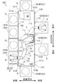
- FIG. 2 is a schematic plan view of the substrate processing equipment.
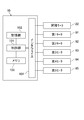
- FIG. 3 is a functional block diagram of the robot.
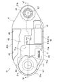
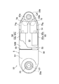
- FIG. 4 is a plan view of the first link in a state where a part of the first lid is broken.
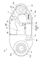
- FIG. 5 is a bottom view of the first link in a state where a part of the second lid is broken.
- FIG. 6 is a schematic cross-sectional view of the first link on the VI-VI line of FIG.
- FIG. 7 is a bottom view of the third link in a state where a part of the second lid is broken.
- FIG. 1 is a side view of the horizontal articulated robot 100.
- the horizontal articulated robot (hereinafter, also simply referred to as “robot”) 100 is a SCARA (SCARA: Selective Compliance Assembly Robot Arm) type robot.
- the robot 100 includes a base 1, an arm 3 rotatably connected to the base 1 in the horizontal direction, and a hand 8 rotatably connected to the arm 3 in the horizontal direction.
- the arm 3 is composed of a plurality of links 30 that are rotatably connected to each other in the horizontal direction.
- Hand 8 holds the object.
- the object is the substrate S.
- Hand 8 is an example of an end effector.
- FIG. 2 is a schematic plan view of the substrate processing equipment 120.
- the robot 100 is incorporated into, for example, a substrate transfer system 110 that conveys the substrate S.
- the board transfer system 110 includes a housing 111 and a robot 100.
- the substrate transfer system 110 is an EFEM (Equipment Front End Module).
- the substrate transfer system 110 conforms to the SEMI (Semiconductor Equipment and Materials International) standard.
- the configuration of the substrate transfer system 110 may be a configuration outside the SEMI standard.
- a transport space 112 is formed inside the housing 111.
- the robot 100 is arranged inside the housing 111, that is, in the transport space 112.
- the robot 100 transports the substrate S in the transport space 112.
- the substrate S is a disk-shaped semiconductor wafer.
- the front-rear direction, the left-right direction, and the up-down direction (that is, the vertical direction) that are orthogonal to each other are set.
- the housing 111 is formed in a substantially rectangular parallelepiped box shape.
- the housing 111 includes a front wall 111a and a rear wall 111b facing each other in the front-rear direction, a left wall 111c and a right wall 111d facing each other in the left-right direction, and a ceiling wall (not shown) and a bottom wall (not shown) facing each other in the vertical direction. ) And.
- the distance between the left wall 111c and the right wall 111d is larger than the distance between the front wall 111a and the rear wall 111b. That is, the housing 111 is formed in a substantially rectangular shape that is long in the left-right direction in a plan view.
- the transport space 112 is clean.
- the atmospheric gas that fills the transport space 112 is adjusted by a fan filter unit or the like.
- the transport space 112 is provided with an aligner 113 for aligning the substrate S.
- the substrate transfer system 110 is incorporated in the substrate processing equipment 120.
- the substrate processing equipment 120 includes a substrate transfer system 110 and a plurality of accommodating portions 121 for accommodating the substrate S.
- a storage chamber is formed inside the storage portion 121.
- the containment room is clean.
- the plurality of accommodating units 121 include a hoop (FOUP: Front Opening Unified Pod) 121A and a processing device 121B.
- the hoop 121A accommodates the substrate S.
- the processing device 121B processes the substrate S.
- the hoop 121A and the processing device 121B are arranged adjacent to the housing 111, respectively.
- the hoop 121A is an example of a container for accommodating a semiconductor wafer.
- the substrate S before and after the treatment is housed in the hoop 121A.
- the hoop 121A is a substrate container for mini-environment.
- the hoop 121A accommodates a plurality of substrates S in a horizontal state at equal intervals in the vertical direction.
- the hoop 121A is arranged outside the housing 111 and is attached to the front wall 111a via a hoop opener (not shown).
- a hoop opener not shown.
- four hoops 121A are provided.
- the four hoops 121A are arranged at equal intervals in the left-right direction.
- the front wall 111a is formed with an opening 111e corresponding to the hoop 121A.
- the hoop opener switches the communication and blocking between the transport space 112 and the internal space of the hoop 121A.
- the processing device 121B is a processing device that performs, for example, heat treatment, impurity introduction treatment, thin film formation treatment, lithography treatment, cleaning treatment, flattening treatment, or appearance or dimensional inspection on the substrate S.
- the processing performed by the processing device 121B may be temporary accommodation for delivering the substrate S.
- the rear wall 111b is provided with two processing devices 121B, the left wall 111c is provided with one processing device 121B, and the right wall 111d is provided with one processing device 121B.
- the processing device 121B is arranged outside the housing 111.
- An opening 111f corresponding to the processing device 121B is formed on each wall.
- a door (not shown) may be provided in the opening 111f. By opening and closing the door, communication and blocking between the transport space 112 and the internal space of the processing device 121B can be switched.
- the robot 100 included in the substrate transfer system 110 transfers the semiconductor wafer between the hoop 121A for accommodating the semiconductor wafer and the processing device 121B for processing the semiconductor wafer.
- the hand 8 holds the semiconductor wafer as the substrate S.
- the arm 3 and the hand 8 convey the semiconductor wafer between the hoop 121A and the processing device 121B.
- the base 1 has a housing 11 and an elevating mechanism 2 for elevating and lowering the arm 3 in the vertical direction.
- the housing 11 is formed in a substantially rectangular parallelepiped shape.
- the elevating mechanism 2 has a movable portion 21 and an elevating motor 22 for driving the movable portion 21.
- the movable portion 21 is formed in a columnar shape. In the state where the movable portion 21 is most lowered, most of the movable portion 21 is housed in the housing 11. The movable portion 21 rises so as to project upward from the housing 11.
- the arm 3 is rotatably connected to the upper end of the movable portion 21 in the horizontal direction. As shown by the solid line and the alternate long and short dash line in FIG. 1, the movable portion 21 moves up and down, and the arm 3 and the hand 8 move up and down accordingly.
- the arm 3 is composed of three links 30.
- the three links 30 are distinguished from each other, they are referred to as a first link 31, a second link 32, and a third link 33 in order from the one closest to the base 1.
- the first link 31 is a link 30 connected to the base 1.
- a hand 8 is connected to the third link 33.
- the link 30 is formed in a shape extending in a predetermined longitudinal direction.
- first end one end in the longitudinal direction
- second end the end opposite to the first end in the longitudinal direction
- the "width direction" of the link 30 means a direction orthogonal to both the vertical direction and the longitudinal direction of the link 30.
- the first end 31a of the first link 31 is rotatably connected to the base 1 about the first axial center L1 extending in the vertical direction. Specifically, the first end portion 31a is connected to the upper end portion of the movable portion 21.
- the first end portion 32a of the second link 32 is rotatably connected to the second end portion 31b of the first link 31 about the second axial center L2 extending in the vertical direction.
- the first end 33a of the third link 33 is rotatably connected to the second end 32b of the second link 32 about the third axial center L3 extending in the vertical direction.
- the first axis L1, the second axis L2, and the third axis L3 extend in parallel with each other.
- the length of the first link 31 (that is, the dimension in the longitudinal direction) is the longest of the three links 30.
- the robot 100 has two hands 8, that is, a first hand 8A and a second hand 8B.
- first hand 8A and the second hand 8B are simply referred to as "hand 8".
- the basic configurations of the first hand 8A and the second hand 8B are the same. In FIG. 2, since the two hands 8 are vertically overlapped with each other, only one hand 8 is apparently shown.
- Holding by the hand 8 can be realized in various modes such as gripping, suction, mounting or fitting.
- the hand 8 has a main body 81 and a holding portion 82 connected to the main body 81 and divided into two branches.
- the hand 8 is formed in a plate shape.
- the hand 8 is formed in a substantially Y shape when viewed in the thickness direction thereof.
- the hand 8 has a holding actuator (not shown) such as an air cylinder. The holding actuator switches between holding and releasing the object by the hand 8.
- the main body 81 of each hand 8 is rotatably connected to the second end 33b of the third link 33 about the fourth axis L4 extending in the vertical direction.
- the fourth axis L4 extends in parallel with the first axis L1, the second axis L2, and the third axis L3.
- the first link 31, the second link 32, the third link 33, the first hand 8A, and the second hand 8B are stacked in this order from bottom to top without contacting each other.
- the first link 31, the second link 32, the third link 33, and the two hands 8 rotate in the horizontal direction without interfering with each other.
- Robot 100 is equipped with various parts.
- the parts include parts related to driving the arm 3 and the hand 8 (hereinafter referred to as “arm 3 and the like”), parts related to detecting the operation of the arm 3 and the like, and the like.
- Parts related to driving such as the arm 3 include a plurality of motors 6 for rotationally driving a plurality of links 30 and a hand 8, a transmission mechanism corresponding to each motor 6, and a holding for executing holding and releasing of an object by the hand 8.
- Parts and the like related to the actuator are included.
- Parts related to the holding actuator include, for example, when the holding actuator is an air cylinder, a pipe for supplying air to the air cylinder, an electromagnetic valve for switching the supply of air, and the like.
- the pressure in the pipe provided in the pipe for sucking air from the suction part of the hand 8 when the hand 8 holds the object by suction is detected.
- the parts related to the drive of the arm 3 and the like and the parts related to the detection of the operation of the arm 3 and the like include harnesses and pipes.
- the plurality of motors 6 include a first motor 61 that rotationally drives the first link 31, a second motor 62 that rotationally drives the second link 32, and a third motor 63 that rotationally drives the third link 33. It includes a fourth motor 64 that rotationally drives the one hand 8A, and a fifth motor 65 that rotationally drives the second hand 8B.
- a first motor 61 that rotationally drives the first link 31
- a second motor 62 that rotationally drives the second link 32
- a third motor 63 that rotationally drives the third link 33.
- It includes a fourth motor 64 that rotationally drives the one hand 8A, and a fifth motor 65 that rotationally drives the second hand 8B.
- the link 30 is formed in a hollow shape and has an internal space.
- the internal space of the link 30 is a storage chamber for accommodating parts.
- the motor 6 is housed in the internal space of the link 30.
- the first motor 61 and the second motor 62 are housed in the internal space of the first link 31.
- the third motor 63 is housed in the internal space of the second link 32.
- the fourth motor 64 and the fifth motor 65 are housed in the internal space of the third link 33.
- the base 1 of the robot 100 is arranged offset from the center of the housing 111 to one of the front wall 111a and the rear wall 111b in the front-rear direction. Specifically, the base 1 is arranged closer to the rear wall 111b than to the front wall 111a. In the left-right direction, the base 1 is arranged substantially in the center of the housing 111. In this way, by arranging the base 1 offset from the center of the housing 111 to one of the front wall 111a and the rear wall 111b in the front-rear direction, the length of each link 30 is lengthened. The movable range of the hand 8 is expanded.
- FIG. 3 is a functional block diagram of the robot 100.
- the robot 100 further includes a control device 10.
- the control device 10 includes a control unit 101 that performs overall control of the robot 100, a storage unit 102 that stores various programs and various data, a memory 103, and an interface 104 that is connected to a motor 6 or the like. ing.
- the storage unit 102 is a recording medium that can be read by a computer, and is composed of, for example, a flash memory.
- the storage unit 102 may be composed of an optical disk such as a CD-ROM.
- the storage unit 102 stores various programs and various data necessary for executing the processing of the control unit 101.
- the control unit 101 controls the motor 6 and the like based on the program stored in the storage unit 102.
- the control unit 101 is composed of a processor such as a CPU (Central Processing Unit), for example.
- the control unit 101 executes various processes by expanding the program stored in the storage unit 102 or the like into the memory 103 and executing the program.
- the control unit 101 may be realized by hardware such as an LSI (Large Scale Integration) having the same function as the processor.
- An elevating motor 22, a first motor 61, a second motor 62, a third motor 63, a fourth motor 64, and a fifth motor 65 are connected to the interface 104. Further, depending on the mode of the end effector, an actuator for operating the end effector (in the case of the hand 8, a holding actuator) is also connected to the interface 104.
- the control device 10 controls the motor 6 and the like in accordance with a predetermined operation program or an operation command input from the user to control the robot 100.
- the control device 10 displaces the arm 3 and causes the hand 8 to hold or release the substrate S.
- the control device 10 displaces the arm 3 and the hand 8 to allow the hand 8 to enter the internal space of the hoop 121A (see the solid line in FIG. 2). Then, the control device 10 causes the hand 8 to hold the substrate S in the hoop 121A. The control device 10 causes the hand 8 holding the substrate S to exit from the hoop 121A to the transport space 112 and further to enter the processing device 121B (see the alternate long and short dash line in FIG. 2). The control device 10 causes the hand 8 to release the substrate S at a predetermined position in the processing device 121B. After that, the control device 10 temporarily ejects the hand 8 from the processing device 121B.
- the control device 10 causes the hand 8 to enter the processing device 121B and causes the hand 8 to hold the substrate S.
- the control device 10 causes the hand 8 holding the substrate S to exit from the processing device 121B into the transport space 112, and further enters the hoop 121A.
- the control device 10 causes the hand 8 to release the substrate S at a predetermined position of the hoop 121A. In this way, the control device 10 causes the robot 100 to convey the substrate S between the hoop 121A and the processing device 121B.
- FIG. 4 is a plan view of the first link 31 in a state where a part of the first lid 42A is broken.
- FIG. 5 is a bottom view of the first link 31 in a state where a part of the second lid 42B is broken.
- FIG. 6 is a schematic cross-sectional view of the first link 31 on the VI-VI line of FIG.
- the number of motors 6 accommodated in the first link 31 is two.
- An internal space 40 is formed in the first link 31 so as to accommodate various parts.
- the first link 31 has a partition wall 45 that partitions the internal space 40 into two storage chambers in which the parts are housed.
- the two accommodation chambers are a first accommodation chamber 40A in which the first motor 61 is accommodated and a second accommodation chamber 40B in which the second motor 62 is accommodated.
- the first link 31 has a housing 4 that partitions the outer shape of the first link 31.
- An internal space 40 is formed inside the housing 4.
- the housing 4 has a housing main body 41 and a first lid 42A and a second lid 42B attached to the housing main body 41.
- the housing body 41 partitions at least a part of the internal space 40, and has a ceiling wall 43 and a bottom wall 44 separated in the vertical direction.
- the housing body 41 further partitions the outer shape of the first link 31 in a plan view, and further has an outer peripheral wall 46 formed in an annular shape.
- the outer peripheral wall 46 extends in an annular shape along the outer shape of the first link 31 in a plan view, that is, the contour.
- the outer peripheral wall 46 has a width (that is, a height) in the vertical direction and extends in the vertical direction as well.
- the ceiling wall 43 is connected to the upper end of the outer peripheral wall 46 so as to close a part of the opening at the upper end of the outer peripheral wall 46 including the second end portion 31b of the first link 31.
- the bottom wall 44 is connected to the lower end of the outer peripheral wall 46 so as to close a part of the opening at the lower end of the outer peripheral wall 46 including the first end portion 31a of the first link 31.
- the ceiling wall 43 and the bottom wall 44 are arranged so as to be aligned in the longitudinal direction of the first link 31 in a plan view.
- the partition wall 45 extends from the ceiling wall 43 to the bottom wall 44 across the internal space 40. That is, the partition wall 45 vertically crosses the internal space 40.
- the upper end of the partition wall 45 is connected to the ceiling wall 43.
- the lower end of the partition wall 45 is connected to the bottom wall 44.
- the partition wall 45 extends across the inside of the outer peripheral wall 46 and is connected to at least two places of the outer peripheral wall 46. At this time, the partition wall 45 extends across the internal space 40 so as to be generally inclined with respect to the longitudinal direction of the first link 31 in a plan view. More specifically, the partition wall 45 is formed in a zigzag shape in a plan view.
- the partition wall 45 has a bent portion 45c formed by a vertical portion 45a extending in the longitudinal direction of the first link 31 and a horizontal portion 45b extending in the width direction of the first link 31.
- the partition wall 45 is formed so that the vertical portion 45a and the horizontal portion 45b are alternately connected. That is, the partition wall 45 has a plurality of bent portions 45c.
- the partition wall 45 is integrally formed with the ceiling wall 43 and the bottom wall 44. Specifically, the ceiling wall 43, the bottom wall 44, and the partition wall 45 are formed of a single member.
- the outer peripheral wall 46 is also integrally formed with the ceiling wall 43, the bottom wall 44, and the partition wall 45. Specifically, the ceiling wall 43, the bottom wall 44, the partition wall 45, and the outer peripheral wall 46 are formed of a single member. That is, the partition wall 45 is formed of a housing body 41 and a single member. For example, the housing body 41 is formed by carving out metal as a single member. At this time, the partition wall 45 is integrally machined with the housing body 41 as a part of the housing body 41. In other words, the ceiling wall 43, the bottom wall 44, the partition wall 45, and the outer peripheral wall 46 are joined to each other without any seams such as welding.
- the housing body 41 configured in this way is formed so that the first storage chamber 40A opens upward and the second storage chamber 40B opens downward.
- the first accommodation chamber 40A is formed in a portion closer to the first end portion 31a including the first end portion 31a
- the second accommodation chamber 40B is the second end including the second end portion 31b. It is formed in a portion closer to the portion 31b.
- the bottom wall 44 partitions the lower part of the first storage chamber 40A.
- the first accommodation chamber 40A is partitioned by an outer peripheral wall 46, a bottom wall 44, and a partition wall 45.
- the first lid 42A is attached to the upper end edge of the outer peripheral wall 46 by screws 49. The first lid 42A closes the first containment chamber 40A.
- the ceiling wall 43 partitions the upper part of the second storage chamber 40B.
- the second accommodation chamber 40B is partitioned by an outer peripheral wall 46, a ceiling wall 43, and a partition wall 45.
- the second lid 42B is attached to the lower end edge of the outer peripheral wall 46 by a screw 49.
- the second storage chamber 40B is closed by the second lid 42B.
- the first accommodation chamber 40A a part of the movable portion 21 extending from the base 1 is arranged. Specifically, the upper end of the movable portion 21 is formed by the first shaft 21a. An insertion hole 44a through which the first shaft 21a penetrates is formed in the bottom wall 44 at the first end portion 31a. The first shaft 21a cannot rotate with respect to the base 1. The first shaft 21a penetrates the insertion hole 44a and enters the first storage chamber 40A.
- the first shaft 21a is rotatably supported by a bearing 48a arranged in the first accommodation chamber 40A. The axial center of the first shaft 21a coincides with the first axial center L1.
- the bearing 48a is fixed to the housing body 41. As a result, the housing body 41 can rotate relative to the first shaft 21a via the bearing 48a. That is, the first link 31 is rotatable relative to the base 1.
- the first storage chamber 40A houses the first motor 61 and the first transmission mechanism 71 that transmits the power of the first motor 61.
- the first motor 61 has a motor body 61a fixed to the housing body 41 and a rotating shaft 61b extending from the motor body 61a.
- the first motor 61 is an electric motor, specifically a servomotor.
- the first motor 61 has an encoder (not shown) that detects the rotation position or the amount of rotation of the rotation shaft 61b.
- the first motor 61 is arranged in the first accommodation chamber 40A in a state where the rotating shaft 61b extends in the horizontal direction (specifically, the longitudinal direction of the first link 31).
- the first transmission mechanism 71 transmits the power of the first motor 61 to the first shaft 21a.
- the first transmission mechanism 71 has a gear train.
- the gear train consists of a first gear 71a coaxially attached to the rotating shaft 61b, a second gear 71b in which the rotation of the first gear 71a is transmitted via one or a plurality of gears (not shown), and a second gear.
- the third gear 71c that rotates integrally with the 71b, the fourth gear 71d that meshes with the third gear 71c, the fifth gear 71e that rotates integrally with the fourth gear 71d, and the fifth gear 71e that mesh with the first gear 71e.
- It includes a sixth gear 71f coaxially attached to the shaft 21a.
- the second gear 71b and the third gear 71c rotate integrally around an axial center extending in the horizontal direction.
- the third gear 71c and the fourth gear 71d are bevel gears.
- the fourth gear 71d and the fifth gear 71e rotate integrally around the axis extending parallel to the first axis L1.
- the first gear 71a, the second gear 71b, the third gear 71c, the fourth gear 71d, and the fifth gear 71e are housed in the gearbox 71g.
- the gearbox 71g is arranged in the first storage chamber 40A.
- the rotation of the rotating shaft 61b is transmitted to the first shaft 21a via a gear train such as the first gear 71a. Since the first shaft 21a cannot rotate, the housing 4 to which the first motor 61 is fixed rotates around the first axis L1. As a result, the first link 31 rotates about the first axis L1 relative to the base 1.
- a part of the second shaft 34 extending from the second link 32 is arranged in the second storage chamber 40B.
- the ceiling wall 43 at the second end 31b is formed with an insertion hole 43a through which the second shaft 34 penetrates.
- the second shaft 34 is non-rotatably attached to the second link 32.
- the tip of the second shaft 34 penetrates the insertion hole 43a and enters the second storage chamber 40B.
- the second shaft 34 is rotatably supported by a bearing 48b arranged in the second accommodation chamber 40B.
- the axis of the second shaft 34 coincides with the second axis L2.
- the bearing 48b is fixed to the housing body 41. As a result, the second shaft 34 can rotate relative to the housing body 41 via the bearing 48b. That is, the second link 32 is rotatable relative to the first link 31.
- the second storage chamber 40B houses the second motor 62 and the second transmission mechanism 72 that transmits the power of the second motor 62.
- the second motor 62 has a motor body 62a fixed to the housing body 41 and a rotating shaft 62b extending from the motor body 62a.
- the second motor 62 is an electric motor, specifically a servomotor.
- the second motor 62 has an encoder (not shown) that detects the rotation position or the amount of rotation of the rotation shaft 62b.
- the second motor 62 is arranged in the second accommodation chamber 40B in a state where the rotating shaft 62b extends in the horizontal direction (specifically, the longitudinal direction of the first link 31).
- the second transmission mechanism 72 transmits the power of the second motor 62 to the second shaft 34.
- the second transmission mechanism 72 has a gear train.
- the gear train consists of a first gear 72a coaxially attached to the rotating shaft 62b, a second gear 72b in which the rotation of the first gear 72a is transmitted via one or a plurality of gears (not shown), and a second gear.
- the third gear 72c that rotates integrally with the 72b, the fourth gear 72d that meshes with the third gear 72c, the fifth gear 72e that rotates integrally with the fourth gear 72d, and the fifth gear 72e that meshes with the fifth gear 72e.
- the second gear 72b and the third gear 72c rotate integrally around an axial center extending in the horizontal direction.
- the third gear 72c and the fourth gear 72d are bevel gears.
- the fourth gear 72d and the fifth gear 72e rotate integrally around the axis extending parallel to the second axis L2.
- the first gear 72a, the second gear 72b, the third gear 72c, the fourth gear 72d, and the fifth gear 72e are housed in the gear box 72g.
- the gearbox 72g is arranged in the second storage chamber 40B.
- the second motor 62 When the second motor 62 operates, the rotation of the rotating shaft 62b is transmitted to the second shaft 34 via a gear train such as the first gear 72a. Since the second motor 62 is fixed to the housing 4, the second shaft 34 rotates around the second axis L2. As a result, the second link 32 rotates about the second axis L2 relative to the first link 31.
- the first accommodation chamber 40A and the second accommodation chamber 40B are opened in opposite directions in the direction of the first axis L1 or the second axis L2 (that is, in the vertical direction). Specifically, the first accommodation chamber 40A opens to the ceiling wall 43 side, and the second accommodation chamber 40B opens to the bottom wall 44 side.
- the first motor 61 and the gearbox 71g are installed in the first accommodation chamber 40A, the user accesses the inside of the first accommodation chamber 40A from the ceiling wall 43 side.
- the second motor 62 and the gearbox 72g are installed in the second accommodation chamber 40B, the user accesses the inside of the second accommodation chamber 40B from the bottom wall 44 side.
- the number of motors 6 accommodated in the second link 32 is one. Since the second link 32 does not need to accommodate the two motors 6, the width of the second link 32 is smaller than the width of the first link 31.
- the internal space of the second link 32 accommodates a third motor 63 and a third transmission mechanism (not shown) that transmits the power of the third motor 63.
- the third motor 63 and the third transmission mechanism have the same configuration and arrangement as the second motor 62 and the second transmission mechanism 72. That is, a part of the third shaft 35 (see FIG. 7) extending from the third link 33 is arranged in the portion of the internal space of the second link 32 corresponding to the second end portion 32b.
- the third shaft 35 extends coaxially with the third axis L3.
- the third transmission mechanism transmits the power of the third motor 63 to the third shaft.
- the third motor 63 When the third motor 63 operates, the rotation of the third motor 63 is transmitted to the third shaft 35 via the gear train. Since the third motor 63 is fixed to the housing of the second link 32, the third shaft 35 rotates around the third axis L3. As a result, the third link 33 rotates about the third axis L3 relative to the second link 32.
- FIG. 7 is a bottom view of the third link 33 in a state where a part of the second lid 52B is broken.
- the number of motors 6 accommodated in the third link 33 is two.
- the third link 33 is formed with an internal space 50 that accommodates the fourth motor 64 and the fifth motor 65.
- the third link 33 has a housing 5 that partitions the outer shape of the third link 33.
- An internal space 50 is formed inside the housing 5.
- the housing 5 has a housing main body 51, and a first lid (not shown) and a second lid 52B attached to the housing main body 51.
- the housing body 51 has a ceiling wall 53, a bottom wall 54, and an outer peripheral wall 56 that partition at least a part of the internal space 50.
- the outer peripheral wall 56 extends in an annular shape along the outer shape of the third link 33 in a plan view, that is, the contour.
- the outer peripheral wall 56 has a width (that is, a height) in the vertical direction and extends in the vertical direction as well.
- the bottom wall 54 is connected to the lower end of the outer peripheral wall 56 so as to close a part of the opening at the lower end of the outer peripheral wall 56 including the first end 33a of the third link 33.
- the ceiling wall 53 is connected to the upper end of the outer peripheral wall 56 so as to close a part of the opening at the upper end of the outer peripheral wall 56 including the second end 33b of the third link 33.
- the ceiling wall 53, the bottom wall 54, and the outer peripheral wall 56 are formed of a single member.
- the housing body 51 is formed by carving out metal as a single member.
- the ceiling wall 53, the bottom wall 54, and the outer peripheral wall 56 are joined to each other without any seams such as welding.
- the portion closer to the first end 33a, including the first end 33a, is open upward.
- the portion closer to the second end 33b including the second end 33b is open downward.
- the first lid is attached to the upper end edge of the outer peripheral wall 56 with screws. The first lid closes the portion of the internal space 50 that opens upward.
- the second lid 52B is attached to the lower end edge of the outer peripheral wall 56 by the screw 59. The second lid 52B closes the portion of the internal space 50 that opens downward.
- the portion of the internal space 50 that opens upward and the portion that opens downward are not partitioned by a wall such as the partition wall 45 of the first link 31.
- a third shaft 35 is non-rotatably attached to the bottom wall 54.
- the third shaft 35 extends coaxially with the third axis L3.
- One end of the third shaft 35 is arranged in the internal space 50, and the other end of the third shaft 35 (not shown) enters the internal space of the second link 32.
- a part of the shaft extending from the hand 8 is arranged in the internal space 50.
- a cylindrical fourth shaft 83a is non-rotatably connected to the main body 81 of the first hand 8A.
- the fourth shaft 83a extends coaxially with the fourth axis L4.
- a cylindrical fifth shaft 83b is non-rotatably connected to the main body 81 of the second hand 8B.
- the fifth shaft 83b passes through the inside of the fourth shaft 83a and extends coaxially with the fourth axis L4.
- the fourth shaft 83a and the fifth shaft 83b are rotatably supported by a plurality of bearings arranged in the internal space 50, respectively. The bearing is fixed to the housing body 51.
- the first hand 8A and the second hand 8B can rotate relative to the housing body 51 via the bearing. That is, the first hand 8A and the second hand 8B can rotate relative to the third link 33. The first hand 8A and the second hand 8B can rotate independently of each other.
- a fourth motor 64 In the internal space 50, a fourth motor 64, a fourth transmission mechanism 74 that transmits the power of the fourth motor 64, a fifth motor 65, and a fifth transmission mechanism 75 that transmits the power of the fifth motor 65 are provided. It is contained.
- the fourth motor 64 has a motor body 64a fixed to the housing body 51 and a rotating shaft 64b extending from the motor body 64a.
- the fourth motor 64 is an electric motor, specifically a servomotor.
- the fourth motor 64 has an encoder (not shown) that detects the rotation position or the amount of rotation of the rotation shaft 64b.
- the fourth motor 64 is arranged in the internal space 50 in a state where the rotating shaft 64b extends in the horizontal direction (specifically, the longitudinal direction of the third link 33).
- the fourth transmission mechanism 74 transmits the power of the fourth motor 64 to the fourth shaft 83a.
- the fourth transmission mechanism 74 has a gear train. Although not shown, the gear train transmits the rotation of the first gear coaxially attached to the rotating shaft 64b, the sixth gear coaxially attached to the fourth shaft 83a, and the rotation of the first gear to the sixth gear. Includes multiple intermediate gears.
- the gear train is housed in a gearbox 74g.
- the gearbox 74g is arranged in the internal space 50.
- the fourth motor 64 When the fourth motor 64 operates, the rotation of the rotating shaft 64b is transmitted to the fourth shaft 83a via the gear train. Since the fourth motor 64 is fixed to the housing 5, the fourth shaft 83a rotates around the fourth axis L4. As a result, the first hand 8A rotates about the fourth axis L4 relative to the third link 33.
- the fifth motor 65 has a motor body 65a fixed to the housing body 51 and a rotating shaft 65b extending from the motor body 65a.
- the fifth motor 65 is an electric motor, specifically a servomotor.
- the fifth motor 65 has an encoder (not shown) that detects the rotation position or the rotation amount of the rotation shaft 65b.
- the fifth motor 65 is arranged in the internal space 50 in a state where the rotating shaft 65b extends in the horizontal direction (specifically, the longitudinal direction of the third link 33).
- the fifth transmission mechanism 75 transmits the power of the fifth motor 65 to the fifth shaft 83b.
- the fifth transmission mechanism 75 has a gear train. Although not shown, the gear train transmits the rotation of the first gear coaxially attached to the rotating shaft 65b, the sixth gear coaxially attached to the fifth shaft 83b, and the rotation of the first gear to the sixth gear. Includes multiple intermediate gears.
- the gear train is housed in a gear box 75 g.
- the gearbox 75g is arranged in the internal space 50.
- the rotation of the rotating shaft 65b is transmitted to the fifth shaft 83b via the gear train. Since the fifth motor 65 is fixed to the housing 5, the fifth shaft 83b rotates around the fourth axis L4. As a result, the second hand 8B rotates about the fourth axis L4 relative to the third link 33.
- a third link 33 two motors 6 are housed in an unpartitioned internal space 50.
- the fourth motor 64 and the fifth motor 65 are arranged side by side in the width direction of the third link 33.
- the fourth transmission mechanism 74 and the fifth transmission mechanism 75 are arranged side by side in the width direction of the third link 33.
- the arm 3 configured in this way is cantileveredly connected to the base 1 and is rotationally displaced and deformed. Therefore, the weight and inertial force of the arm 3 act on each link 30. Since the first link 31 has a partition wall 45 that partitions the internal space 40 between the first storage chamber 40A and the second storage chamber 40B, the rigidity of the first link 31 (as compared with the configuration without the partition wall 45) Specifically, the bending rigidity or the torsional rigidity) becomes high. As a result, the position accuracy of the arm 3 and, by extension, the position accuracy of the hand 8 can be improved.
- the weight of the first link 31 becomes large.
- the first link 31 is the link 30 closest to the base 1 among the plurality of links 30, the weights of the other links 30 and the hand 8 also act on the first link 31.
- the first link 31 is the longest of the three links 30, it is easy to bend. Therefore, increasing the rigidity of the first link 31 is effective for the rigidity of the entire arm 3.
- the partition wall 45 is connected to the ceiling wall 43 and the bottom wall 44 as shown in FIGS. 4 to 6.
- the ceiling wall 43, the bottom wall 44, and the partition wall 45 have a shape that is bent like a crank as a whole.
- the partition wall 45 is arranged so as to cross the inside of the annular outer peripheral wall 46, and is connected to two places of the outer peripheral wall 46.
- the flexural rigidity and / or the torsional rigidity of the outer peripheral wall 46 is improved, and as a result, the rigidity of the first link 31 is further improved.
- the partition wall 45 extends so as to be generally inclined with respect to the width direction of the first link 31 in a plan view. That is, the region where the partition wall 45 exists becomes longer in the longitudinal direction of the first link 31. As a result, the portion whose rigidity is reinforced by the partition wall 45 can be expanded in the longitudinal direction of the first link 31. As a result, the rigidity of the first link 31 is further improved.
- the partition wall 45 has a bent portion 45c. Thereby, the rigidity of the partition wall 45 can be improved. Further, since the partition wall 45 has a plurality of bent portions 45c, the rigidity of the partition wall 45 is further improved. As a result, the rigidity of the first link 31 is further improved.
- the partition wall 45 is inclined as a whole with respect to the width direction of the first link 31 in a plan view, so that the partition wall 45 extends in the width direction of the first link 31.
- Each of the first accommodation chamber 40A and the second accommodation chamber 40B becomes a long space in the longitudinal direction of the first link 31.
- the occupied space of the first shaft 21a, the gearbox 71g and the first motor 61 is the entire space. It tends to be elongated. Therefore, by making the first accommodation chamber 40A a long space in the longitudinal direction of the first link 31, the internal space 40 of the first link 31 can be effectively utilized to effectively utilize the first shaft 21a, the gearbox 71g, and the first motor. 61 can be arranged.
- the second shaft 34 and the gearbox 72g are adjacent to each other and the gearbox 72g and the second motor 62 are arranged adjacent to each other, the second shaft 34, the gearbox 72g, and the second motor 62 are occupied.
- the space tends to be elongated overall. Therefore, by making the second accommodation chamber 40B a long space in the longitudinal direction of the first link 31, the internal space 40 of the first link 31 is effectively utilized, and the second shaft 34, the gearbox 72 g, and the second motor are used. 62 can be placed.
- the robot 100 includes a base 1, an arm 3 composed of a plurality of links 30 rotatably connected to the base 1 in the horizontal direction and rotatably connected to each other in the horizontal direction.
- An internal space 40 is formed in the first link 31, which is at least one of the plurality of links 30 and includes a hand 8 (end effector) rotatably connected to the arm 3 in the horizontal direction.
- Reference numeral 31 denotes a partition wall 45 for partitioning the internal space 40 into two storage chambers, that is, a first storage chamber 40A and a second storage chamber 40B, respectively, in which parts are housed.
- the partition wall 45 improves the rigidity of the first link 31.
- the first link 31 has an internal space 40 for accommodating parts and is formed in a hollow shape.
- the interior space 40 is partitioned by a partition wall 45 into two storage chambers for storing parts, that is, a first storage chamber 40A and a second storage chamber 40B.
- partitioning the internal space 40 into the first storage chamber 40A and the second storage chamber 40B it becomes easy to store various parts in an orderly manner. That is, as compared with the case where various parts are housed in a single space, the various parts can be divided into a plurality of storage chambers, that is, can be arranged and stored.
- the partition wall 45 functions as a strength member in the hollow first link 31.
- the rigidity of the first link 31, that is, the flexural rigidity or the torsional rigidity can be improved as compared with the configuration having no partition wall 45.
- the parts include a plurality of motors 6 for rotationally driving the plurality of links 30 and the hand 8, and each of the first accommodation chamber 40A and the second accommodation chamber 40B has a motor 6 of one of the plurality of motors 6. Contain.
- the first accommodation chamber 40A accommodates the first motor 61
- the second accommodation chamber 40B accommodates the second motor 62.
- the first link 31 accommodates two motors 6, the total weight of the first link 31 becomes large. Therefore, it is very effective to provide the partition wall 45 on the first link 31 to improve the rigidity.
- first link 31 partitions at least a part of the internal space 40 and has a ceiling wall 43 and a bottom wall 44 separated in the vertical direction, and the partition wall 45 extends from the ceiling wall 43 to the bottom wall 44. There is.
- the ceiling wall 43 and the bottom wall 44 are connected by the partition wall 45.
- the rigidity of the ceiling wall 43, the bottom wall 44, and the partition wall 45 as a whole is improved.
- the rigidity of the first link 31 is improved.
- the bottom wall 44 partitions the lower part of the first storage chamber 40A, which is one of the two storage chambers, the first storage chamber 40A is formed so as to open upward, and the ceiling wall 43 is formed.
- the upper part of the second containment chamber 40B which is the other containment chamber of the two containment chambers, is partitioned, and the second containment chamber 40B is formed so as to open downward.
- one containment chamber opens upward and the other containment chamber opens downward.
- the partition wall 45 extending from the ceiling wall 43 to the bottom wall 44, it is easy to realize a storage chamber having such a configuration.
- the first link 31 has a housing 4 for partitioning the outer shape of the first link 31, the housing 4 has a housing body 41 on which a ceiling wall 43 and a bottom wall 44 are formed, and the partition wall 45 has a partition wall 45. It is formed of a housing body 41 and a single member.
- the housing body 41 and the partition wall 45 are formed of a single member, the housing body 41 and the partition wall 45 are compared with the configuration in which the partition wall 45 is attached to the housing body 41.
- the bond becomes stronger.
- the rigidity of the first link 31 is further improved.
- the first link 31 partitions the outer shape of the first link 31 in a plan view and has an outer peripheral wall 46 formed in an annular shape, and the partition wall 45 extends across the inside of the outer peripheral wall 46 and is formed on the outer peripheral wall 46. It is connected in at least two places.
- the partition wall 45 improves the rigidity of the outer peripheral wall 46. As a result, the rigidity of the first link 31 is further improved.
- the partition wall 45 has a bent portion 45c formed so as to bend.
- the rigidity of the partition wall 45 is improved as compared with the case where the partition wall 45 is formed flat. Since the rigidity of the partition wall 45 itself is improved, the rigidity of the first link 31 is further improved.
- the plurality of links 30 are three links 30.
- the position accuracy of the end effector tends to decrease as compared with the arm formed by one or two links.
- the rigidity of the first link 31, which is one of the three links 30 the position accuracy of the end effector can be improved. That is, in the arm 3 composed of the three links 30, it is particularly effective to improve the rigidity of the arm 3 by the partition wall 45.
- first link 31 is a link connected to the base 1 among the plurality of links 30.
- the weights of the other links 30 and the hand 8 also act on the first link 31. Therefore, increasing the rigidity of the first link 31 is effective in improving the rigidity of the entire arm 3.
- the hand 8 is an example of an end effector and holds the substrate S.
- the robot 100 conveys the substrate S.
- the position accuracy of the substrate S can be improved.
- the hand 8 holds the semiconductor wafer as the substrate S, and the arm 3 and the hand 8 convey the semiconductor wafer between the hoop 121A, which is a container for accommodating the semiconductor wafer, and the processing device 121B for processing the semiconductor wafer.
- the robot 100 conveys the semiconductor wafer between the hoop 121A and the processing device 121B. Since the semiconductor wafer is delicate and the processing of the semiconductor wafer is fine, high position accuracy is required in the transfer of the semiconductor wafer. Therefore, it is particularly effective to improve the rigidity of the arm 3.
- the substrate transfer system 110 includes a housing 111 and a robot 100 arranged in the housing 111.
- the robot 100 includes a hoop 121A arranged adjacent to the housing 111 and accommodating the substrate S, and a housing.
- the substrate S is conveyed to and from the processing device 121B which is arranged adjacent to the 111 and processes the substrate S.
- the robot 100 is incorporated in the substrate transfer system 110 that conveys the substrate S between the hoop 121A and the processing device 121B. Since the robot 100 has a high rigidity of the arm 3, the substrate transfer system 110 can transfer the substrate S with high position accuracy.
- the robot 100 is incorporated in the substrate transfer system 110, but is not limited thereto.
- the robot 100 is not limited to use in a clean environment capable of processing semiconductors.
- the robot 100 may be incorporated in a production line or the like.
- the board transfer system 110 does not have to be incorporated in the board processing equipment 120. That is, the substrate transfer system 110 may adopt any configuration as long as the robot 100 conveys the substrate S in the housing 111.
- the moving source and moving destination of the substrate S are not limited to the hoop 121A and the processing device 121B.
- the number of divisions of the arm 3, that is, the number of links 30, is not limited to 3.
- the arm 3 may be composed of two or four or more links 30.
- the end effector is not limited to hand 8.
- the end effector may be a painting tool or a welding tool. Even when the end effector is the hand 8, the object held by the hand 8 is not limited to the substrate.
- the number of hands 8 (that is, the number of end effectors) is not limited to two, and may be one or three or more.
- the robot 100 has the same number of motors 6 as the total of the links 30 and the hands 8, but the number of motors 6 does not have to be the same as the total of the links 30 and the hands 8.
- one motor 6 may rotationally drive two links 30.
- the link 30 accommodating the two motors 6 and having the partition wall 45 may be a link 30 other than the first link 31.
- the second link 32 or the third link 33 may have a partition wall and accommodate two motors 6.
- the third link 33 may have a partition wall.
- the housing main body 51 may have a partition wall that partitions the internal space 50 between the storage chamber in which the fourth motor 64 is housed and the storage room in which the fifth motor 65 is housed.
- a partition wall can be provided so as to extend in the longitudinal direction of the third link 33 at the center in the width direction of the third link 33. This partition wall may be connected to the ceiling wall 53.
- the motor 6 accommodated in the two accommodation chambers partitioned by the partition wall is not limited to the first motor 61 and the second motor 62, and may be any two of the plurality of motors 6. good.
- the parts housed in the two storage chambers are not limited to the motor 6.
- Parts related to driving the arm 3 and the like such as a harness and parts related to detecting the operation of the arm 3 and the like may be housed in the respective storage chambers.
- the partition wall any configuration can be adopted for the partition wall as long as it separates the two containment chambers.
- the two containment chambers separated by a partition wall may partially communicate. That is, the two containment chambers do not have to be completely isolated.
- the partition wall 45 may be connected to at least one of the ceiling wall 43, the bottom wall 44, and the outer peripheral wall 46.
- the partition wall 45 may be connected only to the bottom wall 44 and not to the ceiling wall 43 and the outer peripheral wall 46.
- the partition wall 45 improves the rigidity of the bottom wall 44, and as a result, improves the rigidity of the first link 31.
- the partition wall 45 may not be connected to the ceiling wall 43 and the bottom wall 44, but may be connected to the outer peripheral wall 46.
- the partition wall 45 may partition the internal space 40 into at least two storage chambers, and may partition the internal space 40 into three or more spaces including the two storage chambers.
- partition wall 45 may have a flat shape without having a bent portion 45c.
- the partition wall 45 may extend in the longitudinal direction or the width direction of the link 30.
- the partition wall 45 may be formed separately from the housing main body 41 and may be connected to the housing main body 41 by welding, screw fastening, or the like. Even with such a configuration, the partition wall 45 improves the rigidity of the housing body 41.
- the formation of the housing body 41 including the partition wall 45 with a single member is not limited to cutting.
- the housing body 41 may be formed by casting.
- the substrate S can be a thin plate that is a material for a substrate of a semiconductor device such as a semiconductor substrate and a glass substrate.
- the semiconductor substrate include a silicon substrate and a sapphire substrate.
- the glass substrate include a glass substrate for FPD (Flat Panel Display), a glass substrate for MEMS (Micro Electro Mechanical Systems), and the like.
- the technology disclosed here is useful for a horizontal articulated robot and a substrate transfer system equipped with the robot.
Landscapes
- Engineering & Computer Science (AREA)
- Robotics (AREA)
- Mechanical Engineering (AREA)
- Manipulator (AREA)
- Container, Conveyance, Adherence, Positioning, Of Wafer (AREA)
- Supply And Installment Of Electrical Components (AREA)
Abstract
Description
ロボット100の構成について図1,2を参照しながら説明する。
続いて、リンク30におけるモータ6の収容について説明する。図4は、第1蓋42Aの一部を破断した状態の第1リンク31の平面図である。図5は、第2蓋42Bの一部を破断した状態の第1リンク31の底面図である。図6は、図4のVI-VI線における第1リンク31の概略的な断面図である。
以上のように、本出願において開示する技術の例示として、前記実施形態を説明した。しかしながら、本開示における技術は、これに限定されず、適宜、変更、置き換え、付加、省略などを行った実施の形態にも適用可能である。また、前記実施形態で説明した各構成要素を組み合わせて、新たな実施の形態とすることも可能である。また、添付図面および詳細な説明に記載された構成要素の中には、課題解決のために必須な構成要素だけでなく、前記技術を例示するために、課題解決のためには必須でない構成要素も含まれ得る。そのため、それらの必須ではない構成要素が添付図面や詳細な説明に記載されていることをもって、直ちに、それらの必須ではない構成要素が必須であるとの認定をするべきではない。
110 基板搬送システム
3 アーム
30 リンク
31 第1リンク
40 内部空間
40A 第1収容室(収容室)
40B 第2収容室(収容室)
43 天井壁
44 底壁
45 仕切壁
46 外周壁
6 モータ
61 第1モータ
62 第2モータ
8 ハンド(エンドエフェクタ)
111 筐体
121A フープ(容器)
121B 処理装置
Claims (12)
- 基台と、
水平方向に回転可能に前記基台に連結され且つ、互いに水平方向に回転可能に連結された複数のリンクで構成されたアームと、
水平方向に回転可能に前記アームに連結されたエンドエフェクタとを備え、
前記複数のリンクの少なくとも1つのリンクには、内部空間が形成され、
前記少なくとも1つのリンクは、部品がそれぞれ収容される2つの収容室に前記内部空間を仕切る仕切壁を有する水平多関節ロボット。 - 請求項1に記載の水平多関節ロボットにおいて、
前記部品は、前記複数のリンク及び前記エンドエフェクタを回転駆動する複数のモータを含み、
前記2つの収容室のそれぞれは、前記複数のモータのうちの1つのモータを収容する水平多関節ロボット。 - 請求項1又は2に記載の水平多関節ロボットにおいて、
前記少なくとも1つのリンクは、前記内部空間の少なくとも一部を区画し、鉛直方向に離れた天井壁及び底壁を有し、
前記仕切壁は、前記天井壁から前記底壁まで延びている水平多関節ロボット。 - 請求項3に記載の水平多関節ロボットにおいて、
前記底壁は、前記2つの収容室の一方の収容室の下部を区画し、
前記一方の収容室は、上方に開口するように形成され、
前記天井壁は、前記2つの収容室の他方の収容室の上部を区画し、
前記他方の収容室は、下方に開口するように形成されている水平多関節ロボット。 - 請求項3又は4に記載の水平多関節ロボットにおいて、
前記少なくとも1つのリンクは、前記少なくとも1つのリンクの外形を区画するハウジングを有し、
前記ハウジングは、前記天井壁及び前記底壁が形成されたハウジング本体を有し、
前記仕切壁は、前記ハウジング本体と単一部材で形成されている水平多関節ロボット。 - 請求項1乃至3の何れか1つに記載の水平多関節ロボットにおいて、
前記少なくとも1つのリンクは、平面視における前記少なくとも1つのリンクの外形を区画し、環状に形成された外周壁を有し、
前記仕切壁は、前記外周壁の内側を横切って延び、前記外周壁の少なくとも2か所に連結されている水平多関節ロボット。 - 請求項1乃至6の何れか1つに記載の水平多関節ロボットにおいて、
前記仕切壁は、屈曲するように形成された屈曲部を有する水平多関節ロボット。 - 請求項1乃至7の何れか1つに記載の水平多関節ロボットにおいて、
前記複数のリンクは、3本のリンクである水平多関節ロボット。 - 請求項1乃至8の何れか1つに記載の水平多関節ロボットにおいて、
前記少なくとも1つのリンクは、前記複数のリンクのうち前記基台に連結されたリンクである水平多関節ロボット。 - 請求項1乃至9の何れか1つに記載の水平多関節ロボットにおいて、
前記エンドエフェクタは、基板を保持するハンドである水平多関節ロボット。 - 請求項10に記載の水平多関節ロボットにおいて、
前記ハンドは、基板として半導体ウェハを保持し、
前記アーム及び前記ハンドは、半導体ウェハを収容する容器と半導体ウェハを処理する処理装置との間で半導体ウェハを搬送する水平多関節ロボット。 - 筐体と、
前記筐体内に配置された請求項1乃至11の何れか1つに記載の水平多関節ロボットとを備え、
前記水平多関節ロボットは、前記筐体に隣接して配置され且つ基板を収容する容器と、前記筐体に隣接して配置され且つ基板を処理する処理装置との間で基板を搬送する基板搬送システム。
Priority Applications (3)
| Application Number | Priority Date | Filing Date | Title |
|---|---|---|---|
| KR1020227031010A KR102813571B1 (ko) | 2020-02-07 | 2021-02-02 | 수평 다관절 로봇 및 이를 구비한 기판 반송 시스템 |
| CN202180013120.3A CN115088062B (zh) | 2020-02-07 | 2021-02-02 | 水平多关节机器人以及包括水平多关节机器人的基板运送系统 |
| US17/797,731 US12434378B2 (en) | 2020-02-07 | 2021-02-02 | Horizontal articulated robot and substrate transfer system comprising same |
Applications Claiming Priority (2)
| Application Number | Priority Date | Filing Date | Title |
|---|---|---|---|
| JP2020019879A JP7542960B2 (ja) | 2020-02-07 | 2020-02-07 | 水平多関節ロボット及びそれを備えた基板搬送システム |
| JP2020-019879 | 2020-02-07 |
Publications (1)
| Publication Number | Publication Date |
|---|---|
| WO2021157552A1 true WO2021157552A1 (ja) | 2021-08-12 |
Family
ID=77199355
Family Applications (1)
| Application Number | Title | Priority Date | Filing Date |
|---|---|---|---|
| PCT/JP2021/003669 Ceased WO2021157552A1 (ja) | 2020-02-07 | 2021-02-02 | 水平多関節ロボット及びそれを備えた基板搬送システム |
Country Status (6)
| Country | Link |
|---|---|
| US (1) | US12434378B2 (ja) |
| JP (1) | JP7542960B2 (ja) |
| KR (1) | KR102813571B1 (ja) |
| CN (1) | CN115088062B (ja) |
| TW (1) | TWI787730B (ja) |
| WO (1) | WO2021157552A1 (ja) |
Families Citing this family (5)
| Publication number | Priority date | Publication date | Assignee | Title |
|---|---|---|---|---|
| DE102020134787A1 (de) * | 2020-12-23 | 2022-06-23 | Bausch + Ströbel Maschinenfabrik Ilshofen GmbH + Co. KG | Maschinelle Handhabungsvorrichtung für pharmazeutische Behälter und Handhabungssystem |
| KR102394121B1 (ko) * | 2021-10-08 | 2022-05-04 | (주) 티로보틱스 | 기판 이송 로봇을 챔버 내에서 주행하기 위한 주행 로봇 |
| JP7859060B2 (ja) * | 2022-01-07 | 2026-05-15 | セイコーエプソン株式会社 | ロボット |
| CN115648190A (zh) * | 2022-12-08 | 2023-01-31 | 沈阳新松机器人自动化股份有限公司 | 一种重载水平多关节机器人 |
| KR102942092B1 (ko) * | 2025-03-05 | 2026-03-23 | (주) 티로보틱스 | 진공 챔버 내에서 기판을 이송하는 기판 이송 장치 |
Citations (4)
| Publication number | Priority date | Publication date | Assignee | Title |
|---|---|---|---|---|
| JP2007038360A (ja) * | 2005-08-04 | 2007-02-15 | Hitachi High-Tech Control Systems Corp | 多関節搬送装置及びそれを用いた半導体製造装置 |
| JP2013049128A (ja) * | 2011-08-31 | 2013-03-14 | Yaskawa Electric Corp | ロボットのアーム構造およびロボット |
| JP2017503666A (ja) * | 2014-01-05 | 2017-02-02 | アプライド マテリアルズ インコーポレイテッドApplied Materials,Incorporated | 電子デバイス製造において基板を搬送するためのロボット装置、駆動アセンブリ、及び方法 |
| JP2020011303A (ja) * | 2018-07-13 | 2020-01-23 | 株式会社安川電機 | 搬送ロボットおよびロボットシステム |
Family Cites Families (10)
| Publication number | Priority date | Publication date | Assignee | Title |
|---|---|---|---|---|
| JPH0373291A (ja) * | 1989-08-14 | 1991-03-28 | Pentel Kk | 多関節ロボットアームの駆動装置 |
| JP2002184834A (ja) * | 2000-12-15 | 2002-06-28 | Yaskawa Electric Corp | 基板搬送用ロボット |
| JP2003266344A (ja) | 2002-03-18 | 2003-09-24 | Yamaha Motor Co Ltd | スカラ型ロボット |
| US7891935B2 (en) * | 2002-05-09 | 2011-02-22 | Brooks Automation, Inc. | Dual arm robot |
| JP4215622B2 (ja) | 2002-11-19 | 2009-01-28 | シャープ株式会社 | 基板収納用トレイ |
| JP2005010699A (ja) * | 2003-06-23 | 2005-01-13 | Toppan Printing Co Ltd | ディスプレイユニット用ホルダ |
| JP4098338B2 (ja) | 2006-07-20 | 2008-06-11 | 川崎重工業株式会社 | ウェハ移載装置および基板移載装置 |
| JP6110636B2 (ja) | 2012-08-09 | 2017-04-05 | 日本電産サンキョー株式会社 | 産業用ロボット |
| JP6235881B2 (ja) | 2013-08-09 | 2017-11-22 | 日本電産サンキョー株式会社 | 産業用ロボット |
| JP6181476B2 (ja) * | 2013-08-28 | 2017-08-16 | 株式会社ダイヘン | ロボット用のアーム |
-
2020
- 2020-02-07 JP JP2020019879A patent/JP7542960B2/ja active Active
-
2021
- 2021-02-02 KR KR1020227031010A patent/KR102813571B1/ko active Active
- 2021-02-02 CN CN202180013120.3A patent/CN115088062B/zh active Active
- 2021-02-02 US US17/797,731 patent/US12434378B2/en active Active
- 2021-02-02 WO PCT/JP2021/003669 patent/WO2021157552A1/ja not_active Ceased
- 2021-02-05 TW TW110104351A patent/TWI787730B/zh active
Patent Citations (4)
| Publication number | Priority date | Publication date | Assignee | Title |
|---|---|---|---|---|
| JP2007038360A (ja) * | 2005-08-04 | 2007-02-15 | Hitachi High-Tech Control Systems Corp | 多関節搬送装置及びそれを用いた半導体製造装置 |
| JP2013049128A (ja) * | 2011-08-31 | 2013-03-14 | Yaskawa Electric Corp | ロボットのアーム構造およびロボット |
| JP2017503666A (ja) * | 2014-01-05 | 2017-02-02 | アプライド マテリアルズ インコーポレイテッドApplied Materials,Incorporated | 電子デバイス製造において基板を搬送するためのロボット装置、駆動アセンブリ、及び方法 |
| JP2020011303A (ja) * | 2018-07-13 | 2020-01-23 | 株式会社安川電機 | 搬送ロボットおよびロボットシステム |
Also Published As
| Publication number | Publication date |
|---|---|
| CN115088062A (zh) | 2022-09-20 |
| CN115088062B (zh) | 2025-06-10 |
| TW202138272A (zh) | 2021-10-16 |
| JP2021125640A (ja) | 2021-08-30 |
| JP7542960B2 (ja) | 2024-09-02 |
| US20230071716A1 (en) | 2023-03-09 |
| KR102813571B1 (ko) | 2025-05-27 |
| KR20220139361A (ko) | 2022-10-14 |
| TWI787730B (zh) | 2022-12-21 |
| US12434378B2 (en) | 2025-10-07 |
Similar Documents
| Publication | Publication Date | Title |
|---|---|---|
| KR102813571B1 (ko) | 수평 다관절 로봇 및 이를 구비한 기판 반송 시스템 | |
| JP4098338B2 (ja) | ウェハ移載装置および基板移載装置 | |
| JP4980127B2 (ja) | 基板搬送ロボット | |
| JP7209138B2 (ja) | 基板搬送のための方法および装置 | |
| JP2010287902A (ja) | 異なる保持エンドエフェクタを有する基板搬送装置 | |
| KR101453189B1 (ko) | 반송 장치 | |
| JP2024169655A (ja) | 基板搬送ロボット | |
| JP2012035408A (ja) | 基板搬送ロボット | |
| TWI830515B (zh) | 基板運輸裝置及形成基板運輸裝置之方法 | |
| JP4746027B2 (ja) | 基板搬送方法 | |
| JP2008103755A5 (ja) | ||
| KR102811816B1 (ko) | 로봇 및 이를 구비한 기판 반송 시스템 | |
| JP6027661B2 (ja) | 基板搬送ロボット | |
| JP2017017355A (ja) | 基板搬送ロボット | |
| JP5819357B2 (ja) | 基板搬送装置および基板搬送ロボット | |
| JP6640923B2 (ja) | 基板搬送ロボット | |
| JP6649995B2 (ja) | 基板搬送ロボット | |
| JP2013016843A (ja) | 基板搬送ロボット、基板搬送装置および半導体処理設備 | |
| JP5819356B2 (ja) | 基板搬送ロボットおよび基板搬送装置 | |
| JP2018152609A (ja) | 基板搬送ロボット |
Legal Events
| Date | Code | Title | Description |
|---|---|---|---|
| 121 | Ep: the epo has been informed by wipo that ep was designated in this application |
Ref document number: 21750734 Country of ref document: EP Kind code of ref document: A1 |
|
| ENP | Entry into the national phase |
Ref document number: 20227031010 Country of ref document: KR Kind code of ref document: A |
|
| NENP | Non-entry into the national phase |
Ref country code: DE |
|
| 122 | Ep: pct application non-entry in european phase |
Ref document number: 21750734 Country of ref document: EP Kind code of ref document: A1 |
|
| WWG | Wipo information: grant in national office |
Ref document number: 202180013120.3 Country of ref document: CN |
|
| WWG | Wipo information: grant in national office |
Ref document number: 17797731 Country of ref document: US |