WO2021157390A1 - 動作補助装置 - Google Patents
動作補助装置 Download PDFInfo
- Publication number
- WO2021157390A1 WO2021157390A1 PCT/JP2021/002265 JP2021002265W WO2021157390A1 WO 2021157390 A1 WO2021157390 A1 WO 2021157390A1 JP 2021002265 W JP2021002265 W JP 2021002265W WO 2021157390 A1 WO2021157390 A1 WO 2021157390A1
- Authority
- WO
- WIPO (PCT)
- Prior art keywords
- arm
- finger
- assisting device
- operation assisting
- base member
- Prior art date
- Legal status (The legal status is an assumption and is not a legal conclusion. Google has not performed a legal analysis and makes no representation as to the accuracy of the status listed.)
- Ceased
Links
Images







Classifications
-
- A—HUMAN NECESSITIES
- A61—MEDICAL OR VETERINARY SCIENCE; HYGIENE
- A61H—PHYSICAL THERAPY APPARATUS, e.g. DEVICES FOR LOCATING OR STIMULATING REFLEX POINTS IN THE BODY; ARTIFICIAL RESPIRATION; MASSAGE; BATHING DEVICES FOR SPECIAL THERAPEUTIC OR HYGIENIC PURPOSES OR SPECIFIC PARTS OF THE BODY
- A61H1/00—Apparatus for passive exercising; Vibrating apparatus; Chiropractic devices, e.g. body impacting devices, external devices for briefly extending or aligning unbroken bones
- A61H1/02—Stretching or bending or torsioning apparatus for exercising
- A61H1/0274—Stretching or bending or torsioning apparatus for exercising for the upper limbs
- A61H1/0285—Hand
- A61H1/0288—Fingers
-
- B—PERFORMING OPERATIONS; TRANSPORTING
- B25—HAND TOOLS; PORTABLE POWER-DRIVEN TOOLS; MANIPULATORS
- B25J—MANIPULATORS; CHAMBERS PROVIDED WITH MANIPULATION DEVICES
- B25J11/00—Manipulators not otherwise provided for
-
- B—PERFORMING OPERATIONS; TRANSPORTING
- B25—HAND TOOLS; PORTABLE POWER-DRIVEN TOOLS; MANIPULATORS
- B25J—MANIPULATORS; CHAMBERS PROVIDED WITH MANIPULATION DEVICES
- B25J13/00—Controls for manipulators
- B25J13/08—Controls for manipulators by means of sensing devices, e.g. viewing or touching devices
- B25J13/087—Controls for manipulators by means of sensing devices, e.g. viewing or touching devices for sensing other physical parameters, e.g. electrical or chemical properties
-
- B—PERFORMING OPERATIONS; TRANSPORTING
- B25—HAND TOOLS; PORTABLE POWER-DRIVEN TOOLS; MANIPULATORS
- B25J—MANIPULATORS; CHAMBERS PROVIDED WITH MANIPULATION DEVICES
- B25J13/00—Controls for manipulators
- B25J13/08—Controls for manipulators by means of sensing devices, e.g. viewing or touching devices
- B25J13/088—Controls for manipulators by means of sensing devices, e.g. viewing or touching devices with position, velocity or acceleration sensors
-
- A—HUMAN NECESSITIES
- A61—MEDICAL OR VETERINARY SCIENCE; HYGIENE
- A61H—PHYSICAL THERAPY APPARATUS, e.g. DEVICES FOR LOCATING OR STIMULATING REFLEX POINTS IN THE BODY; ARTIFICIAL RESPIRATION; MASSAGE; BATHING DEVICES FOR SPECIAL THERAPEUTIC OR HYGIENIC PURPOSES OR SPECIFIC PARTS OF THE BODY
- A61H2201/00—Characteristics of apparatus not provided for in the preceding codes
- A61H2201/01—Constructive details
- A61H2201/0192—Specific means for adjusting dimensions
-
- A—HUMAN NECESSITIES
- A61—MEDICAL OR VETERINARY SCIENCE; HYGIENE
- A61H—PHYSICAL THERAPY APPARATUS, e.g. DEVICES FOR LOCATING OR STIMULATING REFLEX POINTS IN THE BODY; ARTIFICIAL RESPIRATION; MASSAGE; BATHING DEVICES FOR SPECIAL THERAPEUTIC OR HYGIENIC PURPOSES OR SPECIFIC PARTS OF THE BODY
- A61H2201/00—Characteristics of apparatus not provided for in the preceding codes
- A61H2201/12—Driving means
- A61H2201/1207—Driving means with electric or magnetic drive
-
- A—HUMAN NECESSITIES
- A61—MEDICAL OR VETERINARY SCIENCE; HYGIENE
- A61H—PHYSICAL THERAPY APPARATUS, e.g. DEVICES FOR LOCATING OR STIMULATING REFLEX POINTS IN THE BODY; ARTIFICIAL RESPIRATION; MASSAGE; BATHING DEVICES FOR SPECIAL THERAPEUTIC OR HYGIENIC PURPOSES OR SPECIFIC PARTS OF THE BODY
- A61H2201/00—Characteristics of apparatus not provided for in the preceding codes
- A61H2201/12—Driving means
- A61H2201/1207—Driving means with electric or magnetic drive
- A61H2201/1215—Rotary drive
-
- A—HUMAN NECESSITIES
- A61—MEDICAL OR VETERINARY SCIENCE; HYGIENE
- A61H—PHYSICAL THERAPY APPARATUS, e.g. DEVICES FOR LOCATING OR STIMULATING REFLEX POINTS IN THE BODY; ARTIFICIAL RESPIRATION; MASSAGE; BATHING DEVICES FOR SPECIAL THERAPEUTIC OR HYGIENIC PURPOSES OR SPECIFIC PARTS OF THE BODY
- A61H2201/00—Characteristics of apparatus not provided for in the preceding codes
- A61H2201/12—Driving means
- A61H2201/1238—Driving means with hydraulic or pneumatic drive
- A61H2201/1246—Driving means with hydraulic or pneumatic drive by piston-cylinder systems
-
- A—HUMAN NECESSITIES
- A61—MEDICAL OR VETERINARY SCIENCE; HYGIENE
- A61H—PHYSICAL THERAPY APPARATUS, e.g. DEVICES FOR LOCATING OR STIMULATING REFLEX POINTS IN THE BODY; ARTIFICIAL RESPIRATION; MASSAGE; BATHING DEVICES FOR SPECIAL THERAPEUTIC OR HYGIENIC PURPOSES OR SPECIFIC PARTS OF THE BODY
- A61H2201/00—Characteristics of apparatus not provided for in the preceding codes
- A61H2201/16—Physical interface with patient
- A61H2201/1602—Physical interface with patient kind of interface, e.g. head rest, knee support or lumbar support
- A61H2201/1635—Hand or arm, e.g. handle
-
- A—HUMAN NECESSITIES
- A61—MEDICAL OR VETERINARY SCIENCE; HYGIENE
- A61H—PHYSICAL THERAPY APPARATUS, e.g. DEVICES FOR LOCATING OR STIMULATING REFLEX POINTS IN THE BODY; ARTIFICIAL RESPIRATION; MASSAGE; BATHING DEVICES FOR SPECIAL THERAPEUTIC OR HYGIENIC PURPOSES OR SPECIFIC PARTS OF THE BODY
- A61H2201/00—Characteristics of apparatus not provided for in the preceding codes
- A61H2201/16—Physical interface with patient
- A61H2201/1602—Physical interface with patient kind of interface, e.g. head rest, knee support or lumbar support
- A61H2201/165—Wearable interfaces
-
- A—HUMAN NECESSITIES
- A61—MEDICAL OR VETERINARY SCIENCE; HYGIENE
- A61H—PHYSICAL THERAPY APPARATUS, e.g. DEVICES FOR LOCATING OR STIMULATING REFLEX POINTS IN THE BODY; ARTIFICIAL RESPIRATION; MASSAGE; BATHING DEVICES FOR SPECIAL THERAPEUTIC OR HYGIENIC PURPOSES OR SPECIFIC PARTS OF THE BODY
- A61H2201/00—Characteristics of apparatus not provided for in the preceding codes
- A61H2201/16—Physical interface with patient
- A61H2201/1657—Movement of interface, i.e. force application means
- A61H2201/1676—Pivoting
-
- A—HUMAN NECESSITIES
- A61—MEDICAL OR VETERINARY SCIENCE; HYGIENE
- A61H—PHYSICAL THERAPY APPARATUS, e.g. DEVICES FOR LOCATING OR STIMULATING REFLEX POINTS IN THE BODY; ARTIFICIAL RESPIRATION; MASSAGE; BATHING DEVICES FOR SPECIAL THERAPEUTIC OR HYGIENIC PURPOSES OR SPECIFIC PARTS OF THE BODY
- A61H2201/00—Characteristics of apparatus not provided for in the preceding codes
- A61H2201/50—Control means thereof
- A61H2201/5058—Sensors or detectors
- A61H2201/5069—Angle sensors
-
- A—HUMAN NECESSITIES
- A61—MEDICAL OR VETERINARY SCIENCE; HYGIENE
- A61H—PHYSICAL THERAPY APPARATUS, e.g. DEVICES FOR LOCATING OR STIMULATING REFLEX POINTS IN THE BODY; ARTIFICIAL RESPIRATION; MASSAGE; BATHING DEVICES FOR SPECIAL THERAPEUTIC OR HYGIENIC PURPOSES OR SPECIFIC PARTS OF THE BODY
- A61H2230/00—Measuring physical parameters of the user
- A61H2230/08—Other bio-electrical signals
- A61H2230/085—Other bio-electrical signals used as a control parameter for the apparatus
-
- B—PERFORMING OPERATIONS; TRANSPORTING
- B25—HAND TOOLS; PORTABLE POWER-DRIVEN TOOLS; MANIPULATORS
- B25J—MANIPULATORS; CHAMBERS PROVIDED WITH MANIPULATION DEVICES
- B25J9/00—Program-controlled manipulators
- B25J9/0006—Exoskeletons, i.e. resembling a human figure
-
- B—PERFORMING OPERATIONS; TRANSPORTING
- B25—HAND TOOLS; PORTABLE POWER-DRIVEN TOOLS; MANIPULATORS
- B25J—MANIPULATORS; CHAMBERS PROVIDED WITH MANIPULATION DEVICES
- B25J9/00—Program-controlled manipulators
- B25J9/10—Program-controlled manipulators characterised by positioning means for manipulator elements
- B25J9/104—Program-controlled manipulators characterised by positioning means for manipulator elements with cables, chains or ribbons
- B25J9/1045—Program-controlled manipulators characterised by positioning means for manipulator elements with cables, chains or ribbons comprising tensioning means
Definitions
- the present invention relates to an operation assisting device, and more particularly to a device that assists bending and stretching of fingers of a hand.
- Patent Document 1 discloses a wearable motion assisting device having a rotation mechanism corresponding to each finger joint and an actuator for driving each rotation mechanism as a device for assisting such finger joint motion. Has been done.
- An object of the present invention is to provide an operation assisting device having a simple mechanism for moving a finger, being lightweight, and reducing the burden on the user.
- the present invention provides, for example, the following items.
- (Item 1) It is a motion assist device that assists the bending and stretching of the user's fingers.
- At least one arm At least one connecting member configured to connect the at least one arm to the finger, respectively.
- An arm support mechanism that rotatably supports the at least one arm and is configured to be mounted on the back of the user's hand.
- An arm driving means for rotating at least one arm, and It is provided with a stopper extending from the arm support mechanism and configured to regulate the movement of the proximal phalanx by contacting the proximal phalanx of the user's finger.
- An operation assisting device in which the at least one arm rotates while maintaining a constant distance between the at least one connecting member and the rotation center of the at least one arm.
- the motion assist device according to item 1, wherein the at least one connecting member is configured to connect the at least one arm on the DIP joint or intermediate phalanx of the finger.
- the arm support mechanism includes a base member that can be mounted on the back of the user's hand, and the base member is a front side on which the at least one arm extends and a side opposite to the front side.
- the base member has a plane substantially parallel to the instep, and the stopper is configured to be substantially parallel to the plane and extend to the front side.
- the arm support mechanism is any one of items 1 to 3, wherein the rotation center of the at least one arm is arranged on the MP joint of the finger or on the wrist side of the MP joint.
- the operation assisting device according to item 1. (Item 5)
- the arm support mechanism A base member that can be mounted on the back of the hand, The base member has at least one mounting member that rotatably supports the at least one arm around the center of rotation.
- (Item 7) The operation assisting device according to item 5 or 6, wherein the arm support mechanism is configured so that the attachment position of the at least one arm with respect to the base member can be adjusted in the longitudinal direction of the finger.
- (Item 8) The operation assisting device according to item 7, wherein the at least one mounting member is configured so that the fixed position of the at least one arm with respect to the at least one mounting member can be adjusted in the longitudinal direction of the finger.
- (Item 9) Item 7. The operation assisting device according to item 7 or 8, wherein the base member is configured so that a fixed position of the at least one mounting member with respect to the base member can be adjusted in the longitudinal direction of the finger.
- the arm support mechanism The operation assisting device according to any one of items 5 to 9, further comprising an adjusting mechanism for adjusting the position and / or orientation of the rotation center of at least one arm.
- the at least one arm includes a plurality of arms, and the plurality of arms are A first arm connected to the base member via the adjusting mechanism, and The operation assisting device according to item 10, further comprising a second arm connected to the base member without the intervention of the adjusting mechanism.
- the operation assisting device according to any one of items 1 to 15, wherein the at least one arm has a structure having no joint between the rotation center and the connecting member.
- the operation assisting device is A sensor that detects the myoelectric signal generated when the user tries to move his finger, The operation assisting device according to any one of items 1 to 17, further comprising a vibrating means that vibrates when the sensor detects the myoelectric signal.
- the arm support mechanism comprises a first encoder that detects the rotation angle of the at least one arm.
- the arm driving means includes at least one wire connected to each of the at least one arm, a motor connected to the at least one wire, and a second encoder for detecting the rotation angle of the motor.
- the operation assisting device further includes a calculation means for calculating the tension of at least one wire based on the rotation angle detected by the first encoder and the rotation angle detected by the second encoder.
- the operation assisting device. (Item 20) Item 19. The operation assisting device according to item 19, wherein the arm driving means is configured to drive the at least one arm based on the calculated tension so as not to interfere with the movement of the user's finger. ..
- the arm driving means With at least one first wire connected to each of the at least one arm, With at least one second wire connected to each of the at least one arm.
- the one of the at least one arm by bending the finger by unidirectional rotation of the at least one arm by pulling the at least one first wire and pulling the at least one second wire.
- the operation assisting device according to any one of items 1 to 20, wherein the finger is extended by rotation in a direction opposite to that in the direction.
- At least one arm At least one connecting member configured to connect the at least one arm to the finger, respectively.
- An arm support mechanism that rotatably supports the at least one arm and is configured to be mounted on the back of the user's hand.
- An arm driving means for rotating at least one of the arms is provided.
- An operation assisting device in which the at least one arm rotates while maintaining a constant distance between the at least one connecting member and the rotation center of the at least one arm.
- the motion assist mechanism according to item A1 wherein the arm support mechanism is configured such that the rotation center of the at least one arm is arranged on the MP joint of the finger or on the wrist side of the MP joint.
- Device Item A3
- the arm support mechanism A base member that can be mounted on the back of the hand, The base member has at least one mounting member that rotatably supports the at least one arm around the center of rotation.
- the operation assisting device according to item A1 or item A2, wherein the mounting member is arranged on the base member.
- the arm support mechanism is configured so that the attachment position of the at least one arm with respect to the base member can be adjusted in the longitudinal direction of the finger.
- the at least one mounting member is configured so that a fixed position of the at least one arm with respect to the at least one mounting member can be adjusted in the longitudinal direction of the finger.
- the base member is configured so that a fixed position of the at least one mounting member with respect to the base member can be adjusted in the longitudinal direction of the finger.
- the arm support mechanism The operation assisting device according to any one of items A3 to 6, further comprising an adjusting mechanism for adjusting the position and / or orientation of the rotation center of at least one arm.
- the at least one arm includes a plurality of arms, and the plurality of arms are A first arm connected to the base member via the adjusting mechanism, and The operation assisting device according to item A7, which includes a second arm connected to the base member without the intervention of the adjusting mechanism.
- the operation assisting device is A sensor that detects the myoelectric signal generated when the user tries to move his finger, The operation assisting device according to any one of items A1 to 12, further comprising a vibrating means that vibrates when the sensor detects the myoelectric signal.
- the arm driving means With at least one first wire connected to each of the at least one arm, With at least one second wire connected to each of the at least one arm. The one of the at least one arm by bending the finger by unidirectional rotation of the at least one arm by pulling the at least one first wire and pulling the at least one second wire.
- the operation assisting device according to any one of items A1 to 13, wherein the finger is extended by rotation in the direction opposite to the rotation in the direction.
- an operation assisting device that has a simple mechanism for moving a finger, is lightweight, and has a low burden on the user.
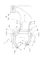
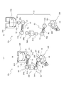
- FIG. 1A is a schematic view for explaining an example of the configuration of the operation assisting device 1 of the present invention, and shows the operation assisting device 1 conceptually.
- FIG. 1B is a schematic diagram for explaining another example of the configuration of the operation assisting device 1 of the present invention (operation assisting device 1'), and conceptually shows the operation assisting device 1'.
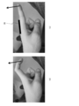
- FIG. 1C is a diagram showing a state in which the end nodes of the fingers are pulled up so as to open the fingers that imitate the state of the fingers of a patient with flexion contracture.
- FIG. 2 is an operation explanatory view of the operation assisting device 1 shown in FIG. 1A, and schematically shows a state in which the index finger F2 and the thumb F1 are extended by each arm 10 of the operation assisting device 1.
- FIG. 1A is a schematic view for explaining an example of the configuration of the operation assisting device 1 of the present invention, and shows the operation assisting device 1 conceptually.
- FIG. 1B is a schematic diagram for explaining another example of the
- FIG. 3 is an operation explanatory view of the operation assisting device 1 shown in FIG. 1A, and schematically shows a state in which the index finger F2 and the thumb F1 are started to be bent by the rotation of each arm 10 of the operation assisting device 1.
- FIG. 4 is an operation explanatory view of the operation assisting device 1 shown in FIG. 1A, and schematically shows a state in which the index finger F2 and the thumb F1 are bent until their tips come into contact with each other by further rotation of each arm 10 of the operation assisting device 1.
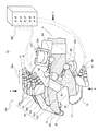
- FIG. 5 is a perspective view for explaining the operation assisting device 100 according to the first embodiment of the present invention, and schematically shows a state in which the operation assisting device 100 is attached to the user's hand H.
- FIG. 5 is a perspective view for explaining the operation assisting device 100 according to the first embodiment of the present invention, and schematically shows a state in which the operation assisting device 100 is attached to the user's hand H.
- FIG. 6 is a top view of the operation assisting device 100 of the first embodiment shown in FIG. 5, and specifically shows the structure of the operation assisting device 100 as viewed from the direction A of FIG.
- FIG. 7 is a bottom view of the operation assisting device 100 of the first embodiment shown in FIG. 5, and specifically shows the structure of the operation assisting device 100 as viewed from the B direction of FIG.
- FIG. 8 is a diagram for explaining a mechanism for moving the index finger F2 in the operation assisting device 100 of the first embodiment shown in FIG. 6, and FIG. 8A is a diagram showing the base member 31 as seen from the direction A in FIG. It is the top view which shows the arm 10 and the attachment member 30a, and FIG. 8 (b) is a side view which shows the structure of these members seen from the D direction of FIG.
- FIG. 9A and 9B are views showing a state in which the arm 10, the mounting member 30a, and the base member 31 shown in FIG. 8 are separated for each member, and FIG. 9A is a top view showing these members, FIG. 9B.
- FIG. 10 is a side view for explaining the rotation shaft adjusting mechanism 30c in the operation assisting device 100 of the first embodiment shown in FIG. 5, and is a side view of the base member 31 and the rotation shaft adjusting mechanism seen from the direction C of FIG. The structure of 30c is shown.
- FIG. 11 is a diagram for specifically explaining the rotating shaft adjusting mechanism 30c shown in FIG. 5, and FIG.
- FIG. 11A is a perspective view of the rotating shaft adjusting mechanism 30c seen from the same angle as FIG. 11 (b) shows the rotating shaft adjusting mechanism 30c shown in FIG. 11 (a) disassembled for each component.
- 12A and 12B are views for explaining the connection structure between the spherical columns 323 and 341a constituting the ball joints B1 and B2 shown in FIG. 11 and the first spherical socket member S1, and
- FIG. 12A is a diagram for explaining the connection structure of the ball. A state in which the joints B1 and B2 are assembled is shown, and FIG. 12B shows a state in which the ball joints B1 and B2 are disassembled.
- FIG. 13 is an operation explanatory view of the operation assisting device 1'shown in FIG.
- FIG. 14 is an operation explanatory view of the operation assisting device 1'shown in FIG. 1B, showing a state in which the index finger F2 and the thumb F1 are extended.
- FIG. 15 is a top view of an example of the base member 31 and the fixing member 32 of the arm support mechanism 30.
- FIG. 16 is a perspective view for explaining the operation assisting device 200 according to the second embodiment of the present invention.
- FIG. 1A is a schematic diagram for explaining an example of the configuration of the operation assisting device 1 of the present invention, and shows the operation assisting device 1 conceptually.
- An object of the present invention is to provide an operation assisting device having a simple mechanism for moving a finger, being lightweight, and reducing the burden on the user.
- An operation assisting device 1 that assists the bending and stretching of the user's fingers.
- At least one arm 10 At least one connecting member 20 configured to connect at least one arm 10 to a finger F (for example, thumb F1 and index finger F2), respectively.
- An arm support mechanism 30 that rotatably supports at least one arm 10 and is configured to be mounted on the instep Hb of the user's hand H.
- the arm driving means 40 for rotating at least one arm 10 is provided.
- At least one arm 10 is configured to rotate while maintaining a constant distance Dr between at least one connecting member 20 and the rotation center Cr (Cr1, Cr2) of at least one arm 10.
- Dr constant distance Dr between at least one connecting member 20 and the rotation center Cr (Cr1, Cr2) of at least one arm 10.
- FIG. 1B is a schematic diagram for explaining another example of the configuration of the operation assisting device 1 of the present invention (operation assisting device 1'), and conceptually shows the operation assisting device 1'.
- the configuration of the motion assist device 1' can be the same as the configuration of the motion assist device 1 except that the stopper 50 is provided. Therefore, the description of the operation assisting device 1 described later also applies to the operation assisting device 1'.
- the shape of the arm 10 is shown in a bent dogleg shape (or a greater-than sign ( ⁇ ) shape, a caret ( ⁇ ) shape), while in FIG. 1B, it is for the index finger F2.
- the shape of the arm 10 is shown in a substantially L-shape.
- the stopper 50 extends from the arm support mechanism 30 and regulates the movement of the proximal phalanx by contacting the proximal phalanx of the user's finger (the portion between the MP joint and the PIP joint (or IP joint)). It is configured in.
- the motion assist device 1' can efficiently move the user's finger. For example, when the user's finger is pulled up by the motion assist device 1', that is, the finger is moved so as to open the grasped finger, the stopper 50 abuts on the proximal phalanx to suppress the movement of the finger around the MP joint. On the other hand, it can promote movement around the PIP joint or the DIP joint.
- the connecting member 20 of the motion assist device 1' is to connect at least one arm 10 on the DIP joint of the finger or on the middle phalanx of the finger (the part between the DIP joint and the PIP joint). Is preferable. This is because the user's finger can be moved more efficiently. For example, when the user's finger is pulled up by at least one arm 10 connected on the DIP joint or middle phalanx of the finger, that is, when the finger is moved to open the grasped finger, the terminal phalanx (DIP joint (or or) of the finger). The fingers can be fully opened by pulling up the part) distal to the IP joint).
- Lifting the user's finger by at least one arm 10 connected on the DIP joint or intermediate phalanx of the finger efficiently pulls the user's finger in combination with the regulation of proximal phalanx movement by the stopper 50. It can be made to open completely.
- the stopper 50 abuts on the proximal phalanx to suppress the movement of the finger around the MP joint, while at least one arm 10 connected on the DIP joint or intermediate phalanx of the finger pulls up the distal phalanx to PIP. This is because the movement around the joint and the DIP joint can be promoted.
- FIG. 1C is a diagram showing a state in which the end nodes of the fingers are pulled up so as to open the fingers that imitate the state of the fingers of a patient with flexion contracture.
- the motion assist device 1 is not attached to the hand for the sake of brevity.
- the finger simply moves around the MP joint, as shown in FIG. 1C (a).
- the movement of the proximal phalanx of the finger is regulated by the stopper 50 to suppress the movement of the finger around the MP joint, so that the PIP joint and the DIP are shown in FIG. 1C (b). It can promote movement around the joints and allow the fingers of patients with flexion contracture to fully open. This can be useful, for example, during finger rehabilitation in patients with flexion contracture.
- FIG. 2 to 4 are operation explanatory views of the operation assisting device 1 shown in FIG. 1A
- FIG. 2 is a state in which the index finger F2 and the thumb F1 are extended
- FIG. 3 is a state in which the index finger F2 and the thumb F1 are started to be bent
- FIG. 4 shows a state in which the index finger F2 and the thumb F1 are bent until their tips are in contact with each other.
- the connecting member 20 attached to the arm 10 of the thumb F1 and the index finger F2 is attached by rotating the arm 10 supported by the arm supporting mechanism 30 by the arm driving means 40.
- the positions Cf1 and Cf2 are on the circumferences L1 and L2 centered on the rotation centers Cr1 and Cr2 of the respective arms 10. It becomes possible to move the finger F with a simple configuration in which one arm is rotated around one rotation center. In such an operation assisting device 1 of the present invention, a part of the link is replaced by the user's own skeleton.
- the arm 10 to which the index finger F2 is connected is supported by the attachment member 30a of the arm support mechanism 30, and the arm 10 to which the thumb F1 is connected is supported by the attachment member 30b of the arm support mechanism 30.
- the arm support mechanism 30 is the only rotating portion corresponding to the joint portion of the human finger, and the mechanism for moving the finger is simplified with only one rotating portion to reduce the weight. be able to.
- the arm 10 rotatably supported by the arm support mechanism 30 is connected to the finger F by the connecting member 20 and rotated by the arm driving means 40, at least 1 at that time. If the arm 10 rotates while maintaining a constant distance Dr between the connecting member 20 and the rotation center Cr of at least one arm 10, the arm 10, the connecting member 20, and the arm support mechanism 30
- the specific configuration of the arm driving means 40 is not particularly limited, and may be arbitrary.
- FIG. 13 to 14 are operation explanatory views of the operation assisting device 1'shown in FIG. 1B, FIG. 13 shows a state in which the index finger F2 and the thumb F1 are bent, and FIG. 14 shows the index finger F2 and the thumb F1 extended. Indicates the state.
- the motion assist device 1' In the motion assist device 1'with such a configuration, it is possible to move the finger F with a simple configuration in which one arm is rotated around one rotation center, as in the motion assist device 1.
- the proximal phalanx of the index finger F2 comes into contact with the stopper 50 as shown in FIG. This limits the movement of the proximal phalanx of the index finger F2 around the MP joint. Then, the index finger F2 is moved around the PIP joint or the DIP joint, and as a result, the index finger F2 is in a fully extended state.
- the stopper 50 regulates the movement of the proximal phalanx of the finger to suppress the movement of the finger around the MP joint, thereby promoting the movement around the PIP joint and the DIP joint, and flexion contracture.
- the finger of the patient can be fully opened.
- the shape of the arm 10 for the index finger F2 is substantially L-shaped, so that the arm 10 and the stopper 50 are prevented from interfering with each other.
- the means for avoiding interference between the arm 10 and the stopper 50 is not limited to this.
- a substantially L-shape for example, a curved shape or a substantially J-shape
- interference between the arm 10 and the stopper 50 can be avoided.
- it is possible to avoid interference between the arm 10 and the stopper 50 by making the stopper 50 a plurality of separate structures for each finger instead of having a continuous structure in the direction of crossing the hand.
- the stopper 50 by providing the stopper 50 with a slit through which the arm 10 can pass, interference between the arm 10 and the stopper 50 can be avoided.
- the motion assist device 1 Although the stopper corresponding to the thumb F1 is not depicted in the motion assist device 1'shown in FIGS. 1B and 13 to 14, the motion assist device 1'regulates the movement of the proximal phalanx of the thumb F1.
- a stopper may be provided.
- one finger of each of the five fingers is referred to as a finger F, and each finger and the arm 10 corresponding to each finger are described.
- the center of rotation is Cr
- the attachment position of the connecting member 20 to each finger and the arm 10 corresponding to each finger is Cf
- the locus of each finger is L.
- At least one arm 10 may be one arm 10 connected to any finger F of the five fingers, or as shown in FIG. 1A, an arm connected to the thumb F1. It may be two arms of 10 and an arm 10 connected to the index finger F2, or may include an arm 10 connected to at least one of the other fingers.
- the constituent material or its shape is particularly important. It is not limited and can be arbitrary. For example, at least one of metal, plastic, wood, ceramic, and the like may be used as the constituent material of the arm 10, or any combination of any of the above types may be used.
- the shape of the arm is not particularly limited, and may be linear or arcuate, and may be bent or curved. In a preferred embodiment, the arm 10 is in the shape of a dogleg (or greater-than sign ( ⁇ ), caret ( ⁇ )) that bends in a direction that wraps around the palm side.
- the bending angle can be any angle between 0 ° and 180 °, for example 90 °, 120 °, 135 °, 150 ° and the like.
- the structure of the arm 10 can be arbitrary.
- the arm 10 is composed of a plate-like member having no joint between its rotation center and the connecting member 20.
- the arm 10 is composed of one plate-shaped member having no joint between its rotation center and the connecting member 20.
- the arm 10 is composed of a plurality of members having no joint between its rotation center and the connecting member 20.
- the length of the arm 10 can be variably configured by movably connecting each of the plurality of members. This makes it possible to adjust the length of the arm 10 according to the length of the fingers of the user's hand.
- the shape of the arm 10 may be a plate-shaped member or a rod-shaped member.
- the arm 10 is a plate-like member.
- the arm 10 By making the arm 10 a plate-shaped member, it becomes easy to arrange the arm 10 along the side surface of the finger F instead of arranging the arm 10 on the upper surface side of the finger F.
- the arm 10 By arranging the arm 10 along the side surface of the finger F, not only a sense of unity with the finger can be obtained, but also the arm 10 interferes with the finger F when the arm 10 is rotated in the direction in which the finger F bends. Can be suppressed.
- the arm 10 may be hollow, or a slit or a hole may be provided within a range in which a predetermined strength is maintained.
- connection member 20 The constituent material and shape of the connecting member 20 are not particularly limited as long as the finger F can be connected to the arm 10.
- the connecting member 20 may be made of cloth, leather, resin, paper, or rubber.
- the shape of the connecting member 20 may be a flat plate shape, a belt shape, or an annular shape.
- the connecting member 20 can be made of a plurality of materials.
- the connecting member 20 may be formed of a plurality of materials having different rigidity.
- the connecting member 20 can be formed, for example, from a first material having a first rigidity and a second material having a second rigidity higher than that of the first material.
- the first material having the first rigidity is a material softer than the second material and includes, for example, cloth, leather, natural fiber, synthetic fiber (for example, nylon), resin (for example, PTFE) and the like. Not limited to these.
- the first material can be, for example, a hook-and-loop fastener (eg, Velcro®).
- the material having the second rigidity is a material harder than the first material, and includes, but is not limited to, for example, glass, resin (for example, nylon resin, ABS) and the like.
- the second material can be, for example, a 66 nylon glass filler.
- the plurality of materials forming the connecting member 20 may be selected, for example, to achieve the desired properties.
- the portion of the connecting member 20 that comes into contact with the finger pad of the finger F is made of a highly rigid material (that is, a hard material), and the other portion is made of a low-rigidity material (that is, a soft material). Can be formed.
- the ease of attaching the connecting member 20 to the finger F can be maintained, and the connectivity between the arm 10 and the finger F can be improved.
- it is effective to detect the intention to move the body and assist the movement of the body according to the intention.
- the mounting position of the user's finger on the connecting member 20 can be arbitrary.
- the connecting member 20 may be arranged around the DIP joint of the finger F
- the connecting member 20 may be arranged around the PIP joint of the finger F
- the connecting member 20 may be arranged around the DIP joint of the finger F. It may be placed between the PIP joint and the PIP joint.
- the connecting member 20 is placed around the DIP joint of the finger F or between the DIP joint and the PIP joint.
- the method of connecting the connecting member 20 to the finger may be arbitrary.
- a belt-shaped connecting member may be wrapped around a finger, a finger may be inserted into an annular connecting member, or a flat plate-shaped connecting member may be bonded to a finger (for example, a nail). It may be a method of fixing with an agent or the like.
- the connecting member 20 is a resin belt having a resin buckle and adjustable tightening strength, but is not limited thereto.
- the connecting member 20 has a hook-and-loop fastener.
- the connecting member 20 is attached so as to be rotatable with respect to the arm 10. This is because the rotation of the connecting member 20 with respect to the arm 10 can prevent the posture of the finger F with respect to the arm 10 from being fixed to a constant posture by the connecting member 20, and the finger F is fixed to the arm 10 by the connecting member 20. It is possible to eliminate the possibility that a feeling of strangeness such as the F being tightened is caused by the rotation of the arm 10.
- the connecting member is configured to connect the arm to the finger so that the tip of the finger is exposed.
- the tip of the finger F finger tip
- the connecting member 20 is not covered by the connecting member 20, so that the tip of the thumb F1 and the tip of the index finger F2 come into direct contact with the object when grasping an object. , It is possible to make the user feel more like grasping an object.
- the arm support mechanism 30 is not particularly limited in any other configuration as long as it rotatably supports at least one arm 10, and may be arbitrary.
- the arm support mechanism 30 has a base portion arranged on the back of the hand and a mounting member for rotatably attaching the arm to the base portion so as to rotatably support the arm 10.
- the base is, for example, a base member 31 that can be mounted on a portion (for example, instep Hb) other than the fingers of the user's hand.
- the base member is fixed to the user's hand H by the fixing member.
- the material or shape of the base member can be arbitrary.
- the constituent material of the base member at least one of metal, plastic, wood, ceramic and the like may be used, or any combination of any of the above types may be used.
- the base member may be hollow as long as a predetermined strength is maintained, or slits or holes may be provided.
- the fixing member can be in any form.
- it may be a belt or string made of leather, cloth, resin, etc., or it may be a peelable adhesive member such as silicone.
- the arm support mechanism is configured so that, for example, the position and / or orientation of the base member with respect to the back of the user's hand can be adjusted.
- the base member can be adjusted according to the size and / or shape of the user's hand.
- the position of the base member can be adjusted in the longitudinal direction of the hand according to the size of the user's hand.
- the mechanism for adjusting the position and / or orientation of the base member which can adjust the orientation of the base member on a plane parallel to the back of the hand according to the shape of the user, can be any mechanism. ..
- Such an arm support mechanism can be achieved, for example, by allowing the position and / or orientation of the base member with respect to the fixing member to be adjustable.
- the mounting member has at least one arm as a base member and rotatably supports the arm around the center of rotation, and is in any form as long as it can be arranged on the base member 31.
- the mounting member may have a shaft member fixed to the base portion (base member), and one end of the arm 10 may be rotatably supported by the shaft member, or the mounting member may be mounted on the base portion.
- the flexible member may be provided, and one end of the arm may be rotatably supported by the flexible member.
- the flexible member can be, for example, a leaf spring, a coil spring, an elastic frame member, or the like.
- the present invention is not limited to this.
- the posture and position of the finger can be uniquely determined according to the bending and stretching of the finger. It is one of the features of the finger assist device of the present invention that it is possible.
- At least one arm 10 can be arranged at any position.
- the arm support mechanism 30 is such that the center of rotation of at least one arm 10 is located on the MP joint of the finger F (the joint at the base of the finger F) or on the wrist side of the MP joint. It is configured. By arranging the rotation axis on the MP joint of the finger F (the joint at the base of the finger F) or on the wrist side of the MP joint in this way, it is possible to move the MP joint according to the flexion and extension of the finger. ..
- a mounting member is arranged on a base member 31 that can be mounted on the back of the hand Hb, and the mounting member is rotated around the center of rotation with at least one arm as the base member. This can be achieved by making the configuration movably supported.
- the arm support mechanism 30 may be configured so that the mounting position of at least one arm with respect to the base member 31 can be adjusted in the longitudinal direction of the finger. By doing so, the position of the rotation center of the arm can be adjusted according to the size of the user's hand.
- the mounting member may be configured so that the fixed position of the arm with respect to the mounting members 30a and 30b can be adjusted in the longitudinal direction of the finger.
- the base member 31 may be configured so that the fixing positions of the mounting members 30a and 30b with respect to the base member 31 can be adjusted in the longitudinal direction of the finger.
- the mounting members 30a and 30b are configured so that the fixed position of the arm 10 with respect to the mounting members 30a and 30b can be adjusted in the longitudinal direction of the finger, and the base member 31 is mounted on the base member 31.
- the fixed positions of the members 30a and 30b may be adjustable in the longitudinal direction of the finger.
- the arm support mechanism 30 may be configured such that the mounting position of at least one arm 10 with respect to the base member 31 cannot be adjusted.
- the arm support mechanism 30 may include an adjustment mechanism for adjusting the position and / or orientation of the rotation shaft of the arm 10.
- the arm 10 is connected to the base member 31 via the rotation shaft adjusting mechanism (for example, the arm 10 supporting the thumb F1) and to the base member 31 without the rotation shaft adjusting mechanism.
- the rotation shaft adjusting mechanism for example, the arm 10 supporting the thumb F1
- an arm 10 that supports a finger F other than the thumb F1 may be included.
- all the arms 10 may be connected to the base member 31 via a rotation shaft adjusting mechanism.
- the rotation axis adjusting mechanism may include one or a plurality of ball joints, but is not limited to the ball joints, and when fixing the two members, the posture of the other member with respect to one member is arbitrary. It may have a connection mechanism that can be set to the above instead of the ball joint.
- the rotating shaft adjusting mechanism can be configured to be selectively mountable on both the first side and the second side of the base member 31, for example.
- one motion assisting device 1 can be configured for both hands.
- the rotation axis adjusting mechanism is attached to the first side of the base member 31 (for example, the left side of the central axis of the base parallel to the longitudinal direction of the hand)
- the motion assist device 1 is for one hand (for example, for one hand).
- the right hand This is because when the base member 31 is attached to the back of the hand, the arm 10 that supports the thumb F1 comes to the left side of the base portion 31.
- the operation assisting device 1 is already attached. It is an operation assist device for one hand (for example, for the left hand). This is because when the base member 31 is attached to the back of the hand, the arm 10 that supports the thumb F1 comes to the right side of the base portion 31.
- the operation assisting device 1 includes a plurality of arms 10 and a plurality of mounting members
- the plurality of mounting members may be mounted on the base member so that the distance between the plurality of mounting members can be adjusted. This makes it possible to adjust the spacing between the plurality of arms 10 according to the finger spacing of the user.
- the arm driving means 40 is not particularly limited as long as it rotates the rotatably supported arm 10, and the specific structure may be arbitrary.
- the arm driving means 40 may have a wire portion 40a including a wire directly or indirectly connected to the arm 10 and a wire driving portion 40b for pulling the wire.
- the wire portion 40a has two first and second wires 41 and 42 attached to a mounting member that rotatably supports the arm 10 on the base member 31, and pulls the first wire 41.
- the finger F may be bent by rotating the arm 10 in one direction, and the finger F may be extended by rotating in the direction opposite to the one-way rotation of the arm 10 by pulling the second wire 42.
- the means for pulling the wire may be attached to a part other than the hand of the user's body, or may be provided away from the user's body.
- the means for pulling the wire may include a motor, a pneumatic or hydraulic piston, or an electromagnet as a drive source.
- the arm driving means may be attached to the user's hand, and in this case, the arm may be connected to a driving source such as a motor or a piston of the arm driving means by a link mechanism that does not use a wire.
- the wire drive unit is provided on a portion other than the user's body (particularly other than the hand). By doing so, the user does not have to bear the weight of the wire driving unit, so that the finger movement can be performed more smoothly.
- the motion assist device 1 further includes a sensor that detects a myoelectric signal generated when the user tries to move a finger, and a vibrating means that vibrates when the sensor detects the myoelectric signal. May be good.
- the arm driving means 40 detects the intention of the user to move the finger from a biological signal such as a myoelectric signal or an electroencephalogram and drives the arm 10, but detects the intention and actually drives the arm 10. There will be a time lag before. In this case, the user may feel uncomfortable that the arm 10 does not start moving immediately even if he / she tries to move his / her finger. As a method for improving such a state, it may be effective to detect the myoelectric signal and at the same time give vibration to the user's hand H by the vibrating means. Since the vibrating means vibrates almost at the same time as the user's intention, it is possible to reduce the user's discomfort due to the time lag in driving the arm 10.
- a biological signal such as a myoelectric signal or an electroencephalogram
- the arm support mechanism 30 further comprises a first encoder that detects the rotation angle of the arm 10, and the arm drive means 40 provides a second encoder that detects the rotation angle of the motor of the wire drive unit 40b. You may also have more.
- the rotation angle of the motor can be indirectly detected, for example, by the second encoder detecting the rotation angle of the pulley attached to the motor.
- the operation assisting device 1 further provides a calculation means for calculating the tension of the wire portion 40a based on the rotation angle detected by the first encoder and the rotation angle detected by the second encoder. Can be prepared. For example, when the rotational motion of the arm 10 resists the rotational motion of the motor, a difference occurs between the rotational angle of the motor and the rotational angle of the arm 10. This difference can be used as an index of the tension acting on the wire portion 40a. In this configuration, the calculating means can calculate the tension acting on the wire portion 40a without using the force sensor, which is useful for simplifying the configuration of the operation assisting device 1.
- the tension calculated by the calculation means can be used in the operation assisting device 1 to control the operation assisting device 1 for various purposes.
- it can be used as a torque limiter to prevent excessive force from acting on the user's finger.
- it can be used so that the user can grip the object with a constant force regardless of the size of the gripped object.
- it can be used to enable the assist force to be adjusted according to the recovery of the user (for example, a rehabilitation patient).
- it can be used to control the motion assist device 1 so that the motion of the motion assist device 1 does not interfere with the movement of the user.
- a control mode is referred to as a motion sensing mode.
- It is preferable to control the motion assisting device 1 in the motion sensing mode for example, when the user is moving his / her fingers within the range of his / her own movement.
- the motion assisting device 1 can be prevented from interfering with the movement of the user within the range in which the user can move by himself / herself.
- the intention of the user to move the finger is detected from biological signals such as myoelectric signals and brain waves, and the arm 10 is controlled in the motion sensing mode instead of being driven. By doing so, it is possible to reduce erroneous recognition related to biological signal sensing.
- the drive source (wire drive unit) of the arm drive means 40 is arranged around the user, and the drive force of the drive source of the arm drive means 40 is armed by the wires 41 and 42. List what is transmitted to 10.
- the arm support mechanism 30 has a base member 31 that can be mounted on the back of the hand, and mounting members 30a and 30b that rotatably support the arm 10 on the base member 31 around the center of rotation. It is assumed that the fixed positions of the mounting members 30a and 30b with respect to 31 and the fixing positions of the arm 10 with respect to the mounting members 30a and 30b can be adjusted in the longitudinal direction of the finger F.
- the arm 10 is configured to have a structure having no joint between the rotation center and the connecting member.
- FIG. 5 is a perspective view for explaining the operation assisting device 100 according to the first embodiment of the present invention, and schematically shows a state in which the operation assisting device 100 is attached to the user's hand H. 6 and 7 are top and bottom views of the operation assisting device 100, respectively, FIG. 6 shows the structure of the operation assisting device 100 as viewed from the direction A of FIG. 5, and FIG. 7 is a diagram. The structure of the operation assisting device 100 seen from the B direction of No. 5 is specifically shown.
- the motion assisting device 100 of the first embodiment assists the bending and stretching of the user's fingers, and one of its uses is, for example, rehabilitation of the fingers of the hand when the user is a person with a dysfunction.
- the user may be a motion aid for a person with weak fingers.
- measurement of the range of motion of a finger joint when a user voluntarily bends and stretches a finger and driving of a robot hand of a remote control robot having an arm such as an avatar robot can be performed. There may be an interface for control.
- a motor is used as a driving means of the operation assisting device, but by weakening the motor, the angle of the motor (opening / closing degree of the finger) can always be monitored. Utilizing this, it is possible to measure the range of motion of the joint when the user bends and stretches the finger by spontaneous movement.
- the hand of the avatar robot can be driven based on the angle (opening / closing degree of the finger) of the motor of the driving means obtained by the movement of the user wearing the motion assisting device, and the hand of the avatar robot can be driven.
- the motion assist device is an interface for controlling the driving of the robot hand of the avatar robot. Can be.
- the operation assisting device 100 includes an arm 10, a connecting member 20 for connecting a finger F to the arm 10, an arm support mechanism 30 for rotatably supporting the arm 10, and an arm driving means 40 for rotating the arm 10.
- the arm 10 is configured to rotate while maintaining a constant distance between the connecting member 20 and the rotation center of the arm 10.
- the arm 10 and the connecting member 20 are provided for each of the five fingers F1 to F5 of the user's hand H, respectively, and the arm 10 and the connecting member 20 have the same configuration as those corresponding to any finger. is doing.
- the motion assisting device 100 does not necessarily have to be provided with the arm 10 and the connecting member 20 corresponding to all five fingers, and may be only one corresponding to the thumb F1 or only the one corresponding to the index finger F2. , Only those corresponding to the other fingers of the five fingers may be provided.
- the arm 10 has a structure having no joint between its rotation center and the connecting member 20, and as shown in FIG. 5, the entire arm is composed of one plate-shaped member, and the entire arm is formed. It has a bent shape (or a greater-than sign ( ⁇ ) shape, a caret ( ⁇ ) shape).
- a belt member whose tightening strength can be adjusted is attached to the tip of the arm 10 as a connecting member 20, and the belt member 20 is attached to the first joint of, for example, a finger (for example, thumb F1 person and index finger F2 in FIG. 5).
- the arm 10 can be connected to the thumb F1 and the index finger F2 by wrapping and fixing the arm 10 around the tip portion.
- the base portion of the arm 10 is rotatably supported by the arm support mechanism 30.
- the belt member as the connecting member 20 has a structure in which the arm 10 can be connected to the finger F so that the tip of the finger F is exposed.
- the arm 10 may be a plurality of plate-shaped members, or may be composed of at least one rod-shaped member.
- the fingers other than the thumb F1 and the index finger F2 are also connected to the connecting member 20 so that the portion of the arm 10 beyond the first joint is the same as the index finger F2. It is fixed to the tip of the frame piece 10a of 1.
- the root portion of the arm 10 corresponding to these fingers F3 to F5 is rotatably supported by the arm support mechanism 30.
- the arm 10 of each finger rotates while keeping the distance Dr (see FIG. 1) between the attachment position Cf of the connecting member 20 and the rotation center Cr of the arm 10 constant. It will be supported by the arm support mechanism 30 so as to move.
- the arm support mechanism 30 may include a base member 31, four attachment members 30a corresponding to fingers F2 to F5 other than the thumb, and one attachment member 30b corresponding to the thumb F1.
- the fixing member may have fixing members 32a and 32b for fixing the base member 31 to the user's hand H.
- the fixing member may be only one of the fixing member 32a and the fixing member 32b.
- the fixing member may be in any form as long as the base member 31 can be fixed to the user's hand H.
- it may be made of cloth, leather, resin, paper, or rubber.
- the shape of the fixing member may be a flat plate shape, a belt shape, or an annular shape.
- the method of fixing the hand of the fixing member may be arbitrary.
- a belt-shaped fixing member may be wound around the hand, a hand may be inserted into the annular fixing member, or a flat plate-shaped fixing member may be fixed to the hand with an adhesive or the like. It may be a method.
- the fixing member is attached to the instep side fixing member 32a attached to the portion of the base member 31 that covers a part of the instep Hb of the hand H, and the wrist of the user of the base member 31. It is a wrist-side fixing member 32b attached to the contacting portion.
- the instep side fixing member 32a has a belt shape and has a structure that can be wrapped around the palm part and fixed by a magic tape (registered trademark) or a buckle
- the wrist side fixing member 32b has a belt shape and is wrapped around the wrist. It has a structure that can be fixed with a hook-and-loop fastener (for example, Magic Tape (registered trademark), Velcro (registered trademark)) or a buckle.
- the arm support mechanism 30 may be configured so that the position and / or orientation of the base member 31 with respect to the back of the hand can be adjusted. This can be achieved, for example, by the configuration shown in FIG.
- FIG. 15 is a top view of an example of the base member 31 and the fixing member 32 of the arm support mechanism 30.
- the right side of FIG. 15 is the direction in which the user's finger extends. That is, the base member 31 has a front side (right side in FIG. 15) on which at least one arm 10 extends in the operation assisting device 100, and a rear side (left side in FIG. 15) opposite to the front side.
- the base member 31 has a plane that is substantially parallel to the back of the user's hand when attached to the user's hand.
- the base member 31 includes a fixing means 3101 and a slot 3102.
- the fixing means 3101 is fixed to the fixing member 32 through the slot 3102.
- the base member 31 can move relative to the fixing member 32 by the length of the slot 3102. Since the fixing member 32 is fixed to the back of the user's hand by the back-side fixing member 32a and the wrist-side fixing member 32b, the relative movement of the base member 31 with respect to the fixing member 32 is, by extension, relative movement with respect to the back of the hand. Become. Thereby, the position of the base member 31 with respect to the back of the hand can be adjusted.
- the fixing member 32 includes a member 3201 that covers the base member 31.
- the member 3201 is fixed to the fixing member 32 at both ends, whereby a passage through which the base member 31 passes can be formed between the fixing member 32 and the member 3201.
- the base member 31 can move in the passage.
- the base member 31 can be pivotally moved relative to the fixing member 32 with the fixing means 3101 as a fulcrum. Since the fixing member 32 is fixed to the back of the user's hand by the back-side fixing member 32a and the wrist-side fixing member 32b, the relative pivot of the base member 31 with respect to the fixing member 32 is, by extension, the relative pivot with respect to the back of the hand. It becomes a movement. Thereby, the orientation of the base member 31 with respect to the back of the hand can be adjusted.
- mounting members 30a corresponding to fingers F2 to F5 other than the thumb F1 are fixed to the base member 31 which is the base of the arm support mechanism 30, and the arm 10 is rotatably supported by each mounting member 30a.
- the mounting member 30b corresponding to the thumb F1 is preferably fixed to the base member 31 via the rotation shaft adjusting mechanism 30c, and the arm 10 is rotatably supported by the mounting member 30b.
- the rotation shaft adjusting mechanism 30c constitutes a part of the arm support mechanism 30, and by having one or more ball joints, the position and / or orientation of the rotation shaft of the arm 10 corresponding to the thumb F1. Can be adjusted in various directions.
- a rotating shaft adjusting mechanism capable of adjusting the position and / or orientation of the rotating shaft in this way, it is required to move to a more complicated movement (position or orientation) than other fingers like a thumb. It is possible to respond to the movement of the finger to be performed and the position and orientation of the finger that differ depending on the person.
- the present invention is not limited to this.
- a rotation axis adjusting mechanism may be used for the movement of fingers other than the thumb.
- the rotation shaft adjusting mechanism 30c can be configured to be selectively mountable on both the first side and the second side of the base member 31.
- one motion assisting device 100 can be configured for both hands.
- the operation assisting device 100 is for one hand (for example).
- it is an operation assisting device for the right hand).
- the operation assisting device 100 It is an operation assist device for the other hand (for example, for the left hand). This is because when the base member 31 is attached to the back of the hand, the arm 10 that supports the thumb F1 comes to the right side of the base portion 31.
- the arm support mechanism 30 may be configured so that the mounting position of the arm 10 with respect to the base member 31 can be adjusted in the longitudinal direction of the finger (the direction in which the arm 10 extends).
- the base member 31 sets the fixing positions of the mounting members 30a and 30b with respect to the base member 31. It may be configured to be adjustable in the longitudinal direction of the finger F (the direction in which the arm 10 extends), and the mounting members 30a and 30b set the fixed position of the arm 10 with respect to the mounting members 30a and 30b in the longitudinal direction of the finger F (arm). It may be configured to be adjustable in the extending direction of 10.
- the arm support mechanism 30 may each have an adjustment mechanism for the mounting positions of the two arms 10.
- each arm 10 in the arm support mechanism 30, as shown in FIGS. 1 to 5, is on the MP joint of the finger F (joint at the base of the finger) or. It is configured to be placed on the wrist side of the MP joint.
- mounting members 30a and 30b are arranged on a base member 31 mounted on the back of the hand Hb, and each of the mounting members 30a and 30b has an arm as a base member 31. It is realized by a configuration that rotatably supports around the center of rotation.
- the arm driving means 40 drives the four mounting members 30a corresponding to the fingers F2 to F5 and the arm 10 rotatably mounted on the mounting member 30b corresponding to the thumb F1.
- each arm is driven. It has a wire portion 40a including a pair of wires for moving the 10 (first wire 41 and a second wire 42), and a wire driving portion 40b for pulling a pair of wires for moving each arm 10.
- the wire portion 40a includes a first wire 41 and a second wire 42 connected to the wire drive portion 40b, and a mechanism for connecting these wires to the arm 10, and the driving force of the wire drive portion 40b. Is converted into the rotational force of the arm 10 by the first wire 41 and the second wire 42, and the arm 10 is rotated in one direction or the opposite direction by the driving force of the wire driving unit 40b.
- the motion assist device 100 includes a sensor (not shown) that detects a myoelectric signal generated when the user tries to move a finger, and a vibrating means that vibrates when the sensor detects the myoelectric signal.
- a control unit that controls the wire drive unit 40b to pull the first and second first wires 41, 42 connected to the arm 10 corresponding to a predetermined finger based on the detection of the myoelectric signal by the sensor (shown in the figure). It may have (1) and.
- the arm driving means 40 detects the intention of the user to move the finger from myoelectric signals, brain waves, and the like to drive the arm 10, but there is a time lag until the intention is detected and the arm 10 is actually driven. Occurs.
- the user may feel uncomfortable that the arm 10 does not start moving immediately even if he / she tries to move his / her finger.
- it may be effective to detect the myoelectric signal and at the same time give vibration to the user's hand H by the vibrating means. Since the vibrating means vibrates almost at the same time as the user's intention, it is possible to reduce the user's discomfort due to the time lag in driving the arm 10.
- the arm support mechanism 30 further includes a first encoder for detecting the rotation angle of the arm 10, and the arm driving means 40 connects the first and second first wires connected to the arm 10.
- a second encoder that detects the rotation angle of the motor that drives 41 and 42 may be further provided.
- the operation assisting device 100 further provides a calculation means (not shown) for calculating the tension of the wire portion 40a based on the rotation angle detected by the first encoder and the rotation angle detected by the second encoder. Can be prepared.
- the tension calculated by the calculation means can be used in the operation assisting device 100 to control the operation assisting device 100 for various purposes.
- it can be used as a torque limiter to prevent excessive force from acting on the user's finger.
- it can be used so that the user can grip the object with a constant force regardless of the size of the gripped object.
- it can be used to enable the assist force to be adjusted according to the recovery of the user (for example, a rehabilitation patient).
- it can be used to control the movement assisting device 100 so that the movement of the movement assisting device 100 does not interfere with the movement of the user.
- FIG. 8 is a diagram for explaining a mechanism for moving the index finger F2 in the operation assisting device 100 of the first embodiment shown in FIG. 6, and FIG. 8A is a diagram showing the base member 31 as seen from the direction A in FIG. It is the top view which shows the arm 10 and the attachment member 30a, and FIG. 8 (b) is a side view which shows the structure of these members seen from the D direction of FIG. 8 (a).
- 9A and 9B are views showing a state in which the arm 10, the mounting member 30a, and the base member 31 shown in FIG. 8 are separated for each member, and FIG. 9A is a top view showing these members, FIG. 9B. ) Is a side view showing the structure of these members as seen from the D direction of FIG. 9A.
- the arm 10 includes an arm body 101 made of a plate-shaped member and an arm fixing piece 102 which is a portion for fixing the arm 10 to the mounting member 30a.
- the arm body 101 includes a first frame piece 101a and a second frame piece 101b, and the angle K formed by the center lines La and Lb of the first frame piece 101a and the second frame piece 101b is obtuse. It is integrally joined so as to form a sword, and has an obtuse-shaped bent shape as a whole.
- the arm 10 has a structure having no joint between its rotation center (center of the wheel shaft member 302a) and the connecting member 20. By doing so, a complicated mechanism is not required for the rotation of the arm, and it is possible to reduce the weight with a simple structure.
- a belt member is attached to the tip of the first frame piece 101a as a connecting member 20, and the belt member 20 is wound around a portion of a finger (see, for example, the index finger F2 in FIG. 5) beyond the first joint.
- the arm 10 can be connected to the index finger F2 by fixing the arm 10.
- an arm fixing piece 102 is formed on the second frame piece 101b, and the arm fixing piece 102 is fixed to the mounting member 30a.
- the mounting member 30a includes a mounting member housing 301, a rotating wheel 302, an arm support piece 303, and a fixture mounting portion 304.
- the mounting member housing 301 may include an arm support portion 301a and a member fixing piece 301b.
- the arm support portion 301a and the member fixing piece 301b may be formed separately or integrally.
- the constituent material of the mounting member 30a is not particularly limited, but resin, metal, ceramic, hard rubber and the like can be used.
- the mounting member 30a is formed by resin molding and has carbon for reinforcement inside. It may contain fibers such as fibers, metal fibers, and resin fibers.
- a rotary wheel 302 for rotating the arm is rotatably supported by the wheel shaft member 302a on the arm support portion 301a, and an arm support piece 303 to which the arm 10 is attached is fixed to the rotary wheel 302.
- the foil shaft member 302a may be made of resin or metal in terms of durability and the like.
- An arm fixing lever 303a for detachably fixing the arm fixing piece 102 of the arm 10 is attached to the arm support piece 303.
- the support column 303b is fixed to the plate-shaped member which is the arm support piece 303
- the arm fixing lever 303a is rotatably attached to the support pin 303c fixed to the support column 303b. Since the root portion has a cam shape and the width of the gap between the root portion and the plate-shaped member changes due to the rotation of the arm fixing lever 303a, the gap between the root portion and the plate-shaped member changes.
- the arm fixing piece 102 of the arm 10 can be sandwiched and fixed or released.
- the arm support piece 303 and the arm fixing piece 102 may be in any form as long as the relative positions of the two can be adjusted.
- the upper surface of the arm support piece 303 (the surface of the arm 10 in contact with the arm fixing piece 102) has a corrugated plate shape (not shown) in which linear irregularities are repeatedly arranged at a constant pitch.
- the lower surface of the arm fixing piece 102 (the surface of the mounting member 30a in contact with the arm support piece 303) also has a corrugated plate shape (not shown) in which linear irregularities are repeatedly arranged at a constant pitch.
- the direction in which the linear unevenness extends is a direction parallel to the direction of the rotation axis 302a of the rotating wheel 302, and the arrangement direction of the linear unevenness is the direction in which the arm 10 extends (longitudinal direction).
- the arm fixing piece 102 is formed with a slit 102a along the longitudinal direction of the arm 10.
- the mounting member 30a has a structure in which the fixing position of the arm 10 with respect to the mounting member 30a can be adjusted stepwise in the longitudinal direction of the finger F (the direction in which the arm 10 extends) in pitch units of the linear unevenness. There is.
- the linear unevenness of the arm support piece 303 of the mounting member 30a and the linear unevenness of the lower surface of the arm fixing piece 102 of the arm 10 in this way, the mounting position of the arm 10 with respect to the mounting member 30a is prevented from shifting. It is possible to avoid it.
- the arm support piece is not provided with linear unevenness on the arm support piece and the arm fixing piece, and the arm support piece is used by using a slide mechanism or the like in which the support support column 303b of the arm support piece 303 slides relatively in the slit 102a of the arm fixing piece 102 described above.
- the relative position between the arm and the arm fixing piece may be adjustable.
- the arm support portion 301a further includes a pair of fixture attachment portions 304 to which the wire fixtures 41a and 42a are attached, and the wire fixtures 41a and 42a include a pair of wires 41 including wire core members 41b and 42b.
- the structure is such that 42 can be connected.
- the wire fixtures 41a and 42a may be made of resin like the arm support portion 301a, or may be made of metal in terms of durability and the like.
- the arm support portion 301a is formed with holes (not shown) through which the pair of wire core members 41b and 42b pass, respectively.
- One wire core material 41b is bound to the arm 10 side portion of the upper half portion of the rotating foil 302 via the arm support portion 301a, and the first wire 41 including the wire core material 41b holds the finger F. It is an extension wire for extension.
- the other wire core material 42b is bound to the arm 10 side portion of the lower half portion of the rotating foil 302 via the arm support portion 301a, and the second wire 42 including the wire core material 42b holds the finger F. It is a bending wire 42 for bending.
- the member fixing piece 301b may have any form as long as the position can be adjusted with respect to the base member 31.
- the member fixing piece 301b may have any form as long as the position can be adjusted with respect to the base member 31.
- linear irregularities are repeatedly arranged at a constant pitch on the lower surface (the surface in contact with the base member 31) of the member fixing piece 301b, similarly to the arm support piece 303. It has a corrugated iron shape ((not shown)).
- the present invention is not limited to this.
- the lower surface of the member fixing piece 301b may not have a corrugated plate shape in which linear irregularities are repeatedly arranged at a constant pitch, but the position may be adjustable with respect to the base member 31 by providing a slide mechanism.
- a mounting member fixing lever 31a for detachably fixing the member fixing piece 301b of the mounting member 30a is attached to a portion of the base member 31 on which the mounting member 30a is arranged.
- the support column 31b is fixed to the plate-shaped member which is the base member 31, and the mounting member fixing lever 31a is fixed to the support column 31b like the arm fixing lever 303a of the mounting member 30a.
- the root portion has a cam shape, and the width of the gap between the root portion and the plate-shaped member which is the base member 31 due to the rotation of the attachment member fixing lever 31a. Therefore, the member fixing piece 301b of the mounting member 30a can be sandwiched between the root portion and the base member 31 to be fixed or unfixed.
- the base member 31 may be in any form as long as the position can be adjusted with respect to the member fixing piece 301b.
- the upper surface of the portion of the base member 31 on which the mounting member 30a is arranged has a corrugated plate shape (not shown) in which linear irregularities are repeatedly arranged at a constant pitch, and the base member 31 has a corrugated plate shape (not shown).
- the linear unevenness formed on the upper surface thereof may be fitted with the unevenness formed on the lower surface of the member fixing piece 301b of the mounting member 30a.
- the direction in which the linear unevenness extends here is a direction parallel to the direction of the rotation axis of the rotating wheel 302, and the arrangement direction of the linear unevenness is a direction in which the arm 10 extends (longitudinal direction).
- the member fixing piece 301b is formed with a slit 311b along the longitudinal direction of the arm 10.
- the mounting member 30a is attached to the base member 31. It is possible to avoid misalignment.
- the present invention is not limited to this.
- the support column 31b of the base member 31 is formed in the slit 311b of the member fixing piece 301b of the mounting member 30a described above.
- the position may be adjustable with respect to the member fixing piece 301b by providing a slide mechanism that slides.
- the arm 10 is rotatably supported by the mounting member 30b corresponding to the thumb F1. Further, the mounting member 30b is fixed to the base member 31 via the rotating shaft adjusting mechanism 30c.
- the rotation shaft adjusting mechanism 30c adjusts the position and / or orientation of the rotation shaft of the arm 10, and is attached to the base member 31 so as to be adjustable in the width direction of the hand H.
- FIG. 10 is a side view for explaining the rotation shaft adjusting mechanism 30c in the operation assisting device 100 of the first embodiment shown in FIGS. 5 to 7, and the base member 31 and rotation seen from the C direction of FIG.
- the structure of the shaft adjusting mechanism 30c is shown.
- FIG. 10 for convenience of explanation, the posture of the third bracket 330 with respect to the second bracket 320 is different from that of FIGS. 5 to 7.
- the rotation shaft adjusting mechanism 30c has a first bracket 310 fixed to the base member 31 so as to be position-adjustably fixed in the width direction Wh of the hand H, and a first bracket 310 in the height direction on the base member 31. It has a second bracket 320 that is fixed in a position-adjustable manner, and a third bracket 330 in which the mounting member 30b corresponding to the thumb F1 is fixed in a position-adjustable direction in the extending direction of the arm 10.
- the base member 31 has a structure in which the first bracket 310 can be fixed to the base member 31 by the bottom surface side fixing lever 311a in the same manner as the fixing of the base member 31 and the member fixing piece 301b of the mounting member 30a.
- the second bracket 320 has a structure in which the second bracket 320 can be fixed to the first bracket 310 by the side fixing lever 322a. Further, the second bracket 320 and the third bracket 330 are connected via four ball joints B1, B2, B3, and B4.
- the first bracket 310 is an L-shaped angle member having a bottom surface portion 311 and a side surface portion 312, and is located on a portion of the base member 31 on which the bottom surface portion 311 of the first bracket 310 is arranged. Is attached with a bottom surface side fixing lever 311a for detachably fixing the bottom surface portion 311 of the first bracket 310.
- the bottom side fixing lever 311a is rotatably mounted via a support column (not shown) fixed to the plate-shaped member which is the base member 31, and has a root portion. It has a cam shape, and the width of the gap between the root portion and the plate-shaped member which is the base member 31 changes due to the rotation of the bottom surface side fixing lever 311a.
- the bottom surface portion 311 of the first bracket 310 can be sandwiched and fixed or released.
- the upper surface of the portion of the base member 31 where the bottom surface portion 311 of the first bracket 310 is arranged has a corrugated plate shape in which linear irregularities are repeatedly arranged at a constant pitch, and the base member 31 has a corrugated plate shape.
- the unevenness formed on the upper surface thereof is fitted with the unevenness formed on the lower surface of the bottom surface portion 311 of the first bracket 310.
- the direction in which the linear unevenness extends is the direction Wh parallel to the width direction of the hand H, and the arrangement direction of the linear unevenness is the extending direction (longitudinal direction) of the arm 10.
- the base member 31 has a structure in which the fixed position of the first bracket 310 with respect to the base member 31 can be adjusted stepwise in the width direction of the hand H in units of the arrangement pitch of the linear unevenness.
- the present invention is not limited to this.
- the base member 31 and the mounting member do not have a corrugated plate shape in which linear irregularities are repeatedly arranged at a constant pitch on the upper surface of the portion of the base member 31 on which the bottom surface portion 311 of the first bracket 310 is arranged.
- the position of the first bracket 310 with respect to the base member 31 may be adjustable by providing a slide mechanism similar to the slide mechanism with the 30a.
- the second bracket 320 is an L-shaped angle member having an upper surface portion 321 and a side surface portion 322, and a side surface portion 312 of the first bracket 310 is detachably fixed to the side surface portion 322 of the second bracket 320.
- a side fixing lever 322a is attached.
- the side surface side fixing lever 322a is rotatably attached to a support column (not shown) fixed to the side surface portion 322 of the second bracket 320, has a cam shape at the root portion, and has a side surface side fixing lever. Since the width of the gap between the root portion and the side surface portion 322 changes due to the rotation of the 322a, the side surface portion 312 of the first bracket 310 can be sandwiched between the root portion and the side surface portion 322.
- the second bracket 320 can be fixed to or unfixed to the first bracket 310.
- the surface of the portion of the side surface portion 312 of the first bracket 310 on which the side surface portion 322 of the second bracket 320 is arranged has a corrugated plate shape in which linear irregularities are repeatedly arranged at a constant pitch.
- the unevenness formed on the surface of the side surface portion 322 of the second bracket 320 fits with the unevenness formed on the surface of the side surface portion 312 of the first bracket 310.
- the direction in which the linear unevenness extends is a direction parallel to the width direction of the hand H and orthogonal to the width direction of the hand H, and the arrangement direction of the linear unevenness is the height direction on the back of the hand.
- the second bracket 320 has a structure in which the fixed position with respect to the first bracket 310 can be adjusted stepwise in the height direction of the side surface portion 312 of the first bracket 310 in units of the uneven arrangement pitch. ..
- the present invention is not limited to this.
- the surface of the portion of the side surface portion 312 of the first bracket 310 on which the side surface portion 322 of the second bracket 320 is arranged does not have a corrugated plate shape in which linear irregularities are repeatedly arranged at a constant pitch, but a base.
- the position of the second bracket 320 with respect to the first bracket 310 may be adjustable by providing a slide mechanism similar to the slide mechanism of the member 31 and the mounting member 30a.
- the second bracket 320 and the third bracket 330 are connected by four ball joints B1 to B4, and the connection structure by the ball joints B1 to B4 will be described below.
- FIG. 11 is a diagram for specifically explaining the rotating shaft adjusting mechanism 30c shown in FIG. 5, and FIG. 11A is a perspective view of the rotating shaft adjusting mechanism 30c seen from the same angle as FIG. 11 (b) shows the rotating shaft adjusting mechanism 30c shown in FIG. 11 (a) disassembled for each component.
- the second bracket 320 is connected to the third bracket 330 by the connection structure Cs by the four ball joints B1 to B4.
- connection structure Cs includes a spherical support 323 attached to the upper surface portion 321 of the second bracket 320, a first spherical socket member S1, a connection support 340, and a second.
- the spherical socket member S2 and the spherical support 333 attached to the upper surface portion 331 of the third bracket 330 are included.
- the connecting strut 340 has a columnar base portion 340 and spherical strut 341a and 341b attached to both ends of the base portion 340a, respectively.
- the first spherical socket member S1 has a pair of left and right spherical sockets S1a and S1b, holds the spherical support 323 of the second bracket 320 in one spherical socket S1a, and connects the connecting support 340 in the other spherical socket S1b. It has a structure that holds the spherical support 341a of the above.
- the second spherical socket member S2 has a pair of left and right spherical sockets S2a and S2b, holds the other spherical support 341b of the connecting support 340 in one spherical socket S2a, and holds the other spherical support 341b in the other spherical socket S2b. It has a structure that holds the spherical support 333 of the bracket 330.
- the central axis X1 of the spherical support 323 of the second bracket 320 and the central axis Y1 of the first spherical socket member S1 intersect at the center of the first ball joint B1, and the first spherical socket member S1
- the central axis Y1 and the central axis X2 of the connecting column 340 intersect at the center of the second ball joint B2.
- the central axis X2 of the connecting column 340 and the central axis Y2 of the second spherical socket member S2 intersect at the center of the third ball joint B3, and the central axis Y2 of the second spherical socket member S2 and the third bracket.
- the central axis X3 of the spherical support 333 of 320 intersects with the center of the fourth ball joint B4.
- the postures of the two members connected by the ball joints can be arbitrarily set, and the second bracket can be set arbitrarily.
- the third bracket 330 can be fixed to the 320 in all directions.
- FIG. 12A and 12B are views for explaining the connection structure between the spherical columns 323 and 341a constituting the ball joints B1 and B2 shown in FIG. 11 and the first spherical socket member S1, and FIG. 12A is a diagram for explaining the connection structure of the ball. A state in which the joints B1 and B2 are assembled is shown, and FIG. 12B shows a state in which the ball joints B1 and B2 are disassembled.
- first spherical socket member S1 and the second spherical socket member S2 have the same configuration, the structure of the first spherical socket member S1 will be described.
- the first spherical socket member S1 is composed of a pair of shell members H11 and H12.
- One shell member H11 includes a pair of hemispherical body members H11a and H11b and a semi-cylindrical body member H11c connecting the pair of hemispherical body members H11a and H11b
- the other shell member Hs2 also includes a pair of hemispherical bodies.
- the members H12a and H12b and the semi-cylindrical member H12c connecting the pair of hemispherical surface members H12a and H12b are included.
- the first spherical socket member S1 has a thumbscrew member Ws attached to the semi-cylindrical member H11c of one shell member H11, and the semi-cylindrical member H12c of the other shell member H12 has a thumbscrew member Ws.
- a screw hole Sh to be screwed is formed.
- the left and right hemispherical members H11a and H11b of one shell member H11 and the left and right hemispherical members H12a and H12b of the other shell member H12 correspond to each other.
- the pair of shell members H11 and H12 are joined by the thumbscrew members Ws so that the columns 323 and 341a are held, one hemispherical member H11a of one shell member H11 and one hemispherical member of the other shell member H12 are joined.
- one spherical socket S1a of the first spherical socket member S1 for gripping the spherical support 323 of the second bracket 320 is formed, and the other hemispherical member H11b of one shell member H11 and the other shell member H12
- the other hemispherical member H12b forms the other spherical socket S1a of the first spherical socket member S1 that grips the spherical column 341a of the connecting column 340.
- the ball joints B1 and B2 are formed.
- the user attaches the base member 31 of the motion assist device 100 to the hand H that wants to assist the flexion and extension of the finger portion F.
- the base member 31 is placed on the instep Hb of the hand H, and two fixing members connected to the base member 31, that is, the instep side fixing member 32a and the bottom side fixing lever 311a are attached.
- the base member 31 is fixed to the hand H by using.
- the position and / or orientation of the base member 31 with respect to the back of the hand Hb can be adjusted according to the size and / or shape of the user's hand, as shown in FIG.
- the position of the mounting member 30a corresponding to the finger portion F other than the thumb F1 is adjusted with respect to the base member 31 according to the size of the user's hand H.
- the mounting member 30a If the mounting member 30a is already mounted on the base member 31, loosen the mounting member fixing lever 31a and adjust the position of the mounting member 30a with respect to the base member 31 according to the size of the user's hand to fix the mounting member. Retighten the lever 31a. At this time, the position of the wheel shaft member 302a (that is, the center of rotation of the arm 10) of the rotating wheel 302 of the mounting member 30a is on the MP joint (third joint) of the finger F, or on the wrist side of the MP joint. Adjust the position of the mounting member 30a so that it is positioned.
- a member fixing piece 301b of the mounting member 30a is inserted between the base member 31 and the mounting member fixing lever 31a. After inserting and aligning, the mounting member fixing lever 31a is tightened to fix the mounting member 30a to the base member 31.
- the positions of the mounting members 30a corresponding to the index finger F2, the middle finger F3, the ring finger F4, and the little finger F5 are adjusted.
- the arm fixing lever 303a of the attachment member 30a is loosened and the position of the arm 10 with respect to the attachment member 30a is adjusted according to the length of the finger portion F of the user.
- the arm fixing piece 102 of the arm 10 is inserted between the arm support piece 303 of the mounting member 30a and the arm fixing lever 303a to align the arm.
- the fixing lever 303a is tightened to fix the arm 10 to the mounting member 30a.
- the rotation axis adjustment mechanism 30c is attached to the base member 31. Attach to.
- the rotating shaft adjusting mechanism 30c may be mounted on the base member 31 or not mounted on the base member 31.
- the rotating shaft adjusting mechanism 30c it is assumed that the rotating shaft adjusting mechanism 30c is already attached to the base member 31.
- the member fixing piece 301b of the mounting member 30b is inserted between the side surface portion 332 of the third bracket 330 of the rotating shaft adjusting mechanism 30c and the member fixing lever 332a to roughly align the members. After that, the member fixing lever 332a is tightened to mount the mounting member 30b on the third bracket 330.
- the position of the mounting member 30b in the width direction Dw of the hand and the position in the thickness direction Dd of the hand are adjusted by using the first bracket 310 and the second bracket 320.
- the bottom surface side fixing lever 311a of the base member 31 after loosening the bottom surface side fixing lever 311a of the base member 31 and moving the first bracket 310 with respect to the base member 31 in the width direction Dw of the hand to adjust the position, the bottom surface side fixing lever 311a Is tightened to fix the first bracket 310 to the base member 31 (see FIG. 10).
- the side fixing lever 322a of the second bracket 320 is loosened, the second bracket 320 is moved with respect to the first bracket 310 in the thickness direction Dd of the hand to adjust the position, and then the side fixing lever 322a is adjusted. To fix the second bracket 320 to the first bracket 310 (see FIG. 10).
- the thumbscrew member Ws of the first spherical socket member S1 is loosely tightened.
- the fixing strength at the ball joints B1 and B2 is weakened, and the posture of the connecting column 340 with respect to the second bracket 320 can be adjusted.
- one spherical socket S1a of the first spherical socket member S1 is rotated with respect to the spherical support 323 of the second bracket 320 to adjust the positional relationship between them.
- the angle formed by the central axis X1 of the spherical support 323 and the central axis Y1 of the first spherical socket member S1 is three-dimensionally adjusted.
- the other spherical socket S1b of the first spherical socket member S1 is rotated with respect to the spherical strut 341a of the connecting strut 340 to adjust their positional relationship.
- the angle formed by the central axis X2 of the connecting column 340 and the central axis Y1 of the first spherical socket member S1 is three-dimensionally adjusted.
- the thumbscrew member Ws of the first spherical socket member S1 is strongly tightened to fix the posture of the connecting column 340 with respect to the second bracket 320.
- the thumbscrew member Ws of the second spherical socket member S2 is loosely tightened, the fixing strength at the ball joints B3 and B4 is weakened, and the posture of the third bracket 330 with respect to the connecting column 340 is adjusted.
- the angle formed by the central axis X2 of the connecting column 340 and the central axis Y2 of the second spherical socket member S2 is three-dimensionally adjusted, and the central axes Y2 and the third of the second spherical socket member S2 are adjusted three-dimensionally.
- the angle formed by the central axis X3 of the spherical support 333 of the bracket 330 is three-dimensionally adjusted.
- the mounting member 30b is attached to the third bracket 330.
- the structure for attaching the attachment member 30b to the third bracket 330 is the same as the structure for attaching the attachment member 30a to the base member 31.
- the member fixing lever 332a is tightened to tighten the mounting member 30b. It is fixed to the third bracket 330 (see FIG. 10).
- the method of mounting the motion assist device 100 on the user's hand is not limited to the above-mentioned method, and the alignment between the members and the order of assembly may be arbitrary.
- the wire driving unit 40b is connected to the index finger F2 by the control signal from the control unit.
- the second wire 42 connected to the mounting members 30a and 30b of each arm is driven so that the arm 10 and the arm 10 connected to the thumb F1 rotate.
- the wire core material 42b of the second wire 42 is pulled, the rotating foil 302 in each of the mounting members 30a and 30b is rotated, and the arm 10 connected to the index finger F2 and the thumb F1 is moved to the index finger F2 and the thumb F1, respectively. Rotates in the bending direction.
- the index finger F2 and the thumb F1 move on the circumferences L1 and L2 centered on the rotation centers Cr1 and Cr2 of the respective arms 10.
- the connecting member 20 holds a certain distance from the rotation center during the rotation of the arm, the trajectory of the fingertip becomes unique in the bending and stretching movement of the finger by the user. This makes it possible to move the finger F with high accuracy in the same trajectory repeatedly. As a result, the tips of the index finger F2 and the thumb F1 can accurately grasp the pencil, which is the target member.
- the control unit receives the detection signal from the sensor and controls the wire drive unit 40b. do.
- the wire driving unit 40b is a mounting member for each arm so that the arm 10 connected to the index finger F2 and the arm 10 connected to the thumb F1 rotate in the direction of extending the index finger F2 and the thumb F1. It drives the first wire 41 connected to 30a and 30b.
- the wire core material 41a of the first wire 41 is pulled, the rotating foil 302 in each of the mounting members 30a and 30b is rotated in the opposite direction, and the arm 10 connected to the index finger F2 and the thumb F1 is the index finger F2 and the thumb F1, respectively. It rotates in the direction of extending the thumb F1.
- the portion of the finger portion F beyond the first joint is connected to the tip of the arm 10, and the root portion of the arm 10 can be rotated by the arm support mechanism 30. Since the arm 10 is driven by the arm driving means 40 by supporting and detecting the myoelectric signal of the user, a mechanism for rotating the finger can be realized by an arm that does not include a joint that is rotatably supported. You can move your finger with a simple mechanism without having a complicated link mechanism.
- the connecting member 20 holds a certain distance from the rotation center during the rotation of the arm 10, the trajectory of the fingertip becomes unique in the bending and stretching movement of the finger by the user. This makes it possible to move the finger F with high accuracy in the same trajectory repeatedly.
- the rotation shaft adjusting mechanism 30c capable of adjusting the position and / or direction of the rotation shaft of the arm, the direction of the rotation shaft of the arm 10 can be adjusted to the position and orientation of fingers different for each person. It will be possible.
- first wire 41 and second wire 42 are connected to the arm 10 and the other end of the pair of wires is connected to a wire driving unit 40b provided outside the user's body. Then, since the myoelectric signal generated when the user tries to move the finger portion is detected and the wire is driven by the wire driving portion 40b to rotate the arm 10, the operation assisting device 100 is used. It is possible to reduce the burden on the user by attaching it to the user's hand H.
- the operation assisting device 100 includes a vibration generator that generates vibration when the sensor detects the myoelectric signal
- the finger portion F is driven by driving the arm 10 after the sensor detects the myoelectric signal. You can reduce the discomfort caused by the time lag until you move.
- the operation assisting device 100 can be a simple mechanism. Further, the calculated tension can be used to control the operation assisting device 1 for various purposes.
- FIG. 16 is a perspective view for explaining the operation assisting device 200 according to the second embodiment of the present invention.
- the operation assisting device 200 can be the same as the configuration of the operation assisting device 100 except that the stopper 50 is provided. Therefore, the above description of the operation assisting device 100 also applies to the operation assisting device 200. Therefore, the same components as those described above for the operation assisting device 100 are designated by the same reference numbers, and detailed description thereof may be omitted.
- the base member 31 and the fixing member 32 of the arm support mechanism 30 are omitted. Instead, the mounting member 30a of the arm support mechanism 30 and the housing body covering it are shown.
- the mounting member 30a and the housing body covering the mounting member 30a can be mounted on, for example, the base member 31 shown in FIG.
- the operation assisting device 200 includes an arm 10, a connecting member 20 for connecting a finger to the arm 10, an arm support mechanism 30 for rotatably supporting the arm 10, an arm driving means 40 for rotating the arm 10, and a stopper.
- the arm 10 is configured to rotate while maintaining a constant distance between the connecting member 20 and the rotation center of the arm 10.
- the stopper 50 extends from the arm support mechanism 30 and is configured so that the movement of the proximal phalanx can be regulated by contacting the proximal phalanx of the user's finger.
- the stopper 50 extends from the tip end portion of the arm support mechanism 30 toward the front side (that is, the side extending from the arm support mechanism 30 to the arm 10), for example. Further, the stopper 50 is configured so that when the motion assist device 200 is attached to the back of the user's hand, the stopper 50 can extend so as to be substantially parallel to the back of the hand. In other words, the stopper 50 can extend to the front side of the arm support mechanism 30 substantially parallel to the plane (the plane substantially parallel to the back of the hand) of the base member 31.
- the arm 10 has a substantially L-shaped shape. This prevents the arm 10 and the stopper 50 from interfering with each other.
- the means for avoiding interference between the arm 10 and the stopper 50 is not limited to this.
- a substantially L-shape for example, a curved shape or a substantially J-shape
- interference between the arm 10 and the stopper 50 can be avoided.
- it is possible to avoid interference between the arm 10 and the stopper 50 by making the stopper 50 a plurality of separate structures for each finger instead of having a continuous structure in the direction of crossing the hand.
- the stopper 50 with a slit through which the arm 10 can pass, interference between the arm 10 and the stopper 50 can be avoided.
- each component of the operation assisting device 200 is adjustable.
- the arm 10 is configured so that its length can be adjusted in the direction A in FIG. This makes it possible to adjust the length of the arm 10 according to the length of the fingers of the user's hand.
- the plurality of mounting members 30a are configured so that their intervals can be adjusted in the direction B of FIG. This makes it possible to adjust the spacing between the plurality of arms 10 according to the finger spacing of the user.
- the stopper 50 is configured so that its extension degree can be adjusted in the direction C in FIG. This makes it possible to adjust the degree to which the stopper extends from the arm support mechanism 30 according to the length of the proximal phalanx of the user's hand.
- the coaxial adjustment mechanism 30c is composed of one ball joint. As a result, the size and weight of the operation assisting device 200 can be reduced.
- the present invention is useful as a mechanism for moving the fingers of a hand is simple and a lightweight motion assisting device with less burden on the user can be provided.
Landscapes
- Engineering & Computer Science (AREA)
- Robotics (AREA)
- Mechanical Engineering (AREA)
- Health & Medical Sciences (AREA)
- Life Sciences & Earth Sciences (AREA)
- Pain & Pain Management (AREA)
- Physical Education & Sports Medicine (AREA)
- Rehabilitation Therapy (AREA)
- Epidemiology (AREA)
- Animal Behavior & Ethology (AREA)
- General Health & Medical Sciences (AREA)
- Public Health (AREA)
- Veterinary Medicine (AREA)
- Human Computer Interaction (AREA)
- Rehabilitation Tools (AREA)
- Manipulator (AREA)
- Prostheses (AREA)
Priority Applications (3)
| Application Number | Priority Date | Filing Date | Title |
|---|---|---|---|
| JP2021575724A JP7103703B2 (ja) | 2020-02-06 | 2021-01-22 | 動作補助装置 |
| EP21750623.7A EP4101435B1 (en) | 2020-02-06 | 2021-01-22 | Motion assist device |
| US17/797,716 US12616626B2 (en) | 2020-02-06 | 2021-01-22 | Motion assist device |
Applications Claiming Priority (2)
| Application Number | Priority Date | Filing Date | Title |
|---|---|---|---|
| JP2020018898 | 2020-02-06 | ||
| JP2020-018898 | 2020-02-06 |
Publications (1)
| Publication Number | Publication Date |
|---|---|
| WO2021157390A1 true WO2021157390A1 (ja) | 2021-08-12 |
Family
ID=77199314
Family Applications (1)
| Application Number | Title | Priority Date | Filing Date |
|---|---|---|---|
| PCT/JP2021/002265 Ceased WO2021157390A1 (ja) | 2020-02-06 | 2021-01-22 | 動作補助装置 |
Country Status (3)
| Country | Link |
|---|---|
| EP (1) | EP4101435B1 (https=) |
| JP (1) | JP7103703B2 (https=) |
| WO (1) | WO2021157390A1 (https=) |
Cited By (4)
| Publication number | Priority date | Publication date | Assignee | Title |
|---|---|---|---|---|
| WO2023067553A1 (en) * | 2021-10-20 | 2023-04-27 | Mindmaze Group Sa | Hand therapy device |
| JP2023136649A (ja) * | 2022-03-17 | 2023-09-29 | 日本電気株式会社 | 負荷軽減装置、負荷軽減方法及び負荷軽減プログラム |
| WO2023234197A1 (ja) * | 2022-06-02 | 2023-12-07 | ソニーグループ株式会社 | 情報処理装置、情報処理方法及び情報処理プログラム |
| WO2025009038A1 (ja) * | 2023-07-03 | 2025-01-09 | 株式会社ソニー・インタラクティブエンタテインメント | 装着部材及び力覚提示装置 |
Families Citing this family (1)
| Publication number | Priority date | Publication date | Assignee | Title |
|---|---|---|---|---|
| CN114848395A (zh) * | 2022-05-05 | 2022-08-05 | 法罗适(上海)医疗技术有限公司 | 一种线驱手套连接装置、线驱手套及使用方法 |
Citations (6)
| Publication number | Priority date | Publication date | Assignee | Title |
|---|---|---|---|---|
| JP2002345861A (ja) | 2001-05-29 | 2002-12-03 | Harada Denshi Kogyo Kk | 指動作補助装置 |
| JP2011115248A (ja) * | 2009-12-01 | 2011-06-16 | Oki Electric Industry Co Ltd | 装着型動作支援装置 |
| JP2013017718A (ja) * | 2011-07-13 | 2013-01-31 | R-Techs:Kk | 手指リハビリ装置 |
| JP2014519945A (ja) * | 2011-06-23 | 2014-08-21 | リハビット−テック・リミテッド | 外傷肢を回復させるための装置および方法 |
| JP2018029729A (ja) * | 2016-08-23 | 2018-03-01 | 学校法人明治大学 | 計測装置及び計測方法 |
| WO2018055812A1 (ja) * | 2016-09-26 | 2018-03-29 | Cyberdyne株式会社 | 動作支援装置 |
Family Cites Families (6)
| Publication number | Priority date | Publication date | Assignee | Title |
|---|---|---|---|---|
| US6565563B1 (en) * | 1996-09-23 | 2003-05-20 | John M. Agee | Method and apparatus for increasing the range of motion of one or more contracted joints through external forces independently transmitted to the skeleton |
| US6110130A (en) * | 1997-04-21 | 2000-08-29 | Virtual Technologies, Inc. | Exoskeleton device for directly measuring fingertip position and inferring finger joint angle |
| JP4871012B2 (ja) | 2006-04-12 | 2012-02-08 | 株式会社アクトメント | 関節駆動装置 |
| JP6543901B2 (ja) | 2014-09-12 | 2019-07-17 | セイコーエプソン株式会社 | 駆動装置およびその駆動方法 |
| BR112018016609B1 (pt) * | 2016-02-15 | 2023-01-24 | Lime Medical Gmbh | Dispositivo de terapia para realizar um movimento sustentado, passivo e/ou ativamente assistido dos dedos e do polegar da mão de um paciente |
| CN106239485B (zh) * | 2016-09-23 | 2018-05-04 | 合肥工业大学 | 可穿戴式大拇指康复训练机械手 |
-
2021
- 2021-01-22 JP JP2021575724A patent/JP7103703B2/ja active Active
- 2021-01-22 WO PCT/JP2021/002265 patent/WO2021157390A1/ja not_active Ceased
- 2021-01-22 EP EP21750623.7A patent/EP4101435B1/en active Active
Patent Citations (6)
| Publication number | Priority date | Publication date | Assignee | Title |
|---|---|---|---|---|
| JP2002345861A (ja) | 2001-05-29 | 2002-12-03 | Harada Denshi Kogyo Kk | 指動作補助装置 |
| JP2011115248A (ja) * | 2009-12-01 | 2011-06-16 | Oki Electric Industry Co Ltd | 装着型動作支援装置 |
| JP2014519945A (ja) * | 2011-06-23 | 2014-08-21 | リハビット−テック・リミテッド | 外傷肢を回復させるための装置および方法 |
| JP2013017718A (ja) * | 2011-07-13 | 2013-01-31 | R-Techs:Kk | 手指リハビリ装置 |
| JP2018029729A (ja) * | 2016-08-23 | 2018-03-01 | 学校法人明治大学 | 計測装置及び計測方法 |
| WO2018055812A1 (ja) * | 2016-09-26 | 2018-03-29 | Cyberdyne株式会社 | 動作支援装置 |
Non-Patent Citations (1)
| Title |
|---|
| See also references of EP4101435A4 |
Cited By (5)
| Publication number | Priority date | Publication date | Assignee | Title |
|---|---|---|---|---|
| WO2023067553A1 (en) * | 2021-10-20 | 2023-04-27 | Mindmaze Group Sa | Hand therapy device |
| JP2023136649A (ja) * | 2022-03-17 | 2023-09-29 | 日本電気株式会社 | 負荷軽減装置、負荷軽減方法及び負荷軽減プログラム |
| WO2023234197A1 (ja) * | 2022-06-02 | 2023-12-07 | ソニーグループ株式会社 | 情報処理装置、情報処理方法及び情報処理プログラム |
| EP4535334A4 (en) * | 2022-06-02 | 2025-04-23 | Sony Group Corporation | INFORMATION PROCESSING DEVICE, INFORMATION PROCESSING METHOD AND INFORMATION PROCESSING PROGRAM |
| WO2025009038A1 (ja) * | 2023-07-03 | 2025-01-09 | 株式会社ソニー・インタラクティブエンタテインメント | 装着部材及び力覚提示装置 |
Also Published As
| Publication number | Publication date |
|---|---|
| US20230075880A1 (en) | 2023-03-09 |
| EP4101435A4 (en) | 2024-02-28 |
| EP4101435A1 (en) | 2022-12-14 |
| JP7103703B2 (ja) | 2022-07-20 |
| EP4101435B1 (en) | 2025-09-17 |
| JPWO2021157390A1 (https=) | 2021-08-12 |
Similar Documents
| Publication | Publication Date | Title |
|---|---|---|
| JP7103703B2 (ja) | 動作補助装置 | |
| US11617700B2 (en) | Robot for upper-limb rehabilitation | |
| AU2007290884B2 (en) | Strengthening glove | |
| CN102811690B (zh) | 手康复装置 | |
| US12569393B2 (en) | Cable-actuated, kinetically-balanced, parallel torque transfer exoskeleton joint actuator with or without strain sensing | |
| KR20190035569A (ko) | 손가락 움직임 보조장치 | |
| US11154407B2 (en) | Device for enhancing a subject's grasping capability | |
| JP2020524059A (ja) | 腕を動かすための装置および装置を操作する方法 | |
| JP2021501645A (ja) | 手外骨格装置 | |
| CN108883535A (zh) | 肌力辅助装置 | |
| CN114248257A (zh) | 线缆驱动的人体下肢运动辅助装置 | |
| KR102207991B1 (ko) | 시트형 근력 보조 슈트 | |
| KR101934270B1 (ko) | 손 재활을 위한 착용형 메커니즘 | |
| CN115252372B (zh) | 一种髋关节外骨骼运动助力系统及多冗余自由度关节组件 | |
| US12616626B2 (en) | Motion assist device | |
| JP2019093108A (ja) | 運動補助装置 | |
| KR101904990B1 (ko) | 재활로봇 손잡이 및 이를 구비한 재활로봇 | |
| CN118634123A (zh) | 智能外骨骼手套及使用方法 | |
| JP4848514B2 (ja) | 腕や肩の運動装置 | |
| JP6671068B2 (ja) | 姿勢保持用関節装置及びそれを用いた姿勢保持支援装置 | |
| KR102911443B1 (ko) | 장갑형 로봇 장치 | |
| CN120941353A (zh) | 一种上肢外骨骼装置 | |
| WO2024179119A1 (zh) | 一种手部外骨骼机器人 | |
| KR20220137181A (ko) | 손목 관절 로봇, 이를 포함하는 상지 훈련 장치 및 보행 훈련 장비 | |
| CN118876037A (zh) | 嗓音显微外科手术用上肢助力外骨骼 |
Legal Events
| Date | Code | Title | Description |
|---|---|---|---|
| 121 | Ep: the epo has been informed by wipo that ep was designated in this application |
Ref document number: 21750623 Country of ref document: EP Kind code of ref document: A1 |
|
| ENP | Entry into the national phase |
Ref document number: 2021575724 Country of ref document: JP Kind code of ref document: A |
|
| NENP | Non-entry into the national phase |
Ref country code: DE |
|
| ENP | Entry into the national phase |
Ref document number: 2021750623 Country of ref document: EP Effective date: 20220906 |
|
| WWG | Wipo information: grant in national office |
Ref document number: 2021750623 Country of ref document: EP |