WO2021157251A1 - ステンレス継目無鋼管およびその製造方法 - Google Patents
ステンレス継目無鋼管およびその製造方法 Download PDFInfo
- Publication number
- WO2021157251A1 WO2021157251A1 PCT/JP2020/048674 JP2020048674W WO2021157251A1 WO 2021157251 A1 WO2021157251 A1 WO 2021157251A1 JP 2020048674 W JP2020048674 W JP 2020048674W WO 2021157251 A1 WO2021157251 A1 WO 2021157251A1
- Authority
- WO
- WIPO (PCT)
- Prior art keywords
- less
- pipe
- yield strength
- steel pipe
- mass
- Prior art date
Links
Images


Classifications
-
- C—CHEMISTRY; METALLURGY
- C21—METALLURGY OF IRON
- C21D—MODIFYING THE PHYSICAL STRUCTURE OF FERROUS METALS; GENERAL DEVICES FOR HEAT TREATMENT OF FERROUS OR NON-FERROUS METALS OR ALLOYS; MAKING METAL MALLEABLE, e.g. BY DECARBURISATION OR TEMPERING
- C21D9/00—Heat treatment, e.g. annealing, hardening, quenching or tempering, adapted for particular articles; Furnaces therefor
- C21D9/08—Heat treatment, e.g. annealing, hardening, quenching or tempering, adapted for particular articles; Furnaces therefor for tubular bodies or pipes
-
- C—CHEMISTRY; METALLURGY
- C21—METALLURGY OF IRON
- C21D—MODIFYING THE PHYSICAL STRUCTURE OF FERROUS METALS; GENERAL DEVICES FOR HEAT TREATMENT OF FERROUS OR NON-FERROUS METALS OR ALLOYS; MAKING METAL MALLEABLE, e.g. BY DECARBURISATION OR TEMPERING
- C21D1/00—General methods or devices for heat treatment, e.g. annealing, hardening, quenching or tempering
- C21D1/26—Methods of annealing
-
- C—CHEMISTRY; METALLURGY
- C21—METALLURGY OF IRON
- C21D—MODIFYING THE PHYSICAL STRUCTURE OF FERROUS METALS; GENERAL DEVICES FOR HEAT TREATMENT OF FERROUS OR NON-FERROUS METALS OR ALLOYS; MAKING METAL MALLEABLE, e.g. BY DECARBURISATION OR TEMPERING
- C21D6/00—Heat treatment of ferrous alloys
- C21D6/004—Heat treatment of ferrous alloys containing Cr and Ni
-
- C—CHEMISTRY; METALLURGY
- C21—METALLURGY OF IRON
- C21D—MODIFYING THE PHYSICAL STRUCTURE OF FERROUS METALS; GENERAL DEVICES FOR HEAT TREATMENT OF FERROUS OR NON-FERROUS METALS OR ALLOYS; MAKING METAL MALLEABLE, e.g. BY DECARBURISATION OR TEMPERING
- C21D7/00—Modifying the physical properties of iron or steel by deformation
- C21D7/02—Modifying the physical properties of iron or steel by deformation by cold working
- C21D7/10—Modifying the physical properties of iron or steel by deformation by cold working of the whole cross-section, e.g. of concrete reinforcing bars
-
- C—CHEMISTRY; METALLURGY
- C21—METALLURGY OF IRON
- C21D—MODIFYING THE PHYSICAL STRUCTURE OF FERROUS METALS; GENERAL DEVICES FOR HEAT TREATMENT OF FERROUS OR NON-FERROUS METALS OR ALLOYS; MAKING METAL MALLEABLE, e.g. BY DECARBURISATION OR TEMPERING
- C21D8/00—Modifying the physical properties by deformation combined with, or followed by, heat treatment
- C21D8/10—Modifying the physical properties by deformation combined with, or followed by, heat treatment during manufacturing of tubular bodies
- C21D8/105—Modifying the physical properties by deformation combined with, or followed by, heat treatment during manufacturing of tubular bodies of ferrous alloys
-
- C—CHEMISTRY; METALLURGY
- C22—METALLURGY; FERROUS OR NON-FERROUS ALLOYS; TREATMENT OF ALLOYS OR NON-FERROUS METALS
- C22C—ALLOYS
- C22C38/00—Ferrous alloys, e.g. steel alloys
-
- C—CHEMISTRY; METALLURGY
- C22—METALLURGY; FERROUS OR NON-FERROUS ALLOYS; TREATMENT OF ALLOYS OR NON-FERROUS METALS
- C22C—ALLOYS
- C22C38/00—Ferrous alloys, e.g. steel alloys
- C22C38/001—Ferrous alloys, e.g. steel alloys containing N
-
- C—CHEMISTRY; METALLURGY
- C22—METALLURGY; FERROUS OR NON-FERROUS ALLOYS; TREATMENT OF ALLOYS OR NON-FERROUS METALS
- C22C—ALLOYS
- C22C38/00—Ferrous alloys, e.g. steel alloys
- C22C38/02—Ferrous alloys, e.g. steel alloys containing silicon
-
- C—CHEMISTRY; METALLURGY
- C22—METALLURGY; FERROUS OR NON-FERROUS ALLOYS; TREATMENT OF ALLOYS OR NON-FERROUS METALS
- C22C—ALLOYS
- C22C38/00—Ferrous alloys, e.g. steel alloys
- C22C38/04—Ferrous alloys, e.g. steel alloys containing manganese
-
- C—CHEMISTRY; METALLURGY
- C22—METALLURGY; FERROUS OR NON-FERROUS ALLOYS; TREATMENT OF ALLOYS OR NON-FERROUS METALS
- C22C—ALLOYS
- C22C38/00—Ferrous alloys, e.g. steel alloys
- C22C38/18—Ferrous alloys, e.g. steel alloys containing chromium
- C22C38/40—Ferrous alloys, e.g. steel alloys containing chromium with nickel
- C22C38/44—Ferrous alloys, e.g. steel alloys containing chromium with nickel with molybdenum or tungsten
-
- C—CHEMISTRY; METALLURGY
- C22—METALLURGY; FERROUS OR NON-FERROUS ALLOYS; TREATMENT OF ALLOYS OR NON-FERROUS METALS
- C22C—ALLOYS
- C22C38/00—Ferrous alloys, e.g. steel alloys
- C22C38/18—Ferrous alloys, e.g. steel alloys containing chromium
- C22C38/40—Ferrous alloys, e.g. steel alloys containing chromium with nickel
- C22C38/50—Ferrous alloys, e.g. steel alloys containing chromium with nickel with titanium or zirconium
-
- C—CHEMISTRY; METALLURGY
- C21—METALLURGY OF IRON
- C21D—MODIFYING THE PHYSICAL STRUCTURE OF FERROUS METALS; GENERAL DEVICES FOR HEAT TREATMENT OF FERROUS OR NON-FERROUS METALS OR ALLOYS; MAKING METAL MALLEABLE, e.g. BY DECARBURISATION OR TEMPERING
- C21D2211/00—Microstructure comprising significant phases
- C21D2211/001—Austenite
-
- C—CHEMISTRY; METALLURGY
- C21—METALLURGY OF IRON
- C21D—MODIFYING THE PHYSICAL STRUCTURE OF FERROUS METALS; GENERAL DEVICES FOR HEAT TREATMENT OF FERROUS OR NON-FERROUS METALS OR ALLOYS; MAKING METAL MALLEABLE, e.g. BY DECARBURISATION OR TEMPERING
- C21D2211/00—Microstructure comprising significant phases
- C21D2211/005—Ferrite
-
- C—CHEMISTRY; METALLURGY
- C22—METALLURGY; FERROUS OR NON-FERROUS ALLOYS; TREATMENT OF ALLOYS OR NON-FERROUS METALS
- C22C—ALLOYS
- C22C38/00—Ferrous alloys, e.g. steel alloys
- C22C38/18—Ferrous alloys, e.g. steel alloys containing chromium
- C22C38/40—Ferrous alloys, e.g. steel alloys containing chromium with nickel
- C22C38/46—Ferrous alloys, e.g. steel alloys containing chromium with nickel with vanadium
-
- C—CHEMISTRY; METALLURGY
- C22—METALLURGY; FERROUS OR NON-FERROUS ALLOYS; TREATMENT OF ALLOYS OR NON-FERROUS METALS
- C22C—ALLOYS
- C22C38/00—Ferrous alloys, e.g. steel alloys
- C22C38/18—Ferrous alloys, e.g. steel alloys containing chromium
- C22C38/40—Ferrous alloys, e.g. steel alloys containing chromium with nickel
- C22C38/48—Ferrous alloys, e.g. steel alloys containing chromium with nickel with niobium or tantalum
-
- C—CHEMISTRY; METALLURGY
- C22—METALLURGY; FERROUS OR NON-FERROUS ALLOYS; TREATMENT OF ALLOYS OR NON-FERROUS METALS
- C22C—ALLOYS
- C22C38/00—Ferrous alloys, e.g. steel alloys
- C22C38/60—Ferrous alloys, e.g. steel alloys containing lead, selenium, tellurium, or antimony, or more than 0.04% by weight of sulfur
-
- Y—GENERAL TAGGING OF NEW TECHNOLOGICAL DEVELOPMENTS; GENERAL TAGGING OF CROSS-SECTIONAL TECHNOLOGIES SPANNING OVER SEVERAL SECTIONS OF THE IPC; TECHNICAL SUBJECTS COVERED BY FORMER USPC CROSS-REFERENCE ART COLLECTIONS [XRACs] AND DIGESTS
- Y02—TECHNOLOGIES OR APPLICATIONS FOR MITIGATION OR ADAPTATION AGAINST CLIMATE CHANGE
- Y02E—REDUCTION OF GREENHOUSE GAS [GHG] EMISSIONS, RELATED TO ENERGY GENERATION, TRANSMISSION OR DISTRIBUTION
- Y02E10/00—Energy generation through renewable energy sources
- Y02E10/10—Geothermal energy
Definitions
- the present invention relates to a stainless seamless steel pipe having excellent tensile yield strength and corrosion resistance in the pipe axial direction and having a small difference between the tensile yield strength in the pipe axial direction and the compressive yield strength, and a method for manufacturing the same.
- the fact that the difference between the tensile yield strength in the tube axis direction and the compressive yield strength is small means that the compression yield strength in the tube axis direction / the tensile yield strength in the tube axis direction is in the range of 0.85 to 1.15.
- Seamless steel pipes for oil and gas well mining or geothermal wells have corrosion resistance that can withstand high corrosion environments at high temperatures and high pressures, and are resistant to tensile stress due to their own weight when connected to high depths, thermal stress due to high temperatures, and high pressure. High strength characteristics that can withstand are important.
- the amount of corrosion resistance improving elements such as Cr, Mo, W, and N added to steel is important.
- duplex stainless steels such as SUS329J3L containing 22% Cr, SUS329J4L containing 25% Cr, and ISO S32750 and S32760 containing a large amount of Mo are used.
- the tensile yield strength in the pipe axial direction is a representative value of the product strength specifications.
- the reason for this is that when the pipes are connected to a high depth, the ability to withstand the tensile stress due to the own weight of the pipe itself is the most important, and it has a sufficiently large axial tensile yield strength against the tensile stress due to its own weight. This is to suppress plastic deformation and prevent damage to the dynamic coating, which is important for maintaining the corrosion resistance of the pipe surface.
- the tensile yield strength in the axial direction of the pipe is the most important, but the compressive yield strength in the axial direction of the pipe is also important for the connecting part of the pipe.
- welding cannot be used for connection, and screw fastening is used from the viewpoint of fire prevention and repeated insertion and removal.
- Two-phase stainless steel is composed of two phases, a ferrite phase and an austenite phase, which has a low yield strength in terms of crystal structure, in the structure. The strength cannot be secured. Therefore, pipes used for oil well pipes or geothermal wells increase the tensile yield strength in the pipe axial direction by utilizing dislocation strengthening by various cold rolling.
- Cold rolling methods for pipes used for oil wells or geothermal wells are limited to two types: cold drawing rolling and cold Pilger rolling.
- NACE National Association of Corrosion Engineers
- Cold drawing rolling cold drawing rolling
- Cold gilgering cold gilgering
- Patent Document 1 in terms of mass%, C: 0.008 to 0.03%, Si: 0-1%, Mn: 0.1 to 2%, Cr: 20 to 35%, Ni. : 3 to 10%, Mo: 0 to 4%, W: 0 to 6%, Cu: 0 to 3%, N: 0.15 to 0.35%, the balance is composed of iron and impurities.
- the duplex stainless steel tube has a tensile yield strength YS LT of 689.1 to 1000.5 MPa in the tube axis direction, the tensile yield strength YS LT , the compressive yield strength YS LC in the duplex direction, and the duplex stainless steel tube.
- a duplex stainless steel tube has been proposed, characterized in that the tensile yield strength YS CT in the tube circumferential direction and the compressive yield strength YS CC in the tube circumferential direction satisfy a predetermined equation.
- Patent Document 1 does not examine corrosion resistance.
- the present invention has been made in view of the above circumstances, and is a stainless seamless steel pipe having excellent corrosion resistance, high tensile yield strength in the pipe axial direction, and a small difference between the tensile yield strength in the pipe axial direction and the compressive yield strength. And its manufacturing method.
- Cr is an essential element that defines stainless steel, strengthens the passive coating, prevents the elution of iron, and suppresses the weight reduction and plate thickness reduction of the material.
- Mo is an important element for suppressing pitting corrosion, which is the most problematic element when stress is applied in a corrosive environment. In duplex stainless steel seamless steel pipes, these two elements are solid-solved in steel, and these elements are evenly distributed in the steel, where these elements are thin on the material surface, that is, corrosion resistance. It is important not to create a weak place.
- Duplex stainless seamless steel pipes are manufactured by hot rolling and the subsequent cooling process produces intermetallic compounds, various carbides and nitrides in the steel.
- all of these are products containing corrosion-resistant elements.
- Corrosion-resistant elements do not contribute to corrosion resistance when they are various products, which causes deterioration of corrosion resistance. Therefore, in order to dissolve the corrosion-resistant element in the steel and to bring the phase fraction into an appropriate two-phase state, a solid solution heat treatment, which is a high-temperature heat treatment at 1000 ° C. or higher, is performed after hot forming. After that, if higher strength is required, dislocation strengthening is performed by cold rolling.
- the axial tensile yield strength of the steel pipe is improved and the threaded portion used for fastening is used.
- Strength characteristics are extremely important.
- the strength characteristics of the torque shoulder part are also extremely important.
- Highly corrosion-resistant materials typified by duplex stainless steel generally contain an austenite phase in the structure, which has a low yield strength at room temperature. Therefore, in order to obtain the high yield strength required for oil wells or geothermal wells in addition to high corrosion resistance, it is essential to perform cold drawing after solid solution heat treatment or dislocation strengthening by cold Pilger rolling.
- the steel pipe obtained by the conventional cold working method has the tensile tensile strength in the pipe axial direction required for oil wells / gas wells or geothermal wells, but the compressive yield strength in the pipe axial direction is lowered. For this reason, the steel pipe obtained by the conventional cold working method cannot withstand the compressive stress in the pipe axial direction when the screw is fastened, which is always used in oil well mining, and plastic deformation occurs, resulting in immobility. It had the drawback that the coating was broken and the corrosion resistance was lowered, and the structural function as a threaded joint was lost.
- Patent Document 1 shows that low-temperature heat treatment is effective when it is necessary to suppress the decrease in compression yield strength due to the Bauschinger effect of the screw fastening portion.
- heat treatment at 350 ° C. or 450 ° C. is carried out under all conditions in order to satisfy the characteristics.
- cold working to obtain strength introduces many dislocations into the material, facilitating the diffusion of elements.
- element diffusion is possible even with low-temperature and short-time heat treatment, and there is a possibility that the “state in which the corrosion-resistant element is solid-solved in steel”, which is important for corrosion resistance performance, will not be achieved.
- Etchant 20% NaCl + 0.5% CH 3 COOH + CH 3 was added H 2 S gas at a pressure of 0.01 ⁇ 0.10 MPa in an aqueous solution of COONa that the pH was adjusted to 3.0 to 4.5 (Test Using a temperature of 25 ° C.), the stress gave 90% of the tensile yield stress and the stress corrosion cracking state was evaluated.
- STEM Sccanning Transmission Electron Microscope
- Duplex stainless steel requires solid solution heat treatment before it can be used as a product, and even for duplex stainless steel containing Cr and Mo, brittle phase and precipitates containing Mo are thermodynamically generated by low temperature heat treatment. It becomes stable. According to these mechanisms, it is considered that the corrosion resistance of a stainless steel having a two-phase structure and containing Mo is deteriorated when low-temperature heat treatment is performed at a temperature equal to or lower than the solid solution heat treatment temperature. Further, it is considered that a longer holding time during low-temperature heat treatment further promotes element diffusion, further segregates Mo and forms intermetallic compounds, and adversely affects corrosion resistance.
- Patent Document 1 cannot obtain the "state in which the corrosion-resistant element is solid-solved in steel" necessary for obtaining good corrosion resistance, and is used for oil wells / gas wells or geothermal wells. Corrosion resistance required for seamless steel pipes for use deteriorates significantly. With the technique of Patent Document 1, it is extremely difficult to simultaneously satisfy the strength characteristics of the threaded portion required for oil / gas well mining or geothermal well and the corrosion resistance performance.
- the Mo concentration (% by mass) in the tube is 4.0 times or less, the tensile yield strength in the tube axis direction is 689 MPa or more, and the compression yield strength in the tube axis direction / tensile yield strength in the tube axis direction is 0.85 to. 1.15 stainless seamless steel pipe.
- C 0.08% or less, Si: 1.0% or less, Mn: 10.0% or less, Ni: 15.0% or less, N: less than 0.400%.
- B 0.010% or less
- Zr 0.010% or less
- Ca 0.010% or less
- Ta 0.30% or less
- Sb 0.30% or less
- Sn The stainless seamless steel pipe according to any one of [1] to [5], which contains one or more selected from 0.30% or less and REM: 0.010% or less.
- a stainless seamless steel pipe having a radius of curvature of 0.2 mm or more at the corners formed at the bottom of the valley.
- the stainless seamless steel pipe of the present invention facilitates use in a severe corrosive environment, screw tightening work during construction of oil wells and gas wells, and further facilitates shape design of screw fastening portions.
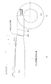
- FIG. 1 is a schematic view showing a region for measuring the concentration of Mo.
- FIG. 2 is a schematic view showing bending and bending back processing in the pipe circumferential direction.
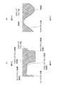
- FIG. 3 is a cross-sectional view of the fastening portion of the male screw and the female screw in the pipe axial direction (cross-sectional view parallel to the pipe axial direction).
- FIG. 3A is a trapezoidal screw
- FIG. 3B is a triangular screw.
- FIG. 4 is a cross-sectional view of a threaded joint in the pipe axis direction (cross-sectional view parallel to the pipe axis direction)
- FIG. 4A is a case of an API threaded joint
- FIG. 4B is a case of a premium joint.
- FIG. 4A is a case of an API threaded joint
- FIG. 4B is a case of a premium joint.
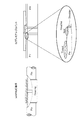
- FIG. 5 is a schematic view of the vicinity of the nose portion which is an extension portion of the pin
- FIG. 5A is a cut sectional view of the pin and the coupling fastening portion parallel to the pipe axis direction
- FIG. 5B is the screw tip of the pin. This is the torque shoulder part when the part is viewed from the front of the pin tip.
- the stainless seamless steel tube of the present invention is a stainless steel containing Cr: 11.5 to 35.0% and Mo: 0.5 to 6.0% in mass% and having ferrite and austenite, and has ferrite grains.
- the Mo concentration (mass%) of the boundary and / or the grain boundary of ferrite and austenite is 4.0 times or less of the Mo concentration (mass%) in the ferrite grain, or the Mo concentration (mass%) of the austenite grain boundary is It is characterized in that it is 4.0 times or less the Mo concentration in the austenite grains.
- Cr is an essential element that defines stainless steel, strengthens the passivation film, prevents the elution of iron, and suppresses the weight reduction and plate thickness reduction of the material.
- Mo is an important element for suppressing pitting corrosion, which is the most problematic when stress is applied in a corrosive environment.
- these two elements are solid-solved in steel, and these elements are evenly distributed in the steel, where these elements are thin on the material surface, that is, corrosion resistance. It is important not to create a weak place.
- Cr 11.5-35.0% Cr is the most important element that strengthens the passivation film of steel and enhances corrosion resistance. A Cr content of 11.5% or more is required to obtain a duplex structure and corrosion resistance as a duplex stainless seamless steel pipe. Increasing the amount of Cr is the most basic material for stabilizing the passivation film, and increasing the Cr concentration makes the passivation film stronger. Therefore, as the amount of Cr increases, it contributes to the improvement of corrosion resistance, but if Cr is contained in excess of 35.0%, the embrittled phase precipitates in the process of solidification from melting of steel and cracks occur in the entire solidified structure. , Subsequent molding to the tube becomes difficult. Therefore, the upper limit of Cr is set to 35.0%. From the viewpoint of ensuring both corrosion resistance and manufacturability, the preferable range of the amount of Cr is 20 to 28%.
- Mo 0.5-6.0% Mo increases the pitting corrosion resistance of steel depending on its content. Therefore, it is necessary to uniformly exist on the surface of the steel material exposed to the corrosive environment. On the other hand, if Mo is contained in excess, the embrittlement phase is precipitated when the molten steel is solidified, causing a large amount of cracks in the solidified structure, and the subsequent molding stability is greatly impaired. Therefore, the upper limit of the amount of Mo is 6.0%. In addition, Mo of 0.5% or more is required to maintain stable corrosion resistance in a sulfide environment. From the viewpoint of achieving both corrosion resistance and manufacturing stability required for duplex stainless seamless steel pipes, the Mo amount is preferably in the range of 1.0 to 5.0%.
- each phase of duplex stainless steel has different effects on corrosion resistance, and their presence in the steel in duplex exerts high corrosion resistance. Therefore, both the austenite phase and the ferrite phase must be present in the two-phase stainless steel, and the phase fraction thereof is also important from the viewpoint of corrosion resistance. Since the material of the present invention is a duplex stainless steel pipe used in applications requiring corrosion resistance, it is important to have an appropriate duplex fraction from the viewpoint of corrosion resistance.
- the ferrite phase fraction (volume fraction) in the duplex stainless steel pipe structure is 20% or more and 80% or less.
- volume fraction When used in an environment where more strict corrosion resistance is required, it is preferable to comply with ISO15156-3 and set the ferrite phase to 35 to 65%.
- the balance is preferably in the austenite phase.
- Mo concentration (mass%) of ferrite grain boundary and / or grain boundary of ferrite and austenite is 4.0 times or less of Mo concentration (mass%) in ferrite grain, or Mo concentration (mass%) of austenite grain boundary Is 4.0 times or less the Mo concentration (% by mass) in the austenite grains.
- the Mo concentration (mass%) of the ferrite grain boundaries and / or the grain boundaries of ferrite and austenite is 4.0 times or less the Mo concentration (mass%) in the ferrite grains.
- the Mo concentration (mass%) of the austenite grain boundaries needs to be 4.0 times or less the Mo concentration (mass%) in the austenite grains.
- the ferrite grain boundary is the boundary formed by adjacent ferrite and ferrite
- the ferrite and austenite grain boundary is the boundary formed by adjacent ferrite and austenite
- the austenite grain boundary is. It means the boundary formed by adjacent austenite and austenite.
- Mo concentration (mass%) of ferrite grain boundary and / or grain boundary of ferrite and austenite is 4.0 times or less of Mo concentration (mass%) in ferrite grain, or Mo concentration (mass%) of austenite grain boundary ) Is 4.0 times or less the Mo concentration (mass%) in the austenite grains, the corrosion resistance can be maintained in a good state. If the Mo concentration ratio is 2.5 times or less, the corrosion resistance is further enhanced. Further, in consideration of the variation in the concentration distribution of the elements, if these Mo concentration ratios are in the range of 0.8 to 2.0, excellent corrosion resistance can be stably obtained.
- the Mo concentration may be calculated excluding the data in the region of 0 to 50 nm from the edge of the grain boundary. For example, as shown in FIG. 1, regarding the measurement region of the Mo concentration in the grain, 100 nm from the grain boundary end or 200 nm from the grain boundary end in the lateral direction of the measurement region (in the direction perpendicular to the grain boundary, FIG. 1). (Corresponding to the horizontal direction inside).
- the Mo concentration is measured at a predetermined pitch in this predetermined region.
- There are various methods for quantitatively evaluating the concentration for example, a method for counting mass%. In that case, the value obtained by dividing the maximum value of mass% of Mo on the ferrite (phase) grain boundary (peak value, maximum value of mass%) by the average value of mass% of Mo in the ferrite (phase) grain (peak value). / Average value) may be calculated by defining it as the Mo segregation amount.
- Mo is not limited to STEM, and elemental analysis using, for example, a scanning electron microscope or a transmission electron microscope can also be used.
- the grain boundary in the present invention is a crystal azimuth angle of 15 ° or more.
- the crystal azimuth may be confirmed by STEM or TEM.
- it can be easily confirmed by crystal orientation analysis by the EBSD method (electron backscatter diffraction method).
- the stainless seamless steel pipe of the present invention is further mass%, C: 0.08% or less, Si: 1.0% or less, Mn: 10.0% or less, Ni: 15.0% or less, N: 0. It preferably contains less than 400%.
- the unit of the content of each element in the steel composition is "mass%", and is simply indicated by “%” unless otherwise specified.
- the upper limit of C is preferably 0.08% in order to obtain appropriate corrosion resistance. It is not necessary to set the lower limit in particular, but if the amount of C is too low, the decarburization cost at the time of melting increases, so it is preferably 0.005% or more.
- Si 1.0% or less A large amount of Si impairs workability and low temperature toughness. Therefore, the upper limit of Si is preferably 1.0%. Further, since Si has a deoxidizing effect on steel and it is effective to contain an appropriate amount in molten steel, it is preferably 0.01% or more. It is more preferable that Si is 0.2 to 0.8% from the viewpoint of suppressing side effects due to excessive remaining in the steel while sufficiently obtaining a deoxidizing action.
- Mn 10.0% or less Excessive content of Mn reduces cold toughness. Therefore, it is preferably 10.0% or less.
- Mn is a strong austenite phase-forming element and is cheaper than other austenite phase-forming elements. Furthermore, Mn is effective in detoxifying S, which is an impurity element mixed in molten steel, and has the effect of fixing S, which greatly deteriorates the corrosion resistance and toughness of steel, as MnS when added in a small amount. Therefore, it is preferable that Mn is contained in an amount of 0.01% or more. On the other hand, 2.0 to 8.0% is more preferable when it is desired to fully utilize Mn as an austenite phase-forming element from the viewpoint of achieving both cost reduction while paying attention to low temperature toughness. When low temperature toughness is required, it is more preferably less than 1.0%.
- Ni 15.0% or less
- Ni is the most expensive element among austenite phase-forming elements, and an increase in content leads to an increase in manufacturing costs. Therefore, it is not preferable to contain a large amount. Therefore, the upper limit is preferably 15.0%.
- Ni is a strong austenite phase-forming element and improves the low temperature toughness of steel. Therefore, when Mn, which is an inexpensive austenite phase-forming element, is used, it should be actively used when low temperature toughness becomes a problem, and the lower limit is preferably 0.5%. In the case of applications where low temperature toughness is not a problem, it is more preferable to add it in combination with other elements in the range of 0.5 to 5.0% or less. On the other hand, when low temperature toughness is required, active addition of Ni is effective, and the amount of Ni is more preferably in the range of 5 to 13%.
- N Less than 0.40% N itself is inexpensive, but excessive N addition requires special equipment and addition time, leading to an increase in manufacturing cost. Therefore, the upper limit is preferably less than 0.400%.
- N is a strong austenite phase-forming element and is inexpensive. In addition, it is an element useful for improving corrosion resistance and strength by being dissolved in steel.
- the range of N does not need to be particularly limited as long as the structure of the product can be made into an appropriate two-phase fraction in combination with other austenite phase-forming elements. However, if the amount of N is too low, a high degree of vacuum is required during melting and refining of steel, and the raw materials that can be used are limited. Therefore, it is preferably 0.010% or more.
- the present invention may further appropriately contain the elements described below, if necessary.
- W 6.0% or less
- Cu 4.0% or less
- V 1.0% or less
- Nb 1.0% or less
- W 6.0% or less W depends on the content like Mo This enhances pitting corrosion resistance, but if it is contained in excess, it impairs workability during hot working and impairs manufacturing stability. Therefore, when W is contained, the upper limit is 6.0%.
- the content of W of 0.1% or more is preferable for the reason of stabilizing the corrosion resistance of the duplex stainless seamless steel pipe. From the viewpoint of corrosion resistance and manufacturing stability required for duplex stainless seamless steel pipe, 1.0 to 5.0% is a more preferable range.
- Cu 4.0% or less
- Cu is a strong austenite phase-forming element and improves the corrosion resistance of steel. Therefore, the austenite phase-forming elements Mn and Ni should be actively utilized when the corrosion resistance is insufficient.
- Cu should be 4.0% or less.
- the lower limit of the content does not need to be specified, but a corrosion resistance effect can be obtained when the content is 0.1% or more. From the viewpoint of improving corrosion resistance and hot workability, 1.0 to 3.0% is a more preferable range.
- V 1.0% or less
- the addition of V is effective in improving the strength. Therefore, it can be used when higher strength is required.
- the strength improving effect can be obtained at 0.01% or more. Therefore, when it is contained, V is preferably 0.01% or more. Since V is an expensive element, 0.05 to 0.40% is a more preferable range from the viewpoint of the strength improving effect obtained by the addition and the cost.
- Nb 1.0% or less Excessive addition of Nb impairs low temperature toughness, so 1.0% or less is preferable.
- the addition of Nb is effective in improving the strength. Therefore, it can be used when higher strength is required.
- the strength improving effect can be obtained at 0.01% or more. Therefore, when it is contained, Nb is preferably 0.01% or more. Since Nb is an expensive element as well as V, 0.05 to 0.40% is a more preferable range from the viewpoint of the strength improving effect obtained by the addition and the cost.
- the present invention may further appropriately contain the elements described below, if necessary.
- Ti 0.30% or less
- Al 0.30% or less
- Ti 0.30% or less
- Ti can be used as appropriate when it is necessary to control the structure or adjust the chemical composition because it is possible to miniaturize the solidified structure and fix excess C and N. Therefore, when it is contained, such an effect can be obtained by setting Ti to 0.0001% or more. From the viewpoint of controlling the structure and chemical composition and obtaining product characteristics, 0.0010 to 0.10% is more preferable.
- Al 0.30% or less If a large amount of Al remains in the product, the toughness will be impaired. Therefore, when Al is contained, it is preferably 0.30% or less. In addition, the addition of Al is effective as a deoxidizing material during refining. In order to obtain this effect, when Al is contained, it may be 0.01% or more.
- the present invention may further appropriately contain the elements described below, if necessary.
- the upper limit of the addition amount is preferably 0.010% for each of B, Zr, Ca, and REM.
- B, Zr, Ca, and REM when a very small amount of B, Zr, Ca, and REM is added, the bonding force at the grain boundaries is improved, and the form of oxides on the surface is changed to improve hot processability and moldability.
- Duplex stainless seamless steel pipes are generally difficult-to-process materials, so rolling flaws and shape defects due to the amount of processing and processing form are likely to occur, but under molding conditions that cause such problems. These elements are effective. It is not necessary to set a lower limit for the amount of addition, but when B, Zr, Ca, and REM are contained, the effect of improving workability and moldability can be obtained by setting each to 0.0001% or more. If the amount of Ta added is too large, the alloy cost will increase. Therefore, when Ta is contained, the upper limit is preferably 0.30%. Further, when a small amount of Ta is added, the transformation to the embrittled phase is suppressed, and the hot workability and the corrosion resistance are improved at the same time.
- Ta is effective when the embrittled phase stays in a stable temperature range for a long time due to hot working or subsequent cooling. Therefore, when Ta is contained, it should be 0.0001% or more. Further, as the amount of Sb and Sn added increases, the moldability decreases. Therefore, when Sb and Sn are added, the upper limit is preferably 0.30%. Further, when a small amount of Sb and Sn is added, the corrosion resistance is improved. Therefore, when Sb and Sn are added, the content should be 0.0003% or more.
- the rest is Fe and unavoidable impurities.
- the tensile yield strength in the pipe axial direction is 689 MPa or more. Since two-phase stainless steel usually contains a soft austenite phase in its structure, the axial tensile yield strength does not reach 689 MPa in the state of solid solution heat treatment. Therefore, a tensile yield strength in the pipe axial direction of 689 MPa or more can be obtained by dislocation strengthening by the above-mentioned cold working (bending and bending back processing in the pipe circumferential direction). The higher the tensile yield strength in the pipe axial direction, the thinner the pipe can be designed for a well design for mining, which is advantageous in terms of cost.
- the tensile yield strength in the pipe axial direction be used within the range of 1033.5 MPa at the highest.
- the ratio of the axial compressive yield strength to the tubular axial tensile yield strength is 0.85 to 1.15.
- the ratio of the compression yield strength in the tube circumferential direction to the tensile yield strength in the tube axial direction is 0.85 or more.
- the depth of a well that can be mined depends on the axial tensile yield stress of the pipe when the wall thickness of the pipe is the same.
- the ratio of the compression yield strength in the circumferential direction to the tensile yield stress in the pipe axial direction is preferably 0.85 or more.
- the compression yield strength in the pipe circumferential direction is larger than the tensile yield strength in the pipe axis direction, but the ratio of the compression yield strength in the pipe circumference direction to the tensile yield stress in the pipe axis direction is usually 1.50 at most. Saturates with degree.
- this strength ratio is more preferably in the range of 0.85 to 1.25.
- the aspect ratio of the austenite grains separated by a crystal azimuth angle difference of 15 ° or more in the wall thickness direction in the tube axis direction is 9 or less. Is preferable. Further, it is preferable that the austenite grains having an aspect ratio of 9 or less have an area fraction of 50% or more.
- the stainless steel of the present invention is adjusted to an appropriate ferrite phase fraction by the solid solution heat treatment temperature.
- the structure inside the remaining austenite phase, the structure has a plurality of crystal grains separated by an azimuth angle of 15 ° or more due to recrystallization during hot working or heat treatment. As a result, the aspect ratio of the austenite grains becomes small.
- the stainless seamless steel pipe in this state does not have the pipe axial tensile yield strength required for oil wells or geothermal wells, while the pipe axial compressive yield strength / pipe axial tensile yield strength is also close to 1. It becomes.
- conventional stretching processing cold drawing rolling, cold Pilger rolling
- yield strength / axial tensile yield strength and aspect ratio of austenite grains There is a change in yield strength / axial tensile yield strength and aspect ratio of austenite grains. That is, the aspect ratio of the austenite grains and the compression yield strength in the tube axial direction / the tensile yield strength in the tube axial direction are closely related.
- the yield strength is improved in the direction in which the austenite grains having a wall thickness cross section in the pipe axis direction (thickness direction of the pipe cross section parallel to the pipe axis direction) are stretched before and after processing, but instead.
- the yield strength decreases due to the bow singer effect, and the difference between the axial compression yield strength and the tubular axial tensile yield strength increases. From this, if cold working is selected to control the aspect ratio of austenite grains before and after machining to be small, as a result, the strength anisotropy in the pipe axis direction is small, and the strength characteristics of the threaded joint are excellent. Steel pipes can be obtained.
- the aspect ratio of the austenite grains is 9 or less, a stable steel pipe with little strength anisotropy can be obtained. Further, if the austenite grains having an aspect ratio of 9 or less have an area fraction of 50% or more, a steel pipe having less anisotropy of strength can be stably obtained. By setting the aspect ratio to 5 or less, a more stable steel pipe with less anisotropy of strength can be obtained. The smaller the aspect ratio, the more the anisotropy of the strength can be reduced. Therefore, the lower limit is not particularly limited, and the closer to 1 is preferable.
- the aspect ratio of the austenite grains is the long side when the grains with a crystal orientation angle of 15 ° or more in the austenite phase are observed by crystal orientation analysis of the thick cross section in the tube axis direction and the grains are housed in a rectangular frame. It is calculated by the ratio of the short side. Since austenite particles having a small particle size have a large measurement error, an error may occur in the aspect ratio if austenite particles having a small particle size are included. Therefore, the austenite grain for which the aspect ratio is measured preferably has a diameter of 10 ⁇ m or more when a perfect circle having the same area is drawn using the measured grain area.
- the aspect ratio of the ferrite phase is not particularly limited. The reason is that the austenite phase has a lower yield strength and easily affects the Bauschinger effect after processing.
- the threaded joint consists of a pin with a male thread and a box with a female thread.
- screw joints standard screw joints specified in the API (American Petroleum Association) standard and high-performance special screw joints called premium joints that have not only screw parts but also metal touch seal parts and torque shoulder parts.
- the threaded portion is generally designed so that a contact surface pressure is generated in the radial direction, and for example, a tapered screw is used. With the surface pressure in the radial direction, the pin (male screw side) is reduced in diameter and extends in the pipe axis direction, and the box (female screw side) is expanded and deformed and contracted in the pipe axis direction. Contact surface pressure is generated.
- a compressive stress in the pipe axial direction is generated in the thread according to the fastening force. Therefore, the axial compressive yield strength that can withstand this compressive stress is important. Since a large axial compressive stress is generated in the torque shoulder portion in the premium joint, a material having a high axial compressive yield strength is also important for preventing plastic deformation of the torque shoulder portion.
- the stainless seamless steel pipe of the present invention Since the stainless seamless steel pipe of the present invention has excellent compression resistance, it is a screw joint that is directly connected to another steel pipe (integral type) or a screw that is connected via a coupling (T & C type). It can be used for fittings. At the tightening part of the screw, when tightening, axial tension and compressive stress are generated due to bending deformation after tightening.
- a threaded joint capable of maintaining high corrosion resistance and threaded joint performance.
- FIG. 3 is a cross-sectional view of the fastening portion of the male screw and the female screw in the pipe axis direction (cross-sectional view parallel to the pipe axis direction), and is a schematic view showing the position of the radius of curvature R of the corner portion at the fastening portion of the screw.
- FIG. 3A shows a trapezoidal screw
- FIG. 3B shows a triangular screw.
- at least one pipe end is provided with a male or female screw fastening portion, and the radius of curvature of the corner portion formed by the flank surface and the bottom surface of the thread valley of the fastening portion is 0.2 mm or more. preferable.
- the radius of curvature of the corner portion R formed by the flank surface and the bottom surface of the screw valley where the male screw and the female screw come into contact with each other by fastening and pressure is generated by fastening is determined.
- the thickness is 0.2 mm or more, the fatigue characteristics can be improved while maintaining high corrosion resistance.
- the thread slope on the side of the male screw (pin) near the pipe end is called the stubing flank surface, and the thread slope on the side far from the pipe end is called the road flank surface.
- the thread slope facing the stubing flank surface of the pin is called a stubing flank surface
- the thread slope facing the load flank surface of the pin is called a road flank surface.
- FIG. 4 is a cross-sectional view of a threaded joint in the pipe axis direction (cross-sectional view parallel to the pipe axis direction), FIG. 4A is a case of an API threaded joint, and FIG. 4B is a case of a premium joint.
- a screw joint consisting of only screw parts such as API screw joints, maximum surface pressure is generated at both ends of the screw part when the screw is fastened, and the screw part on the pin tip side comes into contact with the stubing flank surface after the pin. The threaded portion on the end side comes into contact with the road flank surface.
- the corner portion R is preferably in the range of 0.2 to 3.0 mm.
- the radius of curvature is such that the corner portion R occupies the length in the direction), and the radius of curvature of the corner portion R is designed to be 0.2 mm or more.
- FIG. 4B is a schematic view of a premium joint including not only a screw portion but also a metal touch seal portion and a torque shoulder portion.
- the tightness of the pipe fastened by the metal touch seal portion (Sea in FIG. 4B) shown in FIG. 4B is guaranteed.
- the torque shoulder portion acts as a stopper during tightening and plays an important role in ensuring a stable tightening position, but has a high compressive stress during tightening. Occurs. If the torque shoulder part is deformed due to high compressive stress, the high airtightness is impaired, or the inner diameter is reduced due to the deformation toward the inner diameter side, which causes a problem. It becomes necessary to improve the compressive strength, and it is not possible to design a thin-walled steel pipe, or the material is wasted due to the excess wall thickness.
- the tightening torque value (the value of the torque while tightening the screw) is checked, and the sealed torque value (the torque value that indicates a sealed state when a certain standard is exceeded by tightening). Therefore, from the torque value during tightening), the torque shoulder part does not deform (the screw tip deforms when the torque value exceeds a certain standard, so the torque does not exceed this standard.
- the tightening is performed by managing the torque value within the range from the sealed torque value to the torque value at which the torque shoulder portion is not deformed, with the value) as the upper limit.
- the present invention which is excellent in the compression yield strength in the pipe axis direction of the pipe, it is possible to suppress the deformation of the torque shoulder portion while maintaining high corrosion resistance.
- the tip thickness of the torque shoulder portion of the male screw is increased, the nose rigidity becomes too high and there is a problem of seizure during tightening. Therefore, the preferable range is 25 to 60%. It is preferable to design the nose portion so as to further increase the compressive strength of the torque shoulder portion because higher torque performance (the torque value that does not deform becomes higher and a higher tightening torque can be given) can be realized.
- FIG. ) (B) As a schematic view of the vicinity of the nose portion which is an extension portion of the pin, FIG. ) (B), respectively.
- the ratio x / L to the nose length L which is the unthreaded part of the pin tip when the seal point position from the pipe end is x, should be 0.01 or more and 0.1 or less. Is good.
- the substantial sectional area of the shoulder portion (the cross-sectional area of the shoulder portion: ⁇ / 4 ⁇ (Ds1 2 -Ds0 2)) elevated high torque resistance is obtained.
- the nose length is preferably 0.5 inch or less.
- the sealing property indicating airtightness is also important as a characteristic of the threaded portion, and it is preferable to satisfy the compression ratio of 85% or more shown in the sealing test of ISO 13679: 2019.
- the ratio x / to the nose length L when the nose length of the pin tip without screw is 0.3 inch or more and the seal point position from the pipe end is x. It is preferable that L is 0.2 or more and 0.5 or less.
- the nose length is 1.0 inch or less. It should be noted that a design with a long nose length could not be realized because the conventional duplex stainless steel having a low compression yield strength cannot withstand the design in which the tip of the nose is inevitably thin.
- a steel material having the above duplex stainless steel composition is produced.
- Various melting processes can be applied to the melting of duplex stainless steel, and there are no restrictions.
- a vacuum melting furnace or an atmospheric melting furnace can be used when iron scrap or a mass of each element is electrically melted for production.
- an Ar-O 2 mixed gas bottom-blown decarburization furnace or a vacuum decarburization furnace can be used.
- the melted material is solidified by static casting or continuous casting to form an ingot or slab, and then hot-rolled or forged to form a round billet shape to form a steel material.
- Hot forming is performed to make a round billet into a hollow tube.
- any method such as the Mannesmann method or the extrusion tube manufacturing method can be used.
- an elongator, an assell mill, a mandrel mill, a plug mill, a sizer, a stretch reducer or the like, which is a hot rolling process for thinning and standardizing the outer diameter of a hollow pipe, may be used.
- the solid solution heat treatment temperature is preferably 1000 ° C. or higher, and preferably 1200 ° C. or lower.
- quenching is performed to maintain the solid solution state, but cooling with compressed air and various refrigerants such as mist, oil, and water can be used. If the material temperature after hot rolling is the same as the solid solution heat treatment temperature of the material, rapid cooling eliminates the need for the subsequent solid solution heat treatment.
- the strength of the pipe is increased by utilizing the dislocation strengthening by various processing.
- the strength grade of the duplex stainless seamless steel pipe after increasing the strength is determined by the tensile yield strength in the axial direction of the pipe.
- the strength of the pipe is increased by bending and bending back in the circumferential direction of the pipe.
- cold rolling methods for oil well and gas well mining cold drawing rolling and cold Pilger rolling, both of which are pipe shafts. It is possible to increase the strength in the direction. In these methods, the reduction rate and the outer diameter change rate are mainly changed to increase the strength to the required strength grade.
- cold drawing rolling and cold Pilger rolling are rolling forms in which the outer diameter and wall thickness of the pipe are reduced and the amount is greatly extended in the longitudinal direction of the pipe shaft.
- the cold working method of the present invention is a new method that utilizes dislocation strengthening by bending and bending back in the pipe circumferential direction.
- This processing method will be described with reference to the drawings.
- This method is different from cold drawing rolling and cold Pilger rolling in which strain due to rolling occurs in the longitudinal direction of the pipe axis, and as shown in FIG. 2, the strain is after bending due to flattening of the pipe (first flattening). , It is given by the bending back processing (second flat processing) when returning to a perfect circle again.
- the strain amount is adjusted by utilizing repeated bending and bending back and changes in the bending amount without significantly changing the initial steel pipe shape.
- the conventional cold rolling method utilizes the elongation strain in the pipe axial direction, whereas the bending strain in the pipe circumferential direction is used.
- strain in the pipe axial direction is suppressed, so that the Bauschinger effect in the pipe axial direction that occurs in the conventional cold rolling method does not occur in principle. Therefore, low-temperature heat treatment after cold working is not required, and the "state in which the corrosion-resistant element is solid-solved in steel" after the solid solution heat treatment required for good corrosion resistance can be obtained, and the strength of the threaded portion is good. It is possible to achieve both the high axial compression yield strength required for the characteristics.
- FIGS. 2 (a) and 2 (b) are cross-sectional views when the tool contact portions are at two locations
- FIG. 2 (c) is a cross-sectional view when the tool contact portions are at three locations.
- the thick arrow in FIG. 2 indicates the direction in which a force is applied when flattening the steel pipe.
- the tool is moved so as to rotate the steel pipe or the position of the tool is shifted so that the tool comes into contact with the portion where the first flattening is not performed. It is sufficient to devise such as slack (the shaded part in FIG. 2 indicates the first flattened part).
- rolls may be used, and if the steel pipe is flattened and rotated between two or more rolls arranged in the circumferential direction of the steel pipe, it is easily repeatedly bent and bent back. It is possible to give strain. Further, if the rotation axis of the roll is tilted within 90 ° with respect to the rotation axis of the pipe, the steel pipe advances in the direction of the rotation axis of the pipe while undergoing flattening, so that the processing can be easily continued. Further, in the continuous processing using this roll, for example, if the roll interval is appropriately changed so as to change the flatness amount with respect to the progress of the steel pipe, the first and second steel pipes can be easily processed.
- Curvature (flatness) can be changed. Therefore, by changing the roll interval, the movement path of the neutral line can be changed to homogenize the strain in the wall thickness direction. Further, the same effect can be obtained by changing the flatness amount by changing the roll diameter instead of the roll interval. Moreover, you may combine these. Although it is complicated in terms of equipment, if the number of rolls is 3 or more, the runout of the pipe during processing can be suppressed, and stable processing becomes possible.
- the processing amount is the minimum radius at the time of bending with respect to the initial steel pipe diameter Di, that is, the flatness generated under the outer diameter reduction from two places, or three. It is easy to manage by using the minimum diameter Dmin during deformation calculated by twice the minimum radius portion from the center of the triangular steel pipe generated by bending from a location. Further, since the machining amount is also affected by the initial wall thickness ti with respect to the initial outer diameter Di of the steel pipe, it is preferable to also use the management using ti / Di calculated from this value. These parameters can be determined centrally once the product size and manufacturing equipment are determined.
- the range of stable manufacturing is expanded, and the strength ratio of compression yield strength in the tube axis direction / tensile yield strength in the tube axis direction is set to 0 in the range of the index of 0.5 to 3.0. It can be manufactured at .85 to 1.15. When the index is in the range of 0.7 to 2.0, extremely stable production is possible.
- the material to be processed in order to maintain the "state in which the corrosion-resistant element is solid-solved in the steel" and suppress the segregation of Mo, is to be bent and returned in the pipe circumferential direction in the cold.
- the maximum temperature reached is 300 ° C. or less, and the holding time at this maximum temperature is 15 minutes or less.
- the processing speed deformation speed when deforming into a flat shape
- the maximum temperature reached can be appropriately controlled.
- the surface treatment temperature at the time of plating is set so that the maximum temperature of the material to be processed is 300 ° C. or less and the holding time at this maximum temperature is 15 minutes or less. It may be controlled as appropriate.
- the radius of curvature of the corner portion R formed by the bottom surface of the thread valley and the flank surface in the pipe shaft cross section (cross section parallel to the pipe axis direction) of the threaded joint portion may be designed so that the thickness is 0.2 mm or more.
- the screw shape may be provided by cutting or rolling, and cutting is preferable in order to stably obtain the shape of the corner portion R.
- the stainless seamless steel pipe of the present invention has a high compressive yield strength in the pipe axial direction, if the cross-sectional area of the shoulder portion is 25% or more of the cross-sectional area of the pin element pipe, it can exhibit a function without a problem as a joint. Is possible.
- the nose length of the pin tip without screw shown in FIG. 5 is 0.2 inches. It is preferable that the ratio x / L to the nose length L is 0.01 or more and 0.1 or less when the seal point position from the pipe end is x. On the other hand, in order to realize a highly airtight metal touch seal portion, the nose length of the pin tip without screw is set to 0.3 inch or more and 1.0 inch or less, and the seal point position from the pipe end is set.
- the ratio x / L to the nose length L when x is preferably 0.2 or more and 0.5 or less.
- the stainless seamless steel pipe of the present invention can be obtained.
- the cold working method by bending and bending back and the low temperature heat treatment are not performed, so that the deterioration of the corrosion resistance performance due to the segregation of Mo is suppressed, and the compression yield strength in the pipe axial direction / the tensile strength in the pipe axial direction is suppressed. It is possible to provide a duplex stainless seamless steel pipe having a yield strength ratio of 0.85 to 1.15 and having excellent thread strength characteristics required for oil and gas well applications.
- the round billet is inserted into the heating furnace again, held at a high temperature of 1200 ° C. or higher, and then subjected to perforation rolling and stretched constant diameter rolling.
- the size is not limited to the above, and any size is applicable as long as it can be manufactured as a seamless steel pipe.
- the main size may be a pin of ⁇ 60.3 to 244.5 mm from the tubing size to the production casing size and the corresponding coupling tube size. Then, the mother tube was subjected to a solid solution heat treatment in a temperature range of 1000 to 1150 ° C.
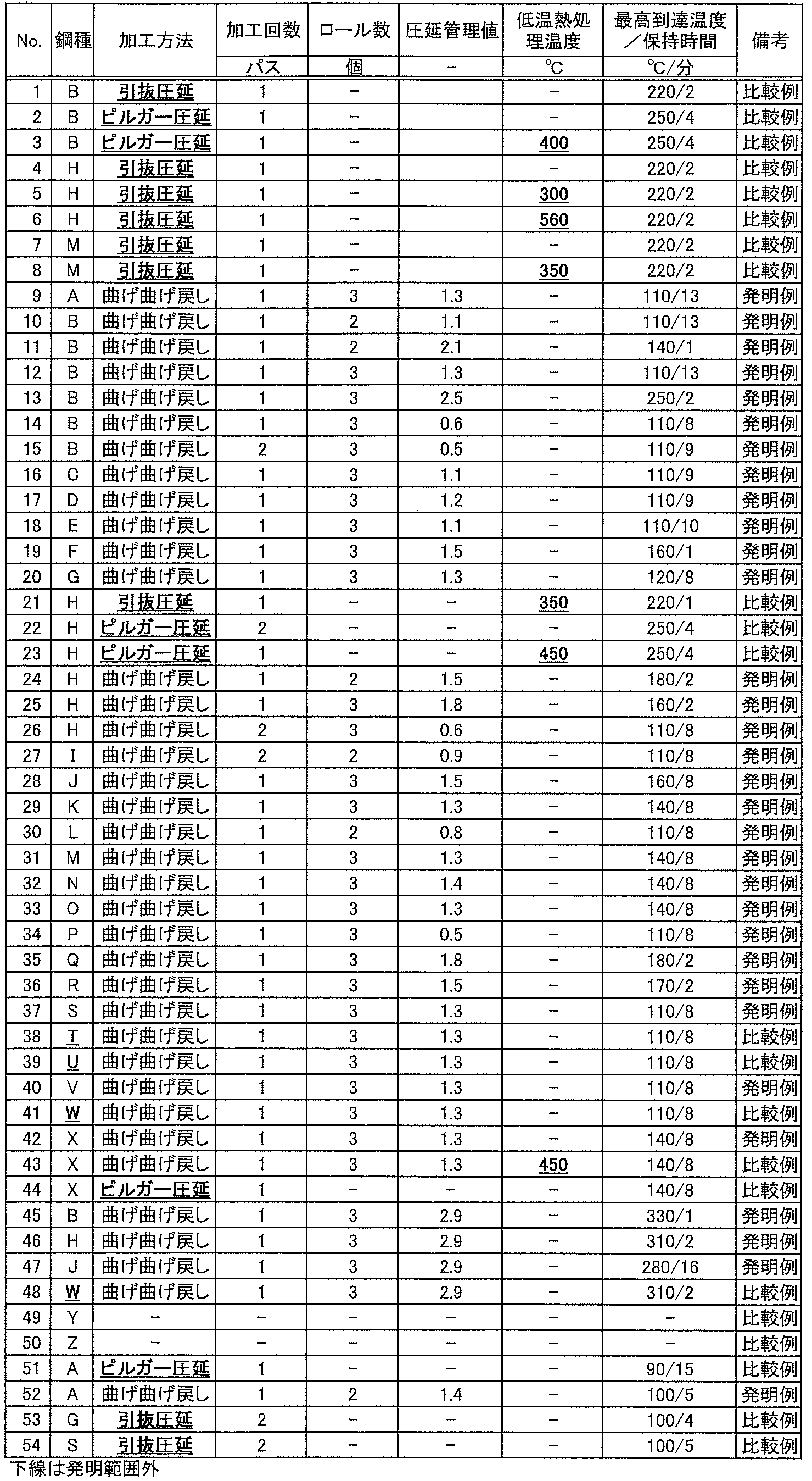
- cold working was performed.
- drawing rolling and bilger rolling were also performed.
- a value obtained by multiplying 100 [%] by the initial wall thickness ti and ti / Di calculated by the initial outer diameter Di was used as the rolling control value.
- the condition of performing cold processing twice under the same processing conditions was also carried out. Further, some of them were subjected to low temperature heat treatment at the temperatures shown in Table 2 after cold working. The maximum temperature reached of the work material was controlled by measuring the actual temperature at the time of manufacturing the steel pipe of the example.
- thinning and stretching rolling was performed at a wall thickness reduction rate of 20% using a raw pipe having an outer diameter of ⁇ 139.7 mm and a wall thickness of 12 mm.
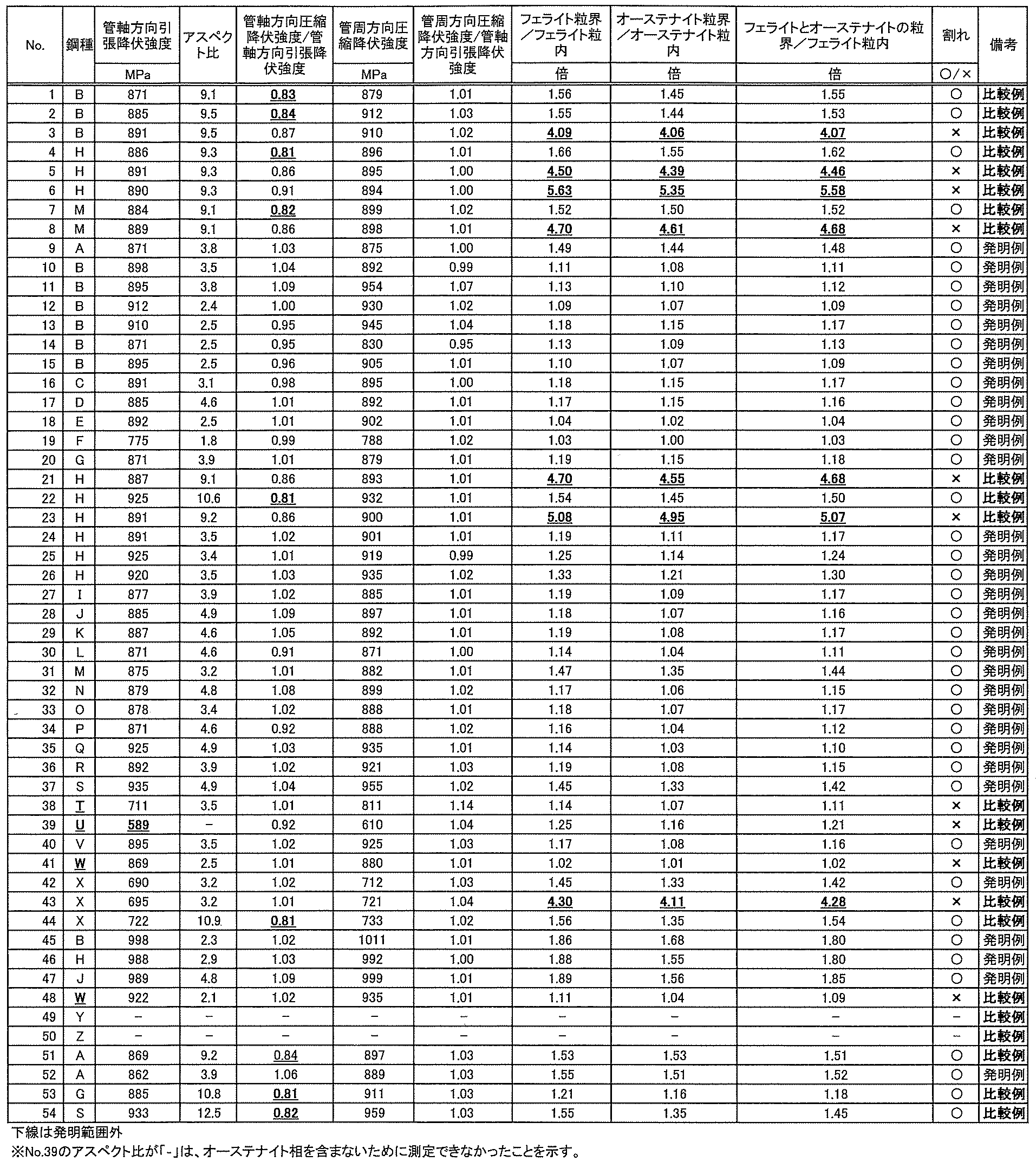
- the tensile yield strength and compressive yield strength in the pipe axial direction, and the compressive yield strength in the pipe circumferential direction were subjected to a round bar tensile test with a parallel part diameter of 4 to 6 mm and a columnar compression test at the center of the pipe wall thickness.
- the strength is measured at a cross-head speed of 1 mm / min for both tensile and compression, and the tensile yield strength in the tube axis direction and the compression yield strength in the tube axis direction / the tensile yield strength in the tube axis direction and the compression yield strength in the tube circumference direction /
- the tensile yield strength in the tube axis direction was calculated.
- Corrosive environment is aqueous simulating the oil wells in mining (20% NaCl + 0.5% CH 3 COOH + CH 3 3.0 added to pH of H 2 S gas at a pressure of 0.01 ⁇ 0.10 MPa in an aqueous solution of COONa ⁇ 4
- the temperature was adjusted to 5.5 and the test temperature was 25 ° C.).
- a 4-point bending test piece with a thickness of 4 mm (thickness) from the center of the wall thickness or a round bar tensile test piece with a diameter of ⁇ 8 mm is cut out from the center of the wall thickness so that stress can be applied in the longitudinal direction of the pipe axis.
- a stress of 90% was applied to the tensile yield strength and the mixture was immersed in the above aqueous solution.
- To evaluate the corrosion status after immersing the test piece in a corroded aqueous solution for 720 hours in a stressed state, take out the test piece and immediately visually inspect the stressed surface of the test piece. Those that were given were evaluated as x.
- the concentration (% by mass) of Mo was set to 0 in the region of (width from the end of ferrite grain boundary or austenite grain boundary to 150 nm) ⁇ (length of 2 nm in the direction parallel to the grain boundary). It was measured at a pitch of 2 nm.
- the Mo concentration (mass%) was measured at a pitch of 0.2 nm (the measurement region is the hatching portion position corresponding to the grain boundary in FIG. 1 within the range corresponding to the grain boundary). . Use the peak value for the value.).
- the maximum value (peak value) in the measurement region was used. Further, for the Mo concentration (mass%) in each grain (in the ferrite grain and in the austenite grain), the average value in the measurement region was used. The value obtained by dividing each maximum value by each average value (peak value / average value), that is, the Mo concentration at the ferrite grain boundary (ferric grain boundary / within the ferrite grain) with respect to the Mo concentration in the ferrite grain, and the Mo concentration in the ferrite grain.
- the Mo concentration of the grain boundaries of ferrite and austenite (in the grain boundary of ferrite and austenite / in the ferrite grain) and the Mo concentration of the austenite grain boundary (in the grain boundary of austenite / in the austenite grain) with respect to the Mo concentration in the austenite grain were determined. ..
- the average value in the ferrite grains or the austenite grains was calculated excluding the data in the region of 0 to 50 nm from the ferrite grain boundary or the end of the austenite grain boundary.
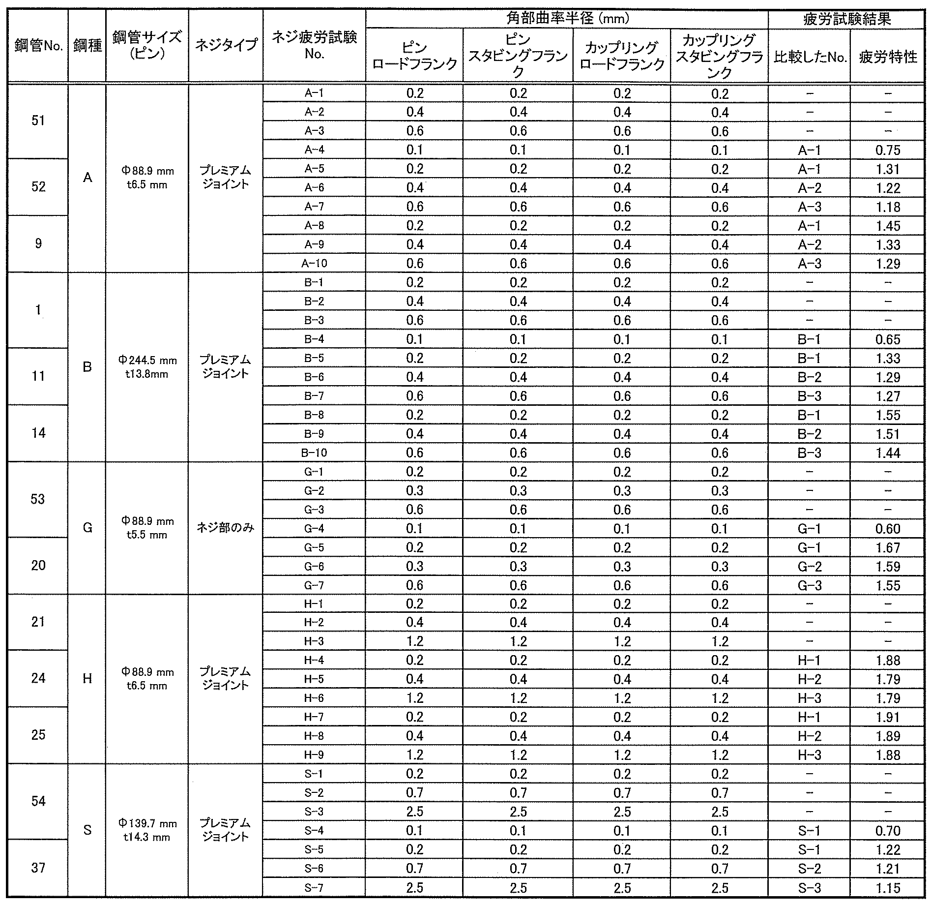
- a trapezoidal threaded portion is formed by machining at the end of the two-phase stainless steel pipe obtained in Example 1 (see FIG. 3A), and after fastening the two steel pipes with screws, the axial tension of the steel pipe is applied.
- a fatigue test was conducted on a threaded portion that was rotated with both pipe ends eccentric by 3 to 10% according to the yield strength.
- the corner portion R which is the stress concentration portion, is changed as shown in Table 4, and the number of rotations until the screw thread breaks due to the fatigue crack in the stress concentration portion and the growth of the fatigue crack is investigated.
- pins (steel pipe sizes) having an outer diameter of ⁇ 88.9 mm and wall thicknesses of t5.5 and 6.5 mm and corresponding cups.
- a threaded joint consisting of a ring
- a threaded joint consisting of a pin with an outer diameter of ⁇ 244.5 mm and a wall thickness of t13.8 mm and a corresponding coupling
- a pin with an outer diameter of ⁇ 139.7 mm and a wall thickness of t14.3 mm and a corresponding coupling.
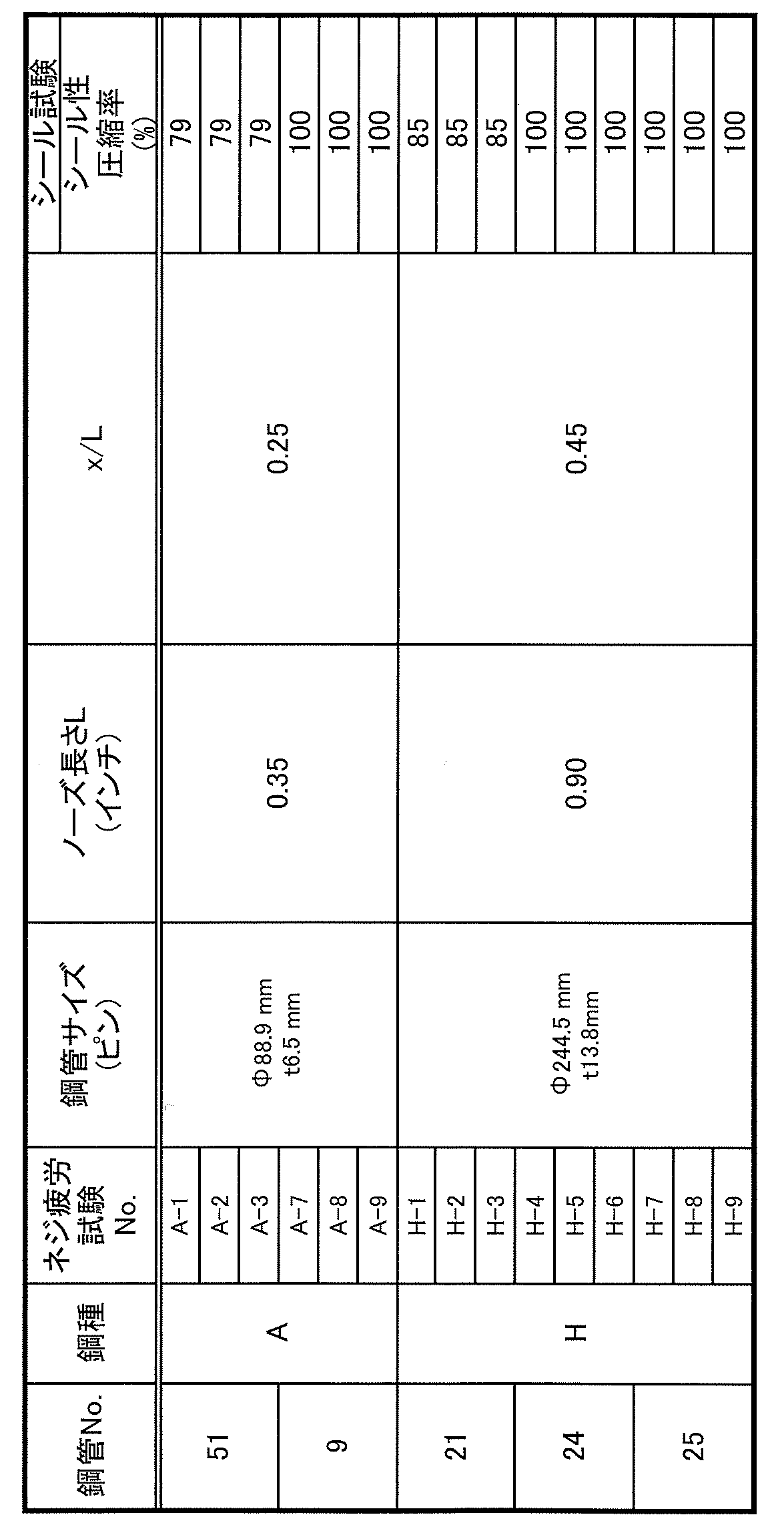
- a tightening test (Yield torque evaluation test) was performed on a threaded joint (premium joint) composed of a pin having an outer diameter of ⁇ 88.9 mm, a wall thickness of 6.5 mm, and a tensile strength of 689 MPa and a corresponding coupling.
- a screw joint composed of a pin having an outer diameter of ⁇ 88.9 mm, a wall thickness of 6.5 mm, and a tensile strength of 689 MPa and a corresponding coupling, an outer diameter of ⁇ 244.5 mm, a wall thickness of t13.
- a seal test was performed on a threaded joint (premium joint) consisting of an 8 mm pin and a corresponding coupling.
- the first high-performance screw joint there is a high torque screw joint that can secure the sealing performance even if a high tightening torque is applied.
- High torque can be obtained by adopting a stainless seamless steel pipe having high compressive strength as in the present invention for a threaded joint.
- the design of the threaded joint it is possible to realize even higher torque.
- the ratio x / L to the nose length L when the nose length of the pin tip without screw is 0.2 inch or more and 0.5 inch or less and the seal point position from the pipe end is x. Is designed to be 0.01 or more and 0.1 or less.
- the nose length of the threadless part at the tip of the pin should be 0.3 inches or more and 1.0 inches or less, and from the pipe end. It is preferable that the ratio x / L to the nose length L when the seal point position of is x is 0.2 or more and 0.5 or less. If the nose length is lengthened and the seal point is separated from the pipe end as described above, the cross-sectional area of the shoulder portion becomes small, and there is a possibility that the cross-sectional area of the conventional material will cause the Yield problem and design will not be possible. Is high. This problem became remarkable with a thin wall, and it was not feasible with a wall thickness of 6.5 mm.
- the stainless seamless steel pipe of the present invention has high compressive strength, the problem of Yield can be avoided if the cross-sectional area of the shoulder portion can be secured at 20%, and it is possible to achieve both the secure cross-sectional area of the shoulder portion and the design of high sealing performance.
- rice field As shown in Table 6, it was confirmed that when the tube axial compressive yield strength / tube axial tensile yield strength was 0.85 or more, the seal test passed at a compressibility of 85% under a test load of ISO 13679: 2019. It was confirmed that if the compression yield strength in the tube axial direction / tensile yield strength in the tube axial direction was 1.0 or more, the seal test was passed at a compressibility of 100%.
Landscapes
- Chemical & Material Sciences (AREA)
- Engineering & Computer Science (AREA)
- Materials Engineering (AREA)
- Mechanical Engineering (AREA)
- Metallurgy (AREA)
- Organic Chemistry (AREA)
- Crystallography & Structural Chemistry (AREA)
- Physics & Mathematics (AREA)
- Thermal Sciences (AREA)
- Manufacturing & Machinery (AREA)
- Heat Treatment Of Steel (AREA)
- Heat Treatment Of Articles (AREA)
Abstract
Description
[1]質量%で、Cr:11.5~35.0%、Mo:0.5~6.0%を含有する成分組成であり、フェライトとオーステナイトを有するステンレス鋼であり、フェライト粒界および/またはフェライトとオーステナイトの粒界のMo濃度(質量%)がフェライト粒内のMo濃度(質量%)に対して4.0倍以下、または、オーステナイト粒界のMo濃度(質量%)がオーステナイト粒内のMo濃度(質量%)に対して4.0倍以下であり、管軸方向引張降伏強度が689MPa以上であり、かつ管軸方向圧縮降伏強度/管軸方向引張降伏強度が0.85~1.15であるステンレス継目無鋼管。
[2]管周方向圧縮降伏強度/管軸方向引張降伏強度が0.85以上である[1]に記載のステンレス継目無鋼管。
[3]さらに質量%で、C:0.08%以下、Si:1.0%以下、Mn:10.0%以下、Ni:15.0%以下、N:0.400%未満を含有し、残部がFeおよび不可避的不純物からなる成分組成である[1]または[2]に記載のステンレス継目無鋼管。
[4]さらに質量%で、W:6.0%以下、Cu:4.0%以下、V:1.0%以下、Nb:1.0%以下のうちから選ばれた1種または2種以上を含有する[1]~[3]のいずれかに記載のステンレス継目無鋼管。
[5]さらに質量%で、Ti:0.30%以下、Al:0.30%以下のうちから選ばれた1種または2種を含有する[1]~[4]のいずれかに記載のステンレス継目無鋼管。
[6]さらに質量%で、B:0.010%以下、Zr:0.010%以下、Ca:0.010%以下、Ta:0.30%以下、Sb:0.30%以下、Sn:0.30%以下、REM:0.010%以下のうちから選ばれた1種または2種以上を含有する[1]~[5]のいずれかに記載のステンレス継目無鋼管。
[7][1]~[6]のいずれかに記載のステンレス継目無鋼管であって、少なくとも一方の管端部に雄ネジまたは雌ネジの締結部を備え、前記締結部のフランク面とネジ谷底面で形成される角部の曲率半径が0.2mm以上であるステンレス継目無鋼管。
[8][7]に記載のステンレス継目無鋼管であって、少なくとも一方の管端部に雄ネジまたは雌ネジの締結部を備え、前記締結部にメタルタッチシール部とトルクショルダ部を備えるステンレス継目無鋼管。
[9][1]~[8]のいずれかに記載のステンレス継目無鋼管の製造方法であって、固溶体化熱処理後に冷間で管周方向の曲げ曲げ戻し加工を行うステンレス継目無鋼管の製造方法。
[10]冷間で管周方向の曲げ曲げ戻し加工をする際、被加工材の最高到達温度を300℃以下、前記最高到達温度での保持時間を15分以下とする[9]に記載のステンレス継目無鋼管の製造方法。
Crは鋼の不動態被膜を強固にし、耐食性能を高めるもっとも重要な元素である。二相ステンレス継目無鋼管としての二相組織と耐食性能を得るには11.5%以上のCr量が必要となる。Cr量の増加は不働態被膜を安定化させる最も基本的な材料であり、Cr濃度が増加すると不働態被膜はより強固になる。このため、Cr量が増加するほど耐食性向上に寄与するが、35.0%を超えてCrを含有すると、鋼の溶解から凝固する過程で脆化相が析出し凝固組織全体に割れが発生してしまい、その後の管への成形加工が困難になる。そのためCrの上限は35.0%とする。なお、耐食性の確保と製造性の両立の観点から、好ましいCr量の範囲は20~28%である。
Moは含有量に応じて鋼の耐孔食性を高める。そのため腐食環境に曝される鋼材表面に均一に存在させる必要がある。一方で、過剰にMoを含有すると、溶鋼が凝固する時に脆化相が析出し、凝固組織中に多量の割れを発生させ、その後の成形安定性を大きく損なう。そのため、Mo量の上限は6.0%とする。また、硫化物環境で安定した耐食性を維持するために、Moは0.5%以上が必要である。なお、二相ステンレス継目無鋼管に必要とされる耐食性と製造安定性の両立の観点から、Mo量は、1.0~5.0%が好適な範囲である。
次に耐食性に重要な製品中のフェライト、オーステナイト相の適切な相分率について説明する。二相ステンレス鋼の各相は耐腐食性に関して異なる作用を有しており、それらが二相で鋼中に存在することで高い耐食性を発揮する。そのため二相ステンレス鋼中にはオーステナイト相とフェライト相の両方が存在していなければならず、さらにその相分率も耐食性能の観点で重要である。本発明の材料は耐食性能が必要な用途で使用される二相ステンレス鋼管であるため、耐食性の観点から適切な二相分率状態にすることが重要である。そのため、本発明における適切な二相分率状態としては、二相ステンレス鋼管組織中の少なくともフェライト相分率(体積分率)を20%以上80%以下とすることが好ましい。また、より耐食性が厳しく求められる環境で利用される際はISO15156-3に準拠し、フェライト相を35~65%とすることが好ましい。残部組織はオーステナイト相とすることが好ましい。
低温熱処理を受けた二相ステンレス鋼はフェライト相、またはオーステナイト粒界にMoの偏析が起こる。本発明において、良好な耐食性能を得るため、フェライト粒界および/またはフェライトとオーステナイトの粒界のMo濃度(質量%)がフェライト粒内のMo濃度(質量%)に対して4.0倍以下、または、オーステナイト粒界のMo濃度(質量%)がオーステナイト粒内のMo濃度(質量%)に対して4.0倍以下にする必要がある。なお、本発明では、フェライト粒界とは、隣接するフェライトとフェライトで形成される境界、フェライトとオーステナイトの粒界とは、隣接するフェライトとオーステナイトで形成される境界、オーステナイトの粒界とは、隣接するオーステナイトとオーステナイトで形成される境界を意味している。
Cは耐食性を劣化させる。そのため、適切な耐食性能を得るためにCの上限は0.08%とすることが好ましい。下限については、特に設ける必要はないが、C量が低すぎると溶解時の脱炭コストが上昇するため、0.005%以上とすることが好ましい。
多量のSi含有は、加工性と低温靱性を損なう。そのため、Siの上限は1.0%とすることが好ましい。また、Siは鋼の脱酸作用があるため、溶鋼中への適量の含有が有効であることから、0.01%以上とすることが好ましい。なお、十分に脱酸作用を得つつ、過剰に鋼中に残存することによる副作用抑制を両立する観点から、Siは0.2~0.8%とすることがより好ましい。
Mnの過剰な含有は低温靱性を低下させる。そのため、10.0%以下とすることが好ましい。また、Mnは強力なオーステナイト相形成元素であり、かつその他のオーステナイト相形成元素に比べ安価である。さらに溶鋼中に混入する不純物元素であるSの無害化にMnが有効であり、微量添加で鋼の耐食性、靭性を大きく劣化させるSをMnSとして固定する効果がある。このため、Mnは0.01%以上含有することが好ましい。一方で、低温靱性に注意しつつ、コスト低減を両立させる観点でMnをオーステナイト相形成元素として十分に活用したい場合は2.0~8.0%がさらに好適である。なお、低温靭性が必要となる場合は1.0%未満とすることがより好ましい。
Niはオーステナイト相形成元素の中で最も高価な元素であり、含有量の増加は製造コスト上昇につながる。そのため、多く含有することは好ましくない。したがって、上限は15.0%とすることが好ましい。また、Niは強力なオーステナイト相形成元素であり、かつ鋼の低温靱性を向上させる。そのため安価なオーステナイト相形成元素であるMnの利用では低温靱性が問題になる場合に積極的に活用すべきであり、下限は0.5%とすることが好ましい。なお、低温靱性が問題にならない用途の場合は0.5~5.0%以下の範囲で、その他元素と複合添加することがより好ましい。一方で、低温靱性が必要な場合はNiの積極的な添加が有効であり、Ni量を5~13%の範囲とすることがより好ましい。
N自体は安価であるが、過剰なN添加は特殊な設備と添加時間が必要となり、製造コストの増加につながる。このため、上限は0.400%未満とすることが好ましい。また、Nは強力なオーステナイト相形成元素であり、かつ安価である。また、鋼中に固溶することにより、耐食性能と強度向上に有用な元素である。Nは、その他のオーステナイト相形成元素と合わせて、製品の組織を適切な二相分率とすることができれば、特に範囲を制限する必要はない。しかしながら、N量が低すぎると、鋼の溶解や精錬時に高い真空度が必要であったり、利用できる原材料に制限が発生する。そのため、0.010%以上とすることが好ましい。
W:6.0%以下
WはMoと同様に含有量に応じて耐孔食性を高めるが、過剰に含有すると熱間加工時の加工性を損ない製造安定性を損なう。そのため、Wを含有する場合は、上限は6.0%とする。特に下限を設ける必要はないが、二相ステンレス継目無鋼管の耐食性能を安定させる理由で、0.1%以上のWの含有が好適である。なお、二相ステンレス継目無鋼管に必要とされる耐食性と製造安定性の観点から、1.0~5.0%がより好適な範囲となる。
Cuは強力なオーステナイト相形成元素であり、かつ鋼の耐食性を向上させる。したがって、オーステナイト相形成元素であるMnやNiでは耐食性が不足する場合に積極的に活用すべきである。一方で、Cuは含有量が多くなりすぎると熱間加工性の低下を招き、成形が困難になる。そのため、含有する場合、Cuは4.0%以下とする。含有量の下限は特に規定する必要はないが、0.1%以上の含有で耐食性効果が得られる。なお、耐食性の向上と熱間加工性の両立の観点から1.0~3.0%がより好適な範囲である。
Vの過剰な添加は低温靭性を損なうので、1.0%以下とすることが好ましい。また、Vの添加は強度向上に有効である。そのため、より高い強度が必要な時に活用できる。強度向上効果は0.01%以上で得られる。そのため、含有する場合、Vは0.01%以上とするのが好ましい。Vは高価な元素であるため、添加で得られる強度向上効果とコストの観点から、0.05~0.40%がより好適な範囲となる。
Nbの過剰な添加は低温靭性を損なうので、1.0%以下とすることが好ましい。また、Nbの添加は強度向上に有効である。そのため、より高い強度が必要な時に活用できる。強度向上効果は0.01%以上で得られる。そのため、含有する場合、Nbは0.01%以上とするのが好ましい。Vと同様にNbも高価な元素であるため、添加で得られる強度向上効果とコストの観点から、0.05~0.40%がより好適な範囲となる。
Ti:0.30%以下
Ti量が増えると製品の低温靭性が低下するため、0.30%以下とすることが好ましい。また、Tiは凝固組織の微細化や、余剰なCやNを固定することが可能であるため、組織制御や化学成分の調整が必要な時に適宜使用できる。したがって、含有する場合、Tiを0.0001%以上とすることにより、このような効果を得られる。組織や化学成分を制御する観点と製品特性を得る観点から、0.0010~0.10%がより好適となる。
Al量が多量に製品に残存すると靭性を損ねる。そのため、Alを含有する場合、0.30%以下とするのが好ましい。また、Alの添加は精錬時の脱酸材として有効である。この効果を得るには、Alを含有する場合、0.01%以上であればよい。
B、Zr、Ca、REMの添加量が多くなると逆に熱間加工性を悪化させることに加え、希少元素のため合金コストが増大する。そのため、添加量の上限は、B、Zr、Ca、REMについてはそれぞれ0.010%とすることが好ましい。また、B、Zr、Ca、REMは、ごく微量を添加すると粒界の結合力向上や、表面の酸化物の形態を変化させ熱間の加工性、成形性が向上する。二相ステンレス継目無鋼管は一般的に難加工材料であるため、加工量や加工形態に起因した圧延疵や形状不良が発生しやすいが、そのような問題が発生するような成形条件の場合にこれらの元素は有効である。添加量は下限を特に設ける必要はないが、B、Zr、Ca、REMを含有する場合はそれぞれを0.0001%以上とすることにより、加工性や成形性向上の効果が得られる。Taの添加量が多くなりすぎると合金コストが増大するため、Taを含有する場合は上限を0.30%とするのが好ましい。また、Taは少量添加すると脆化相への変態を抑制し、熱間加工性と耐食性が同時に向上する。また、熱間加工やその後の冷却で脆化相が安定な温度域で長時間滞留する場合にTaは有効である。したがって、Taを含有する場合は0.0001%以上とする。また、Sb、Snの添加量が多くなると成形性が低下する。そのため、Sb、Snを添加する場合は上限を0.30%とするのが好ましい。また、Sb、Snは少量添加すると耐食性が向上する。したがって、Sb、Snを添加する場合は0.0003%以上とする。
なお、図5において、
δ:シール干渉量を意味し、図面を重ね合わせたときの重なり代の最大値で定義される
Ds1:ショルダ接触領域の外径
Ds0:ショルダ接触領域の内径
である。
管の冷間圧延法で油井・ガス井採掘に関して規格化されているのは冷間引抜圧延、冷間ピルガー圧延の2種類であり、いずれの手法も管軸方向への高強度化が可能である。これらの手法では、主に圧下率と外径変化率を変化させて必要な強度グレードまで高強度化を行う。一方で、冷間引抜圧延や冷間ピルガー圧延加工は管の外径と肉厚を減じ、その分を管軸長手方向に大きく延伸する圧延形態である。このため、管軸引張方向へは高強度化が容易に起こる反面、管軸圧縮方向へ大きなバウシンガー効果が発生し、管軸方向圧縮降伏強度が管軸引張降伏強度に対し最大20%程度低下することが問題として知られている。特許文献1では管軸方向圧縮降伏強度の低下を改善するために、冷間圧延後に低温の熱処理を行っており、これにより管軸方向引張降伏強度と管軸方向圧縮降伏強度の差が改善しているが、炭窒化物やMoの粒界への偏析により耐食性能が低下する。そこで発明者らは、種々の検討の結果、耐食性能を良好に保つために「耐食性元素を鋼中に固溶させた状態」を維持しつつ、管軸方向引張降伏強度と管軸方向圧縮降伏強度の強度差を減じる継目無鋼管の高強度化方法として、新たな冷間加工方法を着想した。


Claims (10)
- 質量%で、Cr:11.5~35.0%、
Mo:0.5~6.0%を含有する成分組成であり、フェライトとオーステナイトを有するステンレス鋼であり、フェライト粒界および/またはフェライトとオーステナイトの粒界のMo濃度(質量%)がフェライト粒内のMo濃度(質量%)に対して4.0倍以下、または、オーステナイト粒界のMo濃度(質量%)がオーステナイト粒内のMo濃度(質量%)に対して4.0倍以下であり、管軸方向引張降伏強度が689MPa以上であり、かつ管軸方向圧縮降伏強度/管軸方向引張降伏強度が0.85~1.15であるステンレス継目無鋼管。 - 管周方向圧縮降伏強度/管軸方向引張降伏強度が0.85以上である請求項1に記載のステンレス継目無鋼管。
- さらに質量%で、C:0.08%以下、
Si:1.0%以下、
Mn:10.0%以下、
Ni:15.0%以下、
N:0.400%未満を含有し、残部がFeおよび不可避的不純物からなる成分組成である請求項1または2に記載のステンレス継目無鋼管。 - さらに質量%で、W:6.0%以下、
Cu:4.0%以下、
V:1.0%以下、
Nb:1.0%以下のうちから選ばれた1種または2種以上を含有する請求項1~3のいずれかに記載のステンレス継目無鋼管。 - さらに質量%で、Ti:0.30%以下、
Al:0.30%以下のうちから選ばれた1種または2種を含有する請求項1~4のいずれかに記載のステンレス継目無鋼管。 - さらに質量%で、B:0.010%以下、
Zr:0.010%以下、
Ca:0.010%以下、
Ta:0.30%以下、
Sb:0.30%以下、
Sn:0.30%以下、
REM:0.010%以下のうちから選ばれた1種または2種以上を含有する請求項1~5のいずれかに記載のステンレス継目無鋼管。 - 請求項1~6のいずれかに記載のステンレス継目無鋼管であって、少なくとも一方の管端部に雄ネジまたは雌ネジの締結部を備え、前記締結部のフランク面とネジ谷底面で形成される角部の曲率半径が0.2mm以上であるステンレス継目無鋼管。
- 請求項7に記載のステンレス継目無鋼管であって、少なくとも一方の管端部に雄ネジまたは雌ネジの締結部を備え、前記締結部にメタルタッチシール部とトルクショルダ部を備えるステンレス継目無鋼管。
- 請求項1~8のいずれかに記載のステンレス継目無鋼管の製造方法であって、固溶体化熱処理後に冷間で管周方向の曲げ曲げ戻し加工を行うステンレス継目無鋼管の製造方法。
- 冷間で管周方向の曲げ曲げ戻し加工をする際、被加工材の最高到達温度を300℃以下、前記最高到達温度での保持時間を15分以下とする請求項9に記載のステンレス継目無鋼管の製造方法。
Priority Applications (6)
| Application Number | Priority Date | Filing Date | Title |
|---|---|---|---|
| MX2022009504A MX2022009504A (es) | 2020-02-05 | 2020-12-25 | Tubo de acero inoxidable sin costura y metodo para la fabricacion del mismo. |
| CN202080095422.5A CN115176041A (zh) | 2020-02-05 | 2020-12-25 | 不锈钢无缝钢管及其制造方法 |
| BR112022014826A BR112022014826A2 (pt) | 2020-02-05 | 2020-12-25 | Tubo sem costura de aço inoxidável e método para fabricar o mesmo |
| US17/795,031 US20230090789A1 (en) | 2020-02-05 | 2020-12-25 | Stainless steel seamless pipe and method for manufacturing same |
| JP2021511012A JP6954492B1 (ja) | 2020-02-05 | 2020-12-25 | ステンレス継目無鋼管およびその製造方法 |
| EP20918063.7A EP4086014A4 (en) | 2020-02-05 | 2020-12-25 | SEAMLESS STAINLESS STEEL PIPE AND METHOD OF MANUFACTURING THEREOF |
Applications Claiming Priority (2)
| Application Number | Priority Date | Filing Date | Title |
|---|---|---|---|
| JP2020-017752 | 2020-02-05 | ||
| JP2020017752 | 2020-02-05 |
Publications (1)
| Publication Number | Publication Date |
|---|---|
| WO2021157251A1 true WO2021157251A1 (ja) | 2021-08-12 |
Family
ID=77200163
Family Applications (1)
| Application Number | Title | Priority Date | Filing Date |
|---|---|---|---|
| PCT/JP2020/048674 WO2021157251A1 (ja) | 2020-02-05 | 2020-12-25 | ステンレス継目無鋼管およびその製造方法 |
Country Status (7)
| Country | Link |
|---|---|
| US (1) | US20230090789A1 (ja) |
| EP (1) | EP4086014A4 (ja) |
| JP (1) | JP6954492B1 (ja) |
| CN (1) | CN115176041A (ja) |
| BR (1) | BR112022014826A2 (ja) |
| MX (1) | MX2022009504A (ja) |
| WO (1) | WO2021157251A1 (ja) |
Families Citing this family (2)
| Publication number | Priority date | Publication date | Assignee | Title |
|---|---|---|---|---|
| JP6819837B1 (ja) * | 2019-03-29 | 2021-01-27 | Jfeスチール株式会社 | ステンレス継目無鋼管 |
| MX2022010353A (es) * | 2020-02-27 | 2022-09-21 | Jfe Steel Corp | Tubo de acero inoxidable y metodo para fabricar el mismo. |
Citations (5)
| Publication number | Priority date | Publication date | Assignee | Title |
|---|---|---|---|---|
| JP2001220652A (ja) * | 2000-02-03 | 2001-08-14 | Sumitomo Metal Ind Ltd | 2相ステンレス鋼とその鋼管の製造方法 |
| WO2014034522A1 (ja) * | 2012-08-31 | 2014-03-06 | 新日鐵住金株式会社 | 二相ステンレス鋼管及びその製造方法 |
| WO2018043214A1 (ja) * | 2016-09-02 | 2018-03-08 | Jfeスチール株式会社 | 二相ステンレス鋼およびその製造方法 |
| WO2020044988A1 (ja) * | 2018-08-31 | 2020-03-05 | Jfeスチール株式会社 | 二相ステンレス継目無鋼管およびその製造方法 |
| WO2020110597A1 (ja) * | 2018-11-30 | 2020-06-04 | Jfeスチール株式会社 | 二相ステンレス継目無鋼管およびその製造方法 |
Family Cites Families (6)
| Publication number | Priority date | Publication date | Assignee | Title |
|---|---|---|---|---|
| JP2002069587A (ja) * | 2000-08-28 | 2002-03-08 | Nippon Seisen Co Ltd | メガネ部材用オーステナイト系ステンレス鋼線、並びに該鋼線で構成してなるメガネ用部材 |
| JP2008173643A (ja) * | 2007-01-16 | 2008-07-31 | Sumitomo Metal Ind Ltd | 二相ステンレス鋼管の製造方法、矯正方法および強度調整方法、ならびに、二相ステンレス鋼管の矯正機の操業方法 |
| JP2014005509A (ja) * | 2012-06-26 | 2014-01-16 | Hitachi-Ge Nuclear Energy Ltd | 高耐食性オーステナイト系ステンレス鋼及び溶接継手構造 |
| JP6137082B2 (ja) * | 2014-07-31 | 2017-05-31 | Jfeスチール株式会社 | 低温靭性に優れた油井用高強度ステンレス継目無鋼管およびその製造方法 |
| JP6815766B2 (ja) * | 2016-07-08 | 2021-01-20 | 日鉄ステンレス株式会社 | ステンレス鋼 |
| RU2698233C1 (ru) * | 2016-07-27 | 2019-08-23 | ДжФЕ СТИЛ КОРПОРЕЙШН | Высокопрочная бесшовная труба из нержавеющей стали для трубных изделий нефтепромыслового сортамента и способ ее производства |
-
2020
- 2020-12-25 JP JP2021511012A patent/JP6954492B1/ja active Active
- 2020-12-25 BR BR112022014826A patent/BR112022014826A2/pt unknown
- 2020-12-25 CN CN202080095422.5A patent/CN115176041A/zh active Pending
- 2020-12-25 MX MX2022009504A patent/MX2022009504A/es unknown
- 2020-12-25 US US17/795,031 patent/US20230090789A1/en active Pending
- 2020-12-25 WO PCT/JP2020/048674 patent/WO2021157251A1/ja unknown
- 2020-12-25 EP EP20918063.7A patent/EP4086014A4/en active Pending
Patent Citations (6)
| Publication number | Priority date | Publication date | Assignee | Title |
|---|---|---|---|---|
| JP2001220652A (ja) * | 2000-02-03 | 2001-08-14 | Sumitomo Metal Ind Ltd | 2相ステンレス鋼とその鋼管の製造方法 |
| WO2014034522A1 (ja) * | 2012-08-31 | 2014-03-06 | 新日鐵住金株式会社 | 二相ステンレス鋼管及びその製造方法 |
| JP5500324B1 (ja) | 2012-08-31 | 2014-05-21 | 新日鐵住金株式会社 | 二相ステンレス鋼管及びその製造方法 |
| WO2018043214A1 (ja) * | 2016-09-02 | 2018-03-08 | Jfeスチール株式会社 | 二相ステンレス鋼およびその製造方法 |
| WO2020044988A1 (ja) * | 2018-08-31 | 2020-03-05 | Jfeスチール株式会社 | 二相ステンレス継目無鋼管およびその製造方法 |
| WO2020110597A1 (ja) * | 2018-11-30 | 2020-06-04 | Jfeスチール株式会社 | 二相ステンレス継目無鋼管およびその製造方法 |
Non-Patent Citations (1)
| Title |
|---|
| See also references of EP4086014A4 |
Also Published As
| Publication number | Publication date |
|---|---|
| EP4086014A1 (en) | 2022-11-09 |
| JP6954492B1 (ja) | 2021-10-27 |
| BR112022014826A2 (pt) | 2022-09-27 |
| JPWO2021157251A1 (ja) | 2021-08-12 |
| MX2022009504A (es) | 2022-11-09 |
| CN115176041A (zh) | 2022-10-11 |
| US20230090789A1 (en) | 2023-03-23 |
| EP4086014A4 (en) | 2022-12-07 |
Similar Documents
| Publication | Publication Date | Title |
|---|---|---|
| JP7095811B2 (ja) | 合金管およびその製造方法 | |
| JP6849104B2 (ja) | 二相ステンレス継目無鋼管およびその製造方法 | |
| JP6756418B1 (ja) | 二相ステンレス継目無鋼管およびその製造方法 | |
| WO2021157251A1 (ja) | ステンレス継目無鋼管およびその製造方法 | |
| EP3418410A1 (en) | Seamless steel pipe and manufacturing method of same | |
| JP5211708B2 (ja) | 拡管性に優れる油井用ステンレス鋼管およびその製造方法 | |
| JP6981574B1 (ja) | ステンレス鋼管およびその製造方法 | |
| JP6981573B1 (ja) | ステンレス鋼管およびその製造方法 | |
| JP5487543B2 (ja) | 拡管性に優れた油井用鋼管 | |
| WO2021171826A1 (ja) | 継目無管およびその製造方法 | |
| JP7173411B1 (ja) | 二相ステンレス鋼管およびその製造方法 |
Legal Events
| Date | Code | Title | Description |
|---|---|---|---|
| ENP | Entry into the national phase |
Ref document number: 2021511012 Country of ref document: JP Kind code of ref document: A |
|
| 121 | Ep: the epo has been informed by wipo that ep was designated in this application |
Ref document number: 20918063 Country of ref document: EP Kind code of ref document: A1 |
|
| ENP | Entry into the national phase |
Ref document number: 2020918063 Country of ref document: EP Effective date: 20220730 |
|
| REG | Reference to national code |
Ref country code: BR Ref legal event code: B01A Ref document number: 112022014826 Country of ref document: BR |
|
| NENP | Non-entry into the national phase |
Ref country code: DE |
|
| ENP | Entry into the national phase |
Ref document number: 112022014826 Country of ref document: BR Kind code of ref document: A2 Effective date: 20220727 |