WO2021153645A1 - 光コネクタ用清掃具 - Google Patents
光コネクタ用清掃具 Download PDFInfo
- Publication number
- WO2021153645A1 WO2021153645A1 PCT/JP2021/002955 JP2021002955W WO2021153645A1 WO 2021153645 A1 WO2021153645 A1 WO 2021153645A1 JP 2021002955 W JP2021002955 W JP 2021002955W WO 2021153645 A1 WO2021153645 A1 WO 2021153645A1
- Authority
- WO
- WIPO (PCT)
- Prior art keywords
- cleaning
- optical connector
- head
- take
- control
- Prior art date
- Legal status (The legal status is an assumption and is not a legal conclusion. Google has not performed a legal analysis and makes no representation as to the accuracy of the status listed.)
- Ceased
Links
Images










Classifications
-
- G—PHYSICS
- G02—OPTICS
- G02B—OPTICAL ELEMENTS, SYSTEMS OR APPARATUS
- G02B6/00—Light guides; Structural details of arrangements comprising light guides and other optical elements, e.g. couplings
- G02B6/24—Coupling light guides
- G02B6/36—Mechanical coupling means
Definitions
- a cleaning tool for an optical connector for cleaning an optical connector As a cleaning tool for an optical connector for cleaning an optical connector, a cleaning tool for moving the non-woven fabric in a state where the non-woven fabric is in contact with the end face of the ferrule of the optical connector is known (see, for example, Patent Documents 1 and 2). ..
- the cleaning tool for the optical connector described above is a mechanism for wiping the end face of the ferrule with a cloth
- members such as the ferrule of the optical connector may be charged. Due to the charging, dust may be attracted to the end face of the ferrule of the optical connector, or an electrical defect may occur. Further, when the ferrule end face is wiped with a cloth, dust may slide on the ferrule end face of the optical connector, and the ferrule end face may be damaged.
- the present invention has been made in view of the above points, and an object of the present invention is to provide a cleaning tool for an optical connector that can accurately remove dust from the end face of a ferrule of an optical connector.
- the features of the optical connector cleaning tool according to the present invention are The main body, which is formed to be transportable and holds a sticky cleaning body, A head for bringing the cleaning body into contact with the optical connector, A control body that is relatively movable with respect to the main body and is in a first position that makes the head inaccessible to the optical connector, or in a state in which the head can contact the optical connector.
- the control body positioned at the second position to be A transmission state that transmits the operation of the control body to the cleaning body or a motion transmission body that does not transmit the operation of the control body is provided. In the movement from the first position to the second position, the control body causes the motion transmitter to be in a non-delivery state and does not convey the cleaning body.
- the control body conveys the cleaning body with the motion transmitter in a transmission state when moving from the second position to the first position.
- Dust can be accurately removed from the end face of the ferrule of the optical connector.
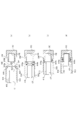
- FIG. 1 It is a perspective view which shows the outline of the whole of the cleaning tool 10 by 1st Embodiment. It is a perspective view which shows the outline of the whole cleaning tool 10 by 1st Embodiment and an optical connector OC. It is a side view which shows the left side surface of the cleaning tool 10 by 1st Embodiment. It is a side view which shows the right side surface of the cleaning tool 10 by 1st Embodiment. It is a perspective view which shows the state which removed the right housing 110R of the cleaning tool 10 by 1st Embodiment. It is a perspective view which shows the state which the left housing 110L of the cleaning tool 10 by 1st Embodiment was removed. FIG.
- FIG. 5 is a perspective view showing a state in which the supply reel 200 and the take-up reel 300 of the cleaning tool 10 according to the first embodiment are removed. It is a perspective view which shows the structure of the right housing 110R of the cleaning tool 10 by 1st Embodiment. It is a perspective view which shows the structure of the left housing 110L of the cleaning tool 10 by 1st Embodiment. It is a perspective view which shows the structure of the head part 400 (the head part 400 and the head holding body 420) of the cleaning tool 10 by 1st Embodiment. It is a perspective view which shows the path of the cleaning body CT in the head part 400 of the cleaning tool 10 by 1st Embodiment.
- the main body which is formed to be transportable and holds a sticky cleaning body, A head for bringing the cleaning body into contact with the optical connector, A control body that is relatively movable with respect to the main body and is in a first position that makes the head inaccessible to the optical connector, or in a state in which the head can contact the optical connector.
- the control body positioned at the second position to be A transmission state that transmits the operation of the control body to the cleaning body or a motion transmission body that does not transmit the operation of the control body is provided.
- control body In the movement from the first position to the second position, the control body causes the motion transmitter to be in a non-delivery state and does not convey the cleaning body.
- the control body is provided with an optical connector cleaning tool that conveys the cleaning body with the motion transmitting body in a transmitting state when moving from the second position to the first position.
- the optical connector cleaning tool includes a main body, a head, a control body, and an operation transmitter.
- the main body holds the cleaning body.
- the main body preferably houses and holds the cleaning body so that it can be moved.
- the main body holds the control body movably.
- the body preferably holds the motion transmitter operably.
- the cleaning body is formed so as to be transportable.
- the cleaning body is formed in a continuous body.
- the cleaning body has an elongated shape and can move along the longitudinal direction.
- the cleaning body has a tape-like shape.
- the cleaning body is sticky. Due to its adhesiveness, dust is transferred and removed.
- the cleaning body has a resin layer having adhesiveness. The adhesiveness can be controlled by the type of resin. The type of resin may be determined according to the dust.
- the head brings the cleaning body into contact with the optical connector. By bringing the cleaning body into contact with the optical connector, dust is transferred and removed.
- the shape and size of the head may be matched to the optical connector to be cleaned. Specifically, the shape and size of the head may be determined by the structure such as the shape and size of the ferrule of the optical connector.
- the control body can move relative to the main body.
- the movement may be a movement along a straight line or a movement along a curved line. It may be determined according to the form of the main body or the cleaning body such as reciprocating movement or rotational movement.
- the control body is positioned at least in the first position or the second position. It suffices that the controls can be positioned at a plurality of positions different from each other.
- the first position is a position where the head cannot contact the optical connector.
- the first position is a position where the head is separated from the optical connector.
- the second position is a position where the head can be brought into contact with the optical connector.
- the second position is a position where the head abuts on the optical connector.
- the motion transmitter has a transmission state or a non-delivery state.
- the transmission state is a state in which the operation of the control body is transmitted to the cleaning body. In the transmission state, the cleaning body is conveyed by the operation of the control body.
- the non-delivery state is a state in which the operation of the control body is not transmitted to the cleaning body. The cleaning body is not transported by the operation of the control body.
- control body moves from the first position to the second position, it does not transmit the movement operation and does not convey the cleaning body. That is, when the head is moved from a position where it cannot contact the optical connector to a position where it can contact the optical connector, the movement operation is not transmitted and the cleaning body is not conveyed. In other words, the cleaning body is not transported before the cleaning is started.
- control body when the control body moves from the second position to the first position, the control body transmits the movement operation and conveys the cleaning body. That is, when the head is moved from a position where it can contact the optical connector to a position where it cannot contact the optical connector, the movement operation is transmitted and the cleaning body is conveyed. In other words, after the cleaning is completed, the cleaning body is transported and the clean cleaning body is ready for use.
- the cleaning target is not limited to the ferrule of the optical connector as long as it can be cleaned with an adhesive cleaning body.
- the second embodiment is the first embodiment.
- the control body has a hollow structure capable of accommodating the head. When the control body is in the first position, the head is housed in the control body. When the control body is in the second position, the head is exposed from the control body.
- the head When the control body is in the first position, the head is housed in the control body. It is possible to prevent contamination of the cleaning body. Also, when the control body is located in the second position, the head can be exposed from the control body to clean the optical connector.
- the third embodiment is the third embodiment, in the first embodiment.
- the control body moves relative to the main body by pressing with the optical connector.
- the control body can be moved without touching the operator's hand, and the cleaning body can be less likely to be contaminated.
- the fourth embodiment is the second embodiment.
- the control body has an opening through which the head can pass.
- a shield that opens or closes the opening is provided.
- the fifth embodiment is the fourth embodiment. It has an urging means for generating an urging force that opens or closes the shield.
- the shield By opening or closing by the urging force, the shield can be controlled without the hands of the operator, so the cleaning body can be less likely to be contaminated.
- the sixth embodiment is the fourth embodiment. It has a connecting body that connects the motion transmitter to the shielding body and opens or closes the shielding body.
- the adhesive cleaning body is brought into contact with the ferrule end face OE of the optical connector OC, and dust or the like is transferred from the end face of the optical connector OC to the cleaning body.
- This is a cleaning tool for cleaning the optical connector OC.
- the cleaning body is a continuous body that extends continuously.
- the cleaning body has a long tape-like shape. After cleaning the ferrule end face OE of the optical connector OC, the contaminated cleaning body is moved to guide the clean part of the cleaning body to the head portion.
- the cleaning tool for the optical connector according to the first embodiment has a configuration in which the cleaning body is moved after cleaning and the clean cleaning body is guided to the head portion in advance. With this configuration, the next time cleaning is performed, the cleaning work can be performed immediately, and the work efficiency can be improved. Immediately after the cleaning body is moved, residual heat due to friction, residual energy, plastic deformation, and hysteresis loss (history loss) may occur in the cleaning body and surrounding members. By guiding the cleaning body to the head portion in advance, it is possible to provide a sufficient time to alleviate the effects, prevent these effects, and accurately remove the dust.
- a shielding member such as a shutter can be provided on the head portion so as to be openable and closable.
- the cleaning tool for the optical connector can be stored without contaminating the clean cleaning body.
- the shielding member makes it easy to handle the cleaning tool for the optical connector.
- the shielding member preferably opens and closes in conjunction with the operation of the operator's cleaning work. It is possible to prevent contamination of the cleaning body while maintaining the efficiency of the cleaning work. Further, the shielding member may be opened and closed by using a driving force such as an urging force of a spring.
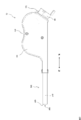
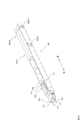
- FIG. 1 is a perspective view showing an overall outline of the cleaning tool 10 according to the first embodiment.
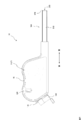
- FIG. 2 is a perspective view showing an overall outline of the cleaning tool 10 according to the first embodiment and an optical connector OC.
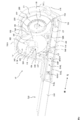
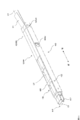
- FIG. 3 is a side view showing the left side surface of the cleaning tool 10 according to the first embodiment.
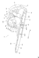
- FIG. 4 is a side view showing the right side surface of the cleaning tool 10 according to the first embodiment.
- FIG. 5 is a perspective view showing a state in which the right housing 110R of the cleaning tool 10 according to the first embodiment is removed.
- FIG. 6 is a perspective view showing a state in which the left housing 110L of the cleaning tool 10 according to the first embodiment is removed.
- FIG. 7 is a perspective view showing a state in which the supply reel 200 and the take-up reel 300 of the cleaning tool 10 are removed according to the first embodiment.
- FIG. 8 is a perspective view showing the configuration of the right housing 110R of the cleaning tool 10 according to the first embodiment.
- FIG. 9 is a perspective view showing the configuration of the left housing 110L of the cleaning tool 10 according to the first embodiment.
- FIG. 10 is a perspective view showing the configuration of the head portion 400 (head portion 400 and head holder 420) of the cleaning tool 10 according to the first embodiment.
- FIG. 11 is a perspective view showing a path of the cleaning body CT in the head portion 400 of the cleaning tool 10 according to the first embodiment.
- FIG. 12 is a cross-sectional view showing a path of the cleaning body CT in the head portion 400 of the cleaning tool 10 according to the first embodiment.
- the cap 160 is omitted for convenience.
- the cleaning tool 10 is a cleaning tool (cleaning tool) for the optical connector for cleaning the ferrule end face OE of the optical connector OC by using the cleaning body CT.
- the side or direction in which the cleaning head 410 of the cleaning tool 10 is located is the front side or the front direction
- the side or direction in which the housing 100 is located is the rear side or the rear direction.
- the front-rear direction may be referred to as the longitudinal direction of the head portion 400.
- the right side or direction from the rear side to the front side is referred to as the right side or the right direction
- the left side or the direction from the rear side to the front side is referred to as the left side.
- the side or direction in which the coil spring 140 is located is referred to as a lower side, a lower direction or a lower portion, and the side or direction in which the supply reel 200 or the take-up reel 300 is located is referred to as an upper side, an upper direction or an upper portion.
- the side that sends out and supplies the cleaning body CT is referred to as the upstream side, and the side on which the cleaning body CT is wound is referred to as the downstream side.
- the supply reel 200, which will be described later, is upstream, and the take-up reel 300 is downstream.
- the cleaning body CT is long and flexible, and has at least a resin layer, and the resin layer removes dirt such as dust by contacting the ferrule end face OE and the guide pin GP of the optical connector OC. can do.
- the cleaning body CT has, for example, an integrally continuous shape such as a tape-like shape or a thread-like shape.
- the width of the cleaning body CT is not particularly limited.
- the width of the cleaning body CT can be equal to or larger than the width of the ferrule end face OE of the optical connector OC. Further, the width of the cleaning body CT can be made larger than the width including the guide pin GP.
- the thickness of the cleaning body CT is not particularly limited, but can be, for example, 0.05 mm to 2 mm.
- the cleaning body CT may be a resin layer alone or may be laminated on a base material. Further, the release film may be laminated.
- the base material can be used as a support material when the resin layer alone cannot support the cleaning body CT.
- the release film can be used to protect the cleaning surface of the cleaning body CT from dirt and damage while the cleaning tool 10 of the present invention is not in use.
- the cleaning body CT is sent to the cleaning body head and brought into contact with the ferrule end face OE and the guide pin GP of the optical connector OC on the cleaning body head.
- the base material is laminated on the surface of the resin layer in contact with the cleaning body head.
- the release film is laminated on the surface of the resin layer opposite to the base material. The release film is peeled off and excluded from the cleaning body CT before the cleaning body CT reaches the cleaning body head.
- the resin layer is not particularly limited as long as dirt can be removed by contact with the ferrule end face OE of the optical connector OC and the guide pin GP, and for example, an adhesive, a resin foam (foam), and a guide pin GP are embedded. Examples thereof include resins, non-woven fabrics, and woven fabrics that have flexibility to pierce or penetrate.
- the material of the pressure-sensitive adhesive known materials can be used, and examples thereof include rubber-based pressure-sensitive adhesives, acrylic-based pressure-sensitive adhesives, silicone-based pressure-sensitive adhesives, urethane-based pressure-sensitive adhesives, and the like. Additives such as a tackifier and a filler may be blended in these pressure-sensitive adhesives.
- Known pressure-sensitive adhesives have the advantage that they are easily available and that the adhesive strength and the effect of preventing adhesive residue can be easily modified.
- the adhesive may be an adhesive as long as it has a function of adhering dirt to the cleaning body CT by contact, and for example, an olefin adhesive having weak adhesiveness can be used.
- the adhesive preferably has measures to suppress or prevent contamination of the ferrule end face OE of the optical connector OC, such as adhesive residue, when it comes into contact with the ferrule end face OE of the optical connector OC and the guide pin GP.
- the resin foam (foam) known ones can be used.
- the mechanism by which dirt can be captured on the cleaning surface formed by the resin foam (foam) needs to be verified for elucidation. For example, dirt pressed against the flexible cleaning surface is buried in the resin foam (foam) ( Alternatively, it is considered as an example that it becomes difficult to separate from the cleaning surface due to (semi-buried) and is trapped by the resin foam (foam).
- the resin foam (foam) does not adhere to the guide pin GP even if it penetrates the guide pin GP. This is because the resin foam (foam) has air bubbles, so it is a very flexible material, and the guide pin GP easily pierces and penetrates. Therefore, when the guide pin GP pierces and penetrates the resin foam (foam), the resin foam (foam) is entangled with the side surface portion of the guide pin GP and efficiently removes dust on the side surface portion of the guide pin GP. It is thought that it can be done. Even if it is not a resin foam, it can be preferably used as long as it does not cause foreign matter to adhere to the guide pin GP due to penetration.
- the material of the resin foam (foam) is not particularly limited, and known materials can be used.
- (Foam) can be mentioned. At least one or a combination of these materials can be used.
- urethane foam is preferable because it has excellent flexibility and low compression residual strain.
- it is also preferable to use (meth) acrylic foam because it has excellent strength, light weight, and heat insulation.
- the characteristics of the urethane foam and the characteristics of the acrylic foam can be adjusted according to the application, etc., depending on the mixing ratio. It is preferable because it can be adjusted.
- the structure of the bubbles contained in the resin foam (foam) is not particularly limited, and known ones can be used.
- the structure of the bubbles is a closed cell structure in which each bubble exists independently in the resin foam (foam), or an open cell structure in which each bubble is continuously connected in the resin foam (foam).
- the open cell structure includes a case where each bubble is connected by a communication through hole, and a case where the wall portion of the closed cell is broken and connected.
- the resin foam (foam) having an open cell structure is preferable because the guide pin GP can easily pierce or penetrate the resin foam (foam) and can efficiently remove dust.
- the method for producing the resin foam (foam) is not particularly limited, and the foam can be produced by a known method.
- the resin foam (foam) may be manufactured by either chemical foaming or physical foaming, or may be an open cell foam in which closed cells are formed and then the bubbles are physically crushed and communicated.
- the method for producing a foam disclosed in Japanese Patent Application Laid-Open No. 2012-56985 is suitable.
- the resin having the flexibility known ones can be used, and examples thereof include polyurethane resin and polyacrylic resin. Further, a gel material obtained by gelling them can be included. As the gel material, a flexible polyurethane resin or the like, which is generally called a polyurethane gel, can be used. The gel material is easily deformed, and at the same time, the guide pin GP can be easily embedded, pierced or penetrated. In this case, even if the adhesive strength of the gel material is weak, dirt can be removed from the ferrule end face OE and guide pin GP of the optical connector OC by embedding effect due to the softness of flexible polyurethane and by piercing or penetrating. Can be done.
- the gel material is slightly adhesive
- the optical connector OC can be easily attached and detached, no adhesive residue, etc., and the surface of the soft polyurethane to which dirt has adhered can be cleaned with a dust-free cloth moistened with water. , Can be reused.
- a soft composition disclosed in JP-A-2001-316448 can be preferably used.
- the material of the base material is not particularly limited, and known materials can be used.
- synthetic resins resins such as natural resins, rubbers such as natural rubbers and synthetic rubbers, natural fibers, synthetic fibers, fibers, and paper formed in a sheet shape can be used. Any of these materials can be used as long as the effects of the present invention are not impaired.
- extruded resin sheets narrow cutting of resin sheets, twisting of fibers, weaving of fibers (mesh material, woven fabric, etc.), laminated cloth, non-woven fabric, paper and the like can be used.
- a mesh material having a mesh structure with a mesh size of about 0.5 to 2.0 mm can be used.
- the cleaning body CT and the optical connector OC come into contact with each other, when the cleaning body CT is deformed so as to follow the shapes of the guide pin GP and the hole, the cleaning body CT needs to have flexibility.
- the base material an olefin-based or polyvinyl chloride-based synthetic resin is suitable.
- a base material having a structure that easily penetrates or a material that easily penetrates the cleaning body CT For example, a braided fiber, a laminated cloth, a non-woven fabric, or the like having a net-like structure can be preferably used.
- a part of the resin layer can be in a state of being invaded (impregnated) into the voids of the base material. .. In such a state, the adhesion between the base material and the resin layer becomes strong. Therefore, when the ferrule end face OE or guide pin GP of the optical connector OC is removed from the cleaning body CT, the resin layer is separated from the base material and adheres to the ferrule end face OE or guide pin GP of the optical connector OC. There is also an advantage that it is less likely to occur.
- Paper, non-woven fabric, woven fabric, or resin film can be preferably used as the base material of the material that can be easily penetrated.
- the resin that can be easily penetrated is not particularly limited, but is a resin that easily breaks after showing a certain elongation, such as a polyolefin resin such as polyethylene resin, or a uniaxially stretched or biaxially stretched polypropylene resin (PP).
- a resin that has been easily cut such as polyethylene terephthalate resin (PET) or the like, can be preferably used.
- the material of the release film can be a known material and is not particularly limited. It suffices that the surface of the sheet-like material such as a resin film or paper on the resin layer side is peeled.
- the peeling process is not particularly limited, and examples thereof include a method of applying a peeling agent such as dimethylsiloxane.
- the cleaning tool 10 mainly includes a housing 100, a supply reel 200, a take-up reel 300, a head portion 400, and a take-up control body 500.
- the housing 100, the supply reel 200, the take-up reel 300, the head portion 400, and the take-up control body 500 are formed of ABS resin (acrylonitrile, butadiene, styrene copolymer synthetic resin), POM (polyacetal) resin, or the like.
- the materials of the housing 100, the supply reel 200, the take-up reel 300, the head portion 400, and the take-up control body 500 are not limited to these, and may be any material having a certain shape and durability.
- the housing 100 rotatably holds the supply reel 200 and the take-up reel 300.
- the housing 100 has an elongated shape in the front-rear direction.
- the housing 100 stores the supply reel 200 and the take-up reel 300 side by side in the front-rear direction.
- the take-up reel 300 is located on the front side and the supply reel 200 is located on the rear side.
- the housing 100 has a recess 150 in the region between the supply reel 200 and the take-up reel 300.
- the operator's finger can be easily engaged with the recess 150, and the operation can be performed easily and accurately.
- the housing 100 has a right housing 110R and a left housing 110L.
- the housing that constitutes the right side portion of the housing 100 is the right housing, and the housing that constitutes the left side portion of the housing 100 is the left housing.
- the right housing 110R has a locking claw 154 and the left housing 110L has a locking hole 152.
- the outer shape of the right housing 110R and the outer shape of the left housing 110L are formed substantially line-symmetrically.
- the housing 100 can be integrally formed by facing the right housing 110R and the left housing 110L and locking the locking claw of the right housing 110R into the locking hole of the left housing 110L.
- the right housing 110R is a housing that constitutes the right side portion of the housing 100.
- ⁇ Guide groove 112R> At the lower part of the right housing 110R, two guide groove portions 112R are formed parallel to each other along the front-rear direction.
- the two guide groove portions 112R have an elongated shape.
- the stopper 114RF and the stopper 114RR are arranged below the right housing 110R.
- the stopper 114RF is arranged on the front side of the right housing 110R, and the stopper 114RR is arranged on the rear side of the stopper 114RF.
- the stopper 114RR defines the maximum front position MF of the take-up control body 500, and the stopper 114RF defines the maximum rear position MR of the take-up control body 500.
- the stopper 114RF and the stopper 114RR engage with the movement control hole 514R formed on the right side of the take-up control body 500.
- the stopper 114RR stops the take-up control body 500 at the maximum front position MF (state of FIG. 13A described later).
- the stopper 114RF stops the take-up control body 500 at the maximum rear position MR (state of FIG. 14A described later).
- the stopper 114RF engages with the front locking hole 424RF formed on the right side surface of the head holder 420.
- the stopper 114RR engages with the rear locking hole 424RR formed on the right side surface of the head holder 420.
- the head holder 420 is locked to the housing 100.
- the front projecting portion 116 and the rear projecting portion 118 are formed so as to project toward the right.
- the through hole 330 of the take-up reel 300 is inserted into the front protrusion 116.
- the front protrusion 116 rotatably holds the take-up reel 300.
- the through hole 230 of the supply reel 200 is inserted into the rear protrusion 118.
- the rear protruding portion 118 rotatably holds the supply reel 200.
- the remaining amount confirmation window 120 is a through hole for visually recognizing the amount (remaining amount) of the remaining cleaning body CT wound around the supply reel 200. The operator can check the remaining amount of the cleaning body CT and proceed with the operation.
- the spring holding portion 124R faces the spring holding portion 124L (described later) of the left housing 110L and holds the coil spring 140 so as to be expandable and contractible.
- the shape (coil shape) of the coil spring 140 can be maintained and the coil spring 140 can be stably held.
- the spring locking accommodating portion 128 accommodates the spring locking accommodating portion 126 formed in the left housing 110L, which will be described later. By covering the spring locking portion 126 with the spring locking accommodating portion 128, the fixed end portion 142 of the coil spring 140 can be held by the spring locking portion 126.
- ⁇ Left housing 110L >> ⁇ Guide groove 112L>
- two guide groove portions 112L are formed parallel to each other along the front-rear direction.
- the two guide groove portions 112L have an elongated shape.
- the stopper 114LF and the stopper 114LR are arranged at the lower part of the left housing 110L.
- the stopper 114LF is arranged on the front side of the left housing 110L, and the stopper 114LR is arranged on the rear side of the stopper 114LF.
- the stopper 114LR defines the maximum front position MF of the take-up control body 500, and the stopper 114LF defines the maximum rear position MR of the take-up control body 500.
- the stopper 114LF and the stopper 114LR engage with the movement control hole 514L formed on the left side of the take-up control body 500.
- the stopper 114LR stops the take-up control body 500 at the maximum front position MF (state of FIG. 13A described later).
- the take-up control body 500 is stopped at the stopper 114LF and the maximum rear position MR (state of FIG. 14A described later).
- the stopper 114LF engages with the front locking hole 424LF formed on the left side surface of the head holder 420.
- the stopper 114LR engages the rear locking hole 424LR formed on the left side surface of the head holder 420.
- the head holder 420 is locked to the housing 100.
- the pawl holding portion 122R is formed in a concave shape (recessed shape), and can accommodate and hold the fixed end portion 182 of the pawl 180 for the supply reel.
- a fixed end 182 of the supply reel pawl 180 is fixed to the pawl holding portion 122R.
- the pawl holding portion 122F is formed in a concave shape (recessed shape), and can accommodate and hold the fixed end portion 192 of the take-up reel pawl 190.
- the fixed end 192 of the take-up reel pawl 190 is fixed to the pawl holding portion 122F.
- the spring holding portion 124L faces the spring holding portion 124R and holds the coil spring 140 so as to be expandable and contractible.
- the spring locking portion 126 locks the fixed end portion 142 of the coil spring 140.
- the spring locking portion 126 can stably hold the coil spring 140 even when the coil spring 140 expands and contracts.
- the spring locking portion 126 is housed in the spring locking housing portion 128 formed in the right housing 110R described above.
- the fixed end 142 of the coil spring 140 can be prevented from coming off the spring locking portion 126.
- a cleaning body guide roller 130F is rotatably provided between the take-up reel 300 and the housing 100.
- the cleaning body guide roller 130F has a substantially cylindrical shape.
- the cleaning body guide roller 130F abuts on the cleaning body CT to bend the cleaning body CT and change the moving direction of the cleaning body CT. Specifically, the direction of the cleaning body CT returned from the cleaning head 410 can be changed to guide the user toward the take-up reel 300.
- the cleaning body CT can be stably wound on the take-up reel 300.
- a cleaning body guide roller 130R is rotatably provided between the supply reel 200 and the take-up reel 300.
- the cleaning body guide roller 130R has a substantially cylindrical shape.
- the cleaning body guide roller 130R abuts on the cleaning body CT to bend the cleaning body CT and change the moving direction of the cleaning body CT.
- the cleaning body CT sent out from the supply reel 200 can be changed in a certain direction and guided toward the cleaning head 410.
- By adjusting the cleaning body CT so as to face a certain direction it can be stably sent toward the cleaning head 410 without depending on the remaining amount of the cleaning body CT wound around the supply reel 200. ..
- the coil spring 140 is a spring formed in a coil shape, and is formed so as to be expandable and contractible. In each figure, for convenience, the coil spring 140 is shown in a columnar shape. The coil spring 140 generates an urging force according to the state of expansion and contraction.
- the coil spring 140 has two ends, a fixed end 142 and a moving end 144. The fixed end portion 142 is locked to the spring locking portion 126 of the left housing 110L. The moving end portion 144 is engaged with the coil spring pressing portion 540 of the take-up control body 500. When the take-up control body 500 moves to the rear side, the coil spring 140 contracts, and when the take-up control body 500 moves to the front side, the coil spring 140 expands. The coil spring 140 applies an urging force to the take-up control body 500.
- the feed reel pawl 180 has a leaf spring structure, and has a fixed end portion 182 and a leaf spring portion 184.
- the fixed end portion 182 is fixed to the pawl holding portion 122R of the left housing 110L.
- the leaf spring portion 184 has a long shape and can be elastically deformed by bending in a direction perpendicular to the longitudinal direction.
- the tip of the leaf spring portion 184 has an engaging end 186.
- the engaging end 186 has a bent shape.
- the engaging end 186 engages with the ratchet gear 222 of the pinion body 220 of the supply reel 200.
- the leaf spring portion 184 functions as a ratchet claw. The ratchet mechanism by the leaf spring portion 184 will be described later.
- the take-up reel pawl 190 has a leaf spring structure, and has a fixed end portion 192 and a leaf spring portion 194.
- the fixed end portion 192 is fixed to the pawl holding portion 122F of the left housing 110L.
- the leaf spring portion 194 has a long shape and can be elastically deformed by bending in a direction perpendicular to the longitudinal direction.
- the tip of the leaf spring portion 194 has an engaging end 196.
- the engaging end 196 has a bent shape.
- the engaging end 196 engages with the ratchet gear 322 of the pinion body 320 of the take-up reel 300.
- the leaf spring portion 194 functions as a ratchet claw. The ratchet mechanism by the leaf spring portion 194 will be described later.
- the cap 160 is a covering body for detachably covering the cleaning head 410. By covering the cleaning head 410 with the cap 160, it is possible to prevent contamination of the resin layer RL of the cleaning body CT.
- a cap holding portion 170 is formed at the rear portion of the housing 100. When cleaning with the cleaning tool 10, it is necessary to remove the cap 160 from the cleaning head 410. By attaching the removed cap 160 to the cap holding portion 170, the operator can clean the cap 160 without holding it by hand, and the cleaning work can be simplified.
- the supply reel 200 mainly has a left supply reel frame 210L and a right supply reel frame 210R. An unused cleaning body CT is wound between the left supply reel frame 210L and the right supply reel frame 210R so that it can be sent out (supplied).
- the left supply reel frame 210L has a substantially disk-like shape.
- the left supply reel frame 210L mainly has a pinion body 220, a fixing portion 224, and a through hole 230.
- the left supply reel frame 210L has a pinion body 220.
- the pinion body 220 is formed on the outside of the left supply reel frame 210L (the side facing the left housing 110L).
- the pinion body 220 has a substantially cylindrical shape with a low height.
- the pinion body 220 is formed coaxially with the left supply reel frame 210L.
- a ratchet gear (ratchet gear) 222 is formed along the outer peripheral surface of the pinion body 220.
- the ratchet gear 222 is composed of a row of teeth having a tooth surface asymmetric with respect to the radial direction of the supply reel 200.
- the teeth of the ratchet gear 222 have a tooth surface with a small pressure angle (a tooth surface with a steep inclination (large inclination)) (hereinafter referred to as a large inclined tooth surface) and a tooth surface with a large pressure angle (tilt) with the tip of the tooth sandwiched.
- Is composed of a loose (small inclination) tooth surface) hereeinafter referred to as an inclined small tooth surface).
- the inclined large tooth surface constitutes an engaging surface
- the inclined small tooth surface constitutes a slip surface and a sliding surface.
- a rotation direction for permitting rotation of the supply reel 200
- a rotation direction for prohibiting rotation.
- the ratchet gear 222 and the engaging end 186 of the supply reel pawl 180 described above constitute a ratchet mechanism (return prevention mechanism).
- the supply reel 200 allows rotation in the first rotation direction (for example, clockwise) (rotation permission direction), while the second rotation direction (for example, the direction opposite to the first rotation direction) is opposite to the first rotation direction. , Counterclockwise) rotation can be prohibited (rotation prohibition direction).
- the fixing portion 224 is formed so as to project from the central portion of the left supply reel frame 210L (see FIG. 5). In the supply reel 200, the fixing portion 224 is arranged toward the right supply reel frame 210R.
- the fixed portion 224 has a gap (not shown (similar to the gap 326 of the fixed portion 324 of the take-up reel 300 described later)), and the first end portion (not shown) on the longitudinal side of the cleaning body CT is provided.
- the cleaning body CT is fixed by sandwiching it in the gap.
- a flat portion 228 is formed at the tip of the fixed portion 224, and the right supply reel frame 210R can be held.
- a through hole 230 is formed in the center of the left supply reel frame 210L, and a rear protruding portion 118 of the right housing 110R is inserted into the through hole 230.
- the right supply reel frame 210R has a substantially disk-shaped shape.
- a circular through hole 232 is formed in the center of the right supply reel frame 210R, and a fixing portion 224 of the left supply reel frame 210L is inserted into the through hole 232.
- the cleaning body CT is wound in the gap between the left supply reel frame 210L and the right supply reel frame 210R.
- the unused clean cleaning body CT wound around the supply reel 200 can be gradually sent out and sent out toward the cleaning head 410.
- the adhesive resin layer is covered by the adjacent cleaning body CT.
- the cleaning body CT that has been overlapped adjacent to each other is separated to expose the adhesive resin layer.
- Winding reel 300 has a right take-up reel frame 310R. A used cleaning body CT is wound around the take-up reel 300.
- Right-hand reel frame 310R has a substantially disk-shaped shape.
- the right-hand reel frame 310R mainly has a pinion body 320, a fixing portion 324, and a through hole 330.
- the right take-up reel frame 310R has a pinion body 320.
- the pinion body 320 is formed on the outside of the right take-up reel frame 310R (the side facing the right housing 110R).
- the pinion body 320 has a substantially cylindrical shape with a low height.
- the pinion body 320 is formed coaxially with the right take-up reel frame 310R.
- a ratchet gear (ratchet gear) 322 is formed along the outer peripheral surface of the pinion body 320.
- the ratchet gear 322 is composed of a row of teeth having a tooth surface asymmetric with respect to the radial direction of the take-up reel 300.
- the teeth of the ratchet gear 322 are composed of a tooth surface having a small pressure angle (a tooth surface having a steep inclination) and a tooth surface having a large pressure angle (a tooth surface having a gentle inclination) across the tooth tip.
- a rotation direction rotation permission direction
- a rotation prohibition direction for prohibiting rotation.
- the ratchet mechanism (motion transmission ratchet mechanism) is configured by the ratchet gear 322 and the rack 536 of the take-up control body 500 described later. Further, the ratchet gear 322 and the engaging end 196 of the take-up reel pawl 190 described above constitute a ratchet mechanism (rotation direction defined ratchet mechanism).
- the fixing portion 324 is formed so as to project from the central portion of the right take-up reel frame 310R. In the take-up reel 300, the fixing portion 324 is arranged toward the left housing 110L. The fixing portion 324 has a gap 326, and the cleaning body CT is fixed by sandwiching the second end portion (not shown) on the longitudinal side of the cleaning body CT in the gap 326. A through hole 330 is formed in the central portion of the right take-up reel frame 310R, and a front protruding portion 116 of the right housing 110R is inserted into the through hole 330.
- a left take-up reel frame may be provided. By providing the left take-up reel frame, the cleaning body CT after taking up can be accurately held.
- the head portion 400 is arranged so as to project forward from the housing 100.
- the head portion 400 has a cleaning head 410 and a head holder 420.
- the cleaning head 410 has a contact portion 412 for bringing the cleaning body CT into contact with the ferrule end face OE of the optical connector OC.
- the contact portion 412 has a size and a shape corresponding to the ferrule end face OE of the optical connector OC.
- the contact portion 412 is formed with two accommodating holes 414 for accommodating the two guide pins GP protruding from the ferrule end surface OE of the optical connector OC.
- the resin layer RL of the cleaning body CT can reach the root of the guide pin GP of the ferrule end face OE of the optical connector OC, and dust near the root of the guide pin GP can be accurately removed. can do.
- the removal of dust adhering to the vicinity of the root of the guide pin GP will be described in detail later (see FIGS. 16 and 17 described later).
- the cleaning head 410 has a long, thin, flat rectangular parallelepiped shape.
- the cleaning head 410 is held at a fixed position on the front end 426 of the head holder 420, which will be described later.
- the cleaning body CT sent out from the supply reel is guided by the contact portion 412 and positioned at the contact portion 412.
- the cleaning head 410 can be detachably provided on the head holder 420. Depending on the ferrule end face OE of the optical connector OC, it can be replaced with the corresponding cleaning head 410 as appropriate.
- the resin layer RL of the cleaning body CT positioned at the contact portion 412 is made to face the ferrule end face OE of the optical connector OC, and the resin layer RL is brought into contact with the ferrule end face OE of the optical connector OC. Dust present on the ferrule end face OE of the optical connector OC is transferred to the resin layer RL. By this transfer, dust on the ferrule end face OE of the optical connector OC can be removed. After that, the cleaning body CT is wound from the contact portion 412 toward the take-up reel 300. The displacement of the cleaning body CT will be described in detail later.
- the head holder 420 has a long and constant shape. Specifically, the head holder 420 has a long square tubular shape and a hollow structure.
- the head holder 420 movably accommodates the cleaning body CT from the supply reel 200 to the take-up reel 300. Specifically, the head holding body 420 is sent out from the supply reel 200, and can move the cleaning body CT until it is wound on the winding reel 300 via the contact portion 412 of the cleaning head 410 described above. Contain.
- a holding hole 422 is formed on the front side surface of the head holding body 420.
- a pin 416 (see FIG. 10) formed in the cleaning head 410 is inserted into the holding hole 422. In this way, the cleaning head 410 can be held at a fixed position on the head holder 420.
- Two locking holes 424RF and 424RR are formed on the right side surface of the rear part of the head holder 420.
- the locking hole 424RF is formed on the front side, and the locking hole 424RR is formed on the rear side.
- the front locking hole 424RF engages the stopper 114RF of the right housing 110R, and the rear locking hole 424RF engages the stopper 114RR of the right housing 110R.
- two locking holes 424LF and 424LR are formed on the left side surface of the rear part of the head holder 420.
- the locking hole 424LF is formed on the front side
- the locking hole 424LR is formed on the rear side.
- the front locking hole 424LF engages the stopper 114LF of the left housing 110L
- the rear locking hole 424LR engages the stopper 114LR of the left housing 110L.
- the head portion 400 By locking the head portion 400 to the housing 100 by the locking holes 424RF and 424RR and the locking holes 424LF and 424LR, the head portion 400 can be held at a fixed position on the housing 100.
- Position of cleaning head 410 The cleaning head 410 is held at a fixed position of the head holder 420 which has a fixed shape and is locked at a fixed position with respect to the housing 100. Therefore, the cleaning head 410 is always located at a fixed position with respect to the housing 100. That is, the cleaning head 410 does not move with respect to the housing 100 before, during, and after the cleaning work, and is always in a fixed position with respect to the housing 100 and the head holder 420. Be retained.
- the cleaning body CT supplied to the contact portion 412 of the cleaning head 410 can be transferred to the ferrule end face of the optical connector OC. It can be pressed against the OE with a constant force, and dust on the ferrule end face OE can be stably removed without depending on the skill of the operator.
- the front end of the cleaning head 410 protrudes from the head holding body 420, and the contact portion 412 of the cleaning head 410 is arranged at a position protruding from the head holding body 420.
- the cleaning body CT can be directed to the outside, and the cleaning body CT supplied to the contact portion 412 can be accurately contacted with the ferrule end surface OE of the optical connector OC.
- the resin layer RL of the cleaning body CT can be prevented from being contaminated, and a clean state can be maintained.
- the movable control body 510 which will be described later, is arranged outside the head holding body 420, and the head holding body 420 functions as a partition wall.
- the head holding body 420 can block the dust and make it difficult for the dust to enter the inside of the head holding body 420, thereby contaminating the resin layer RL. Can be prevented.
- the coil spring 140 for driving the control body 510 is arranged at the rear part of the housing 100, that is, at a position separated from the head holder 420, and dust is generated by the expansion and contraction of the coil spring 140. Even in this case, contamination of the resin layer RL can be prevented.
- the coil spring 140 arranged at the rear of the housing 100 is housed inside the spring holding portions 124L and 124R, and the spring holding portions 124L and 124R function as partition walls, and dust spreads due to expansion and contraction of the coil spring 140. Can be prevented.
- the take-up control body 500 has a control main body 510, a control end face 520, a take-up extension portion 530, and a coil spring pressing portion 540.
- Control body 510 has a long substantially square tubular shape and penetrates in the longitudinal direction. That is, the control main body 510 has a hollow structure, and the above-mentioned head portion 400 (head holder 420 and cleaning head 410) is housed inside the control main body 510.
- the control main body 510 can move along the longitudinal direction of the head portion 400 with respect to the head portion 400 housed inside.
- the control main body 510 can move the outside of the head portion 400 along the longitudinal direction of the head portion 400, and the movement of the control main body 510 causes the entire winding control body 500 to move with respect to the head portion 400 and the housing 100. Can move along the longitudinal direction of the head portion 400.
- the operation and operation of the take-up control body 500 will be described later.
- Two guide ridges 512R are formed on the right side surface of the control body 510.
- the two guiding ridges 512R have an elongated ridge-shaped shape.
- the two guide ridges 512R are formed at two locations, the upper part and the lower part of the right side surface of the control body 510, parallel to each other along the longitudinal direction of the control body 510.
- Two guide ridges 512L are formed on the left side surface of the control body 510.
- the two guiding ridges 512L have an elongated ridge-shaped shape.
- the two guide ridges 512R are formed at two locations, the upper part and the lower part of the left side surface of the control body 510, parallel to each other along the longitudinal direction of the control body 510.
- a long movement control hole 514R is formed on the right side surface of the control main body 510.
- the movement control hole 514R has a substantially oval through hole shape.
- the movement control hole 514R is formed between two long guide ridges 512R along the longitudinal direction of the control body 510.
- a long movement control hole 514L is formed on the left side surface of the control body 510.
- the movement control hole 514L has a substantially oval through hole shape.
- the movement control hole 514L is formed between two long guide ridges 512L along the longitudinal direction of the control body 510.
- the movement control hole 514R and the movement control hole 514L are formed so that the right side surface and the left side surface of the control main body 510 face each other.
- Control end face 520 is an end face formed at the front end portion of the control main body 510.
- the control end surface 520 is an end surface for facing and abutting the optical connector widening surface OW of the optical connector OC.
- the control end surface 520 is formed so as to be in contact with the optical connector widening surface OW so as to be engaged with the control end surface 520.
- the cleaning tool 10 is positioned so as to face the optical connector widening surface OW of the optical connector OC, and the control end surface 520 is brought close to the optical connector widening surface OW of the optical connector OC until it abuts (engages) with the optical connector widening surface OW.
- the control body 510 when the operator applies force to the cleaning tool 10 while maintaining the state in which the control end surface 520 of the control body 510 is in contact (engagement) with the optical connector widening surface OW of the optical connector OC, the control body 510 is used. Moves relative to the rear of the housing 100. By moving the control main body 510 to the rear, the contact portion 412 of the cleaning head 410 is exposed from the control main body 510 and approaches the ferrule end surface OE of the optical connector OC.
- the control body 510 When the operator further applies force to the cleaning tool 10, the control body 510 further moves relatively to the rear of the housing 100. By moving the control body 510, the contact portion 412 of the cleaning head 410 comes closer to the ferrule end face OE of the optical connector OC, and the cleaning body CT of the contact portion 412 comes into contact with the ferrule end face OE. As a result, the clean resin layer RL of the cleaning body CT comes into contact with the ferrule end face OE.
- control main body 510 moves relative to the housing 100 and the head portion 400, but the control end surface 520 of the control main body 510 widens the optical connector of the optical connector OC. It is in a state of being in contact (engaged) with the surface OW, and the take-up control body 500 and the control body 510 are stationary with respect to the optical connector OC.
- the housing 100 and the head portion 400 move toward the optical connector OC.
- the take-up extension portion 530 extends from the control main body 510 toward the take-up reel 300.
- the winding extension portion 530 has a curved portion 532 and a rack forming portion 534.
- the curved portion 532 has a shape curved by approximately 90 degrees.
- the curved portion 532 projects substantially perpendicular to the longitudinal direction of the head portion 400, is curved approximately 90 degrees, is substantially parallel to the longitudinal direction of the head portion 400, and extends toward the take-up reel 300.
- the curved portion 532 is made of a material that can be elastically deformed, and can be elastically deformed as appropriate.
- the rack forming portion 534 is connected to the curved portion 532 and has a substantially linear elongated shape.
- a rack (a row of teeth in which the tooth tips are arranged in a plane) 536 is formed along the longitudinal direction of the head portion 400.
- the rack 536 engages with the ratchet gear 322 of the take-up reel 300.
- the rack forming portion 534 can also move in the front-rear direction.
- the take-up reel 300 is rotated when the rack forming portion 534 moves in the front direction. The operation of the control main body 510 and the take-up reel 300 will be described in detail later.
- a coil spring pressing portion 540 is formed at the rear end of the take-up control body 500.
- the moving end portion 144 of the coil spring 140 is engaged with the coil spring pressing portion 540.
- the side portion of the coil spring 140 is supported by the spring holding portion 124L and the spring holding portion 124R, and the coil spring 140 is stretchably held between the coil spring pressing portion 540 and the spring locking portion 126 of the left housing 110L.
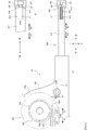
- FIG. 13A is a cross-sectional view showing a state in which the operator is grasping the cleaning tool 10 and approaching it toward the optical connector OC.
- the control end surface 520 is brought close by the operator until it comes into contact (engagement) with the optical connector widening surface OW of the optical connector OC.
- Position of take-up control body 500 As shown in FIG. 13A, the cleaning tool 10 is in a state of being separated from the optical connector OC. Specifically, the control end surface 520 of the take-up control body 500 is separated from the optical connector widening surface OW of the optical connector OC.
- ⁇ Maximum front position MF of control body 510> In this state, only the urging force of the coil spring 140 is applied to the control body 510. The urging force of the coil spring 140 urges the control body 510 forward with respect to the housing 100 (and the head portion 400). By urging, the movement control hole 514R engages with the stopper 114RR, the movement control hole 514L engages with the stopper 114LR, the control body 510 is locked by the stopper 114RR and the stopper 114LR, and the control body 510 is on the frontmost side. Located (maximum front position MF). The maximum front position MF is the home position of the control body 510.
- Position of the contact portion 412 of the cleaning head 410 When the control main body 510 is located at the maximum front position MF, the contact portion 412 of the cleaning head 410 does not protrude from the control end surface 520 of the take-up control body 500, and is housed in the control main body 510. Therefore, the cleaning body CT guided to the contact portion 412 of the cleaning head 410 is separated from the ferrule end surface OE.
- FIG. 13B is a cross-sectional view showing a state in which the operator presses the cleaning tool 10 against the optical connector OC and the contact portion 412 of the cleaning head 410 is approaching the ferrule end surface OE.
- the operator brings the control end surface 520 close to the optical connector widening surface OW of the optical connector OC until it abuts (engages).
- the operator applies force to the cleaning tool 10 while maintaining the state in which the control end surface 520 of the control main body 510 is in contact (engagement) with the optical connector widening surface OW of the optical connector OC.
- the control main body 510 is pressed by the optical connector widening surface OW and moves relatively to the rear of the housing 100, and the contact portion 412 of the cleaning head 410 approaches the ferrule end surface OE of the optical connector OC.
- ⁇ Position of take-up control body 500 As shown in FIG. 13B, the control end surface 520 of the take-up control body 500 is pressed against the optical connector widening surface OW of the optical connector OC by the operation of the operator. By pressing the control end surface 520 of the take-up control body 500, a drag force is generated on the optical connector widening surface OW of the optical connector OC. By pressing the control end surface 520, the control end surface 520 is in a state of being in contact (engagement) with the optical connector widening surface OW.
- the urging force of the coil spring 140 and the drag force from the optical connector widening surface OW are applied to the control main body 510.
- the drag force from the optical connector widening surface OW is larger than the urging force of the coil spring 140
- the drag force from the optical connector widening surface OW causes the control body 510 to be relatively relative to the housing 100 (and the head portion 400). Move backward (see arrow A1). In other words, the control body 510 moves in the direction of being housed in the housing 100.
- FIG. 14A is a cross-sectional view showing a state in which the operator further presses the cleaning tool 10 against the optical connector OC to bring the contact portion 412 of the cleaning head 410 into contact with the ferrule end surface OE.
- ⁇ Maximum rear position MR of take-up control body 500> As shown in FIG. 14A, the movement control hole 514R is engaged with the stopper 114RF, the movement control hole 514L is engaged with the stopper 114LF, and the control main body 510 is locked by the stopper 114RF and the stopper 114LF to control.
- the main body 510 is located on the rearmost side (maximum rear position MR). In this way, the control body 510 can be stopped at the maximum rear position MR.
- FIG. 14B is a cross-sectional view showing a state in which the operator relaxes the force of pressing the cleaning tool 10 against the optical connector OC and the contact portion 412 of the cleaning head 410 is separated from the ferrule end face OE.
- the cleaning body CT When the cleaning body CT is pulled by the take-up reel 300 (arrow A3 in FIG. 14B), the cleaning body CT is sent out from the supply reel 200 (arrow A4 in FIG. 14B), and the cleaning body CT is sent out.
- the clean resin layer RL is supplied to the contact portion 412 of the cleaning head 410 (arrow A5 in FIG. 14B).
- the take-up control body 500 moves between the maximum front position MF and the maximum rear position MR. Therefore, the take-up control body 500 can always be moved by a certain length (see FL in FIG. 13A), the feed length of the cleaning body CT can also be made constant, and the skill of the operator. A clean resin layer RL can always be supplied to the contact portion 412 of the cleaning head 410 regardless of the skill level.
- the supply reel 200 is held in the housing 100, and the cleaning body CT sent out from the supply reel 200 is housed in the housing 100 and the head holding body 420 until it reaches the cleaning head 410, and the resin layer RL of the cleaning body CT. Can be kept clean.
- the cleaning body CT When the cleaning body CT is sent out from the supply reel 200, the winding is unwound and the resin layer RL of the cleaning body CT is exposed. After being sent out from the supply reel 200, the resin layer RL of the cleaning body CT preferably goes straight and reaches the cleaning head 410 without contacting any member. On the surface opposite to the resin layer RL, the path of the cleaning body CT can be appropriately changed by a roller, a guide, or the like. Further, even when the resin layer RL of the cleaning body CT comes into contact with the member, the resin layer RL of the cleaning body CT can be kept clean by using the clean member.
- the operator weakens the force on the cleaning tool 10, and the urging force of the coil spring 140 causes the control body 510 to move relatively forward and return to the maximum front position MF, which is the home position.
- the cleaning body CT is pulled. That is, the control body 510 continues to move and the cleaning body CT is towed until the control body 510 reaches the home position.
- the cleaning body CT after cleaning which was located at the contact portion 412, moves to a position separated from the contact portion 412 until the cleaning is completed and the control main body 510 returns to the home position.
- the clean resin layer RL of the cleaning body CT is newly supplied to the contact portion 412 and positioned. That is, after the cleaning is completed, the clean resin layer RL of the cleaning body CT is constantly newly supplied to the contact portion 412 by moving the control main body 510.
- the control body 510 moves forward for cleaning, the winding reel 300 is prohibited from rotating by the rotation direction defining ratchet mechanism described later, so that the cleaning body CT does not move and the cleaning head 410 comes into contact with the cleaning body CT.
- the resin layer RL of the cleaning body CT supplied to the portion 412 is maintained at the position of the contact portion 412. Therefore, after cleaning, the clean resin layer RL newly supplied to the contact portion 412 is brought into contact with the ferrule end face OE without moving the contact portion 412 as it is, and the ferrule end face OE is immediately cleaned. can do.
- control body 510 and take-up reel 300 >>>>>>>>>>>>>>>>>>>>>> As described above, the control main body 510 can move rearward or forward relative to the housing 100 by the balance between the urging force of the coil spring 140 and the drag force from the optical connector widening surface OW.
- the take-up reel 300 can be driven by the operation of the control body 510.
- the operation of the control main body 510 and the operation of the take-up reel 300 will be described with reference to FIG.
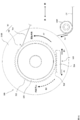
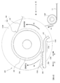
- FIG. 15 is a schematic view showing a state of engagement between the rack 536 and the ratchet gear 322 and engagement between the engagement end 196 and the ratchet gear 322.
- the rack 536 is covered with the take-up extension portion 530 (see FIGS. 13 and 14 and the like), in FIG. 15, the rack 536 is specified for the sake of explanation.
- the control main body 510 has a take-up extension portion 530, and a rack 536 is formed in the take-up extension portion 530.
- the rack 536 engages with the ratchet gear 322 of the take-up reel 300.
- the take-up reel pawl 190 has a leaf spring portion 194, and the leaf spring portion 194 is formed with an engaging end 196.
- the engaging end 196 also engages with the ratchet gear 322 of the take-up reel 300. That is, the ratchet gear 322 of the take-up reel 300 engages with the rack 536 of the control body 510 and also with the engaging end 196 of the take-up reel pawl 190.
- the operation of the take-up reel 300 is controlled by these two engagements.
- the ratchet gear 322 of the take-up reel 300 and the rack 536 of the take-up extension portion 530 constitute an operation transmission ratchet mechanism.
- the motion transmission ratchet mechanism can define a state in which motion transmission is possible and a state in which motion transmission is difficult from the control main body 510 to the take-up reel 300.
- a rack and pinion mechanism is also configured from the engagement between the rack 536 of the take-up extension portion 530 and the ratchet gear 322 of the take-up reel 300.
- the rack and pinion mechanism converts the linear motion of the control body 510 into the rotary motion of the take-up reel 300, and the motion transmission ratchet mechanism transmits the motion from the control body 510 to the take-up reel 300.
- ⁇ Engagement between ratchet gear 322 and engaging end 196 >> ⁇ Rotation direction regulation ratchet mechanism>
- the ratchet gear 322 of the take-up reel 300 and the engaging end 196 of the take-up reel pawl 190 constitute a rotation direction defining ratchet mechanism.
- the rotation direction defining ratchet mechanism can define the rotation permitted state and the rotation prohibited state of the take-up reel 300.
- control body 510 moves rearward relative to the housing 100 (and the head portion 400) (see arrows A1 in FIGS. 13B, 14A and 15). In other words, the control body 510 moves in the direction of being housed in the housing 100.
- the winding extension portion 530 is formed so as to be elastically deformable.
- the take-up extension portion 530 can swing in a direction away from the take-up reel 300 or in a direction approaching the take-up reel 300 due to elastic deformation. Therefore, even when the take-up reel 300 does not rotate, the rack 536 of the take-up extension portion 530 slides on the ratchet gear 322 due to the elastic deformation of the take-up extension portion 530, so that the control main body 510 Can move backwards.
- control body 510 moves forward relative to the housing 100 (and the head portion 400) (see arrows B1 in FIGS. 14B and 15). In other words, the control body 510 moves in the direction of being discharged to the housing 100.
- the leaf spring portion 194 is formed so as to be elastically deformable.
- the leaf spring portion 194 can swing in a direction away from the take-up reel 300 or in a direction approaching the take-up reel 300 due to elastic deformation. Therefore, when the take-up reel 300 rotates, the take-up reel 300 rotates because the engaging end 196 of the leaf spring portion 194 slides on the ratchet gear 322 due to the elastic deformation of the leaf spring portion 194. can do.
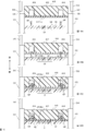
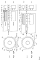
- 16 (a) to 16 (d) are cross-sectional views showing a process of cleaning the ferrule end surface OE of the optical connector OC using the cleaning tool 10. For example, it can be used for cleaning MPO connectors and the like.
- 16 (a) to 16 (d) show the relative positional relationship between the ferrule FE and the cleaning body CT in the cleaning process.
- the ferrule FE is provided with the ends of 12 optical fiber OFs arranged side by side. Further, the ferrule FE is provided with two guide pins GP projecting vertically from the ferrule end face OE (in a direction away from the ferrule end face OE) with twelve optical fiber OFs interposed therebetween.
- the operator grasps the cleaning tool 10, and as shown in FIG. 2, brings the cleaning head 410 of the cleaning tool 10 close to the opening OP of the optical connector OC so as to face it.
- the housing end face OS of the optical connector OC is engaged with the control end face 520 of the control main body 510, and a force is applied to the cleaning tool 10.
- the cleaning head 410 can be inserted into the opening OP of the optical connector OC while the control body 510 is housed in the housing 100, and the contact portion 412 of the head portion 400 can be inserted into the ferrule of the optical connector OC. It can be brought closer to the ferrule end face OE of FE.
- the resin layer RL of the cleaning body CT can be brought into close contact with the ferrule end face OE. The specific process will be described below.
- the resin layer RL of the cleaning body CT faces the ferrule end face OE at a position separated from each other.
- the control end surface 520 of the control body 510 engages with the housing end surface OS of the optical connector OC.
- the resin layer RL of the cleaning body CT of the contact portion 412 of the head portion 400 approaches the ferrule end surface OE of the optical connector OC.
- the resin layer RL of the cleaning body CT comes into contact with the tips of the two guide pins GP of the ferrule FE and is pressed by the two guide pins GP to elastically deform.
- the resin layer RL of the cleaning body CT further approaches the ferrule end face OE of the optical connector OC.
- the resin layer RL is pressed by the two guide pins GP and begins to cover the two guide pins GP by the urging force (restoring force) generated in the resin layer RL.
- the resin layer RL reaches the ferrule end face OE as shown in FIG. 16D.
- the portion elastically deformed by the contact of the two guide pins GP is covered with the resin layer RL up to the roots of the two guide pins GP by the urging force (restoring force) generated in the resin layer RL.
- the resin layer RL can be brought into close contact with the entire ferrule end face OE without creating a gap between the resin layer RL and the ferrule end face OE.
- the entire dust on the ferrule end face OE can be transferred by the adhesive force of the resin layer RL. It is attached with. Dust around the roots of the two guide pin GPs and dust adhering to the two guide pin GPs can also be transferred and removed by the adhesive force of the resin layer RL.
- the entire two guide pins GP can be covered with the resin layer RL by using the urging force (restoring force) of the resin layer RL.
- the cleaning head 410 is formed with accommodating holes 414 for accommodating the two guide pin GPs, and even when the resin layer RL reaches the ferrule end face OE, the resin layer RL is accommodated together with the entire guide pin GP. It is housed in hole 414. By providing the accommodating hole 414, dust can be accurately removed even in the ferrule FE on which the guide pin GP is formed. Further, since the resin layer RL can also be accommodated in the accommodating hole 414, the deformation of the resin layer RL due to the urging force (restoring force) is not hindered, and the entire guide pin GP can be covered with the resin layer RL.
- the resin layer RL is elastically deformed according to the shape and size of the two guide pin GPs without being pierced by the two guide pins GP.
- An example is shown in which the resin layer RL is covered up to the roots of the two guide pin GPs by the urging force (restoring force) generated in the resin layer RL, but the two guide pin GPs are pierced into the resin layer RL.
- the resin layer RL may be plastically deformed.
- 17 (a) to 17 (d) are diagrams showing an example of a case where the resin layer RL is plastically deformed. Whether the resin layer RL is elastically deformed or plastically deformed may be determined by appropriately determining the shore A hardness of the resin layer RL.
- FIG. 17 (a) is in the same state as FIG. 16 (a).
- the resin layer RL is punctured by the two guide pins GP and is plastic. It deforms and puncture starts from the beginning of contact with the two guide pins GP.
- FIG. 17C plastic deformation further progresses, and the two guide pins GP are gradually stabbed into the resin layer RL.
- FIG. 17D the cleaning body CT reaches the ferrule end face OE while the resin layer RL is plastically deformed.
- the resin layer RL of the cleaning body CT can be adhered to the roots of the two guide pins GP. Also in this case, dust adhering to the periphery of the roots of the two guide pins GP and the two guide pins GP can also be transferred and removed by the adhesive force of the resin layer RL.
- FIG. 18 is a cross-sectional view showing the configuration of the shielding member 600.
- the shielding member 600 has two shielding plates 610a and 610b and a torsion spring (torsion spring) 620.
- the two shielding plates 610a and 610b are rotatably provided on the wall portion of the control main body 510.
- the two shielding plates 610a and 610b can be rotated approximately 90 degrees.
- the two shielding plates 610a and 610b open and close in a double-door manner.
- the shielding plates 610a and 610b are urged by the torsion spring 620.
- the shielding plates 610a and 610b close the opening 550 by the urging force of the torsion spring 620 (FIG. 18A).
- the shielding plates 610a and 610b come into contact with the housing end face OS of the optical connector OC (FIG. 18 (b)). Further, when the operator brings the cleaning tool 10 closer to the optical connector OC, the shielding plates 610a and 610b can be pressed and opened by the housing end face OS (FIGS. 18 (c) and 18 (d)).
- the shielding plates 610a and 610b are closed by the urging force of the torsion spring 620.
- the shielding member 700 has two shielding plates 710a and 710b and support rods 720a and 720b.
- the two shielding plates 710a and 710b are rotatably provided on the wall portion of the control main body 510.
- the two shielding plates 710a and 710b can be rotated approximately 90 degrees.
- the two shielding plates 710a and 710b open and close in a double-door manner.
- the shielding plate 710a is connected to the support rod 720a, and the shielding plate 710b is connected to the support rod 720b.
- the support rods 720a and 720b are engaged with the ratchet gear 322 of the pinion body 320 of the take-up reel 300 and the ratchet gear 222 of the pinion body 220 of the supply reel 200. By rotating the take-up reel 300 and the supply reel 200, the support rods 720a and 720b can move along the control main body 510.
- the shielding plates 710a and 710b are opened and closed by the movement of the support rods 720a and 720b.
- a shielding member that opens and closes in a double-door manner is shown, but a shielding member that opens and closes in a sliding manner may be used. Further, the shielding member may be formed by a member having deformable flexibility. By closing the opening 550, it is sufficient to prevent dust from entering from the outside and prevent contamination.
- a first position for example, maximum front position MF
- a control body positioned at a second position for example, the maximum rear position MR, etc.
- the control body In the movement from the first position to the second position, the control body causes the motion transmitter to be in a non-delivery state and does not convey the cleaning body.
- the control body disagrees with the motion transmitter in moving from the second position to a third position (eg, boundary 1542, etc.) between the first position and the second position.
- An optical connector cleaning tool is provided which brings the motion transmitter into the transmission state and conveys the cleaning body in the movement from the third position to the first position in the reaching state.
- FIG. 20 is a schematic view showing a winding extension portion 1530 of the cleaning tool 20 and a pinion body 320 of the winding reel 300 according to the second embodiment.
- FIG. 21 is a schematic view showing an outline of the cleaning tool 20 according to the second embodiment.
- 21 (a) is a schematic view showing the configurations of the cleaning tool 20 and the optical connector OC in a side view, similarly to FIGS. 13 and 14.
- FIG. 21B is a schematic view showing a part of the cleaning head 410 of the cleaning tool 20 and the optical connector OC in a plan view.
- 21 (a) and 21 (b) are shown by breaking the periphery of the cleaning head 410 for clarity.
- the same reference numerals are given to the same configurations as those of the first embodiment.
- the take-up extension portion 1530 is provided so as to extend from the control main body 510 toward the take-up reel 300, similarly to the take-up extension portion 530.
- the take-up extension portion 1530 is connected to the control main body 510.
- the take-up extension portion 1530 has the same shape as the take-up extension portion 530. In FIG. 20, for convenience, only a part of the winding extension portion 1530 is shown. In the second embodiment, the configuration of the winding extension portion 1530 is different from that of the winding extension portion 530 of the first embodiment, and other members have the same configuration.
- the winding extension portion 1530 has a curved portion 532 and a straight portion 1540.
- the curved portion 532 has a structure similar to that of the first embodiment.
- the straight portion 1540 has a linear shape and a long shape.
- the straight portion 1540 has a non-rack forming portion 1538 and a rack forming portion 534.
- the non-rack forming portion 1538 and the rack forming portion 534 are connected in series to form a straight portion 1540.
- the non-rack forming portion 1538 and the rack forming portion 534 are adjacent to each other and extend linearly as a whole.
- the rack forming portion 534 has an elongated shape that is substantially linear.
- a plurality of racks (rows of teeth having tooth tips arranged in a plane) 536 are formed along the longitudinal direction of the head portion 400.
- the rack 536 engages with the ratchet gear 322 of the take-up reel 300.
- the take-up reel 300 rotates and the cleaning body CT is displaced.
- Non-rack forming part 1538 The non-rack forming portion 1538 is connected to the curved portion 532. No rack is formed in the non-rack forming portion 1538.
- the non-rack forming portion 1538 does not engage the ratchet gear 322 even when it moves the position closest to the ratchet gear 322. Therefore, even when the non-rack forming portion 1538 moves in the position closest to the ratchet gear 322 in the arrow A1 direction or the B1 direction shown in FIG. 20, the take-up reel 300 does not rotate.
- the cleaning body CT does not displace.
- the straight portion 1540 has a boundary portion 1542 at the boundary between the rack forming portion 534 and the non-rack forming portion 1538. With the boundary portion 1542 as a boundary, the engagement or disengagement of the rack 536 and the ratchet gear 322 is switched, the rotation or non-rotation of the take-up reel 300 is switched, and the displacement or non-displacement (stop) of the cleaning body CT is switched. ..
- the cleaning tool 20 according to the second embodiment has the same configuration as the cleaning tool 10 according to the first embodiment, except for the configuration of the winding extension portion 1530.
- the cleaning tool 20 mainly has a housing 100, a take-up reel 300, a head portion 400, and a take-up control body 500.
- the cleaning tool 20 also has a supply reel 200 as in the cleaning tool 10 according to the first embodiment (not shown).
- the contact portion 412 of the cleaning head 410 is separated from the ferrule end face OE of the optical connector OC and the tip of the guide pin GP, and the cleaning body CT is the ferrule end face OE. And is not in contact with the guide pin GP.
- 22 (a-1), 22 (a-2), and 22 (a-3) show that the cleaning body CT is brought into contact with the ferrule end face OE and the guide pin GP of the optical connector OC. It is the schematic which shows the state.
- FIGS. 22 (b-1), 22 (b-2), and 22 (b-3) cleaning is completed, the housing 100 is separated from the optical connector OC, the take-up control body 500 is displaced, and the head is displaced. It is the schematic which shows the state which starts the storage of the part 400.
- 23 (a-1), 23 (a-2), and 23 (a-3) show that the housing 100 is further separated from the optical connector OC, the take-up control body 500 is further displaced, and the head portion 400 is moved. It is the schematic which shows the state which winds up the cleaning body CT while accommodating in the winding control body 500.
- FIG. 23 (b-1), FIG. 23 (b-2), and FIG. 23 (b-3) show a state in which all operations are completed. That is, it is a schematic diagram which shows the state which the whole cleaning tool 20 is separated from the optical connector OC.
- 22 (a-1) and (b-1) and 23 (a-1) and (b-1) show the positions of the optical connector OC, the cleaning head 410, and the take-up control body 500, and cleaning. It is the schematic which shows the movement of a body CT from the side view. 22 (a-2) and (b-2) and 23 (a-2) and (b-2) show the positions of the optical connector OC, the cleaning head 410, and the take-up control body 500, and the cleaning body CT. It is the schematic which shows the movement of. 22 (a-3) and (b-3) and 23 (a-3) and (b-3) show side views of the engagement state and displacement of the winding extension portion 1530 and the pinion body 320. It is a schematic diagram shown by.
- a part of the rear side of the control body 510 is housed in the housing 100, so that the cleaning head 410 protrudes from the control body 510 and the cleaning body CT guided to the contact portion 412 hits the ferrule end face OE. Get in touch.
- This state corresponds to the state shown in FIG. 14A in the cleaning tool 10 according to the first embodiment.
- the cleaning body CT comes into contact with the ferrule end face OE and the guide pin GP, and dust existing on the ferrule end face OE and the guide pin GP is transferred to the cleaning body CT (resin layer RL).
- the transfer dust on the ferrule end face OE and the guide pin GP of the optical connector OC can be removed, and the ferrule end face OE and the guide pin GP can be cleaned.
- the guide pin GP is shown by a virtual line.
- the cleaning body CT may or may not be punctured by the guide pin GP.
- the cleaning body CT When the cleaning body CT is not punctured by the guide pin GP, the cleaning body CT elastically deforms according to the shape and size of the guide pin GP, as shown in FIG. 16 of the first embodiment. Due to the elastic deformation of the cleaning body CT, the cleaning body CT can be brought into contact with the root of the guide pin GP, and the ferrule end face OE and the guide pin GP can be cleaned.
- the cleaning body CT When the cleaning body CT is punctured by the guide pin GP, the cleaning body CT is punctured by the cleaning body CT as shown in FIG. 17 of the first embodiment to plastically deform the cleaning body CT. Due to the plastic deformation of the cleaning body CT, the cleaning body CT slides on the side surface of the guide pin GP and moves to the root of the guide pin GP to come into contact with the cleaning body CT. As a result, the ferrule end face OE and the guide pin GP can be cleaned.
- the head portion 400 is also separated from the optical connector OC.
- the cleaning head 410 is separated from the ferrule end face OE and the guide pin GP of the optical connector OC.
- Winding of cleaning body CT >> The operator further loosens the force applied to the cleaning tool 20. As a result, the housing 100 is further separated from the optical connector OC.
- the control body 510 is further ejected from the housing 100 (and the head portion 400) (see arrow B1). The remaining part of the rear side of the control main body 510 is still housed in the housing 100 (not shown). Further, as shown in FIGS. 23 (a-1) and 23 (a-2), the control end surface 520 of the take-up control body 500 is still in contact with the optical connector widening surface OW of the optical connector OC.
- the head portion 400 is further separated from the optical connector OC.
- the cleaning head 410 is further separated from the ferrule end face OE and the guide pin GP of the optical connector OC.
- Non-rack forming part 1538 and cleaning process >>>
- the winding extension portion 1530 of the cleaning tool 20 according to the second embodiment is provided with a non-rack forming portion 1538.
- FIGS. 22 (a-1), (a-2) and (a-3) and 22 (b-1), (b-2) and (b-3) As shown in the above, after cleaning the optical connector OC is completed, first, the cleaning head 410 is separated from the optical connector OC. That is, immediately after the cleaning of the optical connector OC is completed, the cleaning body CT is not displaced and rewound. After that, the rack forming portion 534 engages with the ratchet gear 322, and FIGS. 23 (a-1), (a-2) and (a-3), and FIGS. 23 (b-1), (b-2) and As shown in (b-3), the cleaning body CT is displaced and rewound.
- the cleaning body CT can be prevented from sliding on the optical connector OC after the cleaning is completed. Dust spread on the cleaning body CT can be accurately collected.
- the cleaning body CT is configured to slide on the optical connector OC after the cleaning is completed, the resin layer RL of the cleaning body CT may adhere to the optical connector OC (glue residue). Further, if the cleaning body CT is slid on the optical connector OC after the cleaning is completed, the dust spread on the cleaning body CT may be returned to the optical connector OC and recontaminated.
- the cleaning head 410 is first separated from the optical connector OC and retracted. After retracting the cleaning head 410, the cleaning body CT is rewound on the take-up reel 300. By doing so, it is possible to prevent the resin layer RL of the cleaning body CT from adhering to the optical connector OC (leaving adhesive residue) or recontaminating the optical connector OC.
Landscapes
- Physics & Mathematics (AREA)
- General Physics & Mathematics (AREA)
- Optics & Photonics (AREA)
- Mechanical Coupling Of Light Guides (AREA)
- Cleaning In General (AREA)
Abstract
光コネクタのフェルールの端面から塵埃を的確に除去できる光コネクタ用清掃具を提供する。搬送可能に形成されかつ粘着性を有する清掃体が保持される本体と、清掃体を光コネクタに当接させるためのヘッドと、本体に対して相対的に移動可能な制御体であって、ヘッドを光コネクタに接触不可能な状態にする第1の位置に、又はヘッドが光コネクタに接触可能な状態にする第2位置に、位置付けられる制御体と、制御体の動作を清掃体に伝達する伝達状態又は伝達しない不達状態にする動作伝達体と、を備え、制御体は、第1の位置から第2の位置への移動において動作伝達体を不達状態にして清掃体を搬送せず、制御体は、第2の位置から第1の位置への移動において動作伝達体を伝達状態にして清掃体を搬送する。
Description
光コネクタのフェルールの端面を清掃するための光コネクタ用清掃具に関する。
光コネクタを清掃するための光コネクタ用清掃具として、不織布を光コネクタのフェルールの端面に当接させた状態にして不織布を移動させるものが知られている(例えば、特許文献1及び2参照)。
光ファイバを光コネクタに接続するときには、光ファイバ端面を光コネクタのフェルールの端面と向かい合わせにする。このため、光コネクタのフェルールの端面や光ファイバ端面に塵埃が付着していたときには、伝送損失が増大する。このようなことから、所定のタイミングで、光コネクタ用清掃具を用いて光コネクタのフェルールの端面を清掃する必要がある。
しかしながら、前述した光コネクタ用清掃具は、フェルールの端面を布で掃拭する機構であるため、光コネクタのフェルールなどの部材が帯電する場合がある。帯電により、光コネクタのフェルールの端面に塵埃が引き寄せられたり、電気的な不具合を生じさせたりする可能性が生じた。さらに、布でフェルール端面を掃拭した際に塵埃が光コネクタのフェルールの端面を摺動して、フェルール端面が傷つけられる場合もあった。
本発明は、上述の点に鑑みてなされたものであり、その目的とするところは、光コネクタのフェルールの端面から塵埃を的確に除去できる光コネクタ用清掃具を提供することにある。
本発明による光コネクタ清掃具の特徴は、
搬送可能に形成されかつ粘着性を有する清掃体が保持される本体と、
前記清掃体を光コネクタに当接させるためのヘッドと、
前記本体に対して相対的に移動可能な制御体であって、前記ヘッドを前記光コネクタに接触不可能な状態にする第1の位置に、又は前記ヘッドが前記光コネクタに接触可能な状態にする第2位置に、位置付けられる制御体と、
前記制御体の動作を前記清掃体に伝達する伝達状態又は伝達しない不達状態にする動作伝達体と、を備え、
前記制御体は、前記第1の位置から前記第2の位置への移動において前記動作伝達体を不達状態にして前記清掃体を搬送せず、
前記制御体は、前記第2の位置から前記第1の位置への移動において前記動作伝達体を伝達状態にして前記清掃体を搬送することである。
搬送可能に形成されかつ粘着性を有する清掃体が保持される本体と、
前記清掃体を光コネクタに当接させるためのヘッドと、
前記本体に対して相対的に移動可能な制御体であって、前記ヘッドを前記光コネクタに接触不可能な状態にする第1の位置に、又は前記ヘッドが前記光コネクタに接触可能な状態にする第2位置に、位置付けられる制御体と、
前記制御体の動作を前記清掃体に伝達する伝達状態又は伝達しない不達状態にする動作伝達体と、を備え、
前記制御体は、前記第1の位置から前記第2の位置への移動において前記動作伝達体を不達状態にして前記清掃体を搬送せず、
前記制御体は、前記第2の位置から前記第1の位置への移動において前記動作伝達体を伝達状態にして前記清掃体を搬送することである。
光コネクタのフェルールの端面から塵埃を的確に除去することができる。
<<<<<第1の実施の形態>>>>>
<<<<第1の実施の形態の概要>>>>
<<第1の実施の態様>>
第1の実施の態様によれば、
搬送可能に形成されかつ粘着性を有する清掃体が保持される本体と、
前記清掃体を光コネクタに当接させるためのヘッドと、
前記本体に対して相対的に移動可能な制御体であって、前記ヘッドを前記光コネクタに接触不可能な状態にする第1の位置に、又は前記ヘッドが前記光コネクタに接触可能な状態にする第2位置に、位置付けられる制御体と、
前記制御体の動作を前記清掃体に伝達する伝達状態又は伝達しない不達状態にする動作伝達体と、を備え、
前記制御体は、前記第1の位置から前記第2の位置への移動において前記動作伝達体を不達状態にして前記清掃体を搬送せず、
前記制御体は、前記第2の位置から前記第1の位置への移動において前記動作伝達体を伝達状態にして前記清掃体を搬送する光コネクタ清掃具
が提供される。
<<<<第1の実施の形態の概要>>>>
<<第1の実施の態様>>
第1の実施の態様によれば、
搬送可能に形成されかつ粘着性を有する清掃体が保持される本体と、
前記清掃体を光コネクタに当接させるためのヘッドと、
前記本体に対して相対的に移動可能な制御体であって、前記ヘッドを前記光コネクタに接触不可能な状態にする第1の位置に、又は前記ヘッドが前記光コネクタに接触可能な状態にする第2位置に、位置付けられる制御体と、
前記制御体の動作を前記清掃体に伝達する伝達状態又は伝達しない不達状態にする動作伝達体と、を備え、
前記制御体は、前記第1の位置から前記第2の位置への移動において前記動作伝達体を不達状態にして前記清掃体を搬送せず、
前記制御体は、前記第2の位置から前記第1の位置への移動において前記動作伝達体を伝達状態にして前記清掃体を搬送する光コネクタ清掃具
が提供される。
第1の実施の態様による光コネクタ清掃具は、本体と、ヘッドと、制御体と、動作伝達体と、を備える。
<本体>
本体は、清掃体を保持する。本体は、清掃体を移動可能に収納して保持するのが好ましい。また、本体は、制御体を移動可能に保持する。本体は、動作伝達体を動作可能に保持するのが好ましい。
本体は、清掃体を保持する。本体は、清掃体を移動可能に収納して保持するのが好ましい。また、本体は、制御体を移動可能に保持する。本体は、動作伝達体を動作可能に保持するのが好ましい。
<清掃体>
清掃体は、搬送可能に形成されている。清掃体は、連続体に形成されている。例えば、清掃体は、長尺な形状を有し、長手方向に沿って移動することができる。清掃体は、テープ状の形状を有する。清掃体は、粘着性を有する。粘着性によって、塵埃を転着させて除去する。清掃体は、粘着性を有する樹脂層を有する。樹脂の種類によって、粘着性を制御することができる。塵埃に応じて樹脂の種類を決定すればよい。
清掃体は、搬送可能に形成されている。清掃体は、連続体に形成されている。例えば、清掃体は、長尺な形状を有し、長手方向に沿って移動することができる。清掃体は、テープ状の形状を有する。清掃体は、粘着性を有する。粘着性によって、塵埃を転着させて除去する。清掃体は、粘着性を有する樹脂層を有する。樹脂の種類によって、粘着性を制御することができる。塵埃に応じて樹脂の種類を決定すればよい。
<ヘッド>
ヘッドは、清掃体を光コネクタに当接させる。清掃体を光コネクタに当接させることで、塵埃を転着させて除去する。ヘッドの形状や大きさは、清掃の対象となる光コネクタに合わせればよい。具体的には、光コネクタのフェルールの形状や大きさなどの構造によって、ヘッドの形状や大きさを定めればよい。
ヘッドは、清掃体を光コネクタに当接させる。清掃体を光コネクタに当接させることで、塵埃を転着させて除去する。ヘッドの形状や大きさは、清掃の対象となる光コネクタに合わせればよい。具体的には、光コネクタのフェルールの形状や大きさなどの構造によって、ヘッドの形状や大きさを定めればよい。
<制御体>
制御体は、本体に対して相対的に移動することができる。移動は、直線に沿った移動でも、曲線に沿った移動でもよい。往復移動や回転移動など、本体や清掃体の形態などに応じて決定すればよい。
制御体は、本体に対して相対的に移動することができる。移動は、直線に沿った移動でも、曲線に沿った移動でもよい。往復移動や回転移動など、本体や清掃体の形態などに応じて決定すればよい。
制御体は、少なくとも第1の位置又は第2の位置に位置付けられる。制御体は、互いに異なる複数の位置に位置付けることができればよい。第1の位置は、ヘッドを光コネクタに接触できない位置である。例えば、第1の位置は、ヘッドを光コネクタから離れた位置などである。第2位置は、ヘッドを光コネクタに接触できる位置である。例えば、第2の位置は、ヘッドが光コネクタに当接する位置などである。
<動作伝達体>
動作伝達体は、伝達状態又は不達状態を有する。伝達状態は、制御体の動作を清掃体に伝達する状態である。伝達状態のときには、制御体の動作によって清掃体は搬送される。不達状態は、制御体の動作を清掃体に伝達しない状態である。制御体の動作によって清掃体は搬送されない。
動作伝達体は、伝達状態又は不達状態を有する。伝達状態は、制御体の動作を清掃体に伝達する状態である。伝達状態のときには、制御体の動作によって清掃体は搬送される。不達状態は、制御体の動作を清掃体に伝達しない状態である。制御体の動作によって清掃体は搬送されない。
制御体は、第1の位置から第2の位置へ移動するときには、移動の動作を伝達せず、清掃体を搬送しない。すなわち、ヘッドを光コネクタに接触不可能な位置から光コネクタに接触可能な位置に移動するときには、移動の動作は伝達されず、清掃体は搬送されない。言い換えれば、清掃を開始する前の段階では、清掃体は搬送されない。
一方、制御体は、第2の位置から第1の位置へ移動するときには、移動の動作を伝達して、清掃体を搬送する。すなわち、ヘッドを光コネクタに接触可能な位置から光コネクタに接触不可能な位置に移動するときには、移動の動作が伝達され、清掃体は搬送される。言い換えれば、清掃を終了した後に、清掃体は搬送され、清浄な清掃体が使用可能な状態となる。
このように、清掃後に清掃体を搬送する構成としたことにより、次に清掃をする際に、直ちに清掃作業をすることができ、作業効率を高めることができる。移動によって清掃体や周辺の部材に生ずる摩擦による残留熱や、残留エネルギーや、塑性変形や、ヒステリシスロス(履歴損失)を十分に緩和させて、的確に塵埃を除去することができる。
なお、粘着性を有する清掃体で清掃できるものであれば、清掃対象は、光コネクタのフェルールに限られない。
<<第2の実施の態様>>
第2の実施の態様は、第1の実施の態様において、
前記制御体は、前記ヘッドを収納可能な中空構造を有し、
前記制御体が前記第1の位置のときに前記ヘッドは前記制御体に収納された状態となり、
前記制御体が前記第2の位置のときに前記ヘッドは前記制御体から露出した状態となる。
第2の実施の態様は、第1の実施の態様において、
前記制御体は、前記ヘッドを収納可能な中空構造を有し、
前記制御体が前記第1の位置のときに前記ヘッドは前記制御体に収納された状態となり、
前記制御体が前記第2の位置のときに前記ヘッドは前記制御体から露出した状態となる。
制御体が、第1の位置に位置するときには、ヘッドは制御体内に収納されている。清掃体の汚染を防止することができる。また、制御体が、第2の位置に位置するときには、ヘッドは制御体から露出して、光コネクタを清掃することができる。
<<第3の実施の態様>>
第3の実施の態様は、第1の実施の態様において、
前記制御体は、前記光コネクタとの押圧によって、前記本体に対して相対的に移動する。
第3の実施の態様は、第1の実施の態様において、
前記制御体は、前記光コネクタとの押圧によって、前記本体に対して相対的に移動する。
制御体に操作者の手などに触れることなく、移動させることができ、清掃体を汚染されにくくすることができる。
<<第4の実施の態様>>
第4の実施の態様は、第2の実施の態様において、
前記制御体は、前記ヘッドが通過可能な開口部を有し、
前記開口部を開放又は閉鎖する遮蔽体を備える。
第4の実施の態様は、第2の実施の態様において、
前記制御体は、前記ヘッドが通過可能な開口部を有し、
前記開口部を開放又は閉鎖する遮蔽体を備える。
開口部を閉鎖することで、清掃体が汚染されることを防止できる。
<<第5の実施の態様>>
第5の実施の態様は、第4の実施の態様において、
前記遮蔽体を開放又は閉鎖する付勢力を発生させる付勢手段を有する。
第5の実施の態様は、第4の実施の態様において、
前記遮蔽体を開放又は閉鎖する付勢力を発生させる付勢手段を有する。
付勢力によって開放又は閉鎖させることで、操作者の手などによることなく遮蔽体を制御できるので、清掃体を汚染されにくくできる。
<<第6の実施の態様>>
第6の実施の態様は、第4の実施の態様において、
前記動作伝達体を前記遮蔽体に連結して、前記遮蔽体を開放又は閉鎖する連結体を有する。
第6の実施の態様は、第4の実施の態様において、
前記動作伝達体を前記遮蔽体に連結して、前記遮蔽体を開放又は閉鎖する連結体を有する。
動作伝達体に連動させることができるので、操作者の手などに触れにくくすることができ、清掃体を汚染されにくくできる。
<<<<第1の実施の形態の詳細>>>>
以下に、実施の形態について図面に基づいて説明する。
以下に、実施の形態について図面に基づいて説明する。
<<<第1の実施の形態の概要>>>
第1の実施の形態による光コネクタ用の清掃具10は、粘着性を有する清掃体を光コネクタOCのフェルール端面OEに当接させ、塵埃などを光コネクタOCの端面から清掃体に転着させることで、光コネクタOCを清掃する清掃用具である。清掃体は、連続的に延在する連続体である。例えば、清掃体は、長尺なテープ状の形状を有する。光コネクタOCのフェルール端面OEを清掃した後に、汚染された清掃体を移動させ、清掃体の清浄な部分をヘッド部に案内する。すなわち、第1の実施の形態による光コネクタ用清掃具は、清掃後に清掃体を移動させ、清浄な清掃体をヘッド部に予め導いておく構成を有する。この構成により、次に清掃をする際に、直ちに清掃作業をすることができ、作業効率を高めることができる。また、清掃体の移動の直後では、清掃体や周辺の部材に、摩擦による残留熱や、残留エネルギーや、塑性変形や、ヒステリシスロス(履歴損失)が生ずる場合がある。予め清掃体をヘッド部に案内させておくことで、十分に緩和できる時間を設けて、これらの影響を防止することができ、的確に塵埃を除去することができる。
第1の実施の形態による光コネクタ用の清掃具10は、粘着性を有する清掃体を光コネクタOCのフェルール端面OEに当接させ、塵埃などを光コネクタOCの端面から清掃体に転着させることで、光コネクタOCを清掃する清掃用具である。清掃体は、連続的に延在する連続体である。例えば、清掃体は、長尺なテープ状の形状を有する。光コネクタOCのフェルール端面OEを清掃した後に、汚染された清掃体を移動させ、清掃体の清浄な部分をヘッド部に案内する。すなわち、第1の実施の形態による光コネクタ用清掃具は、清掃後に清掃体を移動させ、清浄な清掃体をヘッド部に予め導いておく構成を有する。この構成により、次に清掃をする際に、直ちに清掃作業をすることができ、作業効率を高めることができる。また、清掃体の移動の直後では、清掃体や周辺の部材に、摩擦による残留熱や、残留エネルギーや、塑性変形や、ヒステリシスロス(履歴損失)が生ずる場合がある。予め清掃体をヘッド部に案内させておくことで、十分に緩和できる時間を設けて、これらの影響を防止することができ、的確に塵埃を除去することができる。
また、シャッターなどの遮蔽部材をヘッド部に開閉可能に設けることができる。遮蔽部材を設けることによって、清浄な清掃体を汚染させることなく、光コネクタ用清掃具を保管することができる。遮蔽部材により、光コネクタ用清掃具の取り扱いを簡便にすることができる。遮蔽部材は、操作者の清掃作業の動作に連動して開閉するものが好ましい。清掃作業の効率を維持しつつ、清掃体の汚染を防止することができる。また、バネの付勢力などの駆動力を用いて遮蔽部材を開閉できる構成としてもよい。
図1は、第1の実施の形態による清掃具10の全体の概略を示す斜視図である。図2は、第1の実施の形態による清掃具10の全体の概略と光コネクタOCとを示す斜視図である。図3は、第1の実施の形態による清掃具10の左側面を示す側面図である。図4は、第1の実施の形態による清掃具10の右側面を示す側面図である。図5は、第1の実施の形態による清掃具10の右ハウジング110Rを外した状態を示す斜視図である。図6は、第1の実施の形態による清掃具10の左ハウジング110Lを外した状態を示す斜視図である。図7は、第1の実施の形態による清掃具10の供給リール200及び巻取リール300を外した状態を示す斜視図である。図8は、第1の実施の形態による清掃具10の右ハウジング110Rの構成を示す斜視図である。図9は、第1の実施の形態による清掃具10の左ハウジング110Lの構成を示す斜視図である。図10は、第1の実施の形態による清掃具10のヘッド部400(ヘッド部400及びヘッド保持体420)の構成を示す斜視図である。図11は、第1の実施の形態による清掃具10のヘッド部400における清掃体CTの経路を示す斜視図である。図12は、第1の実施の形態による清掃具10のヘッド部400における清掃体CTの経路を示す断面図である。なお、図5~図9では、簡便のため、キャップ160を省略して示した。
<<<<清掃具10>>>>
清掃具10は、清掃体CTを用いて、光コネクタOCのフェルール端面OEを清掃するための光コネクタ用の清掃具(清掃工具)である。
清掃具10は、清掃体CTを用いて、光コネクタOCのフェルール端面OEを清掃するための光コネクタ用の清掃具(清掃工具)である。
<<<方向>>>
本明細書で用いる方向について、説明する(図1及び図2参照)。
本明細書で用いる方向について、説明する(図1及び図2参照)。
<前・後・長手>
清掃具10の清掃ヘッド410が位置する側や方向を前側や前方向とし、ハウジング100が位置する側や方向を後側や後方向とする。なお、前後方向は、ヘッド部400の長手方向と称する場合もある。
清掃具10の清掃ヘッド410が位置する側や方向を前側や前方向とし、ハウジング100が位置する側や方向を後側や後方向とする。なお、前後方向は、ヘッド部400の長手方向と称する場合もある。
<右・左>
後側から前側に向かって右の側や方向を右側や右方向と称し、後側から前側に向かって左の側や方向を左側と称する。
後側から前側に向かって右の側や方向を右側や右方向と称し、後側から前側に向かって左の側や方向を左側と称する。
<下・上>
また、コイルバネ140が位置する側や方向を下側や下方向や下部と称し、供給リール200や巻取リール300が位置する側や方向を上側や上方向や上部と称する。
また、コイルバネ140が位置する側や方向を下側や下方向や下部と称し、供給リール200や巻取リール300が位置する側や方向を上側や上方向や上部と称する。
<上流・下流>
清掃体CTを送り出して供給する側を上流と称し、清掃体CTが巻き取られる側が下流と称する。後述する供給リール200が上流となり、巻取リール300が下流となる。
清掃体CTを送り出して供給する側を上流と称し、清掃体CTが巻き取られる側が下流と称する。後述する供給リール200が上流となり、巻取リール300が下流となる。
<清掃体CT>
清掃体CTは、長尺で可撓性を有し、少なくとも樹脂層を有しており、樹脂層が、光コネクタOCのフェルール端面OE及びガイドピンGPに接触することで塵埃などの汚れを除去することができる。清掃体CTは、例えば、テープ状の形状や糸状などの一体で連続した形状を有する。
清掃体CTは、長尺で可撓性を有し、少なくとも樹脂層を有しており、樹脂層が、光コネクタOCのフェルール端面OE及びガイドピンGPに接触することで塵埃などの汚れを除去することができる。清掃体CTは、例えば、テープ状の形状や糸状などの一体で連続した形状を有する。
清掃体CTの幅は、特に限定されない。清掃体CTの幅は、光コネクタOCのフェルール端面OEの幅以上にすることができる。さらに、清掃体CTの幅は、ガイドピンGPを含んだ幅以上にすることもできる。
清掃体CTの厚みは、特に限定されないが、例えば、0.05mm~2mmとすることができる。
清掃体CTは、樹脂層単独であってもよく、基材上に積層されていてもよい。また、剥離フィルムが積層されていてもよい。基材は、樹脂層だけで清掃体CTとして支持ができない場合に、支持材として用いることができる。剥離フィルムは、本発明の清掃具10を使用していない期間に、清掃体CTの清掃面を汚れや破損から保護するために用いることができる。
清掃体CTは、清掃体ヘッドに送られ、清掃体ヘッド上で光コネクタOCのフェルール端面OE及びガイドピンGPに接触させられる。このとき、基材は、樹脂層の清掃体ヘッドに接する表面に積層される。また、剥離フィルムは、樹脂層の基材とは反対側の表面に積層される。剥離フィルムは、清掃体CTが清掃体ヘッドに到達する前に、剥離され、清掃体CTから除外される。
樹脂層は、光コネクタOCのフェルール端面OE及びガイドピンGPとの接触により、汚れが除去できる限りにおいて、特に限定されず、例えば、粘着剤、樹脂フォーム(発泡体)、ガイドピンGPが埋設、刺突又は貫通できる柔軟性を有する樹脂、不織布、織布等を挙げることができる。
粘着剤の材質としては、公知のものを用いることができ、例えば、ゴム系粘着剤、アクリル系粘着剤、シリコーン系粘着剤、ウレタン系粘着剤等が挙げられる。これら粘着剤には、粘着付与剤、充填剤等の添加剤が配合されていてもよい。公知の粘着剤は、容易に入手が可能であり、粘着力や糊残り防止効果を容易に改変することができるという利点を有する。
粘着剤は、接触により汚れを清掃体CTに付着させる機能があれば接着剤でもよく、例えば、弱い粘着性を有するオレフィン系接着剤等を用いることが可能である。接着剤は、光コネクタOCのフェルール端面OE及びガイドピンGPに接触したときに、糊残り等の光コネクタOCのフェルール端面OEへの汚染を抑制又は防止対策を施したものが好ましい。
前記樹脂フォーム(発泡体)は、公知のものを使用することができる。樹脂フォーム(発泡体)が形成する清掃面に汚れを捕捉できるメカニズムは解明のための検証が必要ではあるが、例えば、柔軟な清掃面に押し付けられた汚れが樹脂フォーム(発泡体)に埋没(あるいは半埋没)して清掃面から離脱しにくくなり、樹脂フォーム(発泡体)に捕捉されることが、一例として考えられる。
別の考察例としては、光コネクタOCのフェルール端面OEやガイドピンGPを樹脂フォーム(発泡体)に押し付けた際、樹脂フォーム(発泡体)中の気泡が圧し潰されて、内部の大気が外部に押し出される。さらに、連続気泡の一部が圧し潰されて、遮断される。この際、樹脂フォーム(発泡体)表面と、光コネクタOCのフェルール端面OEやガイドピンGPの表面は、減圧されて吸着される。さらに、小さなゴミは気泡内に吸い込まれ、気泡よりも大きなゴミは、気泡内が減圧することにより吸着されることも一例として考えられる。
また、種々検証の結果、樹脂フォーム(発泡体)はガイドピンGPを貫通させてもガイドピンGPへの異物の付着が生じないことを把握した。これは、樹脂フォーム(発泡体)は、気泡を有するため、非常に柔軟な材質であるとともに、ガイドピンGPが刺突、貫通し易い。従って、ガイドピンGPが、樹脂フォーム(発泡体)に刺突、貫通した際、樹脂フォーム(発泡体)が、ガイドピンGPの側面部に絡みつき、ガイドピンGPの側面部のゴミを効率よく除去できると考えられる。樹脂フォーム以外であっても貫通によりガイドピンGPへの異物の付着が生じないものであれば好適に用いることができる。
樹脂フォーム(発泡体)の材質は、特に限定されず、公知のものを用いることができる。例えば、ウレタン樹脂、(メタ)アクリル樹脂、飽和ポリエステル樹脂、酢酸ビニル系樹脂、塩化ビニル系樹、エポキシ系樹脂、オレフィン樹脂、スチレン樹脂、メラミン樹脂、尿素樹脂フェノール樹脂、シリコーン樹脂等を含む樹脂フォーム(発泡体)を挙げることができる。これらの材質は、少なくとも1つ又は複数組み合わせて用いることができる。これらのうち、柔軟性が優れ、圧縮残留歪みが低くなることからウレタンフォームが好適である。また、強度に優れるとともに軽量性、断熱性に優れていることから、(メタ)アクリルフォームを用いることも好適である。また樹脂フォーム(発泡体)は、ウレタンフォームと、(メタ)アクリルフォームとを混合して用いる場合には、その混合比により、ウレタンフォームの特性と、アクリルフォームの特性を、用途などに合わせて調整することが可能であることから好適である。
樹脂フォーム(発泡体)に含まれる気泡の構造は、特に限定されず、公知のものを用いることができる。気泡の構造としては、各気泡が樹脂フォーム(発泡体)中で、独立して存在する独立気泡構造、又は、各気泡が樹脂フォーム(発泡体)中で連続的に繋がっている連続気泡構造を有することができる。連続気泡構造は、各気泡が、連通貫通孔によって接続されている場合や、独立気泡の壁部を破壊して接続されている場合を含む。前述したようにガイドピンGPが樹脂フォーム(発泡体)を刺突又は貫通し易くなり、効率よくゴミを除去することができるため連続気泡構造を有する樹脂フォーム(発泡体)が好ましい。
前記樹脂フォーム(発泡体)の製造方法は特に限定されず、公知の方法により、発泡体を製造することができる。例えば、樹脂フォーム(発泡体)は、化学発泡、物理発泡のいずれの製法のものでもよく、独立気泡を形成後、物理的に気泡を粉砕して連通した連続気泡発泡体でもよい。例えば、特開2012-56985号公報に開示されている発泡体の製造方法などが好適である。
前記柔軟性を有する樹脂としては、公知のものを用いることができ、例えば、ポリウレタン樹脂やポリアクリル樹脂を挙げることができる。またそれらをゲル化したゲル材を含むことができる。ゲル材としては、一般にポリウレタンゲルと呼ばれる、軟質ポリウレタン樹脂などを用いることができる。ゲル材は、変形しやすいと同時に、ガイドピンGPが、容易に、埋設、刺突又は貫通することができる。この場合にゲル材の粘着力が弱い場合でも、軟質ポリウレタンのもつ柔らかさによる埋設効果や、刺突や貫通することで、光コネクタOCのフェルール端面OEやガイドピンGPから、汚れを除去することができる。
また、ゲル材は微粘着であるため、光コネクタOCの脱着が容易であり、糊残り等を生じず、さらに汚れが付着した軟質ポリウレタンの表面を水で濡らした無塵布で清掃することで、再利用が可能である。前記軟質ポリウレタンとしては、例えば、特開2001-316448号公報に開示されている軟質組成物などを好適に用いることができる。
基材の材質は、特に限定されず、公知のものを使用することができる。例えば、合成樹脂、天然樹脂等の樹脂類、天然のゴム類や合成ゴム等のゴム類、天然繊維や合成繊維、繊維、紙、をシート状に形成したものを用いることができる。これらの材質は、本発明の効果を阻害しない限りにおいて、いずれのものも使用可能である。例えば、樹脂の押出成形シート、樹脂シートの細幅切断加工、繊維の撚合せ、繊維の編込み(メッシュ材や織布など)、積層布,不織布、紙等を用いることができる。
繊維の編込みとしては、例えば、目開き0.5~2.0mm程度の網目構造のメッシュ材を用いることができる。
清掃体CTと、光コネクタOCとが、接触する際、清掃体CTがガイドピンGP及び穴の形状を追従するように変形する場合には、清掃体CTは、柔軟性を有する必要があるため、基材はオレフィン系やポリ塩化ビニル系の合成樹脂が好適である。
一方、清掃体CTと、光コネクタOCとが、接触する際、ガイドピンGPが清掃体CTを貫通する場合には、貫通が容易な構造や貫通が容易な材質の基材を用いることが好適であり、例えば、網状に構成された繊維の編込み、積層布、不織布等を好適に用いることができる。
基材として、繊維の編込みや、積層布、不織布等の空隙を含む材質を用いる場合には、樹脂層の一部を、基材の空隙内に侵入(含浸)した状態とすることができる。このような状態とすることで、基材と樹脂層の密着が強固なものとなる。従って、光コネクタOCのフェルール端面OEやガイドピンGPを清掃体CTから取り外す際に、樹脂層が基材から脱離して、光コネクタOCのフェルール端面OEやガイドピンGPに付着するという、糊残りが生じにくくなるという利点もある。
貫通が容易な材質の基材としては、紙、不織布、織布や樹脂のフィルムを好適に用いることができる。貫通が容易な樹脂としては、特に限定されないが、ポリエチレン樹脂などのポリオレフィン樹脂などのように一定の伸びを示した後に容易に破断する樹脂や、一軸延伸又は二軸延伸されたポリプロピレン樹脂(PP)やポリエチレンテレフタレート樹脂(PET)などの様に易切断性加工を施した樹脂などを好適に用いることができる。
剥離フィルムの材質は、公知のものを用いることができ、特に限定されない。樹脂フィルムや紙などのシート状の材質の樹脂層側の面に剥離加工が施されていればよい。剥離加工は、特に限定されないが、例えば、ジメチルシロキサンなどの剥離剤を塗布するなどの方法を挙げることができる。
<<<清掃具10の構成>>>
清掃具10は、主に、ハウジング100と供給リール200と巻取リール300とヘッド部400と巻取制御体500とを備える。これらのハウジング100、供給リール200、巻取リール300、ヘッド部400、巻取制御体500は、ABS樹脂(アクリロニトリル、ブタジエン、スチレン共重合合成樹脂)やPOM(ポリアセタール)樹脂などによって形成される。ハウジング100、供給リール200、巻取リール300、ヘッド部400、巻取制御体500の材料は、これらに限られず、一定の形状を有し、耐久性を有するものであればよい。
清掃具10は、主に、ハウジング100と供給リール200と巻取リール300とヘッド部400と巻取制御体500とを備える。これらのハウジング100、供給リール200、巻取リール300、ヘッド部400、巻取制御体500は、ABS樹脂(アクリロニトリル、ブタジエン、スチレン共重合合成樹脂)やPOM(ポリアセタール)樹脂などによって形成される。ハウジング100、供給リール200、巻取リール300、ヘッド部400、巻取制御体500の材料は、これらに限られず、一定の形状を有し、耐久性を有するものであればよい。
<<<ハウジング100>>>
ハウジング100は、供給リール200と巻取リール300とを回転可能に保持する。ハウジング100は、前後方向に長尺な形状を有する。ハウジング100は、供給リール200と巻取リール300とを前後方向に並べて収納する。巻取リール300が前側に位置し、供給リール200が後側に位置する。
ハウジング100は、供給リール200と巻取リール300とを回転可能に保持する。ハウジング100は、前後方向に長尺な形状を有する。ハウジング100は、供給リール200と巻取リール300とを前後方向に並べて収納する。巻取リール300が前側に位置し、供給リール200が後側に位置する。
ハウジング100は、供給リール200と巻取リール300との間の領域に凹部150を有する。操作者の指を凹部150に係合させ易くして、操作を容易かつ的確にできる。
ハウジング100は、右ハウジング110Rと左ハウジング110Lとを有する。ハウジング100の右側の部分を構成するハウジングが右ハウジングであり、ハウジング100の左側の部分を構成するハウジングが左ハウジングである。右ハウジング110Rは、係止爪154を有し、左ハウジング110Lは、係止孔152を有する。右ハウジング110Rの外形と、左ハウジング110Lの外形とは、おおよそ線対称に形成されている。右ハウジング110Rと左ハウジング110Lとを向かい合わせ、右ハウジング110Rの係止爪を左ハウジング110Lの係止孔に係止させることで、ハウジング100を一体に形成できる。
<<右ハウジング110R>>
右ハウジング110Rは、ハウジング100の右側の部分を構成するハウジングである。
右ハウジング110Rは、ハウジング100の右側の部分を構成するハウジングである。
<案内用溝部112R>
右ハウジング110Rの下部には、2本の案内用溝部112Rが、前後方向に沿って互いに平行に形成されている。2本の案内用溝部112Rは、長尺な形状を有する。案内用溝部112Rが、巻取制御体500の右側の側面に形成されている案内用突条512Rと係合することで、巻取制御体500を前後方向に案内しつつ移動させることができる。
右ハウジング110Rの下部には、2本の案内用溝部112Rが、前後方向に沿って互いに平行に形成されている。2本の案内用溝部112Rは、長尺な形状を有する。案内用溝部112Rが、巻取制御体500の右側の側面に形成されている案内用突条512Rと係合することで、巻取制御体500を前後方向に案内しつつ移動させることができる。
<ストッパ114RF及びストッパ114RR>
ストッパ114RF及びストッパ114RRは、右ハウジング110Rの下部に配置されている。ストッパ114RFは、右ハウジング110Rの前側に配置され、ストッパ114RRは、ストッパ114RFよりも後側に配置される。ストッパ114RRは、巻取制御体500の最大前方位置MFを画定し、ストッパ114RFは、巻取制御体500の最大後方位置MRを画定する。
ストッパ114RF及びストッパ114RRは、右ハウジング110Rの下部に配置されている。ストッパ114RFは、右ハウジング110Rの前側に配置され、ストッパ114RRは、ストッパ114RFよりも後側に配置される。ストッパ114RRは、巻取制御体500の最大前方位置MFを画定し、ストッパ114RFは、巻取制御体500の最大後方位置MRを画定する。
ストッパ114RF及びストッパ114RRは、巻取制御体500の右側に形成された移動制御孔514Rと係合する。ストッパ114RRは、最大前方位置MFで巻取制御体500を停止させる(後述する図13(a)の状態)。ストッパ114RFは、最大後方位置MRで巻取制御体500を停止させる(後述する図14(a)の状態)。
ストッパ114RFは、ヘッド保持体420の右側の側面に形成されている前側の係止孔424RFと係合する。ストッパ114RRは、ヘッド保持体420の右側の側面に形成されている後側の係止孔424RRと係合する。ヘッド保持体420は、ハウジング100に係止される。
<前側突出部116及び後側突出部118(回転可能に保持)>
前側突出部116及び後側突出部118は、右方向に向かって突出して形成されている。巻取リール300の貫通孔330が、前側突出部116に挿入される。前側突出部116は、巻取リール300を回転可能に保持する。供給リール200の貫通孔230が、後側突出部118には挿入される。後側突出部118は、供給リール200を回転可能に保持する。
前側突出部116及び後側突出部118は、右方向に向かって突出して形成されている。巻取リール300の貫通孔330が、前側突出部116に挿入される。前側突出部116は、巻取リール300を回転可能に保持する。供給リール200の貫通孔230が、後側突出部118には挿入される。後側突出部118は、供給リール200を回転可能に保持する。
<残量確認用窓120>
残量確認用窓120は、供給リール200に巻回されている残りの清掃体CTの量(残量)を視認するための貫通孔である。操作者は、清掃体CTの残量を確認して、操作を進めることができる。
残量確認用窓120は、供給リール200に巻回されている残りの清掃体CTの量(残量)を視認するための貫通孔である。操作者は、清掃体CTの残量を確認して、操作を進めることができる。
<バネ保持部124R>
バネ保持部124Rは、左ハウジング110Lのバネ保持部124L(後述する)と向かい合わせになって、コイルバネ140を伸縮可能に保持する。特に、コイルバネ140が伸縮する過程において、コイルバネ140の形状(コイル状)を維持して安定的にコイルバネ140を保持することができる。
バネ保持部124Rは、左ハウジング110Lのバネ保持部124L(後述する)と向かい合わせになって、コイルバネ140を伸縮可能に保持する。特に、コイルバネ140が伸縮する過程において、コイルバネ140の形状(コイル状)を維持して安定的にコイルバネ140を保持することができる。
<バネ係止収容部128>
バネ係止収容部128は、後述する左ハウジング110Lに形成されているバネ係止部126を収容する。バネ係止部126をバネ係止収容部128によって覆うことにより、コイルバネ140の固定端部142をバネ係止部126に保持することができる。
バネ係止収容部128は、後述する左ハウジング110Lに形成されているバネ係止部126を収容する。バネ係止部126をバネ係止収容部128によって覆うことにより、コイルバネ140の固定端部142をバネ係止部126に保持することができる。
<<左ハウジング110L>>
<案内用溝部112L>
左ハウジング110Lの下部には、2本の案内用溝部112Lが、前後方向に沿って互いに平行に形成されている。2本の案内用溝部112Lは、長尺な形状を有する。案内用溝部112Lが、巻取制御体500の左側の側面に形成されている案内用突条512Lと係合することで、巻取制御体500を前後方向に案内しつつ移動させることができる。
<案内用溝部112L>
左ハウジング110Lの下部には、2本の案内用溝部112Lが、前後方向に沿って互いに平行に形成されている。2本の案内用溝部112Lは、長尺な形状を有する。案内用溝部112Lが、巻取制御体500の左側の側面に形成されている案内用突条512Lと係合することで、巻取制御体500を前後方向に案内しつつ移動させることができる。
<ストッパ114LF及びストッパ114LR>
ストッパ114LF及びストッパ114LRは、左ハウジング110Lの下部に配置されている。ストッパ114LFは、左ハウジング110Lの前側に配置され、ストッパ114LRは、ストッパ114LFよりも後側に配置される。ストッパ114LRは、巻取制御体500の最大前方位置MFを画定し、ストッパ114LFは、巻取制御体500の最大後方位置MRを画定する。
ストッパ114LF及びストッパ114LRは、左ハウジング110Lの下部に配置されている。ストッパ114LFは、左ハウジング110Lの前側に配置され、ストッパ114LRは、ストッパ114LFよりも後側に配置される。ストッパ114LRは、巻取制御体500の最大前方位置MFを画定し、ストッパ114LFは、巻取制御体500の最大後方位置MRを画定する。
ストッパ114LF及びストッパ114LRは、巻取制御体500の左側に形成された移動制御孔514Lと係合する。ストッパ114LRは、最大前方位置MFで巻取制御体500を停止させる(後述する図13(a)の状態)。ストッパ114LF、最大後方位置MRで巻取制御体500を停止させる(後述する図14(a)の状態)。
ストッパ114LFは、ヘッド保持体420の左側の側面に形成されている前側の係止孔424LFと係合する。ストッパ114LRは、ヘッド保持体420の左側の側面に形成されている後側の係止孔424LRを係合する。ヘッド保持体420は、ハウジング100に係止される。
<歯止め保持部122R>
歯止め保持部122Rは、凹状(窪み状)に形成され、供給リール用歯止め180の固定端部182を収容して保持することができる。歯止め保持部122Rには、供給リール用歯止め180の固定端部182が固定される。
歯止め保持部122Rは、凹状(窪み状)に形成され、供給リール用歯止め180の固定端部182を収容して保持することができる。歯止め保持部122Rには、供給リール用歯止め180の固定端部182が固定される。
<歯止め保持部122F>
歯止め保持部122Fは、凹状(窪み状)に形成され、巻取リール用歯止め190の固定端部192を収容して保持することができる。歯止め保持部122Fには、巻取リール用歯止め190の固定端部192が固定される。
歯止め保持部122Fは、凹状(窪み状)に形成され、巻取リール用歯止め190の固定端部192を収容して保持することができる。歯止め保持部122Fには、巻取リール用歯止め190の固定端部192が固定される。
<バネ保持部124L>
前述したように、バネ保持部124Lは、バネ保持部124Rと向かい合わせとなって、コイルバネ140を伸縮可能に保持する。
前述したように、バネ保持部124Lは、バネ保持部124Rと向かい合わせとなって、コイルバネ140を伸縮可能に保持する。
<バネ係止部126>
バネ係止部126は、コイルバネ140の固定端部142を係止する。バネ係止部126は、コイルバネ140が伸縮したときでも、コイルバネ140を安定して保持することができる。バネ係止部126は、前述した右ハウジング110Rに形成されているバネ係止収容部128に収容される。コイルバネ140の固定端部142がバネ係止部126から外れないようにすることができる。
バネ係止部126は、コイルバネ140の固定端部142を係止する。バネ係止部126は、コイルバネ140が伸縮したときでも、コイルバネ140を安定して保持することができる。バネ係止部126は、前述した右ハウジング110Rに形成されているバネ係止収容部128に収容される。コイルバネ140の固定端部142がバネ係止部126から外れないようにすることができる。
<<清掃体ガイドローラ130F>>
巻取リール300とハウジング100との間には、清掃体ガイドローラ130Fが回転可能に設けられている。清掃体ガイドローラ130Fは、略円筒状の形状を有する。清掃体ガイドローラ130Fは、清掃体CTと当接して清掃体CTを湾曲させて、清掃体CTの移動方向を変更する。具体的には、清掃ヘッド410から戻ってきた清掃体CTの方向に変更して、巻取リール300に向かって案内することができる。清掃体CTを巻取リール300に向かうように調整することで、清掃体CTを巻取リール300に安定して巻き取ることができる。
巻取リール300とハウジング100との間には、清掃体ガイドローラ130Fが回転可能に設けられている。清掃体ガイドローラ130Fは、略円筒状の形状を有する。清掃体ガイドローラ130Fは、清掃体CTと当接して清掃体CTを湾曲させて、清掃体CTの移動方向を変更する。具体的には、清掃ヘッド410から戻ってきた清掃体CTの方向に変更して、巻取リール300に向かって案内することができる。清掃体CTを巻取リール300に向かうように調整することで、清掃体CTを巻取リール300に安定して巻き取ることができる。
<<清掃体ガイドローラ130R>>
供給リール200と巻取リール300との間には、清掃体ガイドローラ130Rが回転可能に設けられている。清掃体ガイドローラ130Rは、略円筒状の形状を有する。清掃体ガイドローラ130Rは、清掃体CTと当接して清掃体CTを湾曲させて、清掃体CTの移動方向を変更する。具体的には、供給リール200から送り出された清掃体CTを一定の方向に変更して、清掃ヘッド410に向かって案内することができる。清掃体CTを一定の方向に向かうように調整することで、供給リール200に巻回されている清掃体CTの残量に依存することなく、安定して清掃ヘッド410に向かって送り出すことができる。
供給リール200と巻取リール300との間には、清掃体ガイドローラ130Rが回転可能に設けられている。清掃体ガイドローラ130Rは、略円筒状の形状を有する。清掃体ガイドローラ130Rは、清掃体CTと当接して清掃体CTを湾曲させて、清掃体CTの移動方向を変更する。具体的には、供給リール200から送り出された清掃体CTを一定の方向に変更して、清掃ヘッド410に向かって案内することができる。清掃体CTを一定の方向に向かうように調整することで、供給リール200に巻回されている清掃体CTの残量に依存することなく、安定して清掃ヘッド410に向かって送り出すことができる。
<<コイルバネ140>>
コイルバネ140は、コイル状に形成されたバネであり、伸縮可能に形成されている。各図では、簡便のため、コイルバネ140を円柱状の形状で示した。コイルバネ140は、伸縮の状態に応じて付勢力を生じさせる。コイルバネ140は、固定端部142と移動端部144との2つの端部を有する。固定端部142は、左ハウジング110Lのバネ係止部126に係止される。移動端部144は、巻取制御体500のコイルバネ押圧部540に係合される。巻取制御体500が後側に移動したときには、コイルバネ140は縮み、巻取制御体500が前側に移動したときには、コイルバネ140は伸びる。コイルバネ140は、巻取制御体500に付勢力を印加する。
コイルバネ140は、コイル状に形成されたバネであり、伸縮可能に形成されている。各図では、簡便のため、コイルバネ140を円柱状の形状で示した。コイルバネ140は、伸縮の状態に応じて付勢力を生じさせる。コイルバネ140は、固定端部142と移動端部144との2つの端部を有する。固定端部142は、左ハウジング110Lのバネ係止部126に係止される。移動端部144は、巻取制御体500のコイルバネ押圧部540に係合される。巻取制御体500が後側に移動したときには、コイルバネ140は縮み、巻取制御体500が前側に移動したときには、コイルバネ140は伸びる。コイルバネ140は、巻取制御体500に付勢力を印加する。
<<供給リール用歯止め180>>
供給リール用歯止め180は、板バネ構造を有し、固定端部182と板バネ部184とを有する。固定端部182は、左ハウジング110Lの歯止め保持部122Rに固定される。板バネ部184は、長尺な形状を有し、長手方向に対して垂直な方向に撓んで弾性変形することができる。
供給リール用歯止め180は、板バネ構造を有し、固定端部182と板バネ部184とを有する。固定端部182は、左ハウジング110Lの歯止め保持部122Rに固定される。板バネ部184は、長尺な形状を有し、長手方向に対して垂直な方向に撓んで弾性変形することができる。
板バネ部184の先端には、係合端186を有する。係合端186は、屈曲した形状を有する。係合端186は、供給リール200のピニオン体220のラチェット歯車222と係合する。板バネ部184は、ラチェット爪として機能する。板バネ部184によるラチェット機構については後述する。
<<巻取リール用歯止め190>>
巻取リール用歯止め190は、板バネ構造を有し、固定端部192と板バネ部194とを有する。固定端部192は、左ハウジング110Lの歯止め保持部122Fに固定される。板バネ部194は、長尺な形状を有し、長手方向に対して垂直な方向に撓んで弾性変形することができる。
巻取リール用歯止め190は、板バネ構造を有し、固定端部192と板バネ部194とを有する。固定端部192は、左ハウジング110Lの歯止め保持部122Fに固定される。板バネ部194は、長尺な形状を有し、長手方向に対して垂直な方向に撓んで弾性変形することができる。
板バネ部194の先端には、係合端196を有する。係合端196は、屈曲した形状を有する。係合端196は、巻取リール300のピニオン体320のラチェット歯車322と係合する。板バネ部194は、ラチェット爪として機能する。板バネ部194によるラチェット機構については後述する。
<<キャップ160及びキャップ保持部170>>
キャップ160は、清掃ヘッド410に着脱可能に被せるための被覆体である。清掃ヘッド410をキャップ160で被覆することで、清掃体CTの樹脂層RLの汚染を防止することができる。また、ハウジング100の後部には、キャップ保持部170が形成されている。清掃具10で清掃作業をするときには、清掃ヘッド410からキャップ160を取り外す必要がある。取り外したキャップ160をキャップ保持部170に取り付けることによって、操作者は、キャップ160を手で持つことなく清掃することができ、清掃作業を簡便にすることができる。
キャップ160は、清掃ヘッド410に着脱可能に被せるための被覆体である。清掃ヘッド410をキャップ160で被覆することで、清掃体CTの樹脂層RLの汚染を防止することができる。また、ハウジング100の後部には、キャップ保持部170が形成されている。清掃具10で清掃作業をするときには、清掃ヘッド410からキャップ160を取り外す必要がある。取り外したキャップ160をキャップ保持部170に取り付けることによって、操作者は、キャップ160を手で持つことなく清掃することができ、清掃作業を簡便にすることができる。
<<<供給リール200>>>
供給リール200は、主に、左供給リール枠210L及び右供給リール枠210Rを有する。左供給リール枠210Lと右供給リール枠210Rとの間に、未使用の清掃体CTが送り出し可能(供給可能)に巻回される。
供給リール200は、主に、左供給リール枠210L及び右供給リール枠210Rを有する。左供給リール枠210Lと右供給リール枠210Rとの間に、未使用の清掃体CTが送り出し可能(供給可能)に巻回される。
<<左供給リール枠210L>>
左供給リール枠210Lは、略円盤状の形状を有する。左供給リール枠210Lは、主に、ピニオン体220と、固定部224と、貫通孔230とを有する。
左供給リール枠210Lは、略円盤状の形状を有する。左供給リール枠210Lは、主に、ピニオン体220と、固定部224と、貫通孔230とを有する。
<ピニオン体220>
左供給リール枠210Lは、ピニオン体220を有する。ピニオン体220は、左供給リール枠210Lの外側(左ハウジング110Lと面する側)に形成されている。ピニオン体220は、高さの低い略円筒状の形状を有する。ピニオン体220は、左供給リール枠210Lと一体に同軸に形成されている。ピニオン体220の外周面に沿ってラチェット歯車(ラチェットギヤ)222が形成されている。
左供給リール枠210Lは、ピニオン体220を有する。ピニオン体220は、左供給リール枠210Lの外側(左ハウジング110Lと面する側)に形成されている。ピニオン体220は、高さの低い略円筒状の形状を有する。ピニオン体220は、左供給リール枠210Lと一体に同軸に形成されている。ピニオン体220の外周面に沿ってラチェット歯車(ラチェットギヤ)222が形成されている。
ラチェット歯車222は、供給リール200の半径方向に対して非対称の歯面を有する歯の列によって構成される。ラチェット歯車222の歯は、歯先を挟んで圧力角が小さい歯面(傾きが急な(傾きが大きい)歯面)(以下、傾斜大歯面と称する)と圧力角が大きい歯面(傾きが緩い(傾きが小さい)歯面)(以下、傾斜小歯面と称する)とによって構成される。傾斜大歯面によって係合面が構成され、傾斜小歯面によってスリップ面、摺動面が構成される。歯面の傾きによって、供給リール200の回転を許可する回転方向(回転許可方向)と回転を禁止する回転方向(回転禁止方向)とを規定することができる。ラチェット歯車222と、前述した供給リール用歯止め180の係合端186とによって、ラチェット機構(戻り防止機構)を構成する。
このラチェット機構によって、供給リール200は、第1の回転方向(例えば、時計回り)の回転を許可する(回転許可方向)一方、第1の回転方向とは逆方向の第2の回転方向(例えば、反時計回り)の回転を禁止する(回転禁止方向)ことができる。
<固定部224>
固定部224が、左供給リール枠210Lの中心部から突出して形成されている(図5参照)。供給リール200では、固定部224は、右供給リール枠210Rに向かって配置される。固定部224は、間隙(図示せず(後述する巻取リール300の固定部324の間隙326と同様))を有し、清掃体CTの長手側の第1の端部(図示せず)を間隙に挟持させることで清掃体CTが固定される。固定部224の先端部には、平坦部228が形成され右供給リール枠210Rを保持することができる。
固定部224が、左供給リール枠210Lの中心部から突出して形成されている(図5参照)。供給リール200では、固定部224は、右供給リール枠210Rに向かって配置される。固定部224は、間隙(図示せず(後述する巻取リール300の固定部324の間隙326と同様))を有し、清掃体CTの長手側の第1の端部(図示せず)を間隙に挟持させることで清掃体CTが固定される。固定部224の先端部には、平坦部228が形成され右供給リール枠210Rを保持することができる。
左供給リール枠210Lの中心部には貫通孔230が形成され、貫通孔230には右ハウジング110Rの後側突出部118が挿入される。
<右供給リール枠210R>
右供給リール枠210Rは、略円盤状の形状を有する。右供給リール枠210Rの中心部に円状の貫通孔232が形成され、貫通孔232には、左供給リール枠210Lの固定部224が挿入される。
右供給リール枠210Rは、略円盤状の形状を有する。右供給リール枠210Rの中心部に円状の貫通孔232が形成され、貫通孔232には、左供給リール枠210Lの固定部224が挿入される。
<供給リール200の機能>
左供給リール枠210Lと右供給リール枠210Rとの間の間隙に清掃体CTが巻回される。供給リール200が回転することで、供給リール200に巻回されている未使用の清浄な清掃体CTを徐々に送り出して清掃ヘッド410に向かって送り出すことができる。清掃体が供給リール200に巻回されて保持されているときには、粘着性の樹脂層は、隣接して重なっている清掃体CTによって覆われている。巻回が解かれることで、隣接して重なっていた清掃体CTが離隔して粘着性の樹脂層が露出する。
左供給リール枠210Lと右供給リール枠210Rとの間の間隙に清掃体CTが巻回される。供給リール200が回転することで、供給リール200に巻回されている未使用の清浄な清掃体CTを徐々に送り出して清掃ヘッド410に向かって送り出すことができる。清掃体が供給リール200に巻回されて保持されているときには、粘着性の樹脂層は、隣接して重なっている清掃体CTによって覆われている。巻回が解かれることで、隣接して重なっていた清掃体CTが離隔して粘着性の樹脂層が露出する。
<<<巻取リール300>>>
巻取リール300は、右巻取リール枠310Rを有する。巻取リール300には、使用済みの清掃体CTが巻回される。
巻取リール300は、右巻取リール枠310Rを有する。巻取リール300には、使用済みの清掃体CTが巻回される。
<<右巻取リール枠310R>>
右巻取リール枠310Rは、略円盤状の形状を有する。右巻取リール枠310Rは、主に、ピニオン体320と、固定部324と、貫通孔330とを有する。
右巻取リール枠310Rは、略円盤状の形状を有する。右巻取リール枠310Rは、主に、ピニオン体320と、固定部324と、貫通孔330とを有する。
<ピニオン体320>
右巻取リール枠310Rは、ピニオン体320を有する。ピニオン体320は、右巻取リール枠310Rの外側(右ハウジング110Rと面する側)に形成されている。ピニオン体320は、高さの低い略円筒状の形状を有する。ピニオン体320は、右巻取リール枠310Rと一体に同軸に形成されている。ピニオン体320の外周面に沿ってラチェット歯車(ラチェットギヤ)322が形成されている。
右巻取リール枠310Rは、ピニオン体320を有する。ピニオン体320は、右巻取リール枠310Rの外側(右ハウジング110Rと面する側)に形成されている。ピニオン体320は、高さの低い略円筒状の形状を有する。ピニオン体320は、右巻取リール枠310Rと一体に同軸に形成されている。ピニオン体320の外周面に沿ってラチェット歯車(ラチェットギヤ)322が形成されている。
ラチェット歯車322は、巻取リール300の半径方向に対して非対称の歯面を有する歯の列によって構成される。ラチェット歯車322の歯は、歯先を挟んで圧力角が小さい歯面(傾きが急な歯面)と圧力角が大きい歯面(傾きが緩い歯面)とによって構成される。歯面の傾きによって、巻取リール300の回転を許可する回転方向(回転許可方向)と回転を禁止する回転方向(回転禁止方向)とを規定することができる。
ラチェット歯車322と、後述する巻取制御体500のラック536とによって、ラチェット機構(動作伝達ラチェット機構)を構成する。また、ラチェット歯車322と、前述した巻取リール用歯止め190の係合端196とによって、ラチェット機構(回転方向規定ラチェット機構)を構成する。
<<固定部324>>
固定部324が、右巻取リール枠310Rの中心部から突出して形成されている。巻取リール300では、固定部324は、左ハウジング110Lに向かって配置される。固定部324は、間隙326を有し、清掃体CTの長手側の第2の端部(図示せず)を間隙326に挟持することで清掃体CTが固定される。右巻取リール枠310Rの中心部には貫通孔330が形成され、貫通孔330には、右ハウジング110Rの前側突出部116が挿入される。
固定部324が、右巻取リール枠310Rの中心部から突出して形成されている。巻取リール300では、固定部324は、左ハウジング110Lに向かって配置される。固定部324は、間隙326を有し、清掃体CTの長手側の第2の端部(図示せず)を間隙326に挟持することで清掃体CTが固定される。右巻取リール枠310Rの中心部には貫通孔330が形成され、貫通孔330には、右ハウジング110Rの前側突出部116が挿入される。
なお、第1の実施の形態では、左巻取リール枠は存在しないが、左巻取リール枠を設けてもよい。左巻取リール枠を設けることで、巻き取った後の清掃体CTを的確に保持することができる。
<<<ヘッド部400>>>
図7に示すように、ヘッド部400は、ハウジング100から前方向に向かって突出して配置される。ヘッド部400は、清掃ヘッド410とヘッド保持体420とを有する。
図7に示すように、ヘッド部400は、ハウジング100から前方向に向かって突出して配置される。ヘッド部400は、清掃ヘッド410とヘッド保持体420とを有する。
<<清掃ヘッド410>>
清掃ヘッド410は、清掃体CTを光コネクタOCのフェルール端面OEに当接させるための当接部412を有する。当接部412は、光コネクタOCのフェルール端面OEに応じた大きさ及び形状を有する。
清掃ヘッド410は、清掃体CTを光コネクタOCのフェルール端面OEに当接させるための当接部412を有する。当接部412は、光コネクタOCのフェルール端面OEに応じた大きさ及び形状を有する。
<収容孔414>
図10に示すように、当接部412には、光コネクタOCのフェルール端面OEから突出する2本のガイドピンGPを収容するための2つの収容孔414が形成されている。収容孔414を形成したことにより、光コネクタOCのフェルール端面OEのガイドピンGPの根本まで、清掃体CTの樹脂層RLを到達させることができ、ガイドピンGPの根本付近の塵埃も的確に除去することができる。ガイドピンGPの根本付近に付着した塵埃の除去については、後で詳述する(後述する図16及び図17参照)。
図10に示すように、当接部412には、光コネクタOCのフェルール端面OEから突出する2本のガイドピンGPを収容するための2つの収容孔414が形成されている。収容孔414を形成したことにより、光コネクタOCのフェルール端面OEのガイドピンGPの根本まで、清掃体CTの樹脂層RLを到達させることができ、ガイドピンGPの根本付近の塵埃も的確に除去することができる。ガイドピンGPの根本付近に付着した塵埃の除去については、後で詳述する(後述する図16及び図17参照)。
図10に示すように、清掃ヘッド410は、長尺で薄く扁平の直方体状の形状を有する。清掃ヘッド410は、後述するヘッド保持体420の前側の端部426の一定の位置に保持される。図11、図12、図13、図14などに示すように、供給リールから送り出された清掃体CTは、当接部412に案内されて当接部412に位置づけられる。清掃ヘッド410は、ヘッド保持体420に着脱可能に設けることができる。光コネクタOCのフェルール端面OEに応じて、対応する清掃ヘッド410に適宜に交換することができる。
当接部412に位置づけられた清掃体CTの樹脂層RLは、光コネクタOCのフェルール端面OEと向かい合わせにされて、樹脂層RLが光コネクタOCのフェルール端面OEに当接されることで、光コネクタOCのフェルール端面OEに存在する塵埃が樹脂層RLに転着される。この転着によって、光コネクタOCのフェルール端面OEの塵埃を除去することができる。その後、清掃体CTは、当接部412から巻取リール300に向かって巻き取られる。なお、清掃体CTの変位については、後で詳述する。
<<ヘッド保持体420>>
ヘッド保持体420は、長尺な一定の形状を有する。具体的には、ヘッド保持体420は、長尺な角筒状の形状を有し、中空の構造を有する。ヘッド保持体420は、供給リール200から巻取リール300に至るまでの清掃体CTを移動可能に収容する。具体的には、ヘッド保持体420は、供給リール200から送り出され、前述した清掃ヘッド410の当接部412を経由して、巻取リール300に巻き取られるまでの清掃体CTを移動可能に収容する。
ヘッド保持体420は、長尺な一定の形状を有する。具体的には、ヘッド保持体420は、長尺な角筒状の形状を有し、中空の構造を有する。ヘッド保持体420は、供給リール200から巻取リール300に至るまでの清掃体CTを移動可能に収容する。具体的には、ヘッド保持体420は、供給リール200から送り出され、前述した清掃ヘッド410の当接部412を経由して、巻取リール300に巻き取られるまでの清掃体CTを移動可能に収容する。
<保持孔422>
図11に示すように、ヘッド保持体420の前部の側面には、保持孔422が形成されている。保持孔422には、清掃ヘッド410に形成されているピン416(図10参照)が挿入される。このようにして、清掃ヘッド410をヘッド保持体420の一定の位置に保持することができる。
図11に示すように、ヘッド保持体420の前部の側面には、保持孔422が形成されている。保持孔422には、清掃ヘッド410に形成されているピン416(図10参照)が挿入される。このようにして、清掃ヘッド410をヘッド保持体420の一定の位置に保持することができる。
<係止孔424RF及び424RR並びに係止孔424LF及び424LR>
ヘッド保持体420の後部の右側の側面には、2つの係止孔424RF及び424RRが形成されている。係止孔424RFは、前側に形成され、係止孔424RRは、後側に形成されている。前側の係止孔424RFは、右ハウジング110Rのストッパ114RFと係合し、後側の係止孔424RRは、右ハウジング110Rのストッパ114RRと係合する。
ヘッド保持体420の後部の右側の側面には、2つの係止孔424RF及び424RRが形成されている。係止孔424RFは、前側に形成され、係止孔424RRは、後側に形成されている。前側の係止孔424RFは、右ハウジング110Rのストッパ114RFと係合し、後側の係止孔424RRは、右ハウジング110Rのストッパ114RRと係合する。
また、ヘッド保持体420の後部の左側の側面には、2つの係止孔424LF及び424LRが形成されている。係止孔424LFは、前側に形成され、係止孔424LRは、後側に形成されている。前側の係止孔424LFは、左ハウジング110Lのストッパ114LFと係合し、後側の係止孔424LRは、左ハウジング110Lのストッパ114LRと係合する。
係止孔424RF及び424RR並びに係止孔424LF及び424LRによって、ヘッド部400をハウジング100に係止させることにより、ヘッド部400をハウジング100の一定の位置に保持させることができる。
<<清掃ヘッド410の位置>>
清掃ヘッド410は、一定の形状を有しかつハウジング100に対して一定の位置に係止されているヘッド保持体420の一定の位置に保持されている。したがって、清掃ヘッド410は、ハウジング100に対して常に一定の位置に位置する。すなわち、清掃ヘッド410は、清掃作業の作業前、作業中、作業後の全てに亘って、ハウジング100に対して移動することはなく、ハウジング100やヘッド保持体420に対して常に一定の位置に保持される。清掃ヘッド410をハウジング100やヘッド保持体420に対して一定の位置に保持されるようにしたことで、清掃ヘッド410の当接部412に供給されている清掃体CTを光コネクタOCのフェルール端面OEに一定の力で押圧することができ、操作者の技量によることなくフェルール端面OEの塵埃を安定して除去することができる。
清掃ヘッド410は、一定の形状を有しかつハウジング100に対して一定の位置に係止されているヘッド保持体420の一定の位置に保持されている。したがって、清掃ヘッド410は、ハウジング100に対して常に一定の位置に位置する。すなわち、清掃ヘッド410は、清掃作業の作業前、作業中、作業後の全てに亘って、ハウジング100に対して移動することはなく、ハウジング100やヘッド保持体420に対して常に一定の位置に保持される。清掃ヘッド410をハウジング100やヘッド保持体420に対して一定の位置に保持されるようにしたことで、清掃ヘッド410の当接部412に供給されている清掃体CTを光コネクタOCのフェルール端面OEに一定の力で押圧することができ、操作者の技量によることなくフェルール端面OEの塵埃を安定して除去することができる。
清掃ヘッド410の前端は、ヘッド保持体420から突出し、清掃ヘッド410の当接部412は、ヘッド保持体420から突出した位置に配置される。このようにすることで、清掃体CTを外部に向かわせ、光コネクタOCのフェルール端面OEに、当接部412に供給されている清掃体CTを的確に当接することができる。
また、清掃ヘッド410の前端のみをヘッド保持体420から突出させることより、清掃体CTの樹脂層RLが汚染されにくくすることができる。なお、前述したキャップ160を清掃ヘッド410に取り付けることができ、清掃具10を使用しないときに、清掃体CTの樹脂層RLが汚染されないようにでき、清浄な状態を維持することができる。
<<ヘッド保持体420の内部の構成>>
ヘッド保持体420の内部には、清掃ヘッド410と清掃体CTのみが配置される。すなわち、ヘッド保持体420の内部には、供給リール200から清掃ヘッド410に供給される清掃体CT(供給用清掃体CT)と、清掃ヘッド410と、清掃ヘッド410を経由して巻取リール300に巻き取られる清掃体CT(回収用清掃体CT)とのみが存在する。また、供給リール200から送り出された清掃体CTの樹脂層RLは、露出した状態となる。このため、ヘッド保持体420の内部では、供給用清掃体CT及び回収用清掃体CTを直線状(平面状)に保ちつつ移動させる。このようにすることで、清掃体CTの樹脂層RLがヘッド保持体420の内壁と接触しないようにして、樹脂層RLが汚染されることを防止することができる。
ヘッド保持体420の内部には、清掃ヘッド410と清掃体CTのみが配置される。すなわち、ヘッド保持体420の内部には、供給リール200から清掃ヘッド410に供給される清掃体CT(供給用清掃体CT)と、清掃ヘッド410と、清掃ヘッド410を経由して巻取リール300に巻き取られる清掃体CT(回収用清掃体CT)とのみが存在する。また、供給リール200から送り出された清掃体CTの樹脂層RLは、露出した状態となる。このため、ヘッド保持体420の内部では、供給用清掃体CT及び回収用清掃体CTを直線状(平面状)に保ちつつ移動させる。このようにすることで、清掃体CTの樹脂層RLがヘッド保持体420の内壁と接触しないようにして、樹脂層RLが汚染されることを防止することができる。
さらに、後述する可動可能な制御本体510は、ヘッド保持体420の外側に配置されており、ヘッド保持体420は、隔壁として機能する。例えば、制御本体510の摺動(移動)によって塵埃が発生した場合であっても、ヘッド保持体420によって塵埃を遮断してヘッド保持体420の内部に進入させにくくでき、樹脂層RLの汚染を防止することができる。
さらにまた、制御本体510を駆動するためのコイルバネ140は、ハウジング100の後部に配置されており、すなわち、ヘッド保持体420から離隔した位置に配置されており、コイルバネ140の伸縮によって塵埃が発生した場合であっても樹脂層RLの汚染を防止することができる。
また、ハウジング100の後部に配置されているコイルバネ140は、バネ保持部124L及び124Rの内部に収納されており、バネ保持部124L及び124Rは、隔壁として機能し、コイルバネ140の伸縮による塵埃が広がることを防止できる。
<<<巻取制御体500>>>
巻取制御体500は、制御本体510と制御用端面520と巻取用延在部530とコイルバネ押圧部540とを有する。
巻取制御体500は、制御本体510と制御用端面520と巻取用延在部530とコイルバネ押圧部540とを有する。
<<制御本体510>>
制御本体510は、長尺な略角筒状の形状を有し、長手方向に貫通している。すなわち、制御本体510は、中空の構造を有し、制御本体510の内側には、前述したヘッド部400(ヘッド保持体420及び清掃ヘッド410)が収容される。制御本体510は、内側に収容したヘッド部400に対して、ヘッド部400の長手方向に沿って移動することができる。制御本体510は、ヘッド部400の長手方向に沿ってヘッド部400の外側を移動することができ、制御本体510の移動によって、巻取制御体500の全体も、ヘッド部400及びハウジング100に対してヘッド部400の長手方向に沿って移動することができる。巻取制御体500の動作及び操作については、後述する。
制御本体510は、長尺な略角筒状の形状を有し、長手方向に貫通している。すなわち、制御本体510は、中空の構造を有し、制御本体510の内側には、前述したヘッド部400(ヘッド保持体420及び清掃ヘッド410)が収容される。制御本体510は、内側に収容したヘッド部400に対して、ヘッド部400の長手方向に沿って移動することができる。制御本体510は、ヘッド部400の長手方向に沿ってヘッド部400の外側を移動することができ、制御本体510の移動によって、巻取制御体500の全体も、ヘッド部400及びハウジング100に対してヘッド部400の長手方向に沿って移動することができる。巻取制御体500の動作及び操作については、後述する。
<案内用突条512R及び案内用突条512L>
制御本体510の右側の側面には、2本の案内用突条512Rが形成されている。2本の案内用突条512Rは、長尺な畝状の形状を有する。2本の案内用突条512Rは、制御本体510の長手方向に沿って、互いに平行に、制御本体510の右側の側面の上部と下部との二箇所に形成されている。
制御本体510の右側の側面には、2本の案内用突条512Rが形成されている。2本の案内用突条512Rは、長尺な畝状の形状を有する。2本の案内用突条512Rは、制御本体510の長手方向に沿って、互いに平行に、制御本体510の右側の側面の上部と下部との二箇所に形成されている。
制御本体510の左側の側面には、2本の案内用突条512Lが形成されている。2本の案内用突条512Lは、長尺な畝状の形状を有する。2本の案内用突条512Rは、制御本体510の長手方向に沿って、互いに平行に、制御本体510の左側の側面の上部と下部との二箇所に形成されている。
<移動制御孔514R及び移動制御孔514L>
制御本体510の右側の側面には、長尺な移動制御孔514Rが形成されている。移動制御孔514Rは、略長円状の貫通孔の形状を有する。移動制御孔514Rは、制御本体510の長手方向に沿って、2本の長尺な案内用突条512Rの間に形成されている。
制御本体510の右側の側面には、長尺な移動制御孔514Rが形成されている。移動制御孔514Rは、略長円状の貫通孔の形状を有する。移動制御孔514Rは、制御本体510の長手方向に沿って、2本の長尺な案内用突条512Rの間に形成されている。
制御本体510の左側の側面には、長尺な移動制御孔514Lが形成されている。移動制御孔514Lは、略長円状の貫通孔の形状を有する。移動制御孔514Lは、制御本体510の長手方向に沿って、2本の長尺な案内用突条512Lの間に形成されている。
移動制御孔514R及び移動制御孔514Lは、制御本体510の右側の側面と左側の側面とで互いに向かい合って形成されている。
<<制御用端面520>>
制御用端面520は、制御本体510の前端部に形成された端面である。制御用端面520は、光コネクタOCの光コネクタ拡幅面OWと向かい合って当接するための端面である。制御用端面520は、光コネクタ拡幅面OWと当接して係合可能に形成されている。具体的には、光コネクタOCのフェルール端面OEを清掃する作業の際に、操作者によって清掃具10が把持されて、清掃具10が光コネクタOCに近づけられると、まず、制御用端面520が、光コネクタOCの光コネクタ拡幅面OWと向かい合うように清掃具10が位置づけられ、制御用端面520が、光コネクタOCの光コネクタ拡幅面OWと当接(係合)するまで近づけられる。
制御用端面520は、制御本体510の前端部に形成された端面である。制御用端面520は、光コネクタOCの光コネクタ拡幅面OWと向かい合って当接するための端面である。制御用端面520は、光コネクタ拡幅面OWと当接して係合可能に形成されている。具体的には、光コネクタOCのフェルール端面OEを清掃する作業の際に、操作者によって清掃具10が把持されて、清掃具10が光コネクタOCに近づけられると、まず、制御用端面520が、光コネクタOCの光コネクタ拡幅面OWと向かい合うように清掃具10が位置づけられ、制御用端面520が、光コネクタOCの光コネクタ拡幅面OWと当接(係合)するまで近づけられる。
さらに、制御本体510の制御用端面520が、光コネクタOCの光コネクタ拡幅面OWと当接(係合)した状態を維持しつつ、操作者が清掃具10に力を加えると、制御本体510は、ハウジング100の後方に相対的に移動する。制御本体510の後方への移動により、清掃ヘッド410の当接部412が、制御本体510から露出し、光コネクタOCのフェルール端面OEに向かって近づく。
操作者が、清掃具10にさらに力を加えると、制御本体510は、さらにハウジング100の後方に相対的に移動する。制御本体510の移動により、清掃ヘッド410の当接部412は、光コネクタOCのフェルール端面OEにさらに近づき、当接部412の清掃体CTがフェルール端面OEと当接する。これにより、清掃体CTの清浄な樹脂層RLがフェルール端面OEと接触する。
なお、清掃ヘッド410、制御本体510及び清掃体CTの具体的な動作については、図13~図17で後述する。
操作者が清掃具10に力を加えると、制御本体510は、ハウジング100及びヘッド部400に対して相対的に移動するが、制御本体510の制御用端面520は、光コネクタOCの光コネクタ拡幅面OWと当接(係合)した状態となっており、巻取制御体500や制御本体510は、光コネクタOCに対して静止している。操作者が清掃具10に力を加えることで、ハウジング100及びヘッド部400が光コネクタOCに向かって移動する。
<<巻取用延在部530>>
巻取用延在部530は、制御本体510から巻取リール300に向かって延在して設けられている。巻取用延在部530は、湾曲部532とラック形成部534とを有する。
巻取用延在部530は、制御本体510から巻取リール300に向かって延在して設けられている。巻取用延在部530は、湾曲部532とラック形成部534とを有する。
<湾曲部532>(付勢力発生部)
湾曲部532は、略90度湾曲した形状を有する。湾曲部532は、ヘッド部400の長手方向に対して略垂直に突出し、略90度湾曲してヘッド部400の長手方向と略平行になって巻取リール300に向かって延在する。湾曲部532は、弾性変形可能な材質で形成され、適宜に弾性変形することができる。
湾曲部532は、略90度湾曲した形状を有する。湾曲部532は、ヘッド部400の長手方向に対して略垂直に突出し、略90度湾曲してヘッド部400の長手方向と略平行になって巻取リール300に向かって延在する。湾曲部532は、弾性変形可能な材質で形成され、適宜に弾性変形することができる。
<ラック形成部534>
ラック形成部534は、湾曲部532に接続され、略直線状の長尺な形状を有する。ラック形成部534は、ヘッド部400の長手方向に沿ってラック(歯先が平面状に並んだ歯の列)536が形成されている。ラック536は、巻取リール300のラチェット歯車322と係合する。
ラック形成部534は、湾曲部532に接続され、略直線状の長尺な形状を有する。ラック形成部534は、ヘッド部400の長手方向に沿ってラック(歯先が平面状に並んだ歯の列)536が形成されている。ラック536は、巻取リール300のラチェット歯車322と係合する。
制御本体510が前後方向に移動することで、ラック形成部534も前後方向に移動することができる。ラック形成部534の前方向が移動するときに、巻取リール300を回転させる。制御本体510と巻取リール300との動作については、後で詳述する。
<コイルバネ押圧部540>
巻取制御体500の後側の端部には、コイルバネ押圧部540が形成されている。コイルバネ押圧部540には、コイルバネ140の移動端部144が係合されている。コイルバネ140は、バネ保持部124Lとバネ保持部124Rとによってコイルバネ140の側部が支持され、コイルバネ押圧部540と左ハウジング110Lのバネ係止部126との間で伸縮可能に保持される。
巻取制御体500の後側の端部には、コイルバネ押圧部540が形成されている。コイルバネ押圧部540には、コイルバネ140の移動端部144が係合されている。コイルバネ140は、バネ保持部124Lとバネ保持部124Rとによってコイルバネ140の側部が支持され、コイルバネ押圧部540と左ハウジング110Lのバネ係止部126との間で伸縮可能に保持される。
<<<<清掃具10の動作(清掃具10に対する操作)>>>>
以下では、図13(a)、図13(b)、図14(a)、図14(b)を用いて、清掃具10の動作について説明する。図13(a)、図13(b)、図14(a)、図14(b)の紙面の右方向が、清掃具10の前方向を示し、紙面の左方向が、清掃具10の後方向を示す。
以下では、図13(a)、図13(b)、図14(a)、図14(b)を用いて、清掃具10の動作について説明する。図13(a)、図13(b)、図14(a)、図14(b)の紙面の右方向が、清掃具10の前方向を示し、紙面の左方向が、清掃具10の後方向を示す。
<<<清掃具10を光コネクタOCに近づける状態(清掃開始前)>>>
図13(a)は、操作者が清掃具10を把持して、光コネクタOCに向けて近づけつつある状態を示す断面図である。操作者によって制御用端面520が光コネクタOCの光コネクタ拡幅面OWと当接(係合)するまで近づけられる。
図13(a)は、操作者が清掃具10を把持して、光コネクタOCに向けて近づけつつある状態を示す断面図である。操作者によって制御用端面520が光コネクタOCの光コネクタ拡幅面OWと当接(係合)するまで近づけられる。
<<巻取制御体500の位置>>
図13(a)に示すように、清掃具10は、光コネクタOCから離隔した状態となっている。具体的には、巻取制御体500の制御用端面520は、光コネクタOCの光コネクタ拡幅面OWから離隔している。
図13(a)に示すように、清掃具10は、光コネクタOCから離隔した状態となっている。具体的には、巻取制御体500の制御用端面520は、光コネクタOCの光コネクタ拡幅面OWから離隔している。
<制御本体510の最大前方位置MF>
この状態では、制御本体510には、コイルバネ140の付勢力のみが加えられる。コイルバネ140の付勢力によって、制御本体510は、ハウジング100(及びヘッド部400)に対して前方に付勢される。付勢により、移動制御孔514Rがストッパ114RRと係合し、移動制御孔514Lがストッパ114LRと係合し、制御本体510は、ストッパ114RR及びストッパ114LRによって係止され、制御本体510が最も前側に位置する(最大前方位置MF)。最大前方位置MFが、制御本体510のホームポジションである。
この状態では、制御本体510には、コイルバネ140の付勢力のみが加えられる。コイルバネ140の付勢力によって、制御本体510は、ハウジング100(及びヘッド部400)に対して前方に付勢される。付勢により、移動制御孔514Rがストッパ114RRと係合し、移動制御孔514Lがストッパ114LRと係合し、制御本体510は、ストッパ114RR及びストッパ114LRによって係止され、制御本体510が最も前側に位置する(最大前方位置MF)。最大前方位置MFが、制御本体510のホームポジションである。
<<清掃ヘッド410の当接部412の位置>>
制御本体510が最大前方位置MFに位置するときには、清掃ヘッド410の当接部412は、巻取制御体500の制御用端面520から突出せず、制御本体510に収納された状態となる。したがって、清掃ヘッド410の当接部412に案内されている清掃体CTは、フェルール端面OEから離隔している。
制御本体510が最大前方位置MFに位置するときには、清掃ヘッド410の当接部412は、巻取制御体500の制御用端面520から突出せず、制御本体510に収納された状態となる。したがって、清掃ヘッド410の当接部412に案内されている清掃体CTは、フェルール端面OEから離隔している。
<<巻取リール300及び清掃体CTの動作>>
このとき、巻取制御体500はハウジング100に対して静止しており、巻取リール300に対しても静止している。したがって、清掃体CTも静止した状態となっている。
このとき、巻取制御体500はハウジング100に対して静止しており、巻取リール300に対しても静止している。したがって、清掃体CTも静止した状態となっている。
<<<清掃具10を光コネクタOCに押し付けた状態(清掃開始前)>>>
図13(b)は、操作者が清掃具10を光コネクタOCに押し付け、清掃ヘッド410の当接部412が、フェルール端面OEに近づきつつある状態を示す断面図である。
図13(b)は、操作者が清掃具10を光コネクタOCに押し付け、清掃ヘッド410の当接部412が、フェルール端面OEに近づきつつある状態を示す断面図である。
操作者によって制御用端面520が光コネクタOCの光コネクタ拡幅面OWと当接(係合)するまで近づけられる。次に、制御本体510の制御用端面520が、光コネクタOCの光コネクタ拡幅面OWと当接(係合)した状態を維持しつつ、操作者が清掃具10に力を加える。制御本体510は、光コネクタ拡幅面OWによって押圧されて、ハウジング100の後方に相対的に移動するとともに、清掃ヘッド410の当接部412が、光コネクタOCのフェルール端面OEに向かって近づく。
<<巻取制御体500の位置>>
図13(b)に示すように、操作者の操作により、巻取制御体500の制御用端面520が、光コネクタOCの光コネクタ拡幅面OWに押し付けられた状態となる。巻取制御体500の制御用端面520の押し付けにより、光コネクタOCの光コネクタ拡幅面OWに抗力が生ずる。制御用端面520の押し付けにより、制御用端面520は、光コネクタ拡幅面OWと当接(係合)した状態となる。
図13(b)に示すように、操作者の操作により、巻取制御体500の制御用端面520が、光コネクタOCの光コネクタ拡幅面OWに押し付けられた状態となる。巻取制御体500の制御用端面520の押し付けにより、光コネクタOCの光コネクタ拡幅面OWに抗力が生ずる。制御用端面520の押し付けにより、制御用端面520は、光コネクタ拡幅面OWと当接(係合)した状態となる。
この状態では、制御本体510には、コイルバネ140の付勢力と、光コネクタ拡幅面OWからの抗力とが加えられる。光コネクタ拡幅面OWからの抗力がコイルバネ140の付勢力よりも大きい場合には、光コネクタ拡幅面OWからの抗力によって、制御本体510は、ハウジング100(及びヘッド部400)に対して相対的に後方に移動する(矢印A1参照)。言い換えれば、制御本体510は、ハウジング100に収納される方向に移動する。
<<清掃ヘッド410の当接部412の位置>>
制御本体510が相対的に後方に移動することにより、清掃ヘッド410の当接部412に案内されている清掃体CTは、フェルール端面OEに近づく。
制御本体510が相対的に後方に移動することにより、清掃ヘッド410の当接部412に案内されている清掃体CTは、フェルール端面OEに近づく。
<<巻取リール300及び清掃体CTの動作>>
この状態では、巻取制御体500はハウジング100に対して相対的に後方に移動する。巻取リール300は、巻取制御体500の後方への移動によって駆動されることはなく、静止した状態を維持する。したがって、清掃体CTも静止した状態となっている。
この状態では、巻取制御体500はハウジング100に対して相対的に後方に移動する。巻取リール300は、巻取制御体500の後方への移動によって駆動されることはなく、静止した状態を維持する。したがって、清掃体CTも静止した状態となっている。
<<<清掃ヘッド410の当接部412がフェルール端面OEと当接した状態(清掃状態)>>>
図14(a)は、操作者が、清掃具10をさらに光コネクタOCに押し付けて、清掃ヘッド410の当接部412をフェルール端面OEに当接させた状態を示す断面図である。
図14(a)は、操作者が、清掃具10をさらに光コネクタOCに押し付けて、清掃ヘッド410の当接部412をフェルール端面OEに当接させた状態を示す断面図である。
<<巻取制御体500の位置>>
図14(a)に示すように、巻取制御体500の制御用端面520が、光コネクタOCの光コネクタ拡幅面OWと接触した状態となっている。この状態では、光コネクタOCの光コネクタ拡幅面OWからの抗力が、さらに大きくなり、制御本体510は、ハウジング100(及びヘッド部400)に対して、さらに相対的に後方に移動する(矢印A1参照)。言い換えれば、制御本体510は、ハウジング100にさらに収納される方向に移動する。
図14(a)に示すように、巻取制御体500の制御用端面520が、光コネクタOCの光コネクタ拡幅面OWと接触した状態となっている。この状態では、光コネクタOCの光コネクタ拡幅面OWからの抗力が、さらに大きくなり、制御本体510は、ハウジング100(及びヘッド部400)に対して、さらに相対的に後方に移動する(矢印A1参照)。言い換えれば、制御本体510は、ハウジング100にさらに収納される方向に移動する。
<<清掃ヘッド410の当接部412の位置>>
制御本体510が後方に移動することにより、清掃ヘッド410の当接部412に案内されている清掃体CTが、フェルール端面OEと当接する。清掃体CTがフェルール端面OEと当接することで、フェルール端面OEに存在する塵埃が、清掃体CT(の樹脂層RL)に転着される。この転着によって、光コネクタOCのフェルール端面OEの塵埃を除去し、フェルール端面OEを清掃することができる。
制御本体510が後方に移動することにより、清掃ヘッド410の当接部412に案内されている清掃体CTが、フェルール端面OEと当接する。清掃体CTがフェルール端面OEと当接することで、フェルール端面OEに存在する塵埃が、清掃体CT(の樹脂層RL)に転着される。この転着によって、光コネクタOCのフェルール端面OEの塵埃を除去し、フェルール端面OEを清掃することができる。
<<巻取リール300及び清掃体CTの動作>>
清掃体CTがフェルール端面OEと当接する状態では、巻取制御体500はハウジング100に対して静止しており、巻取リール300に対しても静止している。したがって、清掃体CTも静止した状態となっている。
清掃体CTがフェルール端面OEと当接する状態では、巻取制御体500はハウジング100に対して静止しており、巻取リール300に対しても静止している。したがって、清掃体CTも静止した状態となっている。
<巻取制御体500の最大後方位置MR>
図14(a)に示すように、移動制御孔514Rがストッパ114RFと係合し、移動制御孔514Lがストッパ114LFと係合し、制御本体510は、ストッパ114RF及びストッパ114LFによって係止され、制御本体510が最も後側に位置する(最大後方位置MR)。このように、制御本体510は、最大後方位置MRで停止させることができる。制御本体510を最大後方位置MRで停止させることで、操作者が清掃具10を光コネクタOCに押し込む力を強めてフェルール端面OEを強く押圧しようとした場合であっても、フェルール端面OEや光コネクタOCを損傷させることを防止することができる。
図14(a)に示すように、移動制御孔514Rがストッパ114RFと係合し、移動制御孔514Lがストッパ114LFと係合し、制御本体510は、ストッパ114RF及びストッパ114LFによって係止され、制御本体510が最も後側に位置する(最大後方位置MR)。このように、制御本体510は、最大後方位置MRで停止させることができる。制御本体510を最大後方位置MRで停止させることで、操作者が清掃具10を光コネクタOCに押し込む力を強めてフェルール端面OEを強く押圧しようとした場合であっても、フェルール端面OEや光コネクタOCを損傷させることを防止することができる。
<<<清掃具10を光コネクタOCに押し付けた状態(清掃終了後)>>>
図14(b)は、操作者が、清掃具10を光コネクタOCに押し付ける力を緩めて、清掃ヘッド410の当接部412が、フェルール端面OEから離れた状態を示す断面図である。
図14(b)は、操作者が、清掃具10を光コネクタOCに押し付ける力を緩めて、清掃ヘッド410の当接部412が、フェルール端面OEから離れた状態を示す断面図である。
<<巻取制御体500の位置>>
図14(b)に示すように、巻取制御体500の制御用端面520は、光コネクタOCの光コネクタ拡幅面OWと接触する状態を維持している。しかしながら、光コネクタ拡幅面OWからの抗力は弱くなり、制御本体510は、ハウジング100(及びヘッド部400)に対して、相対的に前方に移動する(矢印B1参照)。言い換えれば、制御本体510は、ハウジング100に排出される方向に移動する。
図14(b)に示すように、巻取制御体500の制御用端面520は、光コネクタOCの光コネクタ拡幅面OWと接触する状態を維持している。しかしながら、光コネクタ拡幅面OWからの抗力は弱くなり、制御本体510は、ハウジング100(及びヘッド部400)に対して、相対的に前方に移動する(矢印B1参照)。言い換えれば、制御本体510は、ハウジング100に排出される方向に移動する。
<<清掃ヘッド410の当接部412の位置>>
制御本体510が相対的に前方に移動することにより、清掃ヘッド410の当接部412に案内されている清掃体CTは、フェルール端面OEから離れる。
制御本体510が相対的に前方に移動することにより、清掃ヘッド410の当接部412に案内されている清掃体CTは、フェルール端面OEから離れる。
<<巻取リール300及び清掃体CTの動作>>
この状態では、巻取制御体500は、ハウジング100に対して相対的に前方に移動する(図14(b)の矢印A1)。後述するように、巻取制御体500の前方への移動により、巻取リール300を回転駆動し、巻取リール300は、制御本体510の移動距離に応じた回転角度で巻取方向に回転する(図14(b)の矢印A2)。巻取リール300の回転により清掃体CTが牽引されて(図14(b)の矢印A3)、巻取リール300に巻回される。
この状態では、巻取制御体500は、ハウジング100に対して相対的に前方に移動する(図14(b)の矢印A1)。後述するように、巻取制御体500の前方への移動により、巻取リール300を回転駆動し、巻取リール300は、制御本体510の移動距離に応じた回転角度で巻取方向に回転する(図14(b)の矢印A2)。巻取リール300の回転により清掃体CTが牽引されて(図14(b)の矢印A3)、巻取リール300に巻回される。
巻取リール300によって清掃体CTが牽引されることで(図14(b)の矢印A3)、供給リール200から清掃体CTが送り出されて(図14(b)の矢印A4)、清掃体CTの清浄な樹脂層RLが清掃ヘッド410の当接部412に供給される(図14(b)の矢印A5)。
<<<巻取制御体500の動作>>>
操作者が制御本体510に加える力を緩め、光コネクタ拡幅面OWからの抗力がさらに小さくなった場合には、コイルバネ140の付勢力によって、制御本体510は、最大前方位置MFまで移動し、ホームポジションに戻ることができる。このように構成したことにより、巻取制御体500は、最大前方位置MFと最大後方位置MRとの間で移動することができる。
操作者が制御本体510に加える力を緩め、光コネクタ拡幅面OWからの抗力がさらに小さくなった場合には、コイルバネ140の付勢力によって、制御本体510は、最大前方位置MFまで移動し、ホームポジションに戻ることができる。このように構成したことにより、巻取制御体500は、最大前方位置MFと最大後方位置MRとの間で移動することができる。
<清掃体CTの送り長さFL>
巻取制御体500は、最大前方位置MFと最大後方位置MRとの間で移動する。このため、常に、巻取制御体500を一定の長さ(図13(a)のFL参照)だけ移動させることができ、清掃体CTの送り長さも一定にすることができ、操作者の技量や熟練度によることなく常に清浄な樹脂層RLを清掃ヘッド410の当接部412に供給することができる。
巻取制御体500は、最大前方位置MFと最大後方位置MRとの間で移動する。このため、常に、巻取制御体500を一定の長さ(図13(a)のFL参照)だけ移動させることができ、清掃体CTの送り長さも一定にすることができ、操作者の技量や熟練度によることなく常に清浄な樹脂層RLを清掃ヘッド410の当接部412に供給することができる。
<<<清掃前後における清掃体CTの動作>>>
供給リール200では、清掃体CTが巻回されており、清掃体CTの樹脂層RLは、隣接する清掃体CTによって覆われる。このため、清掃体CTの樹脂層RLが汚染されることはない。
供給リール200では、清掃体CTが巻回されており、清掃体CTの樹脂層RLは、隣接する清掃体CTによって覆われる。このため、清掃体CTの樹脂層RLが汚染されることはない。
供給リール200は、ハウジング100に保持され、供給リール200から送り出された清掃体CTは、清掃ヘッド410に達するまで、ハウジング100及びヘッド保持体420に収容されており、清掃体CTの樹脂層RLを清浄に保つことができる。
清掃体CTが供給リール200から送り出されるときに、巻回が解かれて清掃体CTの樹脂層RLは露出する。供給リール200から送り出された後、清掃体CTの樹脂層RLは、いずれの部材と接触することなく直進して清掃ヘッド410に到達するのが好ましい。樹脂層RLの反対側の面は、ローラやガイドなどによって、清掃体CTの経路を適宜に変更することができる。また、清掃体CTの樹脂層RLが部材と接触する場合でも、清浄な部材を用いることで、清掃体CTの樹脂層RLを清浄に保つことができる。
清掃が終わった後に、操作者が清掃具10への力を弱めることで、コイルバネ140の付勢力によって、制御本体510は前方に相対的に移動してホームポジションである最大前方位置MFに戻る。この制御本体510のホームポジションへの移動に伴って、清掃体CTが牽引される。すなわち、制御本体510が、ホームポジションに到達するまで、制御本体510は移動し続けて清掃体CTが牽引される。
このため、清掃が終了して、制御本体510がホームポジションに戻るまでの間に、当接部412に位置していた清掃後の清掃体CTは、当接部412から離隔した位置まで移動し、清掃体CTの清浄な樹脂層RLが当接部412に新たに供給されて位置づけられる。すなわち、清掃が終了した後には、制御本体510の移動により、清掃体CTの清浄な樹脂層RLを当接部412に新たに常に供給する。
清掃するために、制御本体510が前方に移動するときには、後述する回転方向規定ラチェット機構によって巻取リール300の回転が禁止されるため、清掃体CTは移動することなく、清掃ヘッド410の当接部412に供給された清掃体CTの樹脂層RLは当接部412の位置で維持される。このため、清掃後に予め、当接部412に新たに供給された清浄な樹脂層RLを、そのまま当接部412を移動させることなく、フェルール端面OEに当接させて、直ちにフェルール端面OEを清掃することができる。
<<<<制御本体510及び巻取リール300の動作>>>>
前述したように、制御本体510は、コイルバネ140の付勢力と光コネクタ拡幅面OWからの抗力とのバランスにより、ハウジング100に対して後方又は前方に相対的に移動することができる。制御本体510の動作によって巻取リール300を駆動することができる。以下では、図15を用いて、制御本体510の動作と巻取リール300の動作とについて説明する。
前述したように、制御本体510は、コイルバネ140の付勢力と光コネクタ拡幅面OWからの抗力とのバランスにより、ハウジング100に対して後方又は前方に相対的に移動することができる。制御本体510の動作によって巻取リール300を駆動することができる。以下では、図15を用いて、制御本体510の動作と巻取リール300の動作とについて説明する。
図15は、ラック536とラチェット歯車322との係合と、係合端196とラチェット歯車322との係合との状態を示す概略図である。なお、ラック536は、巻取用延在部530によって覆われているが(図13及び図14等参照)、図15では、説明のためにラック536を明示した。
制御本体510は、巻取用延在部530を有し、巻取用延在部530には、ラック536が形成されている。このラック536は、巻取リール300のラチェット歯車322と係合する。また、巻取リール用歯止め190は、板バネ部194を有し、板バネ部194には、係合端196が形成されている。この係合端196も巻取リール300のラチェット歯車322と係合する。すなわち、巻取リール300のラチェット歯車322は、制御本体510のラック536と係合するとともに、巻取リール用歯止め190の係合端196とも係合する。これらの2つの係合によって、巻取リール300の動作を制御する。
<<ラチェット歯車322とラック536との係合>>
<動作伝達ラチェット機構>
巻取リール300のラチェット歯車322と、巻取用延在部530のラック536とによって、動作伝達ラチェット機構が構成される。動作伝達ラチェット機構によって、制御本体510から巻取リール300への動作伝達可能状態と動作伝達困難状態とを規定することができる。
<動作伝達ラチェット機構>
巻取リール300のラチェット歯車322と、巻取用延在部530のラック536とによって、動作伝達ラチェット機構が構成される。動作伝達ラチェット機構によって、制御本体510から巻取リール300への動作伝達可能状態と動作伝達困難状態とを規定することができる。
巻取用延在部530のラック536の傾斜大歯面が、巻取リール300のラチェット歯車322の傾斜大歯面に近づいて向かい合って係合するときに(矢印B1)、制御本体510から巻取リール300への動作伝達可能状態となる。動作伝達可能状態となることで、制御本体510から巻取リール300へ動作が伝達される。一方、巻取用延在部530のラック536の傾斜大歯面が、巻取リール300のラチェット歯車322の傾斜大歯面から離れて係合しないときには(矢印A1)、制御本体510から巻取リール300への動作伝達困難状態となる。動作伝達困難状態となることで、制御本体510から巻取リール300へ動作が伝達されにくくなる。
<ラックアンドピニオン機構>
また、巻取用延在部530のラック536と巻取リール300のラチェット歯車322との係合から、ラックアンドピニオン機構も構成される。ラックアンドピニオン機構によって、制御本体510の直進運動を巻取リール300の回転運動に変換し、動作伝達ラチェット機構によって、制御本体510から巻取リール300に動作を伝達する。
また、巻取用延在部530のラック536と巻取リール300のラチェット歯車322との係合から、ラックアンドピニオン機構も構成される。ラックアンドピニオン機構によって、制御本体510の直進運動を巻取リール300の回転運動に変換し、動作伝達ラチェット機構によって、制御本体510から巻取リール300に動作を伝達する。
<<ラチェット歯車322と係合端196との係合>>
<回転方向規定ラチェット機構>
巻取リール300のラチェット歯車322と、巻取リール用歯止め190の係合端196とによって、回転方向規定ラチェット機構が構成される。回転方向規定ラチェット機構によって、巻取リール300の回転許可状態と回転禁止状態とを規定することができる。
<回転方向規定ラチェット機構>
巻取リール300のラチェット歯車322と、巻取リール用歯止め190の係合端196とによって、回転方向規定ラチェット機構が構成される。回転方向規定ラチェット機構によって、巻取リール300の回転許可状態と回転禁止状態とを規定することができる。
巻取リール300のラチェット歯車322の傾斜大歯面が、板バネ部194の係合端196の傾斜大歯面から離れて係合しないときには、巻取リール300の回転許可状態となり、巻取リール300の回転(空転)が許可される(回転許可方向(矢印A2))。巻取リール300のラチェット歯車322の傾斜大歯面が、板バネ部194の係合端196の傾斜大歯面に近づいて向かい合って係合するときには、巻取リール300の回転禁止状態となり、巻取リール300の回転が禁止される(回転禁止方向(矢印B2))。
<<制御本体510の後方への移動>>
制御本体510は、ハウジング100(及びヘッド部400)に対して相対的に後方に移動する(図13(b)、図14(a)及び図15の矢印A1参照)。言い換えれば、制御本体510は、ハウジング100に収納される方向に移動する。
制御本体510は、ハウジング100(及びヘッド部400)に対して相対的に後方に移動する(図13(b)、図14(a)及び図15の矢印A1参照)。言い換えれば、制御本体510は、ハウジング100に収納される方向に移動する。
制御本体510が後方に移動するときには(矢印A1)、ラチェット歯車322とラック536とによる動作伝達ラチェット機構は、動作伝達困難状態となり、ラチェット歯車322と係合端196とによる回転方向規定ラチェット機構は、回転禁止状態となる。このため、制御本体510が後方に移動しても、巻取リール300は回転せず(図15の破線の矢印B2)、清掃体CTは、巻取制御体500に巻回されず移動することはない。
巻取用延在部530は、弾性変形可能に形成されている。巻取用延在部530は、弾性変形により巻取リール300から離れる方向や巻取リール300に近づく方向に揺動できる。このため、巻取リール300が回転しない場合でも、巻取用延在部530の弾性変形により、巻取用延在部530のラック536がラチェット歯車322上を摺動することで、制御本体510は、後方に移動することができる。
<<制御本体510の前方への移動>>
制御本体510は、ハウジング100(及びヘッド部400)に対して相対的に前方に移動する(図14(b)及び図15の矢印B1参照)。言い換えれば、制御本体510は、ハウジング100に排出される方向に移動する。
制御本体510は、ハウジング100(及びヘッド部400)に対して相対的に前方に移動する(図14(b)及び図15の矢印B1参照)。言い換えれば、制御本体510は、ハウジング100に排出される方向に移動する。
制御本体510が前方に移動するときには(矢印B1)、ラチェット歯車322とラック536とによる動作伝達ラチェット機構は、動作伝達可能状態となり、ラチェット歯車322と係合端196とによる回転方向規定ラチェット機構は、回転許可状態となる。このため、制御本体510が後方に移動することで、制御本体510から巻取リール300へ動作が伝達される。巻取リール300に動作が伝達されることで、巻取リール300が回転し、清掃体CTは巻取制御体500に巻回されて移動する。
板バネ部194は、弾性変形可能に形成されている。板バネ部194は、弾性変形により巻取リール300から離れる方向や巻取リール300に近づく方向に揺動できる。このため、巻取リール300が回転する場合には、板バネ部194の弾性変形により、板バネ部194の係合端196がラチェット歯車322上を摺動することで、巻取リール300は回転することができる。
<清掃体CTの牽引及び供給>
このように、制御本体510への力が緩められて巻取制御体500が前方に移動するときに、制御本体510の移動によって巻取リール300に力が伝達されて、巻取リール300を回転させることができる。巻取リール300が回転することで、清掃体CTが牽引されて(図14(b)の矢印A3参照)、巻取リール300に巻回される。清掃体CTが牽引されることで、供給リール200から清掃体CTが新たに送り出され(図14(b)の矢印A4参照)、清掃体CTの清浄な樹脂層RLが清掃ヘッド410の当接部412に供給される(図13(4)の矢印A5参照)。
このように、制御本体510への力が緩められて巻取制御体500が前方に移動するときに、制御本体510の移動によって巻取リール300に力が伝達されて、巻取リール300を回転させることができる。巻取リール300が回転することで、清掃体CTが牽引されて(図14(b)の矢印A3参照)、巻取リール300に巻回される。清掃体CTが牽引されることで、供給リール200から清掃体CTが新たに送り出され(図14(b)の矢印A4参照)、清掃体CTの清浄な樹脂層RLが清掃ヘッド410の当接部412に供給される(図13(4)の矢印A5参照)。
<<<<清掃具10による清掃の過程>>>>
図16(a)~図16(d)は、清掃具10を用いて、光コネクタOCのフェルール端面OEを清掃する過程を示す断面図である。例えば、MPOコネクタなどの清掃に用いることができる。図16(a)~図16(d)は、清掃過程におけるフェルールFEと清掃体CTとの相対的な位置関係を示す。図16(a)~図16(d)に示す例では、フェルールFEに、12本の光ファイバOFの端部が並んで設けられている。また、フェルールFEには、2本のガイドピンGPが、12本の光ファイバOFを挟んでフェルール端面OEから垂直(フェルール端面OEから離隔する方向)に突出して設けられている。
図16(a)~図16(d)は、清掃具10を用いて、光コネクタOCのフェルール端面OEを清掃する過程を示す断面図である。例えば、MPOコネクタなどの清掃に用いることができる。図16(a)~図16(d)は、清掃過程におけるフェルールFEと清掃体CTとの相対的な位置関係を示す。図16(a)~図16(d)に示す例では、フェルールFEに、12本の光ファイバOFの端部が並んで設けられている。また、フェルールFEには、2本のガイドピンGPが、12本の光ファイバOFを挟んでフェルール端面OEから垂直(フェルール端面OEから離隔する方向)に突出して設けられている。
まず、作業者が清掃具10を把持し、図2に示すように、清掃具10の清掃ヘッド410を光コネクタOCの開口部OPと向かい合わせにして近づける。次いで、光コネクタOCのハウジング端面OSに制御本体510の制御用端面520に係合させて清掃具10に力を加える。力を加えることで、制御本体510をハウジング100内に収納させつつ、光コネクタOCの開口部OPに清掃ヘッド410を挿入することができ、ヘッド部400の当接部412を光コネクタOCのフェルールFEのフェルール端面OEに近づけることができる。さらに、清掃具10への力を強めることで、清掃体CTの樹脂層RLをフェルール端面OEに密着させることができる。具体的な過程を以下で説明する。
まず、図16(a)に示すように、作業者が光コネクタOCの開口部OPに清掃ヘッド410を挿入すると、清掃体CTの樹脂層RLは、フェルール端面OEと離隔した位置で向かい合う。
さらに、作業者が光コネクタOCに向かって清掃具10に力を加えると、図16(b)に示すように、光コネクタOCのハウジング端面OSに制御本体510の制御用端面520が係合し、ヘッド部400の当接部412の清掃体CTの樹脂層RLが光コネクタOCのフェルール端面OEに近づく。図16(b)に示す状態では、清掃体CTの樹脂層RLは、フェルールFEの2本のガイドピンGPの先端部と接触し、2本のガイドピンGPによって押圧されて弾性変形する。
次いで、作業者がさらに力を加えると、図16(c)に示すように、清掃体CTの樹脂層RLは光コネクタOCのフェルール端面OEにさらに近づく。このとき、樹脂層RLは、2本のガイドピンGPによって押圧されるとともに、樹脂層RLに生じた付勢力(復元力)によって2本のガイドピンGPを覆い始める。
次に、作業者が清掃具10にさらに力を加えると、図16(d)に示すように、樹脂層RLがフェルール端面OEまで到達する。このとき、2本のガイドピンGPの接触によって弾性変形した箇所は、樹脂層RLに生じた付勢力(復元力)により2本のガイドピンGPの根本まで樹脂層RLによって覆われる。2本のガイドピンGPの根本まで樹脂層RLで覆うことで、樹脂層RLとフェルール端面OEとの間に隙間が生ずることなく樹脂層RLをフェルール端面OEの全体に密着させることができる。2本のガイドピンGPの根本まで樹脂層RLを付着させることで、フェルール端面OEの全体の塵埃を樹脂層RLの粘着力で転着させることができる、塵埃は、フェルール端面OEに静電気力などで付着している。2本のガイドピンGPの根本の周囲や2本のガイドピンGPに付着している塵埃も、樹脂層RLの粘着力によって転着させて除去することができる。樹脂層RLの弾性係数や硬度などを適宜に選択することで、樹脂層RLの付勢力(復元力)を用いて、2本のガイドピンGPの全体を樹脂層RLで被覆することができる。
清掃ヘッド410には、2本のガイドピンGPを収容するための収容孔414が形成されており、樹脂層RLがフェルール端面OEまで到達するときも、ガイドピンGPの全体とともに樹脂層RLが収容孔414に収容される。収容孔414を設けたことにより、ガイドピンGPが形成されているフェルールFEであっても、的確に塵埃を除去することができる。また、樹脂層RLも収容孔414に収容できるので、付勢力(復元力)による樹脂層RLの変形も妨げられることがなく、ガイドピンGPの全体を樹脂層RLで覆うことができる。
前述した図16(a)~図16(d)は、樹脂層RLが、2本のガイドピンGPによって穿刺されることなく、2本のガイドピンGPの形状及び大きさに応じて弾性変形し、樹脂層RLに生じた付勢力(復元力)によって、2本のガイドピンGPの根本まで樹脂層RLに被覆されていく例を示したが、2本のガイドピンGPを樹脂層RLに穿刺させて樹脂層RLを塑性変形させてもよい。図17(a)~図17(d)は、樹脂層RLが塑性変形する場合の例を示す図である。なお、樹脂層RLを弾性変形させるか、塑性変形させるかは、樹脂層RLのショアA硬度などを適宜に定めればよい。
図17(a)は図16(a)と同じ状態である。図17(b)に示すように、2本のガイドピンGPが清掃体CT(樹脂層RL)に接触して押圧されると、樹脂層RLは、2本のガイドピンGPによって穿刺されて塑性変形し、2本のガイドピンGPとの接触の当初から刺衝が始まる。次いで、清掃体CTを押し込むと、図17(c)に示すように、さらに塑性変形が進行し、徐々に2本のガイドピンGPは、樹脂層RLに刺衝されていく。最終的には、図17(d)に示すように、樹脂層RLは塑性変形しながら、清掃体CTはフェルール端面OEに到達する。このように、樹脂層RLを塑性変形させる場合でも、2本のガイドピンGPの根本まで清掃体CTの樹脂層RLを付着させることができる。この場合も、2本のガイドピンGPの根本の周囲や2本のガイドピンGPに付着している塵埃も、樹脂層RLの粘着力によって転着させて除去することができる。
<<<<遮蔽部材600>>>>
図18は、遮蔽部材600の構成を示す断面図である。
図18は、遮蔽部材600の構成を示す断面図である。
図18(a)に示すように、遮蔽部材600は、2枚の遮蔽板610a及び610bと、ねじりバネ(トーションバネ)620とを有する。
2枚の遮蔽板610a及び610bは、制御本体510の壁部に回転可能に設けられている。2枚の遮蔽板610a及び610bは、略90度回転することができる。2枚の遮蔽板610a及び610bは、観音開き式に開閉する。
遮蔽板610a及び610bは、ねじりバネ620によって付勢される。遮蔽板610a及び610bは、ねじりバネ620の付勢力によって、開口部550を閉じる(図18(a))。
操作者が清掃具10を光コネクタOCに近づけることで、遮蔽板610a及び610bは、光コネクタOCのハウジング端面OSと当接する(図18(b))。さらに、操作者が清掃具10を光コネクタOCに近づけることで、ハウジング端面OSによって遮蔽板610a及び610bを押圧して開くことができる(図18(c)及び(d))。
また、操作者が清掃具10への力を緩めて光コネクタOCから遠ざけると、遮蔽板610a及び610bは、ねじりバネ620の付勢力によって閉じる。
<<<<遮蔽部材700>>>>
図19(a)に示すように、遮蔽部材700は、2枚の遮蔽板710a及び710bと、支持棒720a及び720bとを有する。
図19(a)に示すように、遮蔽部材700は、2枚の遮蔽板710a及び710bと、支持棒720a及び720bとを有する。
2枚の遮蔽板710a及び710bは、制御本体510の壁部に回転可能に設けられている。2枚の遮蔽板710a及び710bは、略90度回転することができる。2枚の遮蔽板710a及び710bは、観音開き式に開閉する。
遮蔽板710aは、支持棒720aに連結され、遮蔽板710bは、支持棒720bに連結されている。支持棒720a及び720bは、巻取リール300のピニオン体320のラチェット歯車322や、供給リール200のピニオン体220のラチェット歯車222と係合している。巻取リール300や供給リール200が回転することで、支持棒720a及び720bは、制御本体510に沿って移動することができる。
遮蔽板710a及び710bは、支持棒720a及び720bの移動によって開閉する。
前述した例では、観音開き式に開閉する遮蔽部材を示したが、スライド式に開閉するものでものよい。また、変形可能な可撓性を有する部材によって、遮蔽部材を構成してもよい。開口部550を閉じることで、外部からの塵埃の進入を防いで、汚染されることを防止できればよい。
<<<<<第2の実施の形態>>>>>
<<<<第2の実施の形態の概要>>>>
<<第7の実施の態様>>
搬送可能に形成されかつ粘着性を有する清掃体が保持される本体と、
前記清掃体を光コネクタに当接させるためのヘッドと、
前記本体に対して相対的に移動可能な制御体であって、前記ヘッドを前記光コネクタに接触不可能な状態にする第1の位置(例えば、最大前方位置MFなど)に、又は前記ヘッドが前記光コネクタに接触可能な状態にする第2位置(例えば、最大後方位置MRなど)に、位置付けられる制御体と、
前記制御体の動作を前記清掃体に伝達する伝達状態又は伝達しない不達状態にする動作伝達体と、を備え、
前記制御体は、前記第1の位置から前記第2の位置への移動において前記動作伝達体を不達状態にして前記清掃体を搬送せず、
前記制御体は、前記第2の位置から、前記第1の位置と前記第2の位置との間の第3の位置(例えば、境界部1542など)への移動において、前記動作伝達体を不達状態にし、前記第3の位置から前記第1の位置への移動において、前記動作伝達体を伝達状態にして前記清掃体を搬送する光コネクタ清掃具
が提供される。
<<<<第2の実施の形態の概要>>>>
<<第7の実施の態様>>
搬送可能に形成されかつ粘着性を有する清掃体が保持される本体と、
前記清掃体を光コネクタに当接させるためのヘッドと、
前記本体に対して相対的に移動可能な制御体であって、前記ヘッドを前記光コネクタに接触不可能な状態にする第1の位置(例えば、最大前方位置MFなど)に、又は前記ヘッドが前記光コネクタに接触可能な状態にする第2位置(例えば、最大後方位置MRなど)に、位置付けられる制御体と、
前記制御体の動作を前記清掃体に伝達する伝達状態又は伝達しない不達状態にする動作伝達体と、を備え、
前記制御体は、前記第1の位置から前記第2の位置への移動において前記動作伝達体を不達状態にして前記清掃体を搬送せず、
前記制御体は、前記第2の位置から、前記第1の位置と前記第2の位置との間の第3の位置(例えば、境界部1542など)への移動において、前記動作伝達体を不達状態にし、前記第3の位置から前記第1の位置への移動において、前記動作伝達体を伝達状態にして前記清掃体を搬送する光コネクタ清掃具
が提供される。
<<<<第2の実施の形態の詳細>>>>
以下に、実施の形態について図面に基づいて説明する。
以下に、実施の形態について図面に基づいて説明する。
図20は、第2の実施の形態による清掃具20の巻取用延在部1530及び巻取リール300のピニオン体320を示す概略図である。図21は、第2の実施の形態による清掃具20の概略を示す概略図である。図21(a)は、図13及び図14と同様に、清掃具20及び光コネクタOCの構成を側面視で示した概略図である。図21(b)は、清掃具20の清掃ヘッド410の一部及び光コネクタOCを平面視で示した概略図である。図21(a)及び(b)は、明確のため、清掃ヘッド410の周辺を破断して示した。第2の実施の形態による清掃具20においては、第1の実施の形態と同様の構成については、同一の符号を付した。
<<<巻取用延在部1530>>>
巻取用延在部1530は、巻取用延在部530と同様に、制御本体510から巻取リール300に向かって延在して設けられている。巻取用延在部1530は、制御本体510に連結されている。巻取用延在部1530は、巻取用延在部530と同様の形状を有する。なお、図20では、簡便のため、巻取用延在部1530の一部のみを示した。第2の実施の形態においては、巻取用延在部1530の構成が、第1の実施の形態の巻取用延在部530とは異なり、他の部材については、同様の構成を有する。
巻取用延在部1530は、巻取用延在部530と同様に、制御本体510から巻取リール300に向かって延在して設けられている。巻取用延在部1530は、制御本体510に連結されている。巻取用延在部1530は、巻取用延在部530と同様の形状を有する。なお、図20では、簡便のため、巻取用延在部1530の一部のみを示した。第2の実施の形態においては、巻取用延在部1530の構成が、第1の実施の形態の巻取用延在部530とは異なり、他の部材については、同様の構成を有する。
図20及び図21に示すように、巻取用延在部1530は、湾曲部532と直線部1540とを有する。湾曲部532は、第1の実施の形態と同様の構造を有する。直線部1540は、直線状の形状を有し、長尺な形状を有する。直線部1540は、非ラック形成部1538とラック形成部534とを有する。非ラック形成部1538とラック形成部534とは、直列に接続され直線部1540を構成する。非ラック形成部1538とラック形成部534とは、隣接し全体的に直線状に延在する。
<ラック形成部534>
ラック形成部534は、略直線状の長尺な形状を有する。ラック形成部534は、ヘッド部400の長手方向に沿って複数のラック(歯先が平面状に並んだ歯の列)536が形成されている。ラック536は、巻取リール300のラチェット歯車322と係合する。ラック536がラチェット歯車322と係合することで、巻取リール300は回転し、清掃体CTが変位する。
ラック形成部534は、略直線状の長尺な形状を有する。ラック形成部534は、ヘッド部400の長手方向に沿って複数のラック(歯先が平面状に並んだ歯の列)536が形成されている。ラック536は、巻取リール300のラチェット歯車322と係合する。ラック536がラチェット歯車322と係合することで、巻取リール300は回転し、清掃体CTが変位する。
<非ラック形成部1538>
非ラック形成部1538は、湾曲部532に接続される。非ラック形成部1538には、ラックが形成されていない。非ラック形成部1538は、ラチェット歯車322と最も近い位置を移動する場合であっても、ラチェット歯車322と係合しない。したがって、非ラック形成部1538が、図20に示す矢印A1方向に又はB1方向に、ラチェット歯車322に対して最近接となる位置を移動する場合でも、巻取リール300が回転することがなく、清掃体CTが変位することはない。
非ラック形成部1538は、湾曲部532に接続される。非ラック形成部1538には、ラックが形成されていない。非ラック形成部1538は、ラチェット歯車322と最も近い位置を移動する場合であっても、ラチェット歯車322と係合しない。したがって、非ラック形成部1538が、図20に示す矢印A1方向に又はB1方向に、ラチェット歯車322に対して最近接となる位置を移動する場合でも、巻取リール300が回転することがなく、清掃体CTが変位することはない。
<境界部1542>
直線部1540は、ラック形成部534と非ラック形成部1538との境界に境界部1542を有する。境界部1542を境にして、ラック536とラチェット歯車322との係合又は非係合が切り替わり、巻取リール300の回転又は非回転が切り替わり、清掃体CTの変位又は非変位(停止)が切り替わる。
直線部1540は、ラック形成部534と非ラック形成部1538との境界に境界部1542を有する。境界部1542を境にして、ラック536とラチェット歯車322との係合又は非係合が切り替わり、巻取リール300の回転又は非回転が切り替わり、清掃体CTの変位又は非変位(停止)が切り替わる。
<<<清掃具20の概要>>>
第2の実施の形態による清掃具20は、巻取用延在部1530の構成を除いて、第1の実施の形態による清掃具10と同様の構成を有する。
第2の実施の形態による清掃具20は、巻取用延在部1530の構成を除いて、第1の実施の形態による清掃具10と同様の構成を有する。
第2の実施の形態による清掃具20は、図21(a)に示すように、主に、ハウジング100、巻取リール300、ヘッド部400、巻取制御体500を有する。なお、清掃具20は、第1の実施の形態による清掃具10と同様に供給リール200も有する(図示せず)。
図21(a)及び(b)に示す状態では、清掃ヘッド410の当接部412は、光コネクタOCのフェルール端面OE及びガイドピンGPの先端から離れており、清掃体CTは、フェルール端面OE及びガイドピンGPと接触していない。
<<<光コネクタOCと清掃ヘッド410との位置、巻取用延在部1530とピニオン体320との係合状態、清掃体CTの移動>>>
図22(a-1)、図22(a-2)、図22(a-3)は、清掃体CTを当接させて、光コネクタOCのフェルール端面OE及びガイドピンGPを清掃している状態を示す概略図である。
図22(b-1)、図22(b-2)、図22(b-3)は、清掃が完了し、ハウジング100を光コネクタOCから離して、巻取制御体500を変位させてヘッド部400の収納を開始する状態を示す概略図である。
図23(a-1)、図23(a-2)、図23(a-3)は、ハウジング100を光コネクタOCからさらに離し、巻取制御体500をさらに変位させて、ヘッド部400を巻取制御体500に収納しつつ清掃体CTを巻き取る状態を示す概略図である。
図23(b-1)、図23(b-2)、図23(b-3)は、全ての動作が完了した状態を示す。すなわち、清掃具20の全体が光コネクタOCから離れた状態を示す概略図である。
なお、図22(a-1)及び(b-1)並びに図23(a-1)及び(b-1)は、光コネクタOCと清掃ヘッド410と巻取制御体500との位置、及び清掃体CTの移動を側面視で示す概略図である。図22(a-2)及び(b-2)並びに図23(a-2)及び(b-2)は、光コネクタOCと清掃ヘッド410と巻取制御体500との位置、及び清掃体CTの移動を平面視で示す概略図である。図22(a-3)及び(b-3)並びに図23(a-3)及び(b-3)は、巻取用延在部1530とピニオン体320との係合状態及び変位を側面視で示す概略図である。
<<フェルール端面OE及びガイドピンGPの清掃状態>>
図22(a-1)及び図22(a-2)に示すように、巻取制御体500の制御用端面520が、光コネクタOCの光コネクタ拡幅面OWと接触した状態となる。このとき、制御本体510は、ハウジング100(及びヘッド部400)に対して、後方に移動し(矢印A1参照)、制御本体510の後ろ側の一部が、ハウジング100に収納された状態となって、最大後方位置MRで巻取制御体500を停止させている状態となっている。制御本体510の後ろ側の一部がハウジング100に収納されることで、清掃ヘッド410が、制御本体510から突出して、当接部412に案内されている清掃体CTが、フェルール端面OEと当接する。この状態は、第1の実施の形態による清掃具10では、図14(a)に示した状態に対応する。
図22(a-1)及び図22(a-2)に示すように、巻取制御体500の制御用端面520が、光コネクタOCの光コネクタ拡幅面OWと接触した状態となる。このとき、制御本体510は、ハウジング100(及びヘッド部400)に対して、後方に移動し(矢印A1参照)、制御本体510の後ろ側の一部が、ハウジング100に収納された状態となって、最大後方位置MRで巻取制御体500を停止させている状態となっている。制御本体510の後ろ側の一部がハウジング100に収納されることで、清掃ヘッド410が、制御本体510から突出して、当接部412に案内されている清掃体CTが、フェルール端面OEと当接する。この状態は、第1の実施の形態による清掃具10では、図14(a)に示した状態に対応する。
清掃体CTは、フェルール端面OE及びガイドピンGPと当接し、フェルール端面OE及びガイドピンGPに存在する塵埃が、清掃体CT(の樹脂層RL)に転着される。転着によって、光コネクタOCのフェルール端面OE及びガイドピンGPの塵埃を除去し、フェルール端面OE及びガイドピンGPを清掃することができる。図22(a-1)、図22(a-2)では、ガイドピンGPは、仮想線で示した。
なお、清掃体CTは、ガイドピンGPによって、穿刺されるように構成しても、穿刺されないように構成してもよい。
ガイドピンGPによって清掃体CTを穿刺しない場合には、第1の実施の形態の図16に示すように、清掃体CTは、ガイドピンGPの形状及び大きさに応じて弾性変形する。清掃体CTの弾性変形によって、ガイドピンGPの根本まで清掃体CTを当接させることができ、フェルール端面OE及びガイドピンGPを清掃することができる。
ガイドピンGPによって清掃体CTを穿刺する場合には、第1の実施の形態の図17に示すように、ガイドピンGPを清掃体CTに穿刺させて、清掃体CTを塑性変形させる。清掃体CTの塑性変形によって、清掃体CTは、ガイドピンGPの側面を摺動するとともに、ガイドピンGPの根本まで移動して当接する。これにより、フェルール端面OE及びガイドピンGPを清掃することができる。
<清掃体CTの状態>
図22(a-3)に示すように、巻取用延在部1530の非ラック形成部1538が、ラチェット歯車322の近くに位置する。このため、巻取用延在部1530は、ラチェット歯車322と係合することはなく、清掃体CTは巻取リール300に巻き取られることはない。
図22(a-3)に示すように、巻取用延在部1530の非ラック形成部1538が、ラチェット歯車322の近くに位置する。このため、巻取用延在部1530は、ラチェット歯車322と係合することはなく、清掃体CTは巻取リール300に巻き取られることはない。
<<清掃完了直後>>
清掃が完了したときには、操作者は、清掃具20に加えている力を少し緩める。これにより、ハウジング100は、光コネクタOCから少し離れる。ハウジング100が光コネクタOCから少し離れることで、制御本体510は、ハウジング100(及びヘッド部400)から少し抜け出す(矢印B1参照)。なお、未だ、制御本体510の後ろ側の残りの一部は、ハウジング100に収納されている(図示せず)。図22(b-1)及び図22(b-2)に示すように、まだ、巻取制御体500の制御用端面520は、光コネクタOCの光コネクタ拡幅面OWと接触している。
清掃が完了したときには、操作者は、清掃具20に加えている力を少し緩める。これにより、ハウジング100は、光コネクタOCから少し離れる。ハウジング100が光コネクタOCから少し離れることで、制御本体510は、ハウジング100(及びヘッド部400)から少し抜け出す(矢印B1参照)。なお、未だ、制御本体510の後ろ側の残りの一部は、ハウジング100に収納されている(図示せず)。図22(b-1)及び図22(b-2)に示すように、まだ、巻取制御体500の制御用端面520は、光コネクタOCの光コネクタ拡幅面OWと接触している。
ハウジング100が、光コネクタOCから少し離れることによって、ヘッド部400も光コネクタOCから離れる。これにより、図22(b-1)及び図22(b-2)に示すように、清掃ヘッド410は、光コネクタOCのフェルール端面OE及びガイドピンGPから離隔する。
<清掃体CTの状態>
制御本体510が、ハウジング100(及びヘッド部400)から少し抜け出すことによって、図22(b-3)に示すように、制御本体510に連結されている巻取用延在部1530も少し移動する。なお、まだ、この状態では、図22(b-3)に示すように、巻取用延在部1530の非ラック形成部1538が、ラチェット歯車322の近くに位置する。このため、巻取用延在部1530は、ラチェット歯車322と係合することはなく、清掃体CTは巻取リール300に巻き取られることはない。
制御本体510が、ハウジング100(及びヘッド部400)から少し抜け出すことによって、図22(b-3)に示すように、制御本体510に連結されている巻取用延在部1530も少し移動する。なお、まだ、この状態では、図22(b-3)に示すように、巻取用延在部1530の非ラック形成部1538が、ラチェット歯車322の近くに位置する。このため、巻取用延在部1530は、ラチェット歯車322と係合することはなく、清掃体CTは巻取リール300に巻き取られることはない。
<<清掃体CTの巻き取り>>
操作者は、清掃具20に加えている力をさらに少し緩める。これにより、ハウジング100は、光コネクタOCからさらに少し離れる。制御本体510は、ハウジング100(及びヘッド部400)からさらに抜け出す(矢印B1参照)。なお、未だ、制御本体510の後ろ側の残りの一部は、ハウジング100に収納されている(図示せず)。また、図23(a-1)及び(a-2)に示すように、まだ、巻取制御体500の制御用端面520は、光コネクタOCの光コネクタ拡幅面OWと接触している。
操作者は、清掃具20に加えている力をさらに少し緩める。これにより、ハウジング100は、光コネクタOCからさらに少し離れる。制御本体510は、ハウジング100(及びヘッド部400)からさらに抜け出す(矢印B1参照)。なお、未だ、制御本体510の後ろ側の残りの一部は、ハウジング100に収納されている(図示せず)。また、図23(a-1)及び(a-2)に示すように、まだ、巻取制御体500の制御用端面520は、光コネクタOCの光コネクタ拡幅面OWと接触している。
ハウジング100が、光コネクタOCから離れることによって、ヘッド部400も光コネクタOCからさらに離れる。これにより、図23(a-1)及び(a-2)に示すように、清掃ヘッド410は、光コネクタOCのフェルール端面OE及びガイドピンGPからさらに離隔する。
<清掃体CTの巻き取り>
制御本体510が、ハウジング100(及びヘッド部400)からさらに少し抜け出すことによって、図23(a-3)に示すように、制御本体510に連結されている巻取用延在部1530もさらに移動する。巻取用延在部1530の移動により、図23(a-3)に示すように、巻取用延在部1530のラック形成部534が、ラチェット歯車322と係合する。この係合により、巻取用延在部1530の移動が巻取リール300に伝達されて、巻取リール300が回転し、清掃体CTが巻取リール300に巻き取られる。
制御本体510が、ハウジング100(及びヘッド部400)からさらに少し抜け出すことによって、図23(a-3)に示すように、制御本体510に連結されている巻取用延在部1530もさらに移動する。巻取用延在部1530の移動により、図23(a-3)に示すように、巻取用延在部1530のラック形成部534が、ラチェット歯車322と係合する。この係合により、巻取用延在部1530の移動が巻取リール300に伝達されて、巻取リール300が回転し、清掃体CTが巻取リール300に巻き取られる。
<<全ての動作が完了した状態>>
操作者は、清掃具20に加えている力を全て緩める。これにより、ハウジング100は、光コネクタOCから完全に離れる。制御本体510は、ハウジング100(及びヘッド部400)から抜け出し、最大前方位置MFで巻取制御体500を停止させる。また、図23(b-1)及び(b-2)に示すように、巻取制御体500の制御用端面520も、光コネクタOCの光コネクタ拡幅面OWから離隔する。ハウジング100が、光コネクタOCから完全に離れることによって、ヘッド部400は、制御本体510に収納される。この状態は、第1の実施の形態による清掃具10では、図13(a)に示した状態に対応する。
操作者は、清掃具20に加えている力を全て緩める。これにより、ハウジング100は、光コネクタOCから完全に離れる。制御本体510は、ハウジング100(及びヘッド部400)から抜け出し、最大前方位置MFで巻取制御体500を停止させる。また、図23(b-1)及び(b-2)に示すように、巻取制御体500の制御用端面520も、光コネクタOCの光コネクタ拡幅面OWから離隔する。ハウジング100が、光コネクタOCから完全に離れることによって、ヘッド部400は、制御本体510に収納される。この状態は、第1の実施の形態による清掃具10では、図13(a)に示した状態に対応する。
<清掃体CTの巻き取り終了>
制御本体510が、ハウジング100(及びヘッド部400)から全て抜け出すことによって、図23(b-3)に示すように、制御本体510に連結されている巻取用延在部1530の移動が終了する。図23(b-3)に示すように、巻取用延在部1530のラック形成部534が、ラチェット歯車322と係合する。係合状態となっているが、巻取用延在部1530の移動は終了しており、巻取リール300は回転せず、清掃体CTの巻取リール300への巻き取りは終了する。
制御本体510が、ハウジング100(及びヘッド部400)から全て抜け出すことによって、図23(b-3)に示すように、制御本体510に連結されている巻取用延在部1530の移動が終了する。図23(b-3)に示すように、巻取用延在部1530のラック形成部534が、ラチェット歯車322と係合する。係合状態となっているが、巻取用延在部1530の移動は終了しており、巻取リール300は回転せず、清掃体CTの巻取リール300への巻き取りは終了する。
<<<非ラック形成部1538と清掃の過程>>>
前述したように、第2の実施の形態による清掃具20の巻取用延在部1530は、非ラック形成部1538を設けた。
前述したように、第2の実施の形態による清掃具20の巻取用延在部1530は、非ラック形成部1538を設けた。
非ラック形成部1538を設けたことにより、図22(a-1)、(a-2)及び(a-3)並びに図22(b-1)、(b-2)及び(b-3)に示したように、光コネクタOCの清掃が終了した後、まず、清掃ヘッド410を光コネクタOCから離隔させる。すなわち、光コネクタOCの清掃が終了した後、直ちには、清掃体CTを変位させて巻き戻すことはしない。その後、ラック形成部534がラチェット歯車322と係合して、図23(a-1)、(a-2)及び(a-3)並びに図23(b-1)、(b-2)及び(b-3)に示したように、清掃体CTを変位させて巻き戻す。
このように構成したことにより、清掃の終了後に、清掃体CTが光コネクタOC上で摺動しないようできる。清掃体CTに展着させた塵埃を的確に回収することができる。
仮に、清掃の終了後に、清掃体CTが光コネクタOC上で摺動させるように構成した場合には、清掃体CTの樹脂層RLが光コネクタOCに付着させる(糊残り)可能性がある。また、清掃の終了後に、清掃体CTを光コネクタOCで摺動させると、清掃体CTに展着させた塵埃が、再び、光コネクタOCに戻して再汚染させる可能性がある。
前述したように、清掃の終了後に、まず、清掃ヘッド410を光コネクタOCから離隔させて退避させる。清掃ヘッド410を退避させてから、清掃体CTを巻取リール300に巻き戻す。このようにすることで、清掃体CTの樹脂層RLを光コネクタOCに付着させたり(糊残りさせたり)、光コネクタOCを再汚染させたりすることを防止することができる。
さらに、塵埃によって汚染された清掃体CTの部分のみを変位させるので、未使用の清浄な清掃体CTを無駄にすることなく有効に利用することができる。
<<<<第1の実施の形態及び第2の実施の形態の範囲>>>>
上述したように、本発明は、第1の実施の形態及び第2の実施の形態によって記載したが、この開示の一部をなす記載及び図面は、本発明を限定するものであると理解すべきでない。本発明は、ここに記載していない様々な実施の形態等も含む。
上述したように、本発明は、第1の実施の形態及び第2の実施の形態によって記載したが、この開示の一部をなす記載及び図面は、本発明を限定するものであると理解すべきでない。本発明は、ここに記載していない様々な実施の形態等も含む。
10 清掃具
100 ハウジング
20 清掃具
140 コイルバネ
200 供給リール
300 巻取リール
410 清掃ヘッド
420 ヘッド保持体
500 巻取制御体
600、700 遮蔽部材
1530 巻取用延在部
1538 非ラック形成部
1542 境界部
CT 清掃体
RL 樹脂層
MF 最大前方位置
MR 最大後方位置
OC 光コネクタ
OE フェルール端面
OS ハウジング端面
OP 開口部
OW 光コネクタ拡幅面
100 ハウジング
20 清掃具
140 コイルバネ
200 供給リール
300 巻取リール
410 清掃ヘッド
420 ヘッド保持体
500 巻取制御体
600、700 遮蔽部材
1530 巻取用延在部
1538 非ラック形成部
1542 境界部
CT 清掃体
RL 樹脂層
MF 最大前方位置
MR 最大後方位置
OC 光コネクタ
OE フェルール端面
OS ハウジング端面
OP 開口部
OW 光コネクタ拡幅面
Claims (7)
- 搬送可能に形成されかつ粘着性を有する清掃体が保持される本体と、
前記清掃体を光コネクタに当接させるためのヘッドと、
前記本体に対して相対的に移動可能な制御体であって、前記ヘッドを前記光コネクタに接触不可能な状態にする第1の位置に、又は前記ヘッドが前記光コネクタに接触可能な状態にする第2位置に、位置付けられる制御体と、
前記制御体の動作を前記清掃体に伝達する伝達状態又は伝達しない不達状態にする動作伝達体と、を備え、
前記制御体は、前記第1の位置から前記第2の位置への移動において前記動作伝達体を不達状態にして前記清掃体を搬送せず、
前記制御体は、前記第2の位置から前記第1の位置への移動において前記動作伝達体を伝達状態にして前記清掃体を搬送する光コネクタ清掃具。 - 前記制御体は、前記ヘッドを収納可能な中空構造を有し、
前記制御体が前記第1の位置のときに前記ヘッドは前記制御体に収納された状態となり、
前記制御体が前記第2の位置のときに前記ヘッドは前記制御体から露出した状態となる請求項1に記載の光コネクタ清掃具。 - 前記制御体は、前記光コネクタとの押圧によって、前記本体に対して相対的に移動する請求項1に記載の光コネクタ清掃具。
- 前記制御体は、前記ヘッドが通過可能な開口部を有し、
前記開口部を開放又は閉鎖する遮蔽体を備える請求項2に記載の光コネクタ清掃具。 - 前記遮蔽体を開放又は閉鎖する付勢力を発生させる付勢手段を有する請求項4に記載の光コネクタ清掃具。
- 前記動作伝達体を前記遮蔽体に連結して、前記遮蔽体を開放又は閉鎖する連結体を有する請求項4に記載の光コネクタ清掃具。
- 搬送可能に形成されかつ粘着性を有する清掃体が保持される本体と、
前記清掃体を光コネクタに当接させるためのヘッドと、
前記本体に対して相対的に移動可能な制御体であって、前記ヘッドを前記光コネクタに接触不可能な状態にする第1の位置に、又は前記ヘッドが前記光コネクタに接触可能な状態にする第2位置に、位置付けられる制御体と、
前記制御体の動作を前記清掃体に伝達する伝達状態又は伝達しない不達状態にする動作伝達体と、を備え、
前記制御体は、前記第1の位置から前記第2の位置への移動において前記動作伝達体を不達状態にして前記清掃体を搬送せず、
前記制御体は、前記第2の位置から、前記第1の位置と前記第2の位置との間の第3の位置への移動において、前記動作伝達体を不達状態にし、前記第3の位置から前記第1の位置への移動において、前記動作伝達体を伝達状態にして前記清掃体を搬送する光コネクタ清掃具。
Priority Applications (1)
| Application Number | Priority Date | Filing Date | Title |
|---|---|---|---|
| JP2021574089A JPWO2021153645A1 (ja) | 2020-01-29 | 2021-01-28 |
Applications Claiming Priority (2)
| Application Number | Priority Date | Filing Date | Title |
|---|---|---|---|
| JP2020-012600 | 2020-01-29 | ||
| JP2020012600 | 2020-01-29 |
Publications (1)
| Publication Number | Publication Date |
|---|---|
| WO2021153645A1 true WO2021153645A1 (ja) | 2021-08-05 |
Family
ID=77079848
Family Applications (1)
| Application Number | Title | Priority Date | Filing Date |
|---|---|---|---|
| PCT/JP2021/002955 Ceased WO2021153645A1 (ja) | 2020-01-29 | 2021-01-28 | 光コネクタ用清掃具 |
Country Status (2)
| Country | Link |
|---|---|
| JP (1) | JPWO2021153645A1 (ja) |
| WO (1) | WO2021153645A1 (ja) |
Citations (6)
| Publication number | Priority date | Publication date | Assignee | Title |
|---|---|---|---|---|
| US20030098045A1 (en) * | 2001-11-29 | 2003-05-29 | 3M Innovative Properties Company | Article and process for cleaning optical surfaces |
| JP2003232962A (ja) * | 2002-02-07 | 2003-08-22 | Fujikura Ltd | 光コネクタ清掃具 |
| JP2005099345A (ja) * | 2003-09-24 | 2005-04-14 | Matsushita Electric Works Ltd | 光ファイバ接続機器、光ファイバコネクタ |
| JP2014035489A (ja) * | 2012-08-09 | 2014-02-24 | Fujikura Ltd | 光コネクタ清掃工具及び光コネクタ清掃方法 |
| JP2019500654A (ja) * | 2015-12-30 | 2019-01-10 | スリーエム イノベイティブ プロパティズ カンパニー | 塵埃侵入抑制カバーを有する光コネクタ |
| WO2019198273A1 (ja) * | 2018-04-12 | 2019-10-17 | 株式会社フジクラ | 光コネクタ清掃工具及び光コネクタの清掃方法 |
Family Cites Families (3)
| Publication number | Priority date | Publication date | Assignee | Title |
|---|---|---|---|---|
| JP5178626B2 (ja) * | 2009-05-14 | 2013-04-10 | 株式会社フジクラ | 光コネクタ清掃工具 |
| CN105122108B (zh) * | 2013-03-13 | 2017-03-22 | Ntt尖端技术株式会社 | 光连接器清洁工具 |
| JP6912216B2 (ja) * | 2017-02-09 | 2021-08-04 | 株式会社フジクラ | 光コネクタの清掃工具 |
-
2021
- 2021-01-28 JP JP2021574089A patent/JPWO2021153645A1/ja active Pending
- 2021-01-28 WO PCT/JP2021/002955 patent/WO2021153645A1/ja not_active Ceased
Patent Citations (6)
| Publication number | Priority date | Publication date | Assignee | Title |
|---|---|---|---|---|
| US20030098045A1 (en) * | 2001-11-29 | 2003-05-29 | 3M Innovative Properties Company | Article and process for cleaning optical surfaces |
| JP2003232962A (ja) * | 2002-02-07 | 2003-08-22 | Fujikura Ltd | 光コネクタ清掃具 |
| JP2005099345A (ja) * | 2003-09-24 | 2005-04-14 | Matsushita Electric Works Ltd | 光ファイバ接続機器、光ファイバコネクタ |
| JP2014035489A (ja) * | 2012-08-09 | 2014-02-24 | Fujikura Ltd | 光コネクタ清掃工具及び光コネクタ清掃方法 |
| JP2019500654A (ja) * | 2015-12-30 | 2019-01-10 | スリーエム イノベイティブ プロパティズ カンパニー | 塵埃侵入抑制カバーを有する光コネクタ |
| WO2019198273A1 (ja) * | 2018-04-12 | 2019-10-17 | 株式会社フジクラ | 光コネクタ清掃工具及び光コネクタの清掃方法 |
Also Published As
| Publication number | Publication date |
|---|---|
| JPWO2021153645A1 (ja) | 2021-08-05 |
Similar Documents
| Publication | Publication Date | Title |
|---|---|---|
| JP6498814B1 (ja) | 光コネクタ清掃工具及び光コネクタの清掃方法 | |
| JP6766127B2 (ja) | 外科手術用ステープル留め装置、およびそれに外科手術用バットレスを接着する方法 | |
| US20230176295A1 (en) | Optical connector end surface cleaner | |
| US20220035106A1 (en) | Optical connector cleaning tool | |
| US8156603B2 (en) | Cleaning tool | |
| WO2018152047A1 (en) | Buttress loader for surgical staplers | |
| TW201008551A (en) | Prime and fire lancing device with contact bias drive and method | |
| WO2021153645A1 (ja) | 光コネクタ用清掃具 | |
| AU2020220145A1 (en) | Binding machine and tape reel | |
| US20070245508A1 (en) | Cleaning apparatus with gripping means for cleaning pads | |
| EP1167279A2 (en) | Device and method for automatically tufting upholstery | |
| CN220283089U (zh) | 胶带分配器 | |
| EP1681960B1 (en) | Method and tool for securing together two or more layers of a mattress using a plastic fastener | |
| KR20170141619A (ko) | 원예용 결속기 | |
| KR101992315B1 (ko) | 매선실의 연속공급이 가능한 매선 시술기구 | |
| JP5492720B2 (ja) | 光コネクタ清掃工具 | |
| CN118717205A (zh) | 夹具系统和装填方法 | |
| WO2021029388A1 (ja) | 光コネクタ用清掃具 | |
| WO2013175544A1 (ja) | テープカッタ | |
| JP2019185028A (ja) | 光コネクタ清掃工具及び光コネクタの清掃方法 | |
| JP2003232962A (ja) | 光コネクタ清掃具 | |
| CN113395927A (zh) | 清扫工具 | |
| US20050130091A1 (en) | Orthodontic apparatus | |
| EP3020429B1 (en) | Device for inserting an insertion member into the tissue of the body of a patient | |
| JP6496127B2 (ja) | 結束器 |
Legal Events
| Date | Code | Title | Description |
|---|---|---|---|
| 121 | Ep: the epo has been informed by wipo that ep was designated in this application |
Ref document number: 21747507 Country of ref document: EP Kind code of ref document: A1 |
|
| ENP | Entry into the national phase |
Ref document number: 2021574089 Country of ref document: JP Kind code of ref document: A |
|
| NENP | Non-entry into the national phase |
Ref country code: DE |
|
| 122 | Ep: pct application non-entry in european phase |
Ref document number: 21747507 Country of ref document: EP Kind code of ref document: A1 |