EP1167279A2 - Device and method for automatically tufting upholstery - Google Patents
Device and method for automatically tufting upholstery Download PDFInfo
- Publication number
- EP1167279A2 EP1167279A2 EP01305367A EP01305367A EP1167279A2 EP 1167279 A2 EP1167279 A2 EP 1167279A2 EP 01305367 A EP01305367 A EP 01305367A EP 01305367 A EP01305367 A EP 01305367A EP 1167279 A2 EP1167279 A2 EP 1167279A2
- Authority
- EP
- European Patent Office
- Prior art keywords
- tuft
- tufts
- engagement means
- tufting
- engaged
- Prior art date
- Legal status (The legal status is an assumption and is not a legal conclusion. Google has not performed a legal analysis and makes no representation as to the accuracy of the status listed.)
- Granted
Links
Images


Classifications
-
- B—PERFORMING OPERATIONS; TRANSPORTING
- B68—SADDLERY; UPHOLSTERY
- B68G—METHODS, EQUIPMENT, OR MACHINES FOR USE IN UPHOLSTERING; UPHOLSTERY NOT OTHERWISE PROVIDED FOR
- B68G7/00—Making upholstery
- B68G7/08—Quilting; Elements therefor
-
- B—PERFORMING OPERATIONS; TRANSPORTING
- B68—SADDLERY; UPHOLSTERY
- B68G—METHODS, EQUIPMENT, OR MACHINES FOR USE IN UPHOLSTERING; UPHOLSTERY NOT OTHERWISE PROVIDED FOR
- B68G15/00—Auxiliary devices and tools specially for upholstery
- B68G15/005—Worktables or workframes
-
- D—TEXTILES; PAPER
- D10—INDEXING SCHEME ASSOCIATED WITH SUBLASSES OF SECTION D, RELATING TO TEXTILES
- D10B—INDEXING SCHEME ASSOCIATED WITH SUBLASSES OF SECTION D, RELATING TO TEXTILES
- D10B2505/00—Industrial
- D10B2505/08—Upholstery, mattresses
Definitions
- This invention relates to an improved method for the automatic tufting of mattresses, futons, cushions and the like.
- the invention also relates to a device for carrying out the method.
- the tuft also serves to stabilise the outer layers of materials, tickings and fillings.
- the word 'tuft' is generally understood to comprise two elements (hereinafter known as 'tuft elements') located outside each principal face of the mattress, and held together by means of a cord, strip or similar device (hereinafter referred to as a 'retaining link'), attached to each tuft element.
- 'tuft elements' two elements located outside each principal face of the mattress, and held together by means of a cord, strip or similar device (hereinafter referred to as a 'retaining link'), attached to each tuft element.
- a 'retaining link' a cord, strip or similar device
- tuft One particular type of tuft known in the art is the "tape tuft" 22 illustrated in Fig. 1.
- This tuft comprises a strip 12 of flexible material (typically nylon, although polyethylene, polypropylene, rayon and other materials may also be used) which interacts at either end with tuft elements 14a, 14b of harder material (polymers such as nylon, polyethylene and polypropylene being preferred, although other materials such as metal and wood may also be used), the longitudinal axis of the strip being substantially perpendicular to the longitudinal axis of the tuft elements.
- a tape tuft is described and illustrated in GB-A-2349332. Similar tufts are described in, for example, GB 814651, although the tuft elements described in this patent are made of different material.
- An alternative form of tape tuft is described in pending GB application no. 0105081.4.
- Tape tufts may advantageously be produced by moulding. As illustrated in Fig. 1, a string 10 of tufts 22, 24, 26 joined in series and comprising a continuous strip 12 interacting with tuft elements 14a, 14b, 14c, 14d, 14e, may be produced.
- the string of tufts may typically be provided on a reel or the like: the tufts are separated by cutting the strip between the tuft elements. Alternatively, the string could be supplied pre-cut into individual tufts which are then loaded into a magazine or the like.
- such tape tufts are attached to the mattress using a needle, such as a tufting or ejector needle, the structure of which is well known to those skilled in the art.
- a needle such as a tufting or ejector needle
- An example of a tufting needle is given in GB 903464, the contents of which are incorporated herein by reference thereto.
- the mattress is first compressed to a thickness less than the length of the tape tuft to be used.
- One of the tuft elements is inserted into a recess in the tufting needle, leaving the other end free.
- the tufting needle, carrying the first tuft element is then passed through both faces of the mattress, the second (free) tuft element being unable to pass through the hole made by the needle and consequently remaining outside the mattress.
- the tufting needle exits the mattress the first tuft element is released so that both tuft elements are located on the outside faces of the mattress.
- the tufting needle may further be provided with elastic means, such as a spring-loaded plunger, which ejects or otherwise aids release of the first tuft element from the tufting needle.
- a support such as a washer
- a support may be provided on either or both faces of the mattress.
- the function of such supports is to prevent the tuft element from being pulled through the mattress ticking and to make the tuft more comfortable to sit or lie on.
- Such supports may be made from felt, cardboard, foam, leather or plastic: an alternative form of support is described in pending GB application no. 0105082.2.
- a first washer may be fitted to the proximal face of the mattress (ie the face the needle enters) by attaching it to the free tuft element, the washer being unable to pass through the mattress.
- the needle When the needle emerges from the distal face of the mattress, its point may engage a second washer so that when the first tuft element is released from the tufting needle, the washer need only be disengaged from the needle point to be in the correct position.
- the second washer may be placed on the tuft element after it has been ejected from the tufting needle, before the mattress is decompressed.
- the tufting method described hereinabove has traditionally been carried out manually.
- the operator may have to apply a considerable amount of force to drive the tufting needle through the mattress. This makes the process slow and inefficient, and repeatedly applying such forces over a long period of time may be detrimental to the health of the operator.
- Machines which allow the tufting needle to engage with driving means such as a pneumatic piston or mechanical jack, are known in the art.
- driving means such as a pneumatic piston or mechanical jack.
- the first tuft element is engaged with a recess on the tufting needle as described hereinabove, and the needle is then connected to, or forms part of, means which drive the needle through the mattress.
- An example of such a machine is described in GB 910253.
- EP-A-844210 which is believed to represent the closest state of the art, describes and illustrates a tufting machine including a plurality of devices, such as tufting needles, capable of receiving a tuft element and which can be positioned on a mattress at the point where the tuft is to be applied, and actuator means for pushing the tufting devices through the mattress.
- the tuft elements must be loaded manually into the tufting devices of this machine.
- the present invention seeks to solve the problem of providing a tufting machine and method which minimises manual input, and, in particular, avoid the need to load the tuft element manually.
- the present invention seeks to provide a device capable of tufting a mattress using the string of tufts described above, without the operator having to stop the device after fitting a tuft to separate the next tuft from the string.
- the present invention aims to provide a tufting machine capable of aiding the release of the tuft element from the tufting needle.
- the present invention seeks to solve the problem of providing a tufting machine capable of automatically placing supports (such as washers) in their correct positions.
- a device for the automatic tufting of upholstery units using tufts comprising a retaining link with a tuft element at either end, said device including:
- the device may further include means for aiding the release of the engaged tuft from the engagement means.
- the device may also comprise means for engaging and correctly placing in its supporting position at least one support (such as a washer).
- at least one support such as a washer
- such means could take the form of feed means arranged for cooperation with the automatic tufting device.
- the tuft used in the device and method according to the present invention is supplied from a plurality of associated tufts. It is preferred that the tuft is connected in a string of tufts, as described and illustrated below. In this case, the tuft may advantageously be separated from the string by cutting; for example, by means of one or more appropriately positioned blades. However, the tuft may also be associated with individual pre-cut tufts in a magazine or the like, the storage and loading of such tufts being readily apparent to those skilled in the art.
- the upholstery unit is preferably compressed throughout the process.
- heavy bars may be provided all the way across each face of the mattress, said bars capable of moving towards one another to compress the entire upholstery unit during the process and away from one another to release the upholstery unit at the end of the process.
- local compression may be applied by the application of pressure to the surface of the upholstery unit in the specific area where the engagement means is to act upon.
- a light mesh typically of metal
- Pressure is applied preferably by an element of annular construction.
- the engagement means comprises a tufting needle
- the needle with the engaged tuft element and, optionally, support can easily pass through the hole and the point of compression is centred on the needle.
- the method may further include the step of aiding the release of the engaged tuft from the engagement means.
- the device includes means for engaging a tuft, preferably by engaging one of the tuft elements.
- the means for engaging a tuft preferably comprises an ejector or tufting needle as is well known to those skilled in the art, one tuft element advantageously being inserted into a recess in such a tufting needle.
- the engagement means may further be provided with means for ejecting or otherwise aiding release of the tuft element from the tufting needle.
- the ejection means may preferably comprise elastic means such as a spring-loaded plunger, the spring being weaker than the breaking strength of the tuft. As the engagement means moves through the upholstery unit, it is the plunger which acts upon the tuft element, taking it through the upholstery unit.
- the force against the plunger may be resisted by the action of a spring.
- the retaining link becomes taut; as the engagement means continues to advance, increasing pressure becomes applied to the plunger unit. In turn this increases the force on the spring such that at a load below the breaking strength of the tuft element, the load on the spring is overcome and the plunger moves rearwards relative to the body of the engagement means. This allows the tuft element to be released from the engagement means.
- driving means such as a pneumatic piston, mechanical jack or any other suitable means may be used to move or release the plunger at the appropriate position to release the tuft element at the correct location.
- the location of the tuft element in the engagement means may also be such that the action of the plunger is in the reverse sense such that the tuft element is ejected from the engagement means by the plunger pushing the tuft element from the engagement means.
- the engagement means may be connected to, or form part of, means for driving the engaged tuft element through the upholstery unit.
- the driving means may comprise, for example, a pneumatic piston or mechanical jack, although any means suitable for driving the tuft element through the upholstery unit may be used in the device and method according to the present invention.
- the device may be supported on any mechanical support means known in the art, for example, a supporting plate or other similar structure.
- the device may be adapted to be hand-held. It should however be noted that in such a case the device according to the present invention remains mechanically powered and operated, the operator merely holding the device in the correct position.
- a single device may be provided, the device being movable so that all sides of the upholstery unit may be tufted.
- multiple devices under common control may be provided so that several sections of the upholstery unit may be tufted at once.
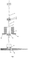
- Fig. 1 shows generally the tape tuft string 10 comprising retaining link 12, which is held under constant tension and interacts with tuft elements 14a, 14b, 14c, 14d, 14e.
- the string 10 passes through jaws 18a and 18b which are mounted on a sliding guide 16.
- the two jaws 18a and 18b operate such that they will spring open over the tuft elements 14b, 14c when drawn back up the string of tufting tapes and snap shut in a non return action.
- Two blades 20a, 20b are provided for cutting the tape and thereby separating it from the string.
- the tuft element 14a is positioned over a tufting needle 30 comprising plunger 32, recess 34 and outer tube 36.
- Fig. 1 also shows washers 38a and 38b located either side of the mattress 40, shown in section.
- the mattress 40 is in compression.
- the principal components are in place to insert the first tuft element 14a into the needle 30.
- Fig. 1a is a side view of the components 10, 12, 14, 16 and 18 in Fig. 1, and illustrates retaining link 12 held between jaws 18a and 18b, tuft element 14a being outside the jaws.
- Fig. 1b is a section along the line A-A of Fig. 1, and illustrates recess 34 cut out of the outer tube 36 of tufting needle 30.
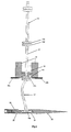
- Fig. 2 shows the jaws 18 having moved forward, drawing the string of tape tufts 10 with them and positioned such that tuft element 14a is engaged in recess 34.
- Fig. 3 shows the needle tube 36 having moved backwards with the plunger 32 remaining in place. This locks tuft element 14a in recess 34.
- Fig. 4 shows the jaws 18 having moved back past its start position up the string 10 to an intermediate position between tuft elements 14c and 14d.
- Fig. 5 shows the jaws 18 returning to the start position. Note that tuft elements 14b, 14c are in front of the start position of jaws 18.
- Fig. 6 shows the entire assembly of items 16, 18 and 20 having moved forward to provide slack in the first tape tuft 22 between tuft elements 14a and 14b.
- Fig. 7 shows the blades 20 having cut the first tape tuft 22 off the string 10 of tape tufts in between tuft elements 14b and 14c.
- the first tuft 22 is held in the needle 30.
- Fig. 8 shows the assembly 16, 18 and 20 having moved back to the start position. It also shows needle 30 and first tape tuft 22 entering mattress 40 having first passed through the washer 38a on the proximal side of mattress 40.
- Fig. 9 shows needle 30 and tape tuft 22 passing through distal washer 38b.
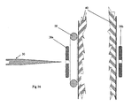
- Figs. 9 and 10 shows needle and tape tuft 22 emerging through mattress 40, having pulled the proximal washer 38a free from a unit which feeds the washers (the feed unit being shown in Fig. 15).
- Fig. 11 shows needle 30 starting to apply tension to tape tuft 22 as it continues to advance.
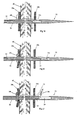
- Fig. 12 shows the tuft element 14a being ejected from needle 30 by the rearward movement of plunger 32 relative to the outer tube 36 of the needle 30. This may be assisted by having a spring (not shown) behind plunger 32, which is compressed by the tape 22 becoming taut as needle 30 continues to move forward. Alternatively, plunger 32 may be mechanically drawn backwards by any suitable means known in the art.
- Fig. 13 shows needle 30 withdrawing from mattress 40 leaving the tape tuft 22 with washers 38a, 38b threaded on each end between tuft elements 14a, 14b and the surface of the mattress 40.
- Fig. 14 shows a section of the mattress 40 uncompressed with the tape tuft 22 and washers 38 in place.
- Fig. 15 shows a possible layout of the unit with the mattress 40 having been compressed by bars 42 and some tape tufts 22 and washers 38 having already been inserted.
- the tape tuft string 10 is shown running from a reel 44 over a tensioning device 46 in to the insert and cutting device 48 (comprising, amongst other operating mechanisms, of guide 16, jaws 18 and blades 20), the needle unit mounted on mechanism 50, the washer and needle 52 with the washer feed 54 all mounted on plate 56.
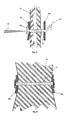
- Figs. 16 to 18 illustrate an alternative embodiment of the invention, in which local compression is applied.
- Fig. 16 shows the starting position of ring 58 between mattress 40 and washer 38a.
- Fig. 17 shows the local compression action of ring 58 and the position of the needle 30 and washer 38a, corresponding to the position between Figs. 7 and 8.
- Fig. 18 shows the continuing action of the needle 30 and associated elements. Further steps correspond to those in Figs. 9 to 14.
- these units may move in a pre-programmed X and Y axis utilising known technology. These units may also be mounted on both sides of the machine. Alternatively, the units may be mounted on the end of a robot arm. Not shown, but of a simple feeding mechanism, are the washer feeds for the second washers.
- the mattress would be inserted either manually or automatically in to the compression machine and once in place, the machine starts.
- the first action would be to compress the mattress.
- the tufting units would then proceed to move and tuft in a programmed fashion until all the tufts are in place.
- the machine would then decompress and eject the mattress.
Abstract
Description
- This invention relates to an improved method for the automatic tufting of mattresses, futons, cushions and the like. The invention also relates to a device for carrying out the method.
- Mattresses and futons have long been held together by means of tufts. The tuft also serves to stabilise the outer layers of materials, tickings and fillings.
- In the art, the word 'tuft' is generally understood to comprise two elements (hereinafter known as 'tuft elements') located outside each principal face of the mattress, and held together by means of a cord, strip or similar device (hereinafter referred to as a 'retaining link'), attached to each tuft element. Hereinafter the word 'tuft' when used alone will be used to describe the complete arrangement of tuft element, retaining link and further features.
- One particular type of tuft known in the art is the "tape tuft" 22 illustrated in Fig. 1. This tuft comprises a
strip 12 of flexible material (typically nylon, although polyethylene, polypropylene, rayon and other materials may also be used) which interacts at either end withtuft elements - Tape tufts may advantageously be produced by moulding. As illustrated in Fig. 1, a
string 10 oftufts continuous strip 12 interacting withtuft elements - Typically, such tape tufts are attached to the mattress using a needle, such as a tufting or ejector needle, the structure of which is well known to those skilled in the art. An example of a tufting needle is given in GB 903464, the contents of which are incorporated herein by reference thereto.
- The mattress is first compressed to a thickness less than the length of the tape tuft to be used. One of the tuft elements is inserted into a recess in the tufting needle, leaving the other end free. The tufting needle, carrying the first tuft element, is then passed through both faces of the mattress, the second (free) tuft element being unable to pass through the hole made by the needle and consequently remaining outside the mattress. When the tufting needle exits the mattress, the first tuft element is released so that both tuft elements are located on the outside faces of the mattress. The tufting needle may further be provided with elastic means, such as a spring-loaded plunger, which ejects or otherwise aids release of the first tuft element from the tufting needle. Once the tufting process is complete, the mattress is decompressed.
- Many manufacturers use a support, such as a washer, in connection with the tape tuft; a support may be provided on either or both faces of the mattress. The function of such supports is to prevent the tuft element from being pulled through the mattress ticking and to make the tuft more comfortable to sit or lie on. Such supports may be made from felt, cardboard, foam, leather or plastic: an alternative form of support is described in pending GB application no. 0105082.2. A first washer may be fitted to the proximal face of the mattress (ie the face the needle enters) by attaching it to the free tuft element, the washer being unable to pass through the mattress. When the needle emerges from the distal face of the mattress, its point may engage a second washer so that when the first tuft element is released from the tufting needle, the washer need only be disengaged from the needle point to be in the correct position. Alternatively, the second washer may be placed on the tuft element after it has been ejected from the tufting needle, before the mattress is decompressed.
- The tufting method described hereinabove has traditionally been carried out manually. The operator may have to apply a considerable amount of force to drive the tufting needle through the mattress. This makes the process slow and inefficient, and repeatedly applying such forces over a long period of time may be detrimental to the health of the operator.
- It would therefore be desirable to increase automation of the tufting process, making the process faster and more efficient, and less reliant on manual effort.
- Machines which allow the tufting needle to engage with driving means, such as a pneumatic piston or mechanical jack, are known in the art. The first tuft element is engaged with a recess on the tufting needle as described hereinabove, and the needle is then connected to, or forms part of, means which drive the needle through the mattress. An example of such a machine is described in GB 910253.
- EP-A-844210, which is believed to represent the closest state of the art, describes and illustrates a tufting machine including a plurality of devices, such as tufting needles, capable of receiving a tuft element and which can be positioned on a mattress at the point where the tuft is to be applied, and actuator means for pushing the tufting devices through the mattress. However, the tuft elements must be loaded manually into the tufting devices of this machine.
- As shown by the above, while the known tufting machines automate some steps of the tufting process, a significant amount of manual input is still required.
- The present invention seeks to solve the problem of providing a tufting machine and method which minimises manual input, and, in particular, avoid the need to load the tuft element manually.
- Further, the present invention seeks to provide a device capable of tufting a mattress using the string of tufts described above, without the operator having to stop the device after fitting a tuft to separate the next tuft from the string.
- Moreover, the present invention aims to provide a tufting machine capable of aiding the release of the tuft element from the tufting needle.
- In addition, the present invention seeks to solve the problem of providing a tufting machine capable of automatically placing supports (such as washers) in their correct positions.
- With the above objectives in mind, there is provided according to the invention a device for the automatic tufting of upholstery units using tufts comprising a retaining link with a tuft element at either end, said device including:
- engagement means for a tuft, said tuft being supplied from a plurality of associated tufts;
- means for separating the engaged tuft from the associated tufts;
- means for driving the engagement means, together with one tuft element and the retaining link of the engaged tuft, through an upholstery unit and withdrawing the engagement means once the tuft is released; and
- means for automatically reloading the engagement means with a further tuft.
-
- The device may further include means for aiding the release of the engaged tuft from the engagement means.
- Preferably, the device may also comprise means for engaging and correctly placing in its supporting position at least one support (such as a washer). For example, such means could take the form of feed means arranged for cooperation with the automatic tufting device.
- There is also provided according to the invention a method for the automatic tufting of upholstery units, said method including the following steps:
- providing a tuft, said tuft comprising a retaining link with a tuft element at either end and being supplied from a plurality of associated tufts;
- engaging the tuft in engagement means;
- separating the engaged tuft from the associated tufts;
- driving the engagement means, together with one tuft element and the retaining link of the engaged tuft through an upholstery unit;
- releasing the engaged tuft;
- withdrawing the engagement means; and
- automatically reloading the engagement means with a further tuft.
-
- The tuft used in the device and method according to the present invention is supplied from a plurality of associated tufts. It is preferred that the tuft is connected in a string of tufts, as described and illustrated below. In this case, the tuft may advantageously be separated from the string by cutting; for example, by means of one or more appropriately positioned blades. However, the tuft may also be associated with individual pre-cut tufts in a magazine or the like, the storage and loading of such tufts being readily apparent to those skilled in the art.
- The upholstery unit is preferably compressed throughout the process. For example, heavy bars may be provided all the way across each face of the mattress, said bars capable of moving towards one another to compress the entire upholstery unit during the process and away from one another to release the upholstery unit at the end of the process. Alternatively, local compression may be applied by the application of pressure to the surface of the upholstery unit in the specific area where the engagement means is to act upon. As the engagement means moves in concert with the application of pressure to the upholstery unit, said unit is compressed. In this case, a light mesh (typically of metal) may be used at the rear of the upholstery unit to simply support said unit during the compression and tufting process. Pressure is applied preferably by an element of annular construction. In this case, when the engagement means comprises a tufting needle, the needle with the engaged tuft element and, optionally, support, can easily pass through the hole and the point of compression is centred on the needle.
- The method may further include the step of aiding the release of the engaged tuft from the engagement means.
- The device includes means for engaging a tuft, preferably by engaging one of the tuft elements. The means for engaging a tuft preferably comprises an ejector or tufting needle as is well known to those skilled in the art, one tuft element advantageously being inserted into a recess in such a tufting needle. As outlined above, the engagement means may further be provided with means for ejecting or otherwise aiding release of the tuft element from the tufting needle. The ejection means may preferably comprise elastic means such as a spring-loaded plunger, the spring being weaker than the breaking strength of the tuft. As the engagement means moves through the upholstery unit, it is the plunger which acts upon the tuft element, taking it through the upholstery unit. The force against the plunger may be resisted by the action of a spring. When the engagement means has passed through the upholstery unit, the retaining link becomes taut; as the engagement means continues to advance, increasing pressure becomes applied to the plunger unit. In turn this increases the force on the spring such that at a load below the breaking strength of the tuft element, the load on the spring is overcome and the plunger moves rearwards relative to the body of the engagement means. This allows the tuft element to be released from the engagement means. Alternatively, driving means such as a pneumatic piston, mechanical jack or any other suitable means may be used to move or release the plunger at the appropriate position to release the tuft element at the correct location.
- The location of the tuft element in the engagement means may also be such that the action of the plunger is in the reverse sense such that the tuft element is ejected from the engagement means by the plunger pushing the tuft element from the engagement means.
- The engagement means may be connected to, or form part of, means for driving the engaged tuft element through the upholstery unit. The driving means may comprise, for example, a pneumatic piston or mechanical jack, although any means suitable for driving the tuft element through the upholstery unit may be used in the device and method according to the present invention.
- The device may be supported on any mechanical support means known in the art, for example, a supporting plate or other similar structure. Alternatively, the device may be adapted to be hand-held. It should however be noted that in such a case the device according to the present invention remains mechanically powered and operated, the operator merely holding the device in the correct position.
- A single device may be provided, the device being movable so that all sides of the upholstery unit may be tufted. Alternatively, multiple devices under common control may be provided so that several sections of the upholstery unit may be tufted at once.
- Although the present invention is hereinafter described and defined with reference to the tufting of mattresses, the person skilled in the art will understand that the invention is equally applicable to other upholstery units, such as futons and cushions for settees and chairs.
- The invention will now be described by way of example with reference to the accompanying drawings, wherein:
- Fig. 1 illustrates the principal components of the device according to the invention in their starting positions;
- Fig. 1a is a side view of part of the device illustrated in Fig. 1;
- Fig. 1b is a section along the line A-A of Fig. 1;
- Figs. 2 to 13 show the device according to the invention at further stages of the tufting process;
- Fig. 14 illustrates a section of tufted mattress at the end of the process;
- Fig. 15 is a plan view of a mattress being tufted using two devices according to the present invention; and
- Figs. 16 to 18 show the means of localised compression of a mattress in concert with the action of the device according to an alternative embodiment of the invention.
-
- Fig. 1 shows generally the
tape tuft string 10 comprising retaininglink 12, which is held under constant tension and interacts withtuft elements string 10 passes throughjaws guide 16. The twojaws tuft elements blades tuft element 14a is positioned over atufting needle 30 comprisingplunger 32,recess 34 andouter tube 36. - Fig. 1 also shows
washers mattress 40, shown in section. Themattress 40 is in compression. The principal components are in place to insert thefirst tuft element 14a into theneedle 30. - In the remaining Figures, identical components are referred to using the same reference numbers used in Fig. 1. In Figs. 1, 7-13, 15, 17 and 18, the mattress is shown in compression; in Figs. 14 and 16 it is uncompressed.
- Fig. 1a is a side view of the
components link 12 held betweenjaws tuft element 14a being outside the jaws. - Fig. 1b is a section along the line A-A of Fig. 1, and illustrates
recess 34 cut out of theouter tube 36 oftufting needle 30. - Fig. 2 shows the
jaws 18 having moved forward, drawing the string oftape tufts 10 with them and positioned such thattuft element 14a is engaged inrecess 34. - Fig. 3 shows the
needle tube 36 having moved backwards with theplunger 32 remaining in place. This lockstuft element 14a inrecess 34. - Fig. 4 shows the
jaws 18 having moved back past its start position up thestring 10 to an intermediate position betweentuft elements - Fig. 5 shows the
jaws 18 returning to the start position. Note thattuft elements jaws 18. - Fig. 6 shows the entire assembly of
items first tape tuft 22 betweentuft elements - Fig. 7 shows the blades 20 having cut the
first tape tuft 22 off thestring 10 of tape tufts in betweentuft elements first tuft 22 is held in theneedle 30. - Fig. 8 shows the
assembly needle 30 andfirst tape tuft 22 enteringmattress 40 having first passed through thewasher 38a on the proximal side ofmattress 40. - Fig. 9 shows
needle 30 andtape tuft 22 passing throughdistal washer 38b. - Figs. 9 and 10 shows needle and
tape tuft 22 emerging throughmattress 40, having pulled theproximal washer 38a free from a unit which feeds the washers (the feed unit being shown in Fig. 15). - Fig. 11 shows needle 30 starting to apply tension to
tape tuft 22 as it continues to advance. - Fig. 12 shows the
tuft element 14a being ejected fromneedle 30 by the rearward movement ofplunger 32 relative to theouter tube 36 of theneedle 30. This may be assisted by having a spring (not shown) behindplunger 32, which is compressed by thetape 22 becoming taut asneedle 30 continues to move forward. Alternatively,plunger 32 may be mechanically drawn backwards by any suitable means known in the art. - Fig. 13 shows needle 30 withdrawing from
mattress 40 leaving thetape tuft 22 withwashers tuft elements mattress 40. - Fig. 14 shows a section of the
mattress 40 uncompressed with thetape tuft 22 andwashers 38 in place. - Fig. 15 shows a possible layout of the unit with the
mattress 40 having been compressed bybars 42 and sometape tufts 22 andwashers 38 having already been inserted. Thetape tuft string 10 is shown running from areel 44 over atensioning device 46 in to the insert and cutting device 48 (comprising, amongst other operating mechanisms, ofguide 16,jaws 18 and blades 20), the needle unit mounted onmechanism 50, the washer andneedle 52 with thewasher feed 54 all mounted onplate 56. - Figs. 16 to 18 illustrate an alternative embodiment of the invention, in which local compression is applied. Fig. 16 shows the starting position of
ring 58 betweenmattress 40 andwasher 38a. - Fig. 17 shows the local compression action of
ring 58 and the position of theneedle 30 andwasher 38a, corresponding to the position between Figs. 7 and 8. - Fig. 18 shows the continuing action of the
needle 30 and associated elements. Further steps correspond to those in Figs. 9 to 14. - There may be several of these units which move in a pre-programmed X and Y axis utilising known technology. These units may also be mounted on both sides of the machine. Alternatively, the units may be mounted on the end of a robot arm. Not shown, but of a simple feeding mechanism, are the washer feeds for the second washers.
- The mattress would be inserted either manually or automatically in to the compression machine and once in place, the machine starts.
- The first action would be to compress the mattress. The tufting units would then proceed to move and tuft in a programmed fashion until all the tufts are in place. The machine would then decompress and eject the mattress.
Claims (10)
- A device for the automatic tufting of upholstery units using tufts (22) comprising a retaining link (12) with a tuft element (14a, 14b) at either end, said device including:engagement means (30, 34) for a tuft, said tuft being supplied from a plurality of associated tufts (24, 26);means (20) for separating the engaged tuft (22) from the associated tufts (24);means for driving the engagement means (30, 34), together with one tuft element (14a) and the retaining link of the engaged tuft (22), through an upholstery unit (40) and withdrawing the engagement means once the tuft is released; andmeans for automatically reloading the engagement means with a further tuft.
- A device according to claim 1, further including means (32) for aiding the release of the engaged tuft from the engagement means.
- A device according to claim 1 or claim 2, further comprising means (54) for engaging, and correctly placing in its supporting position, at least one support (38).
- A device according to claim 3, wherein the support engagement and placement means comprises feed means (54) for the support (38), said feed means (54) arranged for cooperation with the automatic tufting device.
- A device according to any one of claims 1 to 4, adapted for automatic tufting using tufts (22) connected in a string (10).
- A device according to claim 5, further comprising means (20) for cutting the tuft (22) from the string (10).
- A device according to any one of claims 1 to 4, adapted for automatic tufting using individual pre-cut tufts associated in a magazine.
- A method for the automatic tufting of an upholstery unit (40), said method including the following steps:providing a tuft (22), said tuft (22) comprising a retaining link (12) with a tuft element (14a, 14b) at either end and being supplied from a plurality of associated tufts (24, 26);engaging the tuft (22) in engagement means (30, 34);separating the engaged tuft (22) from the associated tufts (24);driving the engagement means (30, 34), together with one tuft element (14a) and the retaining link of the engaged tuft (22), through an upholstery unit (40);releasing the engaged tuft (22);withdrawing the engagement means (30, 34); andautomatically reloading the engagement means (30, 34) with a further tuft.
- A method according to claim 8, further including the step of aiding the release of the engaged tuft (22) from the engagement means (30, 34).
- A method according to claim 8 or claim 9, wherein the upholstery unit (40) is compressed during the process.
Priority Applications (1)
| Application Number | Priority Date | Filing Date | Title |
|---|---|---|---|
| EP02022086A EP1275615B1 (en) | 2000-06-20 | 2001-06-20 | Chained mattress quilting device |
Applications Claiming Priority (4)
| Application Number | Priority Date | Filing Date | Title |
|---|---|---|---|
| GB0015139 | 2000-06-20 | ||
| GB0015139A GB2363803B (en) | 2000-06-20 | 2000-06-20 | Device and method for automatically tufting upholstery |
| US10/024,390 US6718894B2 (en) | 2000-06-20 | 2001-12-21 | Device and method for automatically tufting upholstery |
| CA002366126A CA2366126C (en) | 2000-06-20 | 2001-12-21 | Device and method for automatically tufting upholstery |
Related Child Applications (1)
| Application Number | Title | Priority Date | Filing Date |
|---|---|---|---|
| EP02022086A Division EP1275615B1 (en) | 2000-06-20 | 2001-06-20 | Chained mattress quilting device |
Publications (3)
| Publication Number | Publication Date |
|---|---|
| EP1167279A2 true EP1167279A2 (en) | 2002-01-02 |
| EP1167279A3 EP1167279A3 (en) | 2003-02-05 |
| EP1167279B1 EP1167279B1 (en) | 2006-03-29 |
Family
ID=28045809
Family Applications (2)
| Application Number | Title | Priority Date | Filing Date |
|---|---|---|---|
| EP02022086A Expired - Lifetime EP1275615B1 (en) | 2000-06-20 | 2001-06-20 | Chained mattress quilting device |
| EP01305367A Expired - Lifetime EP1167279B1 (en) | 2000-06-20 | 2001-06-20 | Device and method for automatically tufting upholstery |
Family Applications Before (1)
| Application Number | Title | Priority Date | Filing Date |
|---|---|---|---|
| EP02022086A Expired - Lifetime EP1275615B1 (en) | 2000-06-20 | 2001-06-20 | Chained mattress quilting device |
Country Status (7)
| Country | Link |
|---|---|
| US (1) | US6718894B2 (en) |
| EP (2) | EP1275615B1 (en) |
| AT (2) | ATE368632T1 (en) |
| CA (1) | CA2366126C (en) |
| DE (2) | DE60129679T2 (en) |
| ES (2) | ES2261348T3 (en) |
| GB (2) | GB2371479B (en) |
Cited By (4)
| Publication number | Priority date | Publication date | Assignee | Title |
|---|---|---|---|---|
| EP1253107A1 (en) * | 2001-04-27 | 2002-10-30 | Resta S.R.L. | Apparatus for inserting tufting straps in a mattress |
| WO2003068667A1 (en) | 2002-02-14 | 2003-08-21 | Mattress Production Technology Group Limited | Automatic tufting method and apparatus therefor |
| EP1394099A1 (en) | 2002-08-29 | 2004-03-03 | Resta S.R.L. | Apparatus for inserting tuft assemblies in a mattress |
| WO2019086834A1 (en) | 2017-10-31 | 2019-05-09 | Trickett, David | Multi-length tuft feeder |
Families Citing this family (8)
| Publication number | Priority date | Publication date | Assignee | Title |
|---|---|---|---|---|
| GB0315716D0 (en) * | 2003-07-04 | 2003-08-13 | Mattress Production Technology | Method and apparatus for tufting an upholstered article |
| US7240382B2 (en) * | 2003-09-15 | 2007-07-10 | Avery Dennison Corporation | Method and tool for securing together two or more layers of a mattress using a plastic fastener |
| US20100117413A1 (en) | 2004-09-23 | 2010-05-13 | Squires Keith D | Prisoner Safety Seat and Method of Use |
| US20060061198A1 (en) * | 2004-09-23 | 2006-03-23 | Squires Keith D | Prisoner seat security device |
| ZA200703788B (en) * | 2004-10-12 | 2008-08-27 | Kingsdown Inc | Mattress construction with filamentary fasteners |
| ITBO20040767A1 (en) * | 2004-12-14 | 2005-03-14 | Resta Srl | DEVICE FOR FEEDING AN EQUIPMENT FOR THE APPLICATION OF PASSANTS IN A MATTRESS WITH DISKETS FOR GURNING THESE PASSANTS |
| US8739716B2 (en) | 2010-02-23 | 2014-06-03 | Atlanta Attachment Company | Automated quilting and tufting system |
| US10842205B2 (en) | 2016-10-20 | 2020-11-24 | Nike, Inc. | Apparel thermo-regulatory system |
Citations (4)
| Publication number | Priority date | Publication date | Assignee | Title |
|---|---|---|---|---|
| GB903464A (en) | 1960-03-08 | 1962-08-15 | Francis Philip Whaley | Improvements in tufting needles for threading mattress tuft assemblies |
| GB910253A (en) | 1960-03-29 | 1962-11-14 | Francis Philip Whaley | Apparatus for tufting mattresses, cushions and the like |
| EP0844210A2 (en) | 1996-11-22 | 1998-05-27 | Resta S.R.L. | Apparatus for fitting quilting braces to mattresses |
| GB2349332A (en) | 1999-04-27 | 2000-11-01 | Handy Limited | Tuft, upholstery and method. |
Family Cites Families (13)
| Publication number | Priority date | Publication date | Assignee | Title |
|---|---|---|---|---|
| GB814651A (en) | 1955-09-27 | 1959-06-10 | Francis Philip Whaley | Improvements in or relating to the tufting of mattresses and the like |
| GB814561A (en) | 1956-10-10 | 1959-06-10 | Abbott Lab | Penicillin salts of rosin diamines and therapeutic preparations containing same |
| US2416084A (en) * | 1943-07-19 | 1947-02-18 | Gen Motors Corp | Domestic appliance |
| GB741576A (en) * | 1953-03-02 | 1955-12-07 | Francis Philip Whaley | Improvements in or relating to tufting elements for tufting mattresses and the like |
| US3399432A (en) | 1965-12-08 | 1968-09-03 | Dennison Mfg Co | Button attachment |
| US3470834A (en) * | 1968-03-08 | 1969-10-07 | Dennison Mfg Co | Fastener attaching device |
| DE1760443B2 (en) | 1968-05-17 | 1973-11-22 | Otto P. 7061 Haubersbronn Molt | Filing button for punctiform filing of upholstery for seating and reclining furniture |
| AU498809B2 (en) * | 1973-04-04 | 1979-03-29 | Dennison Manufacturing Company | Fastener attachment |
| US4111347A (en) * | 1976-09-07 | 1978-09-05 | Dennison Manufacturing Company | Fastener attachment apparatus |
| GB1541077A (en) * | 1977-03-25 | 1979-02-21 | Watson & Ewen Ltd | Tufting needle |
| DE4121574C2 (en) * | 1991-06-29 | 1994-08-18 | Raymond A & Cie | Fastening unit for the detachable fastening of protective covers when padding foam bodies |
| KR100509071B1 (en) * | 1996-07-26 | 2005-08-18 | 케스케이드 엔지니어링 인코퍼레이티드 | System and method for fastening insulating layer to sheet material |
| US6318283B1 (en) * | 2000-07-11 | 2001-11-20 | Common Sense Systems Inc. | Method and apparatus for marking fabric |
-
2000
- 2000-06-20 GB GB0210259A patent/GB2371479B/en not_active Expired - Fee Related
- 2000-06-20 GB GB0015139A patent/GB2363803B/en not_active Expired - Fee Related
-
2001
- 2001-06-20 AT AT02022086T patent/ATE368632T1/en not_active IP Right Cessation
- 2001-06-20 AT AT01305367T patent/ATE321730T1/en not_active IP Right Cessation
- 2001-06-20 DE DE60129679T patent/DE60129679T2/en not_active Expired - Lifetime
- 2001-06-20 EP EP02022086A patent/EP1275615B1/en not_active Expired - Lifetime
- 2001-06-20 ES ES01305367T patent/ES2261348T3/en not_active Expired - Lifetime
- 2001-06-20 ES ES02022086T patent/ES2290233T3/en not_active Expired - Lifetime
- 2001-06-20 DE DE60118303T patent/DE60118303T2/en not_active Expired - Fee Related
- 2001-06-20 EP EP01305367A patent/EP1167279B1/en not_active Expired - Lifetime
- 2001-12-21 US US10/024,390 patent/US6718894B2/en not_active Expired - Lifetime
- 2001-12-21 CA CA002366126A patent/CA2366126C/en not_active Expired - Lifetime
Patent Citations (4)
| Publication number | Priority date | Publication date | Assignee | Title |
|---|---|---|---|---|
| GB903464A (en) | 1960-03-08 | 1962-08-15 | Francis Philip Whaley | Improvements in tufting needles for threading mattress tuft assemblies |
| GB910253A (en) | 1960-03-29 | 1962-11-14 | Francis Philip Whaley | Apparatus for tufting mattresses, cushions and the like |
| EP0844210A2 (en) | 1996-11-22 | 1998-05-27 | Resta S.R.L. | Apparatus for fitting quilting braces to mattresses |
| GB2349332A (en) | 1999-04-27 | 2000-11-01 | Handy Limited | Tuft, upholstery and method. |
Cited By (9)
| Publication number | Priority date | Publication date | Assignee | Title |
|---|---|---|---|---|
| EP1253107A1 (en) * | 2001-04-27 | 2002-10-30 | Resta S.R.L. | Apparatus for inserting tufting straps in a mattress |
| US6634307B2 (en) | 2001-04-27 | 2003-10-21 | Resta S.R.L. | Apparatus for inserting tufting straps in a mattress |
| WO2003068667A1 (en) | 2002-02-14 | 2003-08-21 | Mattress Production Technology Group Limited | Automatic tufting method and apparatus therefor |
| US7191716B2 (en) | 2002-02-14 | 2007-03-20 | Howard Martin Dixon | Automatic tufting method and apparatus therefor |
| EP1394099A1 (en) | 2002-08-29 | 2004-03-03 | Resta S.R.L. | Apparatus for inserting tuft assemblies in a mattress |
| WO2019086834A1 (en) | 2017-10-31 | 2019-05-09 | Trickett, David | Multi-length tuft feeder |
| GB2581093A (en) * | 2017-10-31 | 2020-08-05 | Rodgers Paul | Multi-length tuft feeder |
| GB2581093B (en) * | 2017-10-31 | 2022-05-25 | Rodgers Paul | Multi-length tuft feeder |
| US11691867B2 (en) | 2017-10-31 | 2023-07-04 | Paul Rodgers | Multi-length tuft feeder |
Also Published As
| Publication number | Publication date |
|---|---|
| ES2261348T3 (en) | 2006-11-16 |
| CA2366126A1 (en) | 2003-06-21 |
| EP1275615A3 (en) | 2003-01-29 |
| ES2290233T3 (en) | 2008-02-16 |
| GB0015139D0 (en) | 2000-08-09 |
| EP1167279A3 (en) | 2003-02-05 |
| GB0210259D0 (en) | 2002-06-12 |
| GB2363803B (en) | 2002-12-11 |
| GB2363803A (en) | 2002-01-09 |
| DE60129679T2 (en) | 2008-04-30 |
| GB2371479A (en) | 2002-07-31 |
| EP1275615A2 (en) | 2003-01-15 |
| ATE368632T1 (en) | 2007-08-15 |
| DE60118303T2 (en) | 2006-11-30 |
| CA2366126C (en) | 2009-10-27 |
| US20030116070A1 (en) | 2003-06-26 |
| EP1275615B1 (en) | 2007-08-01 |
| DE60129679D1 (en) | 2007-09-13 |
| GB2371479B (en) | 2002-12-11 |
| DE60118303D1 (en) | 2006-05-18 |
| US6718894B2 (en) | 2004-04-13 |
| ATE321730T1 (en) | 2006-04-15 |
| EP1167279B1 (en) | 2006-03-29 |
Similar Documents
| Publication | Publication Date | Title |
|---|---|---|
| EP1167279B1 (en) | Device and method for automatically tufting upholstery | |
| US4526310A (en) | Procedure and device for the application of a label to an article | |
| EP3752425A1 (en) | Portable cable tie tool | |
| JPS5828169B2 (en) | fastener assembly | |
| JPS63501410A (en) | Blind rivet installation method and device | |
| US6868797B2 (en) | Device and method for automatically tufting upholstery | |
| US9199756B2 (en) | Fastener stock and device for use in dispensing plastic fasteners therefrom | |
| JP2594701B2 (en) | Apparatus and method for separating pattern pieces from waste material | |
| US7240382B2 (en) | Method and tool for securing together two or more layers of a mattress using a plastic fastener | |
| KR100887201B1 (en) | Binding apparatus | |
| JPH0665206U (en) | Powered locking piece mounting machine | |
| JP4980924B2 (en) | Tool for fixing two or more layers of mattress with plastic fasteners | |
| US3771707A (en) | Binding device | |
| US7191716B2 (en) | Automatic tufting method and apparatus therefor | |
| US4789091A (en) | Upholstery button driver | |
| US5048265A (en) | Method and apparatus for filling cushions | |
| GB2402618A (en) | Upholstery washer | |
| JP7475152B2 (en) | Thread locking member and assembly thereof | |
| US4563390A (en) | Fabricated toy animal whisker construction and methods and apparatus for producing and applying same | |
| US20230031299A1 (en) | Baling apparatus | |
| CN218477686U (en) | Pneumatic packer body | |
| JP3795384B2 (en) | Thread holding device for multi-needle sewing machine | |
| JPH07204082A (en) | Curtain hook inserting device | |
| JP3622199B2 (en) | Nail supply mechanism for nail nailing machine | |
| JPS6130979B2 (en) |
Legal Events
| Date | Code | Title | Description |
|---|---|---|---|
| PUAI | Public reference made under article 153(3) epc to a published international application that has entered the european phase |
Free format text: ORIGINAL CODE: 0009012 |
|
| AK | Designated contracting states |
Kind code of ref document: A2 Designated state(s): AT BE CH CY DE DK ES FI FR GB GR IE IT LI LU MC NL PT SE TR |
|
| AX | Request for extension of the european patent |
Free format text: AL;LT;LV;MK;RO;SI |
|
| PUAL | Search report despatched |
Free format text: ORIGINAL CODE: 0009013 |
|
| AK | Designated contracting states |
Designated state(s): AT BE CH CY DE DK ES FI FR GB GR IE IT LI LU MC NL PT SE TR |
|
| AX | Request for extension of the european patent |
Extension state: AL LT LV MK RO SI |
|
| 17P | Request for examination filed |
Effective date: 20030625 |
|
| 17Q | First examination report despatched |
Effective date: 20030905 |
|
| AKX | Designation fees paid |
Designated state(s): AT BE CH CY DE DK ES FI FR GB GR IE IT LI LU MC NL PT SE TR |
|
| GRAP | Despatch of communication of intention to grant a patent |
Free format text: ORIGINAL CODE: EPIDOSNIGR1 |
|
| GRAS | Grant fee paid |
Free format text: ORIGINAL CODE: EPIDOSNIGR3 |
|
| GRAA | (expected) grant |
Free format text: ORIGINAL CODE: 0009210 |
|
| AK | Designated contracting states |
Kind code of ref document: B1 Designated state(s): AT BE CH CY DE DK ES FI FR GB GR IE IT LI LU MC NL PT SE TR |
|
| PG25 | Lapsed in a contracting state [announced via postgrant information from national office to epo] |
Ref country code: AT Free format text: LAPSE BECAUSE OF FAILURE TO SUBMIT A TRANSLATION OF THE DESCRIPTION OR TO PAY THE FEE WITHIN THE PRESCRIBED TIME-LIMIT Effective date: 20060329 Ref country code: NL Free format text: LAPSE BECAUSE OF FAILURE TO SUBMIT A TRANSLATION OF THE DESCRIPTION OR TO PAY THE FEE WITHIN THE PRESCRIBED TIME-LIMIT Effective date: 20060329 Ref country code: LI Free format text: LAPSE BECAUSE OF FAILURE TO SUBMIT A TRANSLATION OF THE DESCRIPTION OR TO PAY THE FEE WITHIN THE PRESCRIBED TIME-LIMIT Effective date: 20060329 Ref country code: CH Free format text: LAPSE BECAUSE OF FAILURE TO SUBMIT A TRANSLATION OF THE DESCRIPTION OR TO PAY THE FEE WITHIN THE PRESCRIBED TIME-LIMIT Effective date: 20060329 |
|
| REG | Reference to a national code |
Ref country code: GB Ref legal event code: FG4D |
|
| REG | Reference to a national code |
Ref country code: CH Ref legal event code: EP |
|
| REG | Reference to a national code |
Ref country code: IE Ref legal event code: FG4D |
|
| REF | Corresponds to: |
Ref document number: 60118303 Country of ref document: DE Date of ref document: 20060518 Kind code of ref document: P |
|
| PGFP | Annual fee paid to national office [announced via postgrant information from national office to epo] |
Ref country code: MC Payment date: 20060526 Year of fee payment: 6 |
|
| REG | Reference to a national code |
Ref country code: GR Ref legal event code: EP Ref document number: 20060401237 Country of ref document: GR |
|
| PGFP | Annual fee paid to national office [announced via postgrant information from national office to epo] |
Ref country code: NL Payment date: 20060604 Year of fee payment: 6 |
|
| PGFP | Annual fee paid to national office [announced via postgrant information from national office to epo] |
Ref country code: CH Payment date: 20060614 Year of fee payment: 6 Ref country code: FI Payment date: 20060614 Year of fee payment: 6 |
|
| PGFP | Annual fee paid to national office [announced via postgrant information from national office to epo] |
Ref country code: DK Payment date: 20060621 Year of fee payment: 6 |
|
| PGFP | Annual fee paid to national office [announced via postgrant information from national office to epo] |
Ref country code: LU Payment date: 20060628 Year of fee payment: 6 |
|
| PG25 | Lapsed in a contracting state [announced via postgrant information from national office to epo] |
Ref country code: SE Free format text: LAPSE BECAUSE OF FAILURE TO SUBMIT A TRANSLATION OF THE DESCRIPTION OR TO PAY THE FEE WITHIN THE PRESCRIBED TIME-LIMIT Effective date: 20060629 Ref country code: DK Free format text: LAPSE BECAUSE OF FAILURE TO SUBMIT A TRANSLATION OF THE DESCRIPTION OR TO PAY THE FEE WITHIN THE PRESCRIBED TIME-LIMIT Effective date: 20060629 |
|
| PG25 | Lapsed in a contracting state [announced via postgrant information from national office to epo] |
Ref country code: PT Free format text: LAPSE BECAUSE OF FAILURE TO SUBMIT A TRANSLATION OF THE DESCRIPTION OR TO PAY THE FEE WITHIN THE PRESCRIBED TIME-LIMIT Effective date: 20060829 |
|
| REG | Reference to a national code |
Ref country code: CH Ref legal event code: PL |
|
| NLV1 | Nl: lapsed or annulled due to failure to fulfill the requirements of art. 29p and 29m of the patents act | ||
| ET | Fr: translation filed | ||
| REG | Reference to a national code |
Ref country code: ES Ref legal event code: FG2A Ref document number: 2261348 Country of ref document: ES Kind code of ref document: T3 |
|
| PLBE | No opposition filed within time limit |
Free format text: ORIGINAL CODE: 0009261 |
|
| STAA | Information on the status of an ep patent application or granted ep patent |
Free format text: STATUS: NO OPPOSITION FILED WITHIN TIME LIMIT |
|
| 26N | No opposition filed |
Effective date: 20070102 |
|
| PG25 | Lapsed in a contracting state [announced via postgrant information from national office to epo] |
Ref country code: MC Free format text: LAPSE BECAUSE OF NON-PAYMENT OF DUE FEES Effective date: 20070630 |
|
| PG25 | Lapsed in a contracting state [announced via postgrant information from national office to epo] |
Ref country code: FI Free format text: LAPSE BECAUSE OF FAILURE TO SUBMIT A TRANSLATION OF THE DESCRIPTION OR TO PAY THE FEE WITHIN THE PRESCRIBED TIME-LIMIT Effective date: 20060329 |
|
| PGFP | Annual fee paid to national office [announced via postgrant information from national office to epo] |
Ref country code: TR Payment date: 20080528 Year of fee payment: 8 |
|
| PGFP | Annual fee paid to national office [announced via postgrant information from national office to epo] |
Ref country code: DE Payment date: 20080626 Year of fee payment: 8 Ref country code: ES Payment date: 20080717 Year of fee payment: 8 |
|
| PG25 | Lapsed in a contracting state [announced via postgrant information from national office to epo] |
Ref country code: CY Free format text: LAPSE BECAUSE OF FAILURE TO SUBMIT A TRANSLATION OF THE DESCRIPTION OR TO PAY THE FEE WITHIN THE PRESCRIBED TIME-LIMIT Effective date: 20060329 |
|
| PGFP | Annual fee paid to national office [announced via postgrant information from national office to epo] |
Ref country code: FR Payment date: 20080617 Year of fee payment: 8 |
|
| PGFP | Annual fee paid to national office [announced via postgrant information from national office to epo] |
Ref country code: BE Payment date: 20080814 Year of fee payment: 8 |
|
| PGFP | Annual fee paid to national office [announced via postgrant information from national office to epo] |
Ref country code: GR Payment date: 20080515 Year of fee payment: 8 |
|
| PG25 | Lapsed in a contracting state [announced via postgrant information from national office to epo] |
Ref country code: LU Free format text: LAPSE BECAUSE OF NON-PAYMENT OF DUE FEES Effective date: 20070620 |
|
| BERE | Be: lapsed |
Owner name: *WHALEY JONATHON NICHOLAS Effective date: 20090630 |
|
| REG | Reference to a national code |
Ref country code: FR Ref legal event code: ST Effective date: 20100226 |
|
| PG25 | Lapsed in a contracting state [announced via postgrant information from national office to epo] |
Ref country code: FR Free format text: LAPSE BECAUSE OF NON-PAYMENT OF DUE FEES Effective date: 20090630 |
|
| PG25 | Lapsed in a contracting state [announced via postgrant information from national office to epo] |
Ref country code: DE Free format text: LAPSE BECAUSE OF NON-PAYMENT OF DUE FEES Effective date: 20100101 Ref country code: BE Free format text: LAPSE BECAUSE OF NON-PAYMENT OF DUE FEES Effective date: 20090630 |
|
| REG | Reference to a national code |
Ref country code: ES Ref legal event code: FD2A Effective date: 20090622 |
|
| PG25 | Lapsed in a contracting state [announced via postgrant information from national office to epo] |
Ref country code: GR Free format text: LAPSE BECAUSE OF NON-PAYMENT OF DUE FEES Effective date: 20100107 Ref country code: ES Free format text: LAPSE BECAUSE OF NON-PAYMENT OF DUE FEES Effective date: 20090622 |
|
| PG25 | Lapsed in a contracting state [announced via postgrant information from national office to epo] |
Ref country code: TR Free format text: LAPSE BECAUSE OF NON-PAYMENT OF DUE FEES Effective date: 20090620 |
|
| PGFP | Annual fee paid to national office [announced via postgrant information from national office to epo] |
Ref country code: IT Payment date: 20190620 Year of fee payment: 19 Ref country code: IE Payment date: 20190610 Year of fee payment: 19 |
|
| PGFP | Annual fee paid to national office [announced via postgrant information from national office to epo] |
Ref country code: GB Payment date: 20190619 Year of fee payment: 19 |
|
| GBPC | Gb: european patent ceased through non-payment of renewal fee |
Effective date: 20200620 |
|
| PG25 | Lapsed in a contracting state [announced via postgrant information from national office to epo] |
Ref country code: GB Free format text: LAPSE BECAUSE OF NON-PAYMENT OF DUE FEES Effective date: 20200620 Ref country code: IE Free format text: LAPSE BECAUSE OF NON-PAYMENT OF DUE FEES Effective date: 20200620 |
|
| PG25 | Lapsed in a contracting state [announced via postgrant information from national office to epo] |
Ref country code: IT Free format text: LAPSE BECAUSE OF NON-PAYMENT OF DUE FEES Effective date: 20200620 |