WO2021153483A1 - 工作機械の制御装置 - Google Patents
工作機械の制御装置 Download PDFInfo
- Publication number
- WO2021153483A1 WO2021153483A1 PCT/JP2021/002379 JP2021002379W WO2021153483A1 WO 2021153483 A1 WO2021153483 A1 WO 2021153483A1 JP 2021002379 W JP2021002379 W JP 2021002379W WO 2021153483 A1 WO2021153483 A1 WO 2021153483A1
- Authority
- WO
- WIPO (PCT)
- Prior art keywords
- swing
- command
- tool
- phase
- control device
- Prior art date
- Legal status (The legal status is an assumption and is not a legal conclusion. Google has not performed a legal analysis and makes no representation as to the accuracy of the status listed.)
- Ceased
Links
Images






Classifications
-
- B—PERFORMING OPERATIONS; TRANSPORTING
- B23—MACHINE TOOLS; METAL-WORKING NOT OTHERWISE PROVIDED FOR
- B23Q—DETAILS, COMPONENTS, OR ACCESSORIES FOR MACHINE TOOLS, e.g. ARRANGEMENTS FOR COPYING OR CONTROLLING; MACHINE TOOLS IN GENERAL CHARACTERISED BY THE CONSTRUCTION OF PARTICULAR DETAILS OR COMPONENTS; COMBINATIONS OR ASSOCIATIONS OF METAL-WORKING MACHINES, NOT DIRECTED TO A PARTICULAR RESULT
- B23Q15/00—Automatic control or regulation of feed movement, cutting velocity or position of tool or work
- B23Q15/007—Automatic control or regulation of feed movement, cutting velocity or position of tool or work while the tool acts upon the workpiece
- B23Q15/12—Adaptive control, i.e. adjusting itself to have a performance which is optimum according to a preassigned criterion
-
- G—PHYSICS
- G05—CONTROLLING; REGULATING
- G05B—CONTROL OR REGULATING SYSTEMS IN GENERAL; FUNCTIONAL ELEMENTS OF SUCH SYSTEMS; MONITORING OR TESTING ARRANGEMENTS FOR SUCH SYSTEMS OR ELEMENTS
- G05B19/00—Program-control systems
- G05B19/02—Program-control systems electric
- G05B19/18—Numerical control [NC], i.e. automatically operating machines, in particular machine tools, e.g. in a manufacturing environment, so as to execute positioning, movement or co-ordinated operations by means of program data in numerical form
- G05B19/4093—Numerical control [NC], i.e. automatically operating machines, in particular machine tools, e.g. in a manufacturing environment, so as to execute positioning, movement or co-ordinated operations by means of program data in numerical form characterised by part programming, e.g. entry of geometrical information as taken from a technical drawing, combining this with machining and material information to obtain control information, named part program, for the NC machine
-
- B—PERFORMING OPERATIONS; TRANSPORTING
- B23—MACHINE TOOLS; METAL-WORKING NOT OTHERWISE PROVIDED FOR
- B23B—TURNING; BORING
- B23B35/00—Methods for boring or drilling, or for working essentially requiring the use of boring or drilling machines; Use of auxiliary equipment in connection with such methods
-
- B—PERFORMING OPERATIONS; TRANSPORTING
- B23—MACHINE TOOLS; METAL-WORKING NOT OTHERWISE PROVIDED FOR
- B23B—TURNING; BORING
- B23B47/00—Constructional features of components specially designed for boring or drilling machines; Accessories therefor
- B23B47/34—Arrangements for removing chips out of the holes made; Chip- breaking arrangements attached to the tool
-
- B—PERFORMING OPERATIONS; TRANSPORTING
- B23—MACHINE TOOLS; METAL-WORKING NOT OTHERWISE PROVIDED FOR
- B23Q—DETAILS, COMPONENTS, OR ACCESSORIES FOR MACHINE TOOLS, e.g. ARRANGEMENTS FOR COPYING OR CONTROLLING; MACHINE TOOLS IN GENERAL CHARACTERISED BY THE CONSTRUCTION OF PARTICULAR DETAILS OR COMPONENTS; COMBINATIONS OR ASSOCIATIONS OF METAL-WORKING MACHINES, NOT DIRECTED TO A PARTICULAR RESULT
- B23Q15/00—Automatic control or regulation of feed movement, cutting velocity or position of tool or work
- B23Q15/007—Automatic control or regulation of feed movement, cutting velocity or position of tool or work while the tool acts upon the workpiece
- B23Q15/013—Control or regulation of feed movement
-
- B—PERFORMING OPERATIONS; TRANSPORTING
- B23—MACHINE TOOLS; METAL-WORKING NOT OTHERWISE PROVIDED FOR
- B23Q—DETAILS, COMPONENTS, OR ACCESSORIES FOR MACHINE TOOLS, e.g. ARRANGEMENTS FOR COPYING OR CONTROLLING; MACHINE TOOLS IN GENERAL CHARACTERISED BY THE CONSTRUCTION OF PARTICULAR DETAILS OR COMPONENTS; COMBINATIONS OR ASSOCIATIONS OF METAL-WORKING MACHINES, NOT DIRECTED TO A PARTICULAR RESULT
- B23Q17/00—Arrangements for observing, indicating or measuring on machine tools
- B23Q17/09—Arrangements for observing, indicating or measuring on machine tools for indicating or measuring cutting pressure or for determining cutting-tool condition, e.g. cutting ability, load on tool
- B23Q17/0952—Arrangements for observing, indicating or measuring on machine tools for indicating or measuring cutting pressure or for determining cutting-tool condition, e.g. cutting ability, load on tool during machining
-
- B—PERFORMING OPERATIONS; TRANSPORTING
- B23—MACHINE TOOLS; METAL-WORKING NOT OTHERWISE PROVIDED FOR
- B23Q—DETAILS, COMPONENTS, OR ACCESSORIES FOR MACHINE TOOLS, e.g. ARRANGEMENTS FOR COPYING OR CONTROLLING; MACHINE TOOLS IN GENERAL CHARACTERISED BY THE CONSTRUCTION OF PARTICULAR DETAILS OR COMPONENTS; COMBINATIONS OR ASSOCIATIONS OF METAL-WORKING MACHINES, NOT DIRECTED TO A PARTICULAR RESULT
- B23Q17/00—Arrangements for observing, indicating or measuring on machine tools
- B23Q17/09—Arrangements for observing, indicating or measuring on machine tools for indicating or measuring cutting pressure or for determining cutting-tool condition, e.g. cutting ability, load on tool
- B23Q17/0952—Arrangements for observing, indicating or measuring on machine tools for indicating or measuring cutting pressure or for determining cutting-tool condition, e.g. cutting ability, load on tool during machining
- B23Q17/0961—Arrangements for observing, indicating or measuring on machine tools for indicating or measuring cutting pressure or for determining cutting-tool condition, e.g. cutting ability, load on tool during machining by measuring power, current or torque of a motor
-
- G—PHYSICS
- G05—CONTROLLING; REGULATING
- G05B—CONTROL OR REGULATING SYSTEMS IN GENERAL; FUNCTIONAL ELEMENTS OF SUCH SYSTEMS; MONITORING OR TESTING ARRANGEMENTS FOR SUCH SYSTEMS OR ELEMENTS
- G05B2219/00—Program-control systems
- G05B2219/30—Nc systems
- G05B2219/45—Nc applications
- G05B2219/45129—Boring, drilling
-
- Y—GENERAL TAGGING OF NEW TECHNOLOGICAL DEVELOPMENTS; GENERAL TAGGING OF CROSS-SECTIONAL TECHNOLOGIES SPANNING OVER SEVERAL SECTIONS OF THE IPC; TECHNICAL SUBJECTS COVERED BY FORMER USPC CROSS-REFERENCE ART COLLECTIONS [XRACs] AND DIGESTS
- Y10—TECHNICAL SUBJECTS COVERED BY FORMER USPC
- Y10T—TECHNICAL SUBJECTS COVERED BY FORMER US CLASSIFICATION
- Y10T408/00—Cutting by use of rotating axially moving tool
- Y10T408/16—Cutting by use of rotating axially moving tool with control means energized in response to activator stimulated by condition sensor
- Y10T408/17—Cutting by use of rotating axially moving tool with control means energized in response to activator stimulated by condition sensor to control infeed
- Y10T408/173—Responsive to work
-
- Y—GENERAL TAGGING OF NEW TECHNOLOGICAL DEVELOPMENTS; GENERAL TAGGING OF CROSS-SECTIONAL TECHNOLOGIES SPANNING OVER SEVERAL SECTIONS OF THE IPC; TECHNICAL SUBJECTS COVERED BY FORMER USPC CROSS-REFERENCE ART COLLECTIONS [XRACs] AND DIGESTS
- Y10—TECHNICAL SUBJECTS COVERED BY FORMER USPC
- Y10T—TECHNICAL SUBJECTS COVERED BY FORMER US CLASSIFICATION
- Y10T408/00—Cutting by use of rotating axially moving tool
- Y10T408/23—Cutting by use of rotating axially moving tool including means to cause Tool to progressively vibrate toward work
Definitions
- This disclosure relates to a machine tool control device.
- a cutting tool hereinafter referred to as a tool.
- a tool drilling using a drill
- steps feed or pecking return operation
- Patent Documents 1 to 3 a technique for cutting a workpiece while vibrating the tool in the feed direction at a low frequency is known (see, for example, Patent Documents 1 to 3). According to these techniques, it is possible to execute the cutting process while dividing the chips generated by the cutting process, and it is said that the processing accuracy, workability and tool life can be improved.
- Patent Document 1 describes that the feed rate of the position command is changed, the reduction of the shock at the time of cutting is not considered.
- Patent Document 2 although it is described that the speed is changed by the reciprocation of the swing, the reduction of the shock at the time of cutting is considered only by switching the reciprocation at a predetermined spindle angle. It has not been.
- Patent Document 3 describes that the feed rate is increased or decreased within a range in which the tool does not retract, and it is said that this has the effect of reducing the shock at the time of cutting.
- the tool since the tool is not retracted, it is difficult to discharge chips, and there is a possibility that machining defects may occur due to entanglement of chips in the tool.
- One aspect of the present disclosure is to control a spindle that relatively rotates a cutting tool and a work, and control a feed shaft that moves the cutting tool and the work while relatively swinging in the feed direction.
- This is a control device for a machine tool that executes cutting, and generates a swing command that swings the cutting tool and the work relatively in the feed direction based on predetermined swing conditions.
- the feed is based on a position command or a superposition command generated by superimposing a swing command generated by the swing command generation unit on a position command or a position deviation which is a difference between the position command and the position feedback.
- a control unit for controlling an electric motor for driving a shaft is provided, and the swing command generation unit is provided with a swing command based on a swing phase or time calculated based on the predetermined swing condition.
- a machine tool control device that changes at least one of the phase advancement method and the amplitude of the swing command.
- a machine tool control device capable of reliably dividing and discharging chips and suppressing damage to the tool by reducing the shock when the tool cuts into the work.
- FIG. 1 is a diagram showing drilling according to an embodiment of the present disclosure.
- a drill is used as the tool T to drill a hole in the work W.
- the tool T and the work W are relatively rotated, and the tool T and the work W are relatively swung in the feed direction to make a hole. , Chips can be separated.
- the work W is fixed and the tool T is moved by the feed shaft while being rotated by the spindle will be described.
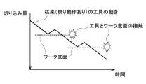
- FIG. 2 is a diagram showing the movement of a tool in conventional drilling.
- the tool T moves in a direction temporarily separated from the bottom surface of the hole being machined (hereinafter referred to as the bottom surface of the work) by the return motion in the feed direction. ..
- the chips are divided.
- the tool T comes into contact with the bottom surface of the work by the cutting operation of moving in the direction approaching the work W again, and the cutting is restarted.
- a shock is generated by the contact between the tool T and the bottom surface of the work.
- the reduction of this shock has not been considered, and as shown in FIG. 2, the speed (tilt) of the tool is constant, so that a large shock is generated.
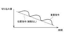
- FIG. 3 is a diagram showing the movement of the tool T in the drilling according to the present embodiment.
- a superimposition command generated by adding a sinusoidal swing command to the position command (hereinafter referred to as superimposition) as described in detail later.
- the tool T operates according to the procedure. Specifically, since the tool T swings in the feed direction, the tool T moves in a direction temporarily separated from the bottom surface of the work by a backward operation (hereinafter, also referred to as a return motion) in the feed direction. At this time, the chips are divided.
- the forward movement in the feed direction causes the work to come into contact with the bottom surface again to restart the cutting.
- the sinusoidal swing phase and / or swing amplitude is changed between the forward motion and the reverse motion, so that the tool is as shown in FIG.
- the speed (tilt) of can be changed. Therefore, the speed of the tool at the time of cutting can be slowed down, and the shock at the time of cutting can be reduced.
- the machine tool control device 100 controls a spindle motor (not shown) that rotates the tool T and the work W relatively, and causes the tool T and the work W to be relatively fed in the feed direction. Drilling is performed by controlling the motor 30 of the feed shaft that moves while swinging.
- the machine tool control device 100 according to the present embodiment is realized by, for example, causing a computer having a CPU, a memory, or the like to read a program for executing drilling according to the present embodiment.
- FIG. 4 is a functional block diagram of the machine tool control device 100 according to the present embodiment.
- the machine tool control device 100 includes a position command creation unit 21, a storage unit 22, a servo control device 10, adders 11 and 13, and an accumulator 12.
- a learning control unit 14, a position / speed control unit 15, a swing command generation unit 16, and a load acquisition unit 17 are provided.
- the position command creation unit 21 creates a position command. Specifically, the position command creating unit 21 creates a position command for the motor 30 of the feed shaft by analyzing the machining program stored in the storage unit 22 described later.
- the adder 11 calculates the position deviation. Specifically, the adder 11 provides position feedback based on position detection by an encoder (not shown) provided in the motor 30 of the feed shaft, and the position command creation unit 21. Calculate the position deviation, which is the difference between the position command of the feed axis created in.
- the integrator 12 calculates the integrated value of the position deviation. Specifically, the integrator 12 calculates the integrated value of the position deviation by integrating the position deviation calculated by the adder 11.
- the adder 13 calculates a superposition command. Specifically, the adder 13 adds (superimposes) a swing command generated by the swing command generation unit 16, which will be described later, to the integrated value of the position deviation calculated by the totalizer 12. , Generate a superposition command. The method of generating the superimposition command will be described in detail later.
- the learning control unit 14 calculates the correction amount of the superimposition command based on the above position deviation, and corrects the superimposition command by adding the calculated correction amount to the superimposition command. More specifically, the learning control unit 14 repeatedly calculates the periodic correction amount based on the periodic superimposition command. Specifically, the learning control unit 14 stores the deviation between the ideal position and the actual position of the motor 30 which has a memory and can define a certain period in the memory, and reads out the deviation stored in the memory for each cycle. Calculates the correction amount for bringing the deviation closer to 0, and superimposes the calculated correction amount on the superimposition command for correction.
- the superimposition command of the present embodiment is likely to cause a position deviation due to the inclusion of the swing command, but the correction by the learning control unit 14 improves the followability to the periodic swing command.
- the learning control unit 14 preferably stores the superimposition command and the phase of the swing command in a memory in association with each other, and corrects the superimposition command based on the correspondence between the stored superimposition command and the phase of the swing command. Is calculated. As a result, the followability to the periodic swing command is further improved.
- the position / speed control unit 15 generates a torque command for the motor 30 that drives the feed shaft based on the corrected superposition command, and controls the motor 30 by the generated torque command. As a result, the motor 30 that drives the feed shaft reaches the command position with rocking.
- the swing command generation unit 16 generates a swing command that swings the tool T and the work W relatively in the feed direction based on a predetermined swing condition.
- the swing command generation unit 16 includes a swing phase calculation unit 163, a swing amplitude calculation unit 161 and a swing command calculation unit 162.
- the swing phase calculation unit 163 calculates the reference phase (not shown) based on the predetermined swing condition, and calculates the swing phase by multiplying the time or the reference phase by the rate of change based on the predetermined swing condition.
- the swing amplitude calculation unit 161 calculates the swing amplitude based on a predetermined swing condition.
- the swing command calculation unit 162 calculates the swing command based on the swing phase calculated by the swing phase calculation unit 163 and the swing amplitude calculated by the swing amplitude calculation unit 161.
- the predetermined swing conditions are the swing phase information, the swing amplitude information, the time, and the relative rotation speed of the tool T and the work W that can be acquired from the machining program stored in the storage unit 22 described later. ..
- the swing command generation unit 16 generates a swing command based on the swing phase information and the swing amplitude information.
- the swing phase calculation unit 163 determines the rate of change of the swing phase calculated based on a predetermined swing condition so that the machining load of the tool T acquired by the load acquisition unit 17, which will be described later, is preferably reduced. change.
- the swing amplitude calculation unit 161 preferably calculates the swing amplitude based on a predetermined swing condition so that the machining load of the tool T acquired by the load acquisition unit 17, which will be described later, is reduced. change.
- the swing phase and swing amplitude can be changed according to the increase or decrease in the machining load, and the shock at the time of cutting can be further reduced.
- the swing command generation unit 16 determines how to advance the phase of the swing command and the swing command based on the time or the reference phase calculated based on the predetermined swing condition. Change at least one of the amplitudes.
- the change in the way of advancing the phase of the swing command includes at least a change in the rate of change of the swing phase, and may also include a change in the swing amplitude.
- the swing command generation unit 16 changes at least one of the phase advance of the swing command and the amplitude of the swing command, preferably based on the tool information.
- the tool information is stored in the storage unit 22 described later.
- the tool information includes the specifications of the tool T including the number of blades of the tool T, the diameter of the tool T, and the like. For example, when the ratio of the machining depth to the tool diameter is equal to or greater than a predetermined value, the chip evacuation property can be improved by increasing the rate of change of the swing phase. Further, for example, as the number of blades of the tool T is large, the trajectories of the blades are likely to overlap and air cut is likely to occur. Therefore, the rate of change of the swing phase is increased or the swing amplitude is reduced. Also, the chips can be fragmented. The relationship between the number of blades of the tool T and the swing command will be described in detail later.
- the swing command generation unit 16 preferably synchronizes the phase of the swing command with the phase of the spindle that relatively rotates the tool T and the work W. For example, when the number of blades of the tool T is large, the space between the blades is narrow and the chip discharge property is poor. However, by synchronizing the phase of the swing command with the phase of the spindle, the chip discharge property can be improved. The synchronization between the phase of the swing command and the phase of the spindle will be described in detail later.
- the storage unit 22 stores the tool information related to the tool T (the specification of the tool T including the number of blades of the tool T, the diameter of the tool T, etc.), the machining program, and the swing phase information (for example, the swing phase) that can be acquired from the machining program.
- Information such as rate of change), swing amplitude information (for example, swing amplitude magnification), time, and the number of relative rotations of the tool T and the work W (spindle rotation) is stored.
- the load acquisition unit 17 acquires the machining load generated in the tool T during cutting. Specifically, the load acquisition unit 17 acquires the machining load received by the tool T during cutting from the superimposition command or the current value or torque command of the motor 30.
- FIG. 5 is a diagram showing the rate of change of the swing phase of the drilling according to the present embodiment.
- FIG. 6 is a diagram showing a swing phase of drilling according to the present embodiment.
- FIG. 7 is a diagram showing a swing command for drilling according to the present embodiment.
- FIG. 8 is a diagram showing a superimposition command for drilling according to the present embodiment.
- Swing command (K ⁇ F / 2) ⁇ cos (2 ⁇ ⁇ I ⁇ t)-(K ⁇ F / 2) ⁇ ⁇ ⁇ (1)
- K is the multiplication factor of the swing amplitude with respect to the movement amount of the tool
- F is the movement amount of the tool, that is, the feed amount per rotation [mm / one rotation of the spindle]
- I is the unit time. It is the rate of change of the swing phase
- t is the time [s].
- (K ⁇ F / 2) is the swing amplitude
- (2 ⁇ ⁇ I ⁇ t) is the swing phase
- ⁇ (K ⁇ F / 2) is extra for the command position during normal cutting without swing. Represents the offset for not cutting into.
- the superposition command is shown in FIGS. 5 to 8. It is generated so that it can be used.
- I 1 and I 2 may be designated directly from a predetermined frequency, respectively, or I 1 may be designated as 1 and I 2 may be designated as a magnification for multiplying a predetermined frequency.
- the rate of change of the swing phase changes from I 1 to a larger I 2 between t 1 and t 2 .
- the rate of change (frequency) of the swing phase is larger than that of other times, and the slope of the swing phase becomes larger. You can see that there is.
- the swing command generated at this time is a sinusoidal swing command as shown in FIG. 7, and the rate of change (frequency) of the swing phase between t 1 and t 2 is also shown in this figure. It turns out that is large.
- the superimposition command in which the swing command shown in FIG. 7 is superposed on the position command (without swing) becomes a sinusoidal superimposition command as shown in FIG. As described above, the superimposition command is generated.
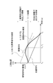
- FIG. 9 is a diagram showing a superposition command capable of reducing a shock at the time of cutting.
- FIG. 10 is a diagram showing a superposition command that cannot reduce the shock at the time of cutting.
- ti is the time at the moment when the tool T and the work W come into contact with each other.
- FIG. 9 shows a superposition command when a shock reduction condition is set from the speed.
- the speed of the superposition command is the same as the position command (not including the swing command). This rate is, in FIG. 9, indicated by the slope of the curve of the superimposed instruction in t 1.
- the term including sin in the following mathematical formula (5) which is the formula of the velocity of the superposition command, is 0.
- the speed at this time is the same as the normal cutting speed as shown by the following mathematical formula (3).
- the shock can be reduced and the tool life can be extended as compared with the conventional normal step machining or the like. I can say.
- command position F [mm / spindle 1 rotation] x S [spindle 1 rotation / minute] x t [seconds] / 60 ...
- command speed F ⁇ S / 60 ⁇ ⁇ ⁇ (3)
- Command position F ⁇ S ⁇ t / 60 + (K ⁇ F / 2) ⁇ cos (2 ⁇ ⁇ I ⁇ t)-(K ⁇ F / 2) ...
- Command speed F ⁇ S / 60- ( ⁇ ⁇ I ⁇ K ⁇ F) ⁇ sin (2 ⁇ ⁇ I ⁇ t) ⁇ ⁇ ⁇ (5)
- Command acceleration -2 ⁇ 2 x I 2 x K x F x cos (2 ⁇ x I x t) ...
- Command jerk 4 ⁇ 3 ⁇ I 3 ⁇ K ⁇ F ⁇ sin (2 ⁇ ⁇ I ⁇ t) ⁇ ⁇ ⁇ (7)
- the shock at the time of cutting can be reduced.
- F ⁇ S / 60> F ⁇ S / 60- ( ⁇ ⁇ I ⁇ K ⁇ F) ⁇ sin (2 ⁇ ⁇ I ⁇ t) may be satisfied. If 0 ⁇ I ⁇ t ⁇ 0.5, the term including sin is negative, so the speed is slower than that of normal cutting.
- the machine tool control device 100 can determine the machined region from the position feedback of the motor 30 and also knows how to advance the swing phase, the time when the tool T operated by the superposition command collides with the work W is obtained. be able to. Therefore, the shock can be reduced by changing I so as to satisfy the above inequality at that time.
- the shock reduction condition may be set by suppressing the acceleration of the tool T during machining.
- the values of I and K are set so that the jerk 4 ⁇ 3 ⁇ I 3 ⁇ K ⁇ F ⁇ sin (2 ⁇ ⁇ I ⁇ t) is minimized in the entire swing, and the feed shaft including the tool T is included.
- the shock received by the entire machine due to the swing of the drive unit may be reduced.
- FIG. 11 is a diagram showing the loci of each blade when the number of blades of the tool T is 2.
- FIG. 12 is a diagram showing a locus of each blade when the number of blades of the tool T is 3.
- Swing command (K ⁇ F / 2) ⁇ cos (2 ⁇ ⁇ S ⁇ I ′ ⁇ t / 60)-(K ⁇ F / 2) ... (8)
- S is the rotation speed [minute- 1 ] or [rpm] of the spindle
- I' represents the rate of change of the swing phase per rotation of the spindle.
- F, K, and t are the same as the above-mentioned mathematical formula (1). Even when the swing phase and the spindle rotation phase are synchronized, the superimposition command can be created in the same manner as when the swing phase and the spindle rotation phase are not synchronized.
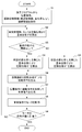
- FIG. 13 is a flowchart showing a procedure for drilling according to the present embodiment when the method of advancing the swing phase is changed based on the reference phase.
- step S1 position command, frequency information , swing phase information including change rates I 1 and I 2 , and swing amplitude information are acquired from the machining program.
- step S2 the reference phase ⁇ is calculated from the acquired frequency information and updated.
- the reference phase ⁇ may be calculated so as to synchronize with the spindle phase instead of the frequency information.
- step S3 it is determined whether or not the calculated reference phase ⁇ is equal to or greater than a predetermined threshold value. If this determination is YES, the swing phase ⁇ 'is calculated (updated) from the reference phase ⁇ multiplied by the rate of change I 1 in step S4. If this determination is NO, the swing phase ⁇ 'is calculated (updated) from the reference phase ⁇ multiplied by the rate of change I 2 in step S5.
- step S6 a swing command is generated based on the swing phase ⁇ 'and the swing amplitude, and in step S7, the swing command is added (superimposed) to the position command to generate a superposition command.
- the method of generating the swing command and the superimposition command is as described above.
- step S8 the motor 30 that drives the feed shaft is operated by the superposition command generated in step S7, and in step S8, it is determined whether or not the motor 30 has reached the command position. If this determination is NO, the process returns to step S2 and the main process is executed again. If YES, the main process ends.
- a swing command generation unit 16 for generating a swing command that swings the tool T and the work W relatively in the feed direction based on a predetermined swing condition is provided, and a predetermined swing is provided. It is configured to change at least one of the swing command phase advance and the swing command amplitude based on the swing phase calculated based on the dynamic conditions or the time.
- the phase advancement method that is, the frequency and the amplitude can be changed between the forward movement and the reverse movement within one cycle of the swing operation, whereby the chips can be reliably divided and discharged.
- the swing phase per hour in the section from when the sine wave swing command is superimposed on the cutting feed command at a constant speed and the tool T retracts due to the superposition command until it comes into contact with the work W again, the swing phase per hour.
- the rate of change can be multiplied by a predetermined magnification to slow down the phase advance.
- the first frequency information and the second frequency information can be specified in the machining program and switched in the above section to slow down the phase advance.
- the shock at the time of cutting can be surely reduced.
- only the swing frequency (how to advance the phase) can be changed, and the feed rate of the position command can be maintained as it is, so that the operation can be performed with the same cycle time as when the swing is not performed.
- the tool T can be separated from the bottom surface of the work by the recovery of the swinging motion, and the wear of the tool tip and the temperature rise at the machining point can be suppressed.
- a storage unit 22 for storing tool information related to the tool T is further provided, and at least one of the phase advance of the swing command and the amplitude of the swing command is changed based on this tool information.
- the tool T is shaken with respect to the entire phase rather than within one cycle according to the tool information regarding the number of blades of the tool T and the number of tool rows such as the tool diameter. It is possible to change how to advance the phase of the dynamic command and the amplitude of the swing command. Therefore, a more optimum swing command can be generated, and tool wear due to excessive swing can be suppressed.
- the chip evacuation property can be improved by increasing the swing phase (frequency). Further, for example, as the number of blades of the tool T is large, the trajectories of the blades are likely to overlap and air cut is likely to occur. Therefore, the swing phase (frequency) is increased or the swing amplitude is reduced. Also, the chips can be fragmented.
- a load acquisition unit for acquiring the load generated in the tool T during cutting is provided, and the swing phase calculation unit 163 is based on a predetermined swing condition so that the load is reduced.
- the calculated swing phase is advanced, or the swing amplitude calculation unit 161 is configured to change the swing amplitude calculated based on a predetermined swing condition so that the load is reduced. do.
- the load exceeds a predetermined threshold value, it is determined that the tool T has bitten the chips, and the swing phase and swing amplitude are changed so that the idle swing (air cut) time becomes longer. , The shock can be reduced more reliably, and the damage of the tool T can be suppressed more.
- the learning control unit 14 for correcting the superimposition command is provided by calculating the correction amount of the superimposition command based on the position deviation and adding the calculated correction amount to the superimposition command.
- the motor 30 can accurately follow the superposition command even when swinging at a high frequency, and chips can be efficiently separated. Further, even when the cutting load is large or the reaction of the swinging feed shaft is large and the superimposition command cannot be followed, the superimposition command can be accurately followed and the chips can be efficiently separated.
- the phase of the swing command is configured to be synchronized with the phase of the spindle that relatively rotates the tool T and the work W.
- the present invention is not limited to the above embodiment, and modifications and improvements within the range in which the object of the present invention can be achieved are included in the present invention.
- the present invention is applied to drilling using a drill as a cutting tool, but the present invention is not limited thereto.
- it can be applied to other cutting processes such as turning and thread cutting.
Landscapes
- Engineering & Computer Science (AREA)
- Mechanical Engineering (AREA)
- Physics & Mathematics (AREA)
- Automation & Control Theory (AREA)
- Manufacturing & Machinery (AREA)
- General Physics & Mathematics (AREA)
- Human Computer Interaction (AREA)
- Geometry (AREA)
- Numerical Control (AREA)
- Turning (AREA)
- Automatic Control Of Machine Tools (AREA)
- Machine Tool Sensing Apparatuses (AREA)
- Drilling And Boring (AREA)
Abstract
Description
[数1]
揺動指令=(K×F/2)×cos(2π×I×t)-(K×F/2) ・・・(1)
揺動を含まない通常切削の場合、指令位置は毎分あたりの主軸回転数Sを用いて以下の数式(2)で表され、速度は以下の数式(3)で表される。
[数2]
指令位置=F[mm/主軸1回転]×S[主軸1回転/分]×t[秒]/60 ・・・(2)
指令速度=F×S/60 ・・・(3)
[数3]
指令位置=F×S×t/60+(K×F/2)×cos(2π×I×t)-(K×F/2)
・・・(4)
指令速度=F×S/60-(π×I×K×F)×sin(2π×I×t)・・・(5)
指令加速度=-2π2×I2×K×F×cos(2π×I×t)・・・(6)
指令加加速度=4π3×I3×K×F×sin(2π×I×t)・・・(7)
[数4]
揺動指令=(K×F/2)×cos(2π×S×I´×t/60)-(K×F/2)
・・・(8)
(1) 本実施形態では、所定の揺動条件に基づいて工具TとワークWとを相対的に送り方向に揺動させる揺動指令を生成する揺動指令生成部16を設け、所定の揺動条件に基づいて算出される揺動位相、又は時間に基づいて、揺動指令の位相の進め方及び揺動指令の振幅のうち少なくとも一方を変更するよう構成する。
本実施形態によれば、揺動動作の1周期内において往動と復動とで位相の進め方、即ち周波数や振幅を変化させることができ、これにより、切屑を確実に分断して排出できるとともに、工具TがワークWに切り込む際のショックを低減することで工具の破損を抑制できる。
具体的には、例えば一定速度の切削送り指令に正弦波の揺動指令を重畳し、工具Tが重畳指令により後退してから再度ワークWに接触するまでの区間において、時間当たりの揺動位相変化率に所定の倍率を乗じて位相の進みを遅くすることができる。あるいは、第1周波数情報、第2周波数情報を加工プログラムで指定して、上記区間で切り替えて位相の進みを遅くすることができる。これらにより、切り込む際のショックを確実に低減できる。
また、本実施形態では、揺動の周波数(位相の進め方)のみを変更でき、位置指令の送り速度はそのまま維持できるため、揺動しない場合と同じサイクルタイムで動作できる。また、揺動動作の復動により工具Tをワーク底面から離すことができ、工具先端の摩耗や加工点の温度上昇も抑制できる。
本実施形態によれば、工具Tの交換のタイミング等において、工具Tの刃数や工具径等の工具条数に関する工具情報に合わせて、1周期内というよりは全体の位相に対して、揺動指令の位相の進め方や揺動指令の振幅を変更することができる。そのため、より最適な揺動指令を生成することができ、過度の揺動による工具摩耗を抑制できる。
例えば、工具径に対する加工深さの比率が所定値以上の場合には、揺動位相(周波数)を大きくするころにより切屑の排出性を高めることができる。また、例えば工具Tの刃数が多いほど、各刃の軌跡が重なり易くなって空振り(エアカット)が生じ易くなるため、揺動位相(周波数)を大きくしたり、揺動振幅を小さくしても、切屑を分断することができる。
これにより、切り込みの際のショックが大きい揺動位相の進め方や揺動振幅を変更できるため、過度な切削負荷が生じた際に工具が破損するのをより確実に抑制できる。例えば、負荷が所定の閾値を越えた際に、工具Tが切屑を噛み込んだと判断して、空振り(エアカット)の時間が長くなるように揺動位相や揺動振幅を変更することにより、より確実にショックを低減でき、工具Tの破損をより抑制できる。
これにより、例えば高周波数の揺動でもモータ30が重畳指令に対して正確に追従でき、効率良く切屑を分断できる。また、切削負荷が大きい場合や、揺動する送り軸の反動が大きいために重畳指令に追従できない場合でも、重畳指令に対して正確に追従でき、効率良く切屑を分断できる。
これにより、より効率的に切屑の分断ができるとともに、高速な揺動に対する追従が可能となる。
例えば上記実施形態では、切削工具としてドリルを用いた穴開け加工に対して本発明を適用したが、これに限定されない。例えば旋削加工やねじ切り加工等の他の切削加工にも適用可能である。
11,13 加算器
12 積算器
14 学習制御部
15 位置速度制御部(制御部)
16 揺動指令生成部
17 負荷取得部
21 位置指令作成部
22 記憶部
30 モータ(電動機)
100 工作機械の制御装置
161 揺動振幅算出部
162 揺動指令算出部
163 揺動位相算出部
Claims (5)
- 切削工具とワークとを相対的に回転させる主軸を制御するとともに、前記切削工具と前記ワークとを相対的に送り方向に揺動させながら移動させる送り軸を制御することにより、切削加工を実行する工作機械の制御装置であって、
所定の揺動条件に基づいて、前記切削工具と前記ワークとを相対的に送り方向に揺動させる揺動指令を生成する揺動指令生成部と、
前記揺動指令生成部で生成された揺動指令を、位置指令又は前記位置指令と位置フィードバックの差分である位置偏差に重畳して生成される重畳指令に基づいて、前記送り軸を駆動する電動機を制御する制御部と、を備え、
前記揺動指令生成部は、前記所定の揺動条件に基づいて算出される揺動位相、又は時間に基づいて、前記揺動指令の位相の進め方及び前記揺動指令の振幅のうち少なくとも一方を変更する、工作機械の制御装置。 - 前記工作機械の制御装置は、前記切削工具に関する工具情報を記憶する記憶部をさらに備え、
前記揺動指令生成部は、前記工具情報に基づいて前記揺動指令の位相の進め方及び前記揺動指令の振幅のうち少なくとも一方を変更する、請求項1に記載の工作機械の制御装置。 - 前記工作機械の制御装置は、前記切削加工中の前記切削工具に生じる負荷を取得する負荷取得部をさらに備え、
前記揺動指令生成部は、
前記所定の揺動条件に基づいて揺動位相を算出する揺動位相算出部と、
前記所定の揺動条件に基づいて揺動振幅を算出する揺動振幅算出部と、
前記揺動位相算出部で算出された揺動位相及び前記揺動振幅算出部で算出された揺動振幅に基づいて、前記揺動指令を算出する揺動指令算出部と、を有し、
前記揺動位相算出部が、前記負荷取得部により取得される負荷が低減されるように、前記所定の揺動条件に基づいて算出された揺動位相の進め方を変更するか、又は、前記揺動振幅算出部が、前記負荷取得部により取得される負荷が低減されるように、前記所定の揺動条件に基づいて算出された揺動振幅を変更する、請求項1又は2に記載の工作機械の制御装置。 - 前記工作機械の制御装置は、前記位置偏差に基づいて前記重畳指令の補正量を算出し、算出された補正量を前記重畳指令に加算することにより前記重畳指令を補正する学習制御部をさらに備える、請求項1~3いずれかに記載の工作機械の制御装置。
- 前記揺動指令生成部は、前記揺動指令の位相を、前記切削工具と前記ワークとを相対的に回転させる主軸の位相に同期させる、請求項1~4いずれかに記載の工作機械の制御装置。
Priority Applications (4)
| Application Number | Priority Date | Filing Date | Title |
|---|---|---|---|
| JP2021574011A JP7324316B2 (ja) | 2020-01-28 | 2021-01-25 | 工作機械の制御装置 |
| DE112021000739.4T DE112021000739T5 (de) | 2020-01-28 | 2021-01-25 | Steuervorrichtung für eine Werkzeugmaschine |
| CN202180010521.3A CN115023674B (zh) | 2020-01-28 | 2021-01-25 | 机床的控制装置 |
| US17/758,827 US12466018B2 (en) | 2020-01-28 | 2021-01-25 | Machine tool control device |
Applications Claiming Priority (2)
| Application Number | Priority Date | Filing Date | Title |
|---|---|---|---|
| JP2020011403 | 2020-01-28 | ||
| JP2020-011403 | 2020-01-28 |
Publications (1)
| Publication Number | Publication Date |
|---|---|
| WO2021153483A1 true WO2021153483A1 (ja) | 2021-08-05 |
Family
ID=77079010
Family Applications (1)
| Application Number | Title | Priority Date | Filing Date |
|---|---|---|---|
| PCT/JP2021/002379 Ceased WO2021153483A1 (ja) | 2020-01-28 | 2021-01-25 | 工作機械の制御装置 |
Country Status (5)
| Country | Link |
|---|---|
| US (1) | US12466018B2 (ja) |
| JP (1) | JP7324316B2 (ja) |
| CN (1) | CN115023674B (ja) |
| DE (1) | DE112021000739T5 (ja) |
| WO (1) | WO2021153483A1 (ja) |
Cited By (3)
| Publication number | Priority date | Publication date | Assignee | Title |
|---|---|---|---|---|
| WO2024116336A1 (ja) * | 2022-11-30 | 2024-06-06 | ファナック株式会社 | 工作機械の制御装置 |
| WO2024116341A1 (ja) * | 2022-11-30 | 2024-06-06 | ファナック株式会社 | 工作機械の制御装置 |
| WO2026028284A1 (ja) * | 2024-07-30 | 2026-02-05 | ファナック株式会社 | 制御装置 |
Citations (6)
| Publication number | Priority date | Publication date | Assignee | Title |
|---|---|---|---|---|
| CN201079836Y (zh) * | 2007-07-31 | 2008-07-02 | 西安理工大学 | 一种轴向步进式振动车削装置 |
| JP2011248473A (ja) * | 2010-05-24 | 2011-12-08 | Fanuc Ltd | 任意区間で速度変更が可能な揺動動作機能を有する数値制御装置 |
| JP2013240837A (ja) * | 2012-05-17 | 2013-12-05 | Okuma Corp | 工作機械の加工振動抑制方法及び加工振動抑制装置 |
| JP5631467B1 (ja) * | 2013-09-06 | 2014-11-26 | 株式会社牧野フライス製作所 | 穴加工方法および数値制御装置 |
| WO2016031897A1 (ja) * | 2014-08-29 | 2016-03-03 | シチズンホールディングス株式会社 | 工作機械及びこの工作機械の制御装置 |
| WO2017051705A1 (ja) * | 2015-09-24 | 2017-03-30 | シチズン時計株式会社 | 工作機械の制御装置及びこの制御装置を備えた工作機械 |
Family Cites Families (14)
| Publication number | Priority date | Publication date | Assignee | Title |
|---|---|---|---|---|
| CH541103A (de) | 1972-04-14 | 1973-08-31 | Alusuisse | Rohrgelenk aus zwei Gliedern, insbesondere zur Verbindung von Saugrohrleitungen einer pneumatischen Fördervorrichtung |
| JP2005144580A (ja) | 2003-11-13 | 2005-06-09 | Hideyuki Ohashi | 加工方法及び装置 |
| JP5100230B2 (ja) * | 2007-07-19 | 2012-12-19 | 東芝機械株式会社 | 微細形状切削加工装置および微細形状切削加工方法。 |
| EP2420351A1 (de) * | 2010-08-19 | 2012-02-22 | Siemens Aktiengesellschaft | Steuereinrichtung für eine Bearbeitungsmaschine mit automatischer Drehzahlvariation einer Werkstückaufnahme |
| EP2957972B1 (en) * | 2014-04-23 | 2018-06-13 | Mitsubishi Electric Corporation | Numerical control apparatus |
| DE112014007112B4 (de) * | 2014-10-28 | 2021-12-30 | Mitsubishi Electric Corporation | Numerisch gesteuerte Vorrichtung |
| JP6342935B2 (ja) * | 2016-03-29 | 2018-06-13 | ファナック株式会社 | 揺動切削を行う工作機械のサーボ制御装置、制御方法及びコンピュータプログラム |
| JP6412197B1 (ja) * | 2017-04-04 | 2018-10-24 | ファナック株式会社 | 揺動切削を行う工作機械の制御装置 |
| JP6599920B2 (ja) * | 2017-04-18 | 2019-10-30 | ファナック株式会社 | 揺動切削を行う工作機械の制御装置 |
| JP6503001B2 (ja) * | 2017-04-18 | 2019-04-17 | ファナック株式会社 | 揺動切削を行う工作機械の制御装置 |
| JP6503000B2 (ja) * | 2017-04-18 | 2019-04-17 | ファナック株式会社 | 揺動切削を行う工作機械の制御装置 |
| JP6503002B2 (ja) * | 2017-04-20 | 2019-04-17 | ファナック株式会社 | 揺動切削を行う工作機械の制御装置 |
| JP6763917B2 (ja) * | 2018-07-10 | 2020-09-30 | ファナック株式会社 | 工作機械の制御装置 |
| CN114424130A (zh) * | 2019-09-11 | 2022-04-29 | 三菱电机株式会社 | 数控装置、数控方法及机器学习装置 |
-
2021
- 2021-01-25 DE DE112021000739.4T patent/DE112021000739T5/de active Pending
- 2021-01-25 JP JP2021574011A patent/JP7324316B2/ja active Active
- 2021-01-25 US US17/758,827 patent/US12466018B2/en active Active
- 2021-01-25 WO PCT/JP2021/002379 patent/WO2021153483A1/ja not_active Ceased
- 2021-01-25 CN CN202180010521.3A patent/CN115023674B/zh active Active
Patent Citations (6)
| Publication number | Priority date | Publication date | Assignee | Title |
|---|---|---|---|---|
| CN201079836Y (zh) * | 2007-07-31 | 2008-07-02 | 西安理工大学 | 一种轴向步进式振动车削装置 |
| JP2011248473A (ja) * | 2010-05-24 | 2011-12-08 | Fanuc Ltd | 任意区間で速度変更が可能な揺動動作機能を有する数値制御装置 |
| JP2013240837A (ja) * | 2012-05-17 | 2013-12-05 | Okuma Corp | 工作機械の加工振動抑制方法及び加工振動抑制装置 |
| JP5631467B1 (ja) * | 2013-09-06 | 2014-11-26 | 株式会社牧野フライス製作所 | 穴加工方法および数値制御装置 |
| WO2016031897A1 (ja) * | 2014-08-29 | 2016-03-03 | シチズンホールディングス株式会社 | 工作機械及びこの工作機械の制御装置 |
| WO2017051705A1 (ja) * | 2015-09-24 | 2017-03-30 | シチズン時計株式会社 | 工作機械の制御装置及びこの制御装置を備えた工作機械 |
Cited By (3)
| Publication number | Priority date | Publication date | Assignee | Title |
|---|---|---|---|---|
| WO2024116336A1 (ja) * | 2022-11-30 | 2024-06-06 | ファナック株式会社 | 工作機械の制御装置 |
| WO2024116341A1 (ja) * | 2022-11-30 | 2024-06-06 | ファナック株式会社 | 工作機械の制御装置 |
| WO2026028284A1 (ja) * | 2024-07-30 | 2026-02-05 | ファナック株式会社 | 制御装置 |
Also Published As
| Publication number | Publication date |
|---|---|
| JP7324316B2 (ja) | 2023-08-09 |
| JPWO2021153483A1 (ja) | 2021-08-05 |
| US12466018B2 (en) | 2025-11-11 |
| US20230043796A1 (en) | 2023-02-09 |
| DE112021000739T5 (de) | 2022-12-22 |
| CN115023674B (zh) | 2025-08-22 |
| CN115023674A (zh) | 2022-09-06 |
Similar Documents
| Publication | Publication Date | Title |
|---|---|---|
| CN109308053B (zh) | 进行摆动切削的机床的控制装置 | |
| CN108732989B (zh) | 进行摆动切削的机床的控制装置 | |
| JP7593791B2 (ja) | 工作機械の制御装置及び工作機械制御方法 | |
| WO2021153483A1 (ja) | 工作機械の制御装置 | |
| JP5745710B1 (ja) | 数値制御装置 | |
| JP6499709B2 (ja) | 揺動切削を行う工作機械の制御装置 | |
| JP2018180633A (ja) | 揺動切削を行う工作機械の制御装置 | |
| CN108723887B (zh) | 进行摆动切削的机床的控制装置 | |
| JP7453330B2 (ja) | 工作機械の制御装置 | |
| JP2019185355A (ja) | 工作機械の制御装置 | |
| JP2021003802A (ja) | 数値制御装置、制御プログラム及び制御方法 | |
| WO2022264260A1 (ja) | 情報処理装置、工作機械の制御装置、及びコンピュータプログラム | |
| WO2021167014A1 (ja) | 工作機械の制御装置 | |
| WO2022269751A1 (ja) | 工作機械の制御装置 | |
| JP7583159B2 (ja) | 数値制御装置及び加工方法 | |
| JP7473654B2 (ja) | 工作機械の制御装置 | |
| JP7459160B2 (ja) | 工作機械 | |
| JP7436658B2 (ja) | 工作機械の制御装置 | |
| US12481263B2 (en) | Controller for machine tool | |
| JP2020074214A (ja) | 複数軸を備えた工作機械の制御装置 |
Legal Events
| Date | Code | Title | Description |
|---|---|---|---|
| 121 | Ep: the epo has been informed by wipo that ep was designated in this application |
Ref document number: 21748462 Country of ref document: EP Kind code of ref document: A1 |
|
| ENP | Entry into the national phase |
Ref document number: 2021574011 Country of ref document: JP Kind code of ref document: A |
|
| 122 | Ep: pct application non-entry in european phase |
Ref document number: 21748462 Country of ref document: EP Kind code of ref document: A1 |
|
| WWG | Wipo information: grant in national office |
Ref document number: 202180010521.3 Country of ref document: CN |
|
| WWG | Wipo information: grant in national office |
Ref document number: 17758827 Country of ref document: US |