WO2021153286A1 - 締結部材 - Google Patents
締結部材 Download PDFInfo
- Publication number
- WO2021153286A1 WO2021153286A1 PCT/JP2021/001361 JP2021001361W WO2021153286A1 WO 2021153286 A1 WO2021153286 A1 WO 2021153286A1 JP 2021001361 W JP2021001361 W JP 2021001361W WO 2021153286 A1 WO2021153286 A1 WO 2021153286A1
- Authority
- WO
- WIPO (PCT)
- Prior art keywords
- fastening member
- less
- present
- crystal grain
- average crystal
- Prior art date
- Legal status (The legal status is an assumption and is not a legal conclusion. Google has not performed a legal analysis and makes no representation as to the accuracy of the status listed.)
- Ceased
Links
Images




Classifications
-
- C—CHEMISTRY; METALLURGY
- C22—METALLURGY; FERROUS OR NON-FERROUS ALLOYS; TREATMENT OF ALLOYS OR NON-FERROUS METALS
- C22C—ALLOYS
- C22C21/00—Alloys based on aluminium
- C22C21/02—Alloys based on aluminium with silicon as the next major constituent
-
- C—CHEMISTRY; METALLURGY
- C22—METALLURGY; FERROUS OR NON-FERROUS ALLOYS; TREATMENT OF ALLOYS OR NON-FERROUS METALS
- C22C—ALLOYS
- C22C21/00—Alloys based on aluminium
- C22C21/06—Alloys based on aluminium with magnesium as the next major constituent
-
- C—CHEMISTRY; METALLURGY
- C22—METALLURGY; FERROUS OR NON-FERROUS ALLOYS; TREATMENT OF ALLOYS OR NON-FERROUS METALS
- C22C—ALLOYS
- C22C21/00—Alloys based on aluminium
- C22C21/12—Alloys based on aluminium with copper as the next major constituent
- C22C21/18—Alloys based on aluminium with copper as the next major constituent with zinc
-
- C—CHEMISTRY; METALLURGY
- C22—METALLURGY; FERROUS OR NON-FERROUS ALLOYS; TREATMENT OF ALLOYS OR NON-FERROUS METALS
- C22F—CHANGING THE PHYSICAL STRUCTURE OF NON-FERROUS METALS AND NON-FERROUS ALLOYS
- C22F1/00—Changing the physical structure of non-ferrous metals or alloys by heat treatment or by hot or cold working
-
- C—CHEMISTRY; METALLURGY
- C22—METALLURGY; FERROUS OR NON-FERROUS ALLOYS; TREATMENT OF ALLOYS OR NON-FERROUS METALS
- C22F—CHANGING THE PHYSICAL STRUCTURE OF NON-FERROUS METALS AND NON-FERROUS ALLOYS
- C22F1/00—Changing the physical structure of non-ferrous metals or alloys by heat treatment or by hot or cold working
- C22F1/04—Changing the physical structure of non-ferrous metals or alloys by heat treatment or by hot or cold working of aluminium or alloys based thereon
- C22F1/043—Changing the physical structure of non-ferrous metals or alloys by heat treatment or by hot or cold working of aluminium or alloys based thereon of alloys with silicon as the next major constituent
-
- C—CHEMISTRY; METALLURGY
- C22—METALLURGY; FERROUS OR NON-FERROUS ALLOYS; TREATMENT OF ALLOYS OR NON-FERROUS METALS
- C22F—CHANGING THE PHYSICAL STRUCTURE OF NON-FERROUS METALS AND NON-FERROUS ALLOYS
- C22F1/00—Changing the physical structure of non-ferrous metals or alloys by heat treatment or by hot or cold working
- C22F1/04—Changing the physical structure of non-ferrous metals or alloys by heat treatment or by hot or cold working of aluminium or alloys based thereon
- C22F1/047—Changing the physical structure of non-ferrous metals or alloys by heat treatment or by hot or cold working of aluminium or alloys based thereon of alloys with magnesium as the next major constituent
-
- C—CHEMISTRY; METALLURGY
- C22—METALLURGY; FERROUS OR NON-FERROUS ALLOYS; TREATMENT OF ALLOYS OR NON-FERROUS METALS
- C22F—CHANGING THE PHYSICAL STRUCTURE OF NON-FERROUS METALS AND NON-FERROUS ALLOYS
- C22F1/00—Changing the physical structure of non-ferrous metals or alloys by heat treatment or by hot or cold working
- C22F1/04—Changing the physical structure of non-ferrous metals or alloys by heat treatment or by hot or cold working of aluminium or alloys based thereon
- C22F1/057—Changing the physical structure of non-ferrous metals or alloys by heat treatment or by hot or cold working of aluminium or alloys based thereon of alloys with copper as the next major constituent
Definitions
- the present invention relates to a fastening member.
- weight reduction of various parts has been pursued as one measure to improve the fuel efficiency of automobiles.
- aluminum alloys are being used instead of cast iron as materials for engine blocks
- magnesium alloys are being used instead of steel as materials for engine covers and oil pans.
- Patent Document 1 As the aluminum alloy used for the fastening member, a 6000 series aluminum alloy suitable for strength, heat resistance, corrosion resistance and workability is adopted. In order to further improve the characteristics, it has been studied to adjust the components or to adopt a 7000 series aluminum alloy having a higher strength than the 6000 series (see, for example, Patent Documents 1 and 2). In Patent Document 1, the characteristics are improved by containing a predetermined amount of strontium (Sr).
- the conventional aluminum alloy has a problem of low resistance (relaxation resistance) to loosening due to stress relaxation.
- the present invention has been made in view of the above, and an object of the present invention is to provide a fastening member having excellent relaxation resistance.
- the fastening member according to the present invention has a mass ratio of 0.6% or more and 1.4% or less of silicon and 0.5% or more and 5.0% or less of copper. , 0.3% or more and 1.1% or less manganese, 0.5% or more and 1.3% or less magnesium and 0.01% or more and 0.8% or less zinc, and the balance consists of aluminum and unavoidable impurities.
- the average crystal grain size equivalent to a circle in the region from the surface to the depth of 200 ⁇ m is 4 ⁇ m or more and 50 ⁇ m or less.
- the fastening member according to the present invention is characterized in that, in the above invention, the average crystal orientation difference in a region from the surface to a depth of 200 ⁇ m is 1.5 degrees or less.
- the fastening member according to the present invention is characterized in that, in the above invention, the ratio of the proportional limit to the tensile strength is 0.6 or more.
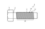
- FIG. 1 is a side view showing the configuration of the fastening member according to the first embodiment of the present invention.
- FIG. 2 is a flowchart illustrating a method of manufacturing a fastening member according to the first embodiment of the present invention.
- FIG. 3 is a plan view showing the configuration of the fastening member according to the second embodiment of the present invention.
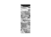
- FIG. 4 is a diagram showing a crystal grain map at a screw valley of the fastening member according to the first embodiment of the present invention.
- FIG. 5 is a diagram showing a crystal grain map at a screw valley of the fastening member according to the second embodiment of the present invention.
- FIG. 6 is a diagram showing a crystal grain map at a screw valley of the fastening member according to the third embodiment of the present invention.
- FIG. 1 is a side view showing the configuration of the fastening member according to the first embodiment of the present invention.
- FIG. 2 is a flowchart illustrating a method of manufacturing a fastening member according to the
- FIG. 7 is a diagram showing a crystal grain map at a screw valley of the fastening member according to the fourth embodiment of the present invention.
- FIG. 8 is a diagram showing a crystal grain map at a screw valley of the fastening member according to Comparative Example 1 of the present invention.
- FIG. 9 is a diagram showing a crystal grain map at a screw valley of the fastening member according to Comparative Example 2 of the present invention.
- FIG. 10 is a diagram showing a crystal grain map at a screw valley of the fastening member according to Comparative Example 3 of the present invention.
- FIG. 11 is a diagram showing a crystal grain map at a screw valley of the fastening member according to Comparative Example 4 of the present invention.
- FIG. 12 is a diagram showing a crystal orientation difference map at a screw valley of the fastening member according to the first embodiment of the present invention.
- FIG. 13 is a diagram showing a crystal orientation difference map at a screw valley of the fastening member according to the second embodiment of the present invention.
- FIG. 14 is a diagram showing a crystal orientation difference map at a screw valley of the fastening member according to Comparative Example 1 of the present invention.
- FIG. 15 is a diagram showing a crystal orientation difference map at a screw valley of a fastening member according to Comparative Example 2 of the present invention.
- FIG. 16 is a diagram for explaining the measurement timing of the axial force in the relaxation resistance test.
- FIG. 1 is a side view showing the configuration of the fastening member according to the first embodiment of the present invention.
- the fastening member 1 shown in FIG. 1 is a bolt (a type of male screw) made of an aluminum (Al) alloy.
- the fastening member 1 has a cylindrical shaft portion 2, a head portion 3 provided at one end of the shaft portion 2 in the axial direction (left-right direction in FIG. 1), and a neck portion forming a boundary between the shaft portion 2 and the head portion 3. 4 and.
- the shaft portion 2 has a screw portion 22 having a thread 21 formed on its surface.
- the shape of the head 3 (hexagonal trim type) is merely an example, and other shapes (hexagonal flange type, pan type, dish type, truss type, flat type, etc.) may be provided.
- a screw valley 23 is formed between the threads 21 adjacent to each other in the axial direction of the shaft portion 2.
- the head 3 is not always necessary, and an implant bolt having no head (for example, JIS standard: JIS B 1173) may be used.
- the fastening member 1 is made of an aluminum alloy containing silicon (Si), copper (Cu), manganese (Mn), magnesium (Mg) and zinc (Zn), and the balance is aluminum (Al) and unavoidable impurities.
- the aluminum alloy according to the present embodiment is an alloy having an equivalent composition of an aluminum alloy having an alloy number of A6056 or an alloy having an increased amount of Cu in the equivalent composition of the aluminum alloy of A6056.
- the aluminum alloy contains Si of 0.6% or more and 1.4% or less, Cu of 0.5% or more and 5.0% or less, and Mn of 0.3% or more and 1.1% or less in terms of mass ratio. It contains Mg of 0.5% or more and 1.3% or less and Zn of 0.01% or more and 0.8% or less.
- the aluminum alloy may contain a combination of zirconium (Zr) and titanium (Ti) in an amount of 0.2% or less.
- the Cu content (standard value) of the A6056 aluminum alloy is 0.5% or more and 1.1% or less.
- the content indicates the content ratio in the mass ratio. In the following description, the content indicates the content ratio in the mass ratio.
- Mg 2 Si is precipitated by the aging treatment of Si, and the strength can be increased by the precipitation of Mg 2 Si.
- the Si content exceeds 1.4%, the elongation of the alloy is lowered. Further, if the Si content is less than 0.6, the strength improving effect of the Mg 2 Si precipitate is insufficient.
- CuAl 2 and Al 2 CuMg are precipitated by the aging treatment, and the strength can be increased by these precipitates.
- the Cu content is 1.5% or more and 4.0% or less, the amount of these precipitates can be further increased, and the strength can be further improved.
- the Cu content exceeds 5.0%, the corrosion resistance, stress corrosion cracking resistance, and elongation of the alloy are lowered. Further, if the Cu content is less than 0.5%, the strength improving effect of these precipitates is insufficient.
- Mn is an element that exhibits solid solution strengthening.
- Al—Mn—Si-based precipitates can also be produced by the aging treatment to increase the strength.
- the Mn content exceeds 1.1%, the elongation of the alloy will be reduced. Further, if the Mn content is less than 0.3%, the strength improving effect of these precipitates is insufficient.
- the strength of Mg can be increased by precipitating Mg 2 Si by aging treatment.
- the Mg content exceeds 1.3%, the elongation is lowered. Further, if the Mg content is less than 0.5%, the strength improving effect of the Mg 2 Si precipitate is insufficient.
- MgZn 2 is precipitated by the aging treatment to increase the strength.
- the Zn content exceeds 0.8%, the corrosion resistance, stress corrosion cracking resistance, and elongation of the alloy are lowered. Further, if the Zn content is less than 0.01%, the strength improving effect of these precipitates is insufficient.
- the fastening member 1 has a circle-equivalent average crystal grain size of 4 ⁇ m or more and 50 ⁇ m or less in a region from the surface of the screw valley 23 to a depth of 200 ⁇ m.
- the depth from the screw valley 23 is the distance from the surface of the screw valley 23, which is the distance toward the central axis of the shaft portion 2 and in the direction orthogonal to the central axis.
- the average crystal grain size equivalent to a circle here is the diameter of the circle. If the average crystal grain size equivalent to a circle is less than 4 ⁇ m, intergranular slip is likely to occur, which is considered to reduce relaxation resistance. On the other hand, when the average crystal grain size equivalent to a circle exceeds 50 ⁇ m, the ductility is lowered and the possibility of cracking in the heading treatment or the rolling treatment is increased.
- the fastening member 1 has a KAM (Kernel Average Misorientation) value of 1.5 degrees or less, which indicates an average crystal orientation difference in a region from the surface of the screw valley 23 to a depth of 200 ⁇ m.
- KAM Kernel Average Misorientation
- the fastening member 1 has a tensile strength of 400 MPa or more. If the tensile strength is less than 400 MPa, the fastening member is enlarged in order to maintain the load capacity at the time of fastening (decrease in axial force), and thus the weight reduction is impaired.
- the fastening member 1 has a 0.2% proof stress of 370 MPa or more, which is a stress that makes the permanent strain remaining after unloading 0.2%. If the 0.2% proof stress is less than 370 MPa, the load at the time of fastening the elastic region is small, and when compensating for this, the fastening member is enlarged, so that the weight reduction is impaired.
- the ratio of the proportional limit to the tensile strength is 0.6 or more, preferably 0.7 or more.
- the proportional limit is the maximum stress for which Hooke's law holds in the stress-strain curve.
- the fastening member 1 is formed by processing a rod-shaped member made of the above-mentioned aluminum alloy.
- FIG. 2 is a flowchart illustrating a method of manufacturing a fastening member according to the first embodiment of the present invention.
- the rod-shaped member described above is forged (step S101).
- a rod-shaped member is sandwiched between dies and pressed.
- crushing for example, one end of a rod-shaped member is crushed to produce a first molded product having a shaft portion 2, a head portion 3 and a neck portion 4 excluding the screw portion 22.
- the first molded product formed by rolling is rolled (step S102).
- the first molded product is sandwiched and pressed by a mold having irregularities corresponding to the threads, and while the first molded product is rotated, one mold is applied to the other mold. By moving it, a thread 21 is formed on the shaft portion 2.
- the threaded portion 22 is formed on the shaft portion 2.
- the second molded product on which the threaded portion 22 is formed is heat-treated (step S103).
- the second molded product is treated at a high temperature to be solutioned (solutionized), and then aged.
- the set temperature in the solution treatment is preferably set to 500 ° C. to 570 ° C.
- the set temperature in the aging treatment is preferably set to 140 ° C. to 200 ° C.
- the fastening member 1 By manufacturing the fastening member 1 according to the above-mentioned flow, the fastening member 1 having the above characteristics can be obtained. Conventionally, it is common to perform the heat treatment in step S103 before the rolling process in step S102.
- FIG. 3 is a plan view showing the configuration of the fastening member according to the second embodiment of the present invention.
- the fastening member 5 shown in FIG. 3 is a nut (a type of female screw) made of the above-mentioned aluminum alloy.
- the fastening member 5 has a hollow columnar shape, and a screw thread 52 is formed on the inner surface of the hole 51 formed in the central portion.
- the shape of the fastening member 5 (hexagon nut) shown in FIG. 3 is merely an example, and can be realized as a nut having another shape (flange nut, bag nut, high nut, etc.).
- the fastening member 5 is formed by using the above-mentioned aluminum alloy and has a ring shape.
- the fastening member 5 is manufactured in the same manner as in the first embodiment for the rod-shaped member made of the aluminum alloy described above. For example, after rolling the screw thread 52, heat treatment is performed.
- the fastening member according to the present invention can be realized as a machine screw or a tapping screw which is a male screw other than a bolt.
- Example 1 A bolt (corresponding to the fastening member 1) was produced by using a rod-shaped member of A6056 aluminum alloy and heat-treating after the rolling process according to the flowchart shown in FIG.
- the bolts produced in this embodiment have a screw nominal value of M8 and a pitch of 1.25.
- KAM value average crystal grain size and the average crystal orientation difference
- EBSD electron backscatter diffraction
- a tensile test was performed on the bolt to determine the tensile strength, 0.2% proof stress, and proportional limit / tensile strength.
- the average crystal grain size and the average crystal orientation difference are values in the region from the bolt surface to depths of 100, 200, and 400 ⁇ m. The results are shown in Table 1.
- Example 2 Bolts were produced by processing according to the flowchart shown in FIG. 2 using a rod-shaped member having a Cu content ratio of 2.04% in the composition of the A6056 aluminum alloy. For a part of this bolt, the average crystal grain size and the average crystal orientation difference (KAM value) were obtained for each depth of the screw valley by the EBSD method. In addition, a tensile test was performed on the bolt to determine the tensile strength, 0.2% proof stress, and proportional limit / tensile strength. The results are shown in Table 1.
- Example 3 In the composition of A6056 aluminum alloy, Si content ratio is 0.92%, Fe content ratio is 0.24, Cu content ratio is 2.90%, Mn content ratio is 0.65%, Mg content ratio.
- a bolt was produced by processing according to the flowchart shown in FIG. 2 using a rod-shaped member having a content ratio of 0.89% and Zr + Ti of 0.17%. For a part of this bolt, the average crystal grain size and the average crystal orientation difference (KAM value) were obtained for each depth of the screw valley by the EBSD method. In addition, a tensile test was performed on the bolt to determine the tensile strength, 0.2% proof stress, and proportional limit / tensile strength. The results are shown in Table 1.
- Example 4 In the composition of A6056 aluminum alloy, Si content ratio is 0.92%, Cu content ratio is 3.94%, Mn content ratio is 0.69%, Mg content ratio is 0.88% and Zr + Ti content.
- Bolts were produced by processing according to the flowchart shown in FIG. 2 using a rod-shaped member having a ratio of 0.17%. For a part of this bolt, the average crystal grain size and the average crystal orientation difference (KAM value) were obtained for each depth of the screw valley by the EBSD method. In addition, a tensile test was performed on the bolt to determine the tensile strength, 0.2% proof stress, and proportional limit / tensile strength. The results are shown in Table 1.
- FIG. 4 is a diagram showing a crystal grain map at a screw valley of the fastening member according to the first embodiment of the present invention.
- FIG. 5 is a diagram showing a crystal grain map at a screw valley of the fastening member according to the second embodiment of the present invention.
- FIG. 6 is a diagram showing a crystal grain map at a screw valley of the fastening member according to the third embodiment of the present invention.
- FIG. 7 is a diagram showing a crystal grain map at a screw valley of the fastening member according to the fourth embodiment of the present invention.
- FIG. 8 is a diagram showing a crystal grain map at a screw valley of the fastening member according to Comparative Example 1 of the present invention.
- FIG. 9 is a diagram showing a crystal grain map at a screw valley of the fastening member according to Comparative Example 2 of the present invention.
- FIG. 10 is a diagram showing a crystal grain map at a screw valley of the fastening member according to Comparative Example 3 of the present invention.
- FIG. 11 is a diagram showing a crystal grain map at a screw valley of the fastening member according to Comparative Example 4 of the present invention.
- FIGS. 4 to 11 correspond to a part of a cross section including the deepest part of the screw valley (corresponding to the screw valley 23) of the manufactured bolt.
- the boundary line (black line) shown in the figure indicates a crystal grain boundary having an orientation difference of 5 ° or more, and the grains surrounded by this boundary line are regarded as one crystal grain.
- the average crystal grain size is the distance from the deepest portion of the thread valley (for example, the position P 0 shown in FIG. 4), and is the shaft portion of the bolt (on the shaft portion 2).
- the average particle size in each region toward the central axis of (corresponding to) and in the direction orthogonal to the central axis is 100 ⁇ m, 200 ⁇ m, and 400 ⁇ m from the surface, respectively, was calculated. As can be seen from the results shown in Table 1 and FIGS.
- Example 1 the average crystal grain size of the bolts (Examples 1 to 4) produced by heat treatment in the rolling process was rolled in the heat treatment. It is larger than the average crystal grain size of the bolts (Comparative Examples 1 to 4) produced by the treatment. Further, when Example 1 and Examples 2 to 4 are compared, it can be seen that the composition having a large amount of Cu has a larger average crystal grain size.
- FIG. 12 is a diagram showing a crystal orientation difference map at a screw valley of the fastening member according to the first embodiment of the present invention.
- FIG. 13 is a diagram showing a crystal orientation difference map at a screw valley of the fastening member according to the second embodiment of the present invention.
- FIG. 14 is a diagram showing a crystal orientation difference map at a screw valley of the fastening member according to Comparative Example 1 of the present invention.
- FIG. 15 is a diagram showing a crystal orientation difference map at a screw valley of a fastening member according to Comparative Example 2 of the present invention. 12 to 15 show a part of a cross section including the deepest part of the screw valley (corresponding to the screw valley 23) of the manufactured bolt.
- the average crystal orientation difference (KAM value) is the average of the orientation differences between all the measurement points adjacent to the measurement points with a diameter of about 0.7 ⁇ m in each region from the surface to the depths of 100 ⁇ m, 200 ⁇ m, and 400 ⁇ m. Each was calculated. As can be seen from the results shown in Table 1 and FIGS. 12 to 15, the average crystal orientation difference of the bolts (Examples 1 and 2) produced by heat treatment in the rolling process at each depth is the rolling in the heat treatment. It is smaller than the average crystal orientation difference of the bolts (Comparative Examples 1 and 2) produced by the treatment.
- the tensile strength and 0.2% proof stress shown in Table 1 show the average value of the values obtained by measuring 10 times. The minimum and maximum values are shown in parentheses at the bottom.
- the proportional limit is the stress (load) when the relationship between the load and the stroke deviates from the straight line. If the proportional limit / tensile strength is 0.6 or more, the load at the time of fastening in the elastic region can be relatively large, and the fastening member can be miniaturized. As a result, the weight of the fastening member can be reduced. Can be promoted.
- FIG. 16 is a diagram for explaining the measurement timing of the axial force in the relaxation resistance test.
- the time change of the axial force is shown by the solid line F 1
- the time change of the temperature is shown by the broken line T 1 .
- the temperature t 0 is room temperature.
- the axial force before heating (point Q 1 ) and the axial force after heating (point Q 2 ) were compared.
- the axial force before heating was 12.5 kN, which corresponds to the plastic region fastening of the A6056 aluminum alloy under the present fastening conditions.
- the axial forces of the bolts according to Examples 1 and 2 after heating were 9.0 kN and 9.8 kN, whereas the axial forces of the bolts according to Comparative Examples 1 and 2 after heating were 8.2 kN and 8.8 kN. It became. From this result, it can be seen that the relaxation resistance is excellent when the heat treatment is performed after rolling as in Examples 1 and 2.
- the present invention may include various embodiments not described here, and various design changes and the like may be made within a range that does not deviate from the technical idea specified by the claims. Is possible.
- the fastening member according to the present invention is suitable for obtaining a fastening member having excellent relaxation resistance.
Landscapes
- Chemical & Material Sciences (AREA)
- Engineering & Computer Science (AREA)
- Materials Engineering (AREA)
- Mechanical Engineering (AREA)
- Metallurgy (AREA)
- Organic Chemistry (AREA)
- Forging (AREA)
Priority Applications (1)
| Application Number | Priority Date | Filing Date | Title |
|---|---|---|---|
| JP2021574633A JP7650827B2 (ja) | 2020-01-31 | 2021-01-15 | 締結部材 |
Applications Claiming Priority (2)
| Application Number | Priority Date | Filing Date | Title |
|---|---|---|---|
| JP2020-015851 | 2020-01-31 | ||
| JP2020015851 | 2020-01-31 |
Publications (1)
| Publication Number | Publication Date |
|---|---|
| WO2021153286A1 true WO2021153286A1 (ja) | 2021-08-05 |
Family
ID=77079330
Family Applications (1)
| Application Number | Title | Priority Date | Filing Date |
|---|---|---|---|
| PCT/JP2021/001361 Ceased WO2021153286A1 (ja) | 2020-01-31 | 2021-01-15 | 締結部材 |
Country Status (2)
| Country | Link |
|---|---|
| JP (1) | JP7650827B2 (https=) |
| WO (1) | WO2021153286A1 (https=) |
Citations (5)
| Publication number | Priority date | Publication date | Assignee | Title |
|---|---|---|---|---|
| JP2010189750A (ja) * | 2009-02-20 | 2010-09-02 | Kobe Steel Ltd | 耐軟化性に優れた高強度アルミニウム合金線棒材およびその製造方法 |
| JP2011001602A (ja) * | 2009-06-18 | 2011-01-06 | Kobe Steel Ltd | 成形性に優れた高強度ボルト用アルミニウム合金線棒材およびその製造方法、高強度フランジボルトおよびその製造方法 |
| WO2013073575A1 (ja) * | 2011-11-16 | 2013-05-23 | 住友電気工業株式会社 | ボルト用アルミニウム合金線及びボルト並びにそれらの製造方法 |
| CN104451478A (zh) * | 2014-11-28 | 2015-03-25 | 中国科学院金属研究所 | 一种铝螺栓用高性能细晶铝合金线材、棒材的制备工艺 |
| WO2017142030A1 (ja) * | 2016-02-19 | 2017-08-24 | 日本発條株式会社 | アルミニウム合金および締結部材 |
-
2021
- 2021-01-15 JP JP2021574633A patent/JP7650827B2/ja active Active
- 2021-01-15 WO PCT/JP2021/001361 patent/WO2021153286A1/ja not_active Ceased
Patent Citations (5)
| Publication number | Priority date | Publication date | Assignee | Title |
|---|---|---|---|---|
| JP2010189750A (ja) * | 2009-02-20 | 2010-09-02 | Kobe Steel Ltd | 耐軟化性に優れた高強度アルミニウム合金線棒材およびその製造方法 |
| JP2011001602A (ja) * | 2009-06-18 | 2011-01-06 | Kobe Steel Ltd | 成形性に優れた高強度ボルト用アルミニウム合金線棒材およびその製造方法、高強度フランジボルトおよびその製造方法 |
| WO2013073575A1 (ja) * | 2011-11-16 | 2013-05-23 | 住友電気工業株式会社 | ボルト用アルミニウム合金線及びボルト並びにそれらの製造方法 |
| CN104451478A (zh) * | 2014-11-28 | 2015-03-25 | 中国科学院金属研究所 | 一种铝螺栓用高性能细晶铝合金线材、棒材的制备工艺 |
| WO2017142030A1 (ja) * | 2016-02-19 | 2017-08-24 | 日本発條株式会社 | アルミニウム合金および締結部材 |
Also Published As
| Publication number | Publication date |
|---|---|
| JP7650827B2 (ja) | 2025-03-25 |
| JPWO2021153286A1 (https=) | 2021-08-05 |
Similar Documents
| Publication | Publication Date | Title |
|---|---|---|
| EP2548983B1 (en) | High-strength bolt made from aluminium alloy | |
| JP6368087B2 (ja) | アルミニウム合金線材、アルミニウム合金線材の製造方法、及びアルミニウム合金部材 | |
| US5409555A (en) | Method of manufacturing a forged magnesium alloy | |
| CN103025901B (zh) | 具有分层的微结构的损伤容限性铝材料 | |
| JP5700650B2 (ja) | プレス成形性と強度のバランスに優れた純チタン板 | |
| CN103180473A (zh) | 由镁合金构成的线状体、螺栓、螺帽和垫圈 | |
| KR102943545B1 (ko) | 알루미늄 합금, 알루미늄 합금선, 알루미늄 합금 부재 및 볼트 | |
| TW201245592A (en) | Method for manufacture fastening component made from aluminum-based alloy, and fastening component made from aluminum-based alloy | |
| CN112853169A (zh) | 一种高强度的铝合金螺栓及其制造方法 | |
| JP6577652B2 (ja) | アルミニウム合金および締結部材 | |
| US20150165519A1 (en) | Shaped parts made from corrosion-resistant copper alloys | |
| JP7358759B2 (ja) | スクロール部材およびスクロール鍛造品の製造方法 | |
| JP5973975B2 (ja) | チタン板 | |
| EP3815809B1 (en) | Blind rivet nut and manufacturing method therefor | |
| JP5010309B2 (ja) | 高強度チタン合金製冷間鍛造用素材 | |
| WO2021153286A1 (ja) | 締結部材 | |
| JP2512235B2 (ja) | 銅合金 | |
| JP2013221161A (ja) | アルミニウム合金材 | |
| JP2022044919A (ja) | アルミニウム合金製鍛造部材及びその製造方法 | |
| JPH05271834A (ja) | 安定な人工時効性を有するアルミニウム合金 | |
| JP7496106B1 (ja) | アルミニウム合金製ねじ用素材及びアルミニウム合金製ねじ並びにその製造方法 | |
| JP2010174337A (ja) | 鍛造用Al−Mg−Si系合金ビレット | |
| US20260126075A1 (en) | Material for aluminum alloy screw, and aluminum alloy screw and production method therefor | |
| WO2010029572A1 (en) | Method for manufacture of aluminium alloy sheets | |
| RU2842750C1 (ru) | Ультрамелкозернистые алюминиевые сплавы с эффектом низкотемпературной сверхпластичности |
Legal Events
| Date | Code | Title | Description |
|---|---|---|---|
| 121 | Ep: the epo has been informed by wipo that ep was designated in this application |
Ref document number: 21747464 Country of ref document: EP Kind code of ref document: A1 |
|
| ENP | Entry into the national phase |
Ref document number: 2021574633 Country of ref document: JP Kind code of ref document: A |
|
| NENP | Non-entry into the national phase |
Ref country code: DE |
|
| 122 | Ep: pct application non-entry in european phase |
Ref document number: 21747464 Country of ref document: EP Kind code of ref document: A1 |