WO2021153037A1 - 熱延鋼板 - Google Patents
熱延鋼板 Download PDFInfo
- Publication number
- WO2021153037A1 WO2021153037A1 PCT/JP2020/046384 JP2020046384W WO2021153037A1 WO 2021153037 A1 WO2021153037 A1 WO 2021153037A1 JP 2020046384 W JP2020046384 W JP 2020046384W WO 2021153037 A1 WO2021153037 A1 WO 2021153037A1
- Authority
- WO
- WIPO (PCT)
- Prior art keywords
- less
- hot
- steel sheet
- rolled steel
- content
- Prior art date
Links
Images
Classifications
-
- C—CHEMISTRY; METALLURGY
- C22—METALLURGY; FERROUS OR NON-FERROUS ALLOYS; TREATMENT OF ALLOYS OR NON-FERROUS METALS
- C22C—ALLOYS
- C22C38/00—Ferrous alloys, e.g. steel alloys
- C22C38/001—Ferrous alloys, e.g. steel alloys containing N
-
- C—CHEMISTRY; METALLURGY
- C21—METALLURGY OF IRON
- C21D—MODIFYING THE PHYSICAL STRUCTURE OF FERROUS METALS; GENERAL DEVICES FOR HEAT TREATMENT OF FERROUS OR NON-FERROUS METALS OR ALLOYS; MAKING METAL MALLEABLE, e.g. BY DECARBURISATION OR TEMPERING
- C21D8/00—Modifying the physical properties by deformation combined with, or followed by, heat treatment
- C21D8/02—Modifying the physical properties by deformation combined with, or followed by, heat treatment during manufacturing of plates or strips
- C21D8/0221—Modifying the physical properties by deformation combined with, or followed by, heat treatment during manufacturing of plates or strips characterised by the working steps
- C21D8/0226—Hot rolling
-
- C—CHEMISTRY; METALLURGY
- C21—METALLURGY OF IRON
- C21D—MODIFYING THE PHYSICAL STRUCTURE OF FERROUS METALS; GENERAL DEVICES FOR HEAT TREATMENT OF FERROUS OR NON-FERROUS METALS OR ALLOYS; MAKING METAL MALLEABLE, e.g. BY DECARBURISATION OR TEMPERING
- C21D9/00—Heat treatment, e.g. annealing, hardening, quenching or tempering, adapted for particular articles; Furnaces therefor
- C21D9/46—Heat treatment, e.g. annealing, hardening, quenching or tempering, adapted for particular articles; Furnaces therefor for sheet metals
-
- C—CHEMISTRY; METALLURGY
- C22—METALLURGY; FERROUS OR NON-FERROUS ALLOYS; TREATMENT OF ALLOYS OR NON-FERROUS METALS
- C22C—ALLOYS
- C22C38/00—Ferrous alloys, e.g. steel alloys
- C22C38/002—Ferrous alloys, e.g. steel alloys containing In, Mg, or other elements not provided for in one single group C22C38/001 - C22C38/60
-
- C—CHEMISTRY; METALLURGY
- C22—METALLURGY; FERROUS OR NON-FERROUS ALLOYS; TREATMENT OF ALLOYS OR NON-FERROUS METALS
- C22C—ALLOYS
- C22C38/00—Ferrous alloys, e.g. steel alloys
- C22C38/02—Ferrous alloys, e.g. steel alloys containing silicon
-
- C—CHEMISTRY; METALLURGY
- C22—METALLURGY; FERROUS OR NON-FERROUS ALLOYS; TREATMENT OF ALLOYS OR NON-FERROUS METALS
- C22C—ALLOYS
- C22C38/00—Ferrous alloys, e.g. steel alloys
- C22C38/04—Ferrous alloys, e.g. steel alloys containing manganese
-
- C—CHEMISTRY; METALLURGY
- C22—METALLURGY; FERROUS OR NON-FERROUS ALLOYS; TREATMENT OF ALLOYS OR NON-FERROUS METALS
- C22C—ALLOYS
- C22C38/00—Ferrous alloys, e.g. steel alloys
- C22C38/06—Ferrous alloys, e.g. steel alloys containing aluminium
-
- C—CHEMISTRY; METALLURGY
- C22—METALLURGY; FERROUS OR NON-FERROUS ALLOYS; TREATMENT OF ALLOYS OR NON-FERROUS METALS
- C22C—ALLOYS
- C22C38/00—Ferrous alloys, e.g. steel alloys
- C22C38/12—Ferrous alloys, e.g. steel alloys containing tungsten, tantalum, molybdenum, vanadium, or niobium
-
- C—CHEMISTRY; METALLURGY
- C22—METALLURGY; FERROUS OR NON-FERROUS ALLOYS; TREATMENT OF ALLOYS OR NON-FERROUS METALS
- C22C—ALLOYS
- C22C38/00—Ferrous alloys, e.g. steel alloys
- C22C38/14—Ferrous alloys, e.g. steel alloys containing titanium or zirconium
-
- C—CHEMISTRY; METALLURGY
- C22—METALLURGY; FERROUS OR NON-FERROUS ALLOYS; TREATMENT OF ALLOYS OR NON-FERROUS METALS
- C22C—ALLOYS
- C22C38/00—Ferrous alloys, e.g. steel alloys
- C22C38/18—Ferrous alloys, e.g. steel alloys containing chromium
- C22C38/34—Ferrous alloys, e.g. steel alloys containing chromium with more than 1.5% by weight of silicon
-
- C—CHEMISTRY; METALLURGY
- C22—METALLURGY; FERROUS OR NON-FERROUS ALLOYS; TREATMENT OF ALLOYS OR NON-FERROUS METALS
- C22C—ALLOYS
- C22C38/00—Ferrous alloys, e.g. steel alloys
- C22C38/18—Ferrous alloys, e.g. steel alloys containing chromium
- C22C38/40—Ferrous alloys, e.g. steel alloys containing chromium with nickel
- C22C38/42—Ferrous alloys, e.g. steel alloys containing chromium with nickel with copper
-
- C—CHEMISTRY; METALLURGY
- C22—METALLURGY; FERROUS OR NON-FERROUS ALLOYS; TREATMENT OF ALLOYS OR NON-FERROUS METALS
- C22C—ALLOYS
- C22C38/00—Ferrous alloys, e.g. steel alloys
- C22C38/18—Ferrous alloys, e.g. steel alloys containing chromium
- C22C38/40—Ferrous alloys, e.g. steel alloys containing chromium with nickel
- C22C38/44—Ferrous alloys, e.g. steel alloys containing chromium with nickel with molybdenum or tungsten
-
- C—CHEMISTRY; METALLURGY
- C22—METALLURGY; FERROUS OR NON-FERROUS ALLOYS; TREATMENT OF ALLOYS OR NON-FERROUS METALS
- C22C—ALLOYS
- C22C38/00—Ferrous alloys, e.g. steel alloys
- C22C38/18—Ferrous alloys, e.g. steel alloys containing chromium
- C22C38/40—Ferrous alloys, e.g. steel alloys containing chromium with nickel
- C22C38/58—Ferrous alloys, e.g. steel alloys containing chromium with nickel with more than 1.5% by weight of manganese
-
- C—CHEMISTRY; METALLURGY
- C21—METALLURGY OF IRON
- C21D—MODIFYING THE PHYSICAL STRUCTURE OF FERROUS METALS; GENERAL DEVICES FOR HEAT TREATMENT OF FERROUS OR NON-FERROUS METALS OR ALLOYS; MAKING METAL MALLEABLE, e.g. BY DECARBURISATION OR TEMPERING
- C21D2211/00—Microstructure comprising significant phases
- C21D2211/001—Austenite
-
- C—CHEMISTRY; METALLURGY
- C21—METALLURGY OF IRON
- C21D—MODIFYING THE PHYSICAL STRUCTURE OF FERROUS METALS; GENERAL DEVICES FOR HEAT TREATMENT OF FERROUS OR NON-FERROUS METALS OR ALLOYS; MAKING METAL MALLEABLE, e.g. BY DECARBURISATION OR TEMPERING
- C21D2211/00—Microstructure comprising significant phases
- C21D2211/005—Ferrite
-
- C—CHEMISTRY; METALLURGY
- C21—METALLURGY OF IRON
- C21D—MODIFYING THE PHYSICAL STRUCTURE OF FERROUS METALS; GENERAL DEVICES FOR HEAT TREATMENT OF FERROUS OR NON-FERROUS METALS OR ALLOYS; MAKING METAL MALLEABLE, e.g. BY DECARBURISATION OR TEMPERING
- C21D2211/00—Microstructure comprising significant phases
- C21D2211/009—Pearlite
Definitions
- the present invention relates to a hot-rolled steel sheet. Specifically, the present invention relates to a hot-rolled steel sheet that is formed into various shapes by press working or the like and is used, and in particular, a hot-rolled steel sheet that has high strength and is excellent in ductility and shearing workability.
- the present application claims priority based on Japanese Patent Application No. 2020-010944 filed in Japan on January 27, 2020, the contents of which are incorporated herein by reference.
- Patent Document 1 states that retained austenite having an average crystal grain size of 5 ⁇ m or less is dispersed in ferrite having an average crystal grain size of 10 ⁇ m or less to improve collision resistance and moldability.
- Excellent automotive high-strength steel sheets are disclosed.
- austenite undergoes martensitic transformation during processing and exhibits a large elongation due to transformation-induced plasticity, but the formation of hard martensite impairs hole expansion.
- Patent Document 1 discloses that not only ductility but also hole expansion property is improved by miniaturizing ferrite and retained austenite.
- Patent Document 2 discloses a high-strength steel plate having excellent ductility and stretch flangeability and a tensile strength of 980 MPa or more, in which a second phase composed of retained austenite and / or martensite is finely dispersed in crystal grains. There is.
- Patent Document 4 discloses a technique for improving peeling and creases on the end face of a plate by reducing the content of P.
- Patent Documents 1 to 4 are all techniques for improving either ductility or end face properties after shearing. However, Patent Documents 1 to 3 do not mention a technique for achieving both of these characteristics. Patent Document 4 refers to both shearing workability and press moldability. However, since the strength of the steel sheet disclosed in Patent Document 4 is less than 850 MPa, it may be difficult to apply it to a member having a high strength of 980 MPa or more.
- the ratio of the sheared surface to the end face after the shearing process is not stable, and the accuracy of the cut end face varies.
- the present invention has been made in view of the above problems of the prior art, and an object of the present invention is to provide a hot-rolled steel sheet having high strength and excellent ductility and shearing workability.
- having excellent shearing workability means that the ratio of the sheared surface to the end face after shearing (hereinafter, may be referred to as the sheared surface ratio) is stable (the amount of change in the sheared surface ratio is small). ) Indicates that. Further, having excellent strength or high strength means that the tensile strength is 980 MPa or more.
- a hard structure is generally formed in a phase transformation of 600 ° C. or lower, but in this temperature range, a grain boundary having a crystal orientation difference of 60 ° with respect to the ⁇ 110> direction and a crystal orientation difference of 7 A large number of grain boundaries at ° are formed.
- the gist of the present invention made based on the above findings is as follows.
- the hot-rolled steel sheet according to one aspect of the present invention has a chemical composition of mass%.
- C 0.050 to 0.250%
- Si 0.05 to 3.00%
- Mn 1.00 to 4.00%
- One or more of Ti, Nb and V 0.060 to 0.500% in total, sol.
- Al 0.001 to 2.000%, P: 0.100% or less, S: 0.0300% or less, N: 0.1000% or less, O: 0.0100% or less, Cu: 0-2.00%, Cr: 0 to 2.00%, Mo: 0 to 1.00%, Ni: 0 to 2.00%, B: 0 to 0.0100%, Ca: 0-0.0200%, Mg: 0-0.0200%, REM: 0 to 0.1000%, Bi: 0 to 0.020%, One or more of Zr, Co, Zn and W: 0 to 1.00% in total, and Sn: 0 to 0.050%.
- the rest consists of Fe and impurities
- the metal structure is% of the area, Retained austenite is less than 3.0% Ferrite is 15.0% or more and less than 60.0%, Pearlite is less than 5.0% L 60 / L 7 which is the ratio of the grain boundary length L 60 having a crystal orientation difference of 60 ° and the grain boundary length L 7 having a crystal orientation difference of 7 ° about the ⁇ 110> direction. Is 0.60 or more, The standard deviation of the Mn concentration is 0.60% by mass or less, The tensile strength is 980 MPa or more.
- the hot-rolled steel sheet according to (1) above may have an average crystal grain size of less than 3.0 ⁇ m on the surface layer.
- the hot-rolled steel sheet according to (1) or (2) above has a chemical composition of% by mass.
- a hot-rolled steel sheet having excellent strength, ductility and shear workability can be obtained. Further, according to the above-mentioned preferred embodiment according to the present invention, it is possible to obtain a hot-rolled steel sheet having the above-mentioned characteristics and further suppressing the occurrence of bending internal cracks, that is, having excellent bending internal crack resistance. can.
- the hot-rolled steel sheet according to the above aspect of the present invention is suitable as an industrial material used for automobile members, mechanical structural members, and building members.
- the hot-rolled steel sheet according to the present embodiment has C: 0.050 to 0.250%, Si: 0.05 to 3.00%, Mn: 1.00 to 4.00%, Ti in mass%. , Nb and V, one or more: 0.060 to 0.500% in total, sol. Al: 0.001 to 2.000%, P: 0.100% or less, S: 0.0300% or less, N: 0.1000% or less, O: 0.0100% or less, and the balance: Fe and impurities including. Each element will be described in detail below.
- C 0.050 to 0.250% C increases the surface integral of the hard phase and increases the strength of ferrite by combining with precipitation strengthening elements such as Ti, Nb, and V. If the C content is less than 0.050%, it becomes difficult to obtain the desired strength. Therefore, the C content is set to 0.050% or more.
- the C content is preferably 0.060% or more, more preferably 0.070% or more.
- the C content is set to 0.250% or less.
- the C content is preferably 0.150% or less, less than 0.150%, and 0.130% or less.
- Si 0.05 to 3.00%
- Si has an action of promoting the formation of ferrite to improve the ductility of the hot-rolled steel sheet and an action of solid-solving and strengthening the ferrite to increase the strength of the hot-rolled steel sheet.
- Si has an action of making the steel sound by deoxidation (suppressing the occurrence of defects such as blow holes in the steel). If the Si content is less than 0.05%, the effect of the above action cannot be obtained. Therefore, the Si content is set to 0.05% or more.
- the Si content is preferably 0.30% or more, 0.50% or more, and 0.80% or more.
- the Si content is 3.00% greater than the surface texture and chemical conversion of the hot-rolled steel sheet, more with ductility and weldability is significantly degraded, A 3 transformation point increases significantly. This makes it difficult to perform hot rolling in a stable manner. Therefore, the Si content is set to 3.00% or less.
- the Si content is preferably 2.70% or less, more preferably 2.50% or less.
- Mn 1.00 to 4.00% Mn has the effect of suppressing the ferrite transformation and increasing the strength of the hot-rolled steel sheet. If the Mn content is less than 1.00%, a tensile strength of 980 MPa or more cannot be obtained. Therefore, the Mn content is set to 1.00% or more.
- the Mn content is preferably 1.50% or more, more preferably 1.80% or more.
- the Mn content exceeds 4.00%, the angular difference of the crystal grains in the hard phase becomes non-uniform due to the segregation of Mn, and the shear plane ratio becomes unstable. Therefore, the Mn content is set to 4.00% or less.
- the Mn content is preferably 3.70% or less and 3.50% or less.
- Ti, Nb and V 0.060 to 0.500% in total Ti, Nb and V are elements that are finely precipitated in steel as carbides and nitrides and improve the strength of steel by precipitation strengthening. Further, it is an element that fixes C by forming the above-mentioned carbide and suppresses the formation of cementite, which is harmful to shearing workability. In order to obtain these effects, the total content of Ti, Nb and V is set to 0.060% or more. It is not necessary that all of Ti, Nb and V are contained, and any one of them may be contained.
- Ti, Nb and V may contain one of Ti, Nb and V and its content may be 0.060% or more, and may contain two or more of Ti, Nb and V and the total content thereof is 0.060. It may be% or more.
- the total content of Ti, Nb and V is preferably 0.080% or more.
- the total content of Ti, Nb and V is set to 0.500% or less. It is preferably 0.300% or less, and more preferably 0.250% or less.
- sol. Al 0.001 to 2.000% Like Si, Al has the effect of deoxidizing the steel to make it sound, and also has the effect of promoting the formation of ferrite and increasing the ductility of the hot-rolled steel sheet. sol. If the Al content is less than 0.001%, the effect of the above action cannot be obtained. Therefore, sol. The Al content is 0.001% or more. sol. The Al content is preferably 0.010% or more and 0.030% or more. On the other hand, sol. If the Al content exceeds 2.000%, the above effects are saturated and economically unfavorable. The Al content is 2.000% or less. sol. The Al content is preferably 1.500% or less, 1.000% or less, 0.500% or less, and 0.100% or less. In this embodiment, sol. Al means acid-soluble Al, and indicates solid solution Al existing in steel in a solid solution state.
- P 0.100% or less
- P is an element generally contained as an impurity, but it is also an element having an effect of increasing the strength of a hot-rolled steel sheet by solid solution strengthening. Therefore, P may be positively contained, but P is an element that is easily segregated, and when the P content exceeds 0.100%, the decrease in ductility due to grain boundary segregation becomes remarkable. Therefore, the P content is set to 0.100% or less.
- the P content is preferably 0.030% or less.
- the lower limit of the P content does not need to be specified, but it is preferably 0.001% from the viewpoint of refining cost.
- S 0.0300% or less
- S is an element contained as an impurity and forms sulfide-based inclusions in the steel to reduce the ductility of the hot-rolled steel sheet.
- the S content exceeds 0.0300%, the ductility of the hot-rolled steel sheet is significantly reduced. Therefore, the S content is 0.0300% or less.
- the S content is preferably 0.0050% or less.
- the lower limit of the S content does not need to be specified, but is preferably 0.0001% from the viewpoint of refining cost.
- N 0.1000% or less
- N is an element contained in steel as an impurity and has an effect of reducing the ductility of the hot-rolled steel sheet. If the N content exceeds 0.1000%, the ductility of the hot-rolled steel sheet is significantly reduced. Therefore, the N content is set to 0.1000% or less.
- the N content is preferably 0.0800% or less, and more preferably 0.0700% or less.
- the lower limit of the N content does not need to be specified, but when one or more of Ti, Nb and V are contained to further refine the metal structure, the precipitation of carbonitride is promoted.
- the N content is preferably 0.0010% or more, and more preferably 0.0020% or more.
- O 0.0100% or less
- O forms a coarse oxide that becomes a starting point of fracture when it is contained in a large amount in steel, and causes brittle fracture and hydrogen-induced cracking. Therefore, the O content is set to 0.0100% or less.
- the O content is preferably 0.0080% or less and 0.0050% or less.
- the O content may be 0.0005% or more and 0.0010% or more in order to disperse a large number of fine oxides when the molten steel is deoxidized.
- the balance of the chemical composition of the hot-rolled steel sheet according to the present embodiment may be Fe and impurities.
- the impurities mean those mixed from ore as a raw material, scrap, manufacturing environment, etc., and are allowed as long as they do not adversely affect the hot-rolled steel sheet according to the present embodiment. do.
- the hot-rolled steel sheet according to the present embodiment contains Cu, Cr, Mo, Ni, B, Ca, Mg, REM, Bi, Zr, Co, Zn, W and Sn as optional elements instead of a part of Fe. You may. When the above optional element is not contained, the lower limit of the content is 0%. Hereinafter, the above optional elements will be described in detail.
- the Cu has an action of enhancing the hardenability of the hot-rolled steel sheet and an action of precipitating as carbide in the steel at a low temperature to increase the strength of the hot-rolled steel sheet.
- the Cu content is preferably 0.01% or more, and more preferably 0.05% or more.
- the Cu content is set to 2.00% or less.
- the Cu content is preferably 1.50% or less and 1.00% or less.
- the Cr content is preferably 0.01% or more and 0.05% or more.
- the Cr content is set to 2.00% or less.
- Mo has an action of enhancing the hardenability of the hot-rolled steel sheet and an action of precipitating as carbides in the steel to increase the strength of the hot-rolled steel sheet.
- the Mo content is preferably 0.01% or more and 0.02% or more.
- the Mo content is set to 1.00% or less.
- the Mo content is preferably 0.50% or less and 0.20% or less.
- Ni has an effect of enhancing the hardenability of the hot-rolled steel sheet. Further, when Ni contains Cu, it has an effect of effectively suppressing the grain boundary cracking of the slab caused by Cu. In order to obtain the effect of the above action more reliably, the Ni content is preferably 0.02% or more. Since Ni is an expensive element, it is economically unfavorable to contain it in a large amount. Therefore, the Ni content is set to 2.00% or less.
- B has an effect of enhancing the hardenability of the hot-rolled steel sheet.
- the B content is preferably 0.0001% or more and 0.0002% or more.
- the B content is set to 0.0100% or less.
- the B content is preferably 0.0050% or less.
- Ca, Mg and REM all have an effect of improving the formability of the hot-rolled steel sheet by adjusting the shape of the inclusions in the steel to a preferable shape.
- Bi has an effect of improving the formability of the hot-rolled steel sheet by refining the solidified structure. Therefore, one or more of these elements may be contained. In order to obtain the effect of the above action more reliably, it is preferable that any one or more of Ca, Mg, REM and Bi is 0.0005% or more.
- the Ca content or Mg content exceeds 0.0200%, or when the REM content exceeds 0.1000%, inclusions are excessively formed in the steel, which in turn reduces the ductility of the hot-rolled steel sheet. May cause you to. Further, even if the Bi content exceeds 0.020%, the effect of the above action is saturated, which is economically unfavorable. Therefore, the Ca content and Mg content are 0.0200% or less, the REM content is 0.1000% or less, and the Bi content is 0.020% or less.
- the Bi content is preferably 0.010% or less.
- REM refers to a total of 17 elements composed of Sc, Y and lanthanoid, and the content of REM refers to the total content of these elements.
- lanthanoids they are industrially added in the form of misch metal.
- the present inventors have confirmed that the effect of the hot-rolled steel sheet according to the present embodiment is not impaired even if a small amount of Sn is contained. However, if a large amount of Sn is contained, defects may occur during hot rolling, so the Sn content is set to 0.050% or less.
- the chemical composition of the hot-rolled steel sheet described above may be measured by a general analysis method.
- ICP-AES Inductively Coupled Plasma-Atomic Emission Spectrometry
- sol. Al may be measured by ICP-AES using a filtrate obtained by heat-decomposing the sample with an acid.
- C and S may be measured by using the combustion-infrared absorption method, and N may be measured by using the inert gas melting-thermal conductivity method.
- the metal structure of the hot-rolled steel sheet according to the present embodiment will be described.
- the metal structure is an area%
- the retained austenite is less than 3.0%
- the ferrite is 15.0% or more and less than 60.0%
- the pearlite is 5.0%.
- L which is less than the ratio of the grain boundary length L 60 having a crystal orientation difference of 60 ° and the grain boundary length L 7 having a crystal orientation difference of 7 ° with the ⁇ 110> direction as the axis.
- 60 / L 7 is 0.60 or more
- the standard deviation of Mn concentration is 0.60 mass% or less. Therefore, the hot-rolled steel sheet according to the present embodiment can obtain excellent strength, ductility, and shear workability.
- the cross section parallel to the rolling direction the structure fraction in the metal structure at a depth of 1/4 of the plate thickness from the surface and the center position in the plate width direction, and the standard deviation of L 60 / L 7 and Mn concentration.
- the reason for defining the metal structure at the depth of 1/4 of the plate thickness from the surface and the center position in the plate width direction of the cross section parallel to the rolling direction is that the metal structure at this position indicates a typical metal structure of the steel sheet. Is.
- the position of 1/4 depth from the surface to the plate thickness is a region from 1/8 depth from the surface to 3/8 depth from the surface to the plate thickness.
- Retained austenite is a tissue that exists as a face-centered cubic lattice even at room temperature. Residual austenite enhances the ductility of hot-rolled steel sheets due to transformation-induced plasticity (TRIP).
- TRIP transformation-induced plasticity
- retained austenite transforms into high-carbon martensite during shearing and has an effect of inhibiting stable crack generation, which causes the shear plane ratio to become unstable.
- the surface integral of retained austenite is 3.0% or more, the above-mentioned action becomes apparent and the shearing workability of the hot-rolled steel sheet deteriorates. Therefore, the surface integral of retained austenite is less than 3.0%.
- the surface integral of retained austenite is preferably less than 1.0%. Since the smaller the retained austenite, the more preferable it is, the surface integral of the retained austenite may be 0%.
- Methods for measuring the area fraction of retained austenite include X-ray diffraction, EBSP (electron backscatter diffraction image, Electron Backscattering Diffraction Pattern) analysis, and magnetic measurement methods, and the measured values may differ depending on the measurement method. ..
- the surface integral of retained austenite is measured by X-ray diffraction.
- the depth of 1/4 of the plate thickness of the hot-rolled steel plate (1/8 depth from the surface to the plate thickness to 3 / of the plate thickness from the surface).
- the integrated intensity of a total of 6 peaks of ⁇ (200) and ⁇ (220) is obtained and calculated by using the intensity averaging method to obtain the area fraction of retained austenite.
- Ferrite is a structure formed when fcc is transformed into bcc at a relatively high temperature. Since ferrite has a high work hardening rate, it has the effect of increasing the strength-ductility balance of hot-rolled steel sheets. In order to obtain the above action, the surface integral of ferrite is set to 15.0% or more. It is preferably 20.0% or more. On the other hand, since ferrite has low strength, it is not possible to obtain a desired tensile strength if the surface integral is excessive. Therefore, the surface integral of ferrite is set to less than 60.0%. It is preferably 50.0% or less, 45.0% or less, and 40.0% or less.
- Pearlite is a lamellar metal structure in which cementite is deposited in layers between ferrites, and is a soft metal structure compared to bainite and martensite. be.
- the surface integral of pearlite is set to less than 5.0%.
- the surface integral of pearlite is preferably 3.0% or less, 2.0% or less, and 1.0% or less. In order to improve the ductility of the hot-rolled steel sheet, the surface integral of pearlite is preferably reduced as much as possible, and the lower limit thereof is 0%.
- the hot-rolled steel sheet according to the present embodiment has a residual structure other than retained austenite, ferrite and pearlite.
- a hard structure consisting of one or more of bainite, martensite and tempered martensite having a total area fraction of more than 32.0% and 85.0% or less may be included.
- the total surface integral of bainite, martensite and tempered martensite is preferably more than 32.0%. More preferably, it is 35.0% or more, 40.0% or more, more than 43.0%, and 50.0% or more.
- the total surface integral of bainite, martensite and tempered martensite is preferably 85.0% or less. More preferably, it is 80.0% or less, 75.0% or less, and 70.0% or less.
- one of bainite, martensite and tempered martensite may be contained, and the area fraction thereof may be more than 32.0% and 85.0% or less, and among bainite, martensite and tempered martensite. Two or more types may be included, and the total area fraction thereof may be more than 32.0% and 85.0% or less.
- the surface integral of ferrite and pearlite is measured by the following method.
- the cross section perpendicular to the rolling direction is mirror-finished and polished at room temperature with colloidal silica containing no alkaline solution for 8 minutes to remove the strain introduced into the surface layer of the sample.
- the length is 50 ⁇ m and the thickness is from the surface so that it can be measured at a depth of 1/4 of the plate thickness from the surface and at the center position in the plate width direction.
- Crystal orientation information is obtained by measuring a region from 1/8 depth to 3/8 depth of the plate thickness at a measurement interval of 0.1 ⁇ m by the electron backscattering diffraction method.
- an EBSD analyzer composed of a thermal field emission scanning electron microscope (JSM-7001F manufactured by JEOL) and an EBSD detector (DVC5 type detector manufactured by TSL) is used.
- the degree of vacuum in the EBSD analyzer is 9.6 ⁇ 10-5 Pa or less
- the acceleration voltage is 15 kV
- the irradiation current level is 13
- the electron beam irradiation level is 62.
- the reflected electron image is taken in the same field of view.
- crystal grains in which ferrite and cementite are precipitated in layers are specified from the reflected electron image, and the area fraction of the crystal grains is calculated to obtain the area fraction of pearlite.
- the obtained crystal orientation information is applied to the "OIM Analysis (registered trademark)" (manufactured by AMETek) attached to the EBSD analyzer, and the "Grain Average” is installed.
- OIM Analysis registered trademark
- AMETek manufactured by AMETek
- the "Grain Average” is installed.
- a region having a Grain Ametek Measurement value of 1.0 ° or less is determined to be ferrite.
- the surface integral of ferrite is obtained by obtaining the surface integral of the region determined to be ferrite.
- the area fraction of the residual structure (hard structure consisting of one or more of bainite, martensite and tempered martensite) ranges from 100% to the area fraction of retained austenite, the area fraction of ferrite and the area fraction of pearlite. Obtained by subtracting the rate.
- L 60 / L 7 0.60 or more
- a hard structure is generally formed in a phase transformation of 600 ° C. or lower, but in this temperature range, the grain boundary with a crystal orientation difference of 60 ° and the crystal orientation difference of 7 ° with the ⁇ 110> direction as the axis. A large amount of grain boundaries are formed. Dislocations are less likely to accumulate in the hard structure during the formation of grain boundaries with a crystal orientation difference of 60 ° about the ⁇ 110> direction.
- the density of such grain boundaries is high and the grain boundaries are uniformly dispersed (that is, the total length of the grain boundaries having a crystal orientation difference of 60 ° with respect to the ⁇ 110> direction is calculated.
- strain is hard to concentrate inside the hard structure, and cracks are stably generated regardless of the presence or absence of the hard phase near the cutting edge of the shear tool. As a result, the shear plane ratio becomes stable.
- dislocations are likely to accumulate in the hard phase at grain boundaries where the crystal orientation difference is 7 ° with respect to the ⁇ 110> direction. Therefore, in a metal structure having a high grain boundary density with a crystal orientation difference of 7 ° about the ⁇ 110> direction in the hard phase, the hard phase is easily deformed, so that dislocations are introduced into the hard phase during shearing. Since crack generation is promoted from the inside of the hard phase, the shear surface ratio changes depending on the presence or absence of the hard phase near the cutting edge of the shear tool. As a result, the shear plane ratio becomes unstable.
- L 60 when the length of the grain boundary having a crystal orientation difference of 60 ° is L 60 and the length of the grain boundary having a crystal orientation difference of 7 ° is L 7 with the ⁇ 110> direction as the axis, the shear plane.
- the stability of the ratio is dominated by L 60 / L 7.
- L 60 / L 7 is less than 0.60, the shear plane ratio becomes unstable due to the above action. Therefore, in order to improve the shearing workability of the hot-rolled steel sheet, it is necessary to set L 60 / L 7 to 0.60 or more.
- L 60 / L 7 is preferably 0.63 or more, 0.65 or more, and 0.70 or more.
- the upper limit of L 60 / L 7 is not particularly specified, but may be 1.50 or less and 1.00 or less.
- the grain boundary having a crystal orientation difference of X ° about the ⁇ 110> direction means that when two adjacent crystal grains A and B are specified at a certain grain boundary, one crystal grain B is defined as ⁇ . 110> refers to a grain boundary having a crystal boundary in which the crystal orientations of the crystal grains A and the crystal grains B are the same when rotated by X ° along the axis. However, considering the measurement accuracy of the crystal orientation, an orientation difference of ⁇ 4 ° is allowed from the matching orientation relation.
- a highly inclined sample is irradiated with an electron beam in a scanning electron microscope (SEM), the Kikuchi pattern formed by backscattering is photographed with a high-sensitivity camera, and the photographed photograph is image-processed by a computer. By doing so, the crystal orientation of the irradiation point can be measured in a short waiting time.
- SEM scanning electron microscope
- the EBSP-OIM method is performed using an EBSD analyzer composed of a thermal field emission scanning electron microscope (JSM-7001F manufactured by JEOL) and an EBSD detector, and an OIM Analysis (registered trademark) manufactured by AMETEK.
- JSM-7001F thermal field emission scanning electron microscope
- EBSD detector an OIM Analysis (registered trademark) manufactured by AMETEK.
- OIM Analysis registered trademark manufactured by AMETEK.
- the analyzable area of the EBSP-OIM method is an area that can be observed by SEM. Although it depends on the resolution of the SEM, according to the EBSP-OIM method, analysis can be performed with a minimum resolution of 20 nm.
- Ferrite and pearlite are soft phases and have little effect on the dislocation accumulation effect inside the hard phase, and retained austenite is not a structure formed by phase transformation at 600 ° C or lower and has no dislocation accumulation effect. Therefore, in this measurement method, ferrite, pearlite and retained austenite are not included in the analysis. That is, in this embodiment, as an axis of ⁇ 110> direction, the grain boundary length L 7 length L 60, and the crystal orientation difference of grain boundary misorientation is 60 ° is 7 °, the hard It is of a tissue (one or more of bainite, martensite and tempered martensite).
- Pearlite can be specified by the same method as the method for measuring the area fraction of pearlite
- ferrite can be specified by the same method as the method for measuring the area fraction of ferrite
- pearlite and ferrite can be excluded from the analysis target.
- retained austenite having a crystal structure of fcc can be excluded from the analysis target.
- Standard deviation of Mn concentration 0.60% by mass or less 1/4 depth from the surface of the hot-rolled steel sheet according to the present embodiment (1/8 depth from the surface to the surface)
- the standard deviation of the Mn concentration at the center position in the plate width direction is 0.60 mass% or less.
- the standard deviation of the Mn concentration is preferably 0.55% by mass or less, 0.50% by mass or less, and 0.45% by mass or less.
- the lower limit of the standard deviation of the Mn concentration is preferably as small as the value from the viewpoint of stabilizing the shear surface ratio, but the practical lower limit is 0.10% by mass due to the restrictions of the manufacturing process.
- the standard deviation of the Mn concentration is measured by the following method. After mirror-polishing the L cross section of the hot-rolled steel sheet, the depth from the surface to 1/4 of the plate thickness (the region from the surface to the depth of 1/8 of the plate thickness to the region from the surface to the depth of 3/8 of the plate thickness) and the plate width. The center position in the direction is measured with an electron probe microanalyzer (EPMA) to measure the standard deviation of the Mn concentration.
- the measurement conditions are that the acceleration voltage is 15 kV, the magnification is 5000 times, and the distribution image in the range of 20 ⁇ m in the sample rolling direction and 20 ⁇ m in the sample plate thickness direction is measured. More specifically, the measurement interval is set to 0.1 ⁇ m, and the Mn concentration at 40,000 or more points is measured.
- the standard deviation of the Mn concentration is obtained by calculating the standard deviation based on the Mn concentration obtained from all the measurement points.
- the mechanism of internal bending cracking is presumed as follows. During bending, compressive stress is generated inside the bend. At first, the entire inside of the bend is deformed uniformly while processing proceeds, but when the amount of processing increases, the deformation cannot be carried out only by uniform deformation, and the deformation progresses due to the local concentration of strain (generation of shear deformation zone). .. As this shear band grows further, cracks along the shear band are generated from the inner surface of the bend and grow.
- in-bending cracks are more likely to occur as the strength increases is that uniform deformation is less likely to proceed due to the decrease in work hardening ability due to the increase in strength, and biased deformation is likely to occur at an early stage of processing ( It is presumed that a shear band is generated (or under loose processing conditions).
- the internal bending crack becomes remarkable in the steel sheet having a tensile strength of 980 MPa or more. Further, the present inventors have found that the finer the crystal grain size of the surface layer of the hot-rolled steel sheet, the more the local strain concentration is suppressed and the less likely it is that internal bending cracks occur.
- the average crystal grain size of the surface layer of the hot-rolled steel sheet is preferably less than 3.0 ⁇ m. More preferably, it is 2.5 ⁇ m or less. The lower limit is not particularly limited, but may be 1.0 ⁇ m or more, 1.5 ⁇ m or more, or 2.0 ⁇ m or more.
- the surface layer is a region from the surface of the hot-rolled steel sheet to a depth of 50 ⁇ m from the surface.
- the crystal grain size of the surface layer is measured using the above-mentioned EBSP-OIM method.
- analysis was performed in a region of 1200 times magnification and 40 ⁇ m ⁇ 30 ⁇ m in at least 5 visual fields.
- a place where the angle difference between adjacent measurement points is 5 ° or more is defined as a grain boundary, and the crystal grain size of the area average is calculated.
- the obtained area average crystal grain size is defined as the average crystal grain size of the surface layer.
- Retained austenite is not a structure generated by phase transformation at 600 ° C or lower and has no effect of dislocation accumulation. Therefore, retained austenite is not included in the analysis in this measurement method. That is, in the present embodiment, the average crystal grain size of the surface layer is that of ferrite, pearlite and a hard structure (one or more of bainite, martensite and tempered martensite). In the EBSP-OIM method, retained austenite having a crystal structure of fcc can be excluded from the analysis target.
- tensile strength characteristics are evaluated in accordance with JIS Z 2241: 2011.
- the test piece shall be JIS Z 2241: 2011 No. 5 test piece.
- the sampling position of the tensile test piece may be 1/4 from the end in the plate width direction, and the direction perpendicular to the rolling direction may be the longitudinal direction.
- the hot-rolled steel sheet according to this embodiment has a tensile (maximum) strength of 980 MPa or more. If the tensile strength is less than 980 MPa, the applicable parts are limited, and the contribution of weight reduction of the vehicle body is small.
- the upper limit is not particularly limited, but may be 1400 MPa or 1350 MPa from the viewpoint of suppressing mold wear.
- the product (TS ⁇ El) of the tensile strength which is an index of ductility, and the total elongation is preferably 15000 MPa ⁇ % or more.
- the plate thickness of the hot-rolled steel sheet according to the present embodiment is not particularly limited, but may be 0.5 to 8.0 mm.
- the thickness of the hot-rolled steel sheet according to the present embodiment may be 0.5 mm or more. It is preferably 1.2 mm or more and 1.4 mm or more.
- the plate thickness may be 8.0 mm or less. It is preferably 6.0 mm or less.
- the hot-rolled steel sheet according to the present embodiment having the above-mentioned chemical composition and metal structure may be provided with a plating layer on the surface for the purpose of improving corrosion resistance or the like to be a surface-treated steel sheet.
- the plating layer may be an electroplating layer or a hot-dip plating layer.
- the electroplating layer include electrogalvanization and electroZn—Ni alloy plating.
- the hot-dip plating layer include hot-dip zinc plating, alloyed hot-dip zinc plating, hot-dip aluminum plating, hot-dip Zn-Al alloy plating, hot-dip Zn-Al-Mg alloy plating, and hot-dip Zn-Al-Mg-Si alloy plating.
- NS hot-dip zinc plating, alloyed hot-dip zinc plating, hot-dip aluminum plating, hot-dip Zn-Al alloy plating, hot-dip Zn-Al-Mg alloy plating, and hot-dip Zn-Al-Mg-Si alloy plat
- the amount of plating adhesion is not particularly limited and may be the same as before. Further, it is also possible to further enhance the corrosion resistance by subjecting an appropriate chemical conversion treatment (for example, application and drying of a silicate-based chromium-free chemical conversion treatment liquid) after plating.
- an appropriate chemical conversion treatment for example, application and drying of a silicate-based chromium-free chemical conversion treatment liquid
- the slab is heated under predetermined conditions, then hot-rolled, accelerated and cooled to a predetermined temperature range, then slowly cooled, and cooled until winding. It is effective to control the history.
- the following steps (1) to (7) are sequentially performed.
- the temperature of the slab and the temperature of the steel plate in this embodiment refer to the surface temperature of the slab and the surface temperature of the steel plate.
- the slab is held in a temperature range of 700 to 850 ° C. for 900 seconds or longer, then further heated and held in a temperature range of 1100 ° C. or higher for 6000 seconds or longer.
- Hot rolling is performed in a temperature range of 850 to 1100 ° C. so that the total plate thickness is reduced by 90% or more.
- Hot rolling is completed so that the hot rolling completion temperature Tf becomes equal to or higher than the temperature T1 (° C.) represented by the following formula ⁇ 1>.
- the hot rolling is cooled to a temperature range of Tf-50 ° C or lower, and then accelerated to a temperature range of 600 to 730 ° C at an average cooling rate of 50 ° C / s or higher. Cooling. However, it is a more preferable cooling condition to cool to a temperature range of the hot rolling completion temperature Tf-50 ° C. or lower within 1 second after the completion of hot rolling. (5) In the temperature range of 600 to 730 ° C., slow cooling with an average cooling rate of less than 5 ° C./s is performed for 2.0 seconds or more. (6) Cool to a temperature range of 600 ° C. or lower at an average cooling rate of 50 ° C./s or higher. (7) Wind up in a temperature range of 400 to 600 ° C.
- T1 (° C.) 868-396 x [C] -68.1 x [Mn] + 24.6 x [Si] -36.1 x [Ni] -24.8 x [Cr] -20.7 x [Cu] ] + 250 ⁇ [sol. Al] ... ⁇ 1>
- the [element symbol] in the above formula ⁇ 1> indicates the content (mass%) of each element in the steel. If the element is not contained, 0 is substituted.
- the slab to be subjected to hot rolling is held in a temperature range of 700 to 850 ° C. during heating for 900 seconds or longer, and then further heated and held in a temperature range of 1100 ° C. or higher for 6000 seconds or longer.
- the temperature of the steel sheet may be changed in this temperature range or may be constant.
- the temperature of the steel sheet may be changed at 1100 ° C. or higher, or may be constant.
- Mn is dispersed between the ferrite and the austenite, and by lengthening the transformation time, Mn can be diffused in the ferrite region.
- the Mn microsegregation unevenly distributed in the slab can be eliminated, and the standard deviation of the Mn concentration can be significantly reduced.
- Hot rolling reduction rate A total plate thickness reduction of 90% or more in the temperature range of 850 to 1100 ° C. A total plate thickness reduction of 90% or more in the temperature range of 850 to 1100 ° C.
- the recrystallized austenite grains are mainly made finer, and the accumulation of strain energy in the unrecrystallized austenite grains is promoted.
- the recrystallization of austenite is promoted and the atomic diffusion of Mn is promoted, so that the standard deviation of the Mn concentration can be reduced.
- the standard deviation of the Mn concentration it is possible to uniformly disperse the grain boundaries having a crystal orientation difference of 60 ° about the ⁇ 110> direction in the final metal structure, and stabilize the shear plane ratio. can do. Therefore, it is preferable to perform hot rolling so that the total plate thickness is reduced by 90% or more in the temperature range of 850 to 1100 ° C.
- the plate thickness reduction in the temperature range of 850 to 1100 ° C. means that the inlet plate thickness before the first pass in rolling in this temperature range is t 0, and the outlet plate thickness after the final pass in rolling in this temperature range is t. When it is 1 , it can be expressed as (t 0 ⁇ t 1 ) / t 0 ⁇ 100 (%).
- Hot rolling completion temperature Tf T1 (° C.) or higher
- the hot rolling completion temperature Tf is preferably T1 (° C.) or higher.
- (6-4) Within 1 second after the completion of hot rolling, the temperature is cooled to a temperature range of Tf-50 ° C or lower, and then a temperature of 600 to 730 ° C at an average cooling rate of 50 ° C / s or higher. Accelerated cooling to a range Within 1 second after the completion of hot rolling, the temperature is cooled to a temperature range of Tf-50 ° C or lower, and then a temperature of 600 to 730 ° C at an average cooling rate of 50 ° C / s or higher. It is preferable to accelerate cooling to the region. However, it is a more preferable cooling condition to cool to a temperature range of the hot rolling completion temperature Tf-50 ° C. or lower within 1 second after the completion of hot rolling.
- the temperature is cooled to 50 ° C. or higher within 1 second after the completion of hot rolling, that is, within 1 second after the completion of hot rolling. It is more preferable to cool to a temperature range of Tf-50 ° C. or lower.
- Tf-50 ° C. or lower In order to cool to a temperature range of hot rolling completion temperature Tf-50 ° C or lower within 1 second after the completion of hot rolling, cooling with a large average cooling rate is performed immediately after the completion of hot rolling, for example, cooling water is applied to the surface of the steel sheet. It may be sprayed on.
- the average cooling rate here refers to the range of temperature drop of the steel plate from the start of accelerated cooling (when the steel plate is introduced into the cooling equipment) to the completion of accelerated cooling (when the steel plate is taken out from the cooling equipment). The value divided by the time required from the start to the completion of accelerated cooling.
- the upper limit of the average cooling rate is not specified, but if the cooling rate is increased, the cooling equipment becomes large and the equipment cost increases. Therefore, considering the equipment cost, 300 ° C./s or less is preferable.
- the average cooling rate here is the temperature drop width of the steel plate from the cooling stop temperature of accelerated cooling to the start temperature of slow cooling divided by the time required from the stop of accelerated cooling to the start of slow cooling. It refers to the value.
- the time for slow cooling in the temperature range of 600 to 730 ° C. is 2.0 seconds or more, the surface integral of the precipitation-strengthened ferrite reaches a desired amount, and the above action can be obtained. Therefore, in the temperature range of 600 to 730 ° C., slow cooling with an average cooling rate of less than 5 ° C./s is performed for 2.0 seconds or more.
- the time for slow cooling is preferably 3.0 seconds or longer, more preferably 4.0 seconds or longer.
- the upper limit of the time for slow cooling is determined by the equipment layout, but it may be less than 10.0 seconds. Further, although the lower limit of the average cooling rate for slow cooling is not particularly set, raising the temperature without cooling may require a large investment in equipment, and may be set to 0 ° C./s or higher.
- the average cooling rate up to is 50 ° C./s or more. As a result, the matrix structure can be made hard.
- the average cooling rate referred to here is the temperature drop width of the steel plate from the cooling stop temperature of slow cooling where the average cooling rate is less than 5 ° C / s to the winding temperature, and the average cooling rate is less than 5 ° C / s. It means the value divided by the time required from the stop of slow cooling to 600 ° C.
- the average cooling rate from the cooling shutdown temperature of slow cooling where the average cooling rate is less than 5 ° C./s to the temperature range of 600 ° C. or lower is set to 50 ° C./s or more.
- Winding temperature 400-600 ° C
- the winding temperature is in the temperature range of 400 to 600 ° C.
- the transformation driving force from austenite to bcc can be reduced, and the deformation strength of austenite can be reduced. Therefore, when the bainite and martensite transformation from austenite, ⁇ 110> direction grain boundary length L 7 crystal orientation difference of 7 ° is reduced as the shaft, and ⁇ 110> crystal orientation difference direction axis
- L 60 / L 7 can be set to 0.60 or more. As a result, the shear plane ratio can be stabilized.
- the winding temperature is preferably in the temperature range of 400 to 600 ° C.
- the winding temperature is more preferably 450 ° C. or higher.
- the winding temperature is more preferably 550 ° C. or lower.
- the conditions in the examples are one condition example adopted for confirming the feasibility and effect of the present invention.
- the present invention is not limited to this one-condition example.
- the present invention can adopt various conditions as long as the gist of the present invention is not deviated and the object of the present invention is achieved.
- the test piece was JIS Z 2241: 2011 No. 5 test piece.
- the sampling position of the tensile test piece was 1/4 from the end in the plate width direction, and the direction perpendicular to the rolling direction was the longitudinal direction.
- Shear workability The shear workability of the hot-rolled steel sheet was evaluated by determining the amount of change in the shear surface ratio by a punching test. Five punched holes were prepared at the center of the plate width at a hole diameter of 10 mm, a clearance of 15%, and a punching speed of 3 m / s. Next, with respect to the five punched holes, the state of the end faces parallel to the rolling direction at ten places (two end faces per one punched hole) was photographed with an optical microscope view.
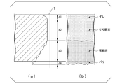
- FIG. 1A is a schematic view of an end face parallel to the rolling direction of the punched hole
- FIG. 1B is a schematic view of a side surface of the punched hole.
- the sagging is an R-shaped smooth surface
- the shearing surface is a punched end face separated by shear deformation
- the fracture surface is a punched end face separated by cracks generated from the vicinity of the cutting edge after the completion of shear deformation.
- a burr is a surface having protrusions protruding from the lower surface of a hot-rolled steel sheet.
- the ratio of the sheared surface to the end face is measured, and the difference between the maximum value and the minimum value of the obtained sheared surface ratio (%) is the sheared surface ratio.
- the ratio of the shear plane to the end face is such that a straight line 1 perpendicular to the upper surface and the lower surface of the hot-rolled steel plate is drawn in the observation photograph of the end face, and the sagging in the straight line 1 is drawn.
- the amount of change in the shear surface ratio was 20% or less, it was judged to be a hot-rolled steel sheet with excellent shearing workability and passed. On the other hand, if the amount of change in the shear surface ratio is more than 20%, it is judged that the hot-rolled steel sheet is inferior in shearing workability and is rejected.
- the presence or absence of cracks is determined by mirror-polishing the cross section of the test piece after the V block 90 ° bending test cut on a surface parallel to the bending direction and perpendicular to the plate surface, and then observing the cracks with an optical microscope. When the crack length observed inside the bend exceeds 30 ⁇ m, it is judged that there is a crack.
- the manufacturing No. which is a comparative example. 3 to 5, 7 to 12 and 26 to 30 were inferior in any one or more of strength, ductility and shearability.
- the present invention it is possible to provide a hot-rolled steel sheet having excellent strength, ductility and shear workability. Further, according to the above-mentioned preferred embodiment according to the present invention, it is possible to obtain a hot-rolled steel sheet having the above-mentioned characteristics and further suppressing the occurrence of bending internal cracks, that is, having excellent bending internal crack resistance. can.
- the hot-rolled steel sheet according to the present invention is suitable as an industrial material used for automobile members, mechanical structural members, and building members.
Abstract
Description
本願は、2020年1月27日に、日本に出願された特願2020-010944号に基づき優先権を主張し、その内容をここに援用する。
また、優れた強度または高い強度を有するとは、引張強さが980MPa以上であることを示す。
C:0.050~0.250%、
Si:0.05~3.00%、
Mn:1.00~4.00%、
Ti、NbおよびVのうち1種または2種以上:合計で0.060~0.500%、
sol.Al:0.001~2.000%、
P:0.100%以下、
S:0.0300%以下、
N:0.1000%以下、
O:0.0100%以下、
Cu:0~2.00%、
Cr:0~2.00%、
Mo:0~1.00%、
Ni:0~2.00%、
B:0~0.0100%、
Ca:0~0.0200%、
Mg:0~0.0200%、
REM:0~0.1000%、
Bi:0~0.020%、
Zr、Co、ZnおよびWのうち1種または2種以上:合計で0~1.00%、並びに
Sn:0~0.050%を含有し、
残部がFeおよび不純物からなり、
金属組織が、面積%で、
残留オーステナイトが3.0%未満であり、
フェライトが15.0%以上60.0%未満であり、
パーライトが5.0%未満であり、
<110>方向を軸として、結晶方位差が60°である粒界の長さL60と、結晶方位差が7°である粒界の長さL7との比であるL60/L7が0.60以上であり、
Mn濃度の標準偏差が0.60質量%以下であり、
引張強さが980MPa以上である。
(2)上記(1)に記載の熱延鋼板は、表層の平均結晶粒径が3.0μm未満であってもよい。
(3)上記(1)または(2)に記載の熱延鋼板は、前記化学組成が、質量%で、
Cu:0.01~2.00%、
Cr:0.01~2.00%、
Mo:0.01~1.00%、
Ni:0.02~2.00%、
B:0.0001~0.0100%、
Ca:0.0005~0.0200%、
Mg:0.0005~0.0200%、
REM:0.0005~0.1000%、および
Bi:0.0005~0.020%
からなる群から選択される1種または2種以上を含有してもよい。
以下の説明において、熱延鋼板の化学組成に関する%は特に指定しない限り質量%である。
本実施形態に係る熱延鋼板は、質量%で、C:0.050~0.250%、Si:0.05~3.00%、Mn:1.00~4.00%、Ti、NbおよびVのうち1種または2種以上:合計で0.060~0.500%、sol.Al:0.001~2.000%、P:0.100%以下、S:0.0300%以下、N:0.1000%以下、O:0.0100%以下、並びに、残部:Feおよび不純物を含む。以下に各元素について詳細に説明する。
Cは、硬質相の面積分率を上昇させるとともに、Ti、Nb、V等の析出強化元素と結合することで、フェライトの強度を上昇させる。C含有量が0.050%未満では、所望の強度を得ることが困難となる。したがって、C含有量は0.050%以上とする。C含有量は、好ましくは0.060%以上、より好ましくは0.070%以上である。
一方、C含有量が0.250%超では、フェライトの面積分率が低下することで、熱延鋼板の延性が低下する。したがって、C含有量は0.250%以下とする。C含有量は好ましくは0.150%以下、0.150%未満、0.130%以下である。
Siは、フェライトの生成を促進して熱延鋼板の延性を向上させる作用と、フェライトを固溶強化して熱延鋼板の強度を上昇させる作用とを有する。また、Siは脱酸により鋼を健全化する(鋼にブローホールなどの欠陥が生じることを抑制する)作用を有する。Si含有量が0.05%未満では、上記作用による効果を得ることができない。したがって、Si含有量は0.05%以上とする。Si含有量は、好ましくは0.30%以上、0.50%以上、0.80%以上である。
しかし、Si含有量が3.00%超では、熱延鋼板の表面性状および化成処理性、さらには延性および溶接性が著しく劣化するとともに、A3変態点が著しく上昇する。これにより、安定して熱間圧延を行うことが困難になる。したがって、Si含有量は3.00%以下とする。Si含有量は、好ましくは2.70%以下、より好ましくは2.50%以下である。
Mnは、フェライト変態を抑制して熱延鋼板を高強度化する作用を有する。Mn含有量が1.00%未満では、980MPa以上の引張強さを得ることができない。したがって、Mn含有量は1.00%以上とする。Mn含有量は、好ましくは1.50%以上であり、より好ましくは1.80%以上である。
一方、Mn含有量が4.00%超では、Mnの偏析に起因して、硬質相中の結晶粒の角度差が不均一となり、せん断面比率が不安定になる。したがって、Mn含有量は4.00%以下とする。Mn含有量は、好ましくは3.70%以下、3.50%以下である。
Ti、NbおよびVは、炭化物および窒化物として鋼中に微細析出し、析出強化により鋼の強度を向上させる元素である。また、上記炭化物を形成することによってCを固定して、せん断加工性にとって有害なセメンタイトの生成を抑制する元素である。これらの効果を得るため、Ti、NbおよびVの含有量の合計を0.060%以上とする。なお、Ti、NbおよびVの全てが含有されている必要はなく、いずれか1種でも含まれていればよい。Ti、NbおよびVのうち1種を含み、その含有量が0.060%以上であってもよく、Ti、NbおよびVのうち2種以上を含み、それらの含有量の合計が0.060%以上であってもよい。Ti、NbおよびVの合計の含有量は、好ましくは、0.080%以上である。
一方、Ti、NbおよびVの含有量の合計が0.500%を超えると、加工性が劣化する。そのため、Ti、NbおよびVの含有量の合計を0.500%以下とする。好ましくは、0.300%以下であり、より好ましくは、0.250%以下である。
Alは、Siと同様に、脱酸により鋼を健全化する作用を有するとともに、フェライトの生成を促進し、熱延鋼板の延性を高める作用を有する。sol.Al含有量が0.001%未満では上記作用による効果を得ることができない。したがって、sol.Al含有量は、0.001%以上とする。sol.Al含有量は、好ましくは0.010%以上、0.030%以上である。
一方、sol.Al含有量が2.000%超では、上記効果が飽和するとともに経済的に好ましくないため、sol.Al含有量は2.000%以下とする。sol.Al含有量は、好ましくは1.500%以下、1.000%以下、0.500%以下、0.100%以下である。
なお、本実施形態においてsol.Alとは、酸可溶性Alを意味し、固溶状態で鋼中に存在する固溶Alのことを示す。
Pは、一般的に不純物として含有される元素であるが、固溶強化により熱延鋼板の強度を高める作用を有する元素でもある。したがって、Pを積極的に含有させてもよいが、Pは偏析し易い元素であり、P含有量が0.100%を超えると、粒界偏析に起因する延性の低下が顕著となる。したがって、P含有量は、0.100%以下とする。P含有量は、好ましくは0.030%以下である。
P含有量の下限は特に規定する必要はないが、精錬コストの観点から、0.001%とすることが好ましい。
Sは、不純物として含有される元素であり、鋼中に硫化物系介在物を形成して熱延鋼板の延性を低下させる。S含有量が0.0300%を超えると、熱延鋼板の延性が著しく低下する。したがって、S含有量は0.0300%以下とする。S含有量は、好ましくは0.0050%以下である。
S含有量の下限は特に規定する必要はないが、精錬コストの観点から、0.0001%とすることが好ましい。
Nは、不純物として鋼中に含有される元素であり、熱延鋼板の延性を低下させる作用を有する。N含有量が0.1000%超では、熱延鋼板の延性が著しく低下する。したがって、N含有量は0.1000%以下とする。N含有量は、好ましくは0.0800%以下であり、さらに好ましくは0.0700%以下である。
N含有量の下限は特に規定する必要はないが、Ti、NbおよびVの1種または2種以上を含有させて金属組織をより微細化する場合には、炭窒化物の析出を促進させるためにN含有量は0.0010%以上とすることが好ましく、0.0020%以上とすることがより好ましい。
Oは、鋼中に多く含まれると破壊の起点となる粗大な酸化物を形成し、脆性破壊や水素誘起割れを引き起こす。そのため、O含有量は0.0100%以下とする。O含有量は、0.0080%以下、0.0050%以下とすることが好ましい。
溶鋼の脱酸時に微細な酸化物を多数分散させるために、O含有量は0.0005%以上、0.0010%以上としてもよい。
Cu、Cr、Mo、NiおよびBは、いずれも、熱延鋼板の焼入性を高めて引張強さを上昇させる作用を有する。また、CuおよびMoは鋼中に炭化物として析出して熱延鋼板の強度を高める作用を有する。さらに、Niは、Cuを含有させる場合においては、Cuに起因するスラブの粒界割れを効果的に抑制する作用を有する。したがって、これらの元素の1種または2種以上を含有させてもよい。
しかし、Cu含有量が2.00%超では、スラブの粒界割れが生じる場合がある。したがって、Cu含有量は2.00%以下とする。Cu含有量は、好ましくは1.50%以下、1.00%以下である。
しかし、Cr含有量が2.00%超では、熱延鋼板の化成処理性が著しく低下する。したがって、Cr含有量は2.00%以下とする。
しかし、Mo含有量を1.00%超としても上記作用による効果は飽和して経済的に好ましくない。したがって、Mo含有量は1.00%以下とする。Mo含有量は、好ましくは0.50%以下、0.20%以下である。
Niは、高価な元素であるため、多量に含有させることは経済的に好ましくない。したがって、Ni含有量は2.00%以下とする。
しかし、B含有量が0.0100%超では、熱延鋼板の延性が著しく低下するため、B含有量は0.0100%以下とする。B含有量は、0.0050%以下とすることが好ましい。
Ca、MgおよびREMは、いずれも、鋼中の介在物の形状を好ましい形状に調整することにより、熱延鋼板の成形性を高める作用を有する。また、Biは、凝固組織を微細化することにより、熱延鋼板の成形性を高める作用を有する。したがって、これらの元素の1種または2種以上を含有させてもよい。上記作用による効果をより確実に得るためには、Ca、Mg、REMおよびBiのいずれか1種以上を0.0005%以上とすることが好ましい。
Zr、Co、ZnおよびWについて、本発明者らは、これらの元素を合計で1.00%以下含有させても、本実施形態に係る熱延鋼板の効果は損なわれないことを確認している。そのため、Zr、Co、ZnおよびWのうち1種または2種以上を合計で1.00%以下含有させてもよい。
次に、本実施形態に係る熱延鋼板の金属組織について説明する。
本実施形態に係る熱延鋼板では、金属組織が、面積%で、残留オーステナイトが3.0%未満であり、フェライトが15.0%以上60.0%未満であり、パーライトが5.0%未満であり、<110>方向を軸として、結晶方位差が60°である粒界の長さL60と、結晶方位差が7°である粒界の長さL7との比であるL60/L7が0.60以上であり、Mn濃度の標準偏差が0.60質量%以下である。そのため、本実施形態に係る熱延鋼板は、優れた強度、延性およびせん断加工性を得ることができる。
なお、表面から板厚の1/4深さの位置とは、表面から板厚の1/8深さ~表面から板厚の3/8深さの領域のことである。
残留オーステナイトは室温でも面心立方格子として存在する組織である。残留オーステナイトは、変態誘起塑性(TRIP)により熱延鋼板の延性を高める。一方、残留オーステナイトは、せん断加工中には高炭素のマルテンサイトに変態して、安定的なき裂発生を阻害する作用を有するため、せん断面比率が不安定化する原因となる。残留オーステナイトの面積分率が3.0%以上では、上記作用が顕在化し、熱延鋼板のせん断加工性が劣化する。したがって、残留オーステナイトの面積分率は3.0%未満とする。残留オーステナイトの面積分率は、好ましくは1.0%未満である。残留オーステナイトは少ない程好ましいため、残留オーステナイトの面積分率は0%であってもよい。
フェライトは比較的高温でfccがbccに変態したときに生成する組織である。フェライトは加工硬化率が高いため、熱延鋼板の強度-延性バランスを高める作用がある。上記の作用を得るため、フェライトの面積分率は15.0%以上とする。好ましくは20.0%以上である。一方、フェライトは強度が低いため、面積分率が過剰であると所望の引張強さを得ることができない。このため、フェライトの面積分率は60.0%未満とする。好ましくは50.0%以下、45.0%以下、40.0%以下である。
パーライトはフェライト同士の間にセメンタイトが層状に析出したラメラ状の金属組織であり、またベイナイトやマルテンサイトと比較すると軟質な金属組織である。パーライトの面積分率が5.0%以上であると、パーライトに含まれるセメンタイトに炭素が消費され、残部組織であるマルテンサイトやベイナイトの強度が低下し、980MPa以上の引張強さを得ることができない。したがって、パーライトの面積分率は5.0%未満とする。パーライトの面積分率は、好ましくは3.0%以下、2.0%以下、1.0%以下である。熱延鋼板の延性を向上させるために、パーライトの面積分率は可能な限り低減することが好ましく、その下限は0%とする。
本実施形態に係る熱延鋼板には、残留オーステナイト、フェライトおよびパーライト以外の残部組織として、面積分率の合計が32.0%超85.0%以下のベイナイト、マルテンサイトおよび焼き戻しマルテンサイトの1種または2種以上からなる硬質組織が含まれてもよい。ベイナイト、マルテンサイトおよび焼き戻しマルテンサイトの面積分率の合計を32.0%超とすることで、熱延鋼板の強度を向上することができる。そのため、ベイナイト、マルテンサイトおよび焼き戻しマルテンサイトの面積分率の合計は32.0%超とすることが好ましい。より好ましくは、35.0%以上、40.0%以上、43.0%超、50.0%以上である。
圧延方向に垂直な断面を鏡面に仕上げ、室温においてアルカリ性溶液を含まないコロイダルシリカを用いて8分間研磨し、サンプルの表層に導入されたひずみを除去する。サンプル断面の長手方向の任意の位置において、圧延方向に平行な断面で、表面から板厚の1/4深さ且つ板幅方向中央位置について測定できるように、長さ50μm、表面から板厚の1/8深さ~表面から板厚の3/8深さの領域を、0.1μmの測定間隔で電子後方散乱回折法により測定して結晶方位情報を得る。
980MPa以上の高強度を得るには、母相を硬質な組織にする必要がある。硬質な組織は一般的に600℃以下の相変態において形成されるが、この温度域においては<110>方向を軸として、結晶方位差が60°である粒界と結晶方位差が7°である粒界とが多量に形成される。<110>方向を軸として、結晶方位差が60°である粒界の生成時においては、硬質組織中に転位が蓄積されにくい。そのため、硬質相中において、このような粒界の密度が高く、且つ均一に分散している(すなわち、<110>方向を軸として結晶方位差が60°である粒界の長さの合計が大きい)金属組織では、硬質相が変形しにくいため硬質組織の内部にひずみ集中しにくく、せん断工具の刃先近傍の硬質相の存在有無にかかわらずき裂が安定的に発生する。その結果、せん断面比率が安定する。
本実施形態に係る熱延鋼板の表面から板厚の1/4深さ(表面から板厚の1/8深さ~表面から板厚の3/8深さの領域)且つ板幅方向中央位置におけるMn濃度の標準偏差は0.60質量%以下である。これにより、<110>方向を軸として結晶方位差が60°である粒界を均一に分散させることができる。その結果、せん断面比率を安定化することができる。Mn濃度の標準偏差は、好ましくは、0.55質量%以下、0.50質量%以下、0.45質量%以下である。
熱延鋼板のL断面を鏡面研磨した後に、表面から板厚の1/4深さ(表面から板厚の1/8深さ~表面から板厚の3/8深さの領域)且つ板幅方向中央位置を電子プローブマイクロアナライザ(EPMA)で測定して、Mn濃度の標準偏差を測定する。測定条件は加速電圧を15kVとし、倍率を5000倍として試料圧延方向に20μm及び試料板厚方向に20μmの範囲の分布像を測定する。より具体的には、測定間隔を0.1μmとし、40000か所以上のMn濃度を測定する。次いで、全測定点から得られたMn濃度に基づいて標準偏差を算出することで、Mn濃度の標準偏差を得る。
鋼板強度が高くなるほど、曲げ加工時に曲げ内側から亀裂が生じやすくなる(以下、曲げ内割れと呼称する)。表層の結晶粒径を細かくすることで、熱延鋼板の曲げ内割れを抑制することができる。
なお、本実施形態において表層とは、熱延鋼板の表面~表面から深さ50μm位置の領域である。
熱延鋼板の機械的性質のうち引張強度特性(引張強さ、全伸び)は、JIS Z 2241:2011に準拠して評価する。試験片はJIS Z 2241:2011の5号試験片とする。引張試験片の採取位置は、板幅方向の端部から1/4部分とし、圧延方向に直角な方向を長手方向とすればよい。
本実施形態に係る熱延鋼板の板厚は特に限定されないが、0.5~8.0mmとしてもよい。熱延鋼板の板厚を0.5mm以上とすることで、圧延完了温度の確保が容易になるとともに圧延荷重を低減でき、熱間圧延を容易に行うことができる。したがって、本実施形態に係る熱延鋼板の板厚は0.5mm以上としてもよい。好ましくは1.2mm以上、1.4mm以上である。また、板厚を8.0mm以下とすることで、金属組織の微細化が容易となり、上述した金属組織を容易に確保することができる。したがって、板厚は8.0mm以下としてもよい。好ましくは6.0mm以下である。
(5-1)めっき層
上述した化学組成および金属組織を有する本実施形態に係る熱延鋼板は、表面に耐食性の向上等を目的としてめっき層を備えさせて表面処理鋼板としてもよい。めっき層は電気めっき層であってもよく溶融めっき層であってもよい。電気めっき層としては、電気亜鉛めっき、電気Zn-Ni合金めっき等が例示される。溶融めっき層としては、溶融亜鉛めっき、合金化溶融亜鉛めっき、溶融アルミニウムめっき、溶融Zn-Al合金めっき、溶融Zn-Al-Mg合金めっき、溶融Zn-Al-Mg-Si合金めっき等が例示される。
上述した化学組成および金属組織を有する本実施形態に係る熱延鋼板の好適な製造方法は、以下の通りである。
(1)スラブを700~850℃の温度域で900秒以上保持し、その後更に加熱し、1100℃以上の温度域で6000秒以上保持する。
(2)850~1100℃の温度域で合計90%以上の板厚減となるような熱間圧延を行う。
(3)熱間圧延完了温度Tfが下記式<1>により表される温度T1(℃)以上となるように熱間圧延を完了する。
(4)熱間圧延完了後1秒以内に、熱間圧延完了温度Tf-50℃以下の温度域まで冷却した後、50℃/s以上の平均冷却速度で600~730℃の温度域まで加速冷却する。
ただし、熱間圧延完了後1秒以内に、熱間圧延完了温度Tf-50℃以下の温度域まで冷却することは、より好ましい冷却条件である。
(5)600~730℃の温度域で、平均冷却速度が5℃/s未満である緩冷却を2.0秒以上行う。
(6)50℃/s以上の平均冷却速度で600℃以下の温度域まで冷却する。
(7)400~600℃の温度域で巻き取る。
ただし、上記式<1>中の[元素記号]は各元素の鋼中の含有量(質量%)を示す。当該元素を含有しない場合は0を代入する。
熱間圧延に供するスラブは、連続鋳造により得られたスラブや鋳造・分塊により得られたスラブなどを用いることができ、必要によってはそれらに熱間加工または冷間加工を加えたものを用いることができる。
また、スラブ加熱時のオーステナイト粒を均一にするためには、1100℃以上の温度域で6000秒以上加熱することが好ましい。
850~1100℃の温度域で合計90%以上の板厚減となるような熱間圧延を行うことにより、主に再結晶オーステナイト粒の微細化が図られるとともに、未再結晶オーステナイト粒内へのひずみエネルギーの蓄積が促進される。また、オーステナイトの再結晶が促進されるとともにMnの原子拡散が促進され、Mn濃度の標準偏差を小さくすることができる。
熱間圧延完了温度TfはT1(℃)以上とすることが好ましい。熱間圧延完了温度TfをT1(℃)以上とすることで、オーステナイト中のフェライト核生成サイト数の過剰な増大を抑制することができ、最終組織(製造後の熱延鋼板の金属組織)におけるフェライトの生成を抑えられ、高強度の熱延鋼板を得ることができる。
熱間圧延完了後1秒以内に、熱間圧延完了温度Tf-50℃以下の温度域まで冷却し、その後は50℃/s以上の平均冷却速度で600~730℃の温度域まで加速冷却することが好ましい。ただし、熱間圧延完了後1秒以内に、熱間圧延完了温度Tf-50℃以下の温度域まで冷却することは、より好ましい冷却条件である。
600~730℃の温度域で、平均冷却速度が5℃/s未満である緩冷却を2.0秒以上行うことにより、析出強化したフェライトを十分に析出させることができる。これにより、熱延鋼板の強度と延性とを両立することができる。
パーライトの面積分率を抑え、980MPa以上の引張強さを得るために、緩冷却の冷却停止温度から600℃までの平均冷却速度を50℃/s以上とする。これにより母相組織を硬質にすることができる。
巻取り温度は400~600℃の温度域とする。巻取り温度を400℃以上とすることで、オーステナイトからbccへの変態駆動力を小さくすることができ、また、オーステナイトの変形強度を小さくすることができる。そのため、オーステナイトからベイナイトおよびマルテンサイト変態する際に、<110>方向を軸として結晶方位差が7°である粒界の長さL7が減少し、且つ<110>方向を軸として結晶方位差が60°である粒界の長さL60が増加することで、L60/L7を0.60以上とすることができる。結果として、せん断面比率を安定化することができる。
なお、スラブを700~850℃の温度域において表3に示す保持時間で保持し、その後更に加熱して、表3に示す加熱温度まで加熱して保持した。また、緩冷却の平均冷却速度は5℃/s未満とした。
(1)引張強度特性
得られた熱延鋼板の機械的性質のうち引張強度特性(引張強さTSおよび全伸びEL)は、JIS Z 2241:2011に準拠して評価した。試験片はJIS Z 2241:2011の5号試験片とした。引張試験片の採取位置は、板幅方向の端部から1/4部分とし、圧延方向に直角な方向を長手方向とした。
熱延鋼板のせん断加工性は、打ち抜き試験によりせん断面比率の変化量を求めることで評価した。板幅中央位置に、穴直径10mm、クリアランス15%、打ち抜き速度3m/sで5個の打ち抜き穴を作製した。次に、5個の打ち抜き穴について、10箇所の圧延方向に平行な端面(1個の打ち抜き穴につき2箇所の端面)の様子を光学顕微鏡観で撮影した。
曲げ試験片は、熱延鋼板の幅方向1/2位置から、100mm×30mmの短冊形状の試験片を切り出し、以下の曲げ試験により耐曲げ内割れ性を評価した。
曲げ稜線が圧延方向(L方向)に平行である曲げ(L軸曲げ)と、曲げ稜線が圧延方向に垂直な方向(C方向)に平行である曲げ(C軸曲げ)の両者について、JIS Z 2248:2014(Vブロック90°曲げ試験)に準拠して耐曲げ内割れ性を調査し、亀裂の発生しない最小曲げ半径を求め、L軸およびC軸の最小曲げ半径の平均値Rを板厚tで除した値を限界曲げR/tとして曲げ性の指標値とした。R/t≦2.5であった場合、耐曲げ内割れ性に優れた熱延鋼板であると判断した。


Claims (3)
- 化学組成が、質量%で、
C:0.050~0.250%、
Si:0.05~3.00%、
Mn:1.00~4.00%、
Ti、NbおよびVのうち1種または2種以上:合計で0.060~0.500%、
sol.Al:0.001~2.000%、
P:0.100%以下、
S:0.0300%以下、
N:0.1000%以下、
O:0.0100%以下、
Cu:0~2.00%、
Cr:0~2.00%、
Mo:0~1.00%、
Ni:0~2.00%、
B:0~0.0100%、
Ca:0~0.0200%、
Mg:0~0.0200%、
REM:0~0.1000%、
Bi:0~0.020%、
Zr、Co、ZnおよびWのうち1種または2種以上:合計で0~1.00%、並びに
Sn:0~0.050%を含有し、
残部がFeおよび不純物からなり、
金属組織が、面積%で、
残留オーステナイトが3.0%未満であり、
フェライトが15.0%以上60.0%未満であり、
パーライトが5.0%未満であり、
<110>方向を軸として、結晶方位差が60°である粒界の長さL60と、結晶方位差が7°である粒界の長さL7との比であるL60/L7が0.60以上であり、
Mn濃度の標準偏差が0.60質量%以下であり、
引張強さが980MPa以上である
ことを特徴とする熱延鋼板。 - 表層の平均結晶粒径が3.0μm未満であることを特徴とする請求項1に記載の熱延鋼板。
- 前記化学組成が、質量%で、
Cu:0.01~2.00%、
Cr:0.01~2.00%、
Mo:0.01~1.00%、
Ni:0.02~2.00%、
B:0.0001~0.0100%、
Ca:0.0005~0.0200%、
Mg:0.0005~0.0200%、
REM:0.0005~0.1000%、および
Bi:0.0005~0.020%
からなる群から選択される1種または2種以上を含有する
ことを特徴とする請求項1または2に記載の熱延鋼板。
Priority Applications (6)
| Application Number | Priority Date | Filing Date | Title |
|---|---|---|---|
| CN202080093969.1A CN115003835B (zh) | 2020-01-27 | 2020-12-11 | 热轧钢板 |
| KR1020227025061A KR20220111724A (ko) | 2020-01-27 | 2020-12-11 | 열연 강판 |
| MX2022008861A MX2022008861A (es) | 2020-01-27 | 2020-12-11 | Lamina de acero laminada en caliente. |
| EP20916290.8A EP4098761A1 (en) | 2020-01-27 | 2020-12-11 | Hot-rolled steel sheet |
| US17/792,985 US20230055479A1 (en) | 2020-01-27 | 2020-12-11 | Hot-rolled steel sheet |
| JP2021574511A JP7260825B2 (ja) | 2020-01-27 | 2020-12-11 | 熱延鋼板 |
Applications Claiming Priority (2)
| Application Number | Priority Date | Filing Date | Title |
|---|---|---|---|
| JP2020-010944 | 2020-01-27 | ||
| JP2020010944 | 2020-01-27 |
Publications (1)
| Publication Number | Publication Date |
|---|---|
| WO2021153037A1 true WO2021153037A1 (ja) | 2021-08-05 |
Family
ID=77078504
Family Applications (1)
| Application Number | Title | Priority Date | Filing Date |
|---|---|---|---|
| PCT/JP2020/046384 WO2021153037A1 (ja) | 2020-01-27 | 2020-12-11 | 熱延鋼板 |
Country Status (7)
| Country | Link |
|---|---|
| US (1) | US20230055479A1 (ja) |
| EP (1) | EP4098761A1 (ja) |
| JP (1) | JP7260825B2 (ja) |
| KR (1) | KR20220111724A (ja) |
| CN (1) | CN115003835B (ja) |
| MX (1) | MX2022008861A (ja) |
| WO (1) | WO2021153037A1 (ja) |
Cited By (1)
| Publication number | Priority date | Publication date | Assignee | Title |
|---|---|---|---|---|
| WO2023170882A1 (ja) * | 2022-03-10 | 2023-09-14 | Jfeスチール株式会社 | 鋼板の製造方法、トリミング装置、製造装置、圧延鋼板、コイル材、及びブランク材 |
Citations (7)
| Publication number | Priority date | Publication date | Assignee | Title |
|---|---|---|---|---|
| JP2005179703A (ja) | 2003-12-16 | 2005-07-07 | Kobe Steel Ltd | 伸び、及び伸びフランジ性に優れた高強度鋼板 |
| JP2005298924A (ja) | 2004-04-13 | 2005-10-27 | Nippon Steel Corp | 打ち抜き加工性に優れた高強度熱延鋼板及びその製造方法 |
| JP2007070648A (ja) * | 2005-09-02 | 2007-03-22 | Nippon Steel Corp | 穴拡げ性に優れた高強度薄鋼板およびその製造方法 |
| JP2009263685A (ja) * | 2008-04-22 | 2009-11-12 | Nippon Steel Corp | 切断後の特性劣化の少ない高強度鋼板及びその製造方法 |
| WO2019009410A1 (ja) * | 2017-07-07 | 2019-01-10 | 新日鐵住金株式会社 | 熱延鋼板及びその製造方法 |
| JP2020010944A (ja) | 2018-07-20 | 2020-01-23 | 眞弓 仲山 | 折り畳み式トイレ |
| WO2020179292A1 (ja) * | 2019-03-06 | 2020-09-10 | 日本製鉄株式会社 | 熱延鋼板 |
Family Cites Families (4)
| Publication number | Priority date | Publication date | Assignee | Title |
|---|---|---|---|---|
| JPH1161326A (ja) | 1997-08-06 | 1999-03-05 | Nippon Steel Corp | 耐衝突安全性及び成形性に優れた自動車用高強度鋼板とその製造方法 |
| JP3355970B2 (ja) | 1996-12-10 | 2002-12-09 | 日本鋼管株式会社 | 打ち抜き性に優れる冷延鋼板の製造方法 |
| JP4299511B2 (ja) * | 2002-07-23 | 2009-07-22 | 新日本製鐵株式会社 | 打ち抜き性に優れた熱延鋼板 |
| JP6696209B2 (ja) * | 2016-02-18 | 2020-05-20 | 日本製鉄株式会社 | 高強度鋼板の製造方法 |
-
2020
- 2020-12-11 JP JP2021574511A patent/JP7260825B2/ja active Active
- 2020-12-11 KR KR1020227025061A patent/KR20220111724A/ko not_active Application Discontinuation
- 2020-12-11 CN CN202080093969.1A patent/CN115003835B/zh active Active
- 2020-12-11 US US17/792,985 patent/US20230055479A1/en active Pending
- 2020-12-11 EP EP20916290.8A patent/EP4098761A1/en active Pending
- 2020-12-11 MX MX2022008861A patent/MX2022008861A/es unknown
- 2020-12-11 WO PCT/JP2020/046384 patent/WO2021153037A1/ja unknown
Patent Citations (7)
| Publication number | Priority date | Publication date | Assignee | Title |
|---|---|---|---|---|
| JP2005179703A (ja) | 2003-12-16 | 2005-07-07 | Kobe Steel Ltd | 伸び、及び伸びフランジ性に優れた高強度鋼板 |
| JP2005298924A (ja) | 2004-04-13 | 2005-10-27 | Nippon Steel Corp | 打ち抜き加工性に優れた高強度熱延鋼板及びその製造方法 |
| JP2007070648A (ja) * | 2005-09-02 | 2007-03-22 | Nippon Steel Corp | 穴拡げ性に優れた高強度薄鋼板およびその製造方法 |
| JP2009263685A (ja) * | 2008-04-22 | 2009-11-12 | Nippon Steel Corp | 切断後の特性劣化の少ない高強度鋼板及びその製造方法 |
| WO2019009410A1 (ja) * | 2017-07-07 | 2019-01-10 | 新日鐵住金株式会社 | 熱延鋼板及びその製造方法 |
| JP2020010944A (ja) | 2018-07-20 | 2020-01-23 | 眞弓 仲山 | 折り畳み式トイレ |
| WO2020179292A1 (ja) * | 2019-03-06 | 2020-09-10 | 日本製鉄株式会社 | 熱延鋼板 |
Cited By (1)
| Publication number | Priority date | Publication date | Assignee | Title |
|---|---|---|---|---|
| WO2023170882A1 (ja) * | 2022-03-10 | 2023-09-14 | Jfeスチール株式会社 | 鋼板の製造方法、トリミング装置、製造装置、圧延鋼板、コイル材、及びブランク材 |
Also Published As
| Publication number | Publication date |
|---|---|
| MX2022008861A (es) | 2022-08-11 |
| JPWO2021153037A1 (ja) | 2021-08-05 |
| EP4098761A4 (en) | 2022-12-07 |
| US20230055479A1 (en) | 2023-02-23 |
| EP4098761A1 (en) | 2022-12-07 |
| JP7260825B2 (ja) | 2023-04-19 |
| KR20220111724A (ko) | 2022-08-09 |
| CN115003835B (zh) | 2024-04-12 |
| CN115003835A (zh) | 2022-09-02 |
Similar Documents
| Publication | Publication Date | Title |
|---|---|---|
| WO2021065346A1 (ja) | 熱延鋼板 | |
| CN113637923B (zh) | 钢板及镀覆钢板 | |
| JP6784344B1 (ja) | 熱延鋼板 | |
| JP6784343B1 (ja) | 熱延鋼板 | |
| WO2022044493A1 (ja) | 熱延鋼板 | |
| WO2023063010A1 (ja) | 熱間圧延鋼板 | |
| WO2021153037A1 (ja) | 熱延鋼板 | |
| WO2022044495A1 (ja) | 熱延鋼板 | |
| WO2021182395A1 (ja) | 熱延鋼板 | |
| WO2021182389A1 (ja) | 熱延鋼板 | |
| WO2021153036A1 (ja) | 熱延鋼板 | |
| WO2022044494A1 (ja) | 熱延鋼板 | |
| WO2022044492A1 (ja) | 熱延鋼板 | |
| KR20240051972A (ko) | 열간 압연 강판 | |
| KR20230167417A (ko) | 열연 강판 |
Legal Events
| Date | Code | Title | Description |
|---|---|---|---|
| 121 | Ep: the epo has been informed by wipo that ep was designated in this application |
Ref document number: 20916290 Country of ref document: EP Kind code of ref document: A1 |
|
| ENP | Entry into the national phase |
Ref document number: 2021574511 Country of ref document: JP Kind code of ref document: A |
|
| ENP | Entry into the national phase |
Ref document number: 20227025061 Country of ref document: KR Kind code of ref document: A |
|
| NENP | Non-entry into the national phase |
Ref country code: DE |
|
| ENP | Entry into the national phase |
Ref document number: 2020916290 Country of ref document: EP Effective date: 20220829 |