WO2021152968A1 - 光学系、画像投写装置および撮像装置 - Google Patents
光学系、画像投写装置および撮像装置 Download PDFInfo
- Publication number
- WO2021152968A1 WO2021152968A1 PCT/JP2020/042917 JP2020042917W WO2021152968A1 WO 2021152968 A1 WO2021152968 A1 WO 2021152968A1 JP 2020042917 W JP2020042917 W JP 2020042917W WO 2021152968 A1 WO2021152968 A1 WO 2021152968A1
- Authority
- WO
- WIPO (PCT)
- Prior art keywords
- lens
- optical system
- lens element
- magnifying
- focal length
- Prior art date
- Legal status (The legal status is an assumption and is not a legal conclusion. Google has not performed a legal analysis and makes no representation as to the accuracy of the status listed.)
- Ceased
Links
Images






Classifications
-
- G—PHYSICS
- G02—OPTICS
- G02B—OPTICAL ELEMENTS, SYSTEMS OR APPARATUS
- G02B13/00—Optical objectives specially designed for the purposes specified below
- G02B13/16—Optical objectives specially designed for the purposes specified below for use in conjunction with image converters or intensifiers, or for use with projectors, e.g. objectives for projection TV
-
- G—PHYSICS
- G02—OPTICS
- G02B—OPTICAL ELEMENTS, SYSTEMS OR APPARATUS
- G02B15/00—Optical objectives with means for varying the magnification
- G02B15/14—Optical objectives with means for varying the magnification by axial movement of one or more lenses or groups of lenses relative to the image plane for continuously varying the equivalent focal length of the objective
- G02B15/144—Optical objectives with means for varying the magnification by axial movement of one or more lenses or groups of lenses relative to the image plane for continuously varying the equivalent focal length of the objective having four groups only
- G02B15/1441—Optical objectives with means for varying the magnification by axial movement of one or more lenses or groups of lenses relative to the image plane for continuously varying the equivalent focal length of the objective having four groups only the first group being positive
- G02B15/144111—Optical objectives with means for varying the magnification by axial movement of one or more lenses or groups of lenses relative to the image plane for continuously varying the equivalent focal length of the objective having four groups only the first group being positive arranged ++-+
-
- G—PHYSICS
- G03—PHOTOGRAPHY; CINEMATOGRAPHY; ANALOGOUS TECHNIQUES USING WAVES OTHER THAN OPTICAL WAVES; ELECTROGRAPHY; HOLOGRAPHY
- G03B—APPARATUS OR ARRANGEMENTS FOR TAKING PHOTOGRAPHS OR FOR PROJECTING OR VIEWING THEM; APPARATUS OR ARRANGEMENTS EMPLOYING ANALOGOUS TECHNIQUES USING WAVES OTHER THAN OPTICAL WAVES; ACCESSORIES THEREFOR
- G03B21/00—Projectors or projection-type viewers; Accessories therefor
- G03B21/14—Details
- G03B21/16—Cooling; Preventing overheating
-
- G—PHYSICS
- G03—PHOTOGRAPHY; CINEMATOGRAPHY; ANALOGOUS TECHNIQUES USING WAVES OTHER THAN OPTICAL WAVES; ELECTROGRAPHY; HOLOGRAPHY
- G03B—APPARATUS OR ARRANGEMENTS FOR TAKING PHOTOGRAPHS OR FOR PROJECTING OR VIEWING THEM; APPARATUS OR ARRANGEMENTS EMPLOYING ANALOGOUS TECHNIQUES USING WAVES OTHER THAN OPTICAL WAVES; ACCESSORIES THEREFOR
- G03B5/00—Adjustment of optical system relative to image or object surface other than for focusing
-
- H—ELECTRICITY
- H04—ELECTRIC COMMUNICATION TECHNIQUE
- H04N—PICTORIAL COMMUNICATION, e.g. TELEVISION
- H04N5/00—Details of television systems
- H04N5/74—Projection arrangements for image reproduction, e.g. using eidophor
-
- H—ELECTRICITY
- H04—ELECTRIC COMMUNICATION TECHNIQUE
- H04N—PICTORIAL COMMUNICATION, e.g. TELEVISION
- H04N23/00—Cameras or camera modules comprising electronic image sensors; Control thereof
- H04N23/50—Constructional details
- H04N23/55—Optical parts specially adapted for electronic image sensors; Mounting thereof
Definitions
- the present disclosure relates to an optical system that forms an intermediate image.
- the present disclosure also relates to an image projection device and an image pickup device using such an optical system.
- the intermediate imaging type optical system has the advantage of being able to realize wide-angle projection of a large screen with a short focus, but the overall length of the optical system tends to be large. Therefore, the optical system becomes heavy, and when a part of the optical system is mounted outside the housing of the image projection device main body, the optical system is tilted with respect to the device main body due to the moment acting on the center of gravity, and the optical performance may deteriorate. There is sex.
- Synthetic resin has a lower specific gravity than glass, but has lower thermal conductivity and a higher coefficient of linear expansion. Therefore, although the weight of the optical system can be reduced, optical aberration, particularly chromatic aberration, tends to increase due to local temperature rise and thermal deformation. This tendency becomes particularly remarkable in the case of high-luminance projection.
- Patent Document 1 discloses a wide-angle imaging optical system, and the first lens L1a closest to the magnifying conjugate point has the largest aperture. Since the first lens L1a has aspherical surfaces on both sides and has a considerably complicated shape, it is presumed that a synthetic resin lens is used. However, it is expected that such a complicated aspherical shape becomes considerably sensitive to thermal deformation, and the deterioration of optical aberration due to temperature rise becomes remarkable.
- the present disclosure provides an optical system capable of reducing the moment acting on the center of gravity and reducing the influence of heat.
- the present disclosure also provides an image projection device and an image pickup device using such an optical system.
- One aspect of the present disclosure is an optical system having an intermediate imaging position internally which is conjugate to the enlargement conjugate point on the enlargement side and the reduction conjugate point on the reduction side, respectively.
- a magnifying optical system having a plurality of lens elements and located on the magnifying side of the intermediate imaging position, It has a plurality of lens elements, and includes a relay optical system located on the reduction side of the intermediate imaging position.
- the first lens element located on the magnifying side among the plurality of lens elements in the magnifying optical system is an aspherical lens having a negative power.
- ⁇ pgfn (ngn-nfn) / (nfn-ncn)-(-2.20599 ⁇ 10 -3 ⁇ vdn + 6.69612 ⁇ 10 -1 )
- vdn Abbe number of the first lens element
- ngn Refractive index of the first lens element with respect to g line
- nfn Refractive index of the first lens element with respect to
- ncn Refractive index of the first lens element with respect to C line
- fp Focal length of the magnifying optical system fr: Focal length of the relay optical system at the wide-angle end.
- the image projection device includes the above optical system and an image forming element that generates an image projected on a screen via the optical system.
- the image pickup apparatus includes the above optical system and an image pickup element that receives an optical image formed by the optical system and converts it into an electrical image signal.
- the moment acting on the center of gravity can be reduced, and the influence of heat can be reduced. Therefore, stable optical performance can be maintained when high-intensity light passes through the lens, for example, in the case of high-luminance projection.
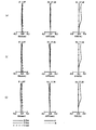
- FIG. 6 is a longitudinal aberration diagram at an object distance of 1066 mm of the zoom lens system of Example 1.
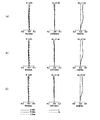
- FIG. 6 is a longitudinal aberration diagram at an object distance of 1066 mm of the zoom lens system of Example 2.
- FIG. 6 is a longitudinal aberration diagram at an object distance of 1066 mm of the zoom lens system of Example 3.
- FIG. 6 is a longitudinal aberration diagram at an object distance of 1066 mm of the zoom lens system of Example 4.
- FIG. 6 is a longitudinal aberration diagram at an object distance of 1066 mm of the zoom lens system of Example 5.
- FIG. 6 is a longitudinal aberration diagram at an object distance of 1066 mm of the zoom lens system of Example 6.
- FIG. 6 is a longitudinal aberration diagram of the zoom lens system of Example 7 at an object distance of 1066 mm.
- the optical system projects the image light of the original image S, in which the incident light is spatially modulated by an image forming element such as a liquid crystal display or a DMD (Digital Micromirror Device) based on the image signal, onto the screen (image projection).
- an image forming element such as a liquid crystal display or a DMD (Digital Micromirror Device)
- the optical system according to the present disclosure can be used for arranging a screen (not shown) on the extension line on the enlargement side and enlarging the original image S on the image forming element arranged on the reduction side and projecting it on the screen.
- the optical system according to the present disclosure is for collecting light emitted from an object located on an extension line on the enlargement side and forming an optical image of the object on the image pickup surface of an image pickup element arranged on the reduction side. Is also available.
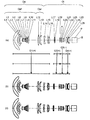
- FIGS. 1, 4, 7, 10, 13, 16 and 19 are layout drawings showing an optical path at a wide-angle end at an object distance of 1066 mm of the zoom lens system according to Examples 1 to 7.
- 2, 5, 8, 11, 14, 17, and 20 are layouts of wide-angle ends of the zoom lens system according to Examples 1 to 7 at an object distance of 1066 mm.
- 2 (a), 5 (a), 8 (a), 11 (a), 14 (a), 17 (a), and 20 (a) show a lens arrangement diagram at the wide-angle end of the zoom lens system.
- 2 (b), 5 (b), 8 (b), 11 (b), 14 (b), 17 (b), and 20 (b) show lens arrangement diagrams at intermediate positions of the zoom lens system.
- 2 (c), 5 (c), 8 (c), 11 (c), 14 (c), 17 (c), and 20 (c) show a lens arrangement diagram at the telephoto end of the zoom lens system.
- the wide-angle end is the shortest focal length state in which the entire system has the shortest focal length fw.
- the intermediate position is the intermediate focal length state between the wide-angle end and the telephoto end.
- the zoom lens system according to the first embodiment includes a first lens group G1 to a fourth lens group G4 and an optical element P.
- the first lens group G1 has a positive power, is composed of the first lens element L1 to the fifteenth lens element L15, and includes surfaces 1 to 30 (see numerical examples described later).
- the second lens group G2 has a positive power, is composed of the 16th lens element L16 to the 18th lens element L18, and includes the surfaces 31 to 36.
- the third lens group G3 has a negative power, is composed of the 19th lens element L19 to the 22nd lens element L22, and includes surfaces 37 to 45.
- the fourth lens group G4 has a positive power, is composed of the 23rd lens element L23 to the 25th lens element L25, and includes surfaces 46 to 51.
- the optical element P includes surfaces 52 to 53.
- the zoom lens system according to the second embodiment includes the first lens group G1 to the fourth lens group G4 and the optical element P and is the same as the first embodiment, duplicate description will be omitted.
- the zoom lens system according to the third embodiment includes a first lens group G1 to a fourth lens group G4 and an optical element P.
- the first lens group G1 has a positive power, is composed of the first lens element L1 to the 16th lens element L16, and includes surfaces 1 to 32 (see numerical examples described later).
- the second lens group G2 has a positive power, is composed of the 17th lens element L17 to the 19th lens element L19, and includes surfaces 33 to 38.
- the third lens group G3 has a negative power, is composed of the 20th lens element L20 to the 23rd lens element L23, and includes surfaces 39 to 47.
- the fourth lens group G4 has a positive power, is composed of the 24th lens element L24 to the 26th lens element L26, and includes surfaces 48 to 53.
- the optical element P includes surfaces 54 to 55.
- the polygonal line arrows shown between each figure (a) and each figure (b) are the first lens group G1 to the fourth lens in each state of the wide-angle end, the intermediate position, and the telephoto end in order from the top in the figure. It is a straight line obtained by connecting the positions of the group G4. The wide-angle end and the intermediate position, and the intermediate position and the telephoto end are simply connected by a straight line, which is different from the actual movement of each lens group G1 to G4. Further, the symbols (+) and (-) attached to the symbols of the respective lens groups G1 to G4 indicate the positive and negative of the power of the respective lens groups G1 to G4.
- the zoom lens system according to Examples 1 to 7 includes a focusing adjustment lens group that adjusts the focus when the object distance changes, and an image plane curvature aberration after the focusing adjustment lens group adjusts the focus, if necessary. It may include a group of image plane curvature correction lenses for correcting the above.
- the image formation position on the enlargement side (that is, the enlargement conjugate point) is located on the left side
- the image formation position on the reduction side that is, the reduction conjugate point
- the straight line described on the most reduced side represents the position of the original image S
- the optical element P is located on the enlarged side of the original image S.
- the optical element P represents an optical element such as a prism for color separation and color synthesis, an optical filter, parallel flat glass, a crystal low-pass filter, and an infrared cut filter.
- the zoom lens system according to Examples 1 to 7 has an intermediate imaging position MI that is conjugate to the enlargement conjugate point on the enlargement side and the reduction conjugate point on the reduction side, respectively. Further, in each figure, the magnifying optical system Op is arranged on the enlargement side of the intermediate image formation position MI, and the relay optical system Ol is arranged on the reduction side of the intermediate image formation position MI.
- the magnifying optical system Op has the longest air spacing along the optical axis in the magnifying optical system. For example, in Examples 1 and 2, as shown in FIGS. 2 and 5, the longest air gap exists between the 10th lens element L10 and the 11th lens element L11. In the third embodiment, as shown in FIG. 8, there is the longest air gap between the eleventh lens element L11 and the twelfth lens element L12.
- the magnifying optical system Op includes a front group Opf located on the expanding side of the longest air spacing and a rear group Opr located on the contracting side of the longest air spacing.
- the front group Opf and the rear group Opr may have one or more lens elements.
- FIGS. 3, 6, 9, 12, 15, 18, and 21 are longitudinal aberration diagrams of the zoom lens system according to Examples 1 to 7 at an object distance of 1066 mm.
- (A), (b), and (c) in each figure show longitudinal aberration diagrams at the wide-angle end, the intermediate position, and the telephoto end of the zoom lens system.
- Each longitudinal aberration diagram shows spherical aberration (SA (mm)), astigmatism (AST (mm)), and distortion (DIS (%)) in order from the left side.
- the vertical axis represents the height of the pupil
- the solid line is the d-line
- the short dashed line is the F-line
- the long dashed line is the C-line. ..
- the vertical axis represents the image height
- the solid line is the characteristic of the sagittal plane (indicated by s in the figure)
- the broken line is the characteristic of the meridional plane (indicated by m in the figure).
- the vertical axis represents the image height. Distortion represents distortion for equidistant projection.
- the zoom lens system according to the first embodiment includes a magnifying optical system Op and a relay optical system Ol.
- the magnifying optical system Op is composed of the first lens element L1 to the twelfth lens element L12.
- the magnifying optical system Op includes a front group Opf and a rear group Opr.
- the front group Opf of the magnifying optical system Op is composed of the first lens element L1 to the tenth lens element L10 in order from the magnifying side to the reducing side.
- the first lens element L1 has a negative meniscus shape with a convex surface facing the magnifying side.
- the second lens element L2 has a negative meniscus shape with a convex surface facing the magnifying side.
- the third lens element L3 has a negative meniscus shape with a convex surface facing the magnifying side.
- the fourth lens element L4 has a biconcave shape.
- the fifth lens element L5 has a negative meniscus shape with a convex surface facing the reduction side.
- the sixth lens element L6 has a positive meniscus shape with a convex surface facing the reduction side.
- the seventh lens element L7 has a negative meniscus shape with a convex surface facing the reduction side.
- the eighth lens element L8 has a positive meniscus shape with a convex surface facing the reduction side.
- the ninth lens element L9 has a positive meniscus shape with a convex surface facing the reduction side.
- the tenth lens element L10 has a positive meniscus shape with a convex surface facing the reduction side.
- the rear group Opr of the magnifying optical system Op is composed of the eleventh lens element L11 to the twelfth lens element L12 in order from the magnifying side to the reducing side.
- the eleventh lens element L11 has a biconvex shape.
- the twelfth lens element L12 has a positive meniscus shape with a convex surface facing the magnifying side.
- the relay optical system Ol is composed of the 13th lens element L13 to the 25th lens element L25 in order from the enlargement side to the reduction side.
- the thirteenth lens element L13 has a biconcave shape.
- the 14th lens element L14 has a biconcave shape.
- the fifteenth lens element L15 has a positive meniscus shape with a convex surface facing the reduction side.
- the 16th lens element L16 has a biconvex shape.
- the 17th lens element L17 has a negative meniscus shape with a convex surface facing the reduction side.
- the 18th lens element L18 has a biconvex shape.
- the 19th lens element L19 has a biconvex shape.
- the 20th lens element L20 has a biconcave shape.
- the 21st lens element L21 has a biconcave shape.
- the 22nd lens element L22 has a biconvex shape.
- the 23rd lens element L23 has a biconvex shape.
- the 24th lens element L24 has a negative meniscus shape with a convex surface facing the magnifying side.
- the 25th lens element L25 has a biconvex shape.
- the relay optical system Ol has a first lens group (L13 to L15) having a negative power, a second lens group (L16 to L18) having a positive power, and a negative power in order from the enlargement side to the reduction side. It consists of a third lens group (L19 to L22) and a fourth lens group (L23 to L25) having positive power.
- the first lens group and the third lens group are fixed, and the second lens group and the fourth lens group are displaced along the optical axis.
- the first lens element L1 corresponds to the first lens element of the claim.
- the zoom lens system according to the second embodiment includes a magnifying optical system Op and a relay optical system Ol.
- the magnifying optical system Op is composed of the first lens element L1 to the twelfth lens element L12.
- the magnifying optical system Op includes a front group Opf and a rear group Opr.
- the front group Opf of the magnifying optical system Op is composed of the first lens element L1 to the tenth lens element L10 in order from the magnifying side to the reducing side.
- the first lens element L1 has a negative meniscus shape with a convex surface facing the magnifying side.
- the second lens element L2 has a negative meniscus shape with a convex surface facing the magnifying side.
- the third lens element L3 has a negative meniscus shape with a convex surface facing the magnifying side.
- the fourth lens element L4 has a biconvex shape.
- the fifth lens element L5 has a positive meniscus shape with a convex surface facing the reduction side.
- the sixth lens element L6 has a positive meniscus shape with a convex surface facing the reduction side.
- the seventh lens element L7 has a negative meniscus shape with a convex surface facing the reduction side.
- the eighth lens element L8 has a positive meniscus shape with a convex surface facing the reduction side.
- the ninth lens element L9 has a positive meniscus shape with a convex surface facing the reduction side.
- the tenth lens element L10 has a biconvex shape.
- the rear group Opr of the magnifying optical system Op is composed of the eleventh lens element L11 to the twelfth lens element L12 in order from the magnifying side to the reducing side.
- the eleventh lens element L11 has a biconvex shape.
- the twelfth lens element L12 has a positive meniscus shape with a convex surface facing the magnifying side.
- the relay optical system Ol is composed of the 13th lens element L13 to the 25th lens element L25 in order from the enlargement side to the reduction side.
- the thirteenth lens element L13 has a biconcave shape.
- the 14th lens element L14 has a biconcave shape.
- the fifteenth lens element L15 has a biconvex shape.
- the 16th lens element L16 has a biconvex shape.
- the 17th lens element L17 has a biconcave shape.
- the 18th lens element L18 has a biconvex shape.
- the 19th lens element L19 has a positive meniscus shape with a convex surface facing the magnifying side.
- the 20th lens element L20 has a negative meniscus shape with a convex surface facing the magnifying side.
- the 21st lens element L21 has a biconcave shape.
- the 22nd lens element L22 has a biconvex shape.
- the 23rd lens element L23 has a biconvex shape.
- the 24th lens element L24 has a negative meniscus shape with a convex surface facing the magnifying side.
- the 25th lens element L25 has a biconvex shape.
- the relay optical system Ol has a first lens group (L13 to L15) having a negative power, a second lens group (L16 to L18) having a positive power, and a negative power in order from the enlargement side to the reduction side. It consists of a third lens group (L19 to L22) and a fourth lens group (L23 to L25) having positive power.
- the first lens group and the third lens group are fixed, and the second lens group and the fourth lens group are displaced along the optical axis.
- the first lens element L1 corresponds to the first lens element of the claim.
- the zoom lens system according to the third embodiment includes a magnifying optical system Op and a relay optical system Ol.
- the magnifying optical system Op is composed of the first lens element L1 to the thirteenth lens element L13.
- the magnifying optical system Op includes a front group Opf and a rear group Opr.
- the front group Opf of the magnifying optical system Op is composed of the first lens element L1 to the eleventh lens element L11 in order from the magnifying side to the reducing side.
- the first lens element L1 has a negative meniscus shape with a convex surface facing the magnifying side.
- the second lens element L2 has a negative meniscus shape with a convex surface facing the magnifying side.
- the third lens element L3 has a negative meniscus shape with a convex surface facing the magnifying side.
- the fourth lens element L4 has a biconcave shape.
- the fifth lens element L5 has a biconvex shape.
- the sixth lens element L6 has a biconcave shape.
- the seventh lens element L7 has a biconvex shape.
- the eighth lens element L8 has a negative meniscus shape with a convex surface facing the reduction side.
- the ninth lens element L9 has a positive meniscus shape with a convex surface facing the reduction side.
- the tenth lens element L10 has a positive meniscus shape with a convex surface facing the reduction side.
- the eleventh lens element L11 has a biconvex shape.
- the rear group Opr of the magnifying optical system Op is composed of the twelfth lens element L12 to the thirteenth lens element L13 in order from the magnifying side to the reducing side.
- the twelfth lens element L12 has a biconvex shape.
- the thirteenth lens element L13 has a positive meniscus shape with a convex surface facing the magnifying side.
- the relay optical system Ol is composed of the 14th lens element L14 to the 26th lens element L26 in order from the enlargement side to the reduction side.
- the 14th lens element L14 has a biconcave shape.
- the fifteenth lens element L15 has a biconcave shape.
- the 16th lens element L16 has a positive meniscus shape with a convex surface facing the reduction side.
- the 17th lens element L17 has a negative meniscus shape with a convex surface facing the magnifying side.
- the 18th lens element L18 has a biconvex shape.
- the 19th lens element L19 has a biconvex shape.
- the 20th lens element L20 has a biconvex shape.
- the 21st lens element L21 has a biconcave shape.
- the 22nd lens element L22 has a biconcave shape.
- the 23rd lens element L23 has a biconvex shape.
- the 24th lens element L24 has a biconvex shape.
- the 25th lens element L25 has a negative meniscus shape with a convex surface facing the magnifying side.
- the 26th lens element L26 has a biconvex shape.
- the relay optical system Ol has a first lens group (L14 to L16) having a negative power, a second lens group (L17 to L19) having a positive power, and a negative power in order from the enlargement side to the reduction side. It consists of a third lens group (L20 to L23) and a fourth lens group (L24 to L26) having positive power.
- the first lens group and the third lens group are fixed, and the second lens group and the fourth lens group are displaced along the optical axis.
- the first lens element L1 corresponds to the first lens element of the claim.
- the zoom lens system according to the fourth embodiment includes a magnifying optical system Op and a relay optical system Ol.
- the magnifying optical system Op is composed of the first lens element L1 to the twelfth lens element L12.
- the magnifying optical system Op includes a front group Opf and a rear group Opr.
- the front group Opf of the magnifying optical system Op is composed of the first lens element L1 to the tenth lens element L10 in order from the magnifying side to the reducing side.
- the first lens element L1 has a negative meniscus shape with a convex surface facing the magnifying side.
- the second lens element L2 has a negative meniscus shape with a convex surface facing the magnifying side.
- the third lens element L3 has a negative meniscus shape with a convex surface facing the magnifying side.
- the fourth lens element L4 has a biconcave shape.
- the fifth lens element L5 has a positive meniscus shape with a convex surface facing the reduction side.
- the sixth lens element L6 has a positive meniscus shape with a convex surface facing the reduction side.
- the seventh lens element L7 has a negative meniscus shape with a convex surface facing the reduction side.
- the eighth lens element L8 has a positive meniscus shape with a convex surface facing the reduction side.
- the ninth lens element L9 has a positive meniscus shape with a convex surface facing the reduction side.
- the tenth lens element L10 has a positive meniscus shape with a convex surface facing the reduction side.
- the rear group Opr of the magnifying optical system Op is composed of the eleventh lens element L11 to the twelfth lens element L12 in order from the magnifying side to the reducing side.
- the eleventh lens element L11 has a biconvex shape.
- the twelfth lens element L12 has a positive meniscus shape with a convex surface facing the magnifying side.
- the relay optical system Ol is composed of the 13th lens element L13 to the 25th lens element L25 in this order from the enlargement side to the reduction side.
- the thirteenth lens element L13 has a biconcave shape.
- the 14th lens element L14 has a biconcave shape.
- the fifteenth lens element L15 has a positive meniscus shape with a convex surface facing the reduction side.
- the 16th lens element L16 has a positive meniscus shape with a convex surface facing the reduction side.
- the 17th lens element L17 has a negative meniscus shape with a convex surface facing the reduction side.
- the 18th lens element L18 has a biconvex shape.
- the 19th lens element L19 has a biconvex shape.
- the 20th lens element L20 has a biconcave shape.
- the 21st lens element L21 has a biconcave shape.
- the 22nd lens element L22 has a biconvex shape.
- the 23rd lens element L23 has a biconvex shape.
- the 24th lens element L24 has a negative meniscus shape with a convex surface facing the magnifying side.
- the 25th lens element L25 has a biconvex shape.
- the relay optical system Ol has a first lens group (L13 to L15) having a negative power, a second lens group (L16 to L18) having a positive power, and a negative power in order from the enlargement side to the reduction side. It consists of a third lens group (L19 to L22) and a fourth lens group (L23 to L25) having positive power.
- the first lens group and the third lens group are fixed, and the second lens group and the fourth lens group are displaced along the optical axis.
- the first lens element L1 corresponds to the first lens element of the claim.
- the zoom lens system according to the fifth embodiment includes a magnifying optical system Op and a relay optical system Ol.
- the magnifying optical system Op is composed of the first lens element L1 to the twelfth lens element L12.
- the magnifying optical system Op includes a front group Opf and a rear group Opr.
- the front group Opf of the magnifying optical system Op is composed of the first lens element L1 to the tenth lens element L10 in order from the magnifying side to the reducing side.
- the first lens element L1 has a negative meniscus shape with a convex surface facing the magnifying side.
- the second lens element L2 has a negative meniscus shape with a convex surface facing the magnifying side.
- the third lens element L3 has a negative meniscus shape with a convex surface facing the magnifying side.
- the fourth lens element L4 has a positive meniscus shape with a convex surface facing the reduction side.
- the fifth lens element L5 has a negative meniscus shape with a convex surface facing the reduction side.
- the sixth lens element L6 has a positive meniscus shape with a convex surface facing the reduction side.
- the seventh lens element L7 has a biconcave shape.
- the eighth lens element L8 has a biconvex shape.
- the ninth lens element L9 has a positive meniscus shape with a convex surface facing the reduction side.
- the tenth lens element L10 has a biconvex shape.
- the rear group Opr of the magnifying optical system Op is composed of the eleventh lens element L11 to the twelfth lens element L12 in order from the magnifying side to the reducing side.
- the eleventh lens element L11 has a biconvex shape.
- the twelfth lens element L12 has a positive meniscus shape with a convex surface facing the magnifying side.
- the relay optical system Ol is composed of the 13th lens element L13 to the 25th lens element L25 in order from the enlargement side to the reduction side.
- the thirteenth lens element L13 has a negative meniscus shape with a convex surface facing the magnifying side.
- the 14th lens element L14 has a biconcave shape.
- the fifteenth lens element L15 has a positive meniscus shape with a convex surface facing the reduction side.
- the 16th lens element L16 has a biconvex shape.
- the 17th lens element L17 has a negative meniscus shape with a convex surface facing the reduction side.
- the 18th lens element L18 has a biconvex shape.
- the 19th lens element L19 has a biconvex shape.
- the 20th lens element L20 has a biconcave shape.
- the 21st lens element L21 has a biconcave shape.
- the 22nd lens element L22 has a biconvex shape.
- the 23rd lens element L23 has a biconvex shape.
- the 24th lens element L24 has a negative meniscus shape with a convex surface facing the magnifying side.
- the 25th lens element L25 has a biconvex shape.
- the relay optical system Ol has a first lens group (L13 to L15) having a negative power, a second lens group (L16 to L18) having a positive power, and a negative power in order from the enlargement side to the reduction side. It consists of a third lens group (L19 to L22) and a fourth lens group (L23 to L25) having positive power.
- the first lens group and the third lens group are fixed, and the second lens group and the fourth lens group are displaced along the optical axis.
- the first lens element L1 corresponds to the first lens element of the claim.
- the zoom lens system according to the sixth embodiment includes a magnifying optical system Op and a relay optical system Ol.
- the magnifying optical system Op is composed of the first lens element L1 to the twelfth lens element L12.
- the magnifying optical system Op includes a front group Opf and a rear group Opr.
- the front group Opf of the magnifying optical system Op is composed of the first lens element L1 to the tenth lens element L10 in order from the magnifying side to the reducing side.
- the first lens element L1 has a negative meniscus shape with a convex surface facing the magnifying side.
- the second lens element L2 has a negative meniscus shape with a convex surface facing the magnifying side.
- the third lens element L3 has a negative meniscus shape with a convex surface facing the magnifying side.
- the fourth lens element L4 has a negative meniscus shape with a convex surface facing the reduction side.
- the fifth lens element L5 has a negative meniscus shape with a convex surface facing the reduction side.
- the sixth lens element L6 has a positive meniscus shape with a convex surface facing the reduction side.
- the seventh lens element L7 has a negative meniscus shape with a convex surface facing the reduction side.
- the eighth lens element L8 has a positive meniscus shape with a convex surface facing the reduction side.
- the ninth lens element L9 has a positive meniscus shape with a convex surface facing the reduction side.
- the tenth lens element L10 has a biconvex shape.
- the rear group Opr of the magnifying optical system Op is composed of the eleventh lens element L11 to the twelfth lens element L12 in order from the magnifying side to the reducing side.
- the eleventh lens element L11 has a biconvex shape.
- the twelfth lens element L12 has a positive meniscus shape with a convex surface facing the magnifying side.
- the relay optical system Ol is composed of the 13th lens element L13 to the 25th lens element L25 in order from the enlargement side to the reduction side.
- the thirteenth lens element L13 has a negative meniscus shape with a convex surface facing the magnifying side.
- the 14th lens element L14 has a biconcave shape.
- the fifteenth lens element L15 has a positive meniscus shape with a convex surface facing the reduction side.
- the 16th lens element L16 has a positive meniscus shape with a convex surface facing the reduction side.
- the 17th lens element L17 has a negative meniscus shape with a convex surface facing the reduction side.
- the 18th lens element L18 has a biconvex shape.
- the 19th lens element L19 has a biconvex shape.
- the 20th lens element L20 has a biconcave shape.
- the 21st lens element L21 has a biconcave shape.
- the 22nd lens element L22 has a biconvex shape.
- the 23rd lens element L23 has a biconvex shape.
- the 24th lens element L24 has a negative meniscus shape with a convex surface facing the magnifying side.
- the 25th lens element L25 has a biconvex shape.
- the relay optical system Ol has a first lens group (L13 to L15) having a negative power, a second lens group (L16 to L18) having a positive power, and a negative power in order from the enlargement side to the reduction side. It consists of a third lens group (L19 to L22) and a fourth lens group (L23 to L25) having positive power.
- the first lens group and the third lens group are fixed, and the second lens group and the fourth lens group are displaced along the optical axis.
- the first lens element L1 corresponds to the first lens element of the claim.
- the zoom lens system according to the seventh embodiment includes a magnifying optical system Op and a relay optical system Ol.
- the magnifying optical system Op is composed of the first lens element L1 to the twelfth lens element L12.
- the magnifying optical system Op includes a front group Opf and a rear group Opr.
- the front group Opf of the magnifying optical system Op is composed of the first lens element L1 to the tenth lens element L10 in order from the magnifying side to the reducing side.
- the first lens element L1 has a negative meniscus shape with a convex surface facing the magnifying side.
- the second lens element L2 has a negative meniscus shape with a convex surface facing the magnifying side.
- the third lens element L3 has a negative meniscus shape with a convex surface facing the magnifying side.
- the fourth lens element L4 has a negative meniscus shape with a convex surface facing the reduction side.
- the fifth lens element L5 has a negative meniscus shape with a convex surface facing the reduction side.
- the sixth lens element L6 has a positive meniscus shape with a convex surface facing the reduction side.
- the seventh lens element L7 has a biconcave shape.
- the eighth lens element L8 has a positive meniscus shape with a convex surface facing the reduction side.
- the ninth lens element L9 has a positive meniscus shape with a convex surface facing the reduction side.
- the tenth lens element L10 has a biconvex shape.
- the rear group Opr of the magnifying optical system Op is composed of the eleventh lens element L11 to the twelfth lens element L12 in order from the magnifying side to the reducing side.
- the eleventh lens element L11 has a biconvex shape.
- the twelfth lens element L12 has a positive meniscus shape with a convex surface facing the magnifying side.
- the relay optical system Ol is composed of the 13th lens element L13 to the 25th lens element L25 in order from the enlargement side to the reduction side.
- the thirteenth lens element L13 has a negative meniscus shape with a convex surface facing the magnifying side.
- the 14th lens element L14 has a biconcave shape.
- the fifteenth lens element L15 has a positive meniscus shape with a convex surface facing the reduction side.
- the 16th lens element L16 has a positive meniscus shape with a convex surface facing the reduction side.
- the 17th lens element L17 has a negative meniscus shape with a convex surface facing the reduction side.
- the 18th lens element L18 has a biconvex shape.
- the 19th lens element L19 has a biconvex shape.
- the 20th lens element L20 has a biconcave shape.
- the 21st lens element L21 has a biconcave shape.
- the 22nd lens element L22 has a biconvex shape.
- the 23rd lens element L23 has a biconvex shape.
- the 24th lens element L24 has a negative meniscus shape with a convex surface facing the magnifying side.
- the 25th lens element L25 has a biconvex shape.
- the relay optical system Ol has a first lens group (L13 to L15) having a negative power, a second lens group (L16 to L18) having a positive power, and a negative power in order from the enlargement side to the reduction side. It consists of a third lens group (L19 to L22) and a fourth lens group (L23 to L25) having positive power.
- the first lens group and the third lens group are fixed, and the second lens group and the fourth lens group are displaced along the optical axis.
- the first lens element L1 corresponds to the first lens element of the claim.
- the zoom lens system according to Examples 1 to 7 includes not only a lens element having optical power but also an element having zero or substantially zero optical power, for example, a mirror, an aperture, a mask, a cover glass, a filter, and the like.
- Optical elements such as prisms, wave plates, and polarizing elements may be included.
- the zoom lens system according to Examples 1 to 7 is an optical system having an intermediate imaging position internally which is conjugate to the enlargement conjugate point on the enlargement side and the reduction conjugate point on the reduction side, respectively.
- a magnifying optical system having a plurality of lens elements and located on the magnifying side of the intermediate imaging position, It has a plurality of lens elements, and includes a relay optical system located on the reduction side of the intermediate imaging position.
- the first lens element located on the magnifying side among the plurality of lens elements in the magnifying optical system is an aspherical lens having a negative power.
- the following conditions (1) to (3) are satisfied. 0.0055 ⁇ pgfn ⁇ 0.030 ... (1) 53 ⁇ vdn ⁇ 58 ... (2) 0.28 ⁇ fp / fr ⁇ 1.0 ...
- ⁇ pgfn (ngn-nfn) / (nfn-ncn)-(-2.20599 ⁇ 10 -3 ⁇ vdn + 6.69612 ⁇ 10 -1 )
- vdn Abbe number of the first lens element
- ngn Refractive index of the first lens element with respect to g line
- nfn Refractive index of the first lens element with respect to
- ncn Refractive index of the first lens element with respect to C line
- fp Focal length of the magnifying optical system fr: Focal length of the relay optical system at the wide-angle end.
- Condition (1) is a conditional expression that defines the partial dispersion ratio of the g-line and F-line of the first lens element.
- Condition (2) is a conditional expression that defines the Abbe number of the first lens element. By satisfying the condition (2), axial chromatic aberration can be satisfactorily suppressed. If it is less than the lower limit of the condition (2), the axial chromatic aberration on the short wavelength side is excessively generated and becomes large. On the contrary, when the upper limit value is exceeded, axial chromatic aberration on the short wavelength side is generated under and becomes large.
- the first lens element may be made of synthetic resin.
- Condition (3) is a conditional expression for defining the relationship between the magnifying optical system and the combined focal length of the relay optical system. By satisfying this, it is possible to realize an optical system having a wide angle and a small lens diameter. If it is less than the lower limit of the conditional expression (3), the effective diameter of the positive power lens element located on the enlarged side of the intermediate imaging position and closest to the intermediate imaging position becomes too large, and the lens becomes heavy. On the contrary, if the upper limit is exceeded, the effective diameter of the lens on the most enlarged side becomes too large, and the lens becomes heavy.
- the magnifying optical system includes a magnifying optical system front group located on the magnifying side of the longest air interval along the optical axis in the magnifying optical system and a magnifying optical system located on the contraction side of the longest air spacing.
- Ts The longest air spacing fw: Focal length of the entire system at the wide-angle end
- Tpr The distance from the magnifying surface of the rear group of the magnifying optical system to the intermediate imaging.
- Condition (4) is a conditional expression that defines the relationship between the longest air spacing in the magnifying optical system and the focal length of the entire wide-angle end system. By satisfying the condition (4), the optical system can be widened. If it falls below the lower limit of the condition (4), the lens in the front group of the magnifying optical system becomes heavy. If the upper limit of the condition (4) is exceeded, the center of gravity of the entire optical system moves to the enlargement side.
- Condition (5) is a conditional expression that defines the relationship between the distance from the magnifying surface of the rear group of the magnifying optical system to the intermediate imaging and the focal length of the entire system at the wide-angle end. By satisfying the condition (5), the effect of the condition (4) can be exhibited.
- all the lens elements satisfying the condition (6) among the plurality of lens elements may satisfy the condition (7), and the plurality of lens elements may satisfy the condition (7).
- One of the lens elements does not have to satisfy both the conditions (6) and (7).
- Condition (6) is a conditional expression that defines the relationship between the height at which the off-axis main ray at the telephoto end passes through the lens surface, the focal length of the entire system at the wide-angle end, and the maximum half-angle of view at the wide-angle end.
- Condition (7) is a conditional expression that defines the glass transition point of the lens material.
- the first lens element is an aspherical first lens enlargement side surface facing the enlargement side and an aspherical first lens reduction side surface facing the reduction side.
- Condition (8) is a conditional expression that defines that the first derivative dZ (r) / dr of the surface sag amount Z (r) is positive.
- the zoom lens system according to Examples 1 to 7 may satisfy the following conditional expression (9). 0.5 ⁇ (L1R1 + L1R2) / (L1R2-L1R1) ⁇ 5.0 ... (9) here, L1R1: Central radius of curvature of the first lens enlargement side surface L1R2: Central radius of curvature of the first lens reduction side surface.
- Condition (9) is a conditional expression that defines the shaping factor of the first lens element located on the magnifying side in the magnifying optical system.
- the second lens element is arranged on the reduction side of the first lens element.
- the following conditional expression (10) may be satisfied. 1.2 ⁇
- Condition (10) is a conditional expression that defines the relationship between the air spacing between the first lens element and the second lens element and the focal length of the entire system at the wide-angle end.
- the zoom lens system according to Examples 1 to 7 may satisfy the following conditional expression (11). 10.0 ⁇
- Condition (11) is a conditional expression that defines the relationship between the focal length of the first lens element and the focal point of the entire system at the wide-angle end.
- the zoom lens system according to Examples 1 to 7 may satisfy the following conditional expression (12). -8.0 ⁇ f1 / Ymax ⁇ -1.0 ... (12) here, f1: Focal length of the first lens element Ymax: Maximum image height.
- Condition (12) is a conditional expression that defines the relationship between the focal length of the first lens element and the maximum image height. By satisfying the condition (12), it is possible to realize a lens system having a wide angle and a small lens diameter. If it falls below the lower limit of the condition (12), the power of the first lens element becomes too weak, and the distortion aberration cannot be appropriately corrected. On the contrary, when the upper limit of the condition (12) is exceeded, the effective diameter of the first lens element located on the most enlarged side becomes large and becomes heavy.
- zoom lens system according to Examples 1 to 7 may satisfy the following conditional expression (13). 1.5 ⁇
- Condition (13) is a conditional expression that defines the relationship between the focal length of the first lens and the focal length of the magnifying optical system. By satisfying the condition (13), a lens system having a wide angle and a small lens diameter can be realized. If it falls below the lower limit of the condition (13), the distortion aberration cannot be properly corrected. When the upper limit of the condition (13) is exceeded, the effective diameter of the first lens located on the most magnified side becomes large and heavy.
- the zoom lens system according to Examples 1 to 7 may satisfy the following conditional expression (14).
- L1R1 Central radius of curvature of the first lens enlargement side surface
- L1R2 Central radius of curvature of the first lens reduction side surface.
- Condition (14) is a conditional expression that defines the relationship between the central radius of curvature of the enlarged side surface of the first lens and the central radius of curvature of the reduced side surface of the first lens.
- the upper limit of the condition (14) is exceeded, the difference in curvature becomes large, so that the power of the peripheral portion of the lens also becomes strong, which is effective for aberration correction but has a large influence on the performance when a shape error occurs. If it is less than the lower limit of the condition (14), the refractive power becomes too strong, and the aberration correction becomes insufficient.
- the zoom lens system according to Examples 1 to 7 may satisfy the following conditional expression (15). 0.1 ⁇ TL1 / Ymax ⁇ 5.0 ... (15) here, TL1: Center thickness of the first lens element Ymax: Maximum image height.
- Condition (15) is a conditional expression that defines the relationship between the center thickness of the first lens element and the maximum image height. Normally, the larger the image height, the larger the lens diameter. If the upper limit of the condition (15) is exceeded, the thickness of the lens becomes too large, and chromatic aberration of magnification is likely to occur particularly in the peripheral portion of the concave lens. If it is less than the lower limit of the condition (15), the strength of the lens becomes insufficient, a shape error is likely to occur at the time of assembling into the lens barrel, and the performance is deteriorated.
- the zoom lens system according to Examples 1 to 7 may satisfy the following conditional expression (16). 4 ⁇ L1R1 / Ymax ⁇ 10.5 ... (16) here, L1R1: Central radius of curvature of the enlarged side surface of the first lens Ymax: Maximum image height.
- Condition (16) is a conditional expression that defines the relationship between the radius of curvature of the center of the enlarged side surface of the first lens and the maximum image height.
- the negative refractive power becomes strong near the outermost peripheral portion of the lens in order to correct the distortion of the barrel shape, and the aspherical shape having a large inflection point tends to be formed.
- the negative refractive power tends to become stronger in the region where the light rays of the intermediate image height pass, and the aspherical surface with a large inflection point. It tends to be shaped. Therefore, the processing difficulty of the lens becomes high, and a shape error is likely to occur.
- the magnifying optical system is fixed during zooming, and a part or all of the lens elements of the relay optical system may be displaced along the optical axis.
- the zoom operation mechanism for example, a cam, a motor, etc.
- the zoom operation mechanism for example, a cam, a motor, etc.
- the unit of length in the table is "mm", and the unit of angle of view is "°".
- r is the radius of curvature
- d is the surface spacing
- nd is the refractive index for the d line
- vd is the Abbe number for the d line.
- the surface marked with * is an aspherical surface, and the aspherical surface shape is defined by the following equation.
- Z The distance from the point on the aspherical surface whose height from the optical axis is h to the tangent plane of the aspherical apex
- h Height from the optical axis
- r radius of curvature of the apex
- ⁇ Cone constant
- An An aspherical coefficient of order n.
- Zoom lens group data group Focal length Lens configuration length
- Front principal point position Rear principal point position 1 1 17.56673 306.81810 60.72090 201.50830 2 31 84.37000 10.20150 4.28026 8.19655 3 37 -82.72585 30.67870 28.45123 28.97178 4 46 47.12030 33.69980 11.38892 16.93941
- Zoom lens group Magnification group Start surface Wide-angle intermediate telephoto 1 1 -0.01584 -0.01584 -0.01584 2 31 -1.15384 -1.19731 -1.25088 3 37 -1.24721 -1.22845 -1.20166 4 46 -0.28652 -0.28949 -0.29386
- Table 29 shows the corresponding values of each conditional expression in each numerical example.
- Table 30 below shows the values of the variables of the conditional expressions (1) to (16) in each numerical example.
- vdn Abbe number of the first lens element ngn: Refractive coefficient of the first lens element with respect to the g line nfn: Refractive coefficient of the first lens element with respect to the F line ncn: Refractive coefficient of the first lens element with respect to the C line
- Ts Longest air Spacing Tpr: Distance from the magnifying surface of the rear group of the magnifying optical system to the intermediate imaging
- T1 Air spacing between the first lens element and the second lens element TL1: Center thickness of the first lens element fp: Enlarged optics System focal distance fr: Focal distance of the relay optical system at the wide-angle end fw: Focal distance of the entire system at the wide-angle end f1: Focal distance of the first lens element ⁇ m: Maximum half-angle angle at the wide-angle end ym: Maximum at the telephoto end Height at which the off-axis main ray passes through the lens surface
- L1R1 Center radius of curvature of the first lens enlargement side L
- the lens material Z330R is a product name of cycloolefin polymer (COP) (Zeon Corporation).
- the lens element L1 can be made of various synthetic resins, thereby reducing the weight.
- the remaining lens elements L2 to L26 are also made of various synthetic resins to reduce the weight.
- FIG. 22 is a block diagram showing an example of the image projection device according to the present disclosure.
- the image projection device 100 includes the optical system 1, the image forming element 101, the light source 102, the control unit 110, and the like disclosed in the first embodiment.
- the image forming element 101 is composed of a liquid crystal, a DMD, or the like, and generates an image to be projected on the screen SR via the optical system 1.
- the light source 102 is composed of an LED (light emitting diode), a laser, or the like, and supplies light to the image forming element 101.
- the control unit 110 is composed of a CPU, an MPU, or the like, and controls the entire device and each component.
- the optical system 1 may be configured as an interchangeable lens that can be detachably attached to the image projection device 100. In this case, the device in which the optical system 1 is removed from the image projection device 100 is an example of the main body device.
- the optical system 1 can reduce the moment acting on the center of gravity of the optical system 1, and can realize a wide-angle zoom function while reducing the influence of heat.
- FIG. 23 is a block diagram showing an example of the image pickup apparatus according to the present disclosure.
- the image pickup device 200 includes the optical system 1 disclosed in the first embodiment, the image pickup device 201, the control unit 210, and the like.
- the image pickup device 201 is composed of a CCD (charge-coupled device) image sensor, a CMOS image sensor, and the like, and receives an optical image of an object OBJ formed by the optical system 1 and converts it into an electrical image signal.
- the control unit 110 is composed of a CPU, an MPU, or the like, and controls the entire device and each component.
- the optical system 1 may be configured as an interchangeable lens that can be detachably attached to the image pickup apparatus 200. In this case, the device in which the optical system 1 is removed from the image pickup device 200 is an example of the main body device.
- the optical system 1 can reduce the moment acting on the center of gravity of the optical system 1, and can realize a wide-angle zoom function while reducing the influence of heat.
- the present disclosure is applicable to image projection devices such as projectors and head-up displays, and imaging devices such as digital still cameras, digital video cameras, surveillance cameras in surveillance systems, Web cameras, and in-vehicle cameras.
- imaging devices such as digital still cameras, digital video cameras, surveillance cameras in surveillance systems, Web cameras, and in-vehicle cameras.
- the present disclosure is applicable to optical systems that require high image quality, such as projectors, digital still camera systems, and digital video camera systems.
Landscapes
- Physics & Mathematics (AREA)
- General Physics & Mathematics (AREA)
- Optics & Photonics (AREA)
- Engineering & Computer Science (AREA)
- Multimedia (AREA)
- Signal Processing (AREA)
- Lenses (AREA)
- Projection Apparatus (AREA)
- Transforming Electric Information Into Light Information (AREA)
Priority Applications (3)
| Application Number | Priority Date | Filing Date | Title |
|---|---|---|---|
| JP2021574479A JP7542207B2 (ja) | 2020-01-30 | 2020-11-18 | 光学系、画像投写装置および撮像装置 |
| CN202080090702.7A CN114902105B (zh) | 2020-01-30 | 2020-11-18 | 光学系统、图像投影装置以及摄像装置 |
| US17/748,636 US12619055B2 (en) | 2020-01-30 | 2022-05-19 | Optical system, image projection apparatus, and imaging apparatus |
Applications Claiming Priority (2)
| Application Number | Priority Date | Filing Date | Title |
|---|---|---|---|
| JP2020-013668 | 2020-01-30 | ||
| JP2020013668 | 2020-01-30 |
Related Child Applications (1)
| Application Number | Title | Priority Date | Filing Date |
|---|---|---|---|
| US17/748,636 Continuation US12619055B2 (en) | 2020-01-30 | 2022-05-19 | Optical system, image projection apparatus, and imaging apparatus |
Publications (1)
| Publication Number | Publication Date |
|---|---|
| WO2021152968A1 true WO2021152968A1 (ja) | 2021-08-05 |
Family
ID=77078146
Family Applications (1)
| Application Number | Title | Priority Date | Filing Date |
|---|---|---|---|
| PCT/JP2020/042917 Ceased WO2021152968A1 (ja) | 2020-01-30 | 2020-11-18 | 光学系、画像投写装置および撮像装置 |
Country Status (3)
| Country | Link |
|---|---|
| JP (1) | JP7542207B2 (https=) |
| CN (1) | CN114902105B (https=) |
| WO (1) | WO2021152968A1 (https=) |
Cited By (2)
| Publication number | Priority date | Publication date | Assignee | Title |
|---|---|---|---|---|
| CN115437125A (zh) * | 2022-08-22 | 2022-12-06 | 福建福光股份有限公司 | 光阑前置的超广角光学系统及其成像方法 |
| EP4542281A4 (en) * | 2022-06-16 | 2025-10-22 | Panasonic Ip Man Co Ltd | OPTICAL SYSTEM, IMAGE PROJECTION DEVICE AND IMAGING DEVICE |
Citations (3)
| Publication number | Priority date | Publication date | Assignee | Title |
|---|---|---|---|---|
| JP2018097047A (ja) * | 2016-12-09 | 2018-06-21 | セイコーエプソン株式会社 | 投写光学系および投写型画像表示装置 |
| JP2019095684A (ja) * | 2017-11-27 | 2019-06-20 | セイコーエプソン株式会社 | 投写光学系および投写型画像表示装置 |
| JP2019095789A (ja) * | 2017-11-22 | 2019-06-20 | 富士フイルム株式会社 | 結像光学系、投写型表示装置、および撮像装置 |
Family Cites Families (9)
| Publication number | Priority date | Publication date | Assignee | Title |
|---|---|---|---|---|
| JPS5397451A (en) * | 1977-02-04 | 1978-08-25 | Minolta Camera Co Ltd | Zoom lens system |
| JP4838557B2 (ja) * | 2005-09-12 | 2011-12-14 | キヤノン株式会社 | ズームレンズ及びそれを有する撮像装置 |
| JP5189451B2 (ja) * | 2008-09-30 | 2013-04-24 | リコー光学株式会社 | 投射用レンズおよび投射型画像表示装置 |
| JP5289922B2 (ja) * | 2008-12-12 | 2013-09-11 | オリンパス株式会社 | 結像光学系及びそれを有する電子撮像装置 |
| JP6422836B2 (ja) * | 2015-09-18 | 2018-11-14 | 富士フイルム株式会社 | ズームレンズおよび撮像装置 |
| JP6647708B2 (ja) * | 2015-11-13 | 2020-02-14 | キヤノン株式会社 | ズームレンズ及びそれを有する撮像装置 |
| JP2018084668A (ja) * | 2016-11-24 | 2018-05-31 | キヤノン株式会社 | ズームレンズ及びそれを有する撮像装置 |
| JP7045611B2 (ja) * | 2017-03-29 | 2022-04-01 | パナソニックIpマネジメント株式会社 | レンズ系、レンズ系を有する画像投写装置及び撮像装置 |
| JP2019060971A (ja) * | 2017-09-25 | 2019-04-18 | 富士フイルム株式会社 | 結像レンズおよび光学装置 |
-
2020
- 2020-11-18 CN CN202080090702.7A patent/CN114902105B/zh active Active
- 2020-11-18 JP JP2021574479A patent/JP7542207B2/ja active Active
- 2020-11-18 WO PCT/JP2020/042917 patent/WO2021152968A1/ja not_active Ceased
Patent Citations (3)
| Publication number | Priority date | Publication date | Assignee | Title |
|---|---|---|---|---|
| JP2018097047A (ja) * | 2016-12-09 | 2018-06-21 | セイコーエプソン株式会社 | 投写光学系および投写型画像表示装置 |
| JP2019095789A (ja) * | 2017-11-22 | 2019-06-20 | 富士フイルム株式会社 | 結像光学系、投写型表示装置、および撮像装置 |
| JP2019095684A (ja) * | 2017-11-27 | 2019-06-20 | セイコーエプソン株式会社 | 投写光学系および投写型画像表示装置 |
Cited By (3)
| Publication number | Priority date | Publication date | Assignee | Title |
|---|---|---|---|---|
| EP4542281A4 (en) * | 2022-06-16 | 2025-10-22 | Panasonic Ip Man Co Ltd | OPTICAL SYSTEM, IMAGE PROJECTION DEVICE AND IMAGING DEVICE |
| CN115437125A (zh) * | 2022-08-22 | 2022-12-06 | 福建福光股份有限公司 | 光阑前置的超广角光学系统及其成像方法 |
| CN115437125B (zh) * | 2022-08-22 | 2024-03-15 | 福建福光股份有限公司 | 光阑前置的超广角光学系统及其成像方法 |
Also Published As
| Publication number | Publication date |
|---|---|
| JP7542207B2 (ja) | 2024-08-30 |
| CN114902105B (zh) | 2025-11-04 |
| US20220283412A1 (en) | 2022-09-08 |
| JPWO2021152968A1 (https=) | 2021-08-05 |
| CN114902105A (zh) | 2022-08-12 |
Similar Documents
| Publication | Publication Date | Title |
|---|---|---|
| JP5245320B2 (ja) | ズームレンズ、これを用いた光学機器及び結像方法 | |
| JP7133793B2 (ja) | 撮像光学系と、撮像光学系を用いる撮像装置およびカメラシステム | |
| JP2009156905A (ja) | ズームレンズ、及び、このズームレンズを備えた光学機器 | |
| WO2012046449A1 (ja) | ズームレンズおよび撮像装置 | |
| WO2013076931A1 (ja) | 投写用ズームレンズおよび投写型表示装置 | |
| US7508594B2 (en) | Wide-angle zoom lens system | |
| JP7542207B2 (ja) | 光学系、画像投写装置および撮像装置 | |
| JP2015014677A (ja) | 投写用レンズおよび投写型表示装置 | |
| JP7316616B2 (ja) | 光学系、画像投写装置および撮像装置 | |
| JP7702617B2 (ja) | 光学系、画像投写装置および撮像装置 | |
| JP2025142329A (ja) | 光学系および光学機器 | |
| JP7417834B2 (ja) | 光学系、画像投写装置および撮像装置 | |
| JP7407384B2 (ja) | 交換レンズ、画像投写装置および撮像装置 | |
| JP7801689B2 (ja) | 光学系、画像投写装置および撮像装置 | |
| JP4915992B2 (ja) | ズームレンズ | |
| JP7829144B2 (ja) | 光学系、画像投写装置および撮像装置 | |
| JP5040360B2 (ja) | ズームレンズと、これを有する光学装置 | |
| US12619055B2 (en) | Optical system, image projection apparatus, and imaging apparatus | |
| JP7398671B2 (ja) | 光学系、画像投写装置および撮像装置 | |
| JP7304561B2 (ja) | 投写レンズ系及び画像投写装置 | |
| JP2025020927A (ja) | 光学系、画像投写装置および撮像装置 | |
| JP2023155932A (ja) | レンズ系、画像投写装置および撮像装置 | |
| WO2021171713A1 (ja) | 光学系、画像投写装置および撮像装置 | |
| WO2026028931A1 (ja) | 光学系、画像投写装置および撮像装置 | |
| JP2025127335A (ja) | ズームレンズおよび撮像装置 |
Legal Events
| Date | Code | Title | Description |
|---|---|---|---|
| 121 | Ep: the epo has been informed by wipo that ep was designated in this application |
Ref document number: 20916381 Country of ref document: EP Kind code of ref document: A1 |
|
| ENP | Entry into the national phase |
Ref document number: 2021574479 Country of ref document: JP Kind code of ref document: A |
|
| NENP | Non-entry into the national phase |
Ref country code: DE |
|
| 122 | Ep: pct application non-entry in european phase |
Ref document number: 20916381 Country of ref document: EP Kind code of ref document: A1 |
|
| WWG | Wipo information: grant in national office |
Ref document number: 202080090702.7 Country of ref document: CN |