WO2021152911A1 - 画像処理装置および画像処理方法 - Google Patents
画像処理装置および画像処理方法 Download PDFInfo
- Publication number
- WO2021152911A1 WO2021152911A1 PCT/JP2020/036726 JP2020036726W WO2021152911A1 WO 2021152911 A1 WO2021152911 A1 WO 2021152911A1 JP 2020036726 W JP2020036726 W JP 2020036726W WO 2021152911 A1 WO2021152911 A1 WO 2021152911A1
- Authority
- WO
- WIPO (PCT)
- Prior art keywords
- display
- display element
- icon
- effect
- processing unit
- Prior art date
- Legal status (The legal status is an assumption and is not a legal conclusion. Google has not performed a legal analysis and makes no representation as to the accuracy of the status listed.)
- Ceased
Links
Images



Classifications
-
- G—PHYSICS
- G06—COMPUTING OR CALCULATING; COUNTING
- G06F—ELECTRIC DIGITAL DATA PROCESSING
- G06F3/00—Input arrangements for transferring data to be processed into a form capable of being handled by the computer; Output arrangements for transferring data from processing unit to output unit, e.g. interface arrangements
- G06F3/01—Input arrangements or combined input and output arrangements for interaction between user and computer
- G06F3/048—Interaction techniques based on graphical user interfaces [GUI]
- G06F3/0484—Interaction techniques based on graphical user interfaces [GUI] for the control of specific functions or operations, e.g. selecting or manipulating an object, an image or a displayed text element, setting a parameter value or selecting a range
- G06F3/04842—Selection of displayed objects or displayed text elements
-
- G—PHYSICS
- G06—COMPUTING OR CALCULATING; COUNTING
- G06F—ELECTRIC DIGITAL DATA PROCESSING
- G06F3/00—Input arrangements for transferring data to be processed into a form capable of being handled by the computer; Output arrangements for transferring data from processing unit to output unit, e.g. interface arrangements
- G06F3/01—Input arrangements or combined input and output arrangements for interaction between user and computer
- G06F3/048—Interaction techniques based on graphical user interfaces [GUI]
- G06F3/0481—Interaction techniques based on graphical user interfaces [GUI] based on specific properties of the displayed interaction object or a metaphor-based environment, e.g. interaction with desktop elements like windows or icons, or assisted by a cursor's changing behaviour or appearance
- G06F3/0482—Interaction with lists of selectable items, e.g. menus
-
- G—PHYSICS
- G06—COMPUTING OR CALCULATING; COUNTING
- G06F—ELECTRIC DIGITAL DATA PROCESSING
- G06F3/00—Input arrangements for transferring data to be processed into a form capable of being handled by the computer; Output arrangements for transferring data from processing unit to output unit, e.g. interface arrangements
- G06F3/01—Input arrangements or combined input and output arrangements for interaction between user and computer
- G06F3/048—Interaction techniques based on graphical user interfaces [GUI]
- G06F3/0484—Interaction techniques based on graphical user interfaces [GUI] for the control of specific functions or operations, e.g. selecting or manipulating an object, an image or a displayed text element, setting a parameter value or selecting a range
- G06F3/04845—Interaction techniques based on graphical user interfaces [GUI] for the control of specific functions or operations, e.g. selecting or manipulating an object, an image or a displayed text element, setting a parameter value or selecting a range for image manipulation, e.g. dragging, rotation, expansion or change of colour
-
- G—PHYSICS
- G06—COMPUTING OR CALCULATING; COUNTING
- G06F—ELECTRIC DIGITAL DATA PROCESSING
- G06F3/00—Input arrangements for transferring data to be processed into a form capable of being handled by the computer; Output arrangements for transferring data from processing unit to output unit, e.g. interface arrangements
- G06F3/01—Input arrangements or combined input and output arrangements for interaction between user and computer
- G06F3/048—Interaction techniques based on graphical user interfaces [GUI]
- G06F3/0487—Interaction techniques based on graphical user interfaces [GUI] using specific features provided by the input device, e.g. functions controlled by the rotation of a mouse with dual sensing arrangements, or of the nature of the input device, e.g. tap gestures based on pressure sensed by a digitiser
- G06F3/0489—Interaction techniques based on graphical user interfaces [GUI] using specific features provided by the input device, e.g. functions controlled by the rotation of a mouse with dual sensing arrangements, or of the nature of the input device, e.g. tap gestures based on pressure sensed by a digitiser using dedicated keyboard keys or combinations thereof
- G06F3/04892—Arrangements for controlling cursor position based on codes indicative of cursor displacements from one discrete location to another, e.g. using cursor control keys associated to different directions or using the tab key
-
- G—PHYSICS
- G06—COMPUTING OR CALCULATING; COUNTING
- G06F—ELECTRIC DIGITAL DATA PROCESSING
- G06F3/00—Input arrangements for transferring data to be processed into a form capable of being handled by the computer; Output arrangements for transferring data from processing unit to output unit, e.g. interface arrangements
- G06F3/01—Input arrangements or combined input and output arrangements for interaction between user and computer
- G06F3/048—Interaction techniques based on graphical user interfaces [GUI]
- G06F3/0481—Interaction techniques based on graphical user interfaces [GUI] based on specific properties of the displayed interaction object or a metaphor-based environment, e.g. interaction with desktop elements like windows or icons, or assisted by a cursor's changing behaviour or appearance
- G06F3/04812—Interaction techniques based on cursor appearance or behaviour, e.g. being affected by the presence of displayed objects
Definitions
- the present invention relates to a technique for displaying a plurality of display elements on a screen.
- the operating system uses an icon-based graphical user interface (GUI) to present information to the user.
- GUI graphical user interface
- the user selects a desired icon from the menu image in which a plurality of icons are arranged, the selected icon is displayed in a manner different from other icons, for example, surrounded by a focus frame.
- the operating system performs the function associated with the icon.
- the image processing apparatus accepts an arrangement unit for arranging a plurality of display elements including a first display element and a second display element, and an operation for selecting a display element. It includes a unit and a display processing unit that displays a display element in a selected state in a predetermined mode indicating that the display element is selected.
- the reception unit accepts the operation of selecting the second display element when the first display element is selected
- the display processing unit determines that the first display element is selected and the second display element is in the selected state. After performing the effect display indicating that the state is changed to the selected state, the second display element is displayed in a predetermined mode.
- Another aspect of the image processing method of the present invention is a step of arranging a plurality of display elements including a first display element and a second display element, and a second display element when the first display element is in a selected state.
- a step of accepting an operation of selecting a button, a step of performing an effect display indicating that the state in which the first display element is selected is changed to a state in which the second display element is selected, and a step in the selected state. 2 Includes a step of displaying display elements in a predetermined manner.
- FIG. 1 shows an information processing system 1 according to an embodiment of the present invention.
- the information processing system 1 includes an auxiliary storage device 2, an output device 4, an input device 6, a camera 7, and an information processing device 10.
- the information processing device 10 may be connected to an external network via the access point (AP) 8.
- a content server that distributes content such as game software is connected to the external network, and the information processing device 10 can download the content from the content server via the AP8.
- the information processing device 10 of the embodiment operates as an image processing device that causes the output device 4 to display a plurality of display elements such as icons.
- the input device 6 is wirelessly or wiredly connected to the information processing device 10, receives an operation input from the user, and supplies the operation information to the information processing device 10.
- the information processing device 10 of the embodiment may be a game device that executes a game program, and the input device 6 may be a device such as a game controller that supplies user operation information to the information processing device 10.
- the information processing device 10 reflects the operation information received from the input device 6 in the processing of the OS and the game program, and outputs the processing result from the output device 4.
- the information processing device 10 may have a function of executing an application other than a game, and may have a function of playing a moving image such as a movie.
- the input device 6 of the embodiment includes an input unit including a plurality of push-type operation buttons, a direction controller for designating a direction, and the like.
- the direction controller is used to move the focus frame surrounding the icon in the menu image.
- the directional control includes a plurality of directional keys and an analog stick that can be tilted in various directions, and the plurality of directional keys may include an up arrow key, a down arrow key, a right arrow key, and a left arrow key.
- the auxiliary storage device 2 is a storage such as an HDD (hard disk drive) or SSD (solid state drive), may be a built-in storage device, or is externally connected to the information processing device 10 by USB (Universal Serial Bus) or the like. It may be a storage device.
- the output device 4 may be a television having a display for outputting an image and a speaker for outputting audio, or may be a head-mounted display.
- the camera 7 photographs the space in which the user exists.
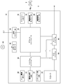
- FIG. 2 shows the hardware configuration of the information processing device 10.
- the information processing device 10 includes a main power button 20, a power ON LED 21, a standby LED 22, a system controller 24, a clock 26, a device controller 30, a media drive 32, a USB module 34, a flash memory 36, a wireless communication module 38, and wired communication. It includes a module 40, a subsystem 50, and a main system 60.
- the main system 60 includes a main CPU (Central Processing Unit), a memory and a memory controller which are main storage devices, a GPU (Graphics Processing Unit), and the like.
- the GPU is mainly used for arithmetic processing of a game program. These functions may be configured as system-on-chip and formed on one chip.
- the main CPU has a function of executing a game program recorded in the auxiliary storage device 2 or the ROM medium 44.
- the subsystem 50 includes a sub CPU, a memory as a main storage device, a memory controller, and the like, does not have a GPU, and does not have a function of executing a game program.
- the number of circuit gates of the sub CPU is smaller than the number of circuit gates of the main CPU, and the operating power consumption of the sub CPU is smaller than the operating power consumption of the main CPU.
- the sub CPU operates even while the main CPU is in the standby state, and its processing function is limited in order to keep the power consumption low.
- the main power button 20 is an input unit for inputting operations from the user, and is provided on the front surface of the housing of the information processing device 10 to turn on or off the power supply to the main system 60 of the information processing device 10. Manipulated for.
- the power ON LED 21 lights up when the main power button 20 is turned on, and the standby LED 22 lights up when the main power button 20 is turned off.
- the system controller 24 detects the user pressing the main power button 20. When the main power button 20 is pressed while the main power is off, the system controller 24 acquires the pressing operation as an "on instruction", while the main power is on when the main power is on. When the button 20 is pressed, the system controller 24 acquires the pressing operation as an "off instruction”.
- the clock 26 is a real-time clock that generates current date and time information and supplies it to the system controller 24, the subsystem 50, and the main system 60.
- the device controller 30 is configured as an LSI (Large-Scale Integrated Circuit) that executes information transfer between devices like a south bridge. As shown in the figure, devices such as a system controller 24, a media drive 32, a USB module 34, a flash memory 36, a wireless communication module 38, a wired communication module 40, a subsystem 50, and a main system 60 are connected to the device controller 30. NS.
- the device controller 30 absorbs the difference in electrical characteristics and the difference in data transfer speed of each device, and controls the timing of data transfer.
- the media drive 32 is a drive device that mounts and drives application software such as a game and a ROM medium 44 that records license information, and reads a program, data, or the like from the ROM medium 44.
- the ROM medium 44 may be a read-only recording medium such as an optical disc, a magneto-optical disc, or a Blu-ray disc.
- the USB module 34 is a module that connects to an external device with a USB cable.
- the USB module 34 may be connected to the auxiliary storage device 2 and the camera 7 with a USB cable.
- the flash memory 36 is an auxiliary storage device that constitutes an internal storage.
- the wireless communication module 38 uses a communication protocol such as a Bluetooth (registered trademark) protocol or an IEEE 802.11 protocol to wirelessly communicate with, for example, an input device 6.
- the wired communication module 40 communicates with an external device by wire and connects to an external network via the AP8.
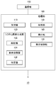
- FIG. 3 shows a functional block of the information processing device 10.
- the information processing device 10 includes a processing unit 100 and a communication unit 102, and the processing unit 100 includes a reception unit 110, a system image generation unit 120, an acquisition unit 130, an execution unit 140, and a display control unit 150.
- each element described as a functional block that performs various processes can be composed of a circuit block, a memory, and other LSIs in terms of hardware, and system software and memory in terms of software. It is realized by the game program loaded in. Therefore, it is understood by those skilled in the art that these functional blocks can be realized in various forms by hardware only, software only, or a combination thereof, and is not limited to any of them.
- the communication unit 102 is represented as a configuration having the functions of the wireless communication module 38 and the wired communication module 40 shown in FIG.
- the communication unit 102 receives the operation information in which the user operates the input unit of the input device 6, and the reception unit 110 receives the operation information received by the communication unit 102.
- the system image generation unit 120 has a function of generating a menu image including a plurality of display elements.
- the display element included in the menu image may be a GUI element such as a game icon or an icon of an application other than the game.
- the execution unit 140 executes a function associated with the selected icon. For example, when a game icon is selected and a determination operation is performed, the execution unit 140 executes a game program associated with the selected icon to generate a game image and a game sound.
- the display control unit 150 causes the output device 4 to display the game image generated by the execution unit 140.
- the system image generation unit 120 includes an arrangement unit 122, a display processing unit 124, and a specific unit 126.
- the arrangement unit 122 arranges a plurality of icons on the two-dimensional coordinates constituting the screen to generate a menu image.
- the arrangement unit 122 generates a menu image triggered by various user operations. For example, when the main power button 20 is turned on and the information processing device 10 is activated, the arrangement unit 122 generates a menu image.
- the display control unit 150 may display the menu image on the output device 4.
- FIG. 4 shows an example of a menu image.
- the menu image shown in FIG. 4 may be an initial image displayed on the output device 4 when the information processing device 10 is activated.
- the arrangement unit 122 generates a menu image in which a plurality of icons 200a, 200b, 200c, 200d, 200e, 200f, 200g, 200h, 200i (hereinafter, referred to as "icon 200" unless otherwise specified) are arranged.
- the arrangement unit 122 may arrange a plurality of icons 200 according to a predetermined layout (format). In the embodiment, the arrangement unit 122 arranges the icon 200, which is a GUI element to which the function is associated, but other types of display elements may be arranged.
- the display processing unit 124 displays the icon 200 in the selected state in a predetermined mode indicating that the icon 200 is selected.
- the icon 200a arranged in the upper left corner of the screen is in the selected state, and the display processing unit 124 arranges the focus frame 202 indicating that the icon 200a is selected around the icon 200a. ..
- the user can recognize that the icon 200a is selected by checking the icon surrounded by the focus frame 202.
- the display processing unit 124 displays the icon 200a in the selected state larger than the standard size, blinks the icon 200a itself, and causes the icon 200a to blink. The user may be able to recognize that it is in the selected state.
- the input device 6 operated by the user is provided with a direction controller such as a direction key and / or an analog stick.
- a direction controller such as a direction key and / or an analog stick.
- the user operates the direction controller of the input device 6 when moving the focus frame 202 and selecting the icon 200.
- the direction controller may be composed of four direction keys that allow the user to specify four directions of up, down, left, and right.
- the reception unit 110 accepts the operation of the direction controller as an operation of selecting the icon 200.
- the identification unit 126 identifies the destination of the focus frame 202, that is, the icon 200 to be selected, based on the direction keys operated by the user.
- FIG. 5 shows an example of a menu image in which the focus frame 202 has been moved.
- the focus frame 202 is arranged around the icon 200g.
- the specific unit 126 specifies the icon 200g selected by the operation of the right direction key.
- the plurality of icons 200 are arranged according to a predetermined layout by the arrangement unit 122, and the movement destination of the focus frame 202 when the direction key is operated is defined at each position where the icons 200 are arranged. ..
- the focus frame 202 moves to the position of the icon 200g by operating the right arrow key, and the focus frame 202 moves to the position of the icon 200b by operating the down arrow key. Is defined to do. It is also defined that the focus frame 202 does not move at the position of the upper left corner where the icon 200a is arranged even if the left arrow key and the up arrow key are operated.
- the direction controller is the up / down / left / right direction keys.
- the movement destination of the focus frame 202 is the direction in which the analog stick is tilted. It may be defined in the angle range of.
- the specifying unit 126 specifies the position of the focus frame 202 as the moving destination according to the definition information of the moving destination.
- the specific unit 126 specifies the icon 200g to be selected by the operation of the right direction key, and the display processing unit 124 ,
- the focus frame 202 is arranged around the icon 200g.
- the user can easily predict the destination of the focus frame 202 by operating the direction keys. For example, when the user operates the right arrow key, the focus frame 202 moves to the position of the icon arranged on the right side, and when the user operates the down arrow key, the focus frame 202 moves to the position of the icon arranged directly below. do.
- the display processing unit 124 of the embodiment displays an effect indicating that the state in which the icon 200a is selected is changed to the state in which the icon 200g is selected before displaying the focus frame 202 around the icon 200g. conduct. That is, the display processing unit 124 inserts an effect indicating that the selected icon is changed between the display of the menu image shown in FIG. 4 and the display of the menu image shown in FIG.
- the icon 200a surrounded before the movement of the focus frame 202 will be referred to as a “first icon 200a”
- the icon 200g surrounded after the movement of the focus frame 202 will be referred to as a “second icon 200g”.
- the specific unit 126 moves the focus frame 202 to the second icon. Identify the position at 200g.
- the display processing unit 124 performs an effect display indicating that the state in which the first icon 200a is selected is changed to the state in which the second icon 200g is selected. During the effect display, the display processing unit 124 hides the focus frame 202.
- FIG. 6 shows an example of the effect display when the icon 200 in the selected state is changed.
- the moving direction 204 indicates the direction from the first icon 200a to the second icon 200g.
- the moving direction 204 in FIG. 6 is drawn for the purpose of illustrating the moving direction of the effect element 210, and is displayed as a part of the effect display and is not visible to the user, but the movement destination is made clearer. It may be displayed as a part of the effect display.
- the display processing unit 124 carries out an effect display regarding the direction from the display position of the first icon 200a to the display position of the second icon 200g between the display position of the first icon 200a and the display position of the second icon 200g. Specifically, the display processing unit 124 performs an effect display in which the effect element 210 is moved between the display position of the first icon 200a and the display position of the second icon 200 g.
- the effect element 210 has at least a high-luminance area, and the display processing unit 124 causes the effect element 210 to jump out of the first icon 200a and move at high speed so as to jump into the second icon 200g.
- FIG. 7 shows how the effect element 210 jumps into the second icon 200 g.
- the user can recognize the position of the second icon 200g by moving the effect element 210 having a high-brightness region in a straight line from the first icon 200a to the second icon 200g.
- the display processing unit 124 changes the shape of the effect element 210 from the shape of the first icon 200a to the shape of the second icon 200g.
- the shape of the effect element 210 is substantially the same as the shape of the first icon 200a, and when the effect element 210 jumps into the second icon 200g, the shape of the effect element 210 is. It is substantially the same as the shape of the second icon 200 g.
- the display processing unit 124 may gradually (continuously or stepwise) deform the effect element 210 from the display position of the first icon 200a to the display position of the second icon 200 g. preferable.
- the vertical width of the second icon 200g is longer than the vertical width of the first icon 200a. Therefore, when the effect element 210 is moved from the display position of the first icon 200a to the display position of the second icon 200 g, the display processing unit 124 gradually increases the vertical width of the effect element 210 to the second icon 200 g. When overlapping, the vertical width of the effect element 210 is made equal to the vertical width of the second icon 200 g.
- the display processing unit 124 displays the focus frame 202 around the second icon 200g after superimposing the effect element 210 having a high-luminance region on the second icon 200g.
- the first icon 200a and the second icon 200g have a rectangular shape, but one or both of them may have a rectangular shape, for example, a round shape or a triangular shape. Even in that case, the display processing unit 124 deforms the moving effect element 210 from the shape of the moving source first icon 200a to the shape of the moving destination second icon 200g, so that the focus frame 202 It is possible to make the user recognize the pseudo movement.
- the display processing unit 124 may determine the moving speed of the effect element 210 according to the distance between the display position of the first icon 200a and the display position of the second icon 200g. Specifically, the display processing unit 124 completes the effect display in the same predetermined time regardless of the distance between the first icon 200a and the second icon 200g. Therefore, if the distance is relatively long, the moving speed is relatively high, and if the distance is relatively short, the moving speed is relatively short.
- the purpose of the effect display is to make the user recognize the second icon 200 g as the movement destination. Therefore, the moving speed within the effect display period is slower when the effect element 210 enters the display position of the second icon 200 g than when the effect element 210 exits the display position of the first icon 200a. It is preferable that the second icon 200 g is easily recognized by the user.
- the display processing unit 124 performs an effect display in which at least one of the first icon 200a and the second icon 200g appears to be deformed according to the moving direction 204.
- the effect element 210 having a shape close to the second icon 200 g overlaps with the second icon 200 g, the effect is such that the second icon 200 g extends and deforms in the moving direction 204. Due to such an effect, the user can easily recognize that the second icon 200 g has been selected.
- the display processing unit 124 arranges the focus frame 202 around the second icon 200 g, as shown in FIG.
- the information processing device 10 accesses the content server via the AP8, and the acquisition unit 130 acquires a thumbnail image of the content from the content server.
- the content server of the embodiment first transmits the low-resolution thumbnail image and then outputs the high-resolution thumbnail image so that the display control unit 150 can quickly display the thumbnail image of the content on the output device 4.
- the low-resolution thumbnail image transmitted first is referred to as a "first thumbnail image”
- the high-resolution thumbnail image transmitted subsequently is referred to as a "second thumbnail image”.
- the first thumbnail image may be an image generated by lowering the resolution of the second thumbnail image and reducing the data size.
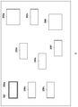
- the arrangement unit 122 arranges the first thumbnail image at a predetermined position on the two-dimensional coordinates constituting the screen, and the display control unit 150 displays the first thumbnail image. do.
- FIG. 8 shows a display example of four first thumbnail images. Since the resolution of the first thumbnail image displayed in FIG. 8 is low, the user recognizes the displayed first thumbnail image as a coarse image. In this case, the purpose of promptly displaying the thumbnail image is achieved, but the coarse image gives a cheesy impression, which is not preferable.
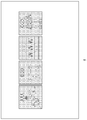
- FIG. 9 shows a display example of the first thumbnail image in the modified example.
- the display processing unit 124 hides and displays a part of the first thumbnail image.
- the display processing unit 124 superimposes a mask having a plurality of scattered openings (holes) on the first thumbnail image so that the first thumbnail image is displayed only through the plurality of openings. ing.
- a mask having an opening of 20 or more in the vertical direction and 20 or more in the horizontal direction on one first thumbnail image at substantially equal intervals the user can confirm a vague outline of the thumbnail.
- the modified example instead of directly displaying the entire coarse image as shown in FIG. 8, only a part of the coarse image is displayed so that the user does not notice the roughness of the image. ..
- the acquisition unit 130 acquires the second thumbnail image from the content server while the display control unit 150 hides and displays a part of the first thumbnail image
- the arrangement unit 122 is on the two-dimensional coordinates constituting the screen.
- a second thumbnail image is placed in place of the first thumbnail image and the mask.
- the display control unit 150 displays the second thumbnail image in place of the first thumbnail image that was partially hidden and displayed.
- the outline of the above modified example is as follows.
- the image display method of the modified example is Steps to get a low resolution first image, A step to hide and display a part of the acquired first image, Steps to get a high resolution second image, The step of displaying the second image instead of the first image, To be equipped.
- the present invention can be used in the technical field of displaying a plurality of display elements on a screen.
- 1 Information processing system, 10 ... Information processing device, 100 ... Processing unit, 102 ... Communication unit, 110 ... Reception unit, 120 ... System image generation unit, 122 ... Arrangement unit, 124 ... Display processing unit, 126 ... Specific unit, 130 ... Acquisition unit, 140 ... Execution unit, 150 ... Display control unit.
Landscapes
- Engineering & Computer Science (AREA)
- General Engineering & Computer Science (AREA)
- Theoretical Computer Science (AREA)
- Human Computer Interaction (AREA)
- Physics & Mathematics (AREA)
- General Physics & Mathematics (AREA)
- User Interface Of Digital Computer (AREA)
Priority Applications (2)
| Application Number | Priority Date | Filing Date | Title |
|---|---|---|---|
| EP20916732.9A EP4099143A4 (en) | 2020-01-28 | 2020-09-28 | IMAGE PROCESSING DEVICE AND METHOD |
| US17/792,204 US11880548B2 (en) | 2020-01-28 | 2020-09-28 | Image processing apparatus and image processing method |
Applications Claiming Priority (2)
| Application Number | Priority Date | Filing Date | Title |
|---|---|---|---|
| JP2020-011904 | 2020-01-28 | ||
| JP2020011904A JP7504603B2 (ja) | 2020-01-28 | 2020-01-28 | 画像処理装置および画像処理方法 |
Publications (1)
| Publication Number | Publication Date |
|---|---|
| WO2021152911A1 true WO2021152911A1 (ja) | 2021-08-05 |
Family
ID=77079680
Family Applications (1)
| Application Number | Title | Priority Date | Filing Date |
|---|---|---|---|
| PCT/JP2020/036726 Ceased WO2021152911A1 (ja) | 2020-01-28 | 2020-09-28 | 画像処理装置および画像処理方法 |
Country Status (4)
| Country | Link |
|---|---|
| US (1) | US11880548B2 (enExample) |
| EP (1) | EP4099143A4 (enExample) |
| JP (1) | JP7504603B2 (enExample) |
| WO (1) | WO2021152911A1 (enExample) |
Citations (3)
| Publication number | Priority date | Publication date | Assignee | Title |
|---|---|---|---|---|
| JPH1040018A (ja) * | 1996-04-24 | 1998-02-13 | Sharp Corp | マウスカーソルの制御装置及びマウスカーソルの制御プログラムを記録した記録媒体 |
| JP2001155188A (ja) * | 1999-09-14 | 2001-06-08 | Sony Computer Entertainment Inc | 表示オブジェクト選択受付方法、記憶媒体およびプログラム実行装置 |
| JP2012073995A (ja) * | 2010-09-03 | 2012-04-12 | Denso Wave Inc | タッチパネル式入力端末の入力制御装置 |
Family Cites Families (10)
| Publication number | Priority date | Publication date | Assignee | Title |
|---|---|---|---|---|
| JPS6440018A (en) | 1987-08-06 | 1989-02-10 | Hidemi Jutaku Kk | Toilet bowl |
| US5687331A (en) * | 1995-08-03 | 1997-11-11 | Microsoft Corporation | Method and system for displaying an animated focus item |
| US8250490B2 (en) * | 2006-12-18 | 2012-08-21 | Canon Kabushiki Kaisha | Display image control apparatus |
| US9003326B2 (en) * | 2008-09-23 | 2015-04-07 | Apple Inc. | Indicating input focus by showing focus transitions |
| US9021386B1 (en) * | 2009-05-28 | 2015-04-28 | Google Inc. | Enhanced user interface scrolling system |
| JP4991829B2 (ja) * | 2009-11-09 | 2012-08-01 | 株式会社デンソー | 遠隔操作デバイス用表示制御装置 |
| JP5029683B2 (ja) * | 2009-12-29 | 2012-09-19 | コニカミノルタビジネステクノロジーズ株式会社 | 画像処理装置及び同装置の表示制御方法並びに表示制御プログラム |
| EP2664983A3 (en) * | 2012-05-17 | 2018-01-03 | LG Electronics, Inc. | Mobile terminal and control method therefor |
| US10120540B2 (en) * | 2013-03-14 | 2018-11-06 | Samsung Electronics Co., Ltd. | Visual feedback for user interface navigation on television system |
| DE102018202657A1 (de) * | 2018-02-22 | 2019-08-22 | Bayerische Motoren Werke Aktiengesellschaft | Vorrichtung und verfahren zum steuern von fahrzeugfunktionen sowie fahrzeug |
-
2020
- 2020-01-28 JP JP2020011904A patent/JP7504603B2/ja active Active
- 2020-09-28 US US17/792,204 patent/US11880548B2/en active Active
- 2020-09-28 WO PCT/JP2020/036726 patent/WO2021152911A1/ja not_active Ceased
- 2020-09-28 EP EP20916732.9A patent/EP4099143A4/en active Pending
Patent Citations (3)
| Publication number | Priority date | Publication date | Assignee | Title |
|---|---|---|---|---|
| JPH1040018A (ja) * | 1996-04-24 | 1998-02-13 | Sharp Corp | マウスカーソルの制御装置及びマウスカーソルの制御プログラムを記録した記録媒体 |
| JP2001155188A (ja) * | 1999-09-14 | 2001-06-08 | Sony Computer Entertainment Inc | 表示オブジェクト選択受付方法、記憶媒体およびプログラム実行装置 |
| JP2012073995A (ja) * | 2010-09-03 | 2012-04-12 | Denso Wave Inc | タッチパネル式入力端末の入力制御装置 |
Non-Patent Citations (1)
| Title |
|---|
| See also references of EP4099143A4 * |
Also Published As
| Publication number | Publication date |
|---|---|
| EP4099143A1 (en) | 2022-12-07 |
| US11880548B2 (en) | 2024-01-23 |
| EP4099143A4 (en) | 2024-02-28 |
| US20230050265A1 (en) | 2023-02-16 |
| JP2021117839A (ja) | 2021-08-10 |
| JP7504603B2 (ja) | 2024-06-24 |
Similar Documents
| Publication | Publication Date | Title |
|---|---|---|
| KR102407623B1 (ko) | 사용자 단말 장치 및 이의 제어 방법 | |
| JP5681191B2 (ja) | コンピュータ周辺機器上にアプリケーションインターフェイス部を提供する方法および装置 | |
| JP7390992B2 (ja) | 情報処理装置および画像表示方法 | |
| CN105191330A (zh) | 显示装置及其图形用户界面屏幕提供方法 | |
| CN101833391A (zh) | 信息处理设备、信息处理方法及程序 | |
| US20160202869A1 (en) | User terminal device and method for controlling the same | |
| JPWO2015025345A1 (ja) | 情報表示装置、情報表示方法および情報表示プログラム | |
| KR101803311B1 (ko) | 디스플레이 장치 및 이의 ui 제공 방법 | |
| WO2021128929A1 (zh) | 一种全景应用中图像渲染的方法及终端设备 | |
| JP6153450B2 (ja) | 情報処理システムおよび情報処理装置 | |
| JP2008146495A (ja) | 表示制御システム、表示制御装置、表示制御方法および表示制御プログラム、画像出力装置、画像出力方法および画像出力プログラム、ならびに、表示装置 | |
| CN108353204A (zh) | 显示装置及其控制方法 | |
| US20140317549A1 (en) | Method for Controlling Touchscreen by Using Virtual Trackball | |
| JP2021117839A (ja) | 画像処理装置および画像処理方法 | |
| TW201409350A (zh) | 影像外接裝置的處理方法以及影像外接裝置 | |
| KR20170125004A (ko) | 디스플레이 장치 및 그 ui 화면 제공 방법 | |
| JPWO2020148949A1 (ja) | 情報処理装置および画像生成方法 | |
| JP6716519B2 (ja) | 表示装置及び表示方法 | |
| US20180067632A1 (en) | User terminal apparatus and control method thereof | |
| KR20170028001A (ko) | 전자 장치 및 이의 제어 방법 | |
| CN114281284A (zh) | 显示设备和图像显示方法 | |
| JP6752311B2 (ja) | 表示装置及び表示方法 | |
| WO2022071178A1 (ja) | 情報処理装置およびプログラム | |
| JP5511023B2 (ja) | 映像表示システム及び方法 | |
| JP7289208B2 (ja) | プログラム、情報処理装置、および方法 |
Legal Events
| Date | Code | Title | Description |
|---|---|---|---|
| 121 | Ep: the epo has been informed by wipo that ep was designated in this application |
Ref document number: 20916732 Country of ref document: EP Kind code of ref document: A1 |
|
| NENP | Non-entry into the national phase |
Ref country code: DE |
|
| ENP | Entry into the national phase |
Ref document number: 2020916732 Country of ref document: EP Effective date: 20220829 |