WO2021152416A1 - 学習データ生成装置、不良識別システム - Google Patents
学習データ生成装置、不良識別システム Download PDFInfo
- Publication number
- WO2021152416A1 WO2021152416A1 PCT/IB2021/050330 IB2021050330W WO2021152416A1 WO 2021152416 A1 WO2021152416 A1 WO 2021152416A1 IB 2021050330 W IB2021050330 W IB 2021050330W WO 2021152416 A1 WO2021152416 A1 WO 2021152416A1
- Authority
- WO
- WIPO (PCT)
- Prior art keywords
- image data
- data
- less
- ellipse
- polygon
- Prior art date
- Legal status (The legal status is an assumption and is not a legal conclusion. Google has not performed a legal analysis and makes no representation as to the accuracy of the status listed.)
- Ceased
Links
Images










Classifications
-
- G—PHYSICS
- G06—COMPUTING OR CALCULATING; COUNTING
- G06V—IMAGE OR VIDEO RECOGNITION OR UNDERSTANDING
- G06V10/00—Arrangements for image or video recognition or understanding
- G06V10/70—Arrangements for image or video recognition or understanding using pattern recognition or machine learning
- G06V10/82—Arrangements for image or video recognition or understanding using pattern recognition or machine learning using neural networks
-
- G—PHYSICS
- G06—COMPUTING OR CALCULATING; COUNTING
- G06T—IMAGE DATA PROCESSING OR GENERATION, IN GENERAL
- G06T7/00—Image analysis
- G06T7/0002—Inspection of images, e.g. flaw detection
- G06T7/0004—Industrial image inspection
- G06T7/0008—Industrial image inspection checking presence/absence
-
- G—PHYSICS
- G06—COMPUTING OR CALCULATING; COUNTING
- G06N—COMPUTING ARRANGEMENTS BASED ON SPECIFIC COMPUTATIONAL MODELS
- G06N20/00—Machine learning
-
- G—PHYSICS
- G06—COMPUTING OR CALCULATING; COUNTING
- G06T—IMAGE DATA PROCESSING OR GENERATION, IN GENERAL
- G06T1/00—General purpose image data processing
-
- G—PHYSICS
- G06—COMPUTING OR CALCULATING; COUNTING
- G06T—IMAGE DATA PROCESSING OR GENERATION, IN GENERAL
- G06T5/00—Image enhancement or restoration
- G06T5/50—Image enhancement or restoration using two or more images, e.g. averaging or subtraction
-
- G—PHYSICS
- G06—COMPUTING OR CALCULATING; COUNTING
- G06T—IMAGE DATA PROCESSING OR GENERATION, IN GENERAL
- G06T7/00—Image analysis
- G06T7/0002—Inspection of images, e.g. flaw detection
- G06T7/0004—Industrial image inspection
-
- G—PHYSICS
- G06—COMPUTING OR CALCULATING; COUNTING
- G06T—IMAGE DATA PROCESSING OR GENERATION, IN GENERAL
- G06T7/00—Image analysis
- G06T7/60—Analysis of geometric attributes
- G06T7/62—Analysis of geometric attributes of area, perimeter, diameter or volume
-
- G—PHYSICS
- G06—COMPUTING OR CALCULATING; COUNTING
- G06V—IMAGE OR VIDEO RECOGNITION OR UNDERSTANDING
- G06V10/00—Arrangements for image or video recognition or understanding
- G06V10/20—Image preprocessing
- G06V10/25—Determination of region of interest [ROI] or a volume of interest [VOI]
-
- G—PHYSICS
- G06—COMPUTING OR CALCULATING; COUNTING
- G06V—IMAGE OR VIDEO RECOGNITION OR UNDERSTANDING
- G06V10/00—Arrangements for image or video recognition or understanding
- G06V10/40—Extraction of image or video features
- G06V10/56—Extraction of image or video features relating to colour
-
- G—PHYSICS
- G06—COMPUTING OR CALCULATING; COUNTING
- G06V—IMAGE OR VIDEO RECOGNITION OR UNDERSTANDING
- G06V10/00—Arrangements for image or video recognition or understanding
- G06V10/40—Extraction of image or video features
- G06V10/60—Extraction of image or video features relating to illumination properties, e.g. using a reflectance or lighting model
-
- G—PHYSICS
- G06—COMPUTING OR CALCULATING; COUNTING
- G06V—IMAGE OR VIDEO RECOGNITION OR UNDERSTANDING
- G06V10/00—Arrangements for image or video recognition or understanding
- G06V10/70—Arrangements for image or video recognition or understanding using pattern recognition or machine learning
- G06V10/77—Processing image or video features in feature spaces; using data integration or data reduction, e.g. principal component analysis [PCA] or independent component analysis [ICA] or self-organising maps [SOM]; Blind source separation
- G06V10/772—Determining representative reference patterns, e.g. averaging or distorting patterns; Generating dictionaries
-
- G—PHYSICS
- G06—COMPUTING OR CALCULATING; COUNTING
- G06V—IMAGE OR VIDEO RECOGNITION OR UNDERSTANDING
- G06V10/00—Arrangements for image or video recognition or understanding
- G06V10/70—Arrangements for image or video recognition or understanding using pattern recognition or machine learning
- G06V10/77—Processing image or video features in feature spaces; using data integration or data reduction, e.g. principal component analysis [PCA] or independent component analysis [ICA] or self-organising maps [SOM]; Blind source separation
- G06V10/774—Generating sets of training patterns; Bootstrap methods, e.g. bagging or boosting
-
- G—PHYSICS
- G06—COMPUTING OR CALCULATING; COUNTING
- G06V—IMAGE OR VIDEO RECOGNITION OR UNDERSTANDING
- G06V10/00—Arrangements for image or video recognition or understanding
- G06V10/70—Arrangements for image or video recognition or understanding using pattern recognition or machine learning
- G06V10/77—Processing image or video features in feature spaces; using data integration or data reduction, e.g. principal component analysis [PCA] or independent component analysis [ICA] or self-organising maps [SOM]; Blind source separation
- G06V10/774—Generating sets of training patterns; Bootstrap methods, e.g. bagging or boosting
- G06V10/7747—Organisation of the process, e.g. bagging or boosting
-
- G—PHYSICS
- G06—COMPUTING OR CALCULATING; COUNTING
- G06V—IMAGE OR VIDEO RECOGNITION OR UNDERSTANDING
- G06V20/00—Scenes; Scene-specific elements
- G06V20/70—Labelling scene content, e.g. deriving syntactic or semantic representations
-
- G—PHYSICS
- G01—MEASURING; TESTING
- G01N—INVESTIGATING OR ANALYSING MATERIALS BY DETERMINING THEIR CHEMICAL OR PHYSICAL PROPERTIES
- G01N21/00—Investigating or analysing materials by the use of optical means, i.e. using sub-millimetre waves, infrared, visible or ultraviolet light
- G01N21/84—Systems specially adapted for particular applications
- G01N21/88—Investigating the presence of flaws or contamination
- G01N21/8851—Scan or image signal processing specially adapted therefor, e.g. for scan signal adjustment, for detecting different kinds of defects, for compensating for structures, markings, edges
- G01N2021/8883—Scan or image signal processing specially adapted therefor, e.g. for scan signal adjustment, for detecting different kinds of defects, for compensating for structures, markings, edges involving the calculation of gauges, generating models
-
- G—PHYSICS
- G01—MEASURING; TESTING
- G01N—INVESTIGATING OR ANALYSING MATERIALS BY DETERMINING THEIR CHEMICAL OR PHYSICAL PROPERTIES
- G01N21/00—Investigating or analysing materials by the use of optical means, i.e. using sub-millimetre waves, infrared, visible or ultraviolet light
- G01N21/84—Systems specially adapted for particular applications
- G01N21/88—Investigating the presence of flaws or contamination
- G01N21/95—Investigating the presence of flaws or contamination characterised by the material or shape of the object to be examined
- G01N21/956—Inspecting patterns on the surface of objects
-
- G—PHYSICS
- G06—COMPUTING OR CALCULATING; COUNTING
- G06T—IMAGE DATA PROCESSING OR GENERATION, IN GENERAL
- G06T2207/00—Indexing scheme for image analysis or image enhancement
- G06T2207/10—Image acquisition modality
- G06T2207/10024—Color image
-
- G—PHYSICS
- G06—COMPUTING OR CALCULATING; COUNTING
- G06T—IMAGE DATA PROCESSING OR GENERATION, IN GENERAL
- G06T2207/00—Indexing scheme for image analysis or image enhancement
- G06T2207/20—Special algorithmic details
- G06T2207/20081—Training; Learning
-
- G—PHYSICS
- G06—COMPUTING OR CALCULATING; COUNTING
- G06T—IMAGE DATA PROCESSING OR GENERATION, IN GENERAL
- G06T2207/00—Indexing scheme for image analysis or image enhancement
- G06T2207/20—Special algorithmic details
- G06T2207/20084—Artificial neural networks [ANN]
-
- G—PHYSICS
- G06—COMPUTING OR CALCULATING; COUNTING
- G06T—IMAGE DATA PROCESSING OR GENERATION, IN GENERAL
- G06T2207/00—Indexing scheme for image analysis or image enhancement
- G06T2207/20—Special algorithmic details
- G06T2207/20212—Image combination
- G06T2207/20221—Image fusion; Image merging
-
- G—PHYSICS
- G06—COMPUTING OR CALCULATING; COUNTING
- G06T—IMAGE DATA PROCESSING OR GENERATION, IN GENERAL
- G06T2207/00—Indexing scheme for image analysis or image enhancement
- G06T2207/30—Subject of image; Context of image processing
- G06T2207/30108—Industrial image inspection
- G06T2207/30148—Semiconductor; IC; Wafer
Definitions
- One aspect of the present invention relates to a method of generating learning data. Further, one aspect of the present invention relates to a learning data generator. Further, one aspect of the present invention relates to a defect identification system.
- Visual inspection can be mentioned as a means for detecting defects in the semiconductor manufacturing process.
- Examples of the device (visual inspection device) for automatically performing the visual inspection include a pattern inspection device. Defects are detected and identified in the image data acquired by using the visual inspection device. When defects are detected and identified visually, there may be individual differences in the accuracy of detection and identification. Further, when the number of image data is large, it takes an enormous amount of time to detect and identify defects.
- Patent Document 1 when the inspection target signal is classified into normal and non-normal based on the learned first neural network and it is determined that the inspection target signal is non-normal, the trained first is used.
- An inspection device that classifies the types of defects based on the neural network of 2 is disclosed.
- Data expansion is a technique for increasing the number of training data (expanding the amount of training data) by generating a variant of training data based on the training data already prepared. Specifically, one or more operations such as horizontal and / or vertical shift, horizontal and / or vertical inversion, rotation, zoom in, and zoom out are performed on the already prepared training data. By executing, the training data of the variant is generated.
- the accuracy of defect identification may not be sufficiently improved only by the operation.
- one aspect of the present invention is to provide a method for generating learning data. Further, one aspect of the present invention is to provide a learning data generator. Further, one aspect of the present invention is to provide a defect identification system.
- One aspect of the present invention is a function of cutting out a part of the first image data in which only the region where the pattern is normal is captured as the second image data, and a pseudo defect corresponding to the area of the second image data.
- a function to generate a two-dimensional figure representing It is a learning data generation device having a function of giving.
- one aspect of the present invention corresponds to a function of cutting out a part of the first image data created by synthesizing a region containing no defects as the second image data and an area of the second image data.
- the two-dimensional figure is a first two-dimensional figure or a second two-dimensional figure, and the first two-dimensional figure is generated by designating a shape and a color, and a second.
- the two-dimensional figure of is preferably generated by cutting out the second image data.
- the first two-dimensional figure is a first polygon, an ellipse, or a double ellipse, and the second image data and the first polygon or ellipse are combined.
- a first label is given to the third image data generated by the above, and the third image data generated by synthesizing the second image data and the double ellipse is assigned to the third image data. It is preferable that a second label is given.
- the first polygon has the vertices of the first to n (n is an integer of 3 or more and 8 or less), and the points in the first polygon and the first polygon.
- the length of the line segment connecting each of the 1st vertex to the nth vertex is the length according to the normal distribution, and the average of the normal distribution is 0.05 times or more 0 times the long side of the second image data.
- the length is 25 times or less, the standard deviation is 0.2 times the average, and the color of the first polygon is 0 or more and 20 or less (decimal number) in each of the 256 gradations of RGB.
- the transparency of the color of the first polygon is preferably 0% or more and 10% or less.
- the major axis of the ellipse is 0.05 times or more and 0.25 times or less of the long side of the second image data
- the minor axis of the ellipse is 0 of the major axis.
- the length is 6 times or more and 1.0 times or less
- the color of the ellipse is 0 or more and 10 or less (expressed in decimal) in each of the 256 gradations of RGB, and the color of the ellipse is transparent.
- the rate is preferably 0% or more and 10% or less.
- the major axis of the double ellipse is 0.05 times or more and 0.25 times or less of the long side of the second image data
- the minor axis of the double ellipse is The length is 0.6 times or more and 1.0 times or less of the major axis
- the difference between the outer diameter and the inner diameter of the double ellipse is 5 pixels or more and 15 pixels or less
- the color of the double ellipse is 256.
- R is 150 or more and 170 or less (expressed in decimal)
- G is 60 or more and 80 or less (expressed in decimal)
- B is 20 or more and 40 or less (expressed in decimal).
- the color transparency of the bi-elliptic transfer is preferably 50% or more and 75% or less.
- the second two-dimensional figure is a second polygon
- the third image data generated by synthesizing the second image data and the second polygon Is preferably labeled with a third label.
- the second polygon is cut out from the second image data rotated at an angle of 30 ° or more and 150 ° or less around a point located in the second image data.
- the quadrangle has a center of gravity as a point, and each of the long side and the short side is 0.1 times or more and 0.25 times or less the length of the long side of the second image data. Is preferable.
- the learning data generation device has a function of performing gamma conversion on the third image data and a function of performing noise addition or blurring processing on the third image data. , It is preferable to have.
- Another aspect of the present invention is a defect identification system for identifying defects
- the defect identification system includes the learning data generation device, a database, and an identification device
- the database includes a first method.
- the image data, the fourth image data with the label, and the fifth image data without the label are stored, and the identification device uses the trained model as the fifth image data. It has a function to identify the included defects.
- a trained model is generated based on a learning data set composed of a third image data and a fourth image data.
- a method for generating learning data it is possible to provide a method for generating learning data. Further, according to one aspect of the present invention, a learning data generation device can be provided. Further, according to one aspect of the present invention, a defect identification system can be provided.
- the effect of one aspect of the present invention is not limited to the effects listed above.
- the effects listed above do not preclude the existence of other effects.
- the other effects are the effects not mentioned in this item, which are described below. Effects not mentioned in this item can be derived from those described in the description, drawings, etc. by those skilled in the art, and can be appropriately extracted from these descriptions.
- one aspect of the present invention has at least one of the above-listed effects and / or other effects. Therefore, one aspect of the present invention may not have the effects listed above in some cases.
- FIG. 1 is a flowchart showing an example of a method of generating image data.
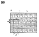
- FIG. 2 is a diagram illustrating a method of cutting out image data.
- 3A to 3E are diagrams for explaining a two-dimensional figure.
- 4A to 4D are diagrams for explaining image data.
- FIG. 5 is a flowchart showing an example of a method of generating image data.
- FIG. 6 is a flowchart showing an example of a method of generating a trained discriminative model.
- FIG. 7 is a flowchart showing an example of a method for identifying defects.
- 8A and 8B are block diagrams showing an example of a defect identification system.
- 9A and 9B are block diagrams showing an example of a defect identification system.
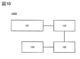
- FIG. 10 is a block diagram showing an example of a defect identification system.
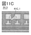
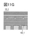
- 11A to 11I are diagrams for explaining an example of image data.
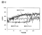
- FIG. 12 is a diagram showing changes in the accuracy rate for each discriminative model.
- the data set used for learning and evaluation of the machine learning model is referred to as a learning data set.
- the training data set is divided into training data (also referred to as training data) and test data (also referred to as evaluation data). Further, the training data may be divided into training data and verification data. The test data may be divided in advance from the training data set.
- the learning data is the data used for learning the machine learning model.
- the verification data is data used for evaluating the learning result of the machine learning model.
- Test data is data used to evaluate a machine learning model. When machine learning is supervised learning, the learning data, validation data, and test data are labeled.
- FIG. 1 is a flowchart showing an example of a method of generating learning data.
- FIG. 1 is also a flowchart illustrating a flow of processing executed by the learning data generator.
- p is an integer of 2 or more training data. Note that p may be set in advance or may be specified before the user generates learning data.
- the generated learning data is used for learning the discriminative model described later.
- the discriminative model is one of the models of supervised learning.
- the data input to the discriminative model is image data. Therefore, the learning data generated by the above method is image data to which a label is attached.
- p pieces of training data are referred to as p pieces of image data 12 (image data 12_1 to image data 12_p). That is, each of the image data 12_1 to the image data 12_p is given a label corresponding to the defect.
- the method for generating the learning data includes steps S011 to S014 as shown in FIG.
- step S011 to step S014 may be collectively referred to as step S002.
- the image data 10 is acquired.
- the image data 10 is image data obtained by capturing only a region that does not include defects.
- the image data may be referred to as image data that does not include defects.
- the image data 10 is image data created by synthesizing a plurality of regions that do not include defects.
- Image data 12_1 to image data 12_p may be generated in order from image data 12_1.
- steps S011 to S013 a method of generating image data 12_i (i is an integer of 1 or more and p or less) will be described.
- Step S011 is a step of cutting out image data 11_i from the image data 10. That is, the image data 11_i is a part of the image data 10. The details of the process of cutting out the image data 11_i from the image data 10 will be described later.
- Step S012 is a step of generating a figure (sometimes called a pseudo-defect) that pseudo-expresses the characteristics (shape, color, etc.) of the defect.
- the pseudo defect is represented by a two-dimensional figure. Details of the two-dimensional figure will be described later.
- the pseudo defect generated in step S012 is referred to as a two-dimensional figure 31_i.
- Step S013 is a step of synthesizing the image data 11_i and the two-dimensional figure 31_i to generate the image data 12_i.
- the operation of synthesizing the image data 11_i and the two-dimensional figure 31_i is an operation of superimposing the two-dimensional figure 31_i on the image data 11_i.
- the image data 12_i can be given a label corresponding to the defect considered when the two-dimensional figure 31_i is generated.
- Step S014 is a step of determining whether or not p image data 12 are generated.
- the number of the generated image data 12 is p (YES)
- the generation of the image data 12 is terminated.
- the process proceeds to step S011.
- the image data 11_i + 1 cut out from the image data 10 has a different position from the image data 11_i.
- the locations where defects occur are not always the same. Therefore, by preparing the image data 11 having different regions to be cut out, it is possible to improve the accuracy of identifying defects.
- the image data 11_i + 1 may coincide with the position of the image data 11 other than the image data 11_i.
- image data 12_1 to image data 12_p can be generated. Since each of the image data 12_1 to the image data 12_p is given a label corresponding to the defect, the image data 12_1 to the image data 12_p can be used as learning data.
- the image data 10 captures only a region in which the semiconductor film, the insulating film, or the wiring pattern (hereinafter, simply referred to as a pattern) is normal in the semiconductor element in the middle of the manufacturing process or the semiconductor element in which the manufacturing process is completed. It is the image data that has been created.
- the image data may be referred to as image data having a normal pattern.
- the image data 10 is image data created by synthesizing a plurality of regions in which the pattern is normal.
- FIG. 2 is a diagram illustrating a method of cutting out image data 11_i from image data 10.
- the image data 11_i is referred to as the image data 11.
- the pattern included in the image data 10 shown in FIG. 2 is a schematic pattern, and does not indicate that the photographed pattern of the semiconductor element is designed as shown in FIG.
- the shape of the image data 11 is preferably rectangular.
- the rectangle has a long side length of a1 and a short side length of a2.
- the length a1 and the length a2 specify that the image data 11 fits in the image data 10. Therefore, at least the length a1 is set to be equal to or less than the length of the long side of the image data 10, and the length a2 is set to be equal to or less than the length of the short side of the image data 10. Further, the length a1 and the length a2 are designated so that the defect is contained in the image data 11.
- the ratio of the length a1 to the length a2 is preferably equal to the ratio of the length of the long side of the image data 10 to the length of the short side of the image data 10.
- the ratio of the length of the long side of the image data 10 to the length of the short side of the image data 10 is 4: 3: 3, for example, the length a1 may be 640 pixels and the length a2 may be 480 pixels.
- the ratio of the length a1 to the length a2 does not necessarily have to match the ratio of the length of the long side of the image data 10 to the length of the short side of the image data 10.
- the ratio of the length a1 to the length a2 may be different from the ratio of the length of the long side of the image data 10 to the length of the short side of the image data 10.
- the shape of the image data 11 may be a square.
- the long side of the rectangle and the short side of the image data 10 may be parallel, and the short side of the rectangle and the long side of the image data 10 may be parallel.
- the long side of the rectangle and the long side of the image data 10 do not have to be parallel or vertical.
- the position of the image data 11 is determined so that the image data 11 fits in the image data 10.
- the position of the image data 11 may be determined with reference to the center of gravity of the image data 11 or may be determined with reference to one of the vertices of the image data 11.
- the center of gravity of the image data 11 is determined by a uniform random number within the range 10s shown by the dotted line in FIG.
- the long side of the range 10s is located inside by a2 / 2 from the long side of the image data 10
- the short side of the range 10s is located inside by a1 / 2 from the short side of the image data 10. It is the range to be located.
- a uniform random number is a random number that follows a continuous uniform distribution so that all real numbers appear with the same probability within a specified interval or range.
- the step of determining the position of the image data 11 after specifying the length a1 and the length a2 has been described, but the step is not limited to this.
- the length a1 and the length a2 may be determined so that the image data 11 fits in the image data 10.
- the position of the image data 11 and the length a1 and the length a2 may be determined at the same time so that the image data 11 fits in the image data 10.
- the length of the long side and the length of the short side of the image data 11_i are the length of the long side and the short side of the other image data 11 (image data 11_1 to image data 11_p, except for the image data 11_i). It is preferable that they are equal to the length of each side. Further, it is preferable that the position of the image data 11_i is different from at least a part of the other image data 11 (image data 11_1 to image data 11_p, except for the image data 11_i). Thereby, as described above, the defect identification accuracy can be improved.
- Defects detected in the semiconductor manufacturing process include, for example, foreign matter contamination, film omission, pattern failure, film residue, film floating, and disconnection. These defects differ in characteristics such as shape and color. Therefore, the shape and color characteristics of the two-dimensional figure need to be different for each defect.
- the inclusion of foreign matter means that foreign matter originating from workers, materials, manufacturing equipment, working environment, etc. in the semiconductor manufacturing process is a substrate (semiconductor substrate such as silicon wafer, glass substrate, plastic substrate, metal substrate, etc. Refers to defects caused by adhesion on (SOI substrate, etc.).
- film loss refers to a defect caused by peeling off a normal pattern.
- pattern defect refers to a defect caused by the pattern not being formed as designed.
- a pattern defect is a defect in which the pattern is not formed as designed. Therefore, it is preferable that the two-dimensional figure expressing the pattern defect is generated by cutting out the image data 10.
- foreign matter is a defect that is unintentionally mixed.
- film loss is a defect in which the normal pattern is peeled off. Therefore, foreign matter and film shedding have a shape and color that is independent of the pattern. Therefore, it is preferable that the two-dimensional figure expressing the foreign matter and the film loss is generated by specifying the shape and the color.
- the two-dimensional figure expressing the foreign matter is defined as an ellipse or a first polygon.
- the two-dimensional figure expressing the film loss is a double ellipse.
- the two-dimensional figure expressing the pattern defect is referred to as a second polygon.
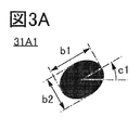
- FIG. 3A An ellipse 31A1 representing a foreign substance is shown in FIG. 3A.
- the ellipse 31A1 has a major axis length (major axis) of b1 and a minor axis length (minor axis) of b2.
- the major axis b1 of the ellipse 31A1 is 0.025 times or more and 0.4 times or less, preferably 0.05 times or more and 0.25 times or less of the length a1 of the long side of the image data 11.
- the major axis b1 may be a value determined by a uniform random number within a section of 0.05a1 or more and 0.25a1 or less.
- the minor axis b2 of the ellipse 31A1 is 0.5 times or more and 1.0 times or less, preferably 0.6 times or more and 1.0 times or less of the major axis b1 of the ellipse 31A1.
- the minor axis b2 may be a value determined by a uniform random number within a section of 0.6b1 or more and 1.0b1 or less.
- the ellipse 31A1 becomes a circle (perfect circle). Therefore, a circle (perfect circle) is also included as the shape of the ellipse 31A1.
- the angle between the line parallel to the long side of the image data 11 and the long axis of the ellipse 31A1 is defined as the rotation angle c1 of the ellipse 31A1.
- the rotation angle c1 may be, for example, a value determined by a uniform random number within a section of 0 ° or more and less than 360 °.
- the color of the ellipse 31A1 is preferably close to the color of the detected foreign matter.
- the color of the ellipse 31A1 is preferably black or a color close to black.
- the color of the ellipse 31A1 is R.
- G and B is 0 or more and 40 or less (expressed in decimal), preferably 0 or more and 20 or less (expressed in decimal).
- the color transmittance of the ellipse 31A1 is preferably low.
- the color transmittance of the ellipse 31A1 is 0% or more and 20% or less, preferably 0% or more and 10% or less.
- the ellipse 31A1 is not limited to the above shape, and may be oval or oval. When the shape of the ellipse 31A1 is oval, oval, or the like, it is preferable that the ellipse 31A1 has a shape similar to the above-mentioned shape.
- the arrangement of the ellipse 31A1 may be determined by a uniform random number so that the entire ellipse 31A1 fits within the range of the image data 11.
- First polygon An example of the shape, color, and arrangement of the first polygon representing a foreign object will be described with reference to FIG. 3B.
- the first polygon 31A2 representing a foreign substance is shown in FIG. 3B.
- the number of sides of the first polygon 31A2 is randomly determined from an integer of 3 or more and 8 or less.
- the number of sides of the first polygon 31A2 is n (n is an integer of 3 or more and 8 or less).
- the number of sides of the first polygon 31A2 is equal to the number of vertices of the first polygon 31A2. That is, the first polygon 31A2 is a polygon having n vertices and is an n-sided polygon. In FIG. 3B, the first polygon 31A2 is shown as a pentagon.
- the vertices of the first polygon 31A2 are referred to as the first vertices to the nth vertices.
- the line connecting the point in the first polygon 31A2 and the apex of the kth (k is an integer of 1 or more and n or less) is expressed as the kth line segment.
- the angle formed by the adjacent line segments (the angle formed by the kth line segment and the (k + 1) th line segment, where k is n, the nth line segment and the first line segment
- the angle of () is 360 / n [°].
- the angle between adjacent line segments is not limited to this. For example, it may be determined by a normal random number.
- the average of the normal distribution followed by the normal random number is, for example, 360 / n [°].
- the standard deviation of the normal distribution followed by the normal random number is, for example, 0.1 times or more and 0.3 times or less, preferably 0.2 times the average.
- each of the length d_1 to the length d_n is determined by a random number (also referred to as a normal random number) that follows a normal distribution.
- the average of the normal distribution is, for example, 0.025 times or more and 0.4 times or less, preferably 0.05 times or more and 0.25 times or less of the length a1 of the long side of the image data 11.
- the average is a value determined by a uniform random number within a section of 0.05a1 or more and 0.25a1 or less.
- the standard deviation of the normal distribution is, for example, 0.1 times or more and 0.3 times or less of the average, preferably 0.2 times the average.
- the angle formed by the line parallel to the long side of the image data 11 and the line segment connecting the above point and the first vertex (first line segment) is set to the rotation angle c2 of the first polygon 31A2. do.
- the rotation angle c2 is a line segment connecting a line parallel to the long side of the image data 11 and any one of the above point and the second vertex to the nth vertex (second line segment to nth). It may be the angle between one of the line segments) and the angle.
- the rotation angle c2 is, for example, a value determined by a uniform random number within a section of 0 ° or more and less than 360 °.
- the color of the first polygon 31A2 is preferably close to the color of the detected foreign matter.
- the color of the first polygon 31A2 is preferably black or a color close to black.
- the color of the first polygon 31A2 is 0 or more in each of R, G, and B. It is preferably 40 or less (expressed in decimal), preferably 0 or more and 20 or less (expressed in decimal).
- the color transmittance of the first polygon 31A2 is preferably low.
- the color transmittance of the first polygon 31A2 is 0% or more and 20% or less, preferably 0% or more and 10% or less.
- the arrangement of the first polygon 31A2 may be determined by a uniform random number so that the entire first polygon 31A2 falls within the range of the image data 11.
- Double ellipse An example of the shape, color, and arrangement of the bi-elliptic transfer representing the film loss will be described with reference to FIG. 3C.
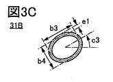
- FIG. 3C shows a double ellipse 31B expressing the film loss.
- the ellipse shown by the dotted line in FIG. 3C is a curve drawn by connecting points where the distance to the outer ellipse of the double ellipse 31B and the distance to the inner ellipse of the double ellipse 31B are equal.
- the ellipse shown by the dotted line in FIG. 3C has a major axis of b3 and a minor axis of b4.
- the major axis of the double ellipse 31B is represented by b3
- the minor axis is represented by b4
- the width of the double ellipse 31B (the distance between the outer ellipse and the inner ellipse) is represented by e1.
- the major axis b3 of the double ellipse 31B is 0.025 times or more and 0.4 times or less, preferably 0.05 times or more and 0.25 times or less of the length a1 of the long side of the image data 11. Specifically, the major axis b3 is a value determined by a uniform random number within a section of 0.05a1 or more and 0.25a1 or less.
- the minor axis b4 of the double ellipse 31B is 0.5 times or more and 1.0 times or less, preferably 0.6 times or more and 1.0 times or less of the major axis b3 of the double ellipse 31B.
- the minor axis b4 of the double ellipse 31B is a value determined by a uniform random number within a section of 0.6b3 or more and 1.0b3 or less.
- the double ellipse 31B becomes a double circle (double perfect circle). Therefore, the shape of the double ellipse 31B also includes a double circle (double perfect circle).
- the angle between the line parallel to the long side of the image data 11 and the long axis of the double ellipse 31B is defined as the rotation angle c3 of the double ellipse 31B.
- the rotation angle c3 may be, for example, a value determined by a uniform random number within a section of 0 ° or more and less than 360 °.
- the width e1 of the double ellipse 31B is 3 pixels or more and 25 pixels or less, preferably 5 pixels or more and 15 pixels or less.
- the color of the double ellipse 31B is preferably close to the color of the detected film loss. Specifically, when the color is expressed by a mixture of R, G, and B, which is expressed in 256 gradations, the color of the double ellipse 31B has R of 140 or more and 180 or less (expressed in decimal). It is preferably 150 or more and 170 or less (expressed in decimal). Further, G is 50 or more and 90 or less (expressed in decimal), preferably 60 or more and 80 or less (expressed in decimal). Further, B is 10 or more and 30 or less (expressed in decimal), preferably 20 or more and 40 or less (expressed in decimal).
- the color transmittance of the double ellipse 31B is preferably medium.
- the color transmittance of the double ellipse 31B is 40% or more and 85% or less, preferably 50% or more and 75% or less.
- the double ellipse 31B is not limited to the above shape, and may be a region surrounded by two oval shapes or a region surrounded by two oval circles. Alternatively, it may be an area surrounded by two figures having different shapes. For example, it may be an area surrounded by two figures selected from an ellipse, an egg shape, an oval shape, and the like.
- the shape of the double ellipse 31B is the region, it is preferable that the double ellipse 31B has a shape similar to the above-mentioned shape.
- the arrangement of the double ellipse 31B may be determined by a uniform random number so that the entire double ellipse 31B fits within the range of the image data 11.
- Second polygon An example of the generation method and arrangement of the second polygon expressing the pattern defect will be described with reference to FIGS. 3D and 3E.
- the coordinates P are determined by uniform random numbers within the range 11s shown in FIG. 3D.
- the range 11s is the range of the image data 11 excluding a certain width from the end portion.
- e2 is preferably 8 pixels or more and 12 pixels or less, and more preferably 10 pixels.
- the shortest length from one of the short sides of the image data 11 to the coordinates P is f1
- the shortest length from one of the long sides of the image data 11 to the coordinates P is f2.
- the reference of the angle g may be a line parallel to the long side of the image data 11.
- the angle g is determined by a uniform random number within the range of 30 ° or more and 150 ° or less. Although the angle g is shown counterclockwise in FIG. 3D, it may be clockwise.
- the image data 11 rotated by the angle g is referred to as the image data 11t.
- the cut out quadrangle is referred to as a second polygon 31C (see FIG. 3E).
- the second polygon 31C has a long side length of h1 and a short side length of h2.
- the length h1 of the long side of the second polygon 31C is 0.025 times or more and 0.4 times or less, preferably 0.1 times or more and 0.25 times or less of the length a1 of the long side of the image data 11. Is. Specifically, the length h1 is a value determined by a uniform random number within a section of 0.1a1 or more and 0.25a1 or less.
- the length h2 of the short side of the second polygon 31C is 0.025 times or more and 0.4 times or less, preferably 0.1 times or more and 0.25 times or less of the length a1 of the long side of the image data 11. Is. Specifically, the length h2 is a value determined by a uniform random number within a section of 0.1a1 or more and 0.25a1 or less.
- the detected pattern defect tends to be larger than the detected foreign matter. Therefore, by designating the length h1 and the length h2 as described above, it is possible to generate a second polygon 31C that is close to the detected pattern defect.
- the length f1, the length f2, the length h1, and the length h2 may be determined so that the second polygon 31C does not protrude from the image data 11t. Therefore, in the determined length f1, length f2, length h1, and length h2, when the second polygon 31C protrudes from the image data 11t, the length f1, the length f2, the length h1, and the length h1 The determination of the length h2 by a uniform random number may be repeated until the second polygon 31C does not protrude from the image data 11t.
- the second polygon 31C can be generated.
- the quadrangle is cut out so that the long side of the second polygon 31C and the long side of the image data 11 are parallel, but the present invention is not limited to this.
- the long side of the second polygon 31C and the long side of the image data 11 do not have to be parallel.
- the quadrangle has been described as an example of the second polygon 31C, but the present invention is not limited to this.
- it may be a triangle, a polygon larger than a pentagon, or an ellipse.
- the shape of the second polygon 31C is a triangle, a polygon of a pentagon or more, or an ellipse, it is preferable to have a shape similar to the above-mentioned shape.
- the second polygon 31C is arranged so that the center of gravity of the second polygon 31C and the coordinates P coincide with each other.
- the arrangement of the second polygon 31C is not limited to this, and may be determined by a uniform random number so that the entire second polygon 31C falls within the range of the image data 11.
- the two-dimensional figure 31_i can be generated. Since the two-dimensional figure 31_i is generated in consideration of the characteristics of defects, suitable data expansion can be performed by using the two-dimensional figure 31_i.
- the parameters related to the size (area) of the two-dimensional figure 31_i (the major axis b1 of the elliptical shape 31A1, the length d_k of the kth line segment of the first polygon 31A2, and the major axis b3 of the double elliptical shape 31B).
- the length of the long side of the second polygon 31C, h1 and the like) is determined based on the length of the long side of the image data 11 and / or the length of the short side of the image data 11. That is, the size (area) of the two-dimensional figure 31_i corresponds to the size (area) of the image data 11.
- defects detected in the semiconductor manufacturing process include defects such as film residue, film floating, and disconnection. When these defects are to be identified, it is advisable to generate a two-dimensional figure suitable for them.
- the image data 12 (any of the image data 12_1 to the image data 12_p) will be described.
- FIG. 4A to 4D are diagrams for explaining the image data 12.
- FIG. 4A is image data 12A1 generated by synthesizing the image data 11 and the ellipse 31A1.
- FIG. 4B is image data 12A2 generated by synthesizing the image data 11 and the first polygon 31A2.
- FIG. 4C is image data 12B generated by synthesizing the image data 11 and the double ellipse 31B.
- FIG. 4D is image data 12C generated by synthesizing the image data 11 and the second polygon 31C.
- the image data 12_i is given a label corresponding to the two-dimensional figure 31_i.
- the image data 12_i is given a label corresponding to a foreign substance.
- the image data 12_i is given a label corresponding to the film removal.
- the image data 12_i is given a label corresponding to the pattern defect.
- the image data 12A1 shown in FIG. 4A and the image data 12A2 shown in FIG. 4B are given labels corresponding to foreign substances. Further, the image data 12B shown in FIG. 4C is given a label corresponding to the film loss. Further, the image data 12C shown in FIG. 4D is given a label corresponding to the pattern defect.
- the method of generating training data is not limited to the method described above.
- the method of generating learning data may include steps S015 and S016 between step S013 and step S014 shown in FIG.
- Step S015 is a step of determining whether or not to perform gamma conversion on the image data 12_i.
- the gamma conversion is an operation of adjusting the brightness of an image, and is an operation of converting the brightness value of each pixel of image data by an exponential function.
- step S015: YES If it is determined that gamma conversion is to be performed (step S015: YES), gamma conversion is performed on the image data 12_i. On the other hand, when it is determined that the gamma conversion is not performed (step S015: NO), the gamma conversion is not performed on the image data 12_i.
- contrast may be adjusted instead of the gamma conversion.
- contrast adjustment may be randomly selected for each of the image data 12_1 to the image data 12_p.
- Step S016 is a step of determining whether or not noise addition or blurring is performed on the image data 12_i.
- Noise addition is an operation of adding randomly appearing variable components (noise) to image data.
- the noise to be added include noise based on the Gaussian distribution (also referred to as Gaussian noise) and noise that appears randomly with a certain frequency (also referred to as impulse noise) regardless of the position.
- Blur processing is an operation that performs filtering processing to blur contours or color boundaries.
- Examples of the filter used for the blurring process include an averaging filter and a Gaussian filter.
- the range to be blurred may be the entire image data 12_i or a part of the image data 12_i.
- noise is added to the image data 12_i.
- the blurring process is performed on the image data 12_i.
- it is determined that neither noise addition nor blurring is performed (step S016: NO)
- noise addition and blurring are not performed on the image data 12_i.
- the above is the explanation of how to generate learning data.
- data can be expanded in consideration of the characteristics of defects.
- the training data generated by the method is added to the training data set for training the discriminative model. This makes it possible to provide an identification model with high defect identification accuracy.
- FIG. 6 is a flowchart showing an example of a method of generating a trained discriminative model.
- FIG. 6 is also a flow diagram for explaining the flow of processing executed by the learning data generator.
- the flowchart shown in FIG. 6 includes a method of generating the above-mentioned learning data.
- the method of generating the trained discriminative model includes steps S001 to S006.
- Step S001 is a step of acquiring the image data 10 and the plurality of image data 20.
- the image data 10 is image data that does not include defects or image data created by synthesizing a plurality of regions that do not contain defects. Further, the image data 10 is image data having a normal pattern or image data created by synthesizing a plurality of regions having a normal pattern.
- Each of the plurality of image data 20 is image data including defects.
- the image data 20_j (j is an integer of 1 or more and q or less) is given a label corresponding to the defect contained in the image data 20_j. That is, the plurality of image data 20 are image data that can be used as training data, verification data, or test data.
- Step S002 is a step of generating p image data 12 (image data 12_1 to image data 12_p).
- Step S002 includes steps S011 to S014 shown in FIG. Regarding steps S011 to S014, the contents described in ⁇ Method for generating learning data> can be taken into consideration.
- the number of image data 12 created for each defect is almost the same.
- the number of image data 12 to which a label corresponding to a foreign substance is attached the number of image data 12 to which a label corresponding to film omission is attached, and the number of image data 12 to which a label corresponding to a pattern defect is attached.
- each of the two-dimensional figures 31_1 to the two-dimensional figure 31_p is determined to be one of the ellipse 31A1, the first polygon 31A2, the double ellipse 31B, and the second polygon 31C by a uniform random number. It should be done.
- the two-dimensional figures 31_1 to 31_p are the sum of the number of ellipses 31A1 generated and the number of first polygons 31A2 generated, the number of double ellipses 31B generated, and the number of second polygons 31C generated. May be generated so that
- Step S003 is a step of generating a training data set.
- the input data of the learning data set is a plurality of image data 20 and p image data 12 generated in step S002. That is, the input data is image data 20_1 to image data 20_q, and image data 12_1 to image data 12_p.
- the correct answer labels of the learning data set are the labels given to each of the image data 20_1 to the image data 20_q, and the labels given to each of the image data 12_1 to the image data 12_p.
- the learning data set is composed of (q + p) image data.
- Step S004 is a step of training the discriminative model using the learning data set generated in step S003.
- CNN convolutional neural network
- the training data set may be divided into training data, verification data, and test data.
- the discriminative model is trained using the training data
- the learning result is evaluated using the verification data
- the trained discriminative model is evaluated using the test data. This makes it possible to confirm the accuracy of the trained discriminative model.
- the ratio of the number of correct answers to the number of test data may be referred to as the correct answer rate.
- the test data is composed of a part of the image data 20_1 to the image data 20_q.
- the verification data is composed of a part of the image data 20 that is not used for the test data.
- the training data is composed of image data 12_1 to image data 12_p, and image data 20 which is not used for test data and verification data.
- a holdout method As a method of dividing the learning data set into training data, validation data, and test data, for example, there are a holdout method, a cross-validation method, a leave-one-out method, and the like.
- Step S005 is a step of determining whether to end the learning of the discriminative model.
- the learning may end when the predetermined number of trials is reached. Alternatively, the learning may end when the correct answer rate exceeds a predetermined threshold value. Alternatively, the learning may be completed when the correct answer rate is saturated to some extent. It is preferable to prepare a constant in advance for the number of trials or the threshold value. Alternatively, the timing at which the user ends may be specified during the trial of the learning.
- step S002 If it is determined that the learning is not completed (NO), the process proceeds to step S002. That is, the image data 12_1 to the image data 12_p included in the learning data set are generated for each learning. As a result, it is possible to shorten the learning time and improve the correct answer rate.
- Step S006 is a step of outputting the trained discriminative model generated in step S004.
- the above is an example of how to generate a trained discriminative model.
- learning data is generated, and a learning data set including the learning data is generated.
- a discriminative model is generated based on the training data set, it is possible to generate a discriminative model with high defect discrimination accuracy.
- FIG. 7 is a flowchart showing an example of a method for identifying defects included in image data.
- FIG. 7 is also a flowchart illustrating a flow of processing executed by the identification device.
- a method for identifying defects included in the image data includes steps S021 and S022.
- Step S021 is a step of acquiring image data 21.
- the number of image data 21 is not limited to one, and may be plural.
- the image data 21 is image data including defects.
- the defect included in the image data 21 has not been identified. That is, the image data 21 is not labeled. Therefore, the image data 21 is the image data to be identified.
- Step S022 is a step of evaluating the image data 21. That is, step S022 is a step of identifying defects included in the image data 21. For the identification, the trained identification model output in step S006 may be used.
- the output value is a posterior probability and is used to identify defects. Defects are identified based on the output value.
- step S006 defect identification can be performed with high accuracy.
- one aspect of the present invention it is possible to provide a method for generating learning data.
- one aspect of the present invention can provide a method of generating a trained discriminative model.
- one aspect of the present invention can provide a method for identifying defects.
- the defect identification system of the present embodiment can generate suitable learning data by using the method of generating learning data described in the first embodiment. Further, the defect identification system of the present embodiment can generate a trained identification model by using the method of generating a trained identification model described in the first embodiment. In addition, the defect identification system of the present embodiment can identify defects by using the method for identifying defects described in the first embodiment.
- the defect identification system can be installed in an information processing device such as a personal computer used by the user.
- the defect identification system can be provided on the server and used from the client PC via the network.
- FIG. 8A is a diagram showing the configuration of the defect identification system 100.
- the defect identification system 100 includes a learning data generation device 101 and an identification device 102.
- the learning data generation device 101 has a function of generating learning data.
- the method of generating the learning data the contents explained in ⁇ Method of generating the learning data> and the like can be taken into consideration.
- the learning data generation device 101 has a function of generating a trained discriminative model.
- the method of generating the trained discriminative model the contents described in ⁇ Method of generating the trained discriminative model> and the like can be taken into consideration.
- the learning data generation device 101 has a storage unit (not shown in FIG. 8A).
- the image data 10 and a plurality of image data 20 are stored in the storage unit.
- the learning data generated by the learning data generation device 101 may be stored in the storage unit.
- the learning data generation device 101 has a processing unit (not shown in FIG. 8A). Learning data is generated in the processing unit. Also, a trained discriminative model is generated.
- the learning data generation device 101 may have an input unit (not shown in FIG. 8A).
- the image data 10 and the plurality of image data 20 are stored in the storage unit via the input unit.
- the image data 10 and the plurality of image data 20 may be stored in the storage unit via a storage medium, communication, or the like.
- the learning data generation device 101 may have an output unit (not shown in FIG. 8A). At the output unit, the trained identification model is supplied to the identification device 102.
- the learned identification model may be supplied to the identification device 102 via a storage medium, communication, or the like.
- the identification device 102 has a function of identifying defects. As for the method of identifying the defect, the contents described in ⁇ Method of identifying the defect> and the like can be taken into consideration.
- the identification device 102 may have a function of evaluating the position of a defect.
- the identification device 102 has a storage unit (not shown in FIG. 8A). One or more image data 21 and a trained discriminative model are stored in the storage unit.
- the identification device 102 has a processing unit (not shown in FIG. 8A).
- the processing unit identifies defects contained in the image data. In addition, the position of the defect included in the image data is evaluated.
- the identification device 102 may have an input unit (not shown in FIG. 8A).
- One or more image data 21 and the trained discriminative model are stored in the storage unit via the input unit.
- one or more image data 21 and the learned identification model may be stored in the storage unit via a storage medium, communication, or the like.
- the identification device 102 may have an output unit (not shown in FIG. 8A).
- the output unit has a function of supplying information.
- the information is the result obtained by the processing unit.
- the information includes an output value (posterior probability, etc.) corresponding to the defect, a name of the identified defect, a position, and the like.
- the information is supplied as, for example, visual information such as character strings, numerical values, graphs, audio information, and the like.
- the identification device 102 may have a display unit (not shown in FIG. 8A).
- the display unit has a function of supplying the above information.
- the display unit includes an output device such as a display and a printer.
- the learning data generation device 101 may be provided in the server and the identification device 102 may be provided in the terminal.
- the learning data generation device 101 and the identification device 102 may be provided in a single terminal or server.
- the defect identification system 100 in which the learning data generation device 101 is provided in the server and the identification device 102 is provided in the terminal will be described with reference to FIG. 8B.
- FIG. 8B is a block diagram of the defect identification system 100.
- the components are classified by function and the block diagram is shown as blocks independent of each other. However, it is difficult to completely separate the actual components by function, and one component is used.
- a component may be involved in multiple functions. Further, one function may be related to a plurality of components. For example, the processing performed by the processing unit 202 may be executed by different servers depending on the processing.
- the defect identification system 100 has a server 220 and a terminal 230.
- the terminal 230 is, for example, a personal computer.
- the server 220 has a processing unit 202, a transmission line 212, a storage unit 213, and a communication unit 217a. Although not shown in FIG. 8B, the server 220 may further include an input unit, an output unit, and the like.
- the terminal 230 has an input unit 201, a storage unit 203, a display unit 205, a transmission line 216, a communication unit 217b, and a processing unit 218. Although not shown in FIG. 8B, the terminal 230 may further include an output unit, a database, and the like.
- the image data received by the communication unit 217a is stored in the storage unit 213 via the transmission line 212.
- the image data may be directly supplied from the communication unit 217a to the processing unit 202.
- the processing unit 202 included in the server 220 has a higher processing capacity than the processing unit 218 included in the terminal 230. Therefore, it is preferable that the processing unit 202 performs the generation of the training data and the generation of the trained discriminative model.
- the processing unit 202 generates a trained identification model.
- the trained identification model is supplied from the processing unit 202 to the communication unit 217a via the transmission line 212 or directly.
- the learned identification model is transmitted from the communication unit 217a of the server 220 to the communication unit 217b of the terminal 230 and stored in the storage unit 203.
- the trained identification model may be stored in the storage unit 213 via the transmission line 212.
- Transmission line 212 and transmission line 216 have a function of transmitting data. Data can be transmitted and received between the processing unit 202, the storage unit 213, and the communication unit 217a via the transmission line 212. Data can be transmitted and received between the input unit 201, the storage unit 203, the display unit 205, the communication unit 217b, and the processing unit 218 via the transmission line 216.
- the processing unit 202 has a function of performing processing using data supplied from the storage unit 213, the communication unit 217a, and the like.
- the processing unit 218 has a function of performing processing using data supplied from the input unit 201, the storage unit 203, the communication unit 217b, and the like.
- the processing unit 202 preferably has a higher processing capacity than the processing unit 218.
- Transistors having a metal oxide in the channel forming region may be used for the processing unit 202 and the processing unit 218. Since the transistor has an extremely small off-current, the data retention period can be secured for a long period of time by using the transistor as a switch for holding the electric charge (data) that has flowed into the capacitive element that functions as a storage element. .. By using this characteristic for at least one of the registers and cache memory of the processing unit 202 and the processing unit 218, the processing unit 202 and the processing unit 218 are operated only when necessary, and in other cases, the immediately preceding processing is performed. The processing unit 202 and the processing unit 218 can be turned off by saving the information in the storage element. That is, normally off-computing becomes possible, and the power consumption of the defect identification system 100 can be reduced.
- a transistor using an oxide semiconductor in the channel forming region is referred to as an Oxide Semiconductor transistor (OS transistor).
- OS transistor Oxide Semiconductor transistor
- the channel forming region of the OS transistor preferably has a metal oxide.
- the metal oxide contained in the channel forming region preferably contains indium (In).
- the metal oxide contained in the channel forming region is a metal oxide containing indium, the carrier mobility (electron mobility) of the OS transistor becomes high.
- the metal oxide contained in the channel forming region preferably contains the element M.
- the element M is preferably aluminum (Al), gallium (Ga), or tin (Sn).
- Other elements applicable to element M include boron (B), titanium (Ti), iron (Fe), nickel (Ni), germanium (Ge), yttrium (Y), zirconium (Zr), and molybdenum (Mo).
- the element M a plurality of the above-mentioned elements may be combined in some cases.
- the element M is, for example, an element having a high binding energy with oxygen.
- element M is an element having a higher binding energy with oxygen than indium.
- the metal oxide contained in the channel forming region preferably contains zinc (Zn). Metal oxides containing zinc may be more likely to crystallize.
- the metal oxide contained in the channel forming region is not limited to the metal oxide containing indium.
- the metal oxide contained in the channel forming region is, for example, a metal oxide containing zinc, a metal oxide containing zinc, a metal oxide containing gallium, a metal oxide containing tin, and the like, such as zinc tin oxide and gallium tin oxide. It doesn't matter if there is.
- a transistor (Si transistor) containing silicon in the channel forming region may be used in the processing unit 202 and the processing unit 218.
- a transistor containing a semiconductor material having a band gap such as graphene, silicene, chalcogenide (transition metal chalcogenide) may be used in the channel forming region.
- processing unit 202 and the processing unit 218 may use a transistor containing an oxide semiconductor in the channel forming region and a transistor containing silicon in the channel forming region in combination.
- the processing unit 202 and the processing unit 218 have, for example, an arithmetic circuit or a central arithmetic unit (CPU: Central Processing Unit) or the like.
- CPU Central Processing Unit
- the processing unit 202 and the processing unit 218 may have a microprocessor such as a DSP (Digital Signal Processor) or a GPU (Graphics Processing Unit).
- the microprocessor may have a configuration realized by a PLD (Programmable Logic Device) such as FPGA (Field Programmable Gate Array) or FPAA (Field Programmable Analog Array).
- PLD Programmable Logic Device
- FPGA Field Programmable Gate Array
- FPAA Field Programmable Analog Array
- the processing unit 202 and the processing unit 218 can perform various data processing and program control by interpreting and executing instructions from various programs by a processor.
- the program that can be executed by the processor is stored in at least one of the memory area and the storage unit 203 of the processor.
- the processing unit 202 and the processing unit 218 may have a main memory.
- the main memory has at least one of a volatile memory such as RAM and a non-volatile memory such as ROM.
- RAM for example, DRAM (Dynamic Random Access Memory), SRAM (Static Random Access Memory), or the like is used, and a memory space is virtually allocated and used as the work space of the processing unit 202 and the processing unit 218.
- the operating system, application program, program module, program data, lookup table, and the like stored in the storage unit 203 are loaded into the RAM for execution. These data, programs, and program modules loaded into the RAM are directly accessed and operated by the processing unit 202 and the processing unit 218, respectively.
- the ROM can store BIOS (Basic Input / Output System), firmware, etc. that do not require rewriting.
- BIOS Basic Input / Output System
- Examples of the ROM include a mask ROM, an OTPROM (One Time Program Read Only Memory), an EPROM (Erasable Program Read Only Memory), and the like.
- Examples of EPROM include UV-EPROM (Ultra-Violet Erasable Program Read Only Memory), EEPROM (Electrically Erasable Program Memory), etc., which enable erasure of stored data by irradiation with ultraviolet rays.
- the product-sum operation is performed.
- the processing unit 202 and the processing unit 218 have a product-sum calculation circuit.
- the product-sum calculation circuit a digital circuit or an analog circuit may be used.
- an analog circuit is used for the product-sum calculation circuit, the processing speed can be improved and the power consumption can be reduced by reducing the circuit scale of the product-sum calculation circuit or reducing the number of times the memory is accessed.
- the product-sum calculation may be performed on the software using a program.
- the product-sum calculation circuit may be composed of a Si transistor or an OS transistor.
- the OS transistor since the OS transistor has an extremely small off-current, it is suitable as a transistor constituting an analog memory of a product-sum calculation circuit.
- the product-sum calculation circuit may be configured by using both the Si transistor and the OS transistor.
- the storage unit 203 has a function of storing a program executed by the processing unit 218. Further, the storage unit 203 stores the learned identification model generated by the processing unit 202, the calculation result generated by the processing unit 218, the data input to the communication unit 217b, the data input to the input unit 201, and the like. Has a function.
- the storage unit 203 has at least one of a volatile memory and a non-volatile memory.
- the storage unit 203 may have, for example, a volatile memory such as a DRAM or SRAM.
- the storage unit 203 may be, for example, ReRAM (Resistive Random Access Memory, also referred to as resistance change type memory), PRAM (Phase change Random Access Memory), FeRAM (Ferroelectric Ramdem Magnetoresistive Memory) Also referred to as), or may have a non-volatile memory such as a flash memory.
- the storage unit 203 may have a recording media drive such as a hard disk drive (Hard Disk Drive: HDD) and a solid state drive (Solid State Drive: SSD).
- HDD Hard Disk Drive
- SSD Solid State Drive
- the storage unit 213 has a function of storing a program executed by the processing unit 202. Further, the storage unit 213 has a function of storing the identification model, the data input to the communication unit 217a, and the like. The storage unit 213 can refer to the description of the storage unit 203.
- Communication unit 217a and communication unit 217b Data can be transmitted and received between the server 220 and the terminal 230 by using the communication unit 217a and the communication unit 217b.
- a hub, a router, a modem, or the like can be used as the communication unit 217a and the communication unit 217b.
- Wired or wireless for example, radio waves, infrared rays, etc. may be used for transmitting and receiving data.
- the communication between the server 220 and the terminal 230 is the Internet, intranet, extranet, PAN (Personal Area Network), LAN (Local Area Network), CAN (Campus Area Network), which are the bases of the World Wide Web (WWW). It may be performed by connecting to a computer network such as MAN (Metropolitan Area Network), WAN (Wide Area Network), GAN (Global Area Network).
- MAN Micropolitan Area Network
- WAN Wide Area Network
- GAN Global Area Network
- the configuration of the defect identification system 100 is not limited to the above.
- the server 220 may include a part of the function of the identification device 102, and the terminal 230 may include a part of the function of the learning data generation device 101.
- the server 220 may have a function of identifying defects, which the identification device 102 has.
- FIG. 8A shows a configuration in which the defect identification system 100 includes a learning data generation device 101 and an identification device 102, but the present invention is not limited to this.
- a modification of the defect identification system 100 is shown below. The modification of the defect identification system described below can be appropriately combined with other defect identification systems shown in the present specification and the like.
- FIG. 9A shows a defect identification system 100A which is a modification of the defect identification system 100 shown in FIG. 8A.
- the defect identification system 100A may have a database 103 in addition to the learning data generation device 101 and the identification device 102.
- the database 103 is connected to the learning data generation device 101 and the identification device 102 via a transmission line.
- the above transmission line includes a local area network (LAN) and a network such as the Internet.
- LAN local area network
- the network can use either wired or wireless communication, or both.
- Database 103 stores image data.
- the image data includes image data used as training data (for example, image data 20 described in the previous embodiment) and image data to be identified (for example, image data 21 described in the previous embodiment). , Image data used when generating training data (for example, image data 10 described in the previous embodiment) and the like.
- the image data is stored in the database 103 via an input unit included in the learning data generation device 101, an input unit included in the identification device 102, a storage medium, communication, and the like. At this time, the image data does not have to be stored in the storage unit of the learning data generation device 101 or the storage unit of the identification device 102.
- the learning data generation device 101 and the database 103 may be provided in the server, and the identification device 102 may be provided in the terminal.
- the learning data generation device 101, the identification device 102, and the database 103 may be provided in a single terminal or server.
- the database 103 may be provided in a terminal or server provided with the learning data generation device 101, and in a terminal or server different from the terminal or server provided with the identification device 102.
- a defect identification system 100A in which the learning data generation device 101, the identification device 102, and the database 103 are provided in a single terminal or server will be described with reference to FIG. 9B.
- FIG. 9B is a block diagram of the defect identification system 100A.
- the defect identification system 100A shown in FIG. 9B has an input unit 201, a processing unit 202, a storage unit 203, a database 204, a display unit 205, and a transmission line 206.
- Image data is supplied to the input unit 201 from the outside of the defect identification system 100A.
- the image data includes image data with a label, image data without a label, image data used when generating training data, and the like. That is, the image data includes image data used as training data (for example, image data 20 described in the previous embodiment) and image data to be identified (for example, image data described in the previous embodiment). 21), image data used when generating training data (for example, image data 10 described in the previous embodiment) and the like.
- the image data supplied to the input unit 201 is supplied to the processing unit 202, the storage unit 203, or the database 204 via the transmission line 206, respectively.
- the processing unit 202 has a function of performing processing using data supplied from the input unit 201, the storage unit 203, the database 204, and the like.
- the processing unit 202 can supply the processing result to the storage unit 203, the database 204, the display unit 205, and the like.
- the processing unit 202 has a function of generating training data, a function of generating a trained identification model, and a function of identifying defects.
- the storage unit 203 has a function of storing a program executed by the processing unit 202. Further, the storage unit 203 may have a function of storing, for example, a learned identification model, a processing result generated by the processing unit 202, data input to the input unit 201, and the like. Specifically, it is preferable that the storage unit 203 has a function of storing the learning data, the learning data set, the learned identification model, the defect identification result, and the like generated by the processing unit 202.
- the defect identification system 100A has a database 204.
- the database 204 has a function of storing the image data.
- the learning data, the learning data set, the learned identification model, the defect identification result, and the like generated by the processing unit 202 may be stored. At this time, these data do not have to be stored in the storage unit 203.
- the storage unit 203 and the database 204 do not have to be separated from each other.
- the defect identification system 100A may have a storage unit having both functions of the storage unit 203 and the database 204.
- the memories of the processing unit 202, the storage unit 203, and the database 204 can be said to be examples of non-temporary computer-readable storage media, respectively.
- the display unit 205 has a function of displaying the processing result of the processing unit 202. Further, the display unit 205 has a function of displaying the defect identification result.
- the transmission line 206 has a function of transmitting various data. Data can be transmitted / received between the input unit 201, the processing unit 202, the storage unit 203, the database 204, and the display unit 205 via the transmission line 206. For example, data such as image data and a trained discriminative model are transmitted and received via the transmission line 206.
- the defect identification system 100A may have an output unit.
- the output unit has a function of supplying data to the outside.
- FIG. 10 shows a defect identification system 100B, which is a modification of the defect identification system 100 shown in FIG. 8A.
- the defect identification system 100B may include an image pickup device 104 and an inspection device 105 in addition to the learning data generation device 101 and the identification device 102.
- the image pickup apparatus 104 has a function of imaging a semiconductor element in the middle of the manufacturing process or a semiconductor element in which the manufacturing process has been completed.
- the image pickup apparatus 104 for example, there is a camera.
- image data for which the presence or absence of defects has not been determined is acquired. That is, the image data is image data that can be identified.
- the image data is image data that can be used when generating learning data.
- the inspection device 105 has a function of determining whether or not the image data acquired by using the image pickup device 104 includes defects. This makes it possible to determine whether or not the image data contains defects.
- Judgment as to whether or not a defect is included is made by comparing the image data subject to the judgment with the image data acquired immediately before. For example, first, the difference between the image data to be determined and the image data acquired immediately before is acquired. Then, based on the difference, it may be determined whether or not a defect is included.
- Machine learning may be used to determine whether or not defects are included.
- the number of image data for determining whether or not defects are included tends to be enormous. Therefore, by using machine learning, the time required for the determination can be reduced.
- a method similar to the detection of an abnormal part can be used to determine whether or not a defect is included.
- Unsupervised learning may be used to detect abnormalities. Therefore, it is preferable to use unsupervised learning for the judgment. By using unsupervised learning, even if the number of image data containing defects is small, it is possible to accurately determine whether or not defects are included.
- supervised learning may be used to detect abnormal parts. Therefore, supervised learning may be used for the judgment. By using supervised learning, it is possible to accurately determine whether or not defects are included.
- Image data determined to contain defects is subject to identification. That is, the image data corresponds to the image data 21 described in the first embodiment. Therefore, the image data is supplied to the identification device 102.
- the image data determined not to include defects may be used when generating training data. That is, the image data can be used as the image data 10 described in the first embodiment. Further, when a neural network is used as a function of determining whether or not a defect is included, the image data may be used as learning data of the neural network.
- the defect identification system 100B includes the imaging device 104 and the inspection device 105, so that in addition to generating training data, generating a trained identification model, and identifying defects, acquisition of image data and presence / absence of defects are present. Judgment can also be made.
- defect identification system 100 which is one aspect of the present invention, defects can be identified with high accuracy.
- a learning data generator can be provided. Further, according to one aspect of the present invention, a defect identification system can be provided.
- the result of defect identification obtained by using the identification model will be described with reference to FIGS. 11 and 12. Specifically, a learning data set is prepared, a trained identification model is generated based on the learning data set, and defects are identified using the identification model to determine the correct answer rate for defect identification. Calculated.
- the learning data set 1A is composed only of image data including defects. That is, the learning data set 1A is composed of only a plurality of image data 20.
- FIG. 11A to 11C show an example of a plurality of image data 20.
- FIG. 11A is image data 20_1 in which foreign matter 41A_1 is confirmed to be mixed.
- FIG. 11B is image data 20_2 in which film removal 41B_1 was confirmed.
- FIG. 11C is image data 20_3 in which the pattern defect 41C_1 is confirmed.
- the image data 20_1 is given a label corresponding to a foreign substance.
- the image data 20_2 is given a label corresponding to the film loss.
- the image data 20_3 is given a label corresponding to the pattern defect.
- 600 image data 20 were prepared in the learning data set 1A.
- the learning data set 1A was divided into 300 learning data and 300 verification data.
- the learning data set 2A is composed of image data including defects and image data including pseudo defects generated by using the method of generating training data according to one aspect of the present invention. That is, the learning data set 2A is composed of a plurality of image data 20 and a plurality of image data 12.
- FIG. 11D to 11F show an example of a plurality of image data 12.
- FIG. 11D is image data 12_1 in which the ellipse 31A1_1, which is a pseudo defect, is combined.
- FIG. 11E is image data 12_2 in which the pseudo-defective double ellipse 31B_1 is combined.
- FIG. 11F is image data 12_3 in which the second polygonal shape 31C_1, which is a pseudo-defect, is combined.
- the image data 12_1 is given a label corresponding to a foreign substance.
- the image data 12_2 is given a label corresponding to the film loss.
- the image data 12_3 is given a label corresponding to the pattern defect.
- the learning data set 2A 600 image data 20 and 10000 image data 12 were prepared.
- the learning data set 2A was divided into learning data and verification data.
- the learning data is composed of 300 image data 20 and 10000 image data 12.
- the verification data is composed of 300 image data 20 that were not used as the learning data.
- the learning data set 3A which is a comparative example, is composed of image data including defects and image data including pseudo defects created without using the method of generating training data according to one aspect of the present invention. ing. That is, the learning data set 3A is composed of a plurality of image data 20 and a plurality of image data 13.
- the image data 13 is image data including a two-dimensional figure 42.
- the two-dimensional figure 42 is a two-dimensional figure generated without using the method of generating learning data according to one aspect of the present invention. That is, the two-dimensional figure 42 is a two-dimensional figure that cannot be generated by the method of generating learning data according to one aspect of the present invention.
- the shape and / or color of the two-dimensional figure 42 can be generated by using the method of generating training data according to one aspect of the present invention (in step S012 described in the previous embodiment). It differs from the shape and / or color of the two-dimensional figure that can be generated.
- FIG. 11G to 11I show an example of a plurality of image data 13.
- FIG. 11G is image data 13_1 in which a pseudo-defective two-dimensional figure 42_1 is combined.
- FIG. 11H is image data 13_2 in which the pseudo-defective two-dimensional figure 42_2 is combined.
- FIG. 11I is image data 13_3 in which the pseudo-defective two-dimensional figure 42_3 is combined.
- the image data 13_1 is given a label corresponding to a foreign substance.
- the image data 13_2 is given a label corresponding to the film loss.
- the image data 13_3 is given a label corresponding to the pattern defect.
- the two-dimensional figure 42_1 is different from the two-dimensional figure representing a foreign substance that can be generated by the method of generating learning data according to one aspect of the present invention.
- the color of the two-dimensional figure 42_1 is different from the color that the first polygon 31A2 can have.
- the gradation value of the two-dimensional figure 42_1 has R of 255 and G and B of 0.
- the two-dimensional figure 42_2 is different from the two-dimensional figure expressing film loss, which can be generated by the method of generating learning data according to one aspect of the present invention.
- the shape and color of the two-dimensional figure 42_2 are different from the shape and color that the double ellipse 31B can have.
- the shape of the two-dimensional figure 42_2 is a quadrangle.
- the gradation values of the two-dimensional figure 42_2 are 0 for R and G and 255 for B.
- the two-dimensional figure 42_3 is different from the two-dimensional figure expressing a pattern defect that can be generated by the method of generating learning data according to one aspect of the present invention.
- the shape and color of the two-dimensional figure 42_3 is different from the shape and color that the second polygon 31C can have.
- the shape of the two-dimensional figure 42_3 is an ellipse.
- the gradation values of the two-dimensional figure 42_3 are 0 for each of R, G, and B.
- the learning data set 3A 600 image data 20 and 10000 image data 13 were prepared.
- the learning data set 3A was divided into learning data and verification data.
- the learning data is composed of 300 image data 20 and 10000 image data 12.
- the verification data is composed of 300 image data 20 that were not used as the learning data.
- the discriminative model was trained based on the training data set 1A.
- the discriminative model is referred to as discriminative model 1B.
- the discriminative model was trained based on the training data set 2A.
- the discriminative model is referred to as discriminative model 2B.
- the discriminative model was trained based on the training data set 3A.
- the discriminative model is referred to as discriminative model 3B.
- test data 300 image data 20 were prepared.
- FIG. 12 is a diagram showing the transition of the correct answer rate for defect identification.
- the dotted line shown in FIG. 12 is the correct answer rate of defect identification with respect to the number of learnings when the identification model 1B is used.
- the solid line shown in FIG. 12 is the correct answer rate of defect identification with respect to the number of learnings when the identification model 2B is used.
- the broken line shown in FIG. 12 is the correct answer rate of defect identification with respect to the number of learnings when the identification model 3B is used.
- the correct answer rate of the discriminative model 2B was higher than the correct answer rate of the discriminative model 1B at the number of learnings in which the correct answer rate was saturated to some extent (specifically, after the 100th time). Therefore, it can be seen that the learning data set 2A used for training the discriminative model 2B is a learning data set with appropriate data expansion. From the above, by using the image data 12 included in the learning data set 2A, it is possible to identify defects with high accuracy.
- the correct answer rate of the discriminative model 3B was almost the same as the correct answer rate of the discriminative model 1B in the number of learnings (specifically, after the 200th time) in which the correct answer rate was saturated to some extent. Therefore, it can be seen that the learning data set 3A used for training the discriminative model 3B is a learning data set in which appropriate data expansion is not performed.
Landscapes
- Engineering & Computer Science (AREA)
- Theoretical Computer Science (AREA)
- Physics & Mathematics (AREA)
- General Physics & Mathematics (AREA)
- Multimedia (AREA)
- Computer Vision & Pattern Recognition (AREA)
- Software Systems (AREA)
- Evolutionary Computation (AREA)
- Medical Informatics (AREA)
- Artificial Intelligence (AREA)
- Computing Systems (AREA)
- General Health & Medical Sciences (AREA)
- Databases & Information Systems (AREA)
- Health & Medical Sciences (AREA)
- Quality & Reliability (AREA)
- Computational Linguistics (AREA)
- Geometry (AREA)
- Data Mining & Analysis (AREA)
- General Engineering & Computer Science (AREA)
- Mathematical Physics (AREA)
- Image Analysis (AREA)
- Investigating Materials By The Use Of Optical Means Adapted For Particular Applications (AREA)
- Image Processing (AREA)
Priority Applications (3)
| Application Number | Priority Date | Filing Date | Title |
|---|---|---|---|
| US17/792,758 US12322084B2 (en) | 2020-01-31 | 2021-01-18 | Learning data generation device and defect identification system |
| JP2021573621A JP7520056B2 (ja) | 2020-01-31 | 2021-01-18 | 学習データ生成装置、不良識別システム |
| JP2024110156A JP7781972B2 (ja) | 2020-01-31 | 2024-07-09 | 学習データ生成装置及び不良識別システム |
Applications Claiming Priority (2)
| Application Number | Priority Date | Filing Date | Title |
|---|---|---|---|
| JP2020-015382 | 2020-01-31 | ||
| JP2020015382 | 2020-01-31 |
Publications (1)
| Publication Number | Publication Date |
|---|---|
| WO2021152416A1 true WO2021152416A1 (ja) | 2021-08-05 |
Family
ID=77079691
Family Applications (1)
| Application Number | Title | Priority Date | Filing Date |
|---|---|---|---|
| PCT/IB2021/050330 Ceased WO2021152416A1 (ja) | 2020-01-31 | 2021-01-18 | 学習データ生成装置、不良識別システム |
Country Status (3)
| Country | Link |
|---|---|
| US (1) | US12322084B2 (https=) |
| JP (2) | JP7520056B2 (https=) |
| WO (1) | WO2021152416A1 (https=) |
Cited By (6)
| Publication number | Priority date | Publication date | Assignee | Title |
|---|---|---|---|---|
| WO2023113773A1 (en) * | 2021-12-14 | 2023-06-22 | Hewlett-Packard Development Company, L.P. | Manufacturing defect detection augmented training sets |
| CN117152687A (zh) * | 2023-10-31 | 2023-12-01 | 中国通信建设第三工程局有限公司 | 一种通信线路状态监测系统 |
| WO2024116953A1 (ja) * | 2022-12-01 | 2024-06-06 | 東レエンジニアリング株式会社 | 欠陥画像処理装置 |
| WO2024116952A1 (ja) * | 2022-12-01 | 2024-06-06 | 東レエンジニアリング株式会社 | 欠陥画像処理装置 |
| WO2024171764A1 (ja) * | 2023-02-16 | 2024-08-22 | 日立Astemo株式会社 | 外観検査装置および外観検査方法 |
| WO2025196881A1 (ja) * | 2024-03-18 | 2025-09-25 | 株式会社日立ハイテク | 欠陥分類装置および欠陥分類方法 |
Families Citing this family (2)
| Publication number | Priority date | Publication date | Assignee | Title |
|---|---|---|---|---|
| WO2021209867A1 (ja) * | 2020-04-17 | 2021-10-21 | 株式会社半導体エネルギー研究所 | 分類装置、画像分類方法、およびパターン検査装置 |
| KR102692224B1 (ko) * | 2023-08-29 | 2024-08-06 | (주)바질컴퍼니 | 위치 제어가 가능한 인공 결함 데이터 생성 방법 |
Citations (6)
| Publication number | Priority date | Publication date | Assignee | Title |
|---|---|---|---|---|
| JP2004354251A (ja) * | 2003-05-29 | 2004-12-16 | Nidek Co Ltd | 欠陥検査装置 |
| JP2005156334A (ja) * | 2003-11-25 | 2005-06-16 | Nec Tohoku Sangyo System Kk | 疑似不良画像自動作成装置及び画像検査装置 |
| JP2011214903A (ja) * | 2010-03-31 | 2011-10-27 | Denso It Laboratory Inc | 外観検査装置、外観検査用識別器の生成装置及び外観検査用識別器生成方法ならびに外観検査用識別器生成用コンピュータプログラム |
| JP2018205123A (ja) * | 2017-06-05 | 2018-12-27 | 学校法人梅村学園 | 画像検査システムの性能調整のための検査用画像を生成する画像生成装置及び画像生成方法 |
| US20190257767A1 (en) * | 2018-02-21 | 2019-08-22 | Applied Materials Israel Ltd. | Generating a training set usable for examination of a semiconductor specimen |
| US20200034956A1 (en) * | 2018-07-25 | 2020-01-30 | Fei Company | Training an artificial neural network using simulated specimen images |
Family Cites Families (22)
| Publication number | Priority date | Publication date | Assignee | Title |
|---|---|---|---|---|
| US7333650B2 (en) * | 2003-05-29 | 2008-02-19 | Nidek Co., Ltd. | Defect inspection apparatus |
| JP5063551B2 (ja) | 2008-10-03 | 2012-10-31 | 株式会社日立ハイテクノロジーズ | パターンマッチング方法、及び画像処理装置 |
| JP2012026982A (ja) | 2010-07-27 | 2012-02-09 | Panasonic Electric Works Sunx Co Ltd | 検査装置 |
| KR102115344B1 (ko) | 2010-08-27 | 2020-05-26 | 가부시키가이샤 한도오따이 에네루기 켄큐쇼 | 기억 장치, 반도체 장치 |
| JP6081171B2 (ja) | 2011-12-09 | 2017-02-15 | 株式会社半導体エネルギー研究所 | 記憶装置 |
| JP6674838B2 (ja) | 2015-05-21 | 2020-04-01 | 株式会社半導体エネルギー研究所 | 電子装置 |
| KR20170084020A (ko) | 2015-10-23 | 2017-07-19 | 가부시키가이샤 한도오따이 에네루기 켄큐쇼 | 반도체 장치 및 전자 기기 |
| CN108701480B (zh) | 2016-03-10 | 2022-10-14 | 株式会社半导体能源研究所 | 半导体装置 |
| US9589374B1 (en) | 2016-08-01 | 2017-03-07 | 12 Sigma Technologies | Computer-aided diagnosis system for medical images using deep convolutional neural networks |
| CN109643514B (zh) | 2016-08-26 | 2023-04-04 | 株式会社半导体能源研究所 | 显示装置及电子设备 |
| JP6241576B1 (ja) | 2016-12-06 | 2017-12-06 | 三菱電機株式会社 | 検査装置及び検査方法 |
| JP6780769B2 (ja) | 2017-03-23 | 2020-11-04 | 日本電気株式会社 | 学習装置、学習方法および学習プログラム |
| JP2018180628A (ja) | 2017-04-04 | 2018-11-15 | 学校法人同志社 | 感情分類装置および感情分類方法 |
| US20180322623A1 (en) * | 2017-05-08 | 2018-11-08 | Aquifi, Inc. | Systems and methods for inspection and defect detection using 3-d scanning |
| JP2018195119A (ja) | 2017-05-18 | 2018-12-06 | 住友電装株式会社 | 異変検出装置及び異変検出方法 |
| JP6766839B2 (ja) | 2018-03-14 | 2020-10-14 | オムロン株式会社 | 検査システム、画像識別システム、識別システム、識別器生成システム、及び学習データ生成装置 |
| US11170255B2 (en) * | 2018-03-21 | 2021-11-09 | Kla-Tencor Corp. | Training a machine learning model with synthetic images |
| CN111902827B (zh) | 2018-03-26 | 2024-11-05 | 松下知识产权经营株式会社 | 一种处理方法及利用了它的处理装置 |
| KR102631031B1 (ko) | 2018-07-27 | 2024-01-29 | 삼성전자주식회사 | 반도체 장치의 불량 검출 방법 |
| JP7144244B2 (ja) | 2018-08-31 | 2022-09-29 | 株式会社日立ハイテク | パターン検査システム |
| JP7395566B2 (ja) | 2019-04-02 | 2023-12-11 | 株式会社半導体エネルギー研究所 | 検査方法 |
| CN116669614A (zh) * | 2020-12-25 | 2023-08-29 | 尼德克株式会社 | 眼科装置及眼科装置的控制程序 |
-
2021
- 2021-01-18 WO PCT/IB2021/050330 patent/WO2021152416A1/ja not_active Ceased
- 2021-01-18 JP JP2021573621A patent/JP7520056B2/ja active Active
- 2021-01-18 US US17/792,758 patent/US12322084B2/en active Active
-
2024
- 2024-07-09 JP JP2024110156A patent/JP7781972B2/ja active Active
Patent Citations (6)
| Publication number | Priority date | Publication date | Assignee | Title |
|---|---|---|---|---|
| JP2004354251A (ja) * | 2003-05-29 | 2004-12-16 | Nidek Co Ltd | 欠陥検査装置 |
| JP2005156334A (ja) * | 2003-11-25 | 2005-06-16 | Nec Tohoku Sangyo System Kk | 疑似不良画像自動作成装置及び画像検査装置 |
| JP2011214903A (ja) * | 2010-03-31 | 2011-10-27 | Denso It Laboratory Inc | 外観検査装置、外観検査用識別器の生成装置及び外観検査用識別器生成方法ならびに外観検査用識別器生成用コンピュータプログラム |
| JP2018205123A (ja) * | 2017-06-05 | 2018-12-27 | 学校法人梅村学園 | 画像検査システムの性能調整のための検査用画像を生成する画像生成装置及び画像生成方法 |
| US20190257767A1 (en) * | 2018-02-21 | 2019-08-22 | Applied Materials Israel Ltd. | Generating a training set usable for examination of a semiconductor specimen |
| US20200034956A1 (en) * | 2018-07-25 | 2020-01-30 | Fei Company | Training an artificial neural network using simulated specimen images |
Non-Patent Citations (1)
| Title |
|---|
| HASELMANN MATTHIAS, DIETER GRUBER: "Supervised machine learning based surface inspection by synthetizing artificial defects", IEEE INTERNATIONAL CONFERENCE ON MACHINE LEARNING AND APPLICATIONS, 2017, pages 390 - 395, XP055740915, DOI: 10.1109/ICMLA.2017.0-130 * |
Cited By (7)
| Publication number | Priority date | Publication date | Assignee | Title |
|---|---|---|---|---|
| WO2023113773A1 (en) * | 2021-12-14 | 2023-06-22 | Hewlett-Packard Development Company, L.P. | Manufacturing defect detection augmented training sets |
| WO2024116953A1 (ja) * | 2022-12-01 | 2024-06-06 | 東レエンジニアリング株式会社 | 欠陥画像処理装置 |
| WO2024116952A1 (ja) * | 2022-12-01 | 2024-06-06 | 東レエンジニアリング株式会社 | 欠陥画像処理装置 |
| WO2024171764A1 (ja) * | 2023-02-16 | 2024-08-22 | 日立Astemo株式会社 | 外観検査装置および外観検査方法 |
| CN117152687A (zh) * | 2023-10-31 | 2023-12-01 | 中国通信建设第三工程局有限公司 | 一种通信线路状态监测系统 |
| CN117152687B (zh) * | 2023-10-31 | 2024-01-26 | 中国通信建设第三工程局有限公司 | 一种通信线路状态监测系统 |
| WO2025196881A1 (ja) * | 2024-03-18 | 2025-09-25 | 株式会社日立ハイテク | 欠陥分類装置および欠陥分類方法 |
Also Published As
| Publication number | Publication date |
|---|---|
| JP2024133117A (ja) | 2024-10-01 |
| US12322084B2 (en) | 2025-06-03 |
| JP7781972B2 (ja) | 2025-12-08 |
| JPWO2021152416A1 (https=) | 2021-08-05 |
| US20230039064A1 (en) | 2023-02-09 |
| JP7520056B2 (ja) | 2024-07-22 |
Similar Documents
| Publication | Publication Date | Title |
|---|---|---|
| WO2021152416A1 (ja) | 学習データ生成装置、不良識別システム | |
| US20260057650A1 (en) | Classification Device, Image Classification Method, and Pattern Inspection Device | |
| CN114943708A (zh) | 图像缺陷检测方法、装置、设备、存储介质和程序产品 | |
| US20140267377A1 (en) | Methods of and apparatus for processing computer graphics | |
| JP2016062524A (ja) | データ処理システム、データ処理方法およびデータ処理プログラム | |
| CN112419214A (zh) | 一种标注图像生成方法、装置、可读存储介质及终端设备 | |
| CN110443242B (zh) | 读数框检测方法、目标识别模型训练方法及相关装置 | |
| US20250209796A1 (en) | Generating annotated data samples for training using trained generative model | |
| CN115775386A (zh) | 用户界面组件的识别方法、装置、计算机设备和存储介质 | |
| US11176369B2 (en) | Digital monitoring of analog gauges with dynamically configurable thresholds | |
| JP7487469B2 (ja) | 画像生成装置、画像生成方法及びプログラム | |
| CN116597252A (zh) | 图片生成方法、装置、计算机设备和存储介质 | |
| KR20200141376A (ko) | 데이터 생성 방법 | |
| CN107689083B (zh) | 用于地理信息系统的自适应几何面信息标注方法及装置 | |
| WO2023206844A1 (zh) | 产品图像重构方法、产品重构模型训练方法、装置 | |
| CN115424022A (zh) | 输电走廊地面点云分割方法、装置和计算机设备 | |
| CN119445250B (zh) | 多模型投票的表面缺陷检测方法、装置、设备和存储介质 | |
| CN114841974A (zh) | 一种水果内部结构无损检测方法、系统、电子设备及介质 | |
| CN115668294A (zh) | 基于多智能体深度强化学习的图像分割 | |
| JP2025022863A (ja) | 画像セグメント化システムを訓練及び/又は試験するための画像を生成するための方法 | |
| JP2021128751A (ja) | 判定装置、機械学習装置、判定方法、機械学習方法、プログラム、及び構造体の製造方法 | |
| CN118429348A (zh) | 贴胶检测方法、装置、设备、介质及产品 | |
| US20240193787A1 (en) | Simulating progression of skin conditions based on machine learning | |
| CN116468702A (zh) | 黄褐斑评估方法、装置、电子设备及计算机可读存储介质 | |
| CN113936103A (zh) | 激光点云图模型的构建方法及设备 |
Legal Events
| Date | Code | Title | Description |
|---|---|---|---|
| 121 | Ep: the epo has been informed by wipo that ep was designated in this application |
Ref document number: 21747422 Country of ref document: EP Kind code of ref document: A1 |
|
| ENP | Entry into the national phase |
Ref document number: 2021573621 Country of ref document: JP Kind code of ref document: A |
|
| NENP | Non-entry into the national phase |
Ref country code: DE |
|
| 122 | Ep: pct application non-entry in european phase |
Ref document number: 21747422 Country of ref document: EP Kind code of ref document: A1 |
|
| WWG | Wipo information: grant in national office |
Ref document number: 17792758 Country of ref document: US |