WO2021149787A1 - 通信ケーブルおよびその製造方法 - Google Patents
通信ケーブルおよびその製造方法 Download PDFInfo
- Publication number
- WO2021149787A1 WO2021149787A1 PCT/JP2021/002157 JP2021002157W WO2021149787A1 WO 2021149787 A1 WO2021149787 A1 WO 2021149787A1 JP 2021002157 W JP2021002157 W JP 2021002157W WO 2021149787 A1 WO2021149787 A1 WO 2021149787A1
- Authority
- WO
- WIPO (PCT)
- Prior art keywords
- communication cable
- shielding layer
- conductor
- wires
- sample
- Prior art date
- Legal status (The legal status is an assumption and is not a legal conclusion. Google has not performed a legal analysis and makes no representation as to the accuracy of the status listed.)
- Ceased
Links
Images


Classifications
-
- H—ELECTRICITY
- H01—ELECTRIC ELEMENTS
- H01B—CABLES; CONDUCTORS; INSULATORS; SELECTION OF MATERIALS FOR THEIR CONDUCTIVE, INSULATING OR DIELECTRIC PROPERTIES
- H01B11/00—Communication cables or conductors
- H01B11/02—Cables with twisted pairs or quads
- H01B11/06—Cables with twisted pairs or quads with means for reducing effects of electromagnetic or electrostatic disturbances, e.g. screens
-
- H—ELECTRICITY
- H01—ELECTRIC ELEMENTS
- H01B—CABLES; CONDUCTORS; INSULATORS; SELECTION OF MATERIALS FOR THEIR CONDUCTIVE, INSULATING OR DIELECTRIC PROPERTIES
- H01B13/00—Apparatus or processes specially adapted for manufacturing conductors or cables
-
- H—ELECTRICITY
- H01—ELECTRIC ELEMENTS
- H01B—CABLES; CONDUCTORS; INSULATORS; SELECTION OF MATERIALS FOR THEIR CONDUCTIVE, INSULATING OR DIELECTRIC PROPERTIES
- H01B13/00—Apparatus or processes specially adapted for manufacturing conductors or cables
- H01B13/02—Stranding-up
-
- H—ELECTRICITY
- H01—ELECTRIC ELEMENTS
- H01B—CABLES; CONDUCTORS; INSULATORS; SELECTION OF MATERIALS FOR THEIR CONDUCTIVE, INSULATING OR DIELECTRIC PROPERTIES
- H01B7/00—Insulated conductors or cables characterised by their form
- H01B7/17—Protection against damage caused by external factors, e.g. sheaths or armouring
- H01B7/18—Protection against damage caused by wear, mechanical force or pressure; Sheaths; Armouring
Definitions
- the present invention relates to a communication cable compatible with high frequency data transmission.
- Patent Document 1 discloses a multi-core cable that attempts to solve these problems of high-frequency data transmission.
- eight pairs of coaxial electric wires (11 to 18) are housed in the multi-core cable (1).
- the central conductor (21) of each coaxial electric wire 10 is covered with an insulator (22), and the outer periphery thereof is covered with an outer conductor (23) and a jacket (24).
- a thin metal wire (M) is horizontally wound (spiral wound) around the insulator as an inner layer portion (23A), and a metal resin tape (T) is horizontally wound around the inner layer portion as an outer layer portion (23B).
- the suck-out phenomenon is suppressed by setting the winding direction of the thin metal wire and the metal resin tape in the opposite direction and setting the difference in winding angle (angle ⁇ 3) within a certain range (paragraph 0017). -0027, FIG. 1-2, Examples, FIG. 4 and the like).
- a main object of the present invention is to provide a communication cable that supports high-frequency data transmission and that can realize simplification of the internal configuration of the cable.
- a communication cable made by twisting multiple insulated wires whose conductors are covered with an insulator. An intervening string is interposed between the insulated wires.
- a communication cable characterized in that the insulated wires are twisted at a pitch of 17.5 mm or less.
- the inward skew is 10 ps / m or less and the transmission state is stable.
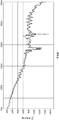
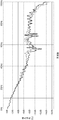
- insertion loss IL; Insertion Loss
- FIG. 1 is a cross-sectional view showing a schematic configuration of the communication cable 1.
- the communication cable 1 has a quad twisted body 10, an intervening string 20, a first shielding layer 30, a second shielding layer 40, and a sheath 50, and the outer periphery of the quad twisted body 10 is the first.
- the shielding layer 30, the second shielding layer 40, and the sheath 50 of 1 are wound and covered in this order.
- the quad twisted body 10 is composed of four core (four) insulated wires 12, and each insulated wire 12 is 7.0 mm or more and 17.5 mm or less, preferably 7.0 mm or more and 16 mm or less, more preferably. It has a structure in which it is twisted at a pitch of 7.0 mm or more and 14 mm or less, more preferably 10.0 mm or more and 14 mm or less.
- the lower limit value and the upper limit value of the twist pitch of the insulated wire 12 are set from the following viewpoints.
- the lower limit value is assumed from the viewpoint of whether or not stable production can suppress inward skew, and the lower limit value is practically 7.0 mm, preferably 10.0 mm.
- the twisted pitch of the insulated wire 12 becomes shorter, the twisted pair becomes excessively dense, and the twisted balance between the insulated wires 12 becomes unstable. As a result, there is a difference in physical length between the insulated wires 12 (the length varies), and it becomes difficult to suppress the inward skew.
- the twist pitch of the insulated wire 12 is set narrow, the amount (length) of the insulated wire 12 used increases, which is disadvantageous in terms of manufacturing or cost, and the above lower limit is assumed from the viewpoint of manufacturing feasibility. NS.
- the first type core 10A and the second type core 10B are used as a pair, and the third type core 10C and the fourth type core 10D are used as a pair.
- the quad twisted body 10 may be composed of a pair of a type 1 core 10A and a type 2 core 10B (2 cores), or a type 5 core-a core after the type 6 core. Pairs may be added and configured.
- the insulated wire 12 is composed of a conductor 14 and an insulator 16, and has a structure in which the outer circumference of the conductor 14 is covered with the insulator 16.
- the conductor 14 has a structure in which a plurality of wires are twisted together, and each wire is made of a conductive metal material. Each wire is preferably annealed copper wire, and its outer periphery is covered with a plating layer (not shown) of any one of tin, nickel, and silver.
- the outer diameter of the conductor 14 is preferably 0.45 to 0.50 mm.
- the insulator 16 is formed by extruding an insulating resin from a die of an extruder.
- the insulating resin is preferably cross-linked polyethylene (XLPE) or polypropylene.
- the thickness of the insulator 16 is preferably 0.15 to 0.35 mm.
- the intervening string 20 is arranged at the center of the quad twisted body 10 (four insulated wires 12).
- the intervening string 20 is a linear member having a circular cross section, and is provided to keep the arrangement of the insulated electric wires 12 constant.
- the intervening string 20 is preferably high density polyethylene (HDPE).
- the intervening string 20 may be made of nylon, polypropylene, polyethylene terephthalate or the like.
- the diameter of the intervening string 20 is preferably 0.3 to 0.5 mm.
- the first shielding layer 30 is formed by laminating and winding a metal tape.
- the metal tape is a tape formed by laminating a metal foil and a resin tape, and is preferably formed by laminating an aluminum foil and a polyethylene terephthalate tape (PET tape).
- PET tape polyethylene terephthalate tape
- the metal foil is overlaid so as to be exposed on the outer periphery.
- the thickness of the metal tape is preferably 0.03 to 0.06 mm.
- the second shielding layer 40 is formed by horizontally winding a plurality of metal wires at a constant pitch or less.
- the second shielding layer 40 may be braided with a plurality of metal wires.
- Each metal wire is preferably a so-called tinned annealed copper wire (TA) in which the annealed copper wire is coated with a tin-plated layer.
- the outer diameter of the metal wire is preferably 2.9 to 3.1 mm.
- the sheath 50 is a so-called outer layer, and is formed by extruding a resin for a sheath from a die of an extruder.
- the sheath resin is preferably composed of polyvinyl chloride (PVC) or thermoplastic elastomer (TPE).
- the thickness of the sheath 50 is preferably 0.2 to 0.6 mm.
- a plurality of strands are twisted to form a conductor 14, an insulating resin is extruded and coated on the conductor 14, and an electron beam is irradiated to the conductor 14 to crosslink the conductor 14 to form an insulator 16 to manufacture an insulated electric wire 12.
- S1 the intervening string 20 made of high-density polyethylene arranged in the center
- the four insulated wires 12 are twisted together at a pitch of 17.5 mm or less (quad twist, S2).
- a metal tape is overlaid around the quad twisted body 10 to form a first shielding layer 30, and a plurality of metal wires are horizontally wound to form a second shielding layer 40 (S3).
- the sheath resin is extruded and coated on the second shielding layer 40 to form the sheath 50 (S4), and the communication cable 1 can be manufactured.
- the sheath resin may be extruded by a pipe method or a pressure method.
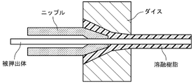
- the pipe method is a method in which a nipple is inserted from the opening of the die to the extrusion port, and the extruded body always passes through the center of the nipple when passing through the die, and the molten resin is extruded into a pipe shape (cylindrical shape) ( See FIG. 2B). According to the pipe method, even if the shape of the extruded body is irregular, the thickness of the sheath is constant and the extruded body is not crushed.
- the pressure method is a method in which a nipple is inserted from the opening of the die to the middle part, the extruded body passes through the center of the nipple when passing through the die, and then passes through the inside of the die, and the molten resin is pressed against the extruded body. It is extruded while being pushed (see FIG. 2C). According to the pressure method, the resin for the sheath easily adheres to the surface of the extruded body.
- the intervening string 20 since (i) the intervening string 20 is installed, the skew is 10 ps / m or less and the transmission state is stable. (Ii) Since each insulated wire 12 is twisted at a pitch of 17.5 mm or less, insertion loss (IL) does not drop (decrease) to 6 GHz, and signal attenuation in the high frequency band is suppressed. (See Examples 1 and 2 below). According to the communication cable 1, the intervening string 20 is installed and the twist pitch of each insulated wire 12 is set to a certain value or less. The communication cable is compatible with high frequency data transmission and is inside the cable. It is possible to provide a communication cable that can realize a simplification of the configuration.
- the second embodiment is different from the first embodiment in the following points.
- the quad twisted body 10 is covered with the push-wound 25
- the push-wound 25 is covered with the first shielding layer 30, and the quad twisted body 10 and the first shielding layer 30 are together.
- a push-wound 25 is formed between the two.
- the push-wound 25 is formed by laminating and winding tape-shaped polyethylene terephthalate (PET).
- PET polyethylene terephthalate
- the push-wound 25 may be made of a tape-shaped non-woven fabric.
- the thickness of the press winding 25 is preferably 0.02 to 0.5 mm.
- the distance between conductors between the pair lines of one pair of the first type core 10A and the second type core 10B (or one pair of the third type core 10C and the fourth type core 10D) is dc.
- the dc / ds value is 2 or less.
- the relationship that the dc / ds value is 2 or less is the pair line of the first type core 10A and the second type core 10B, or at least the pair line of the third type core 10C and the fourth type core 10D. It suffices to be filled in one pair of wires, preferably in both pairs of wires.
- the manufacturing method of the communication cable 2 will be described with reference to FIG. 3B.
- polyethylene terephthalate tape PET tape
- PET tape polyethylene terephthalate tape
- a metal tape is overlaid around the push-wound 25.
- the first shielding layer 30 is formed.
- the dc / ds value is set (designed) to 2 or less from the step S1 of manufacturing the insulated wire 12 to the step S3 of covering with the first shielding layer 30.
- a push-wound 25 is intentionally formed between the quad twisted pair 10 and the first shielding layer 30, and the first-class conductor 10A and the second-class conductor 10B are connected to each other.
- a physical distance is secured between the conductor 14 of the paired wire and the first shielding layer 30, and the dc / ds value is set to 2 or less.
- the electromagnetic coupling between the paired wire and the first shielding layer 30 can be weakened, and the signal attenuation in the high frequency band can be suppressed (see Example 3 below).
- the communication cable 1 or the communication cable 2 can be used for any purpose as long as it is used for communication, preferably used for in-vehicle use, and more preferably used for transmitting an image or video signal of an in-vehicle camera.
- the communication cable 1 or the communication cable 2 is used for in-vehicle use and it is desired to maintain the characteristics for a long period of time, it is better to adopt the pressure method rather than the pipe method for forming the sheath 50. This is because the relationship between the members in the sheath 50 is fixed (maintained).
- sample 1 First, seven tin-plated annealed copper wires having a diameter of 0.16 mm were twisted together to form a conductor having an outer diameter of 0.48 mm. Then, polyethylene was extruded and coated on the conductor, and the conductor was irradiated with an electron beam to crosslink the conductor to form an insulated wire having an outer diameter of 1.12 mm made of cross-linked polyethylene (XLPE). After that, four insulated wires are twisted at a pitch of 30 mm (quad twist) with a high-density polyethylene intervening string having a diameter of 0.45 mm arranged in the center to form a quad twisted body having an outer diameter of 2.70 mm. did.
- XLPE cross-linked polyethylene
- a metal tape in which an aluminum foil and a polyethylene terephthalate tape (PET tape) are bonded is prepared, and the metal tape is wound 1/4 on a quad twisted body to have an outer diameter of 2.82 mm.
- the first shielding layer of the above was formed.
- 84 tin-plated annealed copper wires (TA) having a diameter of 0.1 mm were prepared as the second shielding layer, and the tin-plated annealed copper wire was horizontally wound around the first shielding layer at a pitch of 32 mm or less, and the outer diameter was 3
- a second shielding layer of .02 mm was formed.
- polyvinyl chloride (PVC) was extruded and coated on the second shielding layer by a pipe method to prepare a communication cable having an outer diameter of 3.82 mm.
- Sample 11 In Sample 1 according to Example 1, four insulated wires were twisted (quad twisted) at a pitch of 14 mm, and this was designated as Sample 11. Specifically, seven tin-plated annealed copper wires having a diameter of 0.16 mm were twisted together to form a conductor having an outer diameter of 0.48 mm. Then, polyethylene was extruded and coated on the conductor, and the conductor was irradiated with an electron beam to crosslink the conductor to form an insulated wire having an outer diameter of 1.12 mm made of cross-linked polyethylene (XLPE).
- XLPE cross-linked polyethylene
- a metal tape in which an aluminum foil and a polyethylene terephthalate tape (PET tape) are bonded is prepared, and the metal tape is wound 1/4 on a quad twisted body to have an outer diameter of 2.82 mm.
- the first shielding layer of the above was formed.
- 84 tin-plated annealed copper wires (TA) having a diameter of 0.1 mm were prepared as the second shielding layer, and the tin-plated annealed copper wire was horizontally wound around the first shielding layer at a pitch of 32 mm or less, and the outer diameter was 3
- a second shielding layer of .02 mm was formed.
- polyvinyl chloride (PVC) was extruded and coated on the second shielding layer by a pipe method to prepare a communication cable having an outer diameter of 3.82 mm.
- Sample 1 Preparation of Sample
- four insulated wires were twisted (quad-twisted) at a pitch of 14 mm, and the quad-twisted body was covered with a push-wound to obtain Sample 21.
- seven tin-plated annealed copper wires having a diameter of 0.16 mm were twisted together to form a conductor having an outer diameter of 0.48 mm.
- polyethylene was extruded and coated on the conductor, and the conductor was irradiated with an electron beam to crosslink the conductor to form an insulated wire having an outer diameter of 0.88 mm made of cross-linked polyethylene (XLPE).
- XLPE cross-linked polyethylene
- PET tape polyethylene terephthalate tape
- PET tape polyethylene terephthalate tape
- the PET tape was wound in half on the quad twisted body to form a push-winding having an outer diameter of 2.69 mm.
- a metal tape in which an aluminum foil and a polyethylene terephthalate tape (PET tape) are bonded is prepared, and the metal tape is wound in 1/4 layer with respect to the push winding, and the outer diameter is 2.81 mm.
- a first shielding layer was formed.
- tin-plated annealed copper wires having a diameter of 0.1 mm were prepared as the second shielding layer, and the tin-plated annealed copper wire was horizontally wound around the first shielding layer at a pitch of 32 mm or less, and the outer diameter was 3 A second shielding layer of 0.01 mm was formed.
- polyvinyl chloride PVC was extruded and coated on the second shielding layer by a pipe method to prepare a communication cable having an outer diameter of 3.81 mm.
- ds (insulated wire outer diameter 1.12 mm-conductor outer diameter 0.48 mm)
- x 1/2 0.32 mm
- the present invention relates to a communication cable and a method for manufacturing the same, and is particularly useful for providing a communication cable that is compatible with high-frequency data transmission and that can realize a simplification of the internal configuration of the cable.
- Communication cable 2 Communication cable 10 Quad twisted body 10A to 10D 1st to 4th class core 12 Insulated electric wire 14 Conductor 16 Insulator 20 Intervening string 25 Push winding 30 1st shielding layer 40 2nd shielding layer 50 sheath
Landscapes
- Engineering & Computer Science (AREA)
- Manufacturing & Machinery (AREA)
- Physics & Mathematics (AREA)
- Electromagnetism (AREA)
- Communication Cables (AREA)
- Processes Specially Adapted For Manufacturing Cables (AREA)
- Insulated Conductors (AREA)
Priority Applications (3)
| Application Number | Priority Date | Filing Date | Title |
|---|---|---|---|
| CN202411680645.4A CN119694655A (zh) | 2020-01-24 | 2021-01-22 | 通信电缆及其制造方法 |
| CN202180010702.6A CN115023772A (zh) | 2020-01-24 | 2021-01-22 | 通信电缆及其制造方法 |
| JP2021572807A JP7111915B2 (ja) | 2020-01-24 | 2021-01-22 | 通信ケーブルおよびその製造方法 |
Applications Claiming Priority (2)
| Application Number | Priority Date | Filing Date | Title |
|---|---|---|---|
| JP2020009591 | 2020-01-24 | ||
| JP2020-009591 | 2020-01-24 |
Publications (1)
| Publication Number | Publication Date |
|---|---|
| WO2021149787A1 true WO2021149787A1 (ja) | 2021-07-29 |
Family
ID=76992482
Family Applications (1)
| Application Number | Title | Priority Date | Filing Date |
|---|---|---|---|
| PCT/JP2021/002157 Ceased WO2021149787A1 (ja) | 2020-01-24 | 2021-01-22 | 通信ケーブルおよびその製造方法 |
Country Status (3)
| Country | Link |
|---|---|
| JP (1) | JP7111915B2 (https=) |
| CN (2) | CN115023772A (https=) |
| WO (1) | WO2021149787A1 (https=) |
Cited By (1)
| Publication number | Priority date | Publication date | Assignee | Title |
|---|---|---|---|---|
| JP2025503684A (ja) * | 2022-02-10 | 2025-02-04 | エルエス ケーブル アンド システム リミテッド. | 車両イーサネットケーブル |
Citations (4)
| Publication number | Priority date | Publication date | Assignee | Title |
|---|---|---|---|---|
| JPH11144532A (ja) * | 1997-11-11 | 1999-05-28 | Furukawa Electric Co Ltd:The | 電気通信ケーブル |
| JP2001028208A (ja) * | 1999-07-14 | 2001-01-30 | Furukawa Electric Co Ltd:The | 通信ケーブル |
| JP2001093356A (ja) * | 1999-09-27 | 2001-04-06 | Sumitomo Wiring Syst Ltd | ツイストペアケーブル |
| JP2017033739A (ja) * | 2015-07-31 | 2017-02-09 | 日立金属株式会社 | ジャンパ線 |
Family Cites Families (4)
| Publication number | Priority date | Publication date | Assignee | Title |
|---|---|---|---|---|
| JP2006019080A (ja) * | 2004-06-30 | 2006-01-19 | Hitachi Cable Ltd | 差動信号伝送ケーブル |
| CN105551677B (zh) * | 2016-02-18 | 2016-11-30 | 江苏东强股份有限公司 | 特高频数字通信电缆及其制备方法 |
| CN205451903U (zh) * | 2016-02-18 | 2016-08-10 | 江苏东强股份有限公司 | 特高频数字通信电缆 |
| JP6876861B1 (ja) * | 2020-11-18 | 2021-05-26 | 株式会社デルタプラス | 複合電線及び該複合電線の製造方法 |
-
2021
- 2021-01-22 JP JP2021572807A patent/JP7111915B2/ja active Active
- 2021-01-22 CN CN202180010702.6A patent/CN115023772A/zh active Pending
- 2021-01-22 CN CN202411680645.4A patent/CN119694655A/zh active Pending
- 2021-01-22 WO PCT/JP2021/002157 patent/WO2021149787A1/ja not_active Ceased
Patent Citations (4)
| Publication number | Priority date | Publication date | Assignee | Title |
|---|---|---|---|---|
| JPH11144532A (ja) * | 1997-11-11 | 1999-05-28 | Furukawa Electric Co Ltd:The | 電気通信ケーブル |
| JP2001028208A (ja) * | 1999-07-14 | 2001-01-30 | Furukawa Electric Co Ltd:The | 通信ケーブル |
| JP2001093356A (ja) * | 1999-09-27 | 2001-04-06 | Sumitomo Wiring Syst Ltd | ツイストペアケーブル |
| JP2017033739A (ja) * | 2015-07-31 | 2017-02-09 | 日立金属株式会社 | ジャンパ線 |
Cited By (4)
| Publication number | Priority date | Publication date | Assignee | Title |
|---|---|---|---|---|
| JP2025503684A (ja) * | 2022-02-10 | 2025-02-04 | エルエス ケーブル アンド システム リミテッド. | 車両イーサネットケーブル |
| US20250095881A1 (en) * | 2022-02-10 | 2025-03-20 | Ls Cable & System Ltd. | Ethernet cable for vehicle |
| EP4478383A4 (en) * | 2022-02-10 | 2025-10-01 | Ls Cable & System Ltd | VEHICLE ETHERNET CABLE |
| JP7789936B2 (ja) | 2022-02-10 | 2025-12-22 | エルエス ケーブル アンド システム リミテッド. | 車両イーサネットケーブル |
Also Published As
| Publication number | Publication date |
|---|---|
| CN115023772A (zh) | 2022-09-06 |
| CN119694655A (zh) | 2025-03-25 |
| JPWO2021149787A1 (https=) | 2021-07-29 |
| JP7111915B2 (ja) | 2022-08-02 |
Similar Documents
| Publication | Publication Date | Title |
|---|---|---|
| US8859902B2 (en) | Multi-core cable | |
| US7358436B2 (en) | Dual-insulated, fixed together pair of conductors | |
| US20180301247A1 (en) | Parallel pair cable | |
| CN106067347B (zh) | 多芯电缆 | |
| KR20110127664A (ko) | 고속 차동 케이블 | |
| CN1890761A (zh) | 有顺捻缆芯断面的数据电缆 | |
| CN101809683A (zh) | 同轴电缆及多芯同轴电缆 | |
| TWM497332U (zh) | 多芯纜線 | |
| US11087904B2 (en) | Multicore cable | |
| US20180268965A1 (en) | Data cable for high speed data transmissions and method of manufacturing the data cable | |
| JP2026067961A (ja) | 通信ケーブル | |
| JP2012146409A (ja) | 多心信号ケーブルとその製造方法 | |
| JP5464080B2 (ja) | 同軸ケーブルおよび多心同軸ケーブル | |
| JP7111915B2 (ja) | 通信ケーブルおよびその製造方法 | |
| KR20220164689A (ko) | 동축 케이블 | |
| WO2014035927A1 (en) | S-shield twisted pair cable design for multi-ghz performance | |
| JP2019061767A (ja) | 差動伝送ケーブル及びワイヤーハーネス | |
| WO2022138900A1 (ja) | 通信ケーブルおよびその製造方法 | |
| CN117672614A (zh) | 二芯绞合屏蔽电缆及线束 | |
| JP2007280762A (ja) | ノンハロゲン同軸ケーブル及びこれを用いた多芯ケーブル | |
| JP7474590B2 (ja) | 多芯通信ケーブル | |
| WO2024248038A1 (ja) | 通信ケーブルおよびその製造方法 | |
| JP7622096B2 (ja) | 通信ケーブルおよびその製造方法 | |
| US20220028582A1 (en) | High-frequency coaxial cable | |
| WO2022138898A1 (ja) | 通信ケーブルおよびその製造方法 |
Legal Events
| Date | Code | Title | Description |
|---|---|---|---|
| 121 | Ep: the epo has been informed by wipo that ep was designated in this application |
Ref document number: 21743660 Country of ref document: EP Kind code of ref document: A1 |
|
| ENP | Entry into the national phase |
Ref document number: 2021572807 Country of ref document: JP Kind code of ref document: A |
|
| NENP | Non-entry into the national phase |
Ref country code: DE |
|
| 122 | Ep: pct application non-entry in european phase |
Ref document number: 21743660 Country of ref document: EP Kind code of ref document: A1 |