WO2021149597A1 - 制御装置、制御システム及び制御装置の機能又は動作の決定方法 - Google Patents
制御装置、制御システム及び制御装置の機能又は動作の決定方法 Download PDFInfo
- Publication number
- WO2021149597A1 WO2021149597A1 PCT/JP2021/001146 JP2021001146W WO2021149597A1 WO 2021149597 A1 WO2021149597 A1 WO 2021149597A1 JP 2021001146 W JP2021001146 W JP 2021001146W WO 2021149597 A1 WO2021149597 A1 WO 2021149597A1
- Authority
- WO
- WIPO (PCT)
- Prior art keywords
- control device
- related information
- data identifier
- control
- specific child
- Prior art date
- Legal status (The legal status is an assumption and is not a legal conclusion. Google has not performed a legal analysis and makes no representation as to the accuracy of the status listed.)
- Ceased
Links
Images


Classifications
-
- G—PHYSICS
- G05—CONTROLLING; REGULATING
- G05B—CONTROL OR REGULATING SYSTEMS IN GENERAL; FUNCTIONAL ELEMENTS OF SUCH SYSTEMS; MONITORING OR TESTING ARRANGEMENTS FOR SUCH SYSTEMS OR ELEMENTS
- G05B15/00—Systems controlled by a computer
- G05B15/02—Systems controlled by a computer electric
-
- G—PHYSICS
- G05—CONTROLLING; REGULATING
- G05B—CONTROL OR REGULATING SYSTEMS IN GENERAL; FUNCTIONAL ELEMENTS OF SUCH SYSTEMS; MONITORING OR TESTING ARRANGEMENTS FOR SUCH SYSTEMS OR ELEMENTS
- G05B19/00—Program-control systems
- G05B19/02—Program-control systems electric
- G05B19/04—Program control other than numerical control, i.e. in sequence controllers or logic controllers
- G05B19/042—Program control other than numerical control, i.e. in sequence controllers or logic controllers using digital processors
- G05B19/0426—Programming the control sequence
-
- G—PHYSICS
- G06—COMPUTING OR CALCULATING; COUNTING
- G06F—ELECTRIC DIGITAL DATA PROCESSING
- G06F13/00—Interconnection of, or transfer of information or other signals between, memories, input/output devices or central processing units
Definitions
- the present disclosure relates to a control device, a control system, and a method for determining a function or operation of the control device.
- ECUs Electronic Control Units
- the ECU is equipped with a CPU, a memory, an input / output interface, and the like, and transmits / receives information to and from each other through an in-vehicle LAN such as CAN or Ethernet (registered trademark).
- Patent Document 1 discloses a vehicle system in which a plurality of vehicle modules modularized according to the assembly structure of the vehicle are provided, and each vehicle module is provided with a vehicle module control unit (ECU).
- ECU vehicle module control unit
- the control device of the present disclosure communicates with a storage unit that stores related information in which a specific child that identifies a function or operation of the control device and a data identifier that identifies a data source device are associated with each of a plurality of specific children.
- a receiving unit that receives a data identifier from a source device via a line and a control unit are provided, and the control unit determines its own specific child based on the data identifier received by the receiving unit and the related information. ..
- the control system of the present disclosure includes a plurality of control devices having different functions or operations, and a central control device connected to the plurality of control devices via a communication line.
- the method for determining the function or operation of the control device of the present disclosure provides related information in which a specific child that identifies the function or operation of the control device and a data identifier that identifies the data source device are associated with each of a plurality of specific children. It is stored in the storage unit, a data identifier is received from the source device via the communication line, and a specific child is determined based on the received data identifier and related information.
- Patent Document 1 [Problems to be Solved by the present Disclosure
- the ECUs of Patent Document 1 are arranged according to the assembly structure of the vehicle, and each ECU has a different function and performs a different operation. Therefore, it is necessary to manufacture each ECU individually, which increases the manufacturing cost.
- the control device of the present embodiment has a storage unit that stores related information in which a specific child that identifies a function or operation of the control device and a data identifier that identifies a data source device are associated with each of a plurality of specific children.
- a receiving unit that receives a data identifier from a source device via a communication line and a control unit are provided, and the control unit determines its own specific child based on the data identifier received by the receiving unit and the related information. decide.
- the control system of the present embodiment includes a plurality of control devices having different functions or operations, and a central control device connected to the plurality of control devices via a communication line.
- the specific child that identifies the function or operation of the control device and the data identifier that identifies the data source device are associated with each of a plurality of specific children.
- Information is stored in the storage unit, a data identifier is received from the source device via the communication line, and a specific child is determined based on the received data identifier and related information.
- the storage unit stores related information in which a specific child that identifies the function or operation of the control device and a data identifier that identifies the data source device are associated with each of a plurality of specific children.
- the same related information is stored in the storage unit of each of the plurality of control devices mounted on the vehicle. For example, suppose that a vehicle is equipped with four control devices, the function or operation of the control device is represented by A, B, C, D, and the specific element that identifies the function or operation A, B, C, D is AAA. , BBB, CCC, DDD.
- the data identifiers of the source devices with which the control device having the function or operation A performs data communication are represented by # 100 and # 150, and similarly, the data identifiers corresponding to the control device having the function or operation B are represented by # 170 and # 170. It is assumed that the data identifier corresponding to the control device whose function or operation is C is represented by # 250 and # 300, and the data identifier corresponding to the control device whose function or operation is D is represented by # 350.
- the receiving unit receives the data identifier from the source device via the communication line.
- the receiving unit can receive the data identifier by starting the transmission of data from each source device at the manufacturing stage or the assembly stage in which the common control device is incorporated in the vehicle.
- the control unit determines its own specific child based on the data identifier and related information received by the reception unit. For example, when a control device receives data whose data identifiers are # 100 and # 150, its function or operation is specified by the specifier AAA based on the related information stored in the storage unit. It can be determined that the operation A is performed. The same applies to other control devices.
- a common control device can be incorporated into a vehicle, and the function or operation of each control device can be determined at the manufacturing stage or the assembly stage.
- a common control device can be manufactured, and the function or operation of each control device can be determined at the manufacturing stage or assembly stage of the vehicle, so that it is not necessary to individually manufacture control devices having different functions or operations in advance. , Manufacturing cost can be reduced.
- control unit refers to the related information stored in the storage unit based on the data identifier received by the reception unit, and is associated with a data identifier that matches the received data identifier. Determine a specific child as its own specific child.
- the control unit can refer to the related information stored in the storage unit based on the data identifier received by the reception unit, and determine the specific child associated with the data identifier that matches the received data identifier as its own specific child. can.
- control unit outputs the determined specific child to the program providing device, and acquires a program for realizing the function or operation specified by the specific child from the program providing device. ..
- the control unit outputs the determined specific child to the program providing device.
- the program providing device can change the common control device into a control device for each function or operation by introducing a program for each function or operation into the common control device, for example.
- the control unit acquires a program for realizing a function or operation specified by a specific child from the program providing device.
- the control device can realize the function or operation specified by the specific child by introducing (installing) the acquired program. That is, in the manufacturing stage or the assembly stage of the vehicle, the common control device can be changed to a control device for each function or operation.
- acquiring the program also includes acquiring parameters (for example, a config file) read by the program.
- control unit executes processing based on the acquired program.
- the control unit executes processing based on the acquired program.
- each of the control devices mounted on the vehicle can execute not only a common function or operation but also a unique function or operation.
- control unit when the data identifier received by the receiving unit is not included in the related information, the control unit acquires the related information from the related information providing device and stores it in the storage unit. Update the related information with the acquired related information.
- the control unit acquires the related information from the related information providing device when the data identifier received by the receiving unit is not included in the related information.
- the related information providing device can hold the latest related information.
- the control unit updates the related information stored in the storage unit with the related information acquired by the second acquisition unit.
- the information of the newly added source device is added to the related information stored in the storage unit. It may not be remembered. In such a case, the related information can be updated to the latest information by updating the related information.
- the control device of the present embodiment includes a recording unit that records the data identifier as an error log when the data identifier received by the receiving unit is not included in the related information stored in the storage unit.
- the recording unit records the data identifier as an error log when the data identifier received by the receiving unit is not included in the related information stored in the storage unit. If the received data identifier is not included in the related information stored in the storage unit, there is a high possibility that data garbled has occurred in the data communication. Various factors such as defective transmission device and poor connection of communication line connector etc. can be considered as causes of data garbled. Therefore, by recording the error log, the cause of the defect can be identified and necessary countermeasures can be taken.
- control unit when the data identifier received by the receiving unit is not included in the related information stored in the storage unit, the control unit notifies the central control unit of the undecidedness of the specific child. ..
- the control unit If the data identifier received by the receiving unit is not included in the related information stored in the storage unit, the control unit notifies the central control device of the undecided specific child.
- the central control device can be a higher-level control device that manages each control device. Thereby, the central control device can determine whether or not each control device has been able to determine the function or operation.
- control unit notifies the central control device of the determined specific child.
- the control unit notifies the central control device of the determined specific child. Thereby, the central control device can determine whether or not each control device has been able to determine the function or operation.
- the central control device includes a storage unit that stores information on whether or not a specific element of each of the plurality of control devices is determined, and a control unit.
- a storage unit that stores information on whether or not a specific element of each of the plurality of control devices is determined
- a control unit When one control device notifies itself of the undecided specific child, the specific child of the one control device is determined based on the information stored in the storage unit, and the determined specific child is controlled by the one. Notify the device.
- the central control unit includes a storage unit that stores information as to whether or not a specific child of each of the plurality of control devices has been determined, and the control unit notifies itself that the specific child has not been determined by one control unit. , The specific child of the one control device is determined based on the information stored in the storage unit, and the determined specific child is notified to the one control device.
- the function or operation of the control device is represented by A, B, C, D
- the specific element that identifies the function or operation A, B, C, D is AAA. , BBB, CCC, DDD.
- three control devices notify that the specific child is BBB, CCC, and DDD, respectively, and the remaining one control device notifies that the specific child is undecided.
- the central control device determines that the specific child of the control device whose specific child is undecided is AAA (other than BBB, CCC and DDD), and notifies the control device.
- the central control device can determine the specific child.
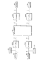
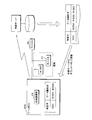
- FIG. 1 is a schematic diagram showing an example of the configuration of the control system of the present embodiment.
- the control system includes a central ECU 10 as a central control device and zone ECUs 20A, 20B, 20C, and 20D as control devices.
- the zone ECUs 20A, 20B, 20C, and 20D are collectively referred to as the zone ECU 20.
- the central ECU 10 can be a higher-level ECU that manages each zone ECU 20. In the figure, the configuration is provided with four zone ECUs, but a plurality of zone ECUs may be provided, and the number is not limited to four.
- the central ECU 10 and the zone ECUs 20A, 20B, 20C, and 20D are connected by a communication line 2.
- the communication line 2 can be, for example, Ethernet (registered trademark), but is not limited thereto.
- the zone ECUs 20A, 20B, 20C, and 20D perform common functions or operations, and also perform different functions or operations according to the arrangement of controlled objects in each vehicle (for example, front, rear, left, and right of the vehicle).
- the zone ECU 20A can communicate with the devices 31 and 32 via the communication line 1
- the zone ECU 20B can communicate with the devices 33 and 34 via the communication line 1
- the zone ECU 20C can communicate with the devices 33 and 34 via the communication line 1.
- It can communicate with the device 35 via the communication line 1
- the zone ECU 20D can communicate with the device 36 via the communication line 1.
- the communication line 1 can be, for example, CAN (Controller Area Network), but is not limited to this.
- Devices 31 to 36 include, for example, actuators, sensors, switches, ECUs (Electronic Control Units), and the like.
- the zone ECUs 20A, 20B, 20C, and 20D can be said to be ECUs that integrate various functions.
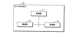
- FIG. 2 is a block diagram showing an example of the configuration of the central ECU 10.
- the central ECU 10 includes a control unit 11, a communication unit 12, and a storage unit 13.
- the control unit 11 can be composed of a CPU, ROM, RAM, etc., and controls the entire central ECU 10.
- the communication unit 12 has a function of communicating with each of the zone ECUs 20A, 20B, 20C, and 20D using the communication protocol defined by the communication line 2.
- the storage unit 13 can be configured by, for example, a semiconductor memory or the like, and can store information received from each of the zone ECUs 20A, 20B, 20C, and 20D. Further, the storage unit 13 can store information to be transmitted to each of the zone ECUs 20A, 20B, 20C, and 20D. The storage unit 13 can store information on whether or not the specific elements of the zone ECUs 20A, 20B, 20C, and 20D have been determined. The specifier specifies the function or operation of each zone ECU 20A, 20B, 20C, 20D.
- the control unit 11 determines the specific child of the one zone ECU based on the information stored in the storage unit 13. be able to.
- the fact that the specific child is undecided can also mean that the mounting position is unassigned. The details of the method for determining the specific child will be described later.
- the control unit 11 can notify the determined specific child to one zone ECU (the zone ECU that has notified that the specific child is undecided). Further, the control unit 11 can output a warning as an abnormality when there is a zone ECU in which the specific element is undecided.
- the warning output may be in the form of display or in the form of voice output.
- FIG. 3 is a block diagram showing an example of the configuration of the zone ECU 20.
- the zone ECU 20 includes a control unit 21, a communication unit 22, a wide area communication unit 23, a storage unit 24, and an error log recording unit 25.
- the control unit 21 can be composed of a CPU, ROM, RAM, etc., and controls the entire zone ECU 20.
- the communication unit 22 has a function of communicating with a device (any of 31 to 36) connected to the zone ECU using the communication protocol defined by the communication line 1.
- the communication unit 22 has a function as a reception unit, and can receive a data identifier from a device (source device) via the communication line 1.
- the data identifier identifies the device that is the source of the data. For example, when the communication protocol is CAN, CAN-ID can be used.
- the communication unit 22 has a function of communicating with the central ECU 10 by using the communication protocol defined by the communication line 2.
- the wide area communication unit 23 can send and receive data to and from an external server (related information providing device, program providing device) via the Internet, a telephone line, or the like.
- an external server related information providing device, program providing device
- the storage unit 24 can be configured by, for example, a semiconductor memory or the like, and can store related information. Details of the related information will be described later.
- the control unit 21 can determine the specific child of the zone ECU based on the data identifier received by the communication unit 22 and the related information stored in the storage unit 24. The details of the method for determining the specific child will be described later.
- the control unit 21 can update the related information stored in the storage unit 24 with the related information acquired from the external server.
- the error log recording unit 25 has a function as a recording unit, and when the data identifier received by the communication unit 22 is not included in the related information stored in the storage unit 24, the error log recording unit 25 may record the data identifier as an error log. can.
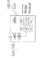
- FIG. 4 is a schematic diagram showing an example of related information.
- the related information is information in which a specific element that specifies the function or operation of the zone ECU and a data identifier that identifies a source device that transmits data to the zone ECU are associated with each of a plurality of specific elements. As shown in FIG. 4, the related information can be composed of each item of function or operation, specific child, data identifier, and source device.
- the same related information is stored in the storage unit 24 of each zone ECU mounted on the vehicle.
- different functions or operations of the four zone ECUs are represented by A, B, C, and D according to the mounting position in the vehicle, and the functions or actions A.
- B, C, and D are specified by AAA, BBB, CCC, and DDD.
- the zone ECU having the function or operation A receives the data identifier # 100 from the source device 32 and the data identifier # 150 from the source device 31. From the mounting position of the zone ECU and each source device in the vehicle, the function or operation (that is, the specific element) of the zone ECU can be associated with the device that transmits / receives data in advance. Similarly, it is assumed that the zone ECU having the function or operation B receives the data identifier # 170 from the source device 33 and the data identifier # 200 from the source device 34. It is assumed that the zone ECU having the function or operation C receives the data identifiers # 250 and # 300 from the source device 35, and the zone ECU having the function or operation D receives the data identifier # 350 from the source device 36. ..
- each zone ECU mounted on the vehicle is manufactured with the same part number, for example, and is standardized. That is, at the time of incorporating each zone ECU into the vehicle, it has not been determined which function or operation the zone ECU itself performs.
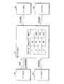
- FIG. 5 is a schematic diagram showing an example of a function or a method of determining the operation of the zone ECU 20.
- Each device is predetermined by incorporating the zone ECU and each device into the vehicle and starting the operation by turning on the power of the system, for example, in the state where each part is connected by a communication line (manufacturing stage or assembly stage). Data can be periodically transmitted to the zone ECU according to the procedure.
- the communication unit 22 receives the data identifier from the source device via the communication line 1.
- the communication unit 22 can receive the data identifier by starting the transmission of data from each source device in the manufacturing stage or the assembly stage in which the common control device is incorporated in the vehicle.
- the data identifiers are # 100 and # 150.
- the control unit 21 determines the specific child of the zone ECU 20 based on the data identifier received by the communication unit 22 and the related information stored in the storage unit 24.
- the specifier corresponding to the received data identifiers # 100 and # 150 is the specifier AAA
- the function or operation of the zone ECU 20 is the function or operation A. Can be done.
- the specific child can be determined in the same manner, and the function or operation can also be determined. In this way, the function or operation of each zone ECU can be automatically determined, and manual work by manufacturing personnel or the like is unnecessary.
- a common general-purpose zone ECU can be incorporated into a vehicle, and the function or operation of each zone ECU in the vehicle can be determined at the manufacturing stage or the assembly stage.
- a common general-purpose zone ECU can be manufactured, and the function or operation of each zone ECU can be determined at the manufacturing stage or the assembly stage of the vehicle. Therefore, ECUs having different functions and operations are individually manufactured in advance. There is no need, and the manufacturing cost can be reduced.
- the control unit 21 outputs the determined specific child to an external server as a program providing device via the wide area communication unit 23.
- the external server may change the common general-purpose zone ECU to a common general-purpose zone ECU by introducing a function or operation-specific program into the common general-purpose zone ECU, for example. can.
- the control unit 21 can acquire a program for realizing a function or operation specified by a specific child from an external server via the wide area communication unit 23.
- the zone ECU 20 can realize a function or operation specified by a specific child by introducing (installing) the acquired program. That is, at the vehicle manufacturing stage or assembly stage, the common general-purpose zone ECU 20 can be changed to a zone ECU 20 according to function or operation.
- acquiring the program also includes acquiring parameters (for example, a config file) read by the program of the zone ECU 20.
- the control unit 21 can execute processing based on the program acquired from the external server.
- each of the zone ECUs 20 mounted on the vehicle can execute not only a common function or operation but also a unique function or operation according to the mounting position of the vehicle, for example.
- the acquisition destination of the program is not limited to the external server.
- a program for realizing different functions or operations of each zone ECU may be stored in the central ECU 10 in advance, and the program may be acquired from the central ECU 10.
- the control unit 21 can notify the central ECU 10 of the determined specific child via the communication unit 22. Thereby, the central ECU 10 can determine whether or not each zone ECU 20 has been able to determine the function or operation.
- FIG. 6 is a schematic diagram showing an example of processing when the zone ECU 20 cannot determine the function or operation.
- the error log recording unit 25 can record the data identifier as an error log when the data identifier received by the communication unit 22 is not included in the related information stored in the storage unit 24.
- the communication unit 22 receives the data identifier # 110, but the specific child corresponding to the data identifier # 110 does not exist. It is also possible to record the source device of the data identifier in the error log. For example, in the example of FIG. 4, assuming that the data identifier # 100 is received and the data identifier # 110 is received instead of the data identifier # 150, the device 31 can be recorded in the error log.
- the received data identifier is not included in the related information stored in the storage unit 24, there is a high possibility that data garbled has occurred in the data communication.
- Various factors such as a defective device of the transmitting source and a poor connection of the connector of the communication line can be considered as the cause of the garbled data. Therefore, by recording the error log, the cause of the defect can be identified and necessary countermeasures can be taken.
- the control unit 21 can notify the central ECU 10 of the undecided specific child when the received data identifier is not included in the related information stored in the storage unit 24 via the communication unit 22. Thereby, the central ECU 10 can determine whether or not each zone ECU 20 has been able to determine the function or operation.
- FIG. 7 is a schematic diagram showing an example of a function or a method of determining the operation of the zone ECU 20 by the central ECU 10.
- the storage unit 13 of the central ECU 10 can store information on whether or not the specific element of each zone ECU 20 has been determined.
- the functions or operations of the zone ECU 20 are represented by A, B, C, and D, and the functions or operations A, B, C, and D are specified. It is assumed that the specific child is represented by AAA, BBB, CCC, and DDD.
- zone ECUs 20 notify that the specific child is BBB, CCC, and DDD, respectively, and the remaining one zone ECU 20 notifies that the specific child is undecided.
- the central ECU 10 determines that the specific child of the zone ECU 20 whose specific child is undecided is AAA (other than BBB, CCC and DDD), and notifies the zone ECU 20.
- AAA other than BBB, CCC and DDD
- FIG. 8 is a schematic diagram showing an example of how to update related information.
- the zone ECU 20C receives the data identifier # 160 which is not included in the related information (the association information between the specific child CCC and the data identifiers # 250 and # 300).
- the control unit 21 can acquire the latest related information from the external server as the related information providing device via the wide area communication unit 23.
- the control unit 21 updates the related information stored in the storage unit 24 with the related information acquired from the external server.
- the newly added source device is added to the related information stored in the storage unit 24.
- Information may not be stored.
- the related information can be updated to the latest information by updating the related information. If a data identifier that is not included in the related information is received even if it is updated, an abnormality may be notified.
- FIG. 9 is a flowchart showing an example of the processing procedure of the control system of the present embodiment.
- the central ECU 10 sets related information (S11).
- the related information can be set by the operator at the manufacturing stage or the assembling stage of the vehicle.
- the central ECU 10 transmits related information to each zone ECU 20 (S12).
- the zone ECU 20 receives and stores the related information (S31).
- the zone ECU 20 receives the data identifier from the device (source device) (S32), and determines whether or not the specific child of the zone ECU can be determined (S33).
- the zone ECU 20 downloads the program corresponding to the determined specific child (S34), notifies the determined specific child to the central ECU 10 (S35), and ends the process.
- the central ECU 10 performs the process of step S13 described later.
- the zone ECU 20 records an error log (S36), notifies the central ECU 10 that the specific child has not been determined (S37), and the central ECU 10 notifies the central ECU 10 that the specific child has not been determined (S37). Process.
- the central ECU 10 records the specific child as determined (S13), and performs the process of step S15 described later. Further, the central ECU 10 records the specific child as undecided (S14), and determines the presence or absence of the zone ECU 20 in which the specific child is undecided (S15). When there is a zone ECU 20 in which the specific child is undecided (YES in S15), the central ECU 10 determines the specific child of the zone ECU in which the specific child is undecided and notifies the zone ECU 20 (S16), and the zone ECU 20 will be described later. The process of step S38 is performed. When there is no zone ECU 20 in which the specific child is undetermined (NO in S15), the central ECU 10 ends the process.
- the zone ECU 20 determines whether or not there is a notification of the specific child from the central ECU 10 (S38), and if there is no notification (NO in S38), the process of step S38 is continued. When notified (YES in S38), the zone ECU 20 determines a specific child (S39) and ends the process.
- each zone ECU can also have a function as a power distributor.
- power from the battery can be supplied to the device via the zone ECU.
Landscapes
- Engineering & Computer Science (AREA)
- Physics & Mathematics (AREA)
- General Physics & Mathematics (AREA)
- Theoretical Computer Science (AREA)
- General Engineering & Computer Science (AREA)
- Automation & Control Theory (AREA)
- Stored Programmes (AREA)
- Information Transfer Between Computers (AREA)
- Small-Scale Networks (AREA)
Priority Applications (2)
| Application Number | Priority Date | Filing Date | Title |
|---|---|---|---|
| US17/759,253 US20230052810A1 (en) | 2020-01-24 | 2021-01-15 | Control apparatus, control system, and method for determining function or operation of control apparatus |
| CN202180008069.7A CN114930308A (zh) | 2020-01-24 | 2021-01-15 | 控制装置、控制系统及控制装置的功能或动作的决定方法 |
Applications Claiming Priority (2)
| Application Number | Priority Date | Filing Date | Title |
|---|---|---|---|
| JP2020010238A JP7375573B2 (ja) | 2020-01-24 | 2020-01-24 | 制御装置、制御システム及び制御装置の機能又は動作の決定方法 |
| JP2020-010238 | 2020-01-24 |
Publications (1)
| Publication Number | Publication Date |
|---|---|
| WO2021149597A1 true WO2021149597A1 (ja) | 2021-07-29 |
Family
ID=76992744
Family Applications (1)
| Application Number | Title | Priority Date | Filing Date |
|---|---|---|---|
| PCT/JP2021/001146 Ceased WO2021149597A1 (ja) | 2020-01-24 | 2021-01-15 | 制御装置、制御システム及び制御装置の機能又は動作の決定方法 |
Country Status (4)
| Country | Link |
|---|---|
| US (1) | US20230052810A1 (https=) |
| JP (2) | JP7375573B2 (https=) |
| CN (1) | CN114930308A (https=) |
| WO (1) | WO2021149597A1 (https=) |
Families Citing this family (1)
| Publication number | Priority date | Publication date | Assignee | Title |
|---|---|---|---|---|
| JP7307116B2 (ja) * | 2021-04-07 | 2023-07-11 | 矢崎総業株式会社 | 車載ソフトウェア更新方法および車載システム |
Citations (2)
| Publication number | Priority date | Publication date | Assignee | Title |
|---|---|---|---|---|
| JP2007109007A (ja) * | 2005-10-13 | 2007-04-26 | Matsushita Electric Ind Co Ltd | 携帯端末装置 |
| JP2019034684A (ja) * | 2017-08-21 | 2019-03-07 | 住友電気工業株式会社 | 車載機器制御システム、管理サーバ、車載通信装置、コンピュータプログラム、および車載機器制御方法 |
Family Cites Families (12)
| Publication number | Priority date | Publication date | Assignee | Title |
|---|---|---|---|---|
| JP5345500B2 (ja) * | 2009-10-16 | 2013-11-20 | 日本電信電話株式会社 | 転送制御方法、転送制御装置、転送制御システムおよび転送制御プログラム |
| JP5741496B2 (ja) * | 2012-03-14 | 2015-07-01 | 株式会社オートネットワーク技術研究所 | 車載通信システム |
| JP6170844B2 (ja) * | 2014-02-14 | 2017-07-26 | 株式会社Nttドコモ | 認証情報管理システム |
| WO2015133181A1 (ja) * | 2014-03-04 | 2015-09-11 | 日本電気株式会社 | 通信装置、通信制御方法および記録媒体 |
| JP5665207B1 (ja) * | 2014-03-21 | 2015-02-04 | 株式会社イッカツ | 情報入力システム、情報入力方法、及び情報入力プログラム |
| US9552248B2 (en) * | 2014-12-11 | 2017-01-24 | Pure Storage, Inc. | Cloud alert to replica |
| EP3598311A4 (en) * | 2017-03-13 | 2020-02-26 | Mitsubishi Electric Corporation | Communication device, server, communication system, communication method, and program |
| JP2020524427A (ja) * | 2017-06-20 | 2020-08-13 | 707 リミテッド | デジタル文書の存在を証明する方法、そのためのシステム、及びタグチェーンブロックチェーンシステム |
| US10204241B2 (en) * | 2017-06-30 | 2019-02-12 | Microsoft Technology Licensing, Llc | Theft and tamper resistant data protection |
| JP6992318B2 (ja) * | 2017-08-10 | 2022-01-13 | 株式会社デンソー | 電子制御装置 |
| JP6868582B2 (ja) * | 2018-02-27 | 2021-05-12 | Kddi株式会社 | 中継装置、通信システム及び通信履歴記憶方法 |
| US10795719B2 (en) * | 2018-06-29 | 2020-10-06 | Alegeus Technologies, Llc | Dynamic state-driven centralized processing |
-
2020
- 2020-01-24 JP JP2020010238A patent/JP7375573B2/ja active Active
-
2021
- 2021-01-15 CN CN202180008069.7A patent/CN114930308A/zh active Pending
- 2021-01-15 US US17/759,253 patent/US20230052810A1/en active Pending
- 2021-01-15 WO PCT/JP2021/001146 patent/WO2021149597A1/ja not_active Ceased
-
2023
- 2023-10-18 JP JP2023179604A patent/JP7582423B2/ja active Active
Patent Citations (2)
| Publication number | Priority date | Publication date | Assignee | Title |
|---|---|---|---|---|
| JP2007109007A (ja) * | 2005-10-13 | 2007-04-26 | Matsushita Electric Ind Co Ltd | 携帯端末装置 |
| JP2019034684A (ja) * | 2017-08-21 | 2019-03-07 | 住友電気工業株式会社 | 車載機器制御システム、管理サーバ、車載通信装置、コンピュータプログラム、および車載機器制御方法 |
Also Published As
| Publication number | Publication date |
|---|---|
| CN114930308A (zh) | 2022-08-19 |
| JP2023182795A (ja) | 2023-12-26 |
| JP7582423B2 (ja) | 2024-11-13 |
| JP7375573B2 (ja) | 2023-11-08 |
| JP2021117694A (ja) | 2021-08-10 |
| US20230052810A1 (en) | 2023-02-16 |
Similar Documents
| Publication | Publication Date | Title |
|---|---|---|
| JP4416649B2 (ja) | 車両に係るテレマチックサービスのための方法及び装置 | |
| US11713007B2 (en) | Configurable management system for a vehicle and method of use | |
| US6907331B2 (en) | Vehicle control system and apparatus therefor | |
| US7793017B2 (en) | Connection module for sensors | |
| JP4593626B2 (ja) | 車載データベースシステム | |
| CN100374962C (zh) | 具有多个节点的网络以及这种类型网络的节点 | |
| WO2014148003A1 (ja) | 車載電子制御装置のプログラム書換システム及び車載中継装置 | |
| KR101886076B1 (ko) | 네트워크 제어기 관리 시스템 및 방법 | |
| JP7582423B2 (ja) | 制御装置、制御システム及び制御装置の機能又は動作の決定方法 | |
| US11301236B2 (en) | Updating components of a modular system | |
| US20120210030A1 (en) | Automation system and method for operating an automation system | |
| CN113728279B (zh) | 用于改变自动化系统的控制软件的方法 | |
| US20230418587A1 (en) | Vehicle control device, vehicle system and update system | |
| US7860110B2 (en) | Auto-addressing system and method | |
| JP7781007B2 (ja) | 情報処理方法、通信システムおよび情報処理プログラム | |
| WO2024219242A1 (ja) | 冗長系ecu、プログラム、及び情報処理方法 | |
| EP4002812B1 (en) | Communication system with accessory device configuration | |
| JP7828232B2 (ja) | 車載装置、情報処理方法および情報処理プログラム | |
| JP7419851B2 (ja) | 照明制御システム | |
| CN116430803A (zh) | 用于将机器连接到生产线的系统 | |
| CN119697027A (zh) | 一种诊断服务的升级方法、装置及存储介质 | |
| CN119071819A (zh) | 车辆的ota的配置方法和配置系统 | |
| JP2006035356A (ja) | 設備制御装置 | |
| JPH08272702A (ja) | 通信履歴収集機能付きコントローラ |
Legal Events
| Date | Code | Title | Description |
|---|---|---|---|
| 121 | Ep: the epo has been informed by wipo that ep was designated in this application |
Ref document number: 21743944 Country of ref document: EP Kind code of ref document: A1 |
|
| NENP | Non-entry into the national phase |
Ref country code: DE |
|
| 122 | Ep: pct application non-entry in european phase |
Ref document number: 21743944 Country of ref document: EP Kind code of ref document: A1 |