WO2021149597A1 - Control apparatus, control system, and method for determining function or operation of control apparatus - Google Patents
Control apparatus, control system, and method for determining function or operation of control apparatus Download PDFInfo
- Publication number
- WO2021149597A1 WO2021149597A1 PCT/JP2021/001146 JP2021001146W WO2021149597A1 WO 2021149597 A1 WO2021149597 A1 WO 2021149597A1 JP 2021001146 W JP2021001146 W JP 2021001146W WO 2021149597 A1 WO2021149597 A1 WO 2021149597A1
- Authority
- WO
- WIPO (PCT)
- Prior art keywords
- control device
- related information
- data identifier
- control
- specific child
- Prior art date
Links
Images


Classifications
-
- G—PHYSICS
- G05—CONTROLLING; REGULATING
- G05B—CONTROL OR REGULATING SYSTEMS IN GENERAL; FUNCTIONAL ELEMENTS OF SUCH SYSTEMS; MONITORING OR TESTING ARRANGEMENTS FOR SUCH SYSTEMS OR ELEMENTS
- G05B15/00—Systems controlled by a computer
- G05B15/02—Systems controlled by a computer electric
-
- G—PHYSICS
- G05—CONTROLLING; REGULATING
- G05B—CONTROL OR REGULATING SYSTEMS IN GENERAL; FUNCTIONAL ELEMENTS OF SUCH SYSTEMS; MONITORING OR TESTING ARRANGEMENTS FOR SUCH SYSTEMS OR ELEMENTS
- G05B19/00—Programme-control systems
- G05B19/02—Programme-control systems electric
- G05B19/04—Programme control other than numerical control, i.e. in sequence controllers or logic controllers
- G05B19/042—Programme control other than numerical control, i.e. in sequence controllers or logic controllers using digital processors
- G05B19/0426—Programming the control sequence
-
- G—PHYSICS
- G06—COMPUTING; CALCULATING OR COUNTING
- G06F—ELECTRIC DIGITAL DATA PROCESSING
- G06F13/00—Interconnection of, or transfer of information or other signals between, memories, input/output devices or central processing units
Landscapes
- Engineering & Computer Science (AREA)
- Physics & Mathematics (AREA)
- General Physics & Mathematics (AREA)
- General Engineering & Computer Science (AREA)
- Automation & Control Theory (AREA)
- Theoretical Computer Science (AREA)
- Stored Programmes (AREA)
- Information Transfer Between Computers (AREA)
- Small-Scale Networks (AREA)
Abstract
Provided are a control apparatus, a control system, and a method for determining the function or operation of the control apparatus, with which it is possible to reduce manufacturing costs. This control apparatus is provided with a storage unit for storing association information in which a specifier for specifying the function or operation of the control apparatus and a data identifier for identifying a data transmission source device are associated with one another for each of a plurality of said specifiers, a receiving unit for receiving the data identifier from the transmission source device by way of a communication line, and a control unit, wherein the control unit determines the specifiers of the control unit itself on the basis of the data identifier received by the receiving unit and the association information.
Description
本開示は、制御装置、制御システム及び制御装置の機能又は動作の決定方法に関する。
本出願は、2020年1月24日出願の日本出願第2020-010238号に基づく優先権を主張し、前記日本出願に記載された全ての記載内容を援用するものである。 The present disclosure relates to a control device, a control system, and a method for determining a function or operation of the control device.
This application claims priority based on Japanese Application No. 2020-01238 filed on January 24, 2020, and incorporates all the contents described in the Japanese application.
近年の電子技術の進展により、車両には、エンジン、バッテリ、ドア、ランプ、ワイパー、エアコンなど様々な車載部品を制御するためのECU(Electronic Control Unit:電子制御装置)が多数搭載されるようになった。ECUは、CPU、メモリ、入出力インタフェースなどを備え、CANやイーサネット(登録商標)などの車載LANを通じて相互に情報の送受信を行っている。
Due to recent advances in electronic technology, vehicles are now equipped with a large number of ECUs (Electronic Control Units) for controlling various in-vehicle parts such as engines, batteries, doors, lamps, wipers, and air conditioners. became. The ECU is equipped with a CPU, a memory, an input / output interface, and the like, and transmits / receives information to and from each other through an in-vehicle LAN such as CAN or Ethernet (registered trademark).
特許文献1には、車両の組立構造に応じてモジュール化された複数の車両モジュールを備え、各車両モジュールには、車両モジュール制御装置(ECU)が設けられた車両システムが開示されている。
Patent Document 1 discloses a vehicle system in which a plurality of vehicle modules modularized according to the assembly structure of the vehicle are provided, and each vehicle module is provided with a vehicle module control unit (ECU).
本開示の制御装置は、制御装置の機能又は動作を特定する特定子とデータの送信元デバイスを識別するデータ識別子とを、複数の特定子毎に関連付けた関連情報を記憶する記憶部と、通信線を介して送信元デバイスからデータ識別子を受信する受信部と、制御部とを備え、前記制御部は、前記受信部で受信したデータ識別子及び前記関連情報に基づいて自身の特定子を決定する。
The control device of the present disclosure communicates with a storage unit that stores related information in which a specific child that identifies a function or operation of the control device and a data identifier that identifies a data source device are associated with each of a plurality of specific children. A receiving unit that receives a data identifier from a source device via a line and a control unit are provided, and the control unit determines its own specific child based on the data identifier received by the receiving unit and the related information. ..
本開示の制御システムは、機能又は動作が異なる複数の制御装置と、通信線を介して前記複数の制御装置と接続された中央制御装置とを備える。
The control system of the present disclosure includes a plurality of control devices having different functions or operations, and a central control device connected to the plurality of control devices via a communication line.
本開示の制御装置の機能又は動作の決定方法は、制御装置の機能又は動作を特定する特定子とデータの送信元デバイスを識別するデータ識別子とを、複数の特定子毎に関連付けた関連情報を記憶部に記憶し、通信線を介して送信元デバイスからデータ識別子を受信し、受信されたデータ識別子及び関連情報に基づいて特定子を決定する。
The method for determining the function or operation of the control device of the present disclosure provides related information in which a specific child that identifies the function or operation of the control device and a data identifier that identifies the data source device are associated with each of a plurality of specific children. It is stored in the storage unit, a data identifier is received from the source device via the communication line, and a specific child is determined based on the received data identifier and related information.
[本開示が解決しようとする課題
特許文献1のECUは、車両の組立構造に応じて配置され、それぞれのECUが異なる機能を有し、また異なる動作を行う。このため、それぞれECUを個別に製造する必要があり製造コストが高くなる。 [Problems to be Solved by the present Disclosure The ECUs ofPatent Document 1 are arranged according to the assembly structure of the vehicle, and each ECU has a different function and performs a different operation. Therefore, it is necessary to manufacture each ECU individually, which increases the manufacturing cost.
特許文献1のECUは、車両の組立構造に応じて配置され、それぞれのECUが異なる機能を有し、また異なる動作を行う。このため、それぞれECUを個別に製造する必要があり製造コストが高くなる。 [Problems to be Solved by the present Disclosure The ECUs of
そこで、製造コストを低減することができる制御装置、制御システム及び制御装置の機能又は動作の決定方法を提供することを目的とする。
[本開示の効果] Therefore, it is an object of the present invention to provide a control device, a control system, and a method for determining a function or operation of the control device, which can reduce the manufacturing cost.
[Effect of the present disclosure]
[本開示の効果] Therefore, it is an object of the present invention to provide a control device, a control system, and a method for determining a function or operation of the control device, which can reduce the manufacturing cost.
[Effect of the present disclosure]
本開示によれば、製造コストを低減することができる。
[本開示の実施形態の説明] According to the present disclosure, the manufacturing cost can be reduced.
[Explanation of Embodiments of the present disclosure]
[本開示の実施形態の説明] According to the present disclosure, the manufacturing cost can be reduced.
[Explanation of Embodiments of the present disclosure]
最初に本開示の実施態様を列挙して説明する。また、以下に記載する実施形態の少なくとも一部を任意に組み合わせてもよい。
First, the embodiments of the present disclosure will be listed and described. In addition, at least a part of the embodiments described below may be arbitrarily combined.
本実施の形態の制御装置は、制御装置の機能又は動作を特定する特定子とデータの送信元デバイスを識別するデータ識別子とを、複数の特定子毎に関連付けた関連情報を記憶する記憶部と、通信線を介して送信元デバイスからデータ識別子を受信する受信部と、制御部とを備え、前記制御部は、前記受信部で受信したデータ識別子及び前記関連情報に基づいて自身の特定子を決定する。
The control device of the present embodiment has a storage unit that stores related information in which a specific child that identifies a function or operation of the control device and a data identifier that identifies a data source device are associated with each of a plurality of specific children. A receiving unit that receives a data identifier from a source device via a communication line and a control unit are provided, and the control unit determines its own specific child based on the data identifier received by the receiving unit and the related information. decide.
本実施の形態の制御システムは、機能又は動作が異なる複数の制御装置と、通信線を介して前記複数の制御装置と接続された中央制御装置とを備える。
The control system of the present embodiment includes a plurality of control devices having different functions or operations, and a central control device connected to the plurality of control devices via a communication line.
本実施の形態の制御装置の機能又は動作の決定方法は、制御装置の機能又は動作を特定する特定子とデータの送信元デバイスを識別するデータ識別子とを、複数の特定子毎に関連付けた関連情報を記憶部に記憶し、通信線を介して送信元デバイスからデータ識別子を受信し、受信されたデータ識別子及び関連情報に基づいて特定子を決定する。
In the method for determining the function or operation of the control device according to the present embodiment, the specific child that identifies the function or operation of the control device and the data identifier that identifies the data source device are associated with each of a plurality of specific children. Information is stored in the storage unit, a data identifier is received from the source device via the communication line, and a specific child is determined based on the received data identifier and related information.
記憶部は、制御装置の機能又は動作を特定する特定子とデータの送信元デバイスを識別するデータ識別子とを、複数の特定子毎に関連付けた関連情報を記憶する。車両に搭載される複数の制御装置それぞれの記憶部に同じ関連情報を記憶しておく。例えば、車両に4個の制御装置が搭載されるとし、制御装置の機能又は動作をA、B、C、Dで表し、機能又は動作A、B、C、Dを特定する特定子を、AAA、BBB、CCC、DDDで表す。また、機能又は動作がAの制御装置がデータ通信を行う送信元デバイスのデータ識別子を#100、#150で表し、同様に、機能又は動作がBの制御装置に対応するデータ識別子を#170、#200で表し、機能又は動作がCの制御装置に対応するデータ識別子を#250、#300で表し、機能又は動作がDの制御装置に対応するデータ識別子を#350で表すとする。
The storage unit stores related information in which a specific child that identifies the function or operation of the control device and a data identifier that identifies the data source device are associated with each of a plurality of specific children. The same related information is stored in the storage unit of each of the plurality of control devices mounted on the vehicle. For example, suppose that a vehicle is equipped with four control devices, the function or operation of the control device is represented by A, B, C, D, and the specific element that identifies the function or operation A, B, C, D is AAA. , BBB, CCC, DDD. Further, the data identifiers of the source devices with which the control device having the function or operation A performs data communication are represented by # 100 and # 150, and similarly, the data identifiers corresponding to the control device having the function or operation B are represented by # 170 and # 170. It is assumed that the data identifier corresponding to the control device whose function or operation is C is represented by # 250 and # 300, and the data identifier corresponding to the control device whose function or operation is D is represented by # 350.
受信部は、通信線を介して送信元デバイスからデータ識別子を受信する。共通の制御装置を車両に組み込んだ製造段階又は組立段階において、各送信元デバイスからデータの送信を開始することによって、受信部はデータ識別子を受信することができる。
The receiving unit receives the data identifier from the source device via the communication line. The receiving unit can receive the data identifier by starting the transmission of data from each source device at the manufacturing stage or the assembly stage in which the common control device is incorporated in the vehicle.
制御部は、受信部で受信したデータ識別子及び関連情報に基づいて自身の特定子を決定する。例えば、ある制御装置が、データ識別子が#100、#150のデータを受信した場合、記憶部に記憶した関連情報に基づいて、自身の機能又は動作が、特定子AAAで特定される、機能又は動作Aであると決定することができる。他の制御装置についても同様である。
The control unit determines its own specific child based on the data identifier and related information received by the reception unit. For example, when a control device receives data whose data identifiers are # 100 and # 150, its function or operation is specified by the specifier AAA based on the related information stored in the storage unit. It can be determined that the operation A is performed. The same applies to other control devices.
すなわち、共通の制御装置を車両に組み込み、製造段階又は組立段階において、それぞれの制御装置の機能又は動作を決定することができる。これにより、共通の制御装置を製造して、車両の製造段階や組立段階で、それぞれの制御装置の機能又は動作を決定できるので、予め機能や動作が異なる制御装置を個別に製造する必要がなく、製造コストを低減することができる。
That is, a common control device can be incorporated into a vehicle, and the function or operation of each control device can be determined at the manufacturing stage or the assembly stage. As a result, a common control device can be manufactured, and the function or operation of each control device can be determined at the manufacturing stage or assembly stage of the vehicle, so that it is not necessary to individually manufacture control devices having different functions or operations in advance. , Manufacturing cost can be reduced.
本実施の形態の制御装置において、前記制御部は、前記受信部で受信したデータ識別子に基づいて前記記憶部に記憶した関連情報を参照し、受信したデータ識別子と一致するデータ識別子に関連付けられた特定子を自身の特定子として決定する。
In the control device of the present embodiment, the control unit refers to the related information stored in the storage unit based on the data identifier received by the reception unit, and is associated with a data identifier that matches the received data identifier. Determine a specific child as its own specific child.
制御部は、受信部で受信したデータ識別子に基づいて記憶部に記憶した関連情報を参照し、受信したデータ識別子と一致するデータ識別子に関連付けられた特定子を自身の特定子として決定することができる。
The control unit can refer to the related information stored in the storage unit based on the data identifier received by the reception unit, and determine the specific child associated with the data identifier that matches the received data identifier as its own specific child. can.
本実施の形態の制御装置において、前記制御部は、決定した特定子をプログラム提供装置へ出力し、前記プログラム提供装置から前記特定子で特定される機能又は動作を実現するためのプログラムを取得する。
In the control device of the present embodiment, the control unit outputs the determined specific child to the program providing device, and acquires a program for realizing the function or operation specified by the specific child from the program providing device. ..
制御部は、決定した特定子をプログラム提供装置へ出力する。プログラム提供装置は、例えば、共通の制御装置に、機能又は動作別のプログラムを導入することにより、共通の制御装置を、機能又は動作別の制御装置に変更することができる。
The control unit outputs the determined specific child to the program providing device. The program providing device can change the common control device into a control device for each function or operation by introducing a program for each function or operation into the common control device, for example.
制御部は、プログラム提供装置から特定子で特定される機能又は動作を実現するためのプログラムを取得する。制御装置は、取得したプログラムを導入(インストール)することにより、特定子で特定される機能又は動作を実現することができる。すなわち、車両の製造段階又は組立段階において、共通の制御装置を、機能又は動作別の制御装置に変更することができる。なお、プログラムを取得するとは、プログラムの全部又は一部を取得することの他に、プログラムが読み込むパラメータ(例えば、コンフィグファイル)を取得することも含む。
The control unit acquires a program for realizing a function or operation specified by a specific child from the program providing device. The control device can realize the function or operation specified by the specific child by introducing (installing) the acquired program. That is, in the manufacturing stage or the assembly stage of the vehicle, the common control device can be changed to a control device for each function or operation. In addition to acquiring all or part of the program, acquiring the program also includes acquiring parameters (for example, a config file) read by the program.
本実施の形態の制御装置において、前記制御部は、取得したプログラムに基づく処理を実行する。
In the control device of the present embodiment, the control unit executes processing based on the acquired program.
制御部は、取得したプログラムに基づく処理を実行する。これにより、車両に搭載された制御装置それぞれは、共通の機能又は動作だけでなく、独自の機能又は動作を実行することができる。
The control unit executes processing based on the acquired program. As a result, each of the control devices mounted on the vehicle can execute not only a common function or operation but also a unique function or operation.
本実施の形態の制御装置において、前記制御部は、前記受信部で受信したデータ識別子が前記関連情報に含まれていない場合、関連情報提供装置から関連情報を取得し、前記記憶部に記憶した関連情報を、取得した関連情報によって更新する。
In the control device of the present embodiment, when the data identifier received by the receiving unit is not included in the related information, the control unit acquires the related information from the related information providing device and stores it in the storage unit. Update the related information with the acquired related information.
制御部は、受信部で受信したデータ識別子が関連情報に含まれていない場合、関連情報提供装置から関連情報を取得する。関連情報提供装置は、最新の関連情報を保有することができる。制御部は、記憶部に記憶した関連情報を第2取得部で取得した関連情報によって更新する。
The control unit acquires the related information from the related information providing device when the data identifier received by the receiving unit is not included in the related information. The related information providing device can hold the latest related information. The control unit updates the related information stored in the storage unit with the related information acquired by the second acquisition unit.
例えば、車両に各制御装置が搭載され、オプションやカスタマイズによって新たな送信元デバイス(ECUも含む)が追加された場合、記憶部に記憶した関連情報に、新たに追加した送信元デバイスの情報が記憶されていない場合がある。そのような場合に、関連情報を更新することにより、関連情報を最新の情報にすることができる。
For example, when each control device is installed in a vehicle and a new source device (including an ECU) is added by options or customization, the information of the newly added source device is added to the related information stored in the storage unit. It may not be remembered. In such a case, the related information can be updated to the latest information by updating the related information.
本実施の形態の制御装置は、前記受信部で受信したデータ識別子が前記記憶部に記憶した関連情報に含まれていない場合、前記データ識別子をエラーログとして記録する記録部を備える。
The control device of the present embodiment includes a recording unit that records the data identifier as an error log when the data identifier received by the receiving unit is not included in the related information stored in the storage unit.
記録部は、受信部で受信したデータ識別子が記憶部に記憶した関連情報に含まれていない場合、データ識別子をエラーログとして記録する。受信したデータ識別子が記憶部に記憶した関連情報に含まれていない場合、データ通信において、データ化けが発生している可能性が高い。データ化けの原因としては、送信元のデバイスの不良、通信線のコネクタ等の接続不良など種々の要因が考えられる。そこで、エラーログを記録することにより、不良原因を特定し、所要の対策を行うことができる。
The recording unit records the data identifier as an error log when the data identifier received by the receiving unit is not included in the related information stored in the storage unit. If the received data identifier is not included in the related information stored in the storage unit, there is a high possibility that data garbled has occurred in the data communication. Various factors such as defective transmission device and poor connection of communication line connector etc. can be considered as causes of data garbled. Therefore, by recording the error log, the cause of the defect can be identified and necessary countermeasures can be taken.
本実施の形態の制御装置において、前記制御部は、前記受信部で受信したデータ識別子が前記記憶部に記憶した関連情報に含まれていない場合、特定子の未決定を中央制御装置へ通知する。
In the control device of the present embodiment, when the data identifier received by the receiving unit is not included in the related information stored in the storage unit, the control unit notifies the central control unit of the undecidedness of the specific child. ..
制御部は、受信部で受信したデータ識別子が記憶部に記憶した関連情報に含まれていない場合、特定子の未決定を中央制御装置へ通知する。中央制御装置は、各制御装置を管理する上位の制御装置とすることができる。これにより、中央制御装置は、各制御装置が、機能又は動作を決定することができたか否かを判定することができる。
If the data identifier received by the receiving unit is not included in the related information stored in the storage unit, the control unit notifies the central control device of the undecided specific child. The central control device can be a higher-level control device that manages each control device. Thereby, the central control device can determine whether or not each control device has been able to determine the function or operation.
本実施の形態の制御装置において、前記制御部は、決定した特定子を前記中央制御装置へ通知する。
In the control device of the present embodiment, the control unit notifies the central control device of the determined specific child.
制御部は、決定した特定子を中央制御装置へ通知する。これにより、中央制御装置は、各制御装置が、機能又は動作を決定することができたか否かを判定することができる。
The control unit notifies the central control device of the determined specific child. Thereby, the central control device can determine whether or not each control device has been able to determine the function or operation.
本実施の形態の制御システムにおいて、前記中央制御装置は、前記複数の制御装置それぞれの特定子が決定されているか否かの情報を記憶する記憶部と、制御部とを備え、前記制御部は、一の制御装置が特定子の未決定を自身に通知した場合、前記記憶部に記憶した情報に基づいて、前記一の制御装置の特定子を決定し、決定した特定子を前記一の制御装置へ通知する。
In the control system of the present embodiment, the central control device includes a storage unit that stores information on whether or not a specific element of each of the plurality of control devices is determined, and a control unit. When one control device notifies itself of the undecided specific child, the specific child of the one control device is determined based on the information stored in the storage unit, and the determined specific child is controlled by the one. Notify the device.
中央制御装置は、複数の制御装置それぞれの特定子が決定されているか否かの情報を記憶する記憶部を備え、制御部は、一の制御装置が特定子の未決定を自身に通知した場合、記憶部に記憶した情報に基づいて、当該一の制御装置の特定子を決定し、決定した特定子を当該一の制御装置へ通知する。
The central control unit includes a storage unit that stores information as to whether or not a specific child of each of the plurality of control devices has been determined, and the control unit notifies itself that the specific child has not been determined by one control unit. , The specific child of the one control device is determined based on the information stored in the storage unit, and the determined specific child is notified to the one control device.
例えば、車両に4個の制御装置が搭載されるとし、制御装置の機能又は動作をA、B、C、Dで表し、機能又は動作A、B、C、Dを特定する特定子を、AAA、BBB、CCC、DDDで表す。4個の制御装置のうち、3個の制御装置から、それぞれ特定子がBBB、CCC、DDDであると決定した旨の通知がされ、残りの1個の制御装置から特定子が未決定の通知を受けたとする。中央制御装置は、特定子が未決定の制御装置の特定子がAAA(BBB、CCC及びDDD以外)であると決定し、当該制御装置へ通知する。これにより、自身では特定子を決定できない制御装置が存在しても、中央制御装置によって、特定子を決定することができる。
For example, suppose that a vehicle is equipped with four control devices, the function or operation of the control device is represented by A, B, C, D, and the specific element that identifies the function or operation A, B, C, D is AAA. , BBB, CCC, DDD. Of the four control devices, three control devices notify that the specific child is BBB, CCC, and DDD, respectively, and the remaining one control device notifies that the specific child is undecided. Suppose you received. The central control device determines that the specific child of the control device whose specific child is undecided is AAA (other than BBB, CCC and DDD), and notifies the control device. As a result, even if there is a control device that cannot determine the specific child by itself, the central control device can determine the specific child.
[本願発明の実施形態の詳細]
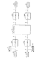
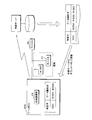
以下、本開示の実施の形態を図面に基づいて説明する。図1は本実施の形態の制御システムの構成の一例を示す模式図である。制御システムは、中央制御装置としてのセントラルECU10、制御装置としてのゾーンECU20A、20B、20C、20Dを備える。ゾーンECU20A、20B、20C、20Dを纏めてゾーンECU20とも称する。セントラルECU10は、各ゾーンECU20を管理する上位のECUとすることができる。図では4個のゾーンECUを備える構成であるが、ゾーンECUは複数個備えればよく、4個に限定されない。セントラルECU10と各ゾーンECU20A、20B、20C、20Dとの間は通信線2によって接続されている。通信線2は、例えば、イーサネット(登録商標)とすることができるが、これに限定されない。 [Details of Embodiments of the present invention]
Hereinafter, embodiments of the present disclosure will be described with reference to the drawings. FIG. 1 is a schematic diagram showing an example of the configuration of the control system of the present embodiment. The control system includes acentral ECU 10 as a central control device and zone ECUs 20A, 20B, 20C, and 20D as control devices. The zone ECUs 20A, 20B, 20C, and 20D are collectively referred to as the zone ECU 20. The central ECU 10 can be a higher-level ECU that manages each zone ECU 20. In the figure, the configuration is provided with four zone ECUs, but a plurality of zone ECUs may be provided, and the number is not limited to four. The central ECU 10 and the zone ECUs 20A, 20B, 20C, and 20D are connected by a communication line 2. The communication line 2 can be, for example, Ethernet (registered trademark), but is not limited thereto.
以下、本開示の実施の形態を図面に基づいて説明する。図1は本実施の形態の制御システムの構成の一例を示す模式図である。制御システムは、中央制御装置としてのセントラルECU10、制御装置としてのゾーンECU20A、20B、20C、20Dを備える。ゾーンECU20A、20B、20C、20Dを纏めてゾーンECU20とも称する。セントラルECU10は、各ゾーンECU20を管理する上位のECUとすることができる。図では4個のゾーンECUを備える構成であるが、ゾーンECUは複数個備えればよく、4個に限定されない。セントラルECU10と各ゾーンECU20A、20B、20C、20Dとの間は通信線2によって接続されている。通信線2は、例えば、イーサネット(登録商標)とすることができるが、これに限定されない。 [Details of Embodiments of the present invention]
Hereinafter, embodiments of the present disclosure will be described with reference to the drawings. FIG. 1 is a schematic diagram showing an example of the configuration of the control system of the present embodiment. The control system includes a
ゾーンECU20A、20B、20C、20Dは、共通の機能又は動作を行う他、それぞれの車両内の制御対象の配置(例えば、車両の前後左右など)に応じて、異なる機能又は動作を行う。例えば、ゾーンECU20Aは、通信線1を介してデバイス31、32と通信可能であり、ゾーンECU20Bは、通信線1を介してデバイス33、34と通信可能であり、ゾーンECU20Cは、通信線1を介してデバイス35と通信可能であり、ゾーンECU20Dは、通信線1を介してデバイス36と通信可能である。通信線1は、例えば、CAN(Controller Area Network)とすることができるが、これに限定されない。
The zone ECUs 20A, 20B, 20C, and 20D perform common functions or operations, and also perform different functions or operations according to the arrangement of controlled objects in each vehicle (for example, front, rear, left, and right of the vehicle). For example, the zone ECU 20A can communicate with the devices 31 and 32 via the communication line 1, the zone ECU 20B can communicate with the devices 33 and 34 via the communication line 1, and the zone ECU 20C can communicate with the devices 33 and 34 via the communication line 1. It can communicate with the device 35 via the communication line 1, and the zone ECU 20D can communicate with the device 36 via the communication line 1. The communication line 1 can be, for example, CAN (Controller Area Network), but is not limited to this.
デバイス31~36は、例えば、アクチュエータ、センサ、スイッチ、ECU(Electronic Control Unit)などを含む。ゾーンECU20A、20B、20C、20Dは、様々な機能を集約したECUということができる。
Devices 31 to 36 include, for example, actuators, sensors, switches, ECUs (Electronic Control Units), and the like. The zone ECUs 20A, 20B, 20C, and 20D can be said to be ECUs that integrate various functions.
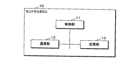
図2はセントラルECU10の構成の一例を示すブロック図である。セントラルECU10は、制御部11、通信部12、記憶部13を備える。制御部11は、CPU、ROM、RAM等で構成することができ、セントラルECU10全体を制御する。
FIG. 2 is a block diagram showing an example of the configuration of the central ECU 10. The central ECU 10 includes a control unit 11, a communication unit 12, and a storage unit 13. The control unit 11 can be composed of a CPU, ROM, RAM, etc., and controls the entire central ECU 10.
通信部12は、通信線2で定められている通信プロトコルを用いて、各ゾーンECU20A、20B、20C、20Dと通信を行う機能を有する。
The communication unit 12 has a function of communicating with each of the zone ECUs 20A, 20B, 20C, and 20D using the communication protocol defined by the communication line 2.
記憶部13は、例えば、半導体メモリ等で構成することができ、各ゾーンECU20A、20B、20C、20Dから受信した情報を記憶することができる。また、記憶部13は、各ゾーンECU20A、20B、20C、20Dへ送信する情報を記憶することができる。記憶部13は、各ゾーンECU20A、20B、20C、20Dの特定子が決定済であるか否かの情報を記憶することができる。特定子は、各ゾーンECU20A、20B、20C、20Dの機能又は動作を特定するものである。
The storage unit 13 can be configured by, for example, a semiconductor memory or the like, and can store information received from each of the zone ECUs 20A, 20B, 20C, and 20D. Further, the storage unit 13 can store information to be transmitted to each of the zone ECUs 20A, 20B, 20C, and 20D. The storage unit 13 can store information on whether or not the specific elements of the zone ECUs 20A, 20B, 20C, and 20D have been determined. The specifier specifies the function or operation of each zone ECU 20A, 20B, 20C, 20D.
制御部11は、後述のように、一のゾーンECUが特定子の未決定をセントラルECU10に通知した場合、記憶部13に記憶した情報に基づいて、当該一のゾーンECUの特定子を決定することができる。特定子が未決定とは、搭載位置が未割当であるとうこともできる。特定子の決定方法の詳細は後述する。
As will be described later, when one zone ECU notifies the central ECU 10 that the specific element has not been determined, the control unit 11 determines the specific child of the one zone ECU based on the information stored in the storage unit 13. be able to. The fact that the specific child is undecided can also mean that the mounting position is unassigned. The details of the method for determining the specific child will be described later.
制御部11は、決定した特定子を一のゾーンECU(特定子が未決定である旨を通知したゾーンECU)へ通知することができる。また、制御部11は、特定子が未決定のゾーンECUがあった場合、異常として警告を出力することができる。警告の出力は、表示による出力形態でもよく、音声による出力形態でもよい。
The control unit 11 can notify the determined specific child to one zone ECU (the zone ECU that has notified that the specific child is undecided). Further, the control unit 11 can output a warning as an abnormality when there is a zone ECU in which the specific element is undecided. The warning output may be in the form of display or in the form of voice output.
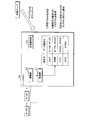
図3はゾーンECU20の構成の一例を示すブロック図である。ゾーンECU20は、制御部21、通信部22、広域通信部23、記憶部24、エラーログ記録部25を備える。制御部21は、CPU、ROM、RAM等で構成することができ、ゾーンECU20全体を制御する。
FIG. 3 is a block diagram showing an example of the configuration of the zone ECU 20. The zone ECU 20 includes a control unit 21, a communication unit 22, a wide area communication unit 23, a storage unit 24, and an error log recording unit 25. The control unit 21 can be composed of a CPU, ROM, RAM, etc., and controls the entire zone ECU 20.
通信部22は、通信線1で定められている通信プロトコルを用いて、当該ゾーンECUと接続されるデバイス(31~36のいずれか)と通信を行う機能を有する。通信部22は、受信部としての機能を有し、通信線1を介してデバイス(送信元デバイス)からデータ識別子を受信することができる。データ識別子は、データの送信元デバイスを識別するものであり、例えば、通信プロトコルがCANである場合、CAN-IDを用いることができる。また、通信部22は、通信線2で定められている通信プロトコルを用いて、セントラルECU10と通信を行う機能を有する。
The communication unit 22 has a function of communicating with a device (any of 31 to 36) connected to the zone ECU using the communication protocol defined by the communication line 1. The communication unit 22 has a function as a reception unit, and can receive a data identifier from a device (source device) via the communication line 1. The data identifier identifies the device that is the source of the data. For example, when the communication protocol is CAN, CAN-ID can be used. Further, the communication unit 22 has a function of communicating with the central ECU 10 by using the communication protocol defined by the communication line 2.
広域通信部23は、インターネットや電話回線等を通じて外部サーバ(関連情報提供装置、プログラム提供装置)とデータの送受信を行うことができる。
The wide area communication unit 23 can send and receive data to and from an external server (related information providing device, program providing device) via the Internet, a telephone line, or the like.
記憶部24は、例えば、半導体メモリ等で構成することができ、関連情報を記憶することができる。関連情報の詳細は後述する。
The storage unit 24 can be configured by, for example, a semiconductor memory or the like, and can store related information. Details of the related information will be described later.
制御部21は、通信部22で受信したデータ識別子及び記憶部24に記憶した関連情報に基づいて当該ゾーンECUの特定子を決定することができる。特定子の決定方法の詳細は後述する。
The control unit 21 can determine the specific child of the zone ECU based on the data identifier received by the communication unit 22 and the related information stored in the storage unit 24. The details of the method for determining the specific child will be described later.
制御部21は、記憶部24に記憶した関連情報を、外部のサーバから取得した関連情報によって更新することができる。
The control unit 21 can update the related information stored in the storage unit 24 with the related information acquired from the external server.
エラーログ記録部25は、記録部としての機能を有し、通信部22で受信したデータ識別子が記憶部24に記憶した関連情報に含まれていない場合、データ識別子をエラーログとして記録することができる。
The error log recording unit 25 has a function as a recording unit, and when the data identifier received by the communication unit 22 is not included in the related information stored in the storage unit 24, the error log recording unit 25 may record the data identifier as an error log. can.
次に、関連情報について説明する。
Next, related information will be explained.
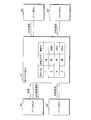
図4は関連情報の一例を示す模式図である。関連情報は、ゾーンECUの機能又は動作を特定する特定子と、当該ゾーンECUに対してデータを送信する送信元デバイスを識別するデータ識別子とを、複数の特定子毎に関連付けた情報である。図4に示すように、関連情報は、機能又は動作、特定子、データ識別子、送信元デバイスの各項目で構成することができる。
FIG. 4 is a schematic diagram showing an example of related information. The related information is information in which a specific element that specifies the function or operation of the zone ECU and a data identifier that identifies a source device that transmits data to the zone ECU are associated with each of a plurality of specific elements. As shown in FIG. 4, the related information can be composed of each item of function or operation, specific child, data identifier, and source device.
車両の製造段階又は組立段階において、車両に搭載される各ゾーンECUの記憶部24には、同じ関連情報が記憶される。例えば、車両に4個のゾーンECUが搭載されるとし、車両内の搭載位置等に応じて、4個のゾーンECUの異なる機能又は動作をA、B、C、Dで表し、機能又は動作A、B、C、Dそれぞれを特定する特定子を、AAA、BBB、CCC、DDDで表すとする。
At the vehicle manufacturing stage or assembly stage, the same related information is stored in the storage unit 24 of each zone ECU mounted on the vehicle. For example, assuming that four zone ECUs are mounted on a vehicle, different functions or operations of the four zone ECUs are represented by A, B, C, and D according to the mounting position in the vehicle, and the functions or actions A. , B, C, and D are specified by AAA, BBB, CCC, and DDD.
また、機能又は動作がAのゾーンECUは、送信元デバイス32からデータ識別子#100を受信し、送信元デバイス31からデータ識別子#150を受信するとする。ゾーンECUと各送信元デバイスの車両内の搭載位置から、ゾーンECUの機能又は動作(すなわち、特定子)とデータを送受信するデバイスとは予め対応付けすることができる。同様に、機能又は動作がBのゾーンECUは、送信元デバイス33からデータ識別子#170を受信し、送信元デバイス34からデータ識別子#200を受信するとする。機能又は動作がCのゾーンECUは、送信元デバイス35からデータ識別子#250、#300を受信するとし、機能又は動作がDのゾーンECUは、送信元デバイス36からデータ識別子#350を受信するとする。
Further, it is assumed that the zone ECU having the function or operation A receives the data identifier # 100 from the source device 32 and the data identifier # 150 from the source device 31. From the mounting position of the zone ECU and each source device in the vehicle, the function or operation (that is, the specific element) of the zone ECU can be associated with the device that transmits / receives data in advance. Similarly, it is assumed that the zone ECU having the function or operation B receives the data identifier # 170 from the source device 33 and the data identifier # 200 from the source device 34. It is assumed that the zone ECU having the function or operation C receives the data identifiers # 250 and # 300 from the source device 35, and the zone ECU having the function or operation D receives the data identifier # 350 from the source device 36. ..
車両の製造段階又は組立段階において、車両に搭載される各ゾーンECUは、例えば、同一の品番で製造されており、共通化されている。すなわち、各ゾーンECUは、車両に組み込んだ時点では、自身がいずれの機能又は動作を行うゾーンECUであるかは決定されていない。
At the vehicle manufacturing stage or assembly stage, each zone ECU mounted on the vehicle is manufactured with the same part number, for example, and is standardized. That is, at the time of incorporating each zone ECU into the vehicle, it has not been determined which function or operation the zone ECU itself performs.
次に、各ゾーンECU20の機能又は動作の決定方法について説明する。
Next, a method of determining the function or operation of each zone ECU 20 will be described.
図5はゾーンECU20の機能又は動作の決定方法の一例を示す模式図である。ゾーンECUや各デバイスを車両に組み込み、各部が通信線で接続された状態で(製造段階又は組立段階)、例えば、システムの電源を投入して動作を開始させることにより、各デバイスは、予め定められた手順に従って、データを周期的にゾーンECUへ送信することができる。
FIG. 5 is a schematic diagram showing an example of a function or a method of determining the operation of the zone ECU 20. Each device is predetermined by incorporating the zone ECU and each device into the vehicle and starting the operation by turning on the power of the system, for example, in the state where each part is connected by a communication line (manufacturing stage or assembly stage). Data can be periodically transmitted to the zone ECU according to the procedure.
通信部22は、通信線1を介して送信元デバイスからデータ識別子を受信する。共通の制御装置を車両に組み込んだ製造段階又は組立段階において、各送信元デバイスからデータの送信を開始することによって、通信部22はデータ識別子を受信することができる。図5の例では、データ識別子を、#100、#150とする。
The communication unit 22 receives the data identifier from the source device via the communication line 1. The communication unit 22 can receive the data identifier by starting the transmission of data from each source device in the manufacturing stage or the assembly stage in which the common control device is incorporated in the vehicle. In the example of FIG. 5, the data identifiers are # 100 and # 150.
制御部21は、通信部22で受信したデータ識別子及び記憶部24に記憶した関連情報に基づいてゾーンECU20の特定子を決定する。図5の例では、受信したデータ識別子#100、#150に対応する特定子は、特定子AAAであることが分かるので、ゾーンECU20の機能又は動作は、機能又は動作Aであると決定することができる。他のゾーンECUについても、同様にして特定子を決定することができ、機能又は動作も決定できる。このように、各ゾーンECUの機能又は動作を自動的に決定することができ、製造要員などによる手作業も不要である。
The control unit 21 determines the specific child of the zone ECU 20 based on the data identifier received by the communication unit 22 and the related information stored in the storage unit 24. In the example of FIG. 5, since it can be seen that the specifier corresponding to the received data identifiers # 100 and # 150 is the specifier AAA, it is determined that the function or operation of the zone ECU 20 is the function or operation A. Can be done. For other zone ECUs, the specific child can be determined in the same manner, and the function or operation can also be determined. In this way, the function or operation of each zone ECU can be automatically determined, and manual work by manufacturing personnel or the like is unnecessary.
すなわち、共通化された汎用のゾーンECUを車両に組み込み、製造段階又は組立段階において、車両内のそれぞれのゾーンECUの機能又は動作を決定することができる。これにより、共通化された汎用のゾーンECUを製造して、車両の製造段階や組立段階で、それぞれのゾーンECUの機能又は動作を決定できるので、予め機能や動作が異なるECUを個別に製造する必要がなく、製造コストを低減することができる。
That is, a common general-purpose zone ECU can be incorporated into a vehicle, and the function or operation of each zone ECU in the vehicle can be determined at the manufacturing stage or the assembly stage. As a result, a common general-purpose zone ECU can be manufactured, and the function or operation of each zone ECU can be determined at the manufacturing stage or the assembly stage of the vehicle. Therefore, ECUs having different functions and operations are individually manufactured in advance. There is no need, and the manufacturing cost can be reduced.
制御部21は、広域通信部23を介して、決定した特定子をプログラム提供装置としての外部サーバへ出力する。外部サーバは、例えば、共通化された汎用のゾーンECUに、機能又は動作別のプログラムを導入することにより、共通化された汎用のゾーンECUを、機能又は動作別のゾーンECUに変更することができる。
The control unit 21 outputs the determined specific child to an external server as a program providing device via the wide area communication unit 23. The external server may change the common general-purpose zone ECU to a common general-purpose zone ECU by introducing a function or operation-specific program into the common general-purpose zone ECU, for example. can.
制御部21は、広域通信部23を介して、外部サーバから特定子で特定される機能又は動作を実現するためのプログラムを取得することができる。ゾーンECU20は、取得したプログラムを導入(インストール)することにより、特定子で特定される機能又は動作を実現することができる。すなわち、車両の製造段階又は組立段階において、共通化された汎用のゾーンECU20を、機能又は動作別のゾーンECU20に変更することができる。なお、プログラムを取得するとは、プログラムの全部又は一部を取得することの他に、ゾーンECU20のプログラムが読み込むパラメータ(例えば、コンフィグファイル)を取得することも含む。
The control unit 21 can acquire a program for realizing a function or operation specified by a specific child from an external server via the wide area communication unit 23. The zone ECU 20 can realize a function or operation specified by a specific child by introducing (installing) the acquired program. That is, at the vehicle manufacturing stage or assembly stage, the common general-purpose zone ECU 20 can be changed to a zone ECU 20 according to function or operation. In addition to acquiring all or part of the program, acquiring the program also includes acquiring parameters (for example, a config file) read by the program of the zone ECU 20.
制御部21は、外部サーバから取得したプログラムに基づく処理を実行することができる。これにより、車両に搭載されたゾーンECU20それぞれは、共通の機能又は動作だけでなく、例えば、車両の搭載位置に応じた独自の機能又は動作を実行することができる。なお、プログラムの取得先は、外部サーバに限定されるものではない。例えば、セントラルECU10に予め各ゾーンECUの異なる機能又は動作を実現するためのプログラムを記憶しておき、セントラルECU10からプログラムを取得してもよい。
The control unit 21 can execute processing based on the program acquired from the external server. As a result, each of the zone ECUs 20 mounted on the vehicle can execute not only a common function or operation but also a unique function or operation according to the mounting position of the vehicle, for example. The acquisition destination of the program is not limited to the external server. For example, a program for realizing different functions or operations of each zone ECU may be stored in the central ECU 10 in advance, and the program may be acquired from the central ECU 10.
制御部21は、通信部22を介して、決定した特定子をセントラルECU10へ通知することができる。これにより、セントラルECU10は、各ゾーンECU20が、機能又は動作を決定することができたか否かを判定することができる。
The control unit 21 can notify the central ECU 10 of the determined specific child via the communication unit 22. Thereby, the central ECU 10 can determine whether or not each zone ECU 20 has been able to determine the function or operation.
次に、ゾーンECU20が機能又は動作を決定できない場合について説明する。
Next, a case where the zone ECU 20 cannot determine the function or operation will be described.
図6はゾーンECU20が機能又は動作を決定できない場合の処理の一例を示す模式図である。エラーログ記録部25は、通信部22で受信したデータ識別子が記憶部24に記憶した関連情報に含まれていない場合、データ識別子をエラーログとして記録することができる。図の例では、通信部22は、データ識別子#110を受信したが、データ識別子#110に対応する特定子は存在していない。また、データ識別子の送信元デバイスをエラーログに記録することもできる。例えば、図4の例では、仮にデータ識別子#100を受信し、データ識別子#150に代わりにデータ識別子#110を受信しているとすると、デバイス31をエラーログに記録することができる。受信したデータ識別子が記憶部24に記憶した関連情報に含まれていない場合、データ通信において、データ化けが発生している可能性が高い。データ化けの原因としては、送信元のデバイスの不良、通信線のコネクタ等の接続不良など種々の要因が考えられる。そこで、エラーログを記録することにより、不良原因を特定し、所要の対策を行うことができる。
FIG. 6 is a schematic diagram showing an example of processing when the zone ECU 20 cannot determine the function or operation. The error log recording unit 25 can record the data identifier as an error log when the data identifier received by the communication unit 22 is not included in the related information stored in the storage unit 24. In the example of the figure, the communication unit 22 receives the data identifier # 110, but the specific child corresponding to the data identifier # 110 does not exist. It is also possible to record the source device of the data identifier in the error log. For example, in the example of FIG. 4, assuming that the data identifier # 100 is received and the data identifier # 110 is received instead of the data identifier # 150, the device 31 can be recorded in the error log. If the received data identifier is not included in the related information stored in the storage unit 24, there is a high possibility that data garbled has occurred in the data communication. Various factors such as a defective device of the transmitting source and a poor connection of the connector of the communication line can be considered as the cause of the garbled data. Therefore, by recording the error log, the cause of the defect can be identified and necessary countermeasures can be taken.
制御部21は、通信部22を介して、受信したデータ識別子が記憶部24に記憶した関連情報に含まれていない場合、特定子の未決定をセントラルECU10へ通知することができる。これにより、セントラルECU10は、各ゾーンECU20が、機能又は動作を決定することができたか否かを判定することができる。
The control unit 21 can notify the central ECU 10 of the undecided specific child when the received data identifier is not included in the related information stored in the storage unit 24 via the communication unit 22. Thereby, the central ECU 10 can determine whether or not each zone ECU 20 has been able to determine the function or operation.
次に、セントラルECU10によるゾーンECU20の機能又は動作の決定方法について説明する。
Next, a method of determining the function or operation of the zone ECU 20 by the central ECU 10 will be described.
図7はセントラルECU10によるゾーンECU20の機能又は動作の決定方法の一例を示す模式図である。セントラルECU10の記憶部13は、各ゾーンECU20の特定子が決定済であるか否かの情報を記憶することができる。図7に示すように、車両に4個のゾーンECU20が搭載されるとし、ゾーンECU20の機能又は動作をA、B、C、Dで表し、機能又は動作A、B、C、Dを特定する特定子を、AAA、BBB、CCC、DDDで表すとする。4個のゾーンECU20のうち、3個のゾーンECU20から、それぞれ特定子がBBB、CCC、DDDであると決定した旨の通知がされ、残りの1個のゾーンECU20から特定子が未決定の通知を受けたとする。セントラルECU10は、特定子が未決定のゾーンECU20の特定子がAAA(BBB、CCC及びDDD以外)であると決定し、当該ゾーンECU20へ通知する。これにより、自身では特定子を決定できないゾーンECU20が存在しても、セントラルECU10によって、特定子を決定することができる。
FIG. 7 is a schematic diagram showing an example of a function or a method of determining the operation of the zone ECU 20 by the central ECU 10. The storage unit 13 of the central ECU 10 can store information on whether or not the specific element of each zone ECU 20 has been determined. As shown in FIG. 7, assuming that four zone ECUs 20 are mounted on the vehicle, the functions or operations of the zone ECU 20 are represented by A, B, C, and D, and the functions or operations A, B, C, and D are specified. It is assumed that the specific child is represented by AAA, BBB, CCC, and DDD. Of the four zone ECUs 20, three zone ECUs 20 notify that the specific child is BBB, CCC, and DDD, respectively, and the remaining one zone ECU 20 notifies that the specific child is undecided. Suppose you received. The central ECU 10 determines that the specific child of the zone ECU 20 whose specific child is undecided is AAA (other than BBB, CCC and DDD), and notifies the zone ECU 20. As a result, even if there is a zone ECU 20 that cannot determine the specific child by itself, the central ECU 10 can determine the specific child.
次に、関連情報の更新方法について説明する。
Next, the method of updating related information will be explained.
図8は関連情報の更新方法の一例を示す模式図である。図8に示すように、オプションやカスタマイズによって新たなデバイス37が追加され、デバイス37からデータ識別子#160が送信されたとする。この場合、ゾーンECU20Cは、関連情報(特定子CCCと、データ識別子#250、#300との関連付け情報)に含まれていないデータ識別子#160を受信する。この場合、制御部21は、広域通信部23を介して、関連情報提供装置としての外部サーバから最新の関連情報を取得することができる。制御部21は、記憶部24に記憶した関連情報を、外部サーバからで取得した関連情報で更新する。
FIG. 8 is a schematic diagram showing an example of how to update related information. As shown in FIG. 8, it is assumed that a new device 37 is added by options or customization, and the data identifier # 160 is transmitted from the device 37. In this case, the zone ECU 20C receives the data identifier # 160 which is not included in the related information (the association information between the specific child CCC and the data identifiers # 250 and # 300). In this case, the control unit 21 can acquire the latest related information from the external server as the related information providing device via the wide area communication unit 23. The control unit 21 updates the related information stored in the storage unit 24 with the related information acquired from the external server.
このように、車両に各ゾーンECU20が搭載され、オプションやカスタマイズによって新たな送信元デバイス(ECUも含む)が追加された場合、記憶部24に記憶した関連情報に、新たに追加した送信元デバイスの情報が記憶されていない場合がある。そのような場合に、関連情報を更新することにより、関連情報を最新の情報にすることができる。なお、仮に更新しても関連情報にないデータ識別子を受信する場合には、異常を報知してもよい。
In this way, when each zone ECU 20 is mounted on the vehicle and a new source device (including the ECU) is added by options or customization, the newly added source device is added to the related information stored in the storage unit 24. Information may not be stored. In such a case, the related information can be updated to the latest information by updating the related information. If a data identifier that is not included in the related information is received even if it is updated, an abnormality may be notified.
図9は本実施の形態の制御システムの処理手順の一例を示すフローチャートである。セントラルECU10は、関連情報を設定する(S11)。関連情報の設定は、車両の製造段階又は組立段階において、作業者の指定により行うことができる。セントラルECU10は、関連情報を各ゾーンECU20へ送信する(S12)。
FIG. 9 is a flowchart showing an example of the processing procedure of the control system of the present embodiment. The central ECU 10 sets related information (S11). The related information can be set by the operator at the manufacturing stage or the assembling stage of the vehicle. The central ECU 10 transmits related information to each zone ECU 20 (S12).
ゾーンECU20は、関連情報を受信し、記憶する(S31)。ゾーンECU20は、デバイス(送信元デバイス)からデータ識別子を受信し(S32)、ゾーンECUの特定子を決定可であるか否かを判定する(S33)。特定子を決定できる場合(S33でYES)、ゾーンECU20は、決定した特定子に対応するプログラムをダウンロードし(S34)、決定した特定子をセントラルECU10に通知し(S35)、処理を終了する。セントラルECU10は後述のステップS13の処理を行う。
The zone ECU 20 receives and stores the related information (S31). The zone ECU 20 receives the data identifier from the device (source device) (S32), and determines whether or not the specific child of the zone ECU can be determined (S33). When the specific child can be determined (YES in S33), the zone ECU 20 downloads the program corresponding to the determined specific child (S34), notifies the determined specific child to the central ECU 10 (S35), and ends the process. The central ECU 10 performs the process of step S13 described later.
特定子を決定できない場合(S33でNO)、ゾーンECU20は、エラーログを記録し(S36)、特定子が未決定であることをセントラルECU10に通知し(S37)、セントラルECU10は後述のステップS14の処理を行う。
When the specific child cannot be determined (NO in S33), the zone ECU 20 records an error log (S36), notifies the central ECU 10 that the specific child has not been determined (S37), and the central ECU 10 notifies the central ECU 10 that the specific child has not been determined (S37). Process.
セントラルECU10は、特定子を決定済として記録し(S13)、後述のステップS15の処理を行う。また、セントラルECU10は、特定子を未決定として記録し(S14)、特定子が未決定のゾーンECU20の有無を判定する(S15)。特定子が未決定のゾーンECU20がある場合(S15でYES)、セントラルECU10は、特定子が未決定のゾーンECUの特定子を決定し、ゾーンECU20に通知し(S16)、ゾーンECU20は後述のステップS38の処理を行う。特定子が未決定のゾーンECU20がない場合(S15でNO)、セントラルECU10は、処理を終了する。
The central ECU 10 records the specific child as determined (S13), and performs the process of step S15 described later. Further, the central ECU 10 records the specific child as undecided (S14), and determines the presence or absence of the zone ECU 20 in which the specific child is undecided (S15). When there is a zone ECU 20 in which the specific child is undecided (YES in S15), the central ECU 10 determines the specific child of the zone ECU in which the specific child is undecided and notifies the zone ECU 20 (S16), and the zone ECU 20 will be described later. The process of step S38 is performed. When there is no zone ECU 20 in which the specific child is undetermined (NO in S15), the central ECU 10 ends the process.
ゾーンECU20は、セントラルECU10から特定子の通知の有無を判定し(S38)、通知がない場合(S38でNO)、ステップS38の処理を続ける。通知があった場合(S38でYES)、ゾーンECU20は、特定子を決定し(S39)、処理を終了する。
The zone ECU 20 determines whether or not there is a notification of the specific child from the central ECU 10 (S38), and if there is no notification (NO in S38), the process of step S38 is continued. When notified (YES in S38), the zone ECU 20 determines a specific child (S39) and ends the process.
本実施の形態において、各ゾーンECUは、電力分配器としての機能も備えることができる。例えば、バッテリからの電力を、ゾーンECUを介して、デバイスへ供給することができる。
In the present embodiment, each zone ECU can also have a function as a power distributor. For example, power from the battery can be supplied to the device via the zone ECU.
以上に開示された実施の形態及び実施例は、全ての点で例示であって制限的なものではないと考慮されるべきである。本開示の範囲は、以上の実施の形態及び実施例ではなく、特許請求の範囲によって示され、特許請求の範囲と均等の意味及び範囲内での全ての修正や変形を含むものと意図される。
It should be considered that the embodiments and examples disclosed above are exemplary in all respects and not restrictive. The scope of the present disclosure is shown by the scope of claims, not the above embodiments and examples, and is intended to include all modifications and modifications within the meaning and scope equivalent to the scope of claims. ..
1、2 通信線
10 セントラルECU
11 制御部
12 通信部
13 記憶部
20 ゾーンECU
21 制御部
22 通信部
23 広域通信部
24 記憶部
25 エラーログ記録部
31、32、33、34、35、36、37 デバイス
1, 2communication line 10 Central ECU
11Control unit 12 Communication unit 13 Storage unit 20 Zone ECU
21Control unit 22 Communication unit 23 Wide area communication unit 24 Storage unit 25 Error log recording unit 31, 32, 33, 34, 35, 36, 37 devices
10 セントラルECU
11 制御部
12 通信部
13 記憶部
20 ゾーンECU
21 制御部
22 通信部
23 広域通信部
24 記憶部
25 エラーログ記録部
31、32、33、34、35、36、37 デバイス
1, 2
11
21
Claims (11)
- 制御装置の機能又は動作を特定する特定子とデータの送信元デバイスを識別するデータ識別子とを、複数の特定子毎に関連付けた関連情報を記憶する記憶部と、
通信線を介して送信元デバイスからデータ識別子を受信する受信部と、
制御部と
を備え、
前記制御部は、
前記受信部で受信したデータ識別子及び前記関連情報に基づいて自身の特定子を決定する制御装置。 A storage unit that stores related information in which a specific child that identifies a function or operation of a control device and a data identifier that identifies a data source device are associated with each of a plurality of specific children.
A receiver that receives a data identifier from a source device via a communication line,
Equipped with a control unit
The control unit
A control device that determines its own specific child based on the data identifier received by the receiving unit and the related information. - 前記制御部は、
前記受信部で受信したデータ識別子に基づいて前記記憶部に記憶した関連情報を参照し、受信したデータ識別子と一致するデータ識別子に関連付けられた特定子を自身の特定子として決定する請求項1に記載の制御装置。 The control unit
The first aspect of claim 1 is to refer to the related information stored in the storage unit based on the data identifier received by the receiving unit, and determine the specific child associated with the data identifier that matches the received data identifier as its own specific child. The control device described. - 前記制御部は、
決定した特定子をプログラム提供装置へ出力し、
前記プログラム提供装置から前記特定子で特定される機能又は動作を実現するためのプログラムを取得する請求項1又は請求項2に記載の制御装置。 The control unit
Output the determined specific child to the program providing device,
The control device according to claim 1 or 2, wherein a program for realizing a function or operation specified by the specific child is acquired from the program providing device. - 前記制御部は、
取得したプログラムに基づく処理を実行する請求項3に記載の制御装置。 The control unit
The control device according to claim 3, which executes processing based on the acquired program. - 前記制御部は、
前記受信部で受信したデータ識別子が前記関連情報に含まれていない場合、関連情報提供装置から関連情報を取得し、
前記記憶部に記憶した関連情報を、取得した関連情報によって更新する請求項1から請求項4のいずれか一項に記載の制御装置。 The control unit
When the data identifier received by the receiving unit is not included in the related information, the related information is acquired from the related information providing device, and the related information is acquired.
The control device according to any one of claims 1 to 4, wherein the related information stored in the storage unit is updated by the acquired related information. - 前記受信部で受信したデータ識別子が前記記憶部に記憶した関連情報に含まれていない場合、前記データ識別子をエラーログとして記録する記録部を備える請求項1から請求項5のいずれか一項に記載の制御装置。 If the data identifier received by the receiving unit is not included in the related information stored in the storage unit, any one of claims 1 to 5 includes a recording unit that records the data identifier as an error log. The control device described.
- 前記制御部は、
前記受信部で受信したデータ識別子が前記記憶部に記憶した関連情報に含まれていない場合、特定子の未決定を中央制御装置へ通知する請求項1から請求項6のいずれか一項に記載の制御装置。 The control unit
6. Control device. - 前記制御部は、
決定した特定子を前記中央制御装置へ通知する請求項7に記載の制御装置。 The control unit
The control device according to claim 7, wherein the determined specific child is notified to the central control device. - 機能又は動作が異なる複数の請求項1から請求項8のいずれか一項に記載の制御装置と、
通信線を介して前記複数の制御装置と接続された中央制御装置と
を備える制御システム。 The control device according to any one of claims 1 to 8, which has a different function or operation.
A control system including a central control device connected to the plurality of control devices via a communication line. - 前記中央制御装置は、
前記複数の制御装置それぞれの特定子が決定されているか否かの情報を記憶する記憶部と、
制御部と
を備え、
前記制御部は、
一の制御装置が特定子の未決定を自身に通知した場合、前記記憶部に記憶した情報に基づいて、前記一の制御装置の特定子を決定し、
決定した特定子を前記一の制御装置へ通知する請求項9に記載の制御システム。 The central control device
A storage unit that stores information on whether or not a specific child for each of the plurality of control devices has been determined, and a storage unit.
Equipped with a control unit
The control unit
When one control device notifies itself of the undecided specific child, the specific child of the one control device is determined based on the information stored in the storage unit.
The control system according to claim 9, wherein the determined specific child is notified to the one control device. - 制御装置の機能又は動作を特定する特定子とデータの送信元デバイスを識別するデータ識別子とを、複数の特定子毎に関連付けた関連情報を記憶部に記憶し、
通信線を介して送信元デバイスからデータ識別子を受信し、
受信されたデータ識別子及び前記関連情報に基づいて特定子を決定する、制御装置の機能又は動作の決定方法。
A specific child that identifies the function or operation of the control device and a data identifier that identifies the data source device are stored in the storage unit in relation to each of a plurality of specific children.
Receive the data identifier from the source device via the communication line
A method for determining a function or operation of a control device, which determines a specific child based on a received data identifier and the related information.
Priority Applications (2)
| Application Number | Priority Date | Filing Date | Title |
|---|---|---|---|
| CN202180008069.7A CN114930308A (en) | 2020-01-24 | 2021-01-15 | Control device, control system, and method for determining function or operation of control device |
| US17/759,253 US20230052810A1 (en) | 2020-01-24 | 2021-01-15 | Control apparatus, control system, and method for determining function or operation of control apparatus |
Applications Claiming Priority (2)
| Application Number | Priority Date | Filing Date | Title |
|---|---|---|---|
| JP2020-010238 | 2020-01-24 | ||
| JP2020010238A JP7375573B2 (en) | 2020-01-24 | 2020-01-24 | Control devices, control systems and methods for determining the function or operation of control devices |
Publications (1)
| Publication Number | Publication Date |
|---|---|
| WO2021149597A1 true WO2021149597A1 (en) | 2021-07-29 |
Family
ID=76992744
Family Applications (1)
| Application Number | Title | Priority Date | Filing Date |
|---|---|---|---|
| PCT/JP2021/001146 WO2021149597A1 (en) | 2020-01-24 | 2021-01-15 | Control apparatus, control system, and method for determining function or operation of control apparatus |
Country Status (4)
| Country | Link |
|---|---|
| US (1) | US20230052810A1 (en) |
| JP (2) | JP7375573B2 (en) |
| CN (1) | CN114930308A (en) |
| WO (1) | WO2021149597A1 (en) |
Families Citing this family (1)
| Publication number | Priority date | Publication date | Assignee | Title |
|---|---|---|---|---|
| JP7307116B2 (en) * | 2021-04-07 | 2023-07-11 | 矢崎総業株式会社 | IN-VEHICLE SOFTWARE UPDATE METHOD AND IN-VEHICLE SYSTEM |
Citations (2)
| Publication number | Priority date | Publication date | Assignee | Title |
|---|---|---|---|---|
| JP2007109007A (en) * | 2005-10-13 | 2007-04-26 | Matsushita Electric Ind Co Ltd | Mobile terminal device |
| JP2019034684A (en) * | 2017-08-21 | 2019-03-07 | 住友電気工業株式会社 | On-vehicle device control system, management server, on-vehicle communication device, computer program, and on-vehicle device control method |
Family Cites Families (7)
| Publication number | Priority date | Publication date | Assignee | Title |
|---|---|---|---|---|
| JP5345500B2 (en) * | 2009-10-16 | 2013-11-20 | 日本電信電話株式会社 | Transfer control method, transfer control device, transfer control system, and transfer control program |
| JP5741496B2 (en) * | 2012-03-14 | 2015-07-01 | 株式会社オートネットワーク技術研究所 | In-vehicle communication system |
| JP6170844B2 (en) * | 2014-02-14 | 2017-07-26 | 株式会社Nttドコモ | Authentication information management system |
| WO2015133181A1 (en) * | 2014-03-04 | 2015-09-11 | 日本電気株式会社 | Communication apparatus, communication control method, and recording medium |
| JP5665207B1 (en) * | 2014-03-21 | 2015-02-04 | 株式会社イッカツ | Information input system, information input method, and information input program |
| WO2018167821A1 (en) * | 2017-03-13 | 2018-09-20 | 三菱電機株式会社 | Communication device, server, communication system, communication method, and program |
| JP6868582B2 (en) * | 2018-02-27 | 2021-05-12 | Kddi株式会社 | Relay device, communication system and communication history storage method |
-
2020
- 2020-01-24 JP JP2020010238A patent/JP7375573B2/en active Active
-
2021
- 2021-01-15 WO PCT/JP2021/001146 patent/WO2021149597A1/en active Application Filing
- 2021-01-15 US US17/759,253 patent/US20230052810A1/en active Pending
- 2021-01-15 CN CN202180008069.7A patent/CN114930308A/en active Pending
-
2023
- 2023-10-18 JP JP2023179604A patent/JP2023182795A/en active Pending
Patent Citations (2)
| Publication number | Priority date | Publication date | Assignee | Title |
|---|---|---|---|---|
| JP2007109007A (en) * | 2005-10-13 | 2007-04-26 | Matsushita Electric Ind Co Ltd | Mobile terminal device |
| JP2019034684A (en) * | 2017-08-21 | 2019-03-07 | 住友電気工業株式会社 | On-vehicle device control system, management server, on-vehicle communication device, computer program, and on-vehicle device control method |
Also Published As
| Publication number | Publication date |
|---|---|
| US20230052810A1 (en) | 2023-02-16 |
| JP7375573B2 (en) | 2023-11-08 |
| CN114930308A (en) | 2022-08-19 |
| JP2021117694A (en) | 2021-08-10 |
| JP2023182795A (en) | 2023-12-26 |
Similar Documents
| Publication | Publication Date | Title |
|---|---|---|
| JP4416649B2 (en) | Method and apparatus for telematic services for vehicles | |
| US6907331B2 (en) | Vehicle control system and apparatus therefor | |
| JP4593626B2 (en) | In-vehicle database system | |
| WO2014148003A1 (en) | Program rewrite system for onboard electronic control device and onboard relay device | |
| WO2013136872A1 (en) | In-vehicle communication system | |
| US20080004726A1 (en) | Connection module for sensors | |
| US10581739B2 (en) | System for verification of unregistered device based on information of Ethernet switch and method for the same | |
| JP2023182795A (en) | Control device, control system, and method for determining function or operation of control device | |
| US20220185206A1 (en) | Configurable management system for a vehicle and method of use | |
| CA2434782A1 (en) | Network comprising a number of nodes, and a corresponding node for a network of this type | |
| CN109960233B (en) | Method and apparatus for automatically configuring replacement field devices in a process control system | |
| US20120210030A1 (en) | Automation system and method for operating an automation system | |
| KR101886076B1 (en) | System and method for managing control device of network | |
| US20060268854A1 (en) | Auto-addressing system and method | |
| US11301236B2 (en) | Updating components of a modular system | |
| JP4039457B2 (en) | IDENTIFICATION INFORMATION AUTOMATIC GENERATION DEVICE, INFORMATION STORAGE SYSTEM, AND INFORMATION STORAGE SYSTEM INFORMATION ACQUISITION METHOD | |
| JP7419851B2 (en) | lighting control system | |
| WO2024095683A1 (en) | Setting device and on-vehicle apparatus | |
| DK181360B1 (en) | Communication system with accessory device configuration | |
| WO2022153591A1 (en) | Vehicle control device, vehicle system and update system | |
| US11435950B2 (en) | Data rewriting method and data rewriting system | |
| WO2023223819A1 (en) | Information processing method, communication system, and information processing program | |
| US20210382453A1 (en) | Method for modifying a control software of an automation system | |
| WO2023223825A1 (en) | Vehicle-mounted device, information processing method, and information processing program | |
| CN116430803A (en) | System for connecting a machine to a production line |
Legal Events
| Date | Code | Title | Description |
|---|---|---|---|
| 121 | Ep: the epo has been informed by wipo that ep was designated in this application |
Ref document number: 21743944 Country of ref document: EP Kind code of ref document: A1 |
|
| NENP | Non-entry into the national phase |
Ref country code: DE |
|
| 122 | Ep: pct application non-entry in european phase |
Ref document number: 21743944 Country of ref document: EP Kind code of ref document: A1 |