WO2021149300A1 - 電池モジュール、電池モジュールを備える電源装置、電源装置を備える電動車両及び蓄電装置 - Google Patents
電池モジュール、電池モジュールを備える電源装置、電源装置を備える電動車両及び蓄電装置 Download PDFInfo
- Publication number
- WO2021149300A1 WO2021149300A1 PCT/JP2020/034803 JP2020034803W WO2021149300A1 WO 2021149300 A1 WO2021149300 A1 WO 2021149300A1 JP 2020034803 W JP2020034803 W JP 2020034803W WO 2021149300 A1 WO2021149300 A1 WO 2021149300A1
- Authority
- WO
- WIPO (PCT)
- Prior art keywords
- battery
- battery module
- electronic circuit
- power supply
- cell
- Prior art date
- Legal status (The legal status is an assumption and is not a legal conclusion. Google has not performed a legal analysis and makes no representation as to the accuracy of the status listed.)
- Ceased
Links
Images








Classifications
-
- H—ELECTRICITY
- H02—GENERATION; CONVERSION OR DISTRIBUTION OF ELECTRIC POWER
- H02J—ELECTRIC POWER NETWORKS; CIRCUIT ARRANGEMENTS OR SYSTEMS FOR SUPPLYING OR DISTRIBUTING ELECTRIC POWER; SYSTEMS FOR STORING ELECTRIC ENERGY
- H02J7/00—Circuit arrangements for charging or discharging batteries or for supplying loads from batteries
- H02J7/50—Circuit arrangements for charging or discharging batteries or for supplying loads from batteries acting upon multiple batteries simultaneously or sequentially
- H02J7/52—Circuit arrangements for charging or discharging batteries or for supplying loads from batteries acting upon multiple batteries simultaneously or sequentially for charge balancing, e.g. equalisation of charge between batteries
- H02J7/54—Passive balancing, e.g. using resistors or parallel MOSFETs
-
- B—PERFORMING OPERATIONS; TRANSPORTING
- B60—VEHICLES IN GENERAL
- B60L—PROPULSION OF ELECTRICALLY-PROPELLED VEHICLES; SUPPLYING ELECTRIC POWER FOR AUXILIARY EQUIPMENT OF ELECTRICALLY-PROPELLED VEHICLES; ELECTRODYNAMIC BRAKE SYSTEMS FOR VEHICLES IN GENERAL; MAGNETIC SUSPENSION OR LEVITATION FOR VEHICLES; MONITORING OPERATING VARIABLES OF ELECTRICALLY-PROPELLED VEHICLES; ELECTRIC SAFETY DEVICES FOR ELECTRICALLY-PROPELLED VEHICLES
- B60L50/00—Electric propulsion with power supplied within the vehicle
- B60L50/50—Electric propulsion with power supplied within the vehicle using propulsion power supplied by batteries or fuel cells
- B60L50/60—Electric propulsion with power supplied within the vehicle using propulsion power supplied by batteries or fuel cells using power supplied by batteries
- B60L50/64—Constructional details of batteries specially adapted for electric vehicles
-
- B—PERFORMING OPERATIONS; TRANSPORTING
- B60—VEHICLES IN GENERAL
- B60L—PROPULSION OF ELECTRICALLY-PROPELLED VEHICLES; SUPPLYING ELECTRIC POWER FOR AUXILIARY EQUIPMENT OF ELECTRICALLY-PROPELLED VEHICLES; ELECTRODYNAMIC BRAKE SYSTEMS FOR VEHICLES IN GENERAL; MAGNETIC SUSPENSION OR LEVITATION FOR VEHICLES; MONITORING OPERATING VARIABLES OF ELECTRICALLY-PROPELLED VEHICLES; ELECTRIC SAFETY DEVICES FOR ELECTRICALLY-PROPELLED VEHICLES
- B60L53/00—Methods of charging batteries, specially adapted for electric vehicles; Charging stations or on-board charging equipment therefor; Exchange of energy storage elements in electric vehicles
- B60L53/10—Methods of charging batteries, specially adapted for electric vehicles; Charging stations or on-board charging equipment therefor; Exchange of energy storage elements in electric vehicles characterised by the energy transfer between the charging station and the vehicle
- B60L53/14—Conductive energy transfer
-
- B—PERFORMING OPERATIONS; TRANSPORTING
- B60—VEHICLES IN GENERAL
- B60L—PROPULSION OF ELECTRICALLY-PROPELLED VEHICLES; SUPPLYING ELECTRIC POWER FOR AUXILIARY EQUIPMENT OF ELECTRICALLY-PROPELLED VEHICLES; ELECTRODYNAMIC BRAKE SYSTEMS FOR VEHICLES IN GENERAL; MAGNETIC SUSPENSION OR LEVITATION FOR VEHICLES; MONITORING OPERATING VARIABLES OF ELECTRICALLY-PROPELLED VEHICLES; ELECTRIC SAFETY DEVICES FOR ELECTRICALLY-PROPELLED VEHICLES
- B60L53/00—Methods of charging batteries, specially adapted for electric vehicles; Charging stations or on-board charging equipment therefor; Exchange of energy storage elements in electric vehicles
- B60L53/60—Monitoring or controlling charging stations
- B60L53/66—Data transfer between charging stations and vehicles
-
- H—ELECTRICITY
- H01—ELECTRIC ELEMENTS
- H01M—PROCESSES OR MEANS, e.g. BATTERIES, FOR THE DIRECT CONVERSION OF CHEMICAL ENERGY INTO ELECTRICAL ENERGY
- H01M10/00—Secondary cells; Manufacture thereof
- H01M10/42—Methods or arrangements for servicing or maintenance of secondary cells or secondary half-cells
- H01M10/425—Structural combination with electronic components, e.g. electronic circuits integrated to the outside of the casing
-
- H—ELECTRICITY
- H01—ELECTRIC ELEMENTS
- H01M—PROCESSES OR MEANS, e.g. BATTERIES, FOR THE DIRECT CONVERSION OF CHEMICAL ENERGY INTO ELECTRICAL ENERGY
- H01M10/00—Secondary cells; Manufacture thereof
- H01M10/42—Methods or arrangements for servicing or maintenance of secondary cells or secondary half-cells
- H01M10/46—Accumulators structurally combined with charging apparatus
-
- H—ELECTRICITY
- H01—ELECTRIC ELEMENTS
- H01M—PROCESSES OR MEANS, e.g. BATTERIES, FOR THE DIRECT CONVERSION OF CHEMICAL ENERGY INTO ELECTRICAL ENERGY
- H01M10/00—Secondary cells; Manufacture thereof
- H01M10/42—Methods or arrangements for servicing or maintenance of secondary cells or secondary half-cells
- H01M10/48—Accumulators combined with arrangements for measuring, testing or indicating the condition of cells, e.g. the level or density of the electrolyte
- H01M10/482—Accumulators combined with arrangements for measuring, testing or indicating the condition of cells, e.g. the level or density of the electrolyte for several batteries or cells simultaneously or sequentially
-
- H—ELECTRICITY
- H01—ELECTRIC ELEMENTS
- H01M—PROCESSES OR MEANS, e.g. BATTERIES, FOR THE DIRECT CONVERSION OF CHEMICAL ENERGY INTO ELECTRICAL ENERGY
- H01M50/00—Constructional details or processes of manufacture of the non-active parts of electrochemical cells other than fuel cells, e.g. hybrid cells
- H01M50/20—Mountings; Secondary casings or frames; Racks, modules or packs; Suspension devices; Shock absorbers; Transport or carrying devices; Holders
- H01M50/204—Racks, modules or packs for multiple batteries or multiple cells
- H01M50/207—Racks, modules or packs for multiple batteries or multiple cells characterised by their shape
- H01M50/209—Racks, modules or packs for multiple batteries or multiple cells characterised by their shape adapted for prismatic or rectangular cells
-
- H—ELECTRICITY
- H01—ELECTRIC ELEMENTS
- H01M—PROCESSES OR MEANS, e.g. BATTERIES, FOR THE DIRECT CONVERSION OF CHEMICAL ENERGY INTO ELECTRICAL ENERGY
- H01M50/00—Constructional details or processes of manufacture of the non-active parts of electrochemical cells other than fuel cells, e.g. hybrid cells
- H01M50/20—Mountings; Secondary casings or frames; Racks, modules or packs; Suspension devices; Shock absorbers; Transport or carrying devices; Holders
- H01M50/249—Mountings; Secondary casings or frames; Racks, modules or packs; Suspension devices; Shock absorbers; Transport or carrying devices; Holders specially adapted for aircraft or vehicles, e.g. cars or trains
-
- H—ELECTRICITY
- H01—ELECTRIC ELEMENTS
- H01M—PROCESSES OR MEANS, e.g. BATTERIES, FOR THE DIRECT CONVERSION OF CHEMICAL ENERGY INTO ELECTRICAL ENERGY
- H01M50/00—Constructional details or processes of manufacture of the non-active parts of electrochemical cells other than fuel cells, e.g. hybrid cells
- H01M50/20—Mountings; Secondary casings or frames; Racks, modules or packs; Suspension devices; Shock absorbers; Transport or carrying devices; Holders
- H01M50/284—Mountings; Secondary casings or frames; Racks, modules or packs; Suspension devices; Shock absorbers; Transport or carrying devices; Holders with incorporated circuit boards, e.g. printed circuit boards [PCB]
-
- H—ELECTRICITY
- H01—ELECTRIC ELEMENTS
- H01M—PROCESSES OR MEANS, e.g. BATTERIES, FOR THE DIRECT CONVERSION OF CHEMICAL ENERGY INTO ELECTRICAL ENERGY
- H01M50/00—Constructional details or processes of manufacture of the non-active parts of electrochemical cells other than fuel cells, e.g. hybrid cells
- H01M50/20—Mountings; Secondary casings or frames; Racks, modules or packs; Suspension devices; Shock absorbers; Transport or carrying devices; Holders
- H01M50/298—Mountings; Secondary casings or frames; Racks, modules or packs; Suspension devices; Shock absorbers; Transport or carrying devices; Holders characterised by the wiring of battery packs
-
- H—ELECTRICITY
- H01—ELECTRIC ELEMENTS
- H01M—PROCESSES OR MEANS, e.g. BATTERIES, FOR THE DIRECT CONVERSION OF CHEMICAL ENERGY INTO ELECTRICAL ENERGY
- H01M50/00—Constructional details or processes of manufacture of the non-active parts of electrochemical cells other than fuel cells, e.g. hybrid cells
- H01M50/30—Arrangements for facilitating escape of gases
- H01M50/342—Non-re-sealable arrangements
- H01M50/3425—Non-re-sealable arrangements in the form of rupturable membranes or weakened parts, e.g. pierced with the aid of a sharp member
-
- H—ELECTRICITY
- H01—ELECTRIC ELEMENTS
- H01M—PROCESSES OR MEANS, e.g. BATTERIES, FOR THE DIRECT CONVERSION OF CHEMICAL ENERGY INTO ELECTRICAL ENERGY
- H01M50/00—Constructional details or processes of manufacture of the non-active parts of electrochemical cells other than fuel cells, e.g. hybrid cells
- H01M50/30—Arrangements for facilitating escape of gases
- H01M50/35—Gas exhaust passages comprising elongated, tortuous or labyrinth-shaped exhaust passages
-
- H—ELECTRICITY
- H01—ELECTRIC ELEMENTS
- H01M—PROCESSES OR MEANS, e.g. BATTERIES, FOR THE DIRECT CONVERSION OF CHEMICAL ENERGY INTO ELECTRICAL ENERGY
- H01M50/00—Constructional details or processes of manufacture of the non-active parts of electrochemical cells other than fuel cells, e.g. hybrid cells
- H01M50/30—Arrangements for facilitating escape of gases
- H01M50/35—Gas exhaust passages comprising elongated, tortuous or labyrinth-shaped exhaust passages
- H01M50/367—Internal gas exhaust passages forming part of the battery cover or case; Double cover vent systems
-
- H—ELECTRICITY
- H01—ELECTRIC ELEMENTS
- H01M—PROCESSES OR MEANS, e.g. BATTERIES, FOR THE DIRECT CONVERSION OF CHEMICAL ENERGY INTO ELECTRICAL ENERGY
- H01M50/00—Constructional details or processes of manufacture of the non-active parts of electrochemical cells other than fuel cells, e.g. hybrid cells
- H01M50/50—Current conducting connections for cells or batteries
- H01M50/569—Constructional details of current conducting connections for detecting conditions inside cells or batteries, e.g. details of voltage sensing terminals
-
- H—ELECTRICITY
- H02—GENERATION; CONVERSION OR DISTRIBUTION OF ELECTRIC POWER
- H02J—ELECTRIC POWER NETWORKS; CIRCUIT ARRANGEMENTS OR SYSTEMS FOR SUPPLYING OR DISTRIBUTING ELECTRIC POWER; SYSTEMS FOR STORING ELECTRIC ENERGY
- H02J7/00—Circuit arrangements for charging or discharging batteries or for supplying loads from batteries
- H02J7/50—Circuit arrangements for charging or discharging batteries or for supplying loads from batteries acting upon multiple batteries simultaneously or sequentially
- H02J7/52—Circuit arrangements for charging or discharging batteries or for supplying loads from batteries acting upon multiple batteries simultaneously or sequentially for charge balancing, e.g. equalisation of charge between batteries
-
- H—ELECTRICITY
- H02—GENERATION; CONVERSION OR DISTRIBUTION OF ELECTRIC POWER
- H02J—ELECTRIC POWER NETWORKS; CIRCUIT ARRANGEMENTS OR SYSTEMS FOR SUPPLYING OR DISTRIBUTING ELECTRIC POWER; SYSTEMS FOR STORING ELECTRIC ENERGY
- H02J7/00—Circuit arrangements for charging or discharging batteries or for supplying loads from batteries
- H02J7/855—Circuit arrangements for charging or discharging batteries or for supplying loads from batteries with circuits adapted for supplying loads from the battery
-
- H—ELECTRICITY
- H02—GENERATION; CONVERSION OR DISTRIBUTION OF ELECTRIC POWER
- H02J—ELECTRIC POWER NETWORKS; CIRCUIT ARRANGEMENTS OR SYSTEMS FOR SUPPLYING OR DISTRIBUTING ELECTRIC POWER; SYSTEMS FOR STORING ELECTRIC ENERGY
- H02J7/00—Circuit arrangements for charging or discharging batteries or for supplying loads from batteries
- H02J7/90—Regulation of charging or discharging current or voltage
-
- H—ELECTRICITY
- H01—ELECTRIC ELEMENTS
- H01M—PROCESSES OR MEANS, e.g. BATTERIES, FOR THE DIRECT CONVERSION OF CHEMICAL ENERGY INTO ELECTRICAL ENERGY
- H01M10/00—Secondary cells; Manufacture thereof
- H01M10/42—Methods or arrangements for servicing or maintenance of secondary cells or secondary half-cells
- H01M10/425—Structural combination with electronic components, e.g. electronic circuits integrated to the outside of the casing
- H01M10/4257—Smart batteries, e.g. electronic circuits inside the housing of the cells or batteries
-
- H—ELECTRICITY
- H01—ELECTRIC ELEMENTS
- H01M—PROCESSES OR MEANS, e.g. BATTERIES, FOR THE DIRECT CONVERSION OF CHEMICAL ENERGY INTO ELECTRICAL ENERGY
- H01M2220/00—Batteries for particular applications
- H01M2220/20—Batteries in motive systems, e.g. vehicle, ship, plane
-
- H—ELECTRICITY
- H02—GENERATION; CONVERSION OR DISTRIBUTION OF ELECTRIC POWER
- H02J—ELECTRIC POWER NETWORKS; CIRCUIT ARRANGEMENTS OR SYSTEMS FOR SUPPLYING OR DISTRIBUTING ELECTRIC POWER; SYSTEMS FOR STORING ELECTRIC ENERGY
- H02J2105/00—Networks for supplying or distributing electric power characterised by their spatial reach or by the load
- H02J2105/30—Networks for supplying or distributing electric power characterised by their spatial reach or by the load the load networks being external to vehicles, i.e. exchanging power with vehicles
- H02J2105/33—Networks for supplying or distributing electric power characterised by their spatial reach or by the load the load networks being external to vehicles, i.e. exchanging power with vehicles exchanging power with road vehicles
- H02J2105/37—Networks for supplying or distributing electric power characterised by their spatial reach or by the load the load networks being external to vehicles, i.e. exchanging power with vehicles exchanging power with road vehicles exchanging power with electric vehicles [EV] or with hybrid electric vehicles [HEV]
-
- H—ELECTRICITY
- H02—GENERATION; CONVERSION OR DISTRIBUTION OF ELECTRIC POWER
- H02J—ELECTRIC POWER NETWORKS; CIRCUIT ARRANGEMENTS OR SYSTEMS FOR SUPPLYING OR DISTRIBUTING ELECTRIC POWER; SYSTEMS FOR STORING ELECTRIC ENERGY
- H02J3/00—Circuit arrangements for AC mains or AC distribution networks
- H02J3/28—Arrangements for balancing of the load in networks by storage of energy
- H02J3/32—Arrangements for balancing of the load in networks by storage of energy using batteries or super capacitors with converting means
- H02J3/322—Arrangements for balancing of the load in networks by storage of energy using batteries or super capacitors with converting means the battery being on-board an electric or hybrid vehicle, e.g. vehicle to grid arrangements [V2G], power aggregation, use of the battery for network load balancing, coordinated or cooperative battery charging
-
- H—ELECTRICITY
- H02—GENERATION; CONVERSION OR DISTRIBUTION OF ELECTRIC POWER
- H02J—ELECTRIC POWER NETWORKS; CIRCUIT ARRANGEMENTS OR SYSTEMS FOR SUPPLYING OR DISTRIBUTING ELECTRIC POWER; SYSTEMS FOR STORING ELECTRIC ENERGY
- H02J9/00—Circuit arrangements for emergency or stand-by power supply, e.g. for emergency lighting
- H02J9/04—Circuit arrangements for emergency or stand-by power supply, e.g. for emergency lighting in which the distribution system is disconnected from the normal source and connected to a standby source
- H02J9/06—Circuit arrangements for emergency or stand-by power supply, e.g. for emergency lighting in which the distribution system is disconnected from the normal source and connected to a standby source with automatic change-over, e.g. UPS systems
-
- Y—GENERAL TAGGING OF NEW TECHNOLOGICAL DEVELOPMENTS; GENERAL TAGGING OF CROSS-SECTIONAL TECHNOLOGIES SPANNING OVER SEVERAL SECTIONS OF THE IPC; TECHNICAL SUBJECTS COVERED BY FORMER USPC CROSS-REFERENCE ART COLLECTIONS [XRACs] AND DIGESTS
- Y02—TECHNOLOGIES OR APPLICATIONS FOR MITIGATION OR ADAPTATION AGAINST CLIMATE CHANGE
- Y02E—REDUCTION OF GREENHOUSE GAS [GHG] EMISSIONS, RELATED TO ENERGY GENERATION, TRANSMISSION OR DISTRIBUTION
- Y02E60/00—Enabling technologies; Technologies with a potential or indirect contribution to GHG emissions mitigation
- Y02E60/10—Energy storage using batteries
-
- Y—GENERAL TAGGING OF NEW TECHNOLOGICAL DEVELOPMENTS; GENERAL TAGGING OF CROSS-SECTIONAL TECHNOLOGIES SPANNING OVER SEVERAL SECTIONS OF THE IPC; TECHNICAL SUBJECTS COVERED BY FORMER USPC CROSS-REFERENCE ART COLLECTIONS [XRACs] AND DIGESTS
- Y02—TECHNOLOGIES OR APPLICATIONS FOR MITIGATION OR ADAPTATION AGAINST CLIMATE CHANGE
- Y02T—CLIMATE CHANGE MITIGATION TECHNOLOGIES RELATED TO TRANSPORTATION
- Y02T10/00—Road transport of goods or passengers
- Y02T10/60—Other road transportation technologies with climate change mitigation effect
- Y02T10/7072—Electromobility specific charging systems or methods for batteries, ultracapacitors, supercapacitors or double-layer capacitors
-
- Y—GENERAL TAGGING OF NEW TECHNOLOGICAL DEVELOPMENTS; GENERAL TAGGING OF CROSS-SECTIONAL TECHNOLOGIES SPANNING OVER SEVERAL SECTIONS OF THE IPC; TECHNICAL SUBJECTS COVERED BY FORMER USPC CROSS-REFERENCE ART COLLECTIONS [XRACs] AND DIGESTS
- Y02—TECHNOLOGIES OR APPLICATIONS FOR MITIGATION OR ADAPTATION AGAINST CLIMATE CHANGE
- Y02T—CLIMATE CHANGE MITIGATION TECHNOLOGIES RELATED TO TRANSPORTATION
- Y02T90/00—Enabling technologies or technologies with a potential or indirect contribution to GHG emissions mitigation
- Y02T90/10—Technologies relating to charging of electric vehicles
- Y02T90/12—Electric charging stations
Definitions
- the present invention relates to a battery module in which a plurality of battery cells are connected, a power supply device including the plurality of battery modules, and an electric vehicle and a power storage device provided with the power supply device, in particular, a hybrid vehicle, an electric vehicle, a fuel cell vehicle, and an electric motorcycle.
- a battery module and a power supply device that supplies power to a motor that runs a vehicle mounted on an electric vehicle such as, or a battery module and a power supply device for a large current that is used for storage applications for homes and factories, and this
- the present invention relates to an electric vehicle equipped with a power supply device and a power storage device.
- the “battery module” refers to all batteries including a voltage detection circuit in which end plates are arranged on both end surfaces of a plurality of battery cells, a pair of end plates are connected by a bind bar, and a voltage of the battery cells is detected. It is used in a broad sense to include a module, for example, a “battery pack" that does not have a built-in control circuit such as a charge / discharge control circuit that controls charge / discharge current.
- a battery module including a plurality of battery cells is used as a power source for vehicles such as hybrid vehicles and electric vehicles, and a power source for power storage systems for factories and households (see, for example, Patent Document 1).
- An example of such a battery module is shown in an exploded perspective view of FIG.
- a plurality of battery cells 901 are laminated to form a battery laminate 902, end plates 903 are arranged on both end faces of the battery laminate 902, and a pair of end plates 903 are bound to a bind bar 904.
- the battery cell 901 is fixed by fastening with.
- Each battery cell 901 has a pair of positive and negative electrode terminals 911 arranged on the terminal surface 910 on the upper surface.
- the positive and negative electrode terminals 911 are electrically connected via the bus bar 914, and the battery cells 901 are connected in series or in parallel.
- a circuit board 906 connected to each battery cell 901 is arranged on the upper surface of the battery laminate 902.
- the circuit board 906 is equipped with a voltage detection circuit that detects information such as the voltage of the battery cell 901 so that the battery cell 901 can be charged and discharged while being protected.
- the circuit board becomes an obstacle to raise the whole.
- a gas duct is also arranged on the upper surface of the battery laminate, but since the high temperature and high pressure ejected from the exhaust valve of the battery cell flow into this gas duct, the high temperature and high pressure exhaust gas leaking from the gas duct is a circuit board. It causes the failure of.
- the present invention has been developed for the purpose of preventing the above adverse effects, and an object of the present invention is a circuit using high-temperature and high-pressure exhaust gas ejected from a battery cell while lowering the height of the battery module. The purpose is to provide a technology that prevents damage to the substrate and realizes high safety.
- a battery module includes a battery laminate formed by stacking a plurality of battery cells, a pair of end plates arranged at both ends of the battery laminate in the stacking direction, and a pair of end plates. Both include a connected bind bar and an electronic circuit block on which a voltage detection circuit for detecting the voltage of the battery cell is mounted, and the electronic circuit blocks are arranged at both ends of the battery laminate. Arranged on the outer surface of the end plate, each electronic circuit block is connected to the battery cell via a voltage detection line.
- the power supply device is a power supply device including a plurality of the above battery modules, includes a power line for connecting adjacent battery modules and an external communication line, and connects the power line to the output terminal of the battery module. Then, connect the external communication line to the communication terminal, connect the external communication line to the communication terminal located at the end of the battery module to which the power line is connected, and connect both the power line and the external communication line. It connects to the same end of the battery module.
- An electric vehicle includes the power supply device, a traveling motor to which electric power is supplied from the power supply device, a vehicle body including the power supply device and the motor, and a vehicle body driven by the motor. It is equipped with wheels to run.
- the power storage device includes the above power supply device and a power supply controller that controls charging / discharging to the power supply device, and the power supply controller enables charging of the battery cell by electric power from the outside. At the same time, the battery cell is controlled to be charged.
- the above battery modules can achieve high safety by protecting the electronic circuit block equipped with the voltage detection circuit from high temperature and high pressure exhaust gas while lowering the height, and can efficiently dissipate the electronic circuit block.
- FIG. 3 is a cross-sectional view taken along the line III-III of the battery module shown in FIG.
- FIG. 3 is a cross-sectional view taken along the line III-III of the battery module shown in FIG.
- FIG. 3 is a cross-sectional view taken along the line III-III of the battery module shown in FIG.
- FIG. 7 is a circuit diagram which shows an example of an electronic circuit block.
- FIG. 7 is a sectional view taken along line VIII-VIII of the battery module shown in FIG. 7.
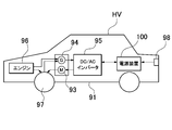
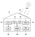
- FIG. 1 It is a schematic plan view of the power supply device including a plurality of battery modules. It is a schematic circuit diagram of the power supply device shown in FIG. It is a block diagram which shows an example which mounts a battery module in a hybrid vehicle which runs by an engine and a motor. It is a block diagram which shows an example which mounts a battery module in an electric vehicle which runs only by a motor. It is a block diagram which shows the example which uses the battery module for a power storage device. It is an exploded perspective view of the conventional battery module.
- a gas duct is arranged on the upper surface of the battery laminate in order to exhaust the exhaust gas ejected from the exhaust valve of the battery cell to the outside.
- the gas duct is provided to exhaust the high-temperature and high-pressure exhaust gas discharged from the exhaust valve of the battery cell to the outside.
- the exhaust valve of the battery cell opens when the internal pressure rises to the set value to prevent the battery case from exploding. This exhaust valve opens when it detects that the internal pressure of the battery becomes abnormally high, but the internal pressure of the battery cell causes overcharging, overdischarging, and an internal short circuit, resulting in a combustion event inside the battery cell.
- the high-temperature and high-pressure exhaust gas ejected from the battery cell has an adverse effect such as burning peripheral members, and is therefore exhausted to the outside through a gas duct.
- the gas duct is arranged on the battery laminate in order to guide the exhaust gas from the exhaust valve of the battery cell to the outside.
- the gas duct is provided with an inflow hole for allowing the exhaust gas ejected from the exhaust valve of each battery cell to flow into the inside.
- the power supply module includes a circuit board on which a voltage detection circuit for detecting the voltage of the battery cells is mounted in order to prevent overcharging or overdischarging of each battery cell.
- the voltage detection circuit provided on the circuit board is connected to the electrode terminals of the battery cells via the voltage detection line and detects the voltage of each battery cell.
- the circuit board is arranged on the upper surface of the battery laminate, and the voltage detection line can be shortened.
- the short voltage detection line has a small line impedance and can accurately detect the cell voltage.
- the gas duct is arranged on the electrode surface of the battery laminate and connected to the exhaust valve of the battery cell
- the circuit board is arranged on the gas duct to form the circuit board.
- the voltage detection circuit can be connected to the battery cell via the voltage detection line.
- a gas duct extending in the stacking direction of the battery cells is arranged on the upper surface of the battery laminate so that the exhaust gas ejected from the battery cells can be smoothly exhausted to the outside, and further, the battery cells can be smoothly exhausted to the outside.
- a circuit board extending in the stacking direction of the above can be arranged, and the voltage detection circuit of the circuit board can be connected to the electrode terminal of the battery cell with a short voltage detection line.
- the high-temperature and high-pressure exhaust gas ejected from the battery cell has an adverse effect such as burning the circuit board.
- the electronic components of the voltage detection circuit on the circuit board are adversely affected by high-temperature and high-voltage exhaust gas, which reduces safety.
- the connector and lead wire of the voltage detection line are also arranged on the upper surface of the battery laminate, but the high temperature and high pressure exhaust gas burns the connector and lead wire, and the heat of combustion of these burns the battery cell. It causes smoke and fire in a chain reaction, which reduces safety.
- the exhaust gas is abnormally high temperature and high pressure, it is difficult for the gas duct to completely discharge the gas to the outside.
- the circuit board is separated from the terminal surface of the battery cell by the gas duct, the exhaust gas leaking from the gas duct may burn the circuit board and further increase the heat damage. Further, the exhaust gas contains foreign substances such as metal pieces inside the battery cell, which may cause a short-circuit failure of the electronic circuit of the circuit board.
- the battery module is required to be miniaturized as a whole in almost all applications without exception. This is to improve the performance by increasing the charge / discharge capacity with respect to the unit volume.
- the components arranged on the upper surface of the battery laminate include a gas duct for discharging exhaust gas, an electrode terminal protruding from the terminal surface, and a metal plate bus bar for connecting adjacent electrode terminals.
- a battery module in which a large number of parts such as a gas duct, a circuit board, and a lead wire are arranged on the upper surface of a battery laminate cannot be miniaturized by lowering the height of the battery module only by improving the component arrangement.
- the substrate has a detrimental effect of substantially increasing the volume, especially the height, of the battery module.
- the circuit board is made thinner and smaller, the drawback that the thermal energy of the heat-generating components mounted on the circuit board cannot be efficiently dissipated becomes remarkable. Since heat-generating components such as semiconductor elements and discharge resistors are mounted on the circuit board, it is extremely important to efficiently dissipate heat energy and make the temperature rise of the heat-generating components lower than the set temperature.
- the power supply module described in the following embodiment can eliminate the above drawbacks due to its unique structure.
- the battery module of the first embodiment of the present invention includes a battery laminate formed by stacking a plurality of battery cells, a pair of end plates arranged at both ends of the battery laminate in the stacking direction, and a pair of ends. It includes a bind bar connecting plates and an electronic circuit block on which a voltage detection circuit for detecting the voltage of a battery cell is mounted.
- the electronic circuit blocks are arranged on the outer surfaces of both end plates arranged at both ends of the battery laminate, and each electronic circuit block is connected to the battery cell via a voltage detection line.
- the above battery module can reduce the size of the battery module and increase the charge / discharge capacity with respect to the unit volume while protecting the circuit board from the high-temperature and high-pressure exhaust gas ejected from the exhaust valve of the battery cell, and further, the voltage detection circuit.
- the advantage is that the thermal energy of the electronic circuit block to be mounted can be efficiently dissipated to the end plate and the outside, and the temperature rise of the electronic circuit block can be reduced.
- the above structure has a feature that since the electronic circuit block can be arranged on the surface of the end plate in a vertical posture, air can convection smoothly on the surface of the electronic circuit block and heat can be efficiently dissipated.
- the electronic circuit block which is the end plate and is shielded from high-temperature and high-pressure exhaust gas, ensures high safety as a normal operating state even in an abnormal use state of the battery cell in which the exhaust valve is opened.
- the characteristic of being able to efficiently dissipate the heat energy of the electronic circuit block also realizes the feature that the temperature rise can be reduced while the electronic circuit block is miniaturized.
- the temperature rise of the electronic components mounted on the electronic circuit block is also reduced, and the stable operation of the electronic components can be guaranteed.
- the electronic circuit blocks are arranged on both end plates arranged at both ends of the battery laminate, that is, the electronic circuit blocks are divided into two sets and arranged on the end plates.
- the voltage detection line connecting the cell and the electronic circuit block can be shortened. This is because each battery cell can be connected to a nearby electronic circuit block via a voltage detection line. Being able to shorten the voltage detection line is extremely important for detecting the voltage of the battery cell with higher accuracy. This is because a long voltage detection line has a high impedance and is easily affected by noise, and the voltage drop is also large, and the noise and the voltage drop cause a detection error of the cell voltage. Since the detection accuracy of the cell voltage affects the deterioration and life of the battery module, it is extremely important how highly accurate it can be detected.
- the electronic circuit block is arranged on the outer surface of the end plate without arranging the electronic circuit block on the electrode surface of the battery laminate, the high temperature and high pressure ejected from the battery cell while designing the whole low.
- the electronic circuit block can be protected from exhaust gas.
- the end plate is arranged between the battery laminate and the electronic circuit block, this end plate can block the electronic circuit block from the exhaust gas of the battery cell and protect the electronic circuit block from the exhaust gas of high temperature and high pressure. Therefore, even in an abnormal state, the normal operation of the electronic circuit block is guaranteed and high safety is guaranteed.
- the voltage detection line connecting the battery cell and the electronic circuit block is shortened to lower the impedance of the line, and particularly to reduce the electrical resistance. It also realizes the feature that the voltage of each battery cell can be detected with high accuracy by making it smaller. Further, since the heat generated by the electronic circuit block can be efficiently dissipated to the end plate, the temperature rise of the electronic circuit block can be reduced. Furthermore, since the electronic circuit block can be arranged on the surface of the end plate in a vertical position, air can be smoothly convected on the surface of the electronic circuit block to improve the cooling efficiency.
- the structure that can efficiently dissipate heat from the electronic circuit block makes the temperature rise locally small even if the electronic circuit block is miniaturized and the heat generation is concentrated in a narrow area, and the temperature of the electronic component that generates heat in the electronic circuit block. The rise is also small, and more stable operation can be guaranteed.
- a battery laminate composed of a plurality of battery cells is divided into a plurality of battery units in the middle of the stacking direction of the battery cells, and each battery unit has a voltage detection line. It is connected to separate electronic circuit blocks via.
- the battery module according to the third embodiment of the present invention includes a gas duct in which the battery laminate is connected to an opening of an exhaust valve provided in the battery cell, and the gas duct is provided at the center of the electrode surface of the battery laminate.
- the battery cells are arranged so as to extend in the stacking direction, and the voltage detection line is arranged along the side edge of the gas duct.
- the above battery module can reduce the wiring space of the voltage detection line, it has the advantage that the width of the gas duct arranged on the electrode surface can be widened to smoothly exhaust the exhaust gas and prevent gas leakage.
- the reason why gas leakage can be prevented and safety can be ensured is that the increase in internal pressure of the gas duct is reduced.
- the wiring space of the voltage detection line can be reduced because the voltage detection line can be branched into two sets of electronic circuit blocks and wired to reduce the number of voltage detection lines connected to each electronic circuit block. ..
- voltage detection lines are arranged on both sides of the gas duct.
- the above battery modules have the advantage that the wiring space on both sides of the gas duct can be further reduced because the voltage detection lines connected to each electronic circuit block can be separated and wired on both sides of the gas duct.
- the electronic circuit block includes a cell balance adjusting circuit for adjusting the cell balance of each battery cell, and the cell balance adjusting circuit energizes the voltage detection line for each. Adjust the cell balance of the battery cell.
- each battery cell can be quickly cell-balanced by using the voltage detection line together for cell balance adjustment. This is because the cell-balancing voltage detection line can be shortened and the electrical resistance can be reduced by connecting it to a nearby electronic circuit block. By shortening the voltage detection line and reducing the electrical resistance, the voltage drop in the wiring during cell balance is reduced, and the voltage detection accuracy is improved.
- the voltage detection line is a wire harness or a printed circuit board.
- the printed circuit board of the voltage detection line is a flexible printed circuit board (FPC).
- the above battery module can be connected to an electronic circuit block in which the voltage detection line is divided into two and arranged nearby, the voltage detection line can be shortened, and the flexible printed circuit board can be shortened for mass production at low cost.
- the battery module of the eighth embodiment of the present invention includes a communication terminal capable of transmitting a signal by cascading a plurality of electronic circuit blocks in an electronic circuit block, and cuts off a direct current to transmit an AC signal to the communication terminal. It is internally connected via a coupling element that is passed through.
- the communication terminals of the above battery modules are internally connected via a coupling element, they have the advantage of being able to connect to other communication terminals and transmit signals without adjusting to the DC level. This is particularly effective in a device in which a plurality of battery modules are connected in series.
- a potential difference is generated in the ground line of each battery module. Since the communication terminal of the electronic circuit block transmits a signal with the ground line as the reference potential, the communication terminal having a potential difference in the ground line applies a bias voltage to shift the DC level of the ground line and is connected to the communication terminal.
- the potential difference of the ground line needs to be set to zero level, but this circuit configuration becomes considerably complicated.
- the ground line changes stepwise, so that equalizing the ground lines with a plurality of bias voltages becomes an extremely complicated circuit configuration. Furthermore, since the bias voltage that equalizes the ground lines shifts with temperature, it is necessary to control the temperature characteristics extremely accurately, and the circuit configuration becomes more complicated. In the above battery modules, it is not necessary to equalize the DC level of the ground line with the bias voltage, and a large number of battery modules are connected in series and the communication terminals of the battery modules having a potential difference are easily connected to the ground line for signals. Has the feature of being able to transmit.
- the coupling element is any one of a coupling capacitor, a transformer, and a photoelectric transmission element.
- the power supply device is a power supply device including a plurality of the above battery modules, in which adjacent battery modules are connected to a power line by an external communication line, and the power line is connected to an output terminal of the battery module. Connected, the external communication line is connected to the communication terminal, the external communication line is connected to the communication terminal located at the end of the battery module which is connected to the power line, and both the power line and the external communication line are connected. , Connected to the same end of the battery module.
- an external communication line is connected to a pair of communication terminals in which battery modules arranged adjacent to each other are arranged closest to each other.
- the battery modules shown in the following examples are mainly suitable for powering electric vehicles such as hybrid cars and plug-in hybrid cars that run on both engines and motors, electric vehicles that run only on motors, and electric bikes that run on motors. Is.
- the battery module of the present invention is also suitable as a power source for a power storage device other than an electric vehicle, which requires a large output.
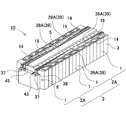
- the battery modules 10 shown in FIGS. 1 to 4 are arranged at both ends of the battery laminate 2 in which a plurality of battery cells 1 are laminated in the thickness direction and the battery cells 1 of the battery laminate 2 in the stacking direction.
- the battery module 10 shown in the figure is arranged above the gas duct 5 connected to the opening of the exhaust valve 1a provided in each battery cell 1 and above the battery laminate 2 and above the gas duct 5.
- the cover case 8 is provided with a cover case 8 and a base plate 9 arranged below the battery laminate and fixing the end plate 3.
- the battery cell 1 is a rectangular secondary battery having a width wider than the thickness, in other words, a square secondary battery thinner than the width, and is laminated in the thickness direction to form a battery laminate 2.
- the battery cell 1 is a lithium ion secondary battery.
- the battery cell can be any other rechargeable secondary battery, such as a nickel metal hydride battery or a nickel cadmium battery.
- positive and negative electrode plates are housed together with an electrolytic solution in an outer can having a closed structure.
- the outer can is made by press-molding a metal plate such as aluminum or an aluminum alloy into a square shape, and the opening is hermetically sealed with a sealing plate.
- the sealing plate is made of the same aluminum or aluminum alloy as the outer can, and the positive and negative electrode terminals 11 are fixed, and an exhaust valve is provided between the electrode terminals 11.
- the positive and negative electrode terminals 11 are in a state in which at least one of the electrode terminals 11 is insulated from the sealing plate.
- the battery cell 1 is provided with positive and negative electrode terminals 11 with the sealing plate as the terminal surface 1X. Further, in the battery cell 1, the bottom surface and the side surface of the outer can are covered with an insulating film.
- the plurality of battery cells 1 are laminated so that the thickness direction of each battery cell 1 is the stacking direction to form the battery laminate 2.
- the plurality of battery cells 1 are laminated so that the terminal surfaces 1X provided with the positive and negative electrode terminals 11 are arranged on the same plane to form the electrode surfaces 2X to form the battery laminate 2.
- the battery laminate 2 has an insulating spacer 12 sandwiched between the stacked battery cells 1.
- the insulating spacer 12 in the figure is made of an insulating material such as resin in the form of a thin plate or sheet.
- the insulating spacer 12 shown in the figure has a plate shape having a size substantially equal to the facing surface of the battery cells 1, and the insulating spacers 12 are laminated between the battery cells 1 adjacent to each other to connect the adjacent battery cells 1 to each other. Insulated.
- a spacer having a shape in which a flow path of a cooling gas is formed between the battery cell and the spacer can also be used.
- a metal bus bar 14 is connected to the positive and negative electrode terminals 11 of the adjacent battery cells 1, and a plurality of battery cells 1 are connected in series or in parallel, or in series and in parallel by the bus bar 14. ing.
- the output voltage and the capacity that can be charged and discharged are set values depending on the number of battery cells 1 to be stacked.
- the output voltage can be increased by the number of battery cells 1 connected in series, and the charge / discharge capacity can be increased by the number of battery cells 1. Since the battery module 10 sets the output voltage and the capacity as set values in a connected state in which the number of battery cells 1 constituting the battery laminate 2 and the battery cells 1 are connected in series with each other, the number of battery cells 1 and the connected state are used. It is considered to be the optimum state in consideration of.
- the bus bar 14 is provided with a connection portion (not shown) for connecting to the electrode terminal 11.
- the bus bar 14 is connected by irradiating a boundary connecting the connection portion and the electrode terminal 11 with a laser beam and welding the connection portion to the electrode terminal 11.
- the bus bar is provided with a male screw on the electrode terminal to open a through hole for inserting the electrode terminal, and a nut is screwed into the male screw of the electrode terminal inserted through the through hole to connect to the electrode terminal.
- the electrode terminal may be provided with a female screw hole, and a set screw penetrating the bus bar may be screwed into the female screw hole to connect to the electrode terminal.
- the battery module 10 may be provided with a resin insulating cover (not shown) on the upper surface of the battery laminate 2.
- the insulating cover is provided with an opening, and the electrode terminal 11 is exposed from the opening, and a metal plate bus bar 14 is connected to the electrode terminal 11 exposed from the opening of the insulating cover on the upper surface side of the insulating cover.
- a plurality of battery cells 1 can be connected in a predetermined arrangement.
- End face spacer 13 In order to insulate the battery laminate 2 from the metal end plate 3, the end plates 3 can be arranged on both end faces with the end face spacers 13 interposed therebetween.
- the end face spacer 13 is arranged between the battery laminate 2 and the end plate 3 to insulate the end plate 3 from the battery laminate 2.
- the end face spacer 13 is made of an insulating material such as resin in the form of a thin plate or sheet.
- the end face spacer 13 is provided with a plate portion having a size capable of covering the entire facing surface of the battery cell 1, and this plate portion is laminated between the battery cell 1 and the end plate 3 arranged at both ends of the battery laminate 2. is doing.
- End plate 3 The end plates 3 are on both end faces of the battery stack 2 in the stacking direction of the battery cells 1 and fix the battery stack 2.
- the end plate 3 is a metal plate, and is a quadrangular plate whose outer shape is substantially equal to the outer shape of the battery cell 1 or slightly larger than that of the battery cell 1.
- the end plate 3 can be manufactured of a high-strength rope to have a tough structure.
- the end plate 3 may be a single metal plate, a structure in which a plurality of metal plates are laminated, or a laminate of a metal plate and plastic.
- the end plate 3 made of one metal plate has a large heat capacity and can efficiently absorb the heat energy of the electronic circuit block 6.
- the surface side on which the electronic circuit block 6 is fixed is at least a metal plate material. This is because the electronic circuit block 6 is fixed in a heat-coupled state to improve heat dissipation characteristics.
- the end plate 3 can have a laminated structure of an aluminum plate and a high-strength rope plate. This end plate has a structure in which an electronic circuit block is fixed with the surface side as an aluminum plate, and the aluminum plate and the high-strength rope plate are laminated in a surface contact state so that heat can be efficiently conducted from the aluminum plate to the high-tensile rope plate. You can also do it.
- the end plate is not necessarily made of metal, but may be made of plastic having excellent strength such as engineering plastic.
- the bind bar 4 extends in the stacking direction of the battery cells 1 and fixes both ends thereof to the end plates 3, and the battery stack 2 is fixed by the pair of end plates 3.
- the bind bar 4 shown in FIGS. 1 and 2 is a metal plate having a predetermined vertical width and a predetermined thickness along the side surface of the battery laminate 2, and is arranged so as to face both side surfaces of the battery laminate 2. ..
- the bind bar 4 presses both end surfaces of the battery laminate 2 with a strong pressure to charge and discharge the battery cell 1 to expand, and arranges the battery cells 1 at a fixed position.
- As the metal plate of the bind bar 4 a high-strength rope is preferably used.
- the bind bar 4 of the metal plate is press-molded to form a predetermined shape.
- the bind bar 4 has both ends of the battery laminate 2 on the outer surface of the end plate 3 at both ends in the stacking direction in order to fix both ends to the pair of end plates 3.
- the fixing portion 4A is provided by bending along the above.
- the bind bar 4 fastens the pair of end plates 3 by screwing the fixing portion 4A into the end plate 3.
- the bind bar 4 is formed by bending the lower end portion into an L shape to form the lower connecting piece 4B.
- the lower connecting piece 4B is laminated on the lower surface side of both side portions of the base plate 9 and connected to the base plate 9.
- the bind bar 4 is formed by bending the upper end portion to form a pressing piece 4C that presses the upper end portion of the upper surface of the battery laminate 2.
- the pressing piece 4C is separated for each battery cell 1 so that the upper surface of the battery cell 1 of the battery stack 2 can be individually pressed. As a result, each pressing piece 4C can press the battery cell 1 toward the base plate 9 independently of the adjacent pressing piece 4C.
- each battery cell 1 is prevented from rising from the base plate 9 and held in the height direction, and even if vibration, impact, or the like is applied to the battery laminate 2, each battery cell 1 is positioned in the vertical direction. It can be maintained so that it does not shift.
- the bind bar 4 covers and holds the corners of the upper and lower surfaces of the battery laminate 2 on both the left and right sides of the battery laminate 2.
- both ends of the bind bar may be formed into a flat plate shape without being bent into an L shape, and may be configured to be screwed with the side surface of the end plate.
- an engaging structure in which the portion of the bind bar facing the side surface of the end plate is engaged in a stepped shape as a structure in which the bind bar is further screwed in a state of being locked to the side surface of the end plate with a locking structure. May be good.
- an insulating sheet may be interposed between the bind bar 4 and the battery laminate 2.
- the insulating sheet is made of a material having an insulating property, for example, resin, and insulates between the metal bind bar 4 and the battery cell 1.
- the base plate 9 is arranged on the bottom surface of the battery laminate 2 and the end plate 3.
- the end plate 3 is fixed to the base plate 9, and more preferably, the lower end portion of the bind bar 4 is also fixed to the base plate 9.
- the end plate 3 and the bind bar 4 are fixed to the base plate 9 via the fixing screws 15 and 16.
- the fixing screw 15 for fixing the end plate 3 penetrates the end plate 3 in the vertical direction and fixes the end plate 3 to the base plate 9.
- the fixing screw 16 for fixing the bind bar 4 also penetrates the lower connecting piece 4B which is the lower end portion of the bind bar 4 and is fixed to the base plate 9.
- the battery laminate 2 is arranged in a heat-bonded state with the base plate 9 by bringing each battery cell 1 into contact with the base plate 9.
- the base plate 9 can be forcibly cooled to dissipate the heat energy of the battery cell 1 more efficiently.
- the base plate 9 to be forcibly cooled can be forcibly cooled by circulating a refrigerant or a coolant inside.
- the base plate can be forcibly cooled by providing heat radiation fins on the lower surface.
- a cooling plate can be laminated on the lower surface of the base plate in a surface contact state, and forced cooling can be performed by the cooling plate.
- the cooling plate can be forcibly cooled by circulating a refrigerant or a coolant inside.
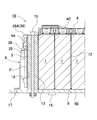
- the gas duct 5 As shown in FIGS. 3 and 4, the gas duct 5 is arranged at a position facing the upper surface of the battery cell 1, that is, the terminal surface 1X of the battery cell 1, and exhausts the exhaust gas ejected from the exhaust valve 1a to the outside. do.
- the gas duct 5 shown in FIG. 4 is arranged at the center of the electrode surface 2X of the battery stack 2 in a posture extending in the stacking direction of the battery cells 1.
- the gas duct 5 has a tubular shape having an internal volume that smoothly discharges the discharged material discharged from the opening of the exhaust valve 1a, opens the lower surface, and is connected to the opening of the exhaust valve 1a of each battery cell 1. There is.
- the gas duct 5 is formed on the upper surface of the battery laminate 2 so that the exhaust gas discharged from the exhaust valve 1a is exhausted to the outside so that there is no gap between the gas duct 5 and the terminal surface 1X of the battery cell 1.
- An opening 5a that is arranged in close contact with the upper surface and opens on the lower surface is connected to the exhaust valve 1a of each battery cell 1.
- the gas duct 5 may be arranged so that exhaust gas does not leak by arranging packing, a sealing material, or the like between the gas duct 5 and the terminal surface 1X.
- the gas duct is a collecting duct arranged on the upper surface of the battery stacking body in a posture extending in the stacking direction of the battery cells, and a branch duct connected to the collecting duct and the tip is connected to the exhaust valve. It can also be configured with.
- the collecting duct can be arranged away from the terminal surface, and the tip of the branch duct can be connected to the opening of the exhaust valve.
- the battery module 10 of FIGS. 2 and 4 includes two sets of electronic circuit blocks 6.
- the two sets of electronic circuit blocks 6 are fixed to the outer surfaces of both end plates 3 which pressurize and fix the battery laminate 2 from both ends.
- the two sets of electronic circuit blocks 6 include a voltage detection circuit 22 that detects the voltage of the battery cell 1.
- the voltage detection circuit 22 of each electronic circuit block 6 is connected to each battery cell 1 via a voltage detection line 19 to detect the voltage of the battery cell 1.
- the battery module 10 in which the electronic circuit block 6 is divided into two sets and arranged on the end plate 3 can connect the voltage detection line 19 to the battery cell 1 and the nearby electronic circuit block 6, and is therefore shown in FIG. 6 as a reference example.
- the voltage detection line 19 can be shortened as compared with the battery module 70 including one set of electronic circuit blocks 6.
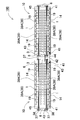
- the battery module 10 of FIG. 4 is divided into two sets of battery units 2A in the middle of the stacking direction of the battery cells 1, and the battery cells 1 of each battery unit 2A are divided into separate electronic circuit blocks via the voltage detection line 19. It is connected to 6.
- the battery module 10 that divides the battery laminate 2 into two at the center can shorten the longest voltage detection line 19 to 1/2 the length of the battery module including the set of electronic circuit blocks 6 shown in FIG. ..
- voltage detection lines 19 are wired on both sides of the gas duct 5 along the side edges of the gas duct 5.
- the battery module 10 can reduce the number of voltage detection lines 19 wired on both sides of the gas duct 5 to narrow the wiring space of the voltage detection lines 19.
- the voltage detection line 19 having a narrow wiring space can widen the width of the gas duct 5 arranged at the center thereof to smoothly exhaust the exhaust gas and prevent gas leakage.
- the plurality of voltage detection lines 19 are wired on the upper surface of the battery laminate 2 as a wire harness or a printed circuit board 39.
- the battery module 10 in which the printed circuit board 39 of the voltage detection line 19 is a flexible printed circuit board 39A (FPC) has a feature that the wiring space of the voltage detection line 19 can be made extremely thin.
- the electronic circuit block 6 shown in FIGS. 2, 4 and 7 includes a connection terminal 37 for connecting a voltage detection line 19 which is a flexible printed circuit board 39A.
- the flexible printed circuit board 39A shown in the figure is provided with a connector 38 for connecting to the electronic circuit block 6 at one end, and by connecting this connector 38 to the connection terminal 37 provided in the electronic circuit block 6, it is easy and reliable. It is possible to connect.
- the electronic circuit block 6 shown in the figure has a thin box shape so that the entire outer shape can be arranged along the outer surface of the end plate, and the connection terminals 37 for connecting the connectors 38 to both ends of the upper surface thereof. Is provided.
- connection terminal 37 can be conveniently wired at a position where it does not interfere with the gas duct 5.
- connection terminal may be arranged at the center of the upper surface of the box-shaped electronic circuit block. In this case, by bending the tip of the voltage detection line (flexible printed circuit board) connected to the connection terminal in a crank shape, the main body of the voltage detection line (flexible printed circuit board) is connected to the connection terminal. Can be wired on both sides of the gas duct.
- the electronic circuit block 6 mounts an electronic component that realizes the voltage detection circuit 22 on the circuit board 20 (see FIGS. 5 and 8).
- the electronic circuit block 6 may be a block in which all the electronic circuits including the voltage detection circuit 22 are integrated circuits and the integrated circuits are embedded in a package of an insulating material.
- the electronic circuit block 6 can be a block in which the metal plate of the radiator 21 is arranged on the surface.
- the radiator 21 is thermally coupled to heat-generating components built in the electronic circuit block 6, for example, a semiconductor element such as a FET that controls the discharge resistance and current of the cell balance adjustment circuit, and heat energy of these heat-generating components. Dissipate heat to the outside.
- the electronic circuit block 6 has an electronic component mounted on a circuit board 20 to form a plate shape as a whole, or an integrated circuit embedded in a package to form a plate shape.
- the electronic circuit block 6 including the voltage detection circuit 22 detects the voltage of the battery cell 1 whose voltage fluctuates due to charging / discharging, and sets the battery voltage as a set range to prevent overcharging or overdischarging of each battery cell 1. ..
- the battery module 10 may include a control circuit 30 for controlling the charge / discharge current of the battery stack 2 in the electronic circuit block 6.
- the control circuit 30 controls the charging / discharging current to prevent overcharging and overdischarging of the battery cell 1.
- the voltage detection circuit 22 transmits the voltage data of the battery cell 1 to the control circuit 30.
- the electronic circuit block can also transmit battery information to an external control circuit without providing a control circuit, and control the charging / discharging current of the battery module 10 with the external control circuit.
- the voltage detection circuit 22 preferably detects the voltage of all the battery cells 1. However, the voltage detection circuit 22 does not necessarily detect the voltage of all the battery cells 1.
- the battery cell 1 constituting the battery laminate 2 is divided into a plurality of battery units, and the voltage of each battery unit is divided. Can also be detected.
- a battery unit in which a plurality of battery cells 1 are connected in parallel can detect the voltage of the battery unit and detect the voltage of all the battery cells.
- the battery unit in which a plurality of battery cells are connected in series detects the voltage of the battery unit and detects the total voltage of the battery cells connected in series.
- a battery unit in which a plurality of battery cells are connected in series is composed of 2 to 5 battery cells.
- this battery unit detects the voltage of the battery unit and detects the total voltage of 2 to 5 battery cells 1, the voltage of the battery cells is 1/2 to 1/5 of the detected total voltage.
- the voltage of the battery cell 1 changes with the remaining capacity.
- the voltage of the battery cell 1 becomes higher than the preset maximum voltage when it is overcharged, and becomes lower than the minimum voltage when it is overdischarged.
- the voltage detection circuit 22 detects the voltage of the battery cell 1 and transmits it to the control circuit 30, and the control circuit 30 controls the charging / discharging current so that the voltage of the battery cell 1 is within the set range.
- the battery module 10 As the battery module 10 is repeatedly charged and discharged, the remaining capacity and voltage of each battery cell 1 become unbalanced.
- the battery cells 1 connected in series are charged and discharged with the same current. Although they are charged and discharged with the same current, the electrical characteristics of each battery cell 1 are not completely the same. Therefore, in the battery module 10 in which a plurality of battery cells 1 are connected in series, the voltage and the remaining capacity of each battery cell 1 become unbalanced as charging and discharging are repeated.
- An imbalance in the battery cell 1 causes the specific battery cell 1 to be overcharged or overdischarged. Since the battery module 10 charges and discharges all the battery cells 1 at the same time, the imbalance of the battery cells 1 causes the specific battery cells 1 to be overcharged or overdischarged. Overcharging and overdischarging of the battery cell 1 deteriorates the electrical characteristics of the battery cell 1 and causes deterioration, and also reduces the safety of the battery module 10.
- the cell balance adjustment circuit 23 eliminates the imbalance of the voltage of
- the electronic circuit block 6 also mounts a cell balance adjusting circuit 23 that equalizes the voltage of the battery cell 1.
- the cell balance adjustment circuit 23 uses the voltage detection line 19 to discharge the high voltage battery cell 1 and charge the low voltage battery cell 1 to equalize the voltage of the battery cell 1 and unbalance it. Eliminate.
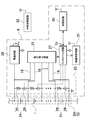
- An example of the circuit diagram of the cell balance adjustment circuit 23 is shown in FIG. Since the voltage of the battery cell 1 having a large remaining capacity is high, the battery cell 1 having a high voltage can be discharged to equalize the remaining capacity.
- the cell balance adjustment circuit 23 shown in this figure discharges the battery cell 1 having a high voltage with the discharge resistor 25 to eliminate the imbalance. However, the cell balance adjustment circuit 23 is not specified as a circuit that discharges the battery cell 1 with the discharge resistance 25.
- a battery cell having a high voltage is discharged to a power storage device such as a capacitor or a storage battery to store the battery in the power storage device, and the charge of the storage device is discharged to a battery cell having a low voltage to discharge the voltage of the battery cell.
- a power storage device such as a capacitor or a storage battery to store the battery in the power storage device
- the charge of the storage device is discharged to a battery cell having a low voltage to discharge the voltage of the battery cell.
- the cell balance adjustment circuit can also convert the voltage of a high voltage battery cell with a DC / DC converter and charge the low voltage battery cell while controlling the current to equalize the voltage.
- the cell balance adjustment circuit 23 of FIG. 5 includes a discharge circuit 24 in which a switching element 26 is connected in series to the discharge resistor 25, detects each cell voltage, and controls the switching element 26 to be ON / OFF.
- the circuit 27 and the voltage detection circuit 22 that detects the cell voltage of each battery cell 1 are connected.
- the discharge resistor 25 and the discharge circuit 24 of the switching element 26 are connected in parallel with each battery cell 1.
- the cell balance adjusting circuit 23 switches the switching element 26 to ON by the control circuit 27, discharges the battery cell 1 with the discharge resistor 25, and causes the voltage of the battery cell 1 to be discharged. To reduce and equalize.
- the cell balance adjustment circuit 23 is driven by receiving electric power from the battery laminate 2.
- the cell balance adjustment circuit 23 in the figure is operated by the output voltage (Vcc) of the power supply circuit 28 that receives power from the battery stack 2.
- the voltage of the battery laminate 2 can be stepped down by, for example, a DC / DC converter which is a power supply circuit 28, and supplied to the cell balance adjustment circuit 23. According to this circuit configuration, even if the voltage of the battery laminate 2 is high, it can be supplied to the cell balance adjusting circuit 23 as an optimum voltage.
- the control circuit 27 compares the cell voltages of the respective battery cells 1 and controls the switching element 26 so as to equalize the cell voltages of all the battery cells 1.
- the control circuit 27 switches the switching element 26 of the discharge circuit 24 connected to the battery cell 1, which is too high, to ON to discharge the battery.
- the voltage of the battery cell 1 decreases as it is discharged.
- the switching element 26 is switched from ON to OFF when the voltage of the battery cell 1 drops until it is balanced with the other battery cells 1.
- the control circuit 27 discharges the battery cell 1 having a high cell voltage to balance the cell voltages of all the battery cells 1.
- the cell balance adjustment circuit 23 described above equalizes the voltages of all the battery cells 1, but the battery module divides all the battery cells into a plurality of battery units and sets the voltage of the battery cells constituting the battery units as cell cells. After equalizing with the balance adjustment circuit, the voltage of the entire battery unit can be equalized with the unit cell balance adjustment circuit.
- the unit cell balance adjustment circuit detects the unit voltage of each battery unit, discharges the battery unit having a high unit voltage, and equalizes the voltage of each battery unit.
- the electronic circuit block 6 is fixed to the end plate 3 and dissipates heat to the end plate 3.
- the electronic circuit block 6 includes a semiconductor element such as an FET that controls a current and a heat generating element such as a discharge resistor.
- the electronic circuit block 6 can dissipate the heat energy of the heat generating element to the end plate 3 to reduce the temperature rise.
- the temperature rise of the electronic circuit block 6 adversely affects the built-in heat generating element and the like.
- the cell balance adjustment circuit 23 discharges the battery cell 1 with the discharge resistor 25 to lower the voltage, but the discharge resistor 25 generates heat due to the Joule heat of the discharge current.
- the discharge resistor 25 can increase the current and quickly reduce the voltage of the battery cell 1 in a short time, but the Joule heat that heats the discharge resistor 25 increases in proportion to the square of the discharge current, so that the voltage can be rapidly reduced.
- the cell balance adjustment circuit 23, which can reduce the voltage of the battery cell 1 to shorten the equalization time, generates a large amount of heat energy. Since the cell balance adjusting circuit 23 equalizes the battery cells 1 at the timing when the battery cells 1 are not charged or discharged, the equalization time is required to be shorter. Since the reduction of the equalization time can be realized by increasing the current of the discharge resistor 25, how efficiently the heat generation energy of the discharge resistor 25 can be dissipated is an important factor for specifying the equalization time.
- the temperature rise due to the heat generation energy of the heat-generating parts leads to the failure of the parts, it is designed to increase the overall temperature so that the heat-generating parts do not rise abnormally, or to reduce the amount of heat generated per unit time such as discharge resistance. Will be done.
- the electronic circuit block 6 is miniaturized so that it can be arranged in a narrow space, the heat radiation area is reduced, the heat radiation energy is reduced, and the temperature rise is large.
- an electronic circuit block that has been miniaturized so that it can be arranged in a small space between a gas duct and a bus bar, such as a conventional battery module has a small heat dissipation area, so that it is necessary to reduce heat dissipation energy.
- the electronic circuit block arranged in a narrow space needs to reduce the heat radiation energy, and the time for equalizing the battery cells becomes long.
- Battery modules in which a large number of battery cells are stacked are used for large-capacity applications such as battery modules for driving vehicle motors and power storage devices, so the capacity of battery cells is also considerable. big.
- the capacity imbalance due to the battery cell voltage imbalance increases relatively as the battery cell capacity increases. Therefore, this type of battery module is capable of increasing the discharge current because the equalization time of the battery cells is shortened as much as possible and equalized quickly, but the increase in the discharge resistance increases the heat generation energy. Therefore, it is required to increase the heat dissipation area.
- the electronic circuit block is required to be miniaturized in order to be arranged in a narrow space, and it is necessary to increase the heat dissipation area and increase the size in order to discharge with a large current and shorten the equalization time. For this reason, in an electronic circuit block, miniaturization and shortening of equalization time are mutually contradictory characteristics, and both characteristics cannot be satisfied, and miniaturization required for arranging in a limited space is achieved. However, there is a need for issues that contradict the increase in size in order to have high discharge capacity.
- the end plate 3 has an extremely large heat capacity, a small temperature rise with respect to the heat energy to be absorbed, and the equalization time of the battery cell 1 can be shortened.
- the end plate 3 has a large surface area and a large amount of heat radiation energy from the surface, which also makes the temperature rise small. Further, in the structure in which the end plate 3 is fixed to the base plate 9, heat energy is conducted from the end plate 3 to the base plate 9, and the temperature rise is further reduced.
- the end plate 3 is forcibly cooled by the base plate 9, the temperature rise is further reduced, and the cooling effect of the electronic circuit block 6 is further increased. Therefore, the temperature rise of the electronic circuit block 6 is reduced to an ideal state.
- the electronic circuit block 6 is fixed to the outer surface of the end plate 3.
- the battery module 10 has a feature that heat generation energy of an electronic circuit block 6 can be conducted to a fixed end plate 3 to dissipate heat, and heat can be dissipated from an exposed surface to the outside air more efficiently.
- the outer shape of the electronic circuit block 6 fixed to the surface of the end plate 3 is smaller than the outer shape of the end plate 3, and does not protrude from the outer peripheral edge of the end plate 3.
- the electronic circuit block 6 does not increase the outer shape of the battery module 10, and the electronic circuit block 6 can efficiently dissipate heat while being miniaturized.
- the thickness of the electronic circuit block 6 is set so as not to protrude from the tip edge of the base plate 9 to the outer surface in a plan view.
- the outer shape in a plan view is not larger than that of the base plate 9, and the electronic circuit block 6 can be arranged at an ideal position while reducing the overall size.
- the end plate 3 is pressed from the inside with a strong pressure by the battery cell 1 which shows physical properties that expand when charged and discharged.
- the end plate 3 which is pressed by the battery laminate 2 and whose both side edges are fixed by the bind bar 4 is curved by the pressure of the battery laminate 2. If the electronic circuit block 6 is deformed by the curved end plate 3, the components of the electronic circuit block 6 are adversely affected. For example, in the electronic circuit block 6 in which electronic components are fixed to the circuit board, adverse effects such as bending of the circuit board and damage to the conductive portion occur.
- a part of the upper edge portion preferably the central portion, is locally fixed to the end plate 3, and the lower portion is fixed to the tip end portion of the base plate 9.
- the deformation does not adversely affect the electronic circuit block 6.
- the battery module 10 since a part of the upper edge portion of the electronic circuit block 6 is locally fixed to the end plate 3, the battery module 10 does not deform together even if the end plate 3 is curved. Further, since the lower portion of the electronic circuit block 6 is fixed to the tip end portion of the base plate 9, the upper portion and the lower portion are securely fixed to each other. That is, the electronic circuit block 6 is firmly fixed to the end plate 3 and the base plate 9 without being adversely affected by the deformation of the end plate 3.
- the battery module 10 for fixing the electronic circuit block 6 to the base plate 9 arranges the electronic circuit block 6 at a position different from the fixing hole 17 in a plan view, so that the electronic circuit block 6 is fixed to the end plate 3 and the base plate is fixed.
- 9 can be easily and securely fixed to the equipment used such as the chassis of the vehicle.
- the battery module 10 of FIG. 7 is provided with fixing holes 17 on both sides of the base plate 9, and the intervals between the fixing holes 17 are set to a width in which the electronic circuit block 6 can be arranged.
- the electronic circuit block 6 is preferably insulated and fixed to the end plate 3.
- the electronic circuit block 6 is fixed by arranging an insulating sheet 18 between the electronic circuit block 6 and the end plate 3.
- the insulating sheet 18 is an elastic sheet made of a rubber-like elastic body, and can always hold the curved end plate 3 and the electronic circuit block 6 in a heat-bonded state.
- the electronic circuit block 6 insulated and fixed to the end plate 3 is a battery laminate arranged inside the end plate 3 while having a structure in which a metal radiator 21 or the like is exposed on the surface to efficiently dissipate heat. Insulation characteristics can be improved with respect to 2, and reliability can be improved.
- the battery module 10 in which the end plates 3 are arranged on both end surfaces of the battery laminate 2 can prevent electric shock and electric leakage by insulating the end plates 3 from the ground line.
- the end plate 3 insulated from the ground line has a high-voltage battery laminate 2 arranged inside.
- the end plate 3 insulated from the battery laminate 2 has a high leakage resistance with the battery laminate 2, but the leakage resistance may decrease due to various factors. For example, dew condensation water between the end plate 3 and the battery laminate 2 causes a decrease in leakage resistance.
- the electronic circuit block 6 insulated from the end plate 3 is insulated from the end plate 3 even if the contact resistance between the end plate 3 and the battery laminate 2 decreases, thereby preventing adverse effects such as electric leakage and electric shock. To ensure high safety and reliability. However, since the end plate is insulated from the battery laminate, the end plate can also be connected to the ground line.
- the cell balance adjusting circuit 23 Since the above battery module 10 can efficiently dissipate heat generated by the cell balance adjusting circuit 23 of the electronic circuit block 6 by the end plate 3, the cell balance adjusting circuit 23 has a feature that the battery cells 1 can be quickly equalized. This is because the power consumption of the cell balance adjusting circuit 23 can be increased, the battery cell 1 can be discharged with a large current, and the voltage of the high voltage battery cell 1 can be quickly reduced.
- the cell balance adjustment circuit 23 discharges the high-voltage battery cell 1 to eliminate the voltage imbalance, or charges the low-voltage battery cell 1 with the high-voltage battery cell 1 to equalize the voltage.
- the circuit that discharges and equalizes the high-voltage battery cell 1 is a cell balance adjustment circuit 23 that discharges the high-voltage battery cell 1 with the discharge resistance 25 and charges the low-voltage battery cell 1 with the high-voltage battery cell 1. Supply power from the high-voltage battery cell 1 to the low-voltage battery cell 1 to equalize.
- the discharge resistance 25 that discharges the battery cell 1 and the semiconductor element that is the switching element 26 that controls the discharge current of the discharge resistance 25 generate heat.
- This circuit has a structure that efficiently discharges the heat energy of the discharge resistor 25 and the semiconductor element, and can shorten the time for equalizing the discharge current of the discharge resistor 25 and the semiconductor element by increasing the discharge current.
- the discharge can be efficiently discharged and the discharge current can be increased. Further, in the cell balance adjustment circuit that charges the low voltage battery cell with the high voltage battery cell, the semiconductor element that controls the charging current from the high voltage battery cell to the low voltage battery cell generates heat. The current of the element can be increased to shorten the equalization time.
- the electronic circuit block 6 fixed to the end plate 3 is provided with a wireless communication circuit 31, and information such as a battery voltage detected by the voltage detection circuit 22 by the wireless communication circuit 31 is provided. Can be wirelessly transmitted to the central control circuit 33.
- the electronic circuit block 6 does not need to be connected to the central control circuit 33 by a line for external connection, and has a feature that wiring can be easily performed.
- the electronic circuit block 6 can wirelessly transmit information to the central control circuit 33 that controls the traveling motor of the vehicle.
- the battery module having this structure simplifies the complicated wire harness peculiar to the vehicle, prevents the wire harness from having unavoidable adverse effects such as poor contact, and can realize high reliability for a long period of time.
- the electronic circuit block 6 provided with the wireless communication circuit 31 is required to have a characteristic of eliminating a transmission error due to external noise.
- the metal end plate 3 can shield the surface of the electronic circuit block 6 to reduce the influence of external noise.
- the wireless communication circuit 31 can wirelessly transmit information stably and accurately in the end plate 3 provided with the shield convex portion 32 that shields the outer peripheral edge of the electronic circuit block 6 in an integrated structure. Furthermore, by connecting the end plate to the ground line, the shielding effect can be improved and the influence of external noise can be reduced.
- the electronic circuit block 6 includes a communication circuit (not shown) for cascading a plurality of electronic circuit blocks 6 to transmit a signal.
- the communication circuit is connected to the communication terminal 43 via the coupling element 46.
- the communication circuit transmits to the coupling element 46 signals that are alternately transmitted between the detection circuit blocks 6 connected to each other.
- the communication terminal 43 is used as a terminal for connecting the electronic circuit blocks 6 arranged on both sides of the battery module 10, or as a terminal for connecting the electronic circuit blocks 6 of the plurality of battery modules 10. NS.
- the electronic circuit blocks 6 arranged on both sides of one battery module 10 are connected to each other via an internal communication line 45. Further, the electronic circuit blocks 6 of the different battery modules 10 are connected to each other via the external communication line 44.
- the electronic circuit block 6 shown in the figure includes a plurality of communication terminals 43, and these communication terminals 43 have a common terminal structure that can be connected to both the internal communication line 45 and the external communication line 44.
- the electronic circuit block 6 can be provided with a pair of communication terminals 43 on the left and right sides.
- One of the pair of communication terminals 43 is connected to an electronic circuit block having a higher potential, and the other is connected to an electronic circuit block having a lower potential.
- each communication terminal 43 since it is not necessary to consider the potential, each communication terminal 43 has a configuration capable of communicating regardless of whether it is connected to the upper electronic circuit block or the lower electronic circuit block. Therefore, the electronic circuit block 6 having this structure can be connected to the internal communication line 45 or the external communication line 44 while selecting either the left or right communication terminal 43 while being arranged on both sides of the battery module. It has the feature that line wiring can be done efficiently.
- the electronic circuit block 6 shown in the figure is provided with a pair of communication terminals 43 on the left and right sides of the upper surface.
- the pair of communication terminals 43 formed on the upper surface of the electronic circuit block 6 may be provided inside the connection terminals 37 formed at both ends, or, although not shown, outside the connection terminals. It can also be provided.
- the electronic circuit block may be provided with a pair of communication terminals on the left and right side surfaces in place of the upper surface or in addition to the upper surface.
- a large-capacity power supply device 100 can be realized by connecting a plurality of battery modules 10 in series or in parallel with a power line 42.
- the large-capacity power supply device 100 can be effectively used as a power source for an electric vehicle such as a hybrid car or an electric vehicle, and further as a power storage device.
- the power supply device 100 connects the adjacent battery module 10 to the power line 42 by an external communication line 44.
- the power line 42 is connected to the output terminal 41 of the battery module 10 and connects the battery modules 10 in series or in parallel.
- the external communication line 44 is a communication terminal 43 provided in the electronic circuit block 6 and is connected to a communication terminal 43 located at the end of the battery module 10 connected by the power line 42.
- both the power line 42 and the external communication line 44 are connected to the same end of the battery module 10, and the external communication line 44 is connected to the adjacent battery module 10 at the shortest distance. ..
- the end portions on the same side of the battery module 10 mean the ends on the side approaching each other.
- the power supply device 100 includes a plurality of battery modules 10, and each battery module 10 includes two sets of electronic circuit blocks 6.
- all the electronic circuit blocks 6 are cascade-connected.
- all the electronic circuit blocks 6 are connected in cascade, that is, connected in series, so that the signals from all the battery modules 10 are transmitted to the outside by one line. It is possible to transmit signals to the outside separately from each electronic circuit block 6, but since this circuit configuration requires the same number of lines as the number of electronic circuit blocks, it is sent to an external control circuit or the like arranged outside. The signal transmission line becomes complicated.
- the electronic circuit block 6 cascades a plurality of electronic circuit blocks 6 to transmit signals.
- the communication terminal 43 is internally connected via a coupling element 46 that cuts off direct current and allows an AC signal to pass through.
- the coupling element 46 any one of a coupling capacitor, a transformer for signal transmission, and a photoelectric transmission element can be used. Since the electronic circuit block 6 cuts the DC component by the coupling element 46 and transmits only the AC signal to the communication terminal 43, a plurality of electronic circuit blocks do not need to be adjusted by the DC level of the ground line of the communication terminal 43.
- signals can be transmitted by cascading the communication terminals 43 of No. 6. This is particularly effective in an apparatus in which a plurality of battery modules 10 are connected in series.
- the battery module 10 includes two sets of electronic circuit blocks 6, and each electronic circuit block 6 is arranged on end plates 3 provided at both ends of the battery laminate 2.
- the two sets of electronic circuit blocks 6 provided in the battery module 10 are connected by an internal communication line 45, the battery modules 10 arranged adjacent to each other are connected by an external communication line 44, and all the electronic circuit blocks 6 are cascade-connected. Then, the signal is transmitted to the outside by one line.
- the electronic circuit block 6 includes two sets of communication terminals 43, one of the communication terminals 43 is connected to the internal communication line 45, and the electronic circuit blocks 6 on both sides of the battery stack 2 are connected via the internal communication line 45.
- the other communication terminal 43 is connected to the external communication line 44, the electronic circuit blocks of the adjacent battery modules 10 are connected by the external communication line 44, and all the electronic circuit blocks are cascade-connected.
- the pair of communication terminals 43 provided in each electronic circuit block 6 is a common communication terminal 43 that can be connected to both the internal communication line 45 and the external communication line 44.
- the battery module 10 is provided in the two battery modules 10 connected by the power line 42 by connecting the two battery modules 10 arranged closest to each other by the power line 42.
- the communication terminal 43 can be connected to the communication terminal 43 arranged closest to the communication terminal 43 by an external communication line 44.
- the above battery module 10 can be used as a power source for a vehicle that supplies electric power to a motor that runs an electric vehicle.
- an electric vehicle such as a hybrid vehicle or a plug-in hybrid vehicle that runs on both an engine and a motor, or an electric vehicle that runs only on a motor can be used, and is used as a power source for these vehicles. Will be done.
- a large number of the above-mentioned battery modules 10 are connected in series or in parallel, and a large-capacity, high-output power supply device 100 to which a necessary control circuit is added is constructed and mounted. Is preferable.
- FIG. 12 shows an example in which the power supply device 100 is mounted on a hybrid vehicle traveling by both an engine and a motor.
- the vehicle HV equipped with the power supply device 100 shown in this figure is driven by a vehicle main body 91, an engine 96 for running the vehicle main body 91, a running motor 93, and these engines 96 and a running motor 93. It includes wheels 97, a power supply device 100 that supplies electric power to the motor 93, and a generator 94 that charges the batteries of the power supply device 100.
- the power supply device 100 is connected to the motor 93 and the generator 94 via the DC / AC inverter 95.
- the vehicle HV runs on both the motor 93 and the engine 96 while charging and discharging the battery of the power supply device 100.
- the motor 93 is driven to drive the vehicle in a region where the engine efficiency is low, for example, when accelerating or traveling at a low speed.
- the motor 93 is driven by being supplied with electric power from the power supply device 100.
- the generator 94 is driven by the engine 96 or by regenerative braking when braking the vehicle to charge the battery of the power supply device 100.
- the vehicle HV may be provided with a charging plug 98 for charging the power supply device 100. By connecting the charging plug 98 to an external power source, the power supply device 100 can be charged.
- FIG. 13 shows an example in which a power supply device is mounted on an electric vehicle traveling only by a motor.
- the vehicle EV equipped with the power supply device 100 shown in this figure supplies electric power to the vehicle main body 91, the traveling motor 93 for running the vehicle main body 91, the wheels 97 driven by the motor 93, and the motor 93. It includes a power supply device 100 to be supplied and a generator 94 for charging the battery of the power supply device 100.
- the power supply device 100 is connected to the motor 93 and the generator 94 via the DC / AC inverter 95.
- the motor 93 is driven by being supplied with electric power from the power supply device 100.
- the generator 94 is driven by the energy used for regenerative braking of the vehicle EV to charge the battery of the power supply device 100. Further, the vehicle EV is provided with a charging plug 98, and the charging plug 98 can be connected to an external power source to charge the power supply device 100.
- the present invention does not specify the use of the power supply device as a power source for a motor that runs a vehicle.
- the power supply device according to the embodiment can also be used as a power source for a power storage device that charges and stores a battery with electric power generated by solar power generation, wind power generation, or the like.
- FIG. 14 shows a power storage device in which the battery of the power supply device 100 is charged by the solar cell 82 to store electricity.
- the power storage device shown in FIG. 14 charges the battery of the power supply device 100 with the electric power generated by the solar cells 82 arranged on the roof or roof of a building 81 such as a house or a factory.
- This power storage device uses the solar cell 82 as a power source for charging, charges the battery of the power supply device 100 with the charging circuit 83, and then supplies power to the load 86 via the DC / AC inverter 85. Therefore, this power storage device has a charge mode and a discharge mode.
- the DC / AC inverter 85 and the charging circuit 83 are connected to the power supply device 100 via the discharge switch 87 and the charging switch 84, respectively.
- the ON / OFF of the discharge switch 87 and the charge switch 84 is switched by the power controller 88 of the power storage device.
- the power controller 88 switches the charging switch 84 to ON and the discharge switch 87 to OFF to allow the charging circuit 83 to charge the power supply device 100.
- the power controller 88 turns off the charging switch 84 and turns on the discharge switch 87 to switch to the discharge mode, and the power supply device 100 Allows discharge from to load 86.
- the charge switch 84 can be turned on and the discharge switch 87 can be turned on to supply power to the load 86 and charge the power supply device 100 at the same time.
- the power supply device can also be used as a power source for a power storage device that charges and stores batteries using midnight power at night.
- a power supply unit charged with midnight power can be charged with midnight power, which is surplus power of a power plant, and output power in the daytime when the power load is large, so that the peak power in the daytime can be limited to a small value.
- the power supply can also be used as a power source for charging with both solar cell output and midnight power. This power supply device can effectively utilize both the power generated by the solar cell and the midnight power, and can efficiently store electricity while considering the weather and power consumption.
- the above-mentioned power storage devices include a backup power supply device that can be mounted in a computer server rack, a backup power supply device for a wireless base station such as a mobile phone, a power storage power supply for home or factory use, a power supply for street lights, and the like. It can be suitably used for power storage devices combined with solar cells, backup power sources for traffic lights and road traffic indicators, and the like.
- the battery module and power supply device can be suitably used as a power source for a plug-in type hybrid electric vehicle, a hybrid electric vehicle, an electric vehicle, etc. that can switch between an EV driving mode and a HEV driving mode.
- backup power supplies that can be mounted in computer server racks, backup power supplies for wireless base stations such as mobile phones, power storage power supplies for homes and factories, power supplies for street lights, etc. It can also be used as appropriate for backup power supplies.
- Discharge circuit 25 ... Discharge resistance 26 ... Switching element 27 ... Control circuit 28 ... Power supply circuit 30 . Control circuit 31 ... Wireless communication circuit 32 ... Shield convex portion 33 ... Central control circuit 37 ... Connection terminal 38 ... Connector 39 ... Printed board 39A ... Flexible printed board 41 ... Output terminal 42 ... Power line 43 ... Communication terminal 44 ... External communication Line 45 ... Internal communication line 46 ... Coupling element 70 ... Battery module 81 ... Building 82 ... Solar cell 83 ... Charging circuit 84 ... Charging switch 85 ... DC / AC inverter 86 ... Load 87 ... Discharge switch 88 ... Power controller 91 ... Vehicle Main body 93 ... Motor 94 ... Generator 95 ...
Landscapes
- Engineering & Computer Science (AREA)
- Electrochemistry (AREA)
- General Chemical & Material Sciences (AREA)
- Chemical & Material Sciences (AREA)
- Chemical Kinetics & Catalysis (AREA)
- Power Engineering (AREA)
- Manufacturing & Machinery (AREA)
- Transportation (AREA)
- Mechanical Engineering (AREA)
- Sustainable Energy (AREA)
- Sustainable Development (AREA)
- Life Sciences & Earth Sciences (AREA)
- Microelectronics & Electronic Packaging (AREA)
- Aviation & Aerospace Engineering (AREA)
- Battery Mounting, Suspending (AREA)
- Secondary Cells (AREA)
Priority Applications (4)
| Application Number | Priority Date | Filing Date | Title |
|---|---|---|---|
| EP20916065.4A EP4095979B1 (en) | 2020-01-23 | 2020-09-15 | Battery module, power supply device comprising battery module, and electric vehicle and power storage device comprising power supply device |
| US17/758,966 US12576729B2 (en) | 2020-01-23 | 2020-09-15 | Battery module, power supply device comprising battery module, and electric vehicle and power storage device comprising power supply device |
| JP2021572963A JP7600153B2 (ja) | 2020-01-23 | 2020-09-15 | 電池モジュール、電池モジュールを備える電源装置、電源装置を備える電動車両及び蓄電装置 |
| CN202080092689.9A CN114938690B (zh) | 2020-01-23 | 2020-09-15 | 电池组件、具备电池组件的电源装置、具备电源装置的电动车辆和蓄电装置 |
Applications Claiming Priority (2)
| Application Number | Priority Date | Filing Date | Title |
|---|---|---|---|
| JP2020-009519 | 2020-01-23 | ||
| JP2020009519 | 2020-01-23 |
Publications (1)
| Publication Number | Publication Date |
|---|---|
| WO2021149300A1 true WO2021149300A1 (ja) | 2021-07-29 |
Family
ID=76993207
Family Applications (1)
| Application Number | Title | Priority Date | Filing Date |
|---|---|---|---|
| PCT/JP2020/034803 Ceased WO2021149300A1 (ja) | 2020-01-23 | 2020-09-15 | 電池モジュール、電池モジュールを備える電源装置、電源装置を備える電動車両及び蓄電装置 |
Country Status (5)
| Country | Link |
|---|---|
| US (1) | US12576729B2 (https=) |
| EP (1) | EP4095979B1 (https=) |
| JP (1) | JP7600153B2 (https=) |
| CN (1) | CN114938690B (https=) |
| WO (1) | WO2021149300A1 (https=) |
Cited By (3)
| Publication number | Priority date | Publication date | Assignee | Title |
|---|---|---|---|---|
| CN114039112A (zh) * | 2021-11-26 | 2022-02-11 | 蜂巢能源科技(无锡)有限公司 | 一种电芯soc调控装置及其调控方法 |
| WO2024009930A1 (ja) * | 2022-07-08 | 2024-01-11 | 株式会社Gsユアサ | 蓄電装置 |
| CN118920010A (zh) * | 2024-10-11 | 2024-11-08 | 中创新航科技集团股份有限公司 | 电池组件及电池包 |
Families Citing this family (4)
| Publication number | Priority date | Publication date | Assignee | Title |
|---|---|---|---|---|
| JP7574652B2 (ja) * | 2021-01-15 | 2024-10-29 | 株式会社オートネットワーク技術研究所 | 外部接続バスバーおよび配線モジュール |
| CN117042994B (zh) * | 2021-04-05 | 2024-06-18 | 日产自动车株式会社 | 高电压电子单元车载构造 |
| KR20230039565A (ko) * | 2021-09-14 | 2023-03-21 | 에이블릭 가부시키가이샤 | 셀 밸런스 회로, 셀 밸런스 장치, 충방전 제어 회로, 충방전 제어 장치 및 배터리 장치 |
| EP4687191A1 (en) * | 2024-08-01 | 2026-02-04 | Eve Energy Co., Ltd. | Acquisition assembly, battery module, and battery box |
Citations (4)
| Publication number | Priority date | Publication date | Assignee | Title |
|---|---|---|---|---|
| JP2011175743A (ja) * | 2010-02-23 | 2011-09-08 | Sanyo Electric Co Ltd | 電源装置及びこれを備える車両 |
| JP2013051856A (ja) * | 2011-08-31 | 2013-03-14 | Sony Corp | 蓄電装置、電子機器、電動車両および電力システム |
| JP2013168357A (ja) * | 2012-01-16 | 2013-08-29 | Lithium Energy Japan:Kk | 電源装置 |
| WO2014024452A1 (ja) | 2012-08-09 | 2014-02-13 | 三洋電機株式会社 | バッテリシステム及びこのバッテリシステムを備える電動車両並びに蓄電装置 |
Family Cites Families (4)
| Publication number | Priority date | Publication date | Assignee | Title |
|---|---|---|---|---|
| JPWO2011024477A1 (ja) | 2009-08-31 | 2013-01-24 | 三洋電機株式会社 | バッテリモジュール、バッテリシステムおよび電動車両 |
| JP5537111B2 (ja) | 2009-09-30 | 2014-07-02 | 株式会社東芝 | 二次電池装置 |
| EP2587614A2 (en) | 2011-08-31 | 2013-05-01 | Sony Corporation | Electric storage apparatus, electronic device, electric vehicle, and electric power system |
| CN107785943B (zh) * | 2016-08-26 | 2020-02-21 | 华为技术有限公司 | 一种均衡电池组能量的装置及系统 |
-
2020
- 2020-09-15 JP JP2021572963A patent/JP7600153B2/ja active Active
- 2020-09-15 US US17/758,966 patent/US12576729B2/en active Active
- 2020-09-15 WO PCT/JP2020/034803 patent/WO2021149300A1/ja not_active Ceased
- 2020-09-15 CN CN202080092689.9A patent/CN114938690B/zh active Active
- 2020-09-15 EP EP20916065.4A patent/EP4095979B1/en active Active
Patent Citations (4)
| Publication number | Priority date | Publication date | Assignee | Title |
|---|---|---|---|---|
| JP2011175743A (ja) * | 2010-02-23 | 2011-09-08 | Sanyo Electric Co Ltd | 電源装置及びこれを備える車両 |
| JP2013051856A (ja) * | 2011-08-31 | 2013-03-14 | Sony Corp | 蓄電装置、電子機器、電動車両および電力システム |
| JP2013168357A (ja) * | 2012-01-16 | 2013-08-29 | Lithium Energy Japan:Kk | 電源装置 |
| WO2014024452A1 (ja) | 2012-08-09 | 2014-02-13 | 三洋電機株式会社 | バッテリシステム及びこのバッテリシステムを備える電動車両並びに蓄電装置 |
Non-Patent Citations (1)
| Title |
|---|
| See also references of EP4095979A4 |
Cited By (4)
| Publication number | Priority date | Publication date | Assignee | Title |
|---|---|---|---|---|
| CN114039112A (zh) * | 2021-11-26 | 2022-02-11 | 蜂巢能源科技(无锡)有限公司 | 一种电芯soc调控装置及其调控方法 |
| CN114039112B (zh) * | 2021-11-26 | 2023-10-20 | 蜂巢能源科技(无锡)有限公司 | 一种电芯soc调控装置及其调控方法 |
| WO2024009930A1 (ja) * | 2022-07-08 | 2024-01-11 | 株式会社Gsユアサ | 蓄電装置 |
| CN118920010A (zh) * | 2024-10-11 | 2024-11-08 | 中创新航科技集团股份有限公司 | 电池组件及电池包 |
Also Published As
| Publication number | Publication date |
|---|---|
| US20230226929A1 (en) | 2023-07-20 |
| EP4095979B1 (en) | 2026-03-04 |
| US12576729B2 (en) | 2026-03-17 |
| JPWO2021149300A1 (https=) | 2021-07-29 |
| CN114938690A (zh) | 2022-08-23 |
| EP4095979A1 (en) | 2022-11-30 |
| EP4095979A4 (en) | 2023-10-18 |
| CN114938690B (zh) | 2024-12-10 |
| JP7600153B2 (ja) | 2024-12-16 |
Similar Documents
| Publication | Publication Date | Title |
|---|---|---|
| JP7593931B2 (ja) | 電池モジュールとこの電池モジュールを備える電動車両及び蓄電装置 | |
| JP7600153B2 (ja) | 電池モジュール、電池モジュールを備える電源装置、電源装置を備える電動車両及び蓄電装置 | |
| JP7348180B2 (ja) | バッテリシステムとバッテリシステムを備える電動車両及び蓄電装置 | |
| US12444804B2 (en) | Battery module, and electric vehicle and power storage device equipped with battery module | |
| JP7146744B2 (ja) | 電源装置及びこれを備える車両、蓄電装置並びに電源装置用セパレータ | |
| CN103843175B (zh) | 具有改善的可靠性的电池模块组件和采用该电池模块组件的电池组 | |
| JP5584820B2 (ja) | 新規構造を備えた検知部材を有する電池モジュール | |
| KR101064240B1 (ko) | 열복사 방지 구조를 포함하고 있는 전원 시스템 | |
| CN103069284B (zh) | 电压感测组件和采用电压感测组件的电池模块 | |
| CN114946104B (zh) | 电源装置和具备该电源装置的电动车辆和蓄电装置 | |
| JP2015172997A (ja) | バッテリシステム及びバッテリシステムを備える車両並びに蓄電装置 | |
| US12600265B2 (en) | Power supply device, electric vehicle provided with power supply device, and power storage device | |
| US10497989B2 (en) | Battery module including voltage sensing member having receptacle structure |
Legal Events
| Date | Code | Title | Description |
|---|---|---|---|
| 121 | Ep: the epo has been informed by wipo that ep was designated in this application |
Ref document number: 20916065 Country of ref document: EP Kind code of ref document: A1 |
|
| ENP | Entry into the national phase |
Ref document number: 2021572963 Country of ref document: JP Kind code of ref document: A |
|
| NENP | Non-entry into the national phase |
Ref country code: DE |
|
| ENP | Entry into the national phase |
Ref document number: 2020916065 Country of ref document: EP Effective date: 20220823 |
|
| WWG | Wipo information: grant in national office |
Ref document number: 2020916065 Country of ref document: EP |
|
| WWG | Wipo information: grant in national office |
Ref document number: 17758966 Country of ref document: US |