WO2021149300A1 - Battery module, power supply device comprising battery module, and electric vehicle and power storage device comprising power supply device - Google Patents
Battery module, power supply device comprising battery module, and electric vehicle and power storage device comprising power supply device Download PDFInfo
- Publication number
- WO2021149300A1 WO2021149300A1 PCT/JP2020/034803 JP2020034803W WO2021149300A1 WO 2021149300 A1 WO2021149300 A1 WO 2021149300A1 JP 2020034803 W JP2020034803 W JP 2020034803W WO 2021149300 A1 WO2021149300 A1 WO 2021149300A1
- Authority
- WO
- WIPO (PCT)
- Prior art keywords
- battery
- battery module
- electronic circuit
- power supply
- cell
- Prior art date
Links
Images


Classifications
-
- B—PERFORMING OPERATIONS; TRANSPORTING
- B60—VEHICLES IN GENERAL
- B60L—PROPULSION OF ELECTRICALLY-PROPELLED VEHICLES; SUPPLYING ELECTRIC POWER FOR AUXILIARY EQUIPMENT OF ELECTRICALLY-PROPELLED VEHICLES; ELECTRODYNAMIC BRAKE SYSTEMS FOR VEHICLES IN GENERAL; MAGNETIC SUSPENSION OR LEVITATION FOR VEHICLES; MONITORING OPERATING VARIABLES OF ELECTRICALLY-PROPELLED VEHICLES; ELECTRIC SAFETY DEVICES FOR ELECTRICALLY-PROPELLED VEHICLES
- B60L50/00—Electric propulsion with power supplied within the vehicle
- B60L50/50—Electric propulsion with power supplied within the vehicle using propulsion power supplied by batteries or fuel cells
- B60L50/60—Electric propulsion with power supplied within the vehicle using propulsion power supplied by batteries or fuel cells using power supplied by batteries
- B60L50/64—Constructional details of batteries specially adapted for electric vehicles
-
- H—ELECTRICITY
- H02—GENERATION; CONVERSION OR DISTRIBUTION OF ELECTRIC POWER
- H02J—CIRCUIT ARRANGEMENTS OR SYSTEMS FOR SUPPLYING OR DISTRIBUTING ELECTRIC POWER; SYSTEMS FOR STORING ELECTRIC ENERGY
- H02J7/00—Circuit arrangements for charging or depolarising batteries or for supplying loads from batteries
- H02J7/0013—Circuit arrangements for charging or depolarising batteries or for supplying loads from batteries acting upon several batteries simultaneously or sequentially
- H02J7/0014—Circuits for equalisation of charge between batteries
- H02J7/0016—Circuits for equalisation of charge between batteries using shunting, discharge or bypass circuits
-
- B—PERFORMING OPERATIONS; TRANSPORTING
- B60—VEHICLES IN GENERAL
- B60L—PROPULSION OF ELECTRICALLY-PROPELLED VEHICLES; SUPPLYING ELECTRIC POWER FOR AUXILIARY EQUIPMENT OF ELECTRICALLY-PROPELLED VEHICLES; ELECTRODYNAMIC BRAKE SYSTEMS FOR VEHICLES IN GENERAL; MAGNETIC SUSPENSION OR LEVITATION FOR VEHICLES; MONITORING OPERATING VARIABLES OF ELECTRICALLY-PROPELLED VEHICLES; ELECTRIC SAFETY DEVICES FOR ELECTRICALLY-PROPELLED VEHICLES
- B60L53/00—Methods of charging batteries, specially adapted for electric vehicles; Charging stations or on-board charging equipment therefor; Exchange of energy storage elements in electric vehicles
- B60L53/10—Methods of charging batteries, specially adapted for electric vehicles; Charging stations or on-board charging equipment therefor; Exchange of energy storage elements in electric vehicles characterised by the energy transfer between the charging station and the vehicle
- B60L53/14—Conductive energy transfer
-
- B—PERFORMING OPERATIONS; TRANSPORTING
- B60—VEHICLES IN GENERAL
- B60L—PROPULSION OF ELECTRICALLY-PROPELLED VEHICLES; SUPPLYING ELECTRIC POWER FOR AUXILIARY EQUIPMENT OF ELECTRICALLY-PROPELLED VEHICLES; ELECTRODYNAMIC BRAKE SYSTEMS FOR VEHICLES IN GENERAL; MAGNETIC SUSPENSION OR LEVITATION FOR VEHICLES; MONITORING OPERATING VARIABLES OF ELECTRICALLY-PROPELLED VEHICLES; ELECTRIC SAFETY DEVICES FOR ELECTRICALLY-PROPELLED VEHICLES
- B60L53/00—Methods of charging batteries, specially adapted for electric vehicles; Charging stations or on-board charging equipment therefor; Exchange of energy storage elements in electric vehicles
- B60L53/60—Monitoring or controlling charging stations
- B60L53/66—Data transfer between charging stations and vehicles
-
- H—ELECTRICITY
- H01—ELECTRIC ELEMENTS
- H01M—PROCESSES OR MEANS, e.g. BATTERIES, FOR THE DIRECT CONVERSION OF CHEMICAL ENERGY INTO ELECTRICAL ENERGY
- H01M10/00—Secondary cells; Manufacture thereof
- H01M10/42—Methods or arrangements for servicing or maintenance of secondary cells or secondary half-cells
- H01M10/425—Structural combination with electronic components, e.g. electronic circuits integrated to the outside of the casing
-
- H—ELECTRICITY
- H01—ELECTRIC ELEMENTS
- H01M—PROCESSES OR MEANS, e.g. BATTERIES, FOR THE DIRECT CONVERSION OF CHEMICAL ENERGY INTO ELECTRICAL ENERGY
- H01M10/00—Secondary cells; Manufacture thereof
- H01M10/42—Methods or arrangements for servicing or maintenance of secondary cells or secondary half-cells
- H01M10/46—Accumulators structurally combined with charging apparatus
-
- H—ELECTRICITY
- H01—ELECTRIC ELEMENTS
- H01M—PROCESSES OR MEANS, e.g. BATTERIES, FOR THE DIRECT CONVERSION OF CHEMICAL ENERGY INTO ELECTRICAL ENERGY
- H01M10/00—Secondary cells; Manufacture thereof
- H01M10/42—Methods or arrangements for servicing or maintenance of secondary cells or secondary half-cells
- H01M10/48—Accumulators combined with arrangements for measuring, testing or indicating the condition of cells, e.g. the level or density of the electrolyte
- H01M10/482—Accumulators combined with arrangements for measuring, testing or indicating the condition of cells, e.g. the level or density of the electrolyte for several batteries or cells simultaneously or sequentially
-
- H—ELECTRICITY
- H01—ELECTRIC ELEMENTS
- H01M—PROCESSES OR MEANS, e.g. BATTERIES, FOR THE DIRECT CONVERSION OF CHEMICAL ENERGY INTO ELECTRICAL ENERGY
- H01M50/00—Constructional details or processes of manufacture of the non-active parts of electrochemical cells other than fuel cells, e.g. hybrid cells
- H01M50/20—Mountings; Secondary casings or frames; Racks, modules or packs; Suspension devices; Shock absorbers; Transport or carrying devices; Holders
- H01M50/204—Racks, modules or packs for multiple batteries or multiple cells
- H01M50/207—Racks, modules or packs for multiple batteries or multiple cells characterised by their shape
- H01M50/209—Racks, modules or packs for multiple batteries or multiple cells characterised by their shape adapted for prismatic or rectangular cells
-
- H—ELECTRICITY
- H01—ELECTRIC ELEMENTS
- H01M—PROCESSES OR MEANS, e.g. BATTERIES, FOR THE DIRECT CONVERSION OF CHEMICAL ENERGY INTO ELECTRICAL ENERGY
- H01M50/00—Constructional details or processes of manufacture of the non-active parts of electrochemical cells other than fuel cells, e.g. hybrid cells
- H01M50/20—Mountings; Secondary casings or frames; Racks, modules or packs; Suspension devices; Shock absorbers; Transport or carrying devices; Holders
- H01M50/249—Mountings; Secondary casings or frames; Racks, modules or packs; Suspension devices; Shock absorbers; Transport or carrying devices; Holders specially adapted for aircraft or vehicles, e.g. cars or trains
-
- H—ELECTRICITY
- H01—ELECTRIC ELEMENTS
- H01M—PROCESSES OR MEANS, e.g. BATTERIES, FOR THE DIRECT CONVERSION OF CHEMICAL ENERGY INTO ELECTRICAL ENERGY
- H01M50/00—Constructional details or processes of manufacture of the non-active parts of electrochemical cells other than fuel cells, e.g. hybrid cells
- H01M50/20—Mountings; Secondary casings or frames; Racks, modules or packs; Suspension devices; Shock absorbers; Transport or carrying devices; Holders
- H01M50/284—Mountings; Secondary casings or frames; Racks, modules or packs; Suspension devices; Shock absorbers; Transport or carrying devices; Holders with incorporated circuit boards, e.g. printed circuit boards [PCB]
-
- H—ELECTRICITY
- H01—ELECTRIC ELEMENTS
- H01M—PROCESSES OR MEANS, e.g. BATTERIES, FOR THE DIRECT CONVERSION OF CHEMICAL ENERGY INTO ELECTRICAL ENERGY
- H01M50/00—Constructional details or processes of manufacture of the non-active parts of electrochemical cells other than fuel cells, e.g. hybrid cells
- H01M50/20—Mountings; Secondary casings or frames; Racks, modules or packs; Suspension devices; Shock absorbers; Transport or carrying devices; Holders
- H01M50/298—Mountings; Secondary casings or frames; Racks, modules or packs; Suspension devices; Shock absorbers; Transport or carrying devices; Holders characterised by the wiring of battery packs
-
- H—ELECTRICITY
- H01—ELECTRIC ELEMENTS
- H01M—PROCESSES OR MEANS, e.g. BATTERIES, FOR THE DIRECT CONVERSION OF CHEMICAL ENERGY INTO ELECTRICAL ENERGY
- H01M50/00—Constructional details or processes of manufacture of the non-active parts of electrochemical cells other than fuel cells, e.g. hybrid cells
- H01M50/30—Arrangements for facilitating escape of gases
- H01M50/342—Non-re-sealable arrangements
- H01M50/3425—Non-re-sealable arrangements in the form of rupturable membranes or weakened parts, e.g. pierced with the aid of a sharp member
-
- H—ELECTRICITY
- H01—ELECTRIC ELEMENTS
- H01M—PROCESSES OR MEANS, e.g. BATTERIES, FOR THE DIRECT CONVERSION OF CHEMICAL ENERGY INTO ELECTRICAL ENERGY
- H01M50/00—Constructional details or processes of manufacture of the non-active parts of electrochemical cells other than fuel cells, e.g. hybrid cells
- H01M50/30—Arrangements for facilitating escape of gases
- H01M50/35—Gas exhaust passages comprising elongated, tortuous or labyrinth-shaped exhaust passages
- H01M50/367—Internal gas exhaust passages forming part of the battery cover or case; Double cover vent systems
-
- H—ELECTRICITY
- H01—ELECTRIC ELEMENTS
- H01M—PROCESSES OR MEANS, e.g. BATTERIES, FOR THE DIRECT CONVERSION OF CHEMICAL ENERGY INTO ELECTRICAL ENERGY
- H01M50/00—Constructional details or processes of manufacture of the non-active parts of electrochemical cells other than fuel cells, e.g. hybrid cells
- H01M50/50—Current conducting connections for cells or batteries
- H01M50/569—Constructional details of current conducting connections for detecting conditions inside cells or batteries, e.g. details of voltage sensing terminals
-
- H—ELECTRICITY
- H02—GENERATION; CONVERSION OR DISTRIBUTION OF ELECTRIC POWER
- H02J—CIRCUIT ARRANGEMENTS OR SYSTEMS FOR SUPPLYING OR DISTRIBUTING ELECTRIC POWER; SYSTEMS FOR STORING ELECTRIC ENERGY
- H02J7/00—Circuit arrangements for charging or depolarising batteries or for supplying loads from batteries
- H02J7/0013—Circuit arrangements for charging or depolarising batteries or for supplying loads from batteries acting upon several batteries simultaneously or sequentially
- H02J7/0014—Circuits for equalisation of charge between batteries
-
- H—ELECTRICITY
- H02—GENERATION; CONVERSION OR DISTRIBUTION OF ELECTRIC POWER
- H02J—CIRCUIT ARRANGEMENTS OR SYSTEMS FOR SUPPLYING OR DISTRIBUTING ELECTRIC POWER; SYSTEMS FOR STORING ELECTRIC ENERGY
- H02J7/00—Circuit arrangements for charging or depolarising batteries or for supplying loads from batteries
- H02J7/0063—Circuit arrangements for charging or depolarising batteries or for supplying loads from batteries with circuits adapted for supplying loads from the battery
-
- H—ELECTRICITY
- H02—GENERATION; CONVERSION OR DISTRIBUTION OF ELECTRIC POWER
- H02J—CIRCUIT ARRANGEMENTS OR SYSTEMS FOR SUPPLYING OR DISTRIBUTING ELECTRIC POWER; SYSTEMS FOR STORING ELECTRIC ENERGY
- H02J7/00—Circuit arrangements for charging or depolarising batteries or for supplying loads from batteries
- H02J7/007—Regulation of charging or discharging current or voltage
-
- H—ELECTRICITY
- H01—ELECTRIC ELEMENTS
- H01M—PROCESSES OR MEANS, e.g. BATTERIES, FOR THE DIRECT CONVERSION OF CHEMICAL ENERGY INTO ELECTRICAL ENERGY
- H01M10/00—Secondary cells; Manufacture thereof
- H01M10/42—Methods or arrangements for servicing or maintenance of secondary cells or secondary half-cells
- H01M10/425—Structural combination with electronic components, e.g. electronic circuits integrated to the outside of the casing
- H01M10/4257—Smart batteries, e.g. electronic circuits inside the housing of the cells or batteries
-
- H—ELECTRICITY
- H01—ELECTRIC ELEMENTS
- H01M—PROCESSES OR MEANS, e.g. BATTERIES, FOR THE DIRECT CONVERSION OF CHEMICAL ENERGY INTO ELECTRICAL ENERGY
- H01M2220/00—Batteries for particular applications
- H01M2220/20—Batteries in motive systems, e.g. vehicle, ship, plane
-
- H—ELECTRICITY
- H02—GENERATION; CONVERSION OR DISTRIBUTION OF ELECTRIC POWER
- H02J—CIRCUIT ARRANGEMENTS OR SYSTEMS FOR SUPPLYING OR DISTRIBUTING ELECTRIC POWER; SYSTEMS FOR STORING ELECTRIC ENERGY
- H02J2310/00—The network for supplying or distributing electric power characterised by its spatial reach or by the load
- H02J2310/40—The network being an on-board power network, i.e. within a vehicle
- H02J2310/48—The network being an on-board power network, i.e. within a vehicle for electric vehicles [EV] or hybrid vehicles [HEV]
-
- H—ELECTRICITY
- H02—GENERATION; CONVERSION OR DISTRIBUTION OF ELECTRIC POWER
- H02J—CIRCUIT ARRANGEMENTS OR SYSTEMS FOR SUPPLYING OR DISTRIBUTING ELECTRIC POWER; SYSTEMS FOR STORING ELECTRIC ENERGY
- H02J3/00—Circuit arrangements for ac mains or ac distribution networks
- H02J3/28—Arrangements for balancing of the load in a network by storage of energy
- H02J3/32—Arrangements for balancing of the load in a network by storage of energy using batteries with converting means
- H02J3/322—Arrangements for balancing of the load in a network by storage of energy using batteries with converting means the battery being on-board an electric or hybrid vehicle, e.g. vehicle to grid arrangements [V2G], power aggregation, use of the battery for network load balancing, coordinated or cooperative battery charging
-
- H—ELECTRICITY
- H02—GENERATION; CONVERSION OR DISTRIBUTION OF ELECTRIC POWER
- H02J—CIRCUIT ARRANGEMENTS OR SYSTEMS FOR SUPPLYING OR DISTRIBUTING ELECTRIC POWER; SYSTEMS FOR STORING ELECTRIC ENERGY
- H02J9/00—Circuit arrangements for emergency or stand-by power supply, e.g. for emergency lighting
- H02J9/04—Circuit arrangements for emergency or stand-by power supply, e.g. for emergency lighting in which the distribution system is disconnected from the normal source and connected to a standby source
- H02J9/06—Circuit arrangements for emergency or stand-by power supply, e.g. for emergency lighting in which the distribution system is disconnected from the normal source and connected to a standby source with automatic change-over, e.g. UPS systems
-
- Y—GENERAL TAGGING OF NEW TECHNOLOGICAL DEVELOPMENTS; GENERAL TAGGING OF CROSS-SECTIONAL TECHNOLOGIES SPANNING OVER SEVERAL SECTIONS OF THE IPC; TECHNICAL SUBJECTS COVERED BY FORMER USPC CROSS-REFERENCE ART COLLECTIONS [XRACs] AND DIGESTS
- Y02—TECHNOLOGIES OR APPLICATIONS FOR MITIGATION OR ADAPTATION AGAINST CLIMATE CHANGE
- Y02E—REDUCTION OF GREENHOUSE GAS [GHG] EMISSIONS, RELATED TO ENERGY GENERATION, TRANSMISSION OR DISTRIBUTION
- Y02E60/00—Enabling technologies; Technologies with a potential or indirect contribution to GHG emissions mitigation
- Y02E60/10—Energy storage using batteries
-
- Y—GENERAL TAGGING OF NEW TECHNOLOGICAL DEVELOPMENTS; GENERAL TAGGING OF CROSS-SECTIONAL TECHNOLOGIES SPANNING OVER SEVERAL SECTIONS OF THE IPC; TECHNICAL SUBJECTS COVERED BY FORMER USPC CROSS-REFERENCE ART COLLECTIONS [XRACs] AND DIGESTS
- Y02—TECHNOLOGIES OR APPLICATIONS FOR MITIGATION OR ADAPTATION AGAINST CLIMATE CHANGE
- Y02T—CLIMATE CHANGE MITIGATION TECHNOLOGIES RELATED TO TRANSPORTATION
- Y02T10/00—Road transport of goods or passengers
- Y02T10/60—Other road transportation technologies with climate change mitigation effect
- Y02T10/7072—Electromobility specific charging systems or methods for batteries, ultracapacitors, supercapacitors or double-layer capacitors
-
- Y—GENERAL TAGGING OF NEW TECHNOLOGICAL DEVELOPMENTS; GENERAL TAGGING OF CROSS-SECTIONAL TECHNOLOGIES SPANNING OVER SEVERAL SECTIONS OF THE IPC; TECHNICAL SUBJECTS COVERED BY FORMER USPC CROSS-REFERENCE ART COLLECTIONS [XRACs] AND DIGESTS
- Y02—TECHNOLOGIES OR APPLICATIONS FOR MITIGATION OR ADAPTATION AGAINST CLIMATE CHANGE
- Y02T—CLIMATE CHANGE MITIGATION TECHNOLOGIES RELATED TO TRANSPORTATION
- Y02T90/00—Enabling technologies or technologies with a potential or indirect contribution to GHG emissions mitigation
- Y02T90/10—Technologies relating to charging of electric vehicles
- Y02T90/12—Electric charging stations
Definitions
- the present invention relates to a battery module in which a plurality of battery cells are connected, a power supply device including the plurality of battery modules, and an electric vehicle and a power storage device provided with the power supply device, in particular, a hybrid vehicle, an electric vehicle, a fuel cell vehicle, and an electric motorcycle.
- a battery module and a power supply device that supplies power to a motor that runs a vehicle mounted on an electric vehicle such as, or a battery module and a power supply device for a large current that is used for storage applications for homes and factories, and this
- the present invention relates to an electric vehicle equipped with a power supply device and a power storage device.
- the “battery module” refers to all batteries including a voltage detection circuit in which end plates are arranged on both end surfaces of a plurality of battery cells, a pair of end plates are connected by a bind bar, and a voltage of the battery cells is detected. It is used in a broad sense to include a module, for example, a “battery pack" that does not have a built-in control circuit such as a charge / discharge control circuit that controls charge / discharge current.
- a battery module including a plurality of battery cells is used as a power source for vehicles such as hybrid vehicles and electric vehicles, and a power source for power storage systems for factories and households (see, for example, Patent Document 1).
- An example of such a battery module is shown in an exploded perspective view of FIG.
- a plurality of battery cells 901 are laminated to form a battery laminate 902, end plates 903 are arranged on both end faces of the battery laminate 902, and a pair of end plates 903 are bound to a bind bar 904.
- the battery cell 901 is fixed by fastening with.
- Each battery cell 901 has a pair of positive and negative electrode terminals 911 arranged on the terminal surface 910 on the upper surface.
- the positive and negative electrode terminals 911 are electrically connected via the bus bar 914, and the battery cells 901 are connected in series or in parallel.
- a circuit board 906 connected to each battery cell 901 is arranged on the upper surface of the battery laminate 902.
- the circuit board 906 is equipped with a voltage detection circuit that detects information such as the voltage of the battery cell 901 so that the battery cell 901 can be charged and discharged while being protected.
- the circuit board becomes an obstacle to raise the whole.
- a gas duct is also arranged on the upper surface of the battery laminate, but since the high temperature and high pressure ejected from the exhaust valve of the battery cell flow into this gas duct, the high temperature and high pressure exhaust gas leaking from the gas duct is a circuit board. It causes the failure of.
- the present invention has been developed for the purpose of preventing the above adverse effects, and an object of the present invention is a circuit using high-temperature and high-pressure exhaust gas ejected from a battery cell while lowering the height of the battery module. The purpose is to provide a technology that prevents damage to the substrate and realizes high safety.
- a battery module includes a battery laminate formed by stacking a plurality of battery cells, a pair of end plates arranged at both ends of the battery laminate in the stacking direction, and a pair of end plates. Both include a connected bind bar and an electronic circuit block on which a voltage detection circuit for detecting the voltage of the battery cell is mounted, and the electronic circuit blocks are arranged at both ends of the battery laminate. Arranged on the outer surface of the end plate, each electronic circuit block is connected to the battery cell via a voltage detection line.
- the power supply device is a power supply device including a plurality of the above battery modules, includes a power line for connecting adjacent battery modules and an external communication line, and connects the power line to the output terminal of the battery module. Then, connect the external communication line to the communication terminal, connect the external communication line to the communication terminal located at the end of the battery module to which the power line is connected, and connect both the power line and the external communication line. It connects to the same end of the battery module.
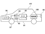
- An electric vehicle includes the power supply device, a traveling motor to which electric power is supplied from the power supply device, a vehicle body including the power supply device and the motor, and a vehicle body driven by the motor. It is equipped with wheels to run.
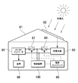
- the power storage device includes the above power supply device and a power supply controller that controls charging / discharging to the power supply device, and the power supply controller enables charging of the battery cell by electric power from the outside. At the same time, the battery cell is controlled to be charged.
- the above battery modules can achieve high safety by protecting the electronic circuit block equipped with the voltage detection circuit from high temperature and high pressure exhaust gas while lowering the height, and can efficiently dissipate the electronic circuit block.
- FIG. 3 is a cross-sectional view taken along the line III-III of the battery module shown in FIG.
- FIG. 3 is a cross-sectional view taken along the line III-III of the battery module shown in FIG.
- FIG. 3 is a cross-sectional view taken along the line III-III of the battery module shown in FIG.
- FIG. 7 is a circuit diagram which shows an example of an electronic circuit block.
- FIG. 7 is a sectional view taken along line VIII-VIII of the battery module shown in FIG. 7.
- FIG. 1 It is a schematic plan view of the power supply device including a plurality of battery modules. It is a schematic circuit diagram of the power supply device shown in FIG. It is a block diagram which shows an example which mounts a battery module in a hybrid vehicle which runs by an engine and a motor. It is a block diagram which shows an example which mounts a battery module in an electric vehicle which runs only by a motor. It is a block diagram which shows the example which uses the battery module for a power storage device. It is an exploded perspective view of the conventional battery module.
- a gas duct is arranged on the upper surface of the battery laminate in order to exhaust the exhaust gas ejected from the exhaust valve of the battery cell to the outside.
- the gas duct is provided to exhaust the high-temperature and high-pressure exhaust gas discharged from the exhaust valve of the battery cell to the outside.
- the exhaust valve of the battery cell opens when the internal pressure rises to the set value to prevent the battery case from exploding. This exhaust valve opens when it detects that the internal pressure of the battery becomes abnormally high, but the internal pressure of the battery cell causes overcharging, overdischarging, and an internal short circuit, resulting in a combustion event inside the battery cell.
- the high-temperature and high-pressure exhaust gas ejected from the battery cell has an adverse effect such as burning peripheral members, and is therefore exhausted to the outside through a gas duct.
- the gas duct is arranged on the battery laminate in order to guide the exhaust gas from the exhaust valve of the battery cell to the outside.
- the gas duct is provided with an inflow hole for allowing the exhaust gas ejected from the exhaust valve of each battery cell to flow into the inside.
- the power supply module includes a circuit board on which a voltage detection circuit for detecting the voltage of the battery cells is mounted in order to prevent overcharging or overdischarging of each battery cell.
- the voltage detection circuit provided on the circuit board is connected to the electrode terminals of the battery cells via the voltage detection line and detects the voltage of each battery cell.
- the circuit board is arranged on the upper surface of the battery laminate, and the voltage detection line can be shortened.
- the short voltage detection line has a small line impedance and can accurately detect the cell voltage.
- the gas duct is arranged on the electrode surface of the battery laminate and connected to the exhaust valve of the battery cell
- the circuit board is arranged on the gas duct to form the circuit board.
- the voltage detection circuit can be connected to the battery cell via the voltage detection line.
- a gas duct extending in the stacking direction of the battery cells is arranged on the upper surface of the battery laminate so that the exhaust gas ejected from the battery cells can be smoothly exhausted to the outside, and further, the battery cells can be smoothly exhausted to the outside.
- a circuit board extending in the stacking direction of the above can be arranged, and the voltage detection circuit of the circuit board can be connected to the electrode terminal of the battery cell with a short voltage detection line.
- the high-temperature and high-pressure exhaust gas ejected from the battery cell has an adverse effect such as burning the circuit board.
- the electronic components of the voltage detection circuit on the circuit board are adversely affected by high-temperature and high-voltage exhaust gas, which reduces safety.
- the connector and lead wire of the voltage detection line are also arranged on the upper surface of the battery laminate, but the high temperature and high pressure exhaust gas burns the connector and lead wire, and the heat of combustion of these burns the battery cell. It causes smoke and fire in a chain reaction, which reduces safety.
- the exhaust gas is abnormally high temperature and high pressure, it is difficult for the gas duct to completely discharge the gas to the outside.
- the circuit board is separated from the terminal surface of the battery cell by the gas duct, the exhaust gas leaking from the gas duct may burn the circuit board and further increase the heat damage. Further, the exhaust gas contains foreign substances such as metal pieces inside the battery cell, which may cause a short-circuit failure of the electronic circuit of the circuit board.
- the battery module is required to be miniaturized as a whole in almost all applications without exception. This is to improve the performance by increasing the charge / discharge capacity with respect to the unit volume.
- the components arranged on the upper surface of the battery laminate include a gas duct for discharging exhaust gas, an electrode terminal protruding from the terminal surface, and a metal plate bus bar for connecting adjacent electrode terminals.
- a battery module in which a large number of parts such as a gas duct, a circuit board, and a lead wire are arranged on the upper surface of a battery laminate cannot be miniaturized by lowering the height of the battery module only by improving the component arrangement.
- the substrate has a detrimental effect of substantially increasing the volume, especially the height, of the battery module.
- the circuit board is made thinner and smaller, the drawback that the thermal energy of the heat-generating components mounted on the circuit board cannot be efficiently dissipated becomes remarkable. Since heat-generating components such as semiconductor elements and discharge resistors are mounted on the circuit board, it is extremely important to efficiently dissipate heat energy and make the temperature rise of the heat-generating components lower than the set temperature.
- the power supply module described in the following embodiment can eliminate the above drawbacks due to its unique structure.
- the battery module of the first embodiment of the present invention includes a battery laminate formed by stacking a plurality of battery cells, a pair of end plates arranged at both ends of the battery laminate in the stacking direction, and a pair of ends. It includes a bind bar connecting plates and an electronic circuit block on which a voltage detection circuit for detecting the voltage of a battery cell is mounted.
- the electronic circuit blocks are arranged on the outer surfaces of both end plates arranged at both ends of the battery laminate, and each electronic circuit block is connected to the battery cell via a voltage detection line.
- the above battery module can reduce the size of the battery module and increase the charge / discharge capacity with respect to the unit volume while protecting the circuit board from the high-temperature and high-pressure exhaust gas ejected from the exhaust valve of the battery cell, and further, the voltage detection circuit.
- the advantage is that the thermal energy of the electronic circuit block to be mounted can be efficiently dissipated to the end plate and the outside, and the temperature rise of the electronic circuit block can be reduced.
- the above structure has a feature that since the electronic circuit block can be arranged on the surface of the end plate in a vertical posture, air can convection smoothly on the surface of the electronic circuit block and heat can be efficiently dissipated.
- the electronic circuit block which is the end plate and is shielded from high-temperature and high-pressure exhaust gas, ensures high safety as a normal operating state even in an abnormal use state of the battery cell in which the exhaust valve is opened.
- the characteristic of being able to efficiently dissipate the heat energy of the electronic circuit block also realizes the feature that the temperature rise can be reduced while the electronic circuit block is miniaturized.
- the temperature rise of the electronic components mounted on the electronic circuit block is also reduced, and the stable operation of the electronic components can be guaranteed.
- the electronic circuit blocks are arranged on both end plates arranged at both ends of the battery laminate, that is, the electronic circuit blocks are divided into two sets and arranged on the end plates.
- the voltage detection line connecting the cell and the electronic circuit block can be shortened. This is because each battery cell can be connected to a nearby electronic circuit block via a voltage detection line. Being able to shorten the voltage detection line is extremely important for detecting the voltage of the battery cell with higher accuracy. This is because a long voltage detection line has a high impedance and is easily affected by noise, and the voltage drop is also large, and the noise and the voltage drop cause a detection error of the cell voltage. Since the detection accuracy of the cell voltage affects the deterioration and life of the battery module, it is extremely important how highly accurate it can be detected.
- the electronic circuit block is arranged on the outer surface of the end plate without arranging the electronic circuit block on the electrode surface of the battery laminate, the high temperature and high pressure ejected from the battery cell while designing the whole low.
- the electronic circuit block can be protected from exhaust gas.
- the end plate is arranged between the battery laminate and the electronic circuit block, this end plate can block the electronic circuit block from the exhaust gas of the battery cell and protect the electronic circuit block from the exhaust gas of high temperature and high pressure. Therefore, even in an abnormal state, the normal operation of the electronic circuit block is guaranteed and high safety is guaranteed.
- the voltage detection line connecting the battery cell and the electronic circuit block is shortened to lower the impedance of the line, and particularly to reduce the electrical resistance. It also realizes the feature that the voltage of each battery cell can be detected with high accuracy by making it smaller. Further, since the heat generated by the electronic circuit block can be efficiently dissipated to the end plate, the temperature rise of the electronic circuit block can be reduced. Furthermore, since the electronic circuit block can be arranged on the surface of the end plate in a vertical position, air can be smoothly convected on the surface of the electronic circuit block to improve the cooling efficiency.
- the structure that can efficiently dissipate heat from the electronic circuit block makes the temperature rise locally small even if the electronic circuit block is miniaturized and the heat generation is concentrated in a narrow area, and the temperature of the electronic component that generates heat in the electronic circuit block. The rise is also small, and more stable operation can be guaranteed.
- a battery laminate composed of a plurality of battery cells is divided into a plurality of battery units in the middle of the stacking direction of the battery cells, and each battery unit has a voltage detection line. It is connected to separate electronic circuit blocks via.
- the battery module according to the third embodiment of the present invention includes a gas duct in which the battery laminate is connected to an opening of an exhaust valve provided in the battery cell, and the gas duct is provided at the center of the electrode surface of the battery laminate.
- the battery cells are arranged so as to extend in the stacking direction, and the voltage detection line is arranged along the side edge of the gas duct.
- the above battery module can reduce the wiring space of the voltage detection line, it has the advantage that the width of the gas duct arranged on the electrode surface can be widened to smoothly exhaust the exhaust gas and prevent gas leakage.
- the reason why gas leakage can be prevented and safety can be ensured is that the increase in internal pressure of the gas duct is reduced.
- the wiring space of the voltage detection line can be reduced because the voltage detection line can be branched into two sets of electronic circuit blocks and wired to reduce the number of voltage detection lines connected to each electronic circuit block. ..
- voltage detection lines are arranged on both sides of the gas duct.
- the above battery modules have the advantage that the wiring space on both sides of the gas duct can be further reduced because the voltage detection lines connected to each electronic circuit block can be separated and wired on both sides of the gas duct.
- the electronic circuit block includes a cell balance adjusting circuit for adjusting the cell balance of each battery cell, and the cell balance adjusting circuit energizes the voltage detection line for each. Adjust the cell balance of the battery cell.
- each battery cell can be quickly cell-balanced by using the voltage detection line together for cell balance adjustment. This is because the cell-balancing voltage detection line can be shortened and the electrical resistance can be reduced by connecting it to a nearby electronic circuit block. By shortening the voltage detection line and reducing the electrical resistance, the voltage drop in the wiring during cell balance is reduced, and the voltage detection accuracy is improved.
- the voltage detection line is a wire harness or a printed circuit board.
- the printed circuit board of the voltage detection line is a flexible printed circuit board (FPC).
- the above battery module can be connected to an electronic circuit block in which the voltage detection line is divided into two and arranged nearby, the voltage detection line can be shortened, and the flexible printed circuit board can be shortened for mass production at low cost.
- the battery module of the eighth embodiment of the present invention includes a communication terminal capable of transmitting a signal by cascading a plurality of electronic circuit blocks in an electronic circuit block, and cuts off a direct current to transmit an AC signal to the communication terminal. It is internally connected via a coupling element that is passed through.
- the communication terminals of the above battery modules are internally connected via a coupling element, they have the advantage of being able to connect to other communication terminals and transmit signals without adjusting to the DC level. This is particularly effective in a device in which a plurality of battery modules are connected in series.
- a potential difference is generated in the ground line of each battery module. Since the communication terminal of the electronic circuit block transmits a signal with the ground line as the reference potential, the communication terminal having a potential difference in the ground line applies a bias voltage to shift the DC level of the ground line and is connected to the communication terminal.
- the potential difference of the ground line needs to be set to zero level, but this circuit configuration becomes considerably complicated.
- the ground line changes stepwise, so that equalizing the ground lines with a plurality of bias voltages becomes an extremely complicated circuit configuration. Furthermore, since the bias voltage that equalizes the ground lines shifts with temperature, it is necessary to control the temperature characteristics extremely accurately, and the circuit configuration becomes more complicated. In the above battery modules, it is not necessary to equalize the DC level of the ground line with the bias voltage, and a large number of battery modules are connected in series and the communication terminals of the battery modules having a potential difference are easily connected to the ground line for signals. Has the feature of being able to transmit.
- the coupling element is any one of a coupling capacitor, a transformer, and a photoelectric transmission element.
- the power supply device is a power supply device including a plurality of the above battery modules, in which adjacent battery modules are connected to a power line by an external communication line, and the power line is connected to an output terminal of the battery module. Connected, the external communication line is connected to the communication terminal, the external communication line is connected to the communication terminal located at the end of the battery module which is connected to the power line, and both the power line and the external communication line are connected. , Connected to the same end of the battery module.
- an external communication line is connected to a pair of communication terminals in which battery modules arranged adjacent to each other are arranged closest to each other.
- the battery modules shown in the following examples are mainly suitable for powering electric vehicles such as hybrid cars and plug-in hybrid cars that run on both engines and motors, electric vehicles that run only on motors, and electric bikes that run on motors. Is.
- the battery module of the present invention is also suitable as a power source for a power storage device other than an electric vehicle, which requires a large output.
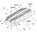
- the battery modules 10 shown in FIGS. 1 to 4 are arranged at both ends of the battery laminate 2 in which a plurality of battery cells 1 are laminated in the thickness direction and the battery cells 1 of the battery laminate 2 in the stacking direction.
- the battery module 10 shown in the figure is arranged above the gas duct 5 connected to the opening of the exhaust valve 1a provided in each battery cell 1 and above the battery laminate 2 and above the gas duct 5.
- the cover case 8 is provided with a cover case 8 and a base plate 9 arranged below the battery laminate and fixing the end plate 3.
- the battery cell 1 is a rectangular secondary battery having a width wider than the thickness, in other words, a square secondary battery thinner than the width, and is laminated in the thickness direction to form a battery laminate 2.
- the battery cell 1 is a lithium ion secondary battery.
- the battery cell can be any other rechargeable secondary battery, such as a nickel metal hydride battery or a nickel cadmium battery.
- positive and negative electrode plates are housed together with an electrolytic solution in an outer can having a closed structure.
- the outer can is made by press-molding a metal plate such as aluminum or an aluminum alloy into a square shape, and the opening is hermetically sealed with a sealing plate.
- the sealing plate is made of the same aluminum or aluminum alloy as the outer can, and the positive and negative electrode terminals 11 are fixed, and an exhaust valve is provided between the electrode terminals 11.
- the positive and negative electrode terminals 11 are in a state in which at least one of the electrode terminals 11 is insulated from the sealing plate.
- the battery cell 1 is provided with positive and negative electrode terminals 11 with the sealing plate as the terminal surface 1X. Further, in the battery cell 1, the bottom surface and the side surface of the outer can are covered with an insulating film.
- the plurality of battery cells 1 are laminated so that the thickness direction of each battery cell 1 is the stacking direction to form the battery laminate 2.
- the plurality of battery cells 1 are laminated so that the terminal surfaces 1X provided with the positive and negative electrode terminals 11 are arranged on the same plane to form the electrode surfaces 2X to form the battery laminate 2.
- the battery laminate 2 has an insulating spacer 12 sandwiched between the stacked battery cells 1.
- the insulating spacer 12 in the figure is made of an insulating material such as resin in the form of a thin plate or sheet.
- the insulating spacer 12 shown in the figure has a plate shape having a size substantially equal to the facing surface of the battery cells 1, and the insulating spacers 12 are laminated between the battery cells 1 adjacent to each other to connect the adjacent battery cells 1 to each other. Insulated.
- a spacer having a shape in which a flow path of a cooling gas is formed between the battery cell and the spacer can also be used.
- a metal bus bar 14 is connected to the positive and negative electrode terminals 11 of the adjacent battery cells 1, and a plurality of battery cells 1 are connected in series or in parallel, or in series and in parallel by the bus bar 14. ing.
- the output voltage and the capacity that can be charged and discharged are set values depending on the number of battery cells 1 to be stacked.
- the output voltage can be increased by the number of battery cells 1 connected in series, and the charge / discharge capacity can be increased by the number of battery cells 1. Since the battery module 10 sets the output voltage and the capacity as set values in a connected state in which the number of battery cells 1 constituting the battery laminate 2 and the battery cells 1 are connected in series with each other, the number of battery cells 1 and the connected state are used. It is considered to be the optimum state in consideration of.
- the bus bar 14 is provided with a connection portion (not shown) for connecting to the electrode terminal 11.
- the bus bar 14 is connected by irradiating a boundary connecting the connection portion and the electrode terminal 11 with a laser beam and welding the connection portion to the electrode terminal 11.
- the bus bar is provided with a male screw on the electrode terminal to open a through hole for inserting the electrode terminal, and a nut is screwed into the male screw of the electrode terminal inserted through the through hole to connect to the electrode terminal.
- the electrode terminal may be provided with a female screw hole, and a set screw penetrating the bus bar may be screwed into the female screw hole to connect to the electrode terminal.
- the battery module 10 may be provided with a resin insulating cover (not shown) on the upper surface of the battery laminate 2.
- the insulating cover is provided with an opening, and the electrode terminal 11 is exposed from the opening, and a metal plate bus bar 14 is connected to the electrode terminal 11 exposed from the opening of the insulating cover on the upper surface side of the insulating cover.
- a plurality of battery cells 1 can be connected in a predetermined arrangement.
- End face spacer 13 In order to insulate the battery laminate 2 from the metal end plate 3, the end plates 3 can be arranged on both end faces with the end face spacers 13 interposed therebetween.
- the end face spacer 13 is arranged between the battery laminate 2 and the end plate 3 to insulate the end plate 3 from the battery laminate 2.
- the end face spacer 13 is made of an insulating material such as resin in the form of a thin plate or sheet.
- the end face spacer 13 is provided with a plate portion having a size capable of covering the entire facing surface of the battery cell 1, and this plate portion is laminated between the battery cell 1 and the end plate 3 arranged at both ends of the battery laminate 2. is doing.
- End plate 3 The end plates 3 are on both end faces of the battery stack 2 in the stacking direction of the battery cells 1 and fix the battery stack 2.
- the end plate 3 is a metal plate, and is a quadrangular plate whose outer shape is substantially equal to the outer shape of the battery cell 1 or slightly larger than that of the battery cell 1.
- the end plate 3 can be manufactured of a high-strength rope to have a tough structure.
- the end plate 3 may be a single metal plate, a structure in which a plurality of metal plates are laminated, or a laminate of a metal plate and plastic.
- the end plate 3 made of one metal plate has a large heat capacity and can efficiently absorb the heat energy of the electronic circuit block 6.
- the surface side on which the electronic circuit block 6 is fixed is at least a metal plate material. This is because the electronic circuit block 6 is fixed in a heat-coupled state to improve heat dissipation characteristics.
- the end plate 3 can have a laminated structure of an aluminum plate and a high-strength rope plate. This end plate has a structure in which an electronic circuit block is fixed with the surface side as an aluminum plate, and the aluminum plate and the high-strength rope plate are laminated in a surface contact state so that heat can be efficiently conducted from the aluminum plate to the high-tensile rope plate. You can also do it.
- the end plate is not necessarily made of metal, but may be made of plastic having excellent strength such as engineering plastic.
- the bind bar 4 extends in the stacking direction of the battery cells 1 and fixes both ends thereof to the end plates 3, and the battery stack 2 is fixed by the pair of end plates 3.
- the bind bar 4 shown in FIGS. 1 and 2 is a metal plate having a predetermined vertical width and a predetermined thickness along the side surface of the battery laminate 2, and is arranged so as to face both side surfaces of the battery laminate 2. ..
- the bind bar 4 presses both end surfaces of the battery laminate 2 with a strong pressure to charge and discharge the battery cell 1 to expand, and arranges the battery cells 1 at a fixed position.
- As the metal plate of the bind bar 4 a high-strength rope is preferably used.
- the bind bar 4 of the metal plate is press-molded to form a predetermined shape.
- the bind bar 4 has both ends of the battery laminate 2 on the outer surface of the end plate 3 at both ends in the stacking direction in order to fix both ends to the pair of end plates 3.
- the fixing portion 4A is provided by bending along the above.
- the bind bar 4 fastens the pair of end plates 3 by screwing the fixing portion 4A into the end plate 3.
- the bind bar 4 is formed by bending the lower end portion into an L shape to form the lower connecting piece 4B.
- the lower connecting piece 4B is laminated on the lower surface side of both side portions of the base plate 9 and connected to the base plate 9.
- the bind bar 4 is formed by bending the upper end portion to form a pressing piece 4C that presses the upper end portion of the upper surface of the battery laminate 2.
- the pressing piece 4C is separated for each battery cell 1 so that the upper surface of the battery cell 1 of the battery stack 2 can be individually pressed. As a result, each pressing piece 4C can press the battery cell 1 toward the base plate 9 independently of the adjacent pressing piece 4C.
- each battery cell 1 is prevented from rising from the base plate 9 and held in the height direction, and even if vibration, impact, or the like is applied to the battery laminate 2, each battery cell 1 is positioned in the vertical direction. It can be maintained so that it does not shift.
- the bind bar 4 covers and holds the corners of the upper and lower surfaces of the battery laminate 2 on both the left and right sides of the battery laminate 2.
- both ends of the bind bar may be formed into a flat plate shape without being bent into an L shape, and may be configured to be screwed with the side surface of the end plate.
- an engaging structure in which the portion of the bind bar facing the side surface of the end plate is engaged in a stepped shape as a structure in which the bind bar is further screwed in a state of being locked to the side surface of the end plate with a locking structure. May be good.
- an insulating sheet may be interposed between the bind bar 4 and the battery laminate 2.
- the insulating sheet is made of a material having an insulating property, for example, resin, and insulates between the metal bind bar 4 and the battery cell 1.
- the base plate 9 is arranged on the bottom surface of the battery laminate 2 and the end plate 3.
- the end plate 3 is fixed to the base plate 9, and more preferably, the lower end portion of the bind bar 4 is also fixed to the base plate 9.
- the end plate 3 and the bind bar 4 are fixed to the base plate 9 via the fixing screws 15 and 16.
- the fixing screw 15 for fixing the end plate 3 penetrates the end plate 3 in the vertical direction and fixes the end plate 3 to the base plate 9.
- the fixing screw 16 for fixing the bind bar 4 also penetrates the lower connecting piece 4B which is the lower end portion of the bind bar 4 and is fixed to the base plate 9.
- the battery laminate 2 is arranged in a heat-bonded state with the base plate 9 by bringing each battery cell 1 into contact with the base plate 9.
- the base plate 9 can be forcibly cooled to dissipate the heat energy of the battery cell 1 more efficiently.
- the base plate 9 to be forcibly cooled can be forcibly cooled by circulating a refrigerant or a coolant inside.
- the base plate can be forcibly cooled by providing heat radiation fins on the lower surface.
- a cooling plate can be laminated on the lower surface of the base plate in a surface contact state, and forced cooling can be performed by the cooling plate.
- the cooling plate can be forcibly cooled by circulating a refrigerant or a coolant inside.
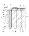
- the gas duct 5 As shown in FIGS. 3 and 4, the gas duct 5 is arranged at a position facing the upper surface of the battery cell 1, that is, the terminal surface 1X of the battery cell 1, and exhausts the exhaust gas ejected from the exhaust valve 1a to the outside. do.
- the gas duct 5 shown in FIG. 4 is arranged at the center of the electrode surface 2X of the battery stack 2 in a posture extending in the stacking direction of the battery cells 1.
- the gas duct 5 has a tubular shape having an internal volume that smoothly discharges the discharged material discharged from the opening of the exhaust valve 1a, opens the lower surface, and is connected to the opening of the exhaust valve 1a of each battery cell 1. There is.
- the gas duct 5 is formed on the upper surface of the battery laminate 2 so that the exhaust gas discharged from the exhaust valve 1a is exhausted to the outside so that there is no gap between the gas duct 5 and the terminal surface 1X of the battery cell 1.
- An opening 5a that is arranged in close contact with the upper surface and opens on the lower surface is connected to the exhaust valve 1a of each battery cell 1.
- the gas duct 5 may be arranged so that exhaust gas does not leak by arranging packing, a sealing material, or the like between the gas duct 5 and the terminal surface 1X.
- the gas duct is a collecting duct arranged on the upper surface of the battery stacking body in a posture extending in the stacking direction of the battery cells, and a branch duct connected to the collecting duct and the tip is connected to the exhaust valve. It can also be configured with.
- the collecting duct can be arranged away from the terminal surface, and the tip of the branch duct can be connected to the opening of the exhaust valve.
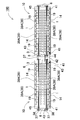
- the battery module 10 of FIGS. 2 and 4 includes two sets of electronic circuit blocks 6.
- the two sets of electronic circuit blocks 6 are fixed to the outer surfaces of both end plates 3 which pressurize and fix the battery laminate 2 from both ends.
- the two sets of electronic circuit blocks 6 include a voltage detection circuit 22 that detects the voltage of the battery cell 1.
- the voltage detection circuit 22 of each electronic circuit block 6 is connected to each battery cell 1 via a voltage detection line 19 to detect the voltage of the battery cell 1.
- the battery module 10 in which the electronic circuit block 6 is divided into two sets and arranged on the end plate 3 can connect the voltage detection line 19 to the battery cell 1 and the nearby electronic circuit block 6, and is therefore shown in FIG. 6 as a reference example.
- the voltage detection line 19 can be shortened as compared with the battery module 70 including one set of electronic circuit blocks 6.
- the battery module 10 of FIG. 4 is divided into two sets of battery units 2A in the middle of the stacking direction of the battery cells 1, and the battery cells 1 of each battery unit 2A are divided into separate electronic circuit blocks via the voltage detection line 19. It is connected to 6.
- the battery module 10 that divides the battery laminate 2 into two at the center can shorten the longest voltage detection line 19 to 1/2 the length of the battery module including the set of electronic circuit blocks 6 shown in FIG. ..
- voltage detection lines 19 are wired on both sides of the gas duct 5 along the side edges of the gas duct 5.
- the battery module 10 can reduce the number of voltage detection lines 19 wired on both sides of the gas duct 5 to narrow the wiring space of the voltage detection lines 19.
- the voltage detection line 19 having a narrow wiring space can widen the width of the gas duct 5 arranged at the center thereof to smoothly exhaust the exhaust gas and prevent gas leakage.
- the plurality of voltage detection lines 19 are wired on the upper surface of the battery laminate 2 as a wire harness or a printed circuit board 39.
- the battery module 10 in which the printed circuit board 39 of the voltage detection line 19 is a flexible printed circuit board 39A (FPC) has a feature that the wiring space of the voltage detection line 19 can be made extremely thin.
- the electronic circuit block 6 shown in FIGS. 2, 4 and 7 includes a connection terminal 37 for connecting a voltage detection line 19 which is a flexible printed circuit board 39A.
- the flexible printed circuit board 39A shown in the figure is provided with a connector 38 for connecting to the electronic circuit block 6 at one end, and by connecting this connector 38 to the connection terminal 37 provided in the electronic circuit block 6, it is easy and reliable. It is possible to connect.
- the electronic circuit block 6 shown in the figure has a thin box shape so that the entire outer shape can be arranged along the outer surface of the end plate, and the connection terminals 37 for connecting the connectors 38 to both ends of the upper surface thereof. Is provided.
- connection terminal 37 can be conveniently wired at a position where it does not interfere with the gas duct 5.
- connection terminal may be arranged at the center of the upper surface of the box-shaped electronic circuit block. In this case, by bending the tip of the voltage detection line (flexible printed circuit board) connected to the connection terminal in a crank shape, the main body of the voltage detection line (flexible printed circuit board) is connected to the connection terminal. Can be wired on both sides of the gas duct.
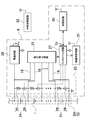
- the electronic circuit block 6 mounts an electronic component that realizes the voltage detection circuit 22 on the circuit board 20 (see FIGS. 5 and 8).
- the electronic circuit block 6 may be a block in which all the electronic circuits including the voltage detection circuit 22 are integrated circuits and the integrated circuits are embedded in a package of an insulating material.
- the electronic circuit block 6 can be a block in which the metal plate of the radiator 21 is arranged on the surface.
- the radiator 21 is thermally coupled to heat-generating components built in the electronic circuit block 6, for example, a semiconductor element such as a FET that controls the discharge resistance and current of the cell balance adjustment circuit, and heat energy of these heat-generating components. Dissipate heat to the outside.
- the electronic circuit block 6 has an electronic component mounted on a circuit board 20 to form a plate shape as a whole, or an integrated circuit embedded in a package to form a plate shape.
- the electronic circuit block 6 including the voltage detection circuit 22 detects the voltage of the battery cell 1 whose voltage fluctuates due to charging / discharging, and sets the battery voltage as a set range to prevent overcharging or overdischarging of each battery cell 1. ..
- the battery module 10 may include a control circuit 30 for controlling the charge / discharge current of the battery stack 2 in the electronic circuit block 6.
- the control circuit 30 controls the charging / discharging current to prevent overcharging and overdischarging of the battery cell 1.
- the voltage detection circuit 22 transmits the voltage data of the battery cell 1 to the control circuit 30.
- the electronic circuit block can also transmit battery information to an external control circuit without providing a control circuit, and control the charging / discharging current of the battery module 10 with the external control circuit.
- the voltage detection circuit 22 preferably detects the voltage of all the battery cells 1. However, the voltage detection circuit 22 does not necessarily detect the voltage of all the battery cells 1.
- the battery cell 1 constituting the battery laminate 2 is divided into a plurality of battery units, and the voltage of each battery unit is divided. Can also be detected.
- a battery unit in which a plurality of battery cells 1 are connected in parallel can detect the voltage of the battery unit and detect the voltage of all the battery cells.
- the battery unit in which a plurality of battery cells are connected in series detects the voltage of the battery unit and detects the total voltage of the battery cells connected in series.
- a battery unit in which a plurality of battery cells are connected in series is composed of 2 to 5 battery cells.
- this battery unit detects the voltage of the battery unit and detects the total voltage of 2 to 5 battery cells 1, the voltage of the battery cells is 1/2 to 1/5 of the detected total voltage.
- the voltage of the battery cell 1 changes with the remaining capacity.
- the voltage of the battery cell 1 becomes higher than the preset maximum voltage when it is overcharged, and becomes lower than the minimum voltage when it is overdischarged.
- the voltage detection circuit 22 detects the voltage of the battery cell 1 and transmits it to the control circuit 30, and the control circuit 30 controls the charging / discharging current so that the voltage of the battery cell 1 is within the set range.
- the battery module 10 As the battery module 10 is repeatedly charged and discharged, the remaining capacity and voltage of each battery cell 1 become unbalanced.
- the battery cells 1 connected in series are charged and discharged with the same current. Although they are charged and discharged with the same current, the electrical characteristics of each battery cell 1 are not completely the same. Therefore, in the battery module 10 in which a plurality of battery cells 1 are connected in series, the voltage and the remaining capacity of each battery cell 1 become unbalanced as charging and discharging are repeated.
- An imbalance in the battery cell 1 causes the specific battery cell 1 to be overcharged or overdischarged. Since the battery module 10 charges and discharges all the battery cells 1 at the same time, the imbalance of the battery cells 1 causes the specific battery cells 1 to be overcharged or overdischarged. Overcharging and overdischarging of the battery cell 1 deteriorates the electrical characteristics of the battery cell 1 and causes deterioration, and also reduces the safety of the battery module 10.
- the cell balance adjustment circuit 23 eliminates the imbalance of the voltage of
- the electronic circuit block 6 also mounts a cell balance adjusting circuit 23 that equalizes the voltage of the battery cell 1.
- the cell balance adjustment circuit 23 uses the voltage detection line 19 to discharge the high voltage battery cell 1 and charge the low voltage battery cell 1 to equalize the voltage of the battery cell 1 and unbalance it. Eliminate.
- An example of the circuit diagram of the cell balance adjustment circuit 23 is shown in FIG. Since the voltage of the battery cell 1 having a large remaining capacity is high, the battery cell 1 having a high voltage can be discharged to equalize the remaining capacity.
- the cell balance adjustment circuit 23 shown in this figure discharges the battery cell 1 having a high voltage with the discharge resistor 25 to eliminate the imbalance. However, the cell balance adjustment circuit 23 is not specified as a circuit that discharges the battery cell 1 with the discharge resistance 25.
- a battery cell having a high voltage is discharged to a power storage device such as a capacitor or a storage battery to store the battery in the power storage device, and the charge of the storage device is discharged to a battery cell having a low voltage to discharge the voltage of the battery cell.
- a power storage device such as a capacitor or a storage battery to store the battery in the power storage device
- the charge of the storage device is discharged to a battery cell having a low voltage to discharge the voltage of the battery cell.
- the cell balance adjustment circuit can also convert the voltage of a high voltage battery cell with a DC / DC converter and charge the low voltage battery cell while controlling the current to equalize the voltage.
- the cell balance adjustment circuit 23 of FIG. 5 includes a discharge circuit 24 in which a switching element 26 is connected in series to the discharge resistor 25, detects each cell voltage, and controls the switching element 26 to be ON / OFF.
- the circuit 27 and the voltage detection circuit 22 that detects the cell voltage of each battery cell 1 are connected.
- the discharge resistor 25 and the discharge circuit 24 of the switching element 26 are connected in parallel with each battery cell 1.
- the cell balance adjusting circuit 23 switches the switching element 26 to ON by the control circuit 27, discharges the battery cell 1 with the discharge resistor 25, and causes the voltage of the battery cell 1 to be discharged. To reduce and equalize.
- the cell balance adjustment circuit 23 is driven by receiving electric power from the battery laminate 2.
- the cell balance adjustment circuit 23 in the figure is operated by the output voltage (Vcc) of the power supply circuit 28 that receives power from the battery stack 2.
- the voltage of the battery laminate 2 can be stepped down by, for example, a DC / DC converter which is a power supply circuit 28, and supplied to the cell balance adjustment circuit 23. According to this circuit configuration, even if the voltage of the battery laminate 2 is high, it can be supplied to the cell balance adjusting circuit 23 as an optimum voltage.
- the control circuit 27 compares the cell voltages of the respective battery cells 1 and controls the switching element 26 so as to equalize the cell voltages of all the battery cells 1.
- the control circuit 27 switches the switching element 26 of the discharge circuit 24 connected to the battery cell 1, which is too high, to ON to discharge the battery.
- the voltage of the battery cell 1 decreases as it is discharged.
- the switching element 26 is switched from ON to OFF when the voltage of the battery cell 1 drops until it is balanced with the other battery cells 1.
- the control circuit 27 discharges the battery cell 1 having a high cell voltage to balance the cell voltages of all the battery cells 1.
- the cell balance adjustment circuit 23 described above equalizes the voltages of all the battery cells 1, but the battery module divides all the battery cells into a plurality of battery units and sets the voltage of the battery cells constituting the battery units as cell cells. After equalizing with the balance adjustment circuit, the voltage of the entire battery unit can be equalized with the unit cell balance adjustment circuit.
- the unit cell balance adjustment circuit detects the unit voltage of each battery unit, discharges the battery unit having a high unit voltage, and equalizes the voltage of each battery unit.
- the electronic circuit block 6 is fixed to the end plate 3 and dissipates heat to the end plate 3.
- the electronic circuit block 6 includes a semiconductor element such as an FET that controls a current and a heat generating element such as a discharge resistor.
- the electronic circuit block 6 can dissipate the heat energy of the heat generating element to the end plate 3 to reduce the temperature rise.
- the temperature rise of the electronic circuit block 6 adversely affects the built-in heat generating element and the like.
- the cell balance adjustment circuit 23 discharges the battery cell 1 with the discharge resistor 25 to lower the voltage, but the discharge resistor 25 generates heat due to the Joule heat of the discharge current.
- the discharge resistor 25 can increase the current and quickly reduce the voltage of the battery cell 1 in a short time, but the Joule heat that heats the discharge resistor 25 increases in proportion to the square of the discharge current, so that the voltage can be rapidly reduced.
- the cell balance adjustment circuit 23, which can reduce the voltage of the battery cell 1 to shorten the equalization time, generates a large amount of heat energy. Since the cell balance adjusting circuit 23 equalizes the battery cells 1 at the timing when the battery cells 1 are not charged or discharged, the equalization time is required to be shorter. Since the reduction of the equalization time can be realized by increasing the current of the discharge resistor 25, how efficiently the heat generation energy of the discharge resistor 25 can be dissipated is an important factor for specifying the equalization time.
- the temperature rise due to the heat generation energy of the heat-generating parts leads to the failure of the parts, it is designed to increase the overall temperature so that the heat-generating parts do not rise abnormally, or to reduce the amount of heat generated per unit time such as discharge resistance. Will be done.
- the electronic circuit block 6 is miniaturized so that it can be arranged in a narrow space, the heat radiation area is reduced, the heat radiation energy is reduced, and the temperature rise is large.
- an electronic circuit block that has been miniaturized so that it can be arranged in a small space between a gas duct and a bus bar, such as a conventional battery module has a small heat dissipation area, so that it is necessary to reduce heat dissipation energy.
- the electronic circuit block arranged in a narrow space needs to reduce the heat radiation energy, and the time for equalizing the battery cells becomes long.
- Battery modules in which a large number of battery cells are stacked are used for large-capacity applications such as battery modules for driving vehicle motors and power storage devices, so the capacity of battery cells is also considerable. big.
- the capacity imbalance due to the battery cell voltage imbalance increases relatively as the battery cell capacity increases. Therefore, this type of battery module is capable of increasing the discharge current because the equalization time of the battery cells is shortened as much as possible and equalized quickly, but the increase in the discharge resistance increases the heat generation energy. Therefore, it is required to increase the heat dissipation area.
- the electronic circuit block is required to be miniaturized in order to be arranged in a narrow space, and it is necessary to increase the heat dissipation area and increase the size in order to discharge with a large current and shorten the equalization time. For this reason, in an electronic circuit block, miniaturization and shortening of equalization time are mutually contradictory characteristics, and both characteristics cannot be satisfied, and miniaturization required for arranging in a limited space is achieved. However, there is a need for issues that contradict the increase in size in order to have high discharge capacity.
- the end plate 3 has an extremely large heat capacity, a small temperature rise with respect to the heat energy to be absorbed, and the equalization time of the battery cell 1 can be shortened.
- the end plate 3 has a large surface area and a large amount of heat radiation energy from the surface, which also makes the temperature rise small. Further, in the structure in which the end plate 3 is fixed to the base plate 9, heat energy is conducted from the end plate 3 to the base plate 9, and the temperature rise is further reduced.
- the end plate 3 is forcibly cooled by the base plate 9, the temperature rise is further reduced, and the cooling effect of the electronic circuit block 6 is further increased. Therefore, the temperature rise of the electronic circuit block 6 is reduced to an ideal state.
- the electronic circuit block 6 is fixed to the outer surface of the end plate 3.
- the battery module 10 has a feature that heat generation energy of an electronic circuit block 6 can be conducted to a fixed end plate 3 to dissipate heat, and heat can be dissipated from an exposed surface to the outside air more efficiently.
- the outer shape of the electronic circuit block 6 fixed to the surface of the end plate 3 is smaller than the outer shape of the end plate 3, and does not protrude from the outer peripheral edge of the end plate 3.
- the electronic circuit block 6 does not increase the outer shape of the battery module 10, and the electronic circuit block 6 can efficiently dissipate heat while being miniaturized.
- the thickness of the electronic circuit block 6 is set so as not to protrude from the tip edge of the base plate 9 to the outer surface in a plan view.
- the outer shape in a plan view is not larger than that of the base plate 9, and the electronic circuit block 6 can be arranged at an ideal position while reducing the overall size.
- the end plate 3 is pressed from the inside with a strong pressure by the battery cell 1 which shows physical properties that expand when charged and discharged.
- the end plate 3 which is pressed by the battery laminate 2 and whose both side edges are fixed by the bind bar 4 is curved by the pressure of the battery laminate 2. If the electronic circuit block 6 is deformed by the curved end plate 3, the components of the electronic circuit block 6 are adversely affected. For example, in the electronic circuit block 6 in which electronic components are fixed to the circuit board, adverse effects such as bending of the circuit board and damage to the conductive portion occur.
- a part of the upper edge portion preferably the central portion, is locally fixed to the end plate 3, and the lower portion is fixed to the tip end portion of the base plate 9.
- the deformation does not adversely affect the electronic circuit block 6.
- the battery module 10 since a part of the upper edge portion of the electronic circuit block 6 is locally fixed to the end plate 3, the battery module 10 does not deform together even if the end plate 3 is curved. Further, since the lower portion of the electronic circuit block 6 is fixed to the tip end portion of the base plate 9, the upper portion and the lower portion are securely fixed to each other. That is, the electronic circuit block 6 is firmly fixed to the end plate 3 and the base plate 9 without being adversely affected by the deformation of the end plate 3.
- the battery module 10 for fixing the electronic circuit block 6 to the base plate 9 arranges the electronic circuit block 6 at a position different from the fixing hole 17 in a plan view, so that the electronic circuit block 6 is fixed to the end plate 3 and the base plate is fixed.
- 9 can be easily and securely fixed to the equipment used such as the chassis of the vehicle.
- the battery module 10 of FIG. 7 is provided with fixing holes 17 on both sides of the base plate 9, and the intervals between the fixing holes 17 are set to a width in which the electronic circuit block 6 can be arranged.
- the electronic circuit block 6 is preferably insulated and fixed to the end plate 3.
- the electronic circuit block 6 is fixed by arranging an insulating sheet 18 between the electronic circuit block 6 and the end plate 3.
- the insulating sheet 18 is an elastic sheet made of a rubber-like elastic body, and can always hold the curved end plate 3 and the electronic circuit block 6 in a heat-bonded state.
- the electronic circuit block 6 insulated and fixed to the end plate 3 is a battery laminate arranged inside the end plate 3 while having a structure in which a metal radiator 21 or the like is exposed on the surface to efficiently dissipate heat. Insulation characteristics can be improved with respect to 2, and reliability can be improved.
- the battery module 10 in which the end plates 3 are arranged on both end surfaces of the battery laminate 2 can prevent electric shock and electric leakage by insulating the end plates 3 from the ground line.
- the end plate 3 insulated from the ground line has a high-voltage battery laminate 2 arranged inside.
- the end plate 3 insulated from the battery laminate 2 has a high leakage resistance with the battery laminate 2, but the leakage resistance may decrease due to various factors. For example, dew condensation water between the end plate 3 and the battery laminate 2 causes a decrease in leakage resistance.
- the electronic circuit block 6 insulated from the end plate 3 is insulated from the end plate 3 even if the contact resistance between the end plate 3 and the battery laminate 2 decreases, thereby preventing adverse effects such as electric leakage and electric shock. To ensure high safety and reliability. However, since the end plate is insulated from the battery laminate, the end plate can also be connected to the ground line.
- the cell balance adjusting circuit 23 Since the above battery module 10 can efficiently dissipate heat generated by the cell balance adjusting circuit 23 of the electronic circuit block 6 by the end plate 3, the cell balance adjusting circuit 23 has a feature that the battery cells 1 can be quickly equalized. This is because the power consumption of the cell balance adjusting circuit 23 can be increased, the battery cell 1 can be discharged with a large current, and the voltage of the high voltage battery cell 1 can be quickly reduced.
- the cell balance adjustment circuit 23 discharges the high-voltage battery cell 1 to eliminate the voltage imbalance, or charges the low-voltage battery cell 1 with the high-voltage battery cell 1 to equalize the voltage.
- the circuit that discharges and equalizes the high-voltage battery cell 1 is a cell balance adjustment circuit 23 that discharges the high-voltage battery cell 1 with the discharge resistance 25 and charges the low-voltage battery cell 1 with the high-voltage battery cell 1. Supply power from the high-voltage battery cell 1 to the low-voltage battery cell 1 to equalize.
- the discharge resistance 25 that discharges the battery cell 1 and the semiconductor element that is the switching element 26 that controls the discharge current of the discharge resistance 25 generate heat.
- This circuit has a structure that efficiently discharges the heat energy of the discharge resistor 25 and the semiconductor element, and can shorten the time for equalizing the discharge current of the discharge resistor 25 and the semiconductor element by increasing the discharge current.
- the discharge can be efficiently discharged and the discharge current can be increased. Further, in the cell balance adjustment circuit that charges the low voltage battery cell with the high voltage battery cell, the semiconductor element that controls the charging current from the high voltage battery cell to the low voltage battery cell generates heat. The current of the element can be increased to shorten the equalization time.
- the electronic circuit block 6 fixed to the end plate 3 is provided with a wireless communication circuit 31, and information such as a battery voltage detected by the voltage detection circuit 22 by the wireless communication circuit 31 is provided. Can be wirelessly transmitted to the central control circuit 33.
- the electronic circuit block 6 does not need to be connected to the central control circuit 33 by a line for external connection, and has a feature that wiring can be easily performed.
- the electronic circuit block 6 can wirelessly transmit information to the central control circuit 33 that controls the traveling motor of the vehicle.
- the battery module having this structure simplifies the complicated wire harness peculiar to the vehicle, prevents the wire harness from having unavoidable adverse effects such as poor contact, and can realize high reliability for a long period of time.
- the electronic circuit block 6 provided with the wireless communication circuit 31 is required to have a characteristic of eliminating a transmission error due to external noise.
- the metal end plate 3 can shield the surface of the electronic circuit block 6 to reduce the influence of external noise.
- the wireless communication circuit 31 can wirelessly transmit information stably and accurately in the end plate 3 provided with the shield convex portion 32 that shields the outer peripheral edge of the electronic circuit block 6 in an integrated structure. Furthermore, by connecting the end plate to the ground line, the shielding effect can be improved and the influence of external noise can be reduced.
- the electronic circuit block 6 includes a communication circuit (not shown) for cascading a plurality of electronic circuit blocks 6 to transmit a signal.
- the communication circuit is connected to the communication terminal 43 via the coupling element 46.
- the communication circuit transmits to the coupling element 46 signals that are alternately transmitted between the detection circuit blocks 6 connected to each other.
- the communication terminal 43 is used as a terminal for connecting the electronic circuit blocks 6 arranged on both sides of the battery module 10, or as a terminal for connecting the electronic circuit blocks 6 of the plurality of battery modules 10. NS.
- the electronic circuit blocks 6 arranged on both sides of one battery module 10 are connected to each other via an internal communication line 45. Further, the electronic circuit blocks 6 of the different battery modules 10 are connected to each other via the external communication line 44.
- the electronic circuit block 6 shown in the figure includes a plurality of communication terminals 43, and these communication terminals 43 have a common terminal structure that can be connected to both the internal communication line 45 and the external communication line 44.
- the electronic circuit block 6 can be provided with a pair of communication terminals 43 on the left and right sides.
- One of the pair of communication terminals 43 is connected to an electronic circuit block having a higher potential, and the other is connected to an electronic circuit block having a lower potential.
- each communication terminal 43 since it is not necessary to consider the potential, each communication terminal 43 has a configuration capable of communicating regardless of whether it is connected to the upper electronic circuit block or the lower electronic circuit block. Therefore, the electronic circuit block 6 having this structure can be connected to the internal communication line 45 or the external communication line 44 while selecting either the left or right communication terminal 43 while being arranged on both sides of the battery module. It has the feature that line wiring can be done efficiently.
- the electronic circuit block 6 shown in the figure is provided with a pair of communication terminals 43 on the left and right sides of the upper surface.
- the pair of communication terminals 43 formed on the upper surface of the electronic circuit block 6 may be provided inside the connection terminals 37 formed at both ends, or, although not shown, outside the connection terminals. It can also be provided.
- the electronic circuit block may be provided with a pair of communication terminals on the left and right side surfaces in place of the upper surface or in addition to the upper surface.
- a large-capacity power supply device 100 can be realized by connecting a plurality of battery modules 10 in series or in parallel with a power line 42.
- the large-capacity power supply device 100 can be effectively used as a power source for an electric vehicle such as a hybrid car or an electric vehicle, and further as a power storage device.
- the power supply device 100 connects the adjacent battery module 10 to the power line 42 by an external communication line 44.
- the power line 42 is connected to the output terminal 41 of the battery module 10 and connects the battery modules 10 in series or in parallel.
- the external communication line 44 is a communication terminal 43 provided in the electronic circuit block 6 and is connected to a communication terminal 43 located at the end of the battery module 10 connected by the power line 42.
- both the power line 42 and the external communication line 44 are connected to the same end of the battery module 10, and the external communication line 44 is connected to the adjacent battery module 10 at the shortest distance. ..
- the end portions on the same side of the battery module 10 mean the ends on the side approaching each other.
- the power supply device 100 includes a plurality of battery modules 10, and each battery module 10 includes two sets of electronic circuit blocks 6.
- all the electronic circuit blocks 6 are cascade-connected.
- all the electronic circuit blocks 6 are connected in cascade, that is, connected in series, so that the signals from all the battery modules 10 are transmitted to the outside by one line. It is possible to transmit signals to the outside separately from each electronic circuit block 6, but since this circuit configuration requires the same number of lines as the number of electronic circuit blocks, it is sent to an external control circuit or the like arranged outside. The signal transmission line becomes complicated.
- the electronic circuit block 6 cascades a plurality of electronic circuit blocks 6 to transmit signals.
- the communication terminal 43 is internally connected via a coupling element 46 that cuts off direct current and allows an AC signal to pass through.
- the coupling element 46 any one of a coupling capacitor, a transformer for signal transmission, and a photoelectric transmission element can be used. Since the electronic circuit block 6 cuts the DC component by the coupling element 46 and transmits only the AC signal to the communication terminal 43, a plurality of electronic circuit blocks do not need to be adjusted by the DC level of the ground line of the communication terminal 43.
- signals can be transmitted by cascading the communication terminals 43 of No. 6. This is particularly effective in an apparatus in which a plurality of battery modules 10 are connected in series.
- the battery module 10 includes two sets of electronic circuit blocks 6, and each electronic circuit block 6 is arranged on end plates 3 provided at both ends of the battery laminate 2.
- the two sets of electronic circuit blocks 6 provided in the battery module 10 are connected by an internal communication line 45, the battery modules 10 arranged adjacent to each other are connected by an external communication line 44, and all the electronic circuit blocks 6 are cascade-connected. Then, the signal is transmitted to the outside by one line.
- the electronic circuit block 6 includes two sets of communication terminals 43, one of the communication terminals 43 is connected to the internal communication line 45, and the electronic circuit blocks 6 on both sides of the battery stack 2 are connected via the internal communication line 45.
- the other communication terminal 43 is connected to the external communication line 44, the electronic circuit blocks of the adjacent battery modules 10 are connected by the external communication line 44, and all the electronic circuit blocks are cascade-connected.
- the pair of communication terminals 43 provided in each electronic circuit block 6 is a common communication terminal 43 that can be connected to both the internal communication line 45 and the external communication line 44.
- the battery module 10 is provided in the two battery modules 10 connected by the power line 42 by connecting the two battery modules 10 arranged closest to each other by the power line 42.
- the communication terminal 43 can be connected to the communication terminal 43 arranged closest to the communication terminal 43 by an external communication line 44.
- the above battery module 10 can be used as a power source for a vehicle that supplies electric power to a motor that runs an electric vehicle.
- an electric vehicle such as a hybrid vehicle or a plug-in hybrid vehicle that runs on both an engine and a motor, or an electric vehicle that runs only on a motor can be used, and is used as a power source for these vehicles. Will be done.
- a large number of the above-mentioned battery modules 10 are connected in series or in parallel, and a large-capacity, high-output power supply device 100 to which a necessary control circuit is added is constructed and mounted. Is preferable.
- FIG. 12 shows an example in which the power supply device 100 is mounted on a hybrid vehicle traveling by both an engine and a motor.
- the vehicle HV equipped with the power supply device 100 shown in this figure is driven by a vehicle main body 91, an engine 96 for running the vehicle main body 91, a running motor 93, and these engines 96 and a running motor 93. It includes wheels 97, a power supply device 100 that supplies electric power to the motor 93, and a generator 94 that charges the batteries of the power supply device 100.
- the power supply device 100 is connected to the motor 93 and the generator 94 via the DC / AC inverter 95.
- the vehicle HV runs on both the motor 93 and the engine 96 while charging and discharging the battery of the power supply device 100.
- the motor 93 is driven to drive the vehicle in a region where the engine efficiency is low, for example, when accelerating or traveling at a low speed.
- the motor 93 is driven by being supplied with electric power from the power supply device 100.
- the generator 94 is driven by the engine 96 or by regenerative braking when braking the vehicle to charge the battery of the power supply device 100.
- the vehicle HV may be provided with a charging plug 98 for charging the power supply device 100. By connecting the charging plug 98 to an external power source, the power supply device 100 can be charged.
- FIG. 13 shows an example in which a power supply device is mounted on an electric vehicle traveling only by a motor.
- the vehicle EV equipped with the power supply device 100 shown in this figure supplies electric power to the vehicle main body 91, the traveling motor 93 for running the vehicle main body 91, the wheels 97 driven by the motor 93, and the motor 93. It includes a power supply device 100 to be supplied and a generator 94 for charging the battery of the power supply device 100.
- the power supply device 100 is connected to the motor 93 and the generator 94 via the DC / AC inverter 95.
- the motor 93 is driven by being supplied with electric power from the power supply device 100.
- the generator 94 is driven by the energy used for regenerative braking of the vehicle EV to charge the battery of the power supply device 100. Further, the vehicle EV is provided with a charging plug 98, and the charging plug 98 can be connected to an external power source to charge the power supply device 100.
- the present invention does not specify the use of the power supply device as a power source for a motor that runs a vehicle.
- the power supply device according to the embodiment can also be used as a power source for a power storage device that charges and stores a battery with electric power generated by solar power generation, wind power generation, or the like.
- FIG. 14 shows a power storage device in which the battery of the power supply device 100 is charged by the solar cell 82 to store electricity.
- the power storage device shown in FIG. 14 charges the battery of the power supply device 100 with the electric power generated by the solar cells 82 arranged on the roof or roof of a building 81 such as a house or a factory.
- This power storage device uses the solar cell 82 as a power source for charging, charges the battery of the power supply device 100 with the charging circuit 83, and then supplies power to the load 86 via the DC / AC inverter 85. Therefore, this power storage device has a charge mode and a discharge mode.
- the DC / AC inverter 85 and the charging circuit 83 are connected to the power supply device 100 via the discharge switch 87 and the charging switch 84, respectively.
- the ON / OFF of the discharge switch 87 and the charge switch 84 is switched by the power controller 88 of the power storage device.
- the power controller 88 switches the charging switch 84 to ON and the discharge switch 87 to OFF to allow the charging circuit 83 to charge the power supply device 100.
- the power controller 88 turns off the charging switch 84 and turns on the discharge switch 87 to switch to the discharge mode, and the power supply device 100 Allows discharge from to load 86.
- the charge switch 84 can be turned on and the discharge switch 87 can be turned on to supply power to the load 86 and charge the power supply device 100 at the same time.
- the power supply device can also be used as a power source for a power storage device that charges and stores batteries using midnight power at night.
- a power supply unit charged with midnight power can be charged with midnight power, which is surplus power of a power plant, and output power in the daytime when the power load is large, so that the peak power in the daytime can be limited to a small value.
- the power supply can also be used as a power source for charging with both solar cell output and midnight power. This power supply device can effectively utilize both the power generated by the solar cell and the midnight power, and can efficiently store electricity while considering the weather and power consumption.
- the above-mentioned power storage devices include a backup power supply device that can be mounted in a computer server rack, a backup power supply device for a wireless base station such as a mobile phone, a power storage power supply for home or factory use, a power supply for street lights, and the like. It can be suitably used for power storage devices combined with solar cells, backup power sources for traffic lights and road traffic indicators, and the like.
- the battery module and power supply device can be suitably used as a power source for a plug-in type hybrid electric vehicle, a hybrid electric vehicle, an electric vehicle, etc. that can switch between an EV driving mode and a HEV driving mode.
- backup power supplies that can be mounted in computer server racks, backup power supplies for wireless base stations such as mobile phones, power storage power supplies for homes and factories, power supplies for street lights, etc. It can also be used as appropriate for backup power supplies.
- Discharge circuit 25 ... Discharge resistance 26 ... Switching element 27 ... Control circuit 28 ... Power supply circuit 30 . Control circuit 31 ... Wireless communication circuit 32 ... Shield convex portion 33 ... Central control circuit 37 ... Connection terminal 38 ... Connector 39 ... Printed board 39A ... Flexible printed board 41 ... Output terminal 42 ... Power line 43 ... Communication terminal 44 ... External communication Line 45 ... Internal communication line 46 ... Coupling element 70 ... Battery module 81 ... Building 82 ... Solar cell 83 ... Charging circuit 84 ... Charging switch 85 ... DC / AC inverter 86 ... Load 87 ... Discharge switch 88 ... Power controller 91 ... Vehicle Main body 93 ... Motor 94 ... Generator 95 ...
Abstract
This battery module comprises: a battery layered body (2) in which a plurality of battery cells (1) are layered; a pair of end plates (3) disposed at both ends of the battery layered body (2) in the layering direction; a binder bar (4) connecting the pair of end plates (3); and electronic circuit blocks (6) in which a voltage detection circuit (22) for detecting a voltage of the battery cells (1) is mounted. The electronic circuit blocks (6) are provided on the outer surface of both of the end plates (3) disposed on both ends of the battery layered body (2), and the electronic circuit blocks (6) are connected to the battery cells (1) via voltage detection lines (19).
Description
本発明は、複数の電池セルを接続した電池モジュールと、複数の電池モジュールからなる電源装置と、この電源装置を備える電動車両及び蓄電装置に関し、特にハイブリッド車、電気自動車、燃料電池自動車、電動オートバイ等の電動車両に搭載されて車両を走行させるモータに電力を供給する電池モジュールと電源装置、あるいは家庭用、工場用の蓄電用途等に使用される大電流用の電池モジュールと電源装置、さらにこの電源装置を備える電動車両及び蓄電装置に関する。
本明細書において「電池モジュール」は、複数の電池セルの両端面にエンドプレートを配置して一対のエンドプレートをバインドバーで連結し、電池セルの電圧を検出する電圧検出回路を備える全ての電池モジュール、たとえば充放電電流をコントロールする充放電制御回路等の制御回路を内蔵しない「電池パック」等を含む広い意味に使用する。 The present invention relates to a battery module in which a plurality of battery cells are connected, a power supply device including the plurality of battery modules, and an electric vehicle and a power storage device provided with the power supply device, in particular, a hybrid vehicle, an electric vehicle, a fuel cell vehicle, and an electric motorcycle. A battery module and a power supply device that supplies power to a motor that runs a vehicle mounted on an electric vehicle such as, or a battery module and a power supply device for a large current that is used for storage applications for homes and factories, and this The present invention relates to an electric vehicle equipped with a power supply device and a power storage device.
In the present specification, the "battery module" refers to all batteries including a voltage detection circuit in which end plates are arranged on both end surfaces of a plurality of battery cells, a pair of end plates are connected by a bind bar, and a voltage of the battery cells is detected. It is used in a broad sense to include a module, for example, a "battery pack" that does not have a built-in control circuit such as a charge / discharge control circuit that controls charge / discharge current.
複数の電池セルを備える電池モジュールは、ハイブリッド自動車や電気自動車など車両用の電源や、工場用、家庭用などの蓄電システムの電源などに利用されている(例えば特許文献1参照)。
このような電池モジュールの一例を図15の分解斜視図に示す。この図に示す電池モジュール900は、複数の電池セル901を積層して電池積層体902とし、この電池積層体902の両端面にエンドプレート903を配置して、一対のエンドプレート903をバインドバー904で締結して電池セル901を固定している。各電池セル901は、正負一対の電極端子911を上面の端子面910に配置している。正負の電極端子911はバスバー914を介して電気的に接続して、電池セル901を直列や並列に接続している。 A battery module including a plurality of battery cells is used as a power source for vehicles such as hybrid vehicles and electric vehicles, and a power source for power storage systems for factories and households (see, for example, Patent Document 1).
An example of such a battery module is shown in an exploded perspective view of FIG. In thebattery module 900 shown in this figure, a plurality of battery cells 901 are laminated to form a battery laminate 902, end plates 903 are arranged on both end faces of the battery laminate 902, and a pair of end plates 903 are bound to a bind bar 904. The battery cell 901 is fixed by fastening with. Each battery cell 901 has a pair of positive and negative electrode terminals 911 arranged on the terminal surface 910 on the upper surface. The positive and negative electrode terminals 911 are electrically connected via the bus bar 914, and the battery cells 901 are connected in series or in parallel.
このような電池モジュールの一例を図15の分解斜視図に示す。この図に示す電池モジュール900は、複数の電池セル901を積層して電池積層体902とし、この電池積層体902の両端面にエンドプレート903を配置して、一対のエンドプレート903をバインドバー904で締結して電池セル901を固定している。各電池セル901は、正負一対の電極端子911を上面の端子面910に配置している。正負の電極端子911はバスバー914を介して電気的に接続して、電池セル901を直列や並列に接続している。 A battery module including a plurality of battery cells is used as a power source for vehicles such as hybrid vehicles and electric vehicles, and a power source for power storage systems for factories and households (see, for example, Patent Document 1).
An example of such a battery module is shown in an exploded perspective view of FIG. In the
また、電池積層体902の上面には、各電池セル901に接続している回路基板906を配置している。回路基板906は、電池セル901を保護しながら充放電できるように、電池セル901の電圧などの情報を検出する電圧検出回路を実装している。
Further, a circuit board 906 connected to each battery cell 901 is arranged on the upper surface of the battery laminate 902. The circuit board 906 is equipped with a voltage detection circuit that detects information such as the voltage of the battery cell 901 so that the battery cell 901 can be charged and discharged while being protected.
以上の電池モジュールは、回路基板が全体を高くする障害となる。また、電池積層体の上面にはガスダクトも配置されるが、このガスダクトは電池セルの排気弁から噴出される高温・高圧が流入されるので、ガスダクトから漏れる高温・高圧の排出ガスは、回路基板の故障の原因となる。
本発明は、以上の弊害を防止することを目的に開発されたもので、本発明の目的は、電池モジュールの高さを低くしながら、電池セルから噴出される高温・高圧の排出ガスによる回路基板の損傷を防止して高い安全性を実現する技術を提供することにある。 In the above battery module, the circuit board becomes an obstacle to raise the whole. A gas duct is also arranged on the upper surface of the battery laminate, but since the high temperature and high pressure ejected from the exhaust valve of the battery cell flow into this gas duct, the high temperature and high pressure exhaust gas leaking from the gas duct is a circuit board. It causes the failure of.
The present invention has been developed for the purpose of preventing the above adverse effects, and an object of the present invention is a circuit using high-temperature and high-pressure exhaust gas ejected from a battery cell while lowering the height of the battery module. The purpose is to provide a technology that prevents damage to the substrate and realizes high safety.
本発明のある態様に係る電池モジュールは、複数の電池セルを積層してなる電池積層体と、電池積層体の積層方向の両端部に配置してなる一対のエンドプレートと、一対のエンドプレートを連結してなるバインドバーと、電池セルの電圧を検出する電圧検出回路を実装してなる電子回路ブロックとを備えており、電子回路ブロックを、電池積層体の両端部に配置してなる両方のエンドプレートの外表面に配設し、各電子回路ブロックを、電圧検出ラインを介して電池セルに接続している。
A battery module according to an aspect of the present invention includes a battery laminate formed by stacking a plurality of battery cells, a pair of end plates arranged at both ends of the battery laminate in the stacking direction, and a pair of end plates. Both include a connected bind bar and an electronic circuit block on which a voltage detection circuit for detecting the voltage of the battery cell is mounted, and the electronic circuit blocks are arranged at both ends of the battery laminate. Arranged on the outer surface of the end plate, each electronic circuit block is connected to the battery cell via a voltage detection line.
本発明のある態様に係る電源装置は、上記電池モジュールを複数備える電源装置であって、隣接する電池モジュールを接続するパワーラインと外部通信ラインとを備え、パワーラインを電池モジュールの出力端子に接続し、外部通信ラインを通信端子に接続して、外部通信ラインを、パワーラインを接続してなる電池モジュールの端部に位置する通信端子に接続して、パワーラインと外部通信ラインの両方を、電池モジュールの同じ側の端部に接続している。
The power supply device according to an aspect of the present invention is a power supply device including a plurality of the above battery modules, includes a power line for connecting adjacent battery modules and an external communication line, and connects the power line to the output terminal of the battery module. Then, connect the external communication line to the communication terminal, connect the external communication line to the communication terminal located at the end of the battery module to which the power line is connected, and connect both the power line and the external communication line. It connects to the same end of the battery module.
本発明のある態様に係る電動車両は、上記電源装置と、電源装置から電力供給される走行用のモータと、電源装置及びモータを搭載してなる車両本体と、モータで駆動されて車両本体を走行させる車輪とを備えている。
An electric vehicle according to an aspect of the present invention includes the power supply device, a traveling motor to which electric power is supplied from the power supply device, a vehicle body including the power supply device and the motor, and a vehicle body driven by the motor. It is equipped with wheels to run.
本発明のある態様に係る蓄電装置は、上記電源装置と、電源装置への充放電を制御する電源コントローラとを備えて、電源コントローラでもって、外部からの電力により電池セルへの充電を可能とすると共に、電池セルに対し充電を行うよう制御している。
The power storage device according to an aspect of the present invention includes the above power supply device and a power supply controller that controls charging / discharging to the power supply device, and the power supply controller enables charging of the battery cell by electric power from the outside. At the same time, the battery cell is controlled to be charged.
以上の電池モジュールは、高さを低くしながら、高温・高圧の排出ガスから電圧検出回路を備える電子回路ブロックを保護して高い安全性を実現して、電子回路ブロックを効率よく放熱できる。
The above battery modules can achieve high safety by protecting the electronic circuit block equipped with the voltage detection circuit from high temperature and high pressure exhaust gas while lowering the height, and can efficiently dissipate the electronic circuit block.
まず、本発明の一つの着目点について説明する。一般的な電源モジュールは、電池セルの排気弁が噴出する排気ガスを外部に排気するために、電池積層体の上面にガスダクトを配置している。ガスダクトは、電池セルの排気弁から排出される高温・高圧の排出ガスを外部に排気するために設けられる。電池セルの排気弁は、内圧が設定値まで上昇すると開弁して、電池ケースの破裂を防止する。この排気弁は、電池の内圧が異常に高くなることを検出して開弁するが、電池セルの内圧は、過充電や過放電、さらに内部短絡などが発生して、電池セル内部で燃焼事象が発生して異常に高くなるので、排出ガスは高温・高圧となる。電池セルから噴出される高温・高圧の排出ガスは、周辺部材を燃焼する等の悪影響を与えるので、ガスダクトで外部に排気される。ガスダクトは、電池セルの排気弁からの排出ガスを外部に案内するために、電池積層体の上に配置される。ガスダクトは、各電池セルの排気弁から噴出される排出ガスを内部に流入させる流入穴を設けている。
First, one point of interest of the present invention will be described. In a general power supply module, a gas duct is arranged on the upper surface of the battery laminate in order to exhaust the exhaust gas ejected from the exhaust valve of the battery cell to the outside. The gas duct is provided to exhaust the high-temperature and high-pressure exhaust gas discharged from the exhaust valve of the battery cell to the outside. The exhaust valve of the battery cell opens when the internal pressure rises to the set value to prevent the battery case from exploding. This exhaust valve opens when it detects that the internal pressure of the battery becomes abnormally high, but the internal pressure of the battery cell causes overcharging, overdischarging, and an internal short circuit, resulting in a combustion event inside the battery cell. Is generated and becomes abnormally high, so the exhaust gas becomes high temperature and high pressure. The high-temperature and high-pressure exhaust gas ejected from the battery cell has an adverse effect such as burning peripheral members, and is therefore exhausted to the outside through a gas duct. The gas duct is arranged on the battery laminate in order to guide the exhaust gas from the exhaust valve of the battery cell to the outside. The gas duct is provided with an inflow hole for allowing the exhaust gas ejected from the exhaust valve of each battery cell to flow into the inside.
さらに、電源モジュールは、各々の電池セルの過充電や過放電を防止するために、電池セルの電圧を検出する電圧検出回路を実装する回路基板を備える。回路基板に設けた電圧検出回路は、電圧検出ラインを介して電池セルの電極端子に接続されて各々の電池セルの電圧を検出する。回路基板は、電池積層体の上面に配置されて、電圧検出ラインを短くできる。短い電圧検出ラインは線路のインピーダンスが小さく、セル電圧を正確に検出できる。
Further, the power supply module includes a circuit board on which a voltage detection circuit for detecting the voltage of the battery cells is mounted in order to prevent overcharging or overdischarging of each battery cell. The voltage detection circuit provided on the circuit board is connected to the electrode terminals of the battery cells via the voltage detection line and detects the voltage of each battery cell. The circuit board is arranged on the upper surface of the battery laminate, and the voltage detection line can be shortened. The short voltage detection line has a small line impedance and can accurately detect the cell voltage.
以上のように、ガスダクトと回路基板を備える電源モジュールは、ガスダクトを電池積層体の電極面に配置して電池セルの排気弁に連結し、ガスダクトの上に回路基板を配置して、回路基板の電圧検出回路を電圧検出ラインを介して電池セルに接続できる。
As described above, in the power supply module provided with the gas duct and the circuit board, the gas duct is arranged on the electrode surface of the battery laminate and connected to the exhaust valve of the battery cell, and the circuit board is arranged on the gas duct to form the circuit board. The voltage detection circuit can be connected to the battery cell via the voltage detection line.
ここで、電源モジュールは、電池積層体の上面に電池セルの積層方向に伸びるガスダクトを配置して、電池セルから噴出される排出ガスをスムーズに外部に排気でき、さらに、ガスダクトの上に電池セルの積層方向に伸びる回路基板を配置して、短い電圧検出ラインで回路基板の電圧検出回路を電池セルの電極端子に接続できる。しかしながら、この構造の電源モジュールは、電池セルから噴出される高温・高圧の排出ガスが、回路基板を燃焼させるなどの悪影響を与える。とくに、回路基板の電圧検出回路の電子部品が高温・高圧の排出ガスで悪影響を受けて安全性が低下する。さらにまた、電池積層体の上面には、電圧検出ラインのコネクタやリード線も配置されるが、高温・高圧の排出ガスは、コネクタやリード線を燃焼し、これ等の燃焼熱が電池セルを連鎖的に発煙、発火させて、安全性を低下させる原因となる。
Here, in the power supply module, a gas duct extending in the stacking direction of the battery cells is arranged on the upper surface of the battery laminate so that the exhaust gas ejected from the battery cells can be smoothly exhausted to the outside, and further, the battery cells can be smoothly exhausted to the outside. A circuit board extending in the stacking direction of the above can be arranged, and the voltage detection circuit of the circuit board can be connected to the electrode terminal of the battery cell with a short voltage detection line. However, in the power supply module having this structure, the high-temperature and high-pressure exhaust gas ejected from the battery cell has an adverse effect such as burning the circuit board. In particular, the electronic components of the voltage detection circuit on the circuit board are adversely affected by high-temperature and high-voltage exhaust gas, which reduces safety. Furthermore, the connector and lead wire of the voltage detection line are also arranged on the upper surface of the battery laminate, but the high temperature and high pressure exhaust gas burns the connector and lead wire, and the heat of combustion of these burns the battery cell. It causes smoke and fire in a chain reaction, which reduces safety.
排出ガスが異常な高温・高圧であることから、ガスダクトが完全にガスを外部に排出することは難しい。回路基板は、ガスダクトによって電池セルの端子面から離されているが、ガスダクトから漏れる排出ガスによって、回路基板を燃焼させる等、熱傷害をさらに大きくする可能性がある。さらに、排出ガスには、電池セル内部の金属片などの異物が含まれ、これ等が回路基板の電子回路をショート故障させる等の原因ともなる。
Because the exhaust gas is abnormally high temperature and high pressure, it is difficult for the gas duct to completely discharge the gas to the outside. Although the circuit board is separated from the terminal surface of the battery cell by the gas duct, the exhaust gas leaking from the gas duct may burn the circuit board and further increase the heat damage. Further, the exhaust gas contains foreign substances such as metal pieces inside the battery cell, which may cause a short-circuit failure of the electronic circuit of the circuit board.
さらに、電池モジュールは、全ての用途においてほとんど例外なく全体を小型化することが要望される。単位容積に対する充放電の容量を大きくして高性能化するためである。ところが、電池積層体の上面には、多数の部品が配置されるため、全体を低くすることが難しい。具体的には、電池積層体の上面に配置される部品としては、排出ガスを排出するためのガスダクト、端子面から突出する電極端子、隣接する電極端子同士を接続するための金属板のバスバー、電子部品を実装する回路基板、回路基板と電池セルを接続するリード線、高電圧な電池積層体から部品を絶縁するための絶縁材などがある。これらの部品の多くは、互いに干渉しないように配置する必要がある。
Furthermore, the battery module is required to be miniaturized as a whole in almost all applications without exception. This is to improve the performance by increasing the charge / discharge capacity with respect to the unit volume. However, since a large number of parts are arranged on the upper surface of the battery laminate, it is difficult to lower the whole. Specifically, the components arranged on the upper surface of the battery laminate include a gas duct for discharging exhaust gas, an electrode terminal protruding from the terminal surface, and a metal plate bus bar for connecting adjacent electrode terminals. There are circuit boards for mounting electronic components, lead wires for connecting circuit boards and battery cells, and insulating materials for insulating components from high-voltage battery laminates. Many of these components need to be placed so that they do not interfere with each other.
電池積層体の上面に、ガスダクト、回路基板、リード線等の多数の部品を配置する電池モジュールは、部品配置の改良だけでは、電池モジュールの高さを低くして小型化することが難しく、回路基板が実質的に電池モジュールの体積、とくに高さを大きくする弊害となっている。一方、回路基板を薄く小型化すると、回路基板に実装する発熱部品の熱エネルギーを効率よく放熱できない欠点が顕著になる。回路基板には、半導体素子や放電抵抗などの発熱部品が実装されるので、熱エネルギーを効率よく放熱して、発熱部品の温度上昇を設定温度よりも低くすることは極めて大切である。以下の実施の形態に記載する電源モジュールは、独特の構造によって以上の欠点を解消できる。
A battery module in which a large number of parts such as a gas duct, a circuit board, and a lead wire are arranged on the upper surface of a battery laminate cannot be miniaturized by lowering the height of the battery module only by improving the component arrangement. The substrate has a detrimental effect of substantially increasing the volume, especially the height, of the battery module. On the other hand, if the circuit board is made thinner and smaller, the drawback that the thermal energy of the heat-generating components mounted on the circuit board cannot be efficiently dissipated becomes remarkable. Since heat-generating components such as semiconductor elements and discharge resistors are mounted on the circuit board, it is extremely important to efficiently dissipate heat energy and make the temperature rise of the heat-generating components lower than the set temperature. The power supply module described in the following embodiment can eliminate the above drawbacks due to its unique structure.
以下、図面に基づいて本発明を詳細に説明する。なお、以下の説明では、必要に応じて特定の方向や位置を示す用語(例えば、「上」、「下」、及びそれらの用語を含む別の用語)を用いるが、それらの用語の使用は図面を参照した発明の理解を容易にするためであって、それらの用語の意味によって本発明の技術的範囲が制限されるものではない。また、複数の図面に表れる同一符号の部分は同一もしくは同等の部分又は部材を示す。
さらに以下に示す実施形態は、本発明の技術思想の具体例を示すものであって、本発明を以下に限定するものではない。また、以下に記載されている構成部品の寸法、材質、形状、その相対的配置等は、特定的な記載がない限り、本発明の範囲をそれのみに限定する趣旨ではなく、例示することを意図したものである。また、一の実施の形態、実施例において説明する内容は、他の実施の形態、実施例にも適用可能である。また、図面が示す部材の大きさや位置関係等は、説明を明確にするため、誇張していることがある。 Hereinafter, the present invention will be described in detail with reference to the drawings. In the following description, terms indicating a specific direction or position (for example, "upper", "lower", and other terms including those terms) are used as necessary, but the use of these terms is used. This is for facilitating the understanding of the invention with reference to the drawings, and the meaning of these terms does not limit the technical scope of the present invention. Further, the parts having the same reference numerals appearing in a plurality of drawings indicate the same or equivalent parts or members.
Further, the embodiments shown below show specific examples of the technical idea of the present invention, and do not limit the present invention to the following. In addition, the dimensions, materials, shapes, relative arrangements, etc. of the components described below are not intended to limit the scope of the present invention to the specific description, but are exemplified. It was intended. Further, the contents described in one embodiment and the embodiment can be applied to other embodiments and the examples. In addition, the size and positional relationship of the members shown in the drawings may be exaggerated in order to clarify the explanation.
本発明の第1の実施態様の電池モジュールは、複数の電池セルを積層してなる電池積層体と、電池積層体の積層方向の両端部に配置してなる一対のエンドプレートと、一対のエンドプレートを連結しているバインドバーと、電池セルの電圧を検出する電圧検出回路を実装してなる電子回路ブロックとを備える。電子回路ブロックは、電池積層体の両端部に配置してなる両方のエンドプレートの外表面に配設され、各電子回路ブロックは、電圧検出ラインを介して電池セルに接続している。
The battery module of the first embodiment of the present invention includes a battery laminate formed by stacking a plurality of battery cells, a pair of end plates arranged at both ends of the battery laminate in the stacking direction, and a pair of ends. It includes a bind bar connecting plates and an electronic circuit block on which a voltage detection circuit for detecting the voltage of a battery cell is mounted. The electronic circuit blocks are arranged on the outer surfaces of both end plates arranged at both ends of the battery laminate, and each electronic circuit block is connected to the battery cell via a voltage detection line.
以上の電池モジュールは、電池セルの排気弁が噴出する高温・高圧の排出ガスから回路基板を保護しながら、電池モジュールを小型化して単位容積に対する充放電の容量を大きくでき、さらに、電圧検出回路を実装する電子回路ブロックの熱エネルギーをエンドプレートや外部に効率よく放熱して、電子回路ブロックの温度上昇を少なくできる特長がある。とくに、以上の構造は、電子回路ブロックを垂直姿勢でエンドプレートの表面に配置できるので、電子回路ブロックの表面をスムーズに空気が対流して効率よく放熱できる特長がある。また、エンドプレートで、高温・高圧の排出ガスから遮断される電子回路ブロックは、排気弁が開弁する電池セルの異常な使用状態においても、正常な動作状態として高い安全性を確保する。電子回路ブロックの熱エネルギーを効率よく放熱できる特性は、電子回路ブロックを小型化しながら温度上昇を小さくできる特長も実現する。電子回路ブロックが実装する電子部品の温度上昇も小さくして、電子部品の安定な動作が保証できる特長も実現する。
The above battery module can reduce the size of the battery module and increase the charge / discharge capacity with respect to the unit volume while protecting the circuit board from the high-temperature and high-pressure exhaust gas ejected from the exhaust valve of the battery cell, and further, the voltage detection circuit. The advantage is that the thermal energy of the electronic circuit block to be mounted can be efficiently dissipated to the end plate and the outside, and the temperature rise of the electronic circuit block can be reduced. In particular, the above structure has a feature that since the electronic circuit block can be arranged on the surface of the end plate in a vertical posture, air can convection smoothly on the surface of the electronic circuit block and heat can be efficiently dissipated. In addition, the electronic circuit block, which is the end plate and is shielded from high-temperature and high-pressure exhaust gas, ensures high safety as a normal operating state even in an abnormal use state of the battery cell in which the exhaust valve is opened. The characteristic of being able to efficiently dissipate the heat energy of the electronic circuit block also realizes the feature that the temperature rise can be reduced while the electronic circuit block is miniaturized. The temperature rise of the electronic components mounted on the electronic circuit block is also reduced, and the stable operation of the electronic components can be guaranteed.
さらに、以上の電池モジュールは、電池積層体の両端部に配置している両方のエンドプレートに電子回路ブロックを配置する、すなわち電子回路ブロックを2組に分割してエンドプレートに配置するので、電池セルと電子回路ブロックとを接続する電圧検出ラインを短くできる。それは、各々の電池セルが、近くに配置される電子回路ブロックに電圧検出ラインで接続できるからである。電圧検出ラインを短くできることは、電池セルの電圧をより高い精度で検出することに極めて大切である。それは、長い電圧検出ラインはインピーダンスが高くなってノイズの影響を受けやすくなり、さらに電圧降下も大きくなり、ノイズや電圧降下がセル電圧の検出誤差の原因となるからである。セル電圧の検出精度は、電池モジュールの劣化と寿命に影響を与えるので、いかに高精度に検出できるかは極めて大切である。
Further, in the above battery module, the electronic circuit blocks are arranged on both end plates arranged at both ends of the battery laminate, that is, the electronic circuit blocks are divided into two sets and arranged on the end plates. The voltage detection line connecting the cell and the electronic circuit block can be shortened. This is because each battery cell can be connected to a nearby electronic circuit block via a voltage detection line. Being able to shorten the voltage detection line is extremely important for detecting the voltage of the battery cell with higher accuracy. This is because a long voltage detection line has a high impedance and is easily affected by noise, and the voltage drop is also large, and the noise and the voltage drop cause a detection error of the cell voltage. Since the detection accuracy of the cell voltage affects the deterioration and life of the battery module, it is extremely important how highly accurate it can be detected.
以上の電池モジュールは、電子回路ブロックを電池積層体の電極面の上に配置することなく、エンドプレートの外表面に配置するので、全体を低く設計しながら、電池セルから噴出する高温・高圧の排出ガスから電子回路ブロックを保護できる。さらに、電池積層体と電子回路ブロックの間にエンドプレートを配置するので、このエンドプレートが電子回路ブロックを電池セルの排出ガスから遮断して、高温・高圧の排出ガスから電子回路ブロックを保護できるので、異常な状態においても電子回路ブロックの正常な動作を保証して高い安全性が保証される。また、電子回路ブロックを2組として、電池積層体の両端部のエンドプレートに配置するので、電池セルと電子回路ブロックを接続する電圧検出ラインを短くして線路のインピーダンスを低く、とくに電気抵抗を小さくして各々の電池セルの電圧を高精度で検出できる特長も実現する。また、電子回路ブロックの発熱をエンドプレートに効率よく放熱できるので、電子回路ブロックの温度上昇を少なくできる。さらにまた、電子回路ブロックを垂直姿勢でエンドプレートの表面に配置できるので、電子回路ブロックの表面にスムーズに空気を対流させて冷却効率を高くできる。電子回路ブロックを効率よく放熱できる構造は、電子回路ブロックを小型化して発熱が狭い領域に集中する回路構成としても、局部的に温度上昇を小さくし、さらに電子回路ブロックの発熱する電子部品の温度上昇も小さくして、より安定な動作も保証できる。
In the above battery module, since the electronic circuit block is arranged on the outer surface of the end plate without arranging the electronic circuit block on the electrode surface of the battery laminate, the high temperature and high pressure ejected from the battery cell while designing the whole low. The electronic circuit block can be protected from exhaust gas. Furthermore, since the end plate is arranged between the battery laminate and the electronic circuit block, this end plate can block the electronic circuit block from the exhaust gas of the battery cell and protect the electronic circuit block from the exhaust gas of high temperature and high pressure. Therefore, even in an abnormal state, the normal operation of the electronic circuit block is guaranteed and high safety is guaranteed. Further, since two sets of electronic circuit blocks are arranged on the end plates at both ends of the battery laminate, the voltage detection line connecting the battery cell and the electronic circuit block is shortened to lower the impedance of the line, and particularly to reduce the electrical resistance. It also realizes the feature that the voltage of each battery cell can be detected with high accuracy by making it smaller. Further, since the heat generated by the electronic circuit block can be efficiently dissipated to the end plate, the temperature rise of the electronic circuit block can be reduced. Furthermore, since the electronic circuit block can be arranged on the surface of the end plate in a vertical position, air can be smoothly convected on the surface of the electronic circuit block to improve the cooling efficiency. The structure that can efficiently dissipate heat from the electronic circuit block makes the temperature rise locally small even if the electronic circuit block is miniaturized and the heat generation is concentrated in a narrow area, and the temperature of the electronic component that generates heat in the electronic circuit block. The rise is also small, and more stable operation can be guaranteed.
本発明の第2の実施態様の電池モジュールは、複数の電池セルからなる電池積層体を、電池セルの積層方向の中間で複数の電池ユニットに区画し、各々の電池ユニットを、電圧検出ラインを介して別々の電子回路ブロックに接続している。
In the battery module of the second embodiment of the present invention, a battery laminate composed of a plurality of battery cells is divided into a plurality of battery units in the middle of the stacking direction of the battery cells, and each battery unit has a voltage detection line. It is connected to separate electronic circuit blocks via.
本発明の第3の実施態様の電池モジュールは、電池積層体が、電池セルに設けてなる排気弁の開口部に連結してなるガスダクトを備え、ガスダクトを、電池積層体の電極面の中央部に、電池セルの積層方向に伸びる姿勢で配置して、電圧検出ラインをガスダクトの側縁に沿って配置している。
The battery module according to the third embodiment of the present invention includes a gas duct in which the battery laminate is connected to an opening of an exhaust valve provided in the battery cell, and the gas duct is provided at the center of the electrode surface of the battery laminate. The battery cells are arranged so as to extend in the stacking direction, and the voltage detection line is arranged along the side edge of the gas duct.
以上の電池モジュールは、電圧検出ラインの配線スペースを小さくできるので、電極面に配置しているガスダクトの横幅を広くして、排気ガスをスムーズに排気してガス漏れを防止できる特長がある。ガス漏れを防止して安全性を確保できるのは、ガスダクトの内圧上昇が少なくなるからである。電圧検出ラインの配線スペースを小さくできるのは、電圧検出ラインを2組の電子回路ブロックに分岐して配線して、各々の電子回路ブロックに接続される電圧検出ラインの本数を少なくできるからである。
Since the above battery module can reduce the wiring space of the voltage detection line, it has the advantage that the width of the gas duct arranged on the electrode surface can be widened to smoothly exhaust the exhaust gas and prevent gas leakage. The reason why gas leakage can be prevented and safety can be ensured is that the increase in internal pressure of the gas duct is reduced. The wiring space of the voltage detection line can be reduced because the voltage detection line can be branched into two sets of electronic circuit blocks and wired to reduce the number of voltage detection lines connected to each electronic circuit block. ..
本発明の第4の実施態様の電池モジュールは、電圧検出ラインをガスダクトの両側に配置している。
In the battery module of the fourth embodiment of the present invention, voltage detection lines are arranged on both sides of the gas duct.
以上の電池モジュールは、各々の電子回路ブロックに接続する電圧検出ラインをガスダクトの両側に分離して配線できるので、ガスダクトの両側の配線スペースをさらに小さくできる特長がある。
The above battery modules have the advantage that the wiring space on both sides of the gas duct can be further reduced because the voltage detection lines connected to each electronic circuit block can be separated and wired on both sides of the gas duct.
本発明の第5の実施態様の電池モジュールは、電子回路ブロックが、各々の電池セルのセルバランスを調整するセルバランス調整回路を備え、セルバランス調整回路が、電圧検出ラインに通電して各々の電池セルのセルバランスを調整する。
In the battery module of the fifth embodiment of the present invention, the electronic circuit block includes a cell balance adjusting circuit for adjusting the cell balance of each battery cell, and the cell balance adjusting circuit energizes the voltage detection line for each. Adjust the cell balance of the battery cell.
以上の電池モジュールは、電圧検出ラインをセルバランスの調整に併用して、各々の電池セルを速やかにセルバランスできる特長がある。それは、セルバランスする電圧検出ラインを、近い電子回路ブロックに接続することで短くして電気抵抗を小さくできるからである。電圧検出ラインを短くして電気抵抗を小さくできることで、セルバランス時に配線での電圧降下が小さくなり、電圧検出精度が向上する。
The above battery modules have the feature that each battery cell can be quickly cell-balanced by using the voltage detection line together for cell balance adjustment. This is because the cell-balancing voltage detection line can be shortened and the electrical resistance can be reduced by connecting it to a nearby electronic circuit block. By shortening the voltage detection line and reducing the electrical resistance, the voltage drop in the wiring during cell balance is reduced, and the voltage detection accuracy is improved.
本発明の第6の実施態様の電池モジュールは、電圧検出ラインを、ワイヤーハーネス又はプリント基板としている。
In the battery module of the sixth embodiment of the present invention, the voltage detection line is a wire harness or a printed circuit board.
本発明の第7の実施態様の電池モジュールは、電圧検出ラインのプリント基板を、フレキシブルプリント基板(FPC)としている。
In the battery module of the seventh embodiment of the present invention, the printed circuit board of the voltage detection line is a flexible printed circuit board (FPC).
以上の電池モジュールは、電圧検出ラインを2分割して近くに配置する電子回路ブロックに接続できるので、電圧検出ラインを短くでき、フレキシブルプリント基板を短くして安価に多量生産できる特長がある。
Since the above battery module can be connected to an electronic circuit block in which the voltage detection line is divided into two and arranged nearby, the voltage detection line can be shortened, and the flexible printed circuit board can be shortened for mass production at low cost.
本発明の第8の実施態様の電池モジュールは、電子回路ブロックが、複数の電子回路ブロックをカスケード接続して信号を伝送できる通信端子を備え、この通信端子を、直流を遮断して交流信号を通過させるカップリング素子を介して内部接続している。
The battery module of the eighth embodiment of the present invention includes a communication terminal capable of transmitting a signal by cascading a plurality of electronic circuit blocks in an electronic circuit block, and cuts off a direct current to transmit an AC signal to the communication terminal. It is internally connected via a coupling element that is passed through.
以上の電池モジュールは、通信端子がカップリング素子を介して内部接続されるので、直流レベルに調整することなく、他の通信端子に接続して、信号を伝送できる特長がある。このことは、複数の電池モジュールを直列に接続する装置において特に有効である。複数の電池モジュールを直列に接続している装置においては、各々の電池モジュールのグランドラインに電位差が発生する。電子回路ブロックの通信端子は、グランドラインを基準電位として信号を伝送するので、グランドラインに電位差のある通信端子は、バイアス電圧を印加してグランドラインの直流レベルをシフトし、接続する通信端子のグランドラインの電位差をゼロレベルとする必要があるが、この回路構成は相当に複雑となる。とくに、多数の電池モジュールを直列に接続している装置は、グランドラインが階段状に変化するので、複数のバイアス電圧でグランドラインを等しくするのは極めて複雑な回路構成となる。さらにグランドラインを等しくするバイアス電圧は、温度でシフトするので、温度特性を極めて正確にコントロールする必要があって、さらに回路構成は複雑になる。以上の電池モジュールは、バイアス電圧でグランドラインの直流レベルを均等化する必要がなく、多数の電池モジュールを直列に接続してグランドラインに電位差のある電池モジュールの通信端子を簡単に接続して信号を伝送できる特長がある。
Since the communication terminals of the above battery modules are internally connected via a coupling element, they have the advantage of being able to connect to other communication terminals and transmit signals without adjusting to the DC level. This is particularly effective in a device in which a plurality of battery modules are connected in series. In a device in which a plurality of battery modules are connected in series, a potential difference is generated in the ground line of each battery module. Since the communication terminal of the electronic circuit block transmits a signal with the ground line as the reference potential, the communication terminal having a potential difference in the ground line applies a bias voltage to shift the DC level of the ground line and is connected to the communication terminal. The potential difference of the ground line needs to be set to zero level, but this circuit configuration becomes considerably complicated. In particular, in a device in which a large number of battery modules are connected in series, the ground line changes stepwise, so that equalizing the ground lines with a plurality of bias voltages becomes an extremely complicated circuit configuration. Furthermore, since the bias voltage that equalizes the ground lines shifts with temperature, it is necessary to control the temperature characteristics extremely accurately, and the circuit configuration becomes more complicated. In the above battery modules, it is not necessary to equalize the DC level of the ground line with the bias voltage, and a large number of battery modules are connected in series and the communication terminals of the battery modules having a potential difference are easily connected to the ground line for signals. Has the feature of being able to transmit.
本発明の第9の実施態様の電池モジュールは、カップリング素子が、カップリングコンデンサ、トランス、光電送素子のいずれかである。
In the battery module of the ninth embodiment of the present invention, the coupling element is any one of a coupling capacitor, a transformer, and a photoelectric transmission element.
本発明の第10の実施態様の電源装置は、上記の電池モジュールを複数備える電源装置であって、隣接する電池モジュールがパワーラインと外部通信ラインで接続され、パワーラインは電池モジュールの出力端子に接続されて、外部通信ラインは通信端子に接続され、外部通信ラインが、パワーラインを接続してなる電池モジュールの端部に位置する通信端子に接続されて、パワーラインと外部通信ラインの両方が、電池モジュールの同じ側の端部に接続されてなる。
The power supply device according to the tenth embodiment of the present invention is a power supply device including a plurality of the above battery modules, in which adjacent battery modules are connected to a power line by an external communication line, and the power line is connected to an output terminal of the battery module. Connected, the external communication line is connected to the communication terminal, the external communication line is connected to the communication terminal located at the end of the battery module which is connected to the power line, and both the power line and the external communication line are connected. , Connected to the same end of the battery module.
本発明の第11の実施態様の電源装置は、隣接して配置されてなる電池モジュールが、最も接近して配置されてなる一対の通信端子に、外部通信ラインを接続している。
In the power supply device according to the eleventh embodiment of the present invention, an external communication line is connected to a pair of communication terminals in which battery modules arranged adjacent to each other are arranged closest to each other.
(実施の形態1)
以下の実施例に示す電池モジュールは、主として、エンジンとモータの両方で走行するハイブリッドカーやプラグインハイブリッドカー、モータのみで走行する電気自動車、モータで走行する電動バイクなどの電動車両の電源に最適である。ただし、本発明の電池モジュールは、電動車両以外の大出力が要求される用途である蓄電装置用の電源にも適している。 (Embodiment 1)
The battery modules shown in the following examples are mainly suitable for powering electric vehicles such as hybrid cars and plug-in hybrid cars that run on both engines and motors, electric vehicles that run only on motors, and electric bikes that run on motors. Is. However, the battery module of the present invention is also suitable as a power source for a power storage device other than an electric vehicle, which requires a large output.
図1~図4に示す電池モジュール10は、複数の電池セル1を厚さ方向に積層している電池積層体2と、電池積層体2の電池セル1の積層方向の両端部に配置された一対のエンドプレート3と、電池積層体2の両端部のエンドプレート3を連結してなるバインドバー4と、電池積層体2の電池セル1の電圧を検出する電圧検出回路を実装してなる電子回路ブロック6とを備えている。さらに、図に示す電池モジュール10は、各々の電池セル1に設けてなる排気弁1aの開口部に連結してなるガスダクト5と、電池積層体2の上方であって、ガスダクト5の上に配置されたカバーケース8と、電池積層体の下方に配置され
て、エンドプレート3を固定しているベースプレート9とを備えている。 Thebattery modules 10 shown in FIGS. 1 to 4 are arranged at both ends of the battery laminate 2 in which a plurality of battery cells 1 are laminated in the thickness direction and the battery cells 1 of the battery laminate 2 in the stacking direction. An electron equipped with a pair of end plates 3, a bind bar 4 formed by connecting end plates 3 at both ends of the battery laminate 2, and a voltage detection circuit for detecting the voltage of the battery cell 1 of the battery laminate 2. It includes a circuit block 6. Further, the battery module 10 shown in the figure is arranged above the gas duct 5 connected to the opening of the exhaust valve 1a provided in each battery cell 1 and above the battery laminate 2 and above the gas duct 5. The cover case 8 is provided with a cover case 8 and a base plate 9 arranged below the battery laminate and fixing the end plate 3.
て、エンドプレート3を固定しているベースプレート9とを備えている。 The
(電池セル1)
電池セル1は、図2に示すように、厚さに比べて幅が広い、言い換えると幅よりも薄い角形の二次電池で、厚さ方向に積層されて電池積層体2としている。電池セル1はリチウムイオン二次電池である。ただし、電池セルは、ニッケル水素電池、ニッケルカドミウム電池等、充電できる他の全ての二次電池とすることもできる。電池セル1は、密閉構造の外装缶に正負の電極板を電解液と共に収容している。外装缶は、アルミニウムやアルミニウム合金等の金属板を角形にプレス成形され、開口部を封口板で気密に密閉している。封口板は、外装缶と同じアルミニウムやアルミニウム合金で、正負の電極端子11を固定して、電極端子11の間に排気弁を設けている。なお、正負の電極端子11は、少なくとも一方の電極端子11が封口板と絶縁された状態とされている。この電池セル1は、封口板を端子面1Xとして正負の電極端子11を設けている。さらに、電池セル1は、外装缶の底面及び側面が絶縁フィルムにより被覆されている。 (Battery cell 1)
As shown in FIG. 2, thebattery cell 1 is a rectangular secondary battery having a width wider than the thickness, in other words, a square secondary battery thinner than the width, and is laminated in the thickness direction to form a battery laminate 2. The battery cell 1 is a lithium ion secondary battery. However, the battery cell can be any other rechargeable secondary battery, such as a nickel metal hydride battery or a nickel cadmium battery. In the battery cell 1, positive and negative electrode plates are housed together with an electrolytic solution in an outer can having a closed structure. The outer can is made by press-molding a metal plate such as aluminum or an aluminum alloy into a square shape, and the opening is hermetically sealed with a sealing plate. The sealing plate is made of the same aluminum or aluminum alloy as the outer can, and the positive and negative electrode terminals 11 are fixed, and an exhaust valve is provided between the electrode terminals 11. The positive and negative electrode terminals 11 are in a state in which at least one of the electrode terminals 11 is insulated from the sealing plate. The battery cell 1 is provided with positive and negative electrode terminals 11 with the sealing plate as the terminal surface 1X. Further, in the battery cell 1, the bottom surface and the side surface of the outer can are covered with an insulating film.
電池セル1は、図2に示すように、厚さに比べて幅が広い、言い換えると幅よりも薄い角形の二次電池で、厚さ方向に積層されて電池積層体2としている。電池セル1はリチウムイオン二次電池である。ただし、電池セルは、ニッケル水素電池、ニッケルカドミウム電池等、充電できる他の全ての二次電池とすることもできる。電池セル1は、密閉構造の外装缶に正負の電極板を電解液と共に収容している。外装缶は、アルミニウムやアルミニウム合金等の金属板を角形にプレス成形され、開口部を封口板で気密に密閉している。封口板は、外装缶と同じアルミニウムやアルミニウム合金で、正負の電極端子11を固定して、電極端子11の間に排気弁を設けている。なお、正負の電極端子11は、少なくとも一方の電極端子11が封口板と絶縁された状態とされている。この電池セル1は、封口板を端子面1Xとして正負の電極端子11を設けている。さらに、電池セル1は、外装缶の底面及び側面が絶縁フィルムにより被覆されている。 (Battery cell 1)
As shown in FIG. 2, the
複数の電池セル1は、各電池セル1の厚み方向が積層方向となるように積層されて電池積層体2を構成している。複数の電池セル1は、正負の電極端子11を設けている端子面1Xが同一平面上に配置されて電極面2Xを形成するように積層されて電池積層体2としている。
The plurality of battery cells 1 are laminated so that the thickness direction of each battery cell 1 is the stacking direction to form the battery laminate 2. The plurality of battery cells 1 are laminated so that the terminal surfaces 1X provided with the positive and negative electrode terminals 11 are arranged on the same plane to form the electrode surfaces 2X to form the battery laminate 2.
(電池積層体2)
電池積層体2は、図2に示すように、積層している電池セル1の間に絶縁スペーサ12を挟着している。図の絶縁スペーサ12は、樹脂等の絶縁材で薄いプレート状またはシート状に製作されている。図に示す絶縁スペーサ12は、電池セル1の対向面とほぼ等しい大きさのプレート状としており、この絶縁スペーサ12を互いに隣接する電池セル1の間に積層して、隣接する電池セル1同士を絶縁している。なお、隣接する電池セル1間に配置されるスペーサとしては、電池セルとスペーサの間に冷却気体の流路が形成される形状のスペーサを用いることもできる。 (Battery laminate 2)
As shown in FIG. 2, thebattery laminate 2 has an insulating spacer 12 sandwiched between the stacked battery cells 1. The insulating spacer 12 in the figure is made of an insulating material such as resin in the form of a thin plate or sheet. The insulating spacer 12 shown in the figure has a plate shape having a size substantially equal to the facing surface of the battery cells 1, and the insulating spacers 12 are laminated between the battery cells 1 adjacent to each other to connect the adjacent battery cells 1 to each other. Insulated. As the spacer arranged between the adjacent battery cells 1, a spacer having a shape in which a flow path of a cooling gas is formed between the battery cell and the spacer can also be used.
電池積層体2は、図2に示すように、積層している電池セル1の間に絶縁スペーサ12を挟着している。図の絶縁スペーサ12は、樹脂等の絶縁材で薄いプレート状またはシート状に製作されている。図に示す絶縁スペーサ12は、電池セル1の対向面とほぼ等しい大きさのプレート状としており、この絶縁スペーサ12を互いに隣接する電池セル1の間に積層して、隣接する電池セル1同士を絶縁している。なお、隣接する電池セル1間に配置されるスペーサとしては、電池セルとスペーサの間に冷却気体の流路が形成される形状のスペーサを用いることもできる。 (Battery laminate 2)
As shown in FIG. 2, the
電池積層体2は、隣接する電池セル1の正負の電極端子11に金属製のバスバー14を接続して、バスバー14でもって複数の電池セル1を直列又は並列に、あるいは直列と並列に接続している。電池積層体2は、積層する電池セル1の個数で出力電圧と、充放電できる容量を設定値としている。電池積層体2は、直列に接続する電池セル1の個数で出力電圧を高くでき、電池セル1の個数で充放電の容量を大きくできる。電池モジュール10は、電池積層体2を構成する電池セル1の個数とその並列と直列に接続する接続状態で、出力電圧と容量を設定値とするので、電池セル1の個数と接続状態は用途を考慮して最適な状態とされる。
In the battery laminate 2, a metal bus bar 14 is connected to the positive and negative electrode terminals 11 of the adjacent battery cells 1, and a plurality of battery cells 1 are connected in series or in parallel, or in series and in parallel by the bus bar 14. ing. In the battery laminate 2, the output voltage and the capacity that can be charged and discharged are set values depending on the number of battery cells 1 to be stacked. In the battery laminate 2, the output voltage can be increased by the number of battery cells 1 connected in series, and the charge / discharge capacity can be increased by the number of battery cells 1. Since the battery module 10 sets the output voltage and the capacity as set values in a connected state in which the number of battery cells 1 constituting the battery laminate 2 and the battery cells 1 are connected in series with each other, the number of battery cells 1 and the connected state are used. It is considered to be the optimum state in consideration of.
バスバー14は、電極端子11に接続するための接続部(図示せず)を設けている。バスバー14は、この接続部と電極端子11とを接続する境界にレーザービームを照射して電極端子11に溶接して接続される。ただ、バスバーは、電極端子に雄ネジを設けて、この電極端子を挿通するための貫通孔を開口すると共に、この貫通孔に挿通された電極端子の雄ネジにナットをねじ込んで電極端子に連結することも、電極端子に雌ネジ孔を設け、この雌ネジ孔にバスバーを貫通する止ネジをねじ込んで電極端子に連結することもできる。電池モジュール10は、電池積層体2の上面に樹脂製の絶縁カバー(図示せず)を設けることができる。絶縁カバーは、開口部を設けて、この開口部から電極端子11を表出し、絶縁カバーの上面側で、絶縁カバーの開口部から表出する電極端子11に金属板のバスバー14を接続して、複数の電池セル1を所定の配列で接続することができる。
The bus bar 14 is provided with a connection portion (not shown) for connecting to the electrode terminal 11. The bus bar 14 is connected by irradiating a boundary connecting the connection portion and the electrode terminal 11 with a laser beam and welding the connection portion to the electrode terminal 11. However, the bus bar is provided with a male screw on the electrode terminal to open a through hole for inserting the electrode terminal, and a nut is screwed into the male screw of the electrode terminal inserted through the through hole to connect to the electrode terminal. Alternatively, the electrode terminal may be provided with a female screw hole, and a set screw penetrating the bus bar may be screwed into the female screw hole to connect to the electrode terminal. The battery module 10 may be provided with a resin insulating cover (not shown) on the upper surface of the battery laminate 2. The insulating cover is provided with an opening, and the electrode terminal 11 is exposed from the opening, and a metal plate bus bar 14 is connected to the electrode terminal 11 exposed from the opening of the insulating cover on the upper surface side of the insulating cover. , A plurality of battery cells 1 can be connected in a predetermined arrangement.
(端面スペーサ13)
電池積層体2は、金属製のエンドプレート3と絶縁するために、両端面には端面スペーサ13を挟んでエンドプレート3を配置することができる。端面スペーサ13は、電池積層体2とエンドプレート3との間に配置されてエンドプレート3を電池積層体2から絶縁する。端面スペーサ13は、樹脂等の絶縁材で薄いプレート状またはシート状に製作されている。端面スペーサ13は、電池セル1の対向面全体をカバーできる大きさのプレート部を設けて、このプレート部を電池積層体2の両端に配置された電池セル1とエンドプレート3との間に積層している。 (End face spacer 13)
In order to insulate thebattery laminate 2 from the metal end plate 3, the end plates 3 can be arranged on both end faces with the end face spacers 13 interposed therebetween. The end face spacer 13 is arranged between the battery laminate 2 and the end plate 3 to insulate the end plate 3 from the battery laminate 2. The end face spacer 13 is made of an insulating material such as resin in the form of a thin plate or sheet. The end face spacer 13 is provided with a plate portion having a size capable of covering the entire facing surface of the battery cell 1, and this plate portion is laminated between the battery cell 1 and the end plate 3 arranged at both ends of the battery laminate 2. is doing.
電池積層体2は、金属製のエンドプレート3と絶縁するために、両端面には端面スペーサ13を挟んでエンドプレート3を配置することができる。端面スペーサ13は、電池積層体2とエンドプレート3との間に配置されてエンドプレート3を電池積層体2から絶縁する。端面スペーサ13は、樹脂等の絶縁材で薄いプレート状またはシート状に製作されている。端面スペーサ13は、電池セル1の対向面全体をカバーできる大きさのプレート部を設けて、このプレート部を電池積層体2の両端に配置された電池セル1とエンドプレート3との間に積層している。 (End face spacer 13)
In order to insulate the
(エンドプレート3)
エンドプレート3は、電池積層体2の電池セル1の積層方向における両端面にあって、電池積層体2を固定している。エンドプレート3は金属製の板材で、外形が電池セル1の外形にほぼ等しく、あるいは電池セル1よりも僅かに大きい四角形の板材である。エンドプレート3は、高張力綱で製作して強靭な構造にできる。エンドプレート3は、1枚の金属板とし、あるいは複数の金属板を積層する構造とし、あるいは金属板とプラスチックとの積層体とすることができる。1枚の金属板からなるエンドプレート3は熱容量が大きく、電子回路ブロック6の熱エネルギーを効率よく吸収できる。また、複数の板材を積層するエンドプレート3は、電子回路ブロック6を固定する表面側を少なくとも金属製の板材とする。電子回路ブロック6が熱結合状態に固定されて、放熱特性を向上するためである。さらに、エンドプレート3は、アルミニウム板と高張力綱板の積層構造とすることができる。このエンドプレートは、表面側をアルミニウム板として電子回路ブロックを固定し、アルミニウム板と高張力綱板とを面接触状態に積層して、アルミニウム板から高張力綱板に効率よく熱伝導できる構造とすることもできる。ただし、エンドプレートは必ずしも金属製とすることなく、たとえばエンジニアリングプラスチック等の優れた強度のプラスチック製とすることもできる。 (End plate 3)
Theend plates 3 are on both end faces of the battery stack 2 in the stacking direction of the battery cells 1 and fix the battery stack 2. The end plate 3 is a metal plate, and is a quadrangular plate whose outer shape is substantially equal to the outer shape of the battery cell 1 or slightly larger than that of the battery cell 1. The end plate 3 can be manufactured of a high-strength rope to have a tough structure. The end plate 3 may be a single metal plate, a structure in which a plurality of metal plates are laminated, or a laminate of a metal plate and plastic. The end plate 3 made of one metal plate has a large heat capacity and can efficiently absorb the heat energy of the electronic circuit block 6. Further, in the end plate 3 in which a plurality of plate materials are laminated, the surface side on which the electronic circuit block 6 is fixed is at least a metal plate material. This is because the electronic circuit block 6 is fixed in a heat-coupled state to improve heat dissipation characteristics. Further, the end plate 3 can have a laminated structure of an aluminum plate and a high-strength rope plate. This end plate has a structure in which an electronic circuit block is fixed with the surface side as an aluminum plate, and the aluminum plate and the high-strength rope plate are laminated in a surface contact state so that heat can be efficiently conducted from the aluminum plate to the high-tensile rope plate. You can also do it. However, the end plate is not necessarily made of metal, but may be made of plastic having excellent strength such as engineering plastic.
エンドプレート3は、電池積層体2の電池セル1の積層方向における両端面にあって、電池積層体2を固定している。エンドプレート3は金属製の板材で、外形が電池セル1の外形にほぼ等しく、あるいは電池セル1よりも僅かに大きい四角形の板材である。エンドプレート3は、高張力綱で製作して強靭な構造にできる。エンドプレート3は、1枚の金属板とし、あるいは複数の金属板を積層する構造とし、あるいは金属板とプラスチックとの積層体とすることができる。1枚の金属板からなるエンドプレート3は熱容量が大きく、電子回路ブロック6の熱エネルギーを効率よく吸収できる。また、複数の板材を積層するエンドプレート3は、電子回路ブロック6を固定する表面側を少なくとも金属製の板材とする。電子回路ブロック6が熱結合状態に固定されて、放熱特性を向上するためである。さらに、エンドプレート3は、アルミニウム板と高張力綱板の積層構造とすることができる。このエンドプレートは、表面側をアルミニウム板として電子回路ブロックを固定し、アルミニウム板と高張力綱板とを面接触状態に積層して、アルミニウム板から高張力綱板に効率よく熱伝導できる構造とすることもできる。ただし、エンドプレートは必ずしも金属製とすることなく、たとえばエンジニアリングプラスチック等の優れた強度のプラスチック製とすることもできる。 (End plate 3)
The
(バインドバー4)
バインドバー4は、電池セル1の積層方向に伸びて両端部をエンドプレート3に固定して、一対のエンドプレート3で電池積層体2を固定している。図1と図2に示すバインドバー4は、電池積層体2の側面に沿う所定の上下幅と所定の厚さを有する金属板で、電池積層体2の両側面に対向して配置されている。バインドバー4は、電池積層体2の両端面を強い圧力で加圧して、充放電して膨張しようとする電池セル1を定位置に配置する。バインドバー4の金属板は、好ましくは高張力綱を使用する。金属板のバインドバー4は、プレス成形して所定の形状に形成される。 (Bind bar 4)
Thebind bar 4 extends in the stacking direction of the battery cells 1 and fixes both ends thereof to the end plates 3, and the battery stack 2 is fixed by the pair of end plates 3. The bind bar 4 shown in FIGS. 1 and 2 is a metal plate having a predetermined vertical width and a predetermined thickness along the side surface of the battery laminate 2, and is arranged so as to face both side surfaces of the battery laminate 2. .. The bind bar 4 presses both end surfaces of the battery laminate 2 with a strong pressure to charge and discharge the battery cell 1 to expand, and arranges the battery cells 1 at a fixed position. As the metal plate of the bind bar 4, a high-strength rope is preferably used. The bind bar 4 of the metal plate is press-molded to form a predetermined shape.
バインドバー4は、電池セル1の積層方向に伸びて両端部をエンドプレート3に固定して、一対のエンドプレート3で電池積層体2を固定している。図1と図2に示すバインドバー4は、電池積層体2の側面に沿う所定の上下幅と所定の厚さを有する金属板で、電池積層体2の両側面に対向して配置されている。バインドバー4は、電池積層体2の両端面を強い圧力で加圧して、充放電して膨張しようとする電池セル1を定位置に配置する。バインドバー4の金属板は、好ましくは高張力綱を使用する。金属板のバインドバー4は、プレス成形して所定の形状に形成される。 (Bind bar 4)
The
バインドバー4は、図2の分解斜視図に示すように、両端を一対のエンドプレート3に固定するために、電池積層体2の積層方向の両端において、その両端部をエンドプレート3の外側面に沿うように折曲加工して固定部4Aを設けている。バインドバー4は、この固定部4Aをエンドプレート3に螺合するなどして、一対のエンドプレート3を締結している。
As shown in the exploded perspective view of FIG. 2, the bind bar 4 has both ends of the battery laminate 2 on the outer surface of the end plate 3 at both ends in the stacking direction in order to fix both ends to the pair of end plates 3. The fixing portion 4A is provided by bending along the above. The bind bar 4 fastens the pair of end plates 3 by screwing the fixing portion 4A into the end plate 3.
さらに、バインドバー4は、図2及び図3に示すように、下端部をL字状に折曲して、下側連結片4Bを形成している。この下側連結片4Bは、ベースプレート9の両側部の下面側に積層されて、ベースプレート9に連結される。さらに、バインドバー4は、上端部を折曲して、電池積層体2の上面の端部を押圧する押圧片4Cを形成している。この押圧片4Cは、電池積層体2の電池セル1の上面を個別に押圧できるように、電池セル1毎に分離されている。これにより、各押圧片4Cは隣接する押圧片4Cから独立して電池セル1をベースプレート9側に押圧することができる。このようにして、各電池セル1がベースプレート9から浮き上がることを阻止して高さ方向に保持し、振動や衝撃等が電池積層体2に印加されても、各電池セル1が上下方向に位置ずれしないように維持できる。このようにバインドバー4は、電池積層体2の左右の両側部において、電池積層体2の上下面の隅部を覆って保持している。
Further, as shown in FIGS. 2 and 3, the bind bar 4 is formed by bending the lower end portion into an L shape to form the lower connecting piece 4B. The lower connecting piece 4B is laminated on the lower surface side of both side portions of the base plate 9 and connected to the base plate 9. Further, the bind bar 4 is formed by bending the upper end portion to form a pressing piece 4C that presses the upper end portion of the upper surface of the battery laminate 2. The pressing piece 4C is separated for each battery cell 1 so that the upper surface of the battery cell 1 of the battery stack 2 can be individually pressed. As a result, each pressing piece 4C can press the battery cell 1 toward the base plate 9 independently of the adjacent pressing piece 4C. In this way, each battery cell 1 is prevented from rising from the base plate 9 and held in the height direction, and even if vibration, impact, or the like is applied to the battery laminate 2, each battery cell 1 is positioned in the vertical direction. It can be maintained so that it does not shift. In this way, the bind bar 4 covers and holds the corners of the upper and lower surfaces of the battery laminate 2 on both the left and right sides of the battery laminate 2.
なお、バインドバー4の形状や、エンドプレート3との締結構造は、既知の構造を適宜利用できる。例えばバインドバーの両端部をL字状に折曲させることなく平板状とし、エンドプレートの側面と螺合するよう構成してもよい。あるいはバインドバーがエンドプレートの側面と対向する部分を、段差状に係合する係合構造として、バインドバーをエンドプレートの側面に係止構造でもって係止した状態で、さらに螺合させる構造としてもよい。
A known structure can be appropriately used for the shape of the bind bar 4 and the fastening structure with the end plate 3. For example, both ends of the bind bar may be formed into a flat plate shape without being bent into an L shape, and may be configured to be screwed with the side surface of the end plate. Alternatively, as an engaging structure in which the portion of the bind bar facing the side surface of the end plate is engaged in a stepped shape, as a structure in which the bind bar is further screwed in a state of being locked to the side surface of the end plate with a locking structure. May be good.
また、バインドバー4と電池積層体2の間には、絶縁シートを介在させてもよい。絶縁シートは絶縁性を備える材質、例えば樹脂などで構成され、金属製のバインドバー4と電池セル1との間を絶縁する。
Further, an insulating sheet may be interposed between the bind bar 4 and the battery laminate 2. The insulating sheet is made of a material having an insulating property, for example, resin, and insulates between the metal bind bar 4 and the battery cell 1.
(ベースプレート9)
ベースプレート9は、図1~図3に示すように、電池積層体2とエンドプレート3の底面に配置される。ベースプレート9は、エンドプレート3が固定され、さらに好ましくはバインドバー4の下端部も固定される。エンドプレート3やバインドバー4は、固定ネジ15、16を介してベースプレート9に固定される。エンドプレート3を固定する固定ネジ15は、エンドプレート3を上下方向に貫通して、エンドプレート3をベースプレート9に固定する。また、バインドバー4を固定する固定ネジ16も、バインドバー4の下端部である下側連結片4Bを貫通して、ベースプレート9に固定される。 (Base plate 9)
As shown in FIGS. 1 to 3, thebase plate 9 is arranged on the bottom surface of the battery laminate 2 and the end plate 3. The end plate 3 is fixed to the base plate 9, and more preferably, the lower end portion of the bind bar 4 is also fixed to the base plate 9. The end plate 3 and the bind bar 4 are fixed to the base plate 9 via the fixing screws 15 and 16. The fixing screw 15 for fixing the end plate 3 penetrates the end plate 3 in the vertical direction and fixes the end plate 3 to the base plate 9. Further, the fixing screw 16 for fixing the bind bar 4 also penetrates the lower connecting piece 4B which is the lower end portion of the bind bar 4 and is fixed to the base plate 9.
ベースプレート9は、図1~図3に示すように、電池積層体2とエンドプレート3の底面に配置される。ベースプレート9は、エンドプレート3が固定され、さらに好ましくはバインドバー4の下端部も固定される。エンドプレート3やバインドバー4は、固定ネジ15、16を介してベースプレート9に固定される。エンドプレート3を固定する固定ネジ15は、エンドプレート3を上下方向に貫通して、エンドプレート3をベースプレート9に固定する。また、バインドバー4を固定する固定ネジ16も、バインドバー4の下端部である下側連結片4Bを貫通して、ベースプレート9に固定される。 (Base plate 9)
As shown in FIGS. 1 to 3, the
電池積層体2は、各々の電池セル1をベースプレート9に接触させて、ベースプレート9と熱結合状態に配置する。ベースプレート9に熱結合する電池セル1は、熱エネルギーをベースプレート9に放熱する。さらに、ベースプレート9を強制冷却して、電池セル1の熱エネルギーをさらに効率よく放熱することもできる。強制冷却されるベースプレート9は、図示しないが、内部に冷媒や冷却液を循環して強制冷却することができる。また、ベースプレートは、下面に放熱フィンを設けて強制冷却することもできる。さらに、ベースプレートの下面に面接触状態に冷却プレートを積層して、冷却プレートで強制冷却することもできる。冷却プレートは、内部に冷媒や冷却液を循環して強制冷却することができる。
The battery laminate 2 is arranged in a heat-bonded state with the base plate 9 by bringing each battery cell 1 into contact with the base plate 9. The battery cell 1, which is thermally coupled to the base plate 9, dissipates heat energy to the base plate 9. Further, the base plate 9 can be forcibly cooled to dissipate the heat energy of the battery cell 1 more efficiently. Although not shown, the base plate 9 to be forcibly cooled can be forcibly cooled by circulating a refrigerant or a coolant inside. Further, the base plate can be forcibly cooled by providing heat radiation fins on the lower surface. Further, a cooling plate can be laminated on the lower surface of the base plate in a surface contact state, and forced cooling can be performed by the cooling plate. The cooling plate can be forcibly cooled by circulating a refrigerant or a coolant inside.
(ガスダクト5)
ガスダクト5は、図3及び図4に示すように、電池セル1の上面、すなわち電池セル1の端子面1Xに対向する位置に配置されて、排気弁1aから噴出される排出ガスを外部に排気する。図4に示すガスダクト5は、電池積層体2の電極面2Xの中央部に、電池セル1の積層方向に伸びる姿勢で配置されている。ガスダクト5は、排気弁1aの開口部から排出される吐き出し物をスムーズに排出する内容積の筒状で、下面を開口して、各々の電池セル1の排気弁1aの開口部に連結している。図4のガスダクトは、横断面形状を横幅の広い長方形とする四角筒状としている。ガスダクト5は、電池積層体2の上面に、排気弁1aから排出される排出ガスを外部に排気するように、電池セル1の端子面1Xとの間に隙間ができないように電池積層体2の上面に密着して配置されて、下面に開口する開口部5aを各々の電池セル1の排気弁1aに連結している。ガスダクト5は、端子面1Xとの間にパッキンやシール材等を配置して、排出ガスを漏れないように配置することもできる。 (Gas duct 5)
As shown in FIGS. 3 and 4, thegas duct 5 is arranged at a position facing the upper surface of the battery cell 1, that is, the terminal surface 1X of the battery cell 1, and exhausts the exhaust gas ejected from the exhaust valve 1a to the outside. do. The gas duct 5 shown in FIG. 4 is arranged at the center of the electrode surface 2X of the battery stack 2 in a posture extending in the stacking direction of the battery cells 1. The gas duct 5 has a tubular shape having an internal volume that smoothly discharges the discharged material discharged from the opening of the exhaust valve 1a, opens the lower surface, and is connected to the opening of the exhaust valve 1a of each battery cell 1. There is. The gas duct of FIG. 4 has a square tubular shape having a rectangular cross-sectional shape having a wide width. The gas duct 5 is formed on the upper surface of the battery laminate 2 so that the exhaust gas discharged from the exhaust valve 1a is exhausted to the outside so that there is no gap between the gas duct 5 and the terminal surface 1X of the battery cell 1. An opening 5a that is arranged in close contact with the upper surface and opens on the lower surface is connected to the exhaust valve 1a of each battery cell 1. The gas duct 5 may be arranged so that exhaust gas does not leak by arranging packing, a sealing material, or the like between the gas duct 5 and the terminal surface 1X.
ガスダクト5は、図3及び図4に示すように、電池セル1の上面、すなわち電池セル1の端子面1Xに対向する位置に配置されて、排気弁1aから噴出される排出ガスを外部に排気する。図4に示すガスダクト5は、電池積層体2の電極面2Xの中央部に、電池セル1の積層方向に伸びる姿勢で配置されている。ガスダクト5は、排気弁1aの開口部から排出される吐き出し物をスムーズに排出する内容積の筒状で、下面を開口して、各々の電池セル1の排気弁1aの開口部に連結している。図4のガスダクトは、横断面形状を横幅の広い長方形とする四角筒状としている。ガスダクト5は、電池積層体2の上面に、排気弁1aから排出される排出ガスを外部に排気するように、電池セル1の端子面1Xとの間に隙間ができないように電池積層体2の上面に密着して配置されて、下面に開口する開口部5aを各々の電池セル1の排気弁1aに連結している。ガスダクト5は、端子面1Xとの間にパッキンやシール材等を配置して、排出ガスを漏れないように配置することもできる。 (Gas duct 5)
As shown in FIGS. 3 and 4, the
さらに、図示しないが、ガスダクトは、電池積層体の上面に電池セルの積層方向に伸びる姿勢で配置している集合ダクトと、集合ダクトに連結されて、先端を排気弁に連結している分岐ダクトとで構成することもできる。このガスダクトは、集合ダクトを端子面から離して配置して、分岐ダクトの先端を排気弁の開口部に連結することができる。
Further, although not shown, the gas duct is a collecting duct arranged on the upper surface of the battery stacking body in a posture extending in the stacking direction of the battery cells, and a branch duct connected to the collecting duct and the tip is connected to the exhaust valve. It can also be configured with. In this gas duct, the collecting duct can be arranged away from the terminal surface, and the tip of the branch duct can be connected to the opening of the exhaust valve.
(電子回路ブロック6)
図2及び図4の電池モジュール10は、2組の電子回路ブロック6を備える。2組の電子回路ブロック6は、電池積層体2を両端から加圧して固定している両方のエンドプレート3の外表面に固定している。2組の電子回路ブロック6は、図5に示すように、電池セル1の電圧を検出する電圧検出回路22を備える。各々の電子回路ブロック6の電圧検出回路22は、図5に示すように、各々の電池セル1に電圧検出ライン19を介して接続されて、電池セル1の電圧を検出する。電子回路ブロック6を2組に分割してエンドプレート3に配置する電池モジュール10は、電圧検出ライン19を電池セル1と近くの電子回路ブロック6とに接続できるので、参考例として図6に示す1組の電子回路ブロック6を備える電池モジュール70に比較して電圧検出ライン19を短くできる。図4の電池モジュール10は、電池セル1の積層方向の中間で2組の電池ユニット2Aに区画して、各々の電池ユニット2Aの電池セル1を電圧検出ライン19を介して別々の電子回路ブロック6に接続している。電池積層体2を中央で2分割する電池モジュール10は、図6に示す1組の電子回路ブロック6を備える電池モジュールに対して、最も長い電圧検出ライン19を1/2の長さに短縮できる。 (Electronic circuit block 6)
Thebattery module 10 of FIGS. 2 and 4 includes two sets of electronic circuit blocks 6. The two sets of electronic circuit blocks 6 are fixed to the outer surfaces of both end plates 3 which pressurize and fix the battery laminate 2 from both ends. As shown in FIG. 5, the two sets of electronic circuit blocks 6 include a voltage detection circuit 22 that detects the voltage of the battery cell 1. As shown in FIG. 5, the voltage detection circuit 22 of each electronic circuit block 6 is connected to each battery cell 1 via a voltage detection line 19 to detect the voltage of the battery cell 1. The battery module 10 in which the electronic circuit block 6 is divided into two sets and arranged on the end plate 3 can connect the voltage detection line 19 to the battery cell 1 and the nearby electronic circuit block 6, and is therefore shown in FIG. 6 as a reference example. The voltage detection line 19 can be shortened as compared with the battery module 70 including one set of electronic circuit blocks 6. The battery module 10 of FIG. 4 is divided into two sets of battery units 2A in the middle of the stacking direction of the battery cells 1, and the battery cells 1 of each battery unit 2A are divided into separate electronic circuit blocks via the voltage detection line 19. It is connected to 6. The battery module 10 that divides the battery laminate 2 into two at the center can shorten the longest voltage detection line 19 to 1/2 the length of the battery module including the set of electronic circuit blocks 6 shown in FIG. ..
図2及び図4の電池モジュール10は、2組の電子回路ブロック6を備える。2組の電子回路ブロック6は、電池積層体2を両端から加圧して固定している両方のエンドプレート3の外表面に固定している。2組の電子回路ブロック6は、図5に示すように、電池セル1の電圧を検出する電圧検出回路22を備える。各々の電子回路ブロック6の電圧検出回路22は、図5に示すように、各々の電池セル1に電圧検出ライン19を介して接続されて、電池セル1の電圧を検出する。電子回路ブロック6を2組に分割してエンドプレート3に配置する電池モジュール10は、電圧検出ライン19を電池セル1と近くの電子回路ブロック6とに接続できるので、参考例として図6に示す1組の電子回路ブロック6を備える電池モジュール70に比較して電圧検出ライン19を短くできる。図4の電池モジュール10は、電池セル1の積層方向の中間で2組の電池ユニット2Aに区画して、各々の電池ユニット2Aの電池セル1を電圧検出ライン19を介して別々の電子回路ブロック6に接続している。電池積層体2を中央で2分割する電池モジュール10は、図6に示す1組の電子回路ブロック6を備える電池モジュールに対して、最も長い電圧検出ライン19を1/2の長さに短縮できる。 (Electronic circuit block 6)
The
図4の電池モジュール10は、電圧検出ライン19をガスダクト5の側縁に沿って、ガスダクト5の両側に配線している。この電池モジュール10は、ガスダクト5の両側に配線する電圧検出ライン19の本数を少なくして、電圧検出ライン19の配線スペースを狭くできる。配線スペースの狭い電圧検出ライン19は、その中央部に配置するガスダクト5の横幅を広くして、排気ガスをスムーズに排気してガス漏れを防止できる。複数の電圧検出ライン19は、ワイヤーハーネス又はプリント基板39として、電池積層体2の上面に配線される。とくに、電圧検出ライン19のプリント基板39をフレキシブルプリント基板39A(FPC)とする電池モジュール10は、電圧検出ライン19の配線スペースを極めて薄くできる特長がある。
In the battery module 10 of FIG. 4, voltage detection lines 19 are wired on both sides of the gas duct 5 along the side edges of the gas duct 5. The battery module 10 can reduce the number of voltage detection lines 19 wired on both sides of the gas duct 5 to narrow the wiring space of the voltage detection lines 19. The voltage detection line 19 having a narrow wiring space can widen the width of the gas duct 5 arranged at the center thereof to smoothly exhaust the exhaust gas and prevent gas leakage. The plurality of voltage detection lines 19 are wired on the upper surface of the battery laminate 2 as a wire harness or a printed circuit board 39. In particular, the battery module 10 in which the printed circuit board 39 of the voltage detection line 19 is a flexible printed circuit board 39A (FPC) has a feature that the wiring space of the voltage detection line 19 can be made extremely thin.
図2、図4及び図7に示す電子回路ブロック6は、フレキシブルプリント基板39Aである電圧検出ライン19を接続するための接続端子37を備えている。図のフレキシブルプリント基板39Aは、電子回路ブロック6に接続するためのコネクタ38を一端に備えており、このコネクタ38を電子回路ブロック6に設けた接続端子37に連結することで、簡単かつ確実に接続できるようにしている。図に示す電子回路ブロック6は、全体の外形を、エンドプレートの外表面に沿って配置できるように薄い箱形状とすると共に、その上面の両端部に、コネクタ38を連結するための接続端子37を設けている。この構造は、接続端子37に接続されるフレキシブルプリント基板39Aをガスダクト5に干渉しない位置に便利に配線できる。ただ、接続端子は、箱形状の電子回路ブロックの上面の中央部に配置してもよい。この場合、接続端子に接続される電圧検出ライン(フレキシブルプリント基板)の先端部をクランク状に折曲することで、コネクタを接続端子に連結しながら、電圧検出ライン(フレキシブルプリント基板)の本体部分をガスダクトの両側に配線できる。
The electronic circuit block 6 shown in FIGS. 2, 4 and 7 includes a connection terminal 37 for connecting a voltage detection line 19 which is a flexible printed circuit board 39A. The flexible printed circuit board 39A shown in the figure is provided with a connector 38 for connecting to the electronic circuit block 6 at one end, and by connecting this connector 38 to the connection terminal 37 provided in the electronic circuit block 6, it is easy and reliable. It is possible to connect. The electronic circuit block 6 shown in the figure has a thin box shape so that the entire outer shape can be arranged along the outer surface of the end plate, and the connection terminals 37 for connecting the connectors 38 to both ends of the upper surface thereof. Is provided. With this structure, the flexible printed circuit board 39A connected to the connection terminal 37 can be conveniently wired at a position where it does not interfere with the gas duct 5. However, the connection terminal may be arranged at the center of the upper surface of the box-shaped electronic circuit block. In this case, by bending the tip of the voltage detection line (flexible printed circuit board) connected to the connection terminal in a crank shape, the main body of the voltage detection line (flexible printed circuit board) is connected to the connection terminal. Can be wired on both sides of the gas duct.
電子回路ブロック6は、電圧検出回路22を実現する電子部品を回路基板20(図5及び図8参照)に実装している。ただ、電子回路ブロック6は、電圧検出回路22を含む全ての電子回路を集積回路として、集積回路を絶縁材のパッケージに埋設するブロックとすることもできる。電子回路ブロック6は、図5及び図8に示すように、放熱器21の金属プレートを表面に配置するブロックとすることができる。放熱器21は、電子回路ブロック6が内蔵する発熱部品、たとえば、セルバランス調整回路の放電抵抗、電流をコントロールするFETなどの半導体素子等に熱結合されて、これ等の発熱部品の熱エネルギーを外部に放熱する。電子回路ブロック6は、回路基板20に電子部品を実装して全体の形状を板状とし、あるいは集積回路をパッケージに埋設して板状としている。
The electronic circuit block 6 mounts an electronic component that realizes the voltage detection circuit 22 on the circuit board 20 (see FIGS. 5 and 8). However, the electronic circuit block 6 may be a block in which all the electronic circuits including the voltage detection circuit 22 are integrated circuits and the integrated circuits are embedded in a package of an insulating material. As shown in FIGS. 5 and 8, the electronic circuit block 6 can be a block in which the metal plate of the radiator 21 is arranged on the surface. The radiator 21 is thermally coupled to heat-generating components built in the electronic circuit block 6, for example, a semiconductor element such as a FET that controls the discharge resistance and current of the cell balance adjustment circuit, and heat energy of these heat-generating components. Dissipate heat to the outside. The electronic circuit block 6 has an electronic component mounted on a circuit board 20 to form a plate shape as a whole, or an integrated circuit embedded in a package to form a plate shape.
電圧検出回路22を備える電子回路ブロック6は、充放電して電圧が変動する電池セル1の電圧を検出し、電池電圧を設定範囲として、各々の電池セル1の過充電や過放電を防止する。電池モジュール10は、電池積層体2の充放電電流をコントロールする制御回路30を電子回路ブロック6に備えてもよい。この制御回路30は充放電の電流をコントロールして、電池セル1の過充電と過放電を防止する。電圧検出回路22は、この制御回路30に電池セル1の電圧データを伝送する。電子回路ブロックは、制御回路を設けることなく外部に設けた制御回路に電池情報を伝送して、外部の制御回路で電池モジュール10の充放電の電流をコントロールすることもできる。
The electronic circuit block 6 including the voltage detection circuit 22 detects the voltage of the battery cell 1 whose voltage fluctuates due to charging / discharging, and sets the battery voltage as a set range to prevent overcharging or overdischarging of each battery cell 1. .. The battery module 10 may include a control circuit 30 for controlling the charge / discharge current of the battery stack 2 in the electronic circuit block 6. The control circuit 30 controls the charging / discharging current to prevent overcharging and overdischarging of the battery cell 1. The voltage detection circuit 22 transmits the voltage data of the battery cell 1 to the control circuit 30. The electronic circuit block can also transmit battery information to an external control circuit without providing a control circuit, and control the charging / discharging current of the battery module 10 with the external control circuit.
電圧検出回路22は、好ましくは、全ての電池セル1の電圧を検出する。ただ、電圧検出回路22は、必ずしも全ての電池セル1の電圧を検出することなく、たとえば、電池積層体2を構成する電池セル1を複数の電池ユニットに分割して、各々の電池ユニットの電圧を検出することもできる。複数の電池セル1を並列に接続している電池ユニットは、電池ユニットの電圧を検出して、全ての電池セルの電圧を検出できる。複数の電池セルを直列に接続している電池ユニットは、電池ユニットの電圧を検出して、直列接続している電池セルのトータル電圧を検出する。複数の電池セルを直列接続している電池ユニットは、2~5個の電池セルで構成される。この電池ユニットは、電池ユニットの電圧を検出して、2~5個の電池セル1のトータル電圧を検出するので、電池セルの電圧は検出するトータル電圧の1/2~1/5となる。電池セル1の電圧は残容量で変化する。電池セル1の電圧は、過充電されるとあらかじめ設定している最高電圧よりも高くなり、過放電されると最低電圧よりも低くなる。電池セル1は、過充電され、あるいは過放電されると電気特性が低下して劣化し、安全性も低下する。電圧検出回路22は、電池セル1の電圧を検出して、制御回路30に伝送し、制御回路30は電池セル1の電圧を設定範囲となるように充放電の電流をコントロールする。
The voltage detection circuit 22 preferably detects the voltage of all the battery cells 1. However, the voltage detection circuit 22 does not necessarily detect the voltage of all the battery cells 1. For example, the battery cell 1 constituting the battery laminate 2 is divided into a plurality of battery units, and the voltage of each battery unit is divided. Can also be detected. A battery unit in which a plurality of battery cells 1 are connected in parallel can detect the voltage of the battery unit and detect the voltage of all the battery cells. The battery unit in which a plurality of battery cells are connected in series detects the voltage of the battery unit and detects the total voltage of the battery cells connected in series. A battery unit in which a plurality of battery cells are connected in series is composed of 2 to 5 battery cells. Since this battery unit detects the voltage of the battery unit and detects the total voltage of 2 to 5 battery cells 1, the voltage of the battery cells is 1/2 to 1/5 of the detected total voltage. The voltage of the battery cell 1 changes with the remaining capacity. The voltage of the battery cell 1 becomes higher than the preset maximum voltage when it is overcharged, and becomes lower than the minimum voltage when it is overdischarged. When the battery cell 1 is overcharged or overdischarged, its electrical characteristics are deteriorated and deteriorated, and its safety is also lowered. The voltage detection circuit 22 detects the voltage of the battery cell 1 and transmits it to the control circuit 30, and the control circuit 30 controls the charging / discharging current so that the voltage of the battery cell 1 is within the set range.
電池モジュール10は、充放電を繰り返すにしたがって、各々の電池セル1の残容量や電圧がアンバランスとなる。直列に接続された電池セル1は、同一電流で充放電される。同一電流で充放電されるが、各々の電池セル1の電気特性は完全に同一でない。したがって、複数の電池セル1を直列に接続している電池モジュール10は、充放電を繰り返すに従って各々の電池セル1の電圧や残容量がアンバランスになる。電池セル1のアンバランスは、特定の電池セル1を過充電し、あるいは過放電する原因となる。電池モジュール10は、全ての電池セル1を同時に充放電するので、電池セル1のアンバランスは、特定の電池セル1を過充電し、あるいは過放電する原因となる。電池セル1の過充電と過放電は、電池セル1の電気特性を低下して、劣化させる原因となり、また電池モジュール10の安全性を低下する。セルバランス調整回路23は、電池セル1の電圧のアンバランスを解消する。
As the battery module 10 is repeatedly charged and discharged, the remaining capacity and voltage of each battery cell 1 become unbalanced. The battery cells 1 connected in series are charged and discharged with the same current. Although they are charged and discharged with the same current, the electrical characteristics of each battery cell 1 are not completely the same. Therefore, in the battery module 10 in which a plurality of battery cells 1 are connected in series, the voltage and the remaining capacity of each battery cell 1 become unbalanced as charging and discharging are repeated. An imbalance in the battery cell 1 causes the specific battery cell 1 to be overcharged or overdischarged. Since the battery module 10 charges and discharges all the battery cells 1 at the same time, the imbalance of the battery cells 1 causes the specific battery cells 1 to be overcharged or overdischarged. Overcharging and overdischarging of the battery cell 1 deteriorates the electrical characteristics of the battery cell 1 and causes deterioration, and also reduces the safety of the battery module 10. The cell balance adjustment circuit 23 eliminates the imbalance of the voltage of the battery cell 1.
電子回路ブロック6は、電池セル1の電圧を均等化するセルバランス調整回路23も実装する。セルバランス調整回路23は、電圧検出ライン19を利用して、電圧の高い電池セル1を放電して、電圧の低い電池セル1を充電して、電池セル1の電圧を均等化してアンバランスを解消する。セルバランス調整回路23の回路図の一例を図5に示す。残容量の大きい電池セル1は電圧が高くなるので、電圧の高い電池セル1を放電して残容量を均等化できる。この図に示すセルバランス調整回路23は、電圧が高い電池セル1を放電抵抗25で放電して、アンバランスを解消する。ただ、セルバランス調整回路23は、放電抵抗25で電池セル1を放電する回路には特定しない。例えば、セルバランス調整回路は、電圧の高い電池セルをコンデンサや蓄電用電池等の蓄電器に放電して蓄電器に蓄電し、この蓄電器の電荷を電圧の低い電池セルに放電して、電池セルの電圧差を解消することもできる。また、セルバランス調整回路は、電圧の高い電池セルの電圧をDC/DCコンバータで電圧変換し、電流をコントロールしながら低電圧の電池セルを充電して電圧を均等化することもできる。
The electronic circuit block 6 also mounts a cell balance adjusting circuit 23 that equalizes the voltage of the battery cell 1. The cell balance adjustment circuit 23 uses the voltage detection line 19 to discharge the high voltage battery cell 1 and charge the low voltage battery cell 1 to equalize the voltage of the battery cell 1 and unbalance it. Eliminate. An example of the circuit diagram of the cell balance adjustment circuit 23 is shown in FIG. Since the voltage of the battery cell 1 having a large remaining capacity is high, the battery cell 1 having a high voltage can be discharged to equalize the remaining capacity. The cell balance adjustment circuit 23 shown in this figure discharges the battery cell 1 having a high voltage with the discharge resistor 25 to eliminate the imbalance. However, the cell balance adjustment circuit 23 is not specified as a circuit that discharges the battery cell 1 with the discharge resistance 25. For example, in the cell balance adjustment circuit, a battery cell having a high voltage is discharged to a power storage device such as a capacitor or a storage battery to store the battery in the power storage device, and the charge of the storage device is discharged to a battery cell having a low voltage to discharge the voltage of the battery cell. The difference can also be eliminated. Further, the cell balance adjustment circuit can also convert the voltage of a high voltage battery cell with a DC / DC converter and charge the low voltage battery cell while controlling the current to equalize the voltage.
図5のセルバランス調整回路23は、放電抵抗25にスイッチング素子26を直列に接続している放電回路24を備え、各々のセル電圧を検出して、スイッチング素子26をON/OFFに制御するコントロール回路27と、各々の電池セル1のセル電圧を検出する電圧検出回路22を接続している。放電抵抗25とスイッチング素子26の放電回路24は、各々の電池セル1と並列に接続している。このセルバランス調整回路23は、電池セル1のセル電圧が高くなるときに、コントロール回路27でスイッチング素子26をONに切り変えて、放電抵抗25で電池セル1を放電させて電池セル1の電圧を低下して均等化する。
The cell balance adjustment circuit 23 of FIG. 5 includes a discharge circuit 24 in which a switching element 26 is connected in series to the discharge resistor 25, detects each cell voltage, and controls the switching element 26 to be ON / OFF. The circuit 27 and the voltage detection circuit 22 that detects the cell voltage of each battery cell 1 are connected. The discharge resistor 25 and the discharge circuit 24 of the switching element 26 are connected in parallel with each battery cell 1. When the cell voltage of the battery cell 1 becomes high, the cell balance adjusting circuit 23 switches the switching element 26 to ON by the control circuit 27, discharges the battery cell 1 with the discharge resistor 25, and causes the voltage of the battery cell 1 to be discharged. To reduce and equalize.
さらに、セルバランス調整回路23は、電池積層体2から電力の供給を受けて駆動される。図のセルバランス調整回路23は、電池積層体2から電力供給を受けている電源回路28の出力電圧(Vcc)によって動作している。電池積層体2の電圧は、例えば電源回路28であるDC/DCコンバータで降圧して、セルバランス調整回路23に供給することができる。この回路構成によると、電池積層体2の電圧が高くても、セルバランス調整回路23に最適電圧として供給できる。
Further, the cell balance adjustment circuit 23 is driven by receiving electric power from the battery laminate 2. The cell balance adjustment circuit 23 in the figure is operated by the output voltage (Vcc) of the power supply circuit 28 that receives power from the battery stack 2. The voltage of the battery laminate 2 can be stepped down by, for example, a DC / DC converter which is a power supply circuit 28, and supplied to the cell balance adjustment circuit 23. According to this circuit configuration, even if the voltage of the battery laminate 2 is high, it can be supplied to the cell balance adjusting circuit 23 as an optimum voltage.
コントロール回路27は、各々の電池セル1のセル電圧を比較して、全ての電池セル1のセル電圧を均等化するようにスイッチング素子26を制御する。このコントロール回路27は、高すぎる電池セル1に接続している放電回路24のスイッチング素子26をONに切り変えて放電させる。電池セル1は放電するにしたがって電圧が低下する。スイッチング素子26は、電池セル1の電圧が他の電池セル1とバランスするまで低下すると、ONからOFFに切り変えられる。スイッチング素子26がOFFになると、電池セル1の放電は停止される。このように、コントロール回路27は、高いセル電圧の電池セル1を放電して、全ての電池セル1のセル電圧をバランスさせる。
The control circuit 27 compares the cell voltages of the respective battery cells 1 and controls the switching element 26 so as to equalize the cell voltages of all the battery cells 1. The control circuit 27 switches the switching element 26 of the discharge circuit 24 connected to the battery cell 1, which is too high, to ON to discharge the battery. The voltage of the battery cell 1 decreases as it is discharged. The switching element 26 is switched from ON to OFF when the voltage of the battery cell 1 drops until it is balanced with the other battery cells 1. When the switching element 26 is turned off, the discharge of the battery cell 1 is stopped. In this way, the control circuit 27 discharges the battery cell 1 having a high cell voltage to balance the cell voltages of all the battery cells 1.
以上のセルバランス調整回路23は、全ての電池セル1の電圧を均等化するが、電池モジュールは、全ての電池セルを複数の電池ユニットに区画し、電池ユニットを構成する電池セルの電圧をセルセルバランス調整回路で均等化した後、電池ユニット全体の電圧をユニットセルバランス調整回路で均等化することもできる。ユニットセルバランス調整回路は、各々の電池ユニットのユニット電圧を検出し、ユニット電圧の高い電池ユニットを放電して、各々の電池ユニットの電圧を均等化する。
The cell balance adjustment circuit 23 described above equalizes the voltages of all the battery cells 1, but the battery module divides all the battery cells into a plurality of battery units and sets the voltage of the battery cells constituting the battery units as cell cells. After equalizing with the balance adjustment circuit, the voltage of the entire battery unit can be equalized with the unit cell balance adjustment circuit. The unit cell balance adjustment circuit detects the unit voltage of each battery unit, discharges the battery unit having a high unit voltage, and equalizes the voltage of each battery unit.
電子回路ブロック6はエンドプレート3に固定されてエンドプレート3に放熱する。電子回路ブロック6は、電流を制御するFET等の半導体素子や放電抵抗などの発熱素子を備える。電子回路ブロック6は、発熱素子の熱エネルギーをエンドプレート3に放熱して温度上昇を小さくできる。電子回路ブロック6の温度上昇は、内蔵する発熱素子などに悪影響を与える。とくに、セルバランス調整回路23は、電池セル1を放電抵抗25で放電して電圧を低下させるが、放電抵抗25は放電電流のジュール熱で発熱する。放電抵抗25は、電流を大きくして、電池セル1の電圧を短時間で速やかに低下できるが、放電抵抗25を発熱させるジュール熱は、放電電流の二乗に比例して大きくなるので、速やかに電池セル1の電圧を低下して、均等化時間を短縮できるセルバランス調整回路23は、発熱する熱エネルギーが大きくなる。セルバランス調整回路23は、電池セル1が充放電されないタイミングで電池セル1を均等化するので、均等化時間はより短くすることが要求される。均等化時間の短縮は、放電抵抗25の電流を増加して実現できるので、放電抵抗25の発熱エネルギーをいかに効率よく放熱できるかは、均等化時間を特定する大切な要因となる。
The electronic circuit block 6 is fixed to the end plate 3 and dissipates heat to the end plate 3. The electronic circuit block 6 includes a semiconductor element such as an FET that controls a current and a heat generating element such as a discharge resistor. The electronic circuit block 6 can dissipate the heat energy of the heat generating element to the end plate 3 to reduce the temperature rise. The temperature rise of the electronic circuit block 6 adversely affects the built-in heat generating element and the like. In particular, the cell balance adjustment circuit 23 discharges the battery cell 1 with the discharge resistor 25 to lower the voltage, but the discharge resistor 25 generates heat due to the Joule heat of the discharge current. The discharge resistor 25 can increase the current and quickly reduce the voltage of the battery cell 1 in a short time, but the Joule heat that heats the discharge resistor 25 increases in proportion to the square of the discharge current, so that the voltage can be rapidly reduced. The cell balance adjustment circuit 23, which can reduce the voltage of the battery cell 1 to shorten the equalization time, generates a large amount of heat energy. Since the cell balance adjusting circuit 23 equalizes the battery cells 1 at the timing when the battery cells 1 are not charged or discharged, the equalization time is required to be shorter. Since the reduction of the equalization time can be realized by increasing the current of the discharge resistor 25, how efficiently the heat generation energy of the discharge resistor 25 can be dissipated is an important factor for specifying the equalization time.
発熱部品の発熱エネルギーによる温度上昇は、部品の故障につながることから、発熱部品が異常に温度上昇しないように全体を大きくしたり、放電抵抗などの単位時間の発熱量を小さくするなどの設計が行われる。電子回路ブロック6は、狭いスペースに配置できるように小型化すると、放熱面積が減少し、放熱エネルギーが減少して温度上昇が大きくなる。このため、従来の電池モジュールのように、ガスダクトとバスバーのわずかなスペースに配置できるように小型化した電子回路ブロックは、放熱面積が小さくなるので、放熱エネルギーを小さくする必要がある。したがって、狭いスペースに配置する電子回路ブロックは、放熱エネルギーを小さくする必要があって、電池セルを均等化する時間が長くなる。多数の電池セルを積層している電池モジュールは、大容量の用途である、車両用のモータを駆動する電池モジュールや、蓄電装置の電源などに使用されることから、電池セルの容量も相当に大きい。大容量の電池モジュールは、電池セル容量の拡大に従って、電池セル電圧のアンバランスによる容量のアンバランスが相対的に拡大する。したがって、この種の電池モジュールは、電池セルの均等化時間をできる限り短縮して速やかに均等化することから、放電電流を大きくすることが能力されるが、放電抵抗の増加は発熱エネルギーが大きくなるので、放熱面積を大きくすることが要求される。したがって、電子回路ブロックは、狭いスペースに配置するためには、小型化が要求され、大電流で放電して均等化時間を短縮するには、放熱面積を大きくして大型化する必要がある。このため、電子回路ブロックにおいて、小型化と均等化時間の短縮とは互いに相反する特性であって両特性を満足することができず、限られたスペースに配置するために要求される小型化と、高い放電能力もつための大型化との相反する課題が要求される。
Since the temperature rise due to the heat generation energy of the heat-generating parts leads to the failure of the parts, it is designed to increase the overall temperature so that the heat-generating parts do not rise abnormally, or to reduce the amount of heat generated per unit time such as discharge resistance. Will be done. When the electronic circuit block 6 is miniaturized so that it can be arranged in a narrow space, the heat radiation area is reduced, the heat radiation energy is reduced, and the temperature rise is large. For this reason, an electronic circuit block that has been miniaturized so that it can be arranged in a small space between a gas duct and a bus bar, such as a conventional battery module, has a small heat dissipation area, so that it is necessary to reduce heat dissipation energy. Therefore, the electronic circuit block arranged in a narrow space needs to reduce the heat radiation energy, and the time for equalizing the battery cells becomes long. Battery modules in which a large number of battery cells are stacked are used for large-capacity applications such as battery modules for driving vehicle motors and power storage devices, so the capacity of battery cells is also considerable. big. In a large-capacity battery module, the capacity imbalance due to the battery cell voltage imbalance increases relatively as the battery cell capacity increases. Therefore, this type of battery module is capable of increasing the discharge current because the equalization time of the battery cells is shortened as much as possible and equalized quickly, but the increase in the discharge resistance increases the heat generation energy. Therefore, it is required to increase the heat dissipation area. Therefore, the electronic circuit block is required to be miniaturized in order to be arranged in a narrow space, and it is necessary to increase the heat dissipation area and increase the size in order to discharge with a large current and shorten the equalization time. For this reason, in an electronic circuit block, miniaturization and shortening of equalization time are mutually contradictory characteristics, and both characteristics cannot be satisfied, and miniaturization required for arranging in a limited space is achieved. However, there is a need for issues that contradict the increase in size in order to have high discharge capacity.
電子回路ブロック6をエンドプレート3に熱結合状態に固定して、エンドプレート3を電子回路ブロック6の放熱に併用する電池モジュール10は、電子回路ブロック6の発熱エネルギーをエンドプレート3で効率よく放熱できる。とくに、このエンドプレート3は、熱容量が極めて大きく、吸収する熱エネルギーに対する温度上昇が小さく、電池セル1の均等化時間を短縮できる。さらに、エンドプレート3は表面積も大きく表面からの放熱エネルギーも大きく、このことからも温度上昇は小さくなる。さらに、エンドプレート3をベースプレート9に固定する構造は、エンドプレート3からベースプレート9に熱エネルギーを伝導してさらに温度上昇は小さくなる。また、ベースプレート9を強制冷却し、あるいはベースプレート9に冷却プレートを積層する構造は、ベースプレート9でエンドプレート3が強制冷却されて温度上昇はさらに小さくなり、電子回路ブロック6の冷却効果はさらに増大して、電子回路ブロック6の温度上昇は理想的な状態まで小さくなる。
The battery module 10 in which the electronic circuit block 6 is fixed to the end plate 3 in a heat-coupled state and the end plate 3 is used for heat dissipation of the electronic circuit block 6 efficiently dissipates the heat generated energy of the electronic circuit block 6 at the end plate 3. can. In particular, the end plate 3 has an extremely large heat capacity, a small temperature rise with respect to the heat energy to be absorbed, and the equalization time of the battery cell 1 can be shortened. Further, the end plate 3 has a large surface area and a large amount of heat radiation energy from the surface, which also makes the temperature rise small. Further, in the structure in which the end plate 3 is fixed to the base plate 9, heat energy is conducted from the end plate 3 to the base plate 9, and the temperature rise is further reduced. Further, in the structure in which the base plate 9 is forcibly cooled or the cooling plate is laminated on the base plate 9, the end plate 3 is forcibly cooled by the base plate 9, the temperature rise is further reduced, and the cooling effect of the electronic circuit block 6 is further increased. Therefore, the temperature rise of the electronic circuit block 6 is reduced to an ideal state.
図7及び図8の電池モジュール10は、電子回路ブロック6をエンドプレート3の外表面に固定している。この電池モジュール10は、電子回路ブロック6の発熱エネルギーを固定しているエンドプレート3に伝導して放熱できると共に、露出する表面からも外気に放熱してより効率よく放熱できる特長がある。エンドプレート3の表面に固定している電子回路ブロック6は、その外形がエンドプレート3の外形よりも小さく、エンドプレート3の外周縁から突出しない。この電池モジュール10は、電子回路ブロック6をエンドプレート3に配置しながら、電子回路ブロック6が電池モジュール10の外形を大きくすることがなく、小型化しながら電子回路ブロック6を効率よく放熱できる。
In the battery module 10 of FIGS. 7 and 8, the electronic circuit block 6 is fixed to the outer surface of the end plate 3. The battery module 10 has a feature that heat generation energy of an electronic circuit block 6 can be conducted to a fixed end plate 3 to dissipate heat, and heat can be dissipated from an exposed surface to the outside air more efficiently. The outer shape of the electronic circuit block 6 fixed to the surface of the end plate 3 is smaller than the outer shape of the end plate 3, and does not protrude from the outer peripheral edge of the end plate 3. In the battery module 10, while the electronic circuit block 6 is arranged on the end plate 3, the electronic circuit block 6 does not increase the outer shape of the battery module 10, and the electronic circuit block 6 can efficiently dissipate heat while being miniaturized.
さらに、図7の電池モジュール10は、電子回路ブロック6の厚さを、平面視においてベースプレート9の先端縁から外側面に突出しない寸法としている。この電池モジュール10は、エンドプレート3に電子回路ブロック6を固定しながら、平面視の外形はベースプレート9よりも大きくならず、全体を小型化しながら電子回路ブロック6を理想的な位置に配置できる。
Further, in the battery module 10 of FIG. 7, the thickness of the electronic circuit block 6 is set so as not to protrude from the tip edge of the base plate 9 to the outer surface in a plan view. In this battery module 10, while fixing the electronic circuit block 6 to the end plate 3, the outer shape in a plan view is not larger than that of the base plate 9, and the electronic circuit block 6 can be arranged at an ideal position while reducing the overall size.
エンドプレート3は、充放電すると膨張する物性を示す電池セル1で内側から強い圧力で押圧される。電池積層体2に押圧され、両側縁をバインドバー4で固定しているエンドプレート3は、電池積層体2の圧力で湾曲する。湾曲するエンドプレート3で電子回路ブロック6が変形すると、電子回路ブロック6の構成部品に悪影響がある。たとえば、回路基板に電子部品を固定している電子回路ブロック6は、回路基板が湾曲して導電部が破損する等の弊害が発生する。図8の電子回路ブロック6は、上縁部の一部、好ましくは中央部を局部的にエンドプレート3に固定して、下部をベースプレート9の先端部に固定している。この電池モジュール10は、電池セル1が膨張してエンドプレート3が変形しても、その変形が電子回路ブロック6に悪影響を与えない。以上の電池モジュール10は、電子回路ブロック6の上縁部の一部を局部的にエンドプレート3に固定しているので、エンドプレート3が湾曲しても一緒には変形しない。また、電子回路ブロック6は、下部をベースプレート9の先端部に固定しているので、上部と下部とで確実に固定される。すなわち、電子回路ブロック6は、エンドプレート3の変形による悪影響を受けることなく、エンドプレート3とベースプレート9とに強固に固定される。
The end plate 3 is pressed from the inside with a strong pressure by the battery cell 1 which shows physical properties that expand when charged and discharged. The end plate 3 which is pressed by the battery laminate 2 and whose both side edges are fixed by the bind bar 4 is curved by the pressure of the battery laminate 2. If the electronic circuit block 6 is deformed by the curved end plate 3, the components of the electronic circuit block 6 are adversely affected. For example, in the electronic circuit block 6 in which electronic components are fixed to the circuit board, adverse effects such as bending of the circuit board and damage to the conductive portion occur. In the electronic circuit block 6 of FIG. 8, a part of the upper edge portion, preferably the central portion, is locally fixed to the end plate 3, and the lower portion is fixed to the tip end portion of the base plate 9. In the battery module 10, even if the battery cell 1 expands and the end plate 3 is deformed, the deformation does not adversely affect the electronic circuit block 6. In the above battery module 10, since a part of the upper edge portion of the electronic circuit block 6 is locally fixed to the end plate 3, the battery module 10 does not deform together even if the end plate 3 is curved. Further, since the lower portion of the electronic circuit block 6 is fixed to the tip end portion of the base plate 9, the upper portion and the lower portion are securely fixed to each other. That is, the electronic circuit block 6 is firmly fixed to the end plate 3 and the base plate 9 without being adversely affected by the deformation of the end plate 3.
電子回路ブロック6をベースプレート9に固定する電池モジュール10は、電子回路ブロック6を、平面視において固定穴17と異なる位置に配置することで、エンドプレート3に電子回路ブロック6を固定しながら、ベースプレート9を車両のシャーシーなどの使用機器に簡単で確実に固定できる特長がある。図7の電池モジュール10は、ベースプレート9の両側部に固定穴17を設けて、固定穴17の間隔を、間に電子回路ブロック6を配置できる横幅としている。
The battery module 10 for fixing the electronic circuit block 6 to the base plate 9 arranges the electronic circuit block 6 at a position different from the fixing hole 17 in a plan view, so that the electronic circuit block 6 is fixed to the end plate 3 and the base plate is fixed. There is a feature that 9 can be easily and securely fixed to the equipment used such as the chassis of the vehicle. The battery module 10 of FIG. 7 is provided with fixing holes 17 on both sides of the base plate 9, and the intervals between the fixing holes 17 are set to a width in which the electronic circuit block 6 can be arranged.
電子回路ブロック6は、好ましくは、エンドプレート3に絶縁して固定される。この電子回路ブロック6は、エンドプレート3との間に絶縁シート18を配置して固定される。絶縁シート18はゴム状弾性体からなる弾性シートとして、湾曲するエンドプレート3と電子回路ブロック6とを常に熱結合状態に保持できる。エンドプレート3に絶縁して固定される電子回路ブロック6は、金属製の放熱器21などを表面に露出して効率よく放熱できる構造としながら、エンドプレート3の内側に配置している電池積層体2に対して絶縁特性を向上して信頼性を高くできる。電池積層体2の両端面にエンドプレート3を配置している電池モジュール10は、エンドプレート3をグランドラインから絶縁することで、感電や漏電を防止できる。グランドラインから絶縁されたエンドプレート3は、内側には高電圧の電池積層体2を配置している。電池積層体2から絶縁されたエンドプレート3は、電池積層体2との漏電抵抗が高く保持されるが、漏電抵抗は種々の要因で低下することがある。たとえば、エンドプレート3と電池積層体2との間の結露水は漏電抵抗を低下させる原因となる。エンドプレート3から絶縁して配置される電子回路ブロック6は、エンドプレート3と電池積層体2との接触抵抗が低下しても、エンドプレート3から絶縁して、漏電や感電などの弊害を防止して高い安全性と信頼性を確保する。ただし、エンドプレートは電池積層体から絶縁しているので、エンドプレートをグランドラインに接続することもできる。
The electronic circuit block 6 is preferably insulated and fixed to the end plate 3. The electronic circuit block 6 is fixed by arranging an insulating sheet 18 between the electronic circuit block 6 and the end plate 3. The insulating sheet 18 is an elastic sheet made of a rubber-like elastic body, and can always hold the curved end plate 3 and the electronic circuit block 6 in a heat-bonded state. The electronic circuit block 6 insulated and fixed to the end plate 3 is a battery laminate arranged inside the end plate 3 while having a structure in which a metal radiator 21 or the like is exposed on the surface to efficiently dissipate heat. Insulation characteristics can be improved with respect to 2, and reliability can be improved. The battery module 10 in which the end plates 3 are arranged on both end surfaces of the battery laminate 2 can prevent electric shock and electric leakage by insulating the end plates 3 from the ground line. The end plate 3 insulated from the ground line has a high-voltage battery laminate 2 arranged inside. The end plate 3 insulated from the battery laminate 2 has a high leakage resistance with the battery laminate 2, but the leakage resistance may decrease due to various factors. For example, dew condensation water between the end plate 3 and the battery laminate 2 causes a decrease in leakage resistance. The electronic circuit block 6 insulated from the end plate 3 is insulated from the end plate 3 even if the contact resistance between the end plate 3 and the battery laminate 2 decreases, thereby preventing adverse effects such as electric leakage and electric shock. To ensure high safety and reliability. However, since the end plate is insulated from the battery laminate, the end plate can also be connected to the ground line.
以上の電池モジュール10は、電子回路ブロック6のセルバランス調整回路23の発熱部品をエンドプレート3で効率よく放熱できるので、セルバランス調整回路23で速やかに電池セル1を均等化できる特長がある。それは、セルバランス調整回路23の消費電力を大きくして、電池セル1を大電流で放電して、高電圧の電池セル1の電圧を速やかに低下できるからである。セルバランス調整回路23は、高電圧の電池セル1を放電して電圧のアンバランスを解消し、あるいは高電圧の電池セル1で低電圧の電池セル1を充電して均等化する。高電圧の電池セル1を放電して均等化する回路は高電圧の電池セル1を放電抵抗25で放電し、高電圧の電池セル1で低電圧の電池セル1を充電するセルバランス調整回路23は、高電圧の電池セル1から低電圧の電池セル1に電力を供給して均等化する。放電抵抗25で電池セル1を放電して均等化する回路は、電池セル1を放電する放電抵抗25と、この放電抵抗25の放電電流をコントロールするスイッチング素子26である半導体素子が発熱する。この回路は、放電抵抗25と半導体素子の熱エネルギーを効率よく放電する構造として、放電抵抗25と半導体素子の放電電流を大きくして均等化する時間を短縮できる。放電電流を大きくすると発熱量も大きくなるので、効率よく放電して放電電流は大きくできる。また、高電圧の電池セルで低電圧の電池セルを充電するセルバランス調整回路は、高電圧の電池セルから低電圧の電池セルへの充電する電流をコントロールする半導体素子が発熱するので、この半導体素子の電流を大きくして、均等化する時間を短縮できる。
Since the above battery module 10 can efficiently dissipate heat generated by the cell balance adjusting circuit 23 of the electronic circuit block 6 by the end plate 3, the cell balance adjusting circuit 23 has a feature that the battery cells 1 can be quickly equalized. This is because the power consumption of the cell balance adjusting circuit 23 can be increased, the battery cell 1 can be discharged with a large current, and the voltage of the high voltage battery cell 1 can be quickly reduced. The cell balance adjustment circuit 23 discharges the high-voltage battery cell 1 to eliminate the voltage imbalance, or charges the low-voltage battery cell 1 with the high-voltage battery cell 1 to equalize the voltage. The circuit that discharges and equalizes the high-voltage battery cell 1 is a cell balance adjustment circuit 23 that discharges the high-voltage battery cell 1 with the discharge resistance 25 and charges the low-voltage battery cell 1 with the high-voltage battery cell 1. Supply power from the high-voltage battery cell 1 to the low-voltage battery cell 1 to equalize. In the circuit that discharges and equalizes the battery cell 1 with the discharge resistance 25, the discharge resistance 25 that discharges the battery cell 1 and the semiconductor element that is the switching element 26 that controls the discharge current of the discharge resistance 25 generate heat. This circuit has a structure that efficiently discharges the heat energy of the discharge resistor 25 and the semiconductor element, and can shorten the time for equalizing the discharge current of the discharge resistor 25 and the semiconductor element by increasing the discharge current. Since the amount of heat generated increases as the discharge current increases, the discharge can be efficiently discharged and the discharge current can be increased. Further, in the cell balance adjustment circuit that charges the low voltage battery cell with the high voltage battery cell, the semiconductor element that controls the charging current from the high voltage battery cell to the low voltage battery cell generates heat. The current of the element can be increased to shorten the equalization time.
エンドプレート3に固定している電子回路ブロック6は、図5の鎖線で示すように、無線通信回路31を設けて、この無線通信回路31でもって電圧検出回路22が検出する電池電圧等の情報を、中央制御回路33に無線伝送することができる。この電子回路ブロック6は、中央制御回路33と外部接続用のラインで接続する必要がなく、配線を簡単にできる特長がある。とくに、車両に搭載する電池モジュールにおいては、電子回路ブロック6が無線伝送して、車両の走行モータを制御する中央制御回路33に情報を伝送することができる。この構造の電池モジュールは、車両の特有の複雑なワイヤーハーネスを簡素化して、ワイヤーハーネスに避けることができない接触不良などの弊害を防止して、長期間にわたって高い信頼性を実現できる。
As shown by the chain line in FIG. 5, the electronic circuit block 6 fixed to the end plate 3 is provided with a wireless communication circuit 31, and information such as a battery voltage detected by the voltage detection circuit 22 by the wireless communication circuit 31 is provided. Can be wirelessly transmitted to the central control circuit 33. The electronic circuit block 6 does not need to be connected to the central control circuit 33 by a line for external connection, and has a feature that wiring can be easily performed. In particular, in the battery module mounted on the vehicle, the electronic circuit block 6 can wirelessly transmit information to the central control circuit 33 that controls the traveling motor of the vehicle. The battery module having this structure simplifies the complicated wire harness peculiar to the vehicle, prevents the wire harness from having unavoidable adverse effects such as poor contact, and can realize high reliability for a long period of time.
無線通信回路31を備える電子回路ブロック6は、外部ノイズによる伝送誤差を解消する特性が要求される。金属製のエンドプレート3は、電子回路ブロック6の表面をシールドして外部ノイズの影響を少なくできる。とくに、図9に示すように、電子回路ブロック6の外周縁をシールドするシールド凸部32を一体構造に備えるエンドプレート3は、無線通信回路31が安定して正確に情報を無線伝送できる。さらに、エンドプレートはグランドラインに接続することで、シールド効果を向上して外部ノイズの影響をより少なくできる。
The electronic circuit block 6 provided with the wireless communication circuit 31 is required to have a characteristic of eliminating a transmission error due to external noise. The metal end plate 3 can shield the surface of the electronic circuit block 6 to reduce the influence of external noise. In particular, as shown in FIG. 9, the wireless communication circuit 31 can wirelessly transmit information stably and accurately in the end plate 3 provided with the shield convex portion 32 that shields the outer peripheral edge of the electronic circuit block 6 in an integrated structure. Furthermore, by connecting the end plate to the ground line, the shielding effect can be improved and the influence of external noise can be reduced.
さらに、電子回路ブロック6は、複数の電子回路ブロック6をカスケード接続して信号を伝送するための通信回路(図示せず)を備えている。通信回路は、カップリング素子46を介して通信端子43に接続している。通信回路は、互いに接続される検出回路ブロック6の間で交互に伝送される信号をカップリング素子46に伝送する。通信端子43は、電池モジュール10の両側に配置された電子回路ブロック6同士を接続するための端子として使用され、あるいは、複数の電池モジュール10の電子回路ブロック6を接続するための端子として使用される。ひとつの電池モジュール10の両側に配置された電子回路ブロック6同士は、内部通信ライン45を介して接続される。また、異なる電池モジュール10の電子回路ブロック6同士は、外部通信ライン44を介して接続される。図に示す電子回路ブロック6は、複数の通信端子43を備えており、これらの通信端子43を、内部通信ライン45と外部通信ライン44の両方に接続可能な共通の端子構造としている。
Further, the electronic circuit block 6 includes a communication circuit (not shown) for cascading a plurality of electronic circuit blocks 6 to transmit a signal. The communication circuit is connected to the communication terminal 43 via the coupling element 46. The communication circuit transmits to the coupling element 46 signals that are alternately transmitted between the detection circuit blocks 6 connected to each other. The communication terminal 43 is used as a terminal for connecting the electronic circuit blocks 6 arranged on both sides of the battery module 10, or as a terminal for connecting the electronic circuit blocks 6 of the plurality of battery modules 10. NS. The electronic circuit blocks 6 arranged on both sides of one battery module 10 are connected to each other via an internal communication line 45. Further, the electronic circuit blocks 6 of the different battery modules 10 are connected to each other via the external communication line 44. The electronic circuit block 6 shown in the figure includes a plurality of communication terminals 43, and these communication terminals 43 have a common terminal structure that can be connected to both the internal communication line 45 and the external communication line 44.
電子回路ブロック6は、図2、図4及び図7に示すように、左右に一対の通信端子43を備えることができる。一対の通信端子43は、一方が電位が上位の電子回路ブロックと接続され、他方が下位の電子回路ブロックと接続されるが、上述のカップリングコンデンサを利用する通信方式のような絶縁方式の通信回路の場合、電位を考慮しなくてよいので、それぞれの通信端子43は、上位の電子回路ブロックと下位の電子回路ブロックのいずれに接続しても通信可能な構成となっている。従って、この構造の電子回路ブロック6は、電池モジュールの両側に配置される状態で、左右のいずれか一方の通信端子43を選択しながら内部通信ライン45や外部通信ライン44を接続できるので、通信ラインの配線を効率よくできる特徴がある。つまり、電池モジュール10の両側に配置される電子回路ブロック6に同じものを使用しながら、内部通信ライン45や外部通信ライン44の接続位置を選択することで理想的な配線が実現できる。図に示す電子回路ブロック6は、上面の左右に一対の通信端子43を設けている。電子回路ブロック6の上面に形成される一対の通信端子43は、図に示すように、両端部に形成された接続端子37の内側に設けることも、あるいは、図示しないが、接続端子の外側に設けることもできる。さらに、図示しないが、電子回路ブロックは、上面に代わって、あるいは上面に加えて、左右の側面に一対の通信端子を設けることもできる。
As shown in FIGS. 2, 4 and 7, the electronic circuit block 6 can be provided with a pair of communication terminals 43 on the left and right sides. One of the pair of communication terminals 43 is connected to an electronic circuit block having a higher potential, and the other is connected to an electronic circuit block having a lower potential. In the case of a circuit, since it is not necessary to consider the potential, each communication terminal 43 has a configuration capable of communicating regardless of whether it is connected to the upper electronic circuit block or the lower electronic circuit block. Therefore, the electronic circuit block 6 having this structure can be connected to the internal communication line 45 or the external communication line 44 while selecting either the left or right communication terminal 43 while being arranged on both sides of the battery module. It has the feature that line wiring can be done efficiently. That is, ideal wiring can be realized by selecting the connection positions of the internal communication line 45 and the external communication line 44 while using the same electronic circuit blocks 6 arranged on both sides of the battery module 10. The electronic circuit block 6 shown in the figure is provided with a pair of communication terminals 43 on the left and right sides of the upper surface. As shown in the figure, the pair of communication terminals 43 formed on the upper surface of the electronic circuit block 6 may be provided inside the connection terminals 37 formed at both ends, or, although not shown, outside the connection terminals. It can also be provided. Further, although not shown, the electronic circuit block may be provided with a pair of communication terminals on the left and right side surfaces in place of the upper surface or in addition to the upper surface.
(電源装置100)
図10及び図11に示すように、複数の電池モジュール10をパワーライン42で直列や並列に接続することで、大容量の電源装置100を実現できる。大容量の電源装置100は、ハイブリッドカーや電気自動車などの電動車両の電源として、さらに蓄電装置として有効に使用できる。この電源装置100は、隣接する電池モジュール10をパワーライン42と外部通信ライン44で接続している。パワーライン42は、電池モジュール10の出力端子41に接続されて、電池モジュール10を直列や並列に接続している。外部通信ライン44は、電子回路ブロック6に設けている通信端子43であって、パワーライン42で接続している電池モジュール10の端部に位置する通信端子43に接続されている。この電源装置100は、パワーライン42と外部通信ライン44の両方を、電池モジュール10の同じ側の端部に接続して、外部通信ライン44を最短距離で隣りの電池モジュール10に接続している。ここで、電池モジュール10の同じ側の端部とは、互いに接近する側の端部を意味するものとする。 (Power supply device 100)
As shown in FIGS. 10 and 11, a large-capacitypower supply device 100 can be realized by connecting a plurality of battery modules 10 in series or in parallel with a power line 42. The large-capacity power supply device 100 can be effectively used as a power source for an electric vehicle such as a hybrid car or an electric vehicle, and further as a power storage device. The power supply device 100 connects the adjacent battery module 10 to the power line 42 by an external communication line 44. The power line 42 is connected to the output terminal 41 of the battery module 10 and connects the battery modules 10 in series or in parallel. The external communication line 44 is a communication terminal 43 provided in the electronic circuit block 6 and is connected to a communication terminal 43 located at the end of the battery module 10 connected by the power line 42. In this power supply device 100, both the power line 42 and the external communication line 44 are connected to the same end of the battery module 10, and the external communication line 44 is connected to the adjacent battery module 10 at the shortest distance. .. Here, the end portions on the same side of the battery module 10 mean the ends on the side approaching each other.
図10及び図11に示すように、複数の電池モジュール10をパワーライン42で直列や並列に接続することで、大容量の電源装置100を実現できる。大容量の電源装置100は、ハイブリッドカーや電気自動車などの電動車両の電源として、さらに蓄電装置として有効に使用できる。この電源装置100は、隣接する電池モジュール10をパワーライン42と外部通信ライン44で接続している。パワーライン42は、電池モジュール10の出力端子41に接続されて、電池モジュール10を直列や並列に接続している。外部通信ライン44は、電子回路ブロック6に設けている通信端子43であって、パワーライン42で接続している電池モジュール10の端部に位置する通信端子43に接続されている。この電源装置100は、パワーライン42と外部通信ライン44の両方を、電池モジュール10の同じ側の端部に接続して、外部通信ライン44を最短距離で隣りの電池モジュール10に接続している。ここで、電池モジュール10の同じ側の端部とは、互いに接近する側の端部を意味するものとする。 (Power supply device 100)
As shown in FIGS. 10 and 11, a large-capacity
電源装置100は、複数の電池モジュール10を備え、各々の電池モジュール10は2組の電子回路ブロック6を備えている。この電源装置100は、全ての電子回路ブロック6をカスケード接続している。この電源装置100は、全ての電子回路ブロック6をカスケード接続、すなわち直列に接続することで、全ての電池モジュール10からの信号を1回線で外部に伝送している。各々の電子回路ブロック6から別々に信号を外部に伝送することもできるが、この回路構成では、電子回路ブロックの数と同数の回線を必要とするので、外部に配置された外部制御回路等への信号伝送路が複雑になる。
The power supply device 100 includes a plurality of battery modules 10, and each battery module 10 includes two sets of electronic circuit blocks 6. In this power supply device 100, all the electronic circuit blocks 6 are cascade-connected. In the power supply device 100, all the electronic circuit blocks 6 are connected in cascade, that is, connected in series, so that the signals from all the battery modules 10 are transmitted to the outside by one line. It is possible to transmit signals to the outside separately from each electronic circuit block 6, but since this circuit configuration requires the same number of lines as the number of electronic circuit blocks, it is sent to an external control circuit or the like arranged outside. The signal transmission line becomes complicated.
複数の電池モジュール10を直列に接続している電源装置100においては、各々の電池モジュール10のグランドラインに電位差が発生するのでカスケード接続できない。各々の電子回路ブロック6の通信端子43は、グランドラインを基準電位として信号を伝送するので、グランドラインに電位差のある複数の通信端子43を直列には接続できない。この弊害は、電位差のある電子回路ブロック6のグランドラインにバイアス電圧を印加して、グランドラインの直流レベルをシフトし、接続する通信端子43のグランドラインの電位差をゼロレベルとして解消できる。ただ、この回路構成はバイアス電圧を印加するための回路が複雑となると共に、バイアス電圧の温度シフトを阻止する必要もあって回路構成はさらに複雑になる。
In the power supply device 100 in which a plurality of battery modules 10 are connected in series, a potential difference is generated in the ground line of each battery module 10, so that cascade connection is not possible. Since the communication terminal 43 of each electronic circuit block 6 transmits a signal with the ground line as a reference potential, it is not possible to connect a plurality of communication terminals 43 having a potential difference to the ground line in series. This adverse effect can be eliminated by applying a bias voltage to the ground line of the electronic circuit block 6 having a potential difference to shift the DC level of the ground line and setting the potential difference of the ground line of the connected communication terminal 43 to zero level. However, in this circuit configuration, the circuit for applying the bias voltage becomes complicated, and it is also necessary to prevent the temperature shift of the bias voltage, so that the circuit configuration becomes further complicated.
以上の弊害を防止して、全ての電子回路ブロック6の通信端子43をカスケード接続するために、電子回路ブロック6は、複数の電子回路ブロック6をカスケード接続して信号を伝送する通信端子43を備えている。通信端子43は、図11に示すように、直流を遮断して交流信号を通過させるカップリング素子46を介して内部接続している。カップリング素子46は、カップリングコンデンサ、信号伝送用のトランス、光電送素子のいずれかが使用できる。この電子回路ブロック6は、カップリング素子46で直流成分をカットして通信端子43に交流信号のみを伝送するので、通信端子43のグランドラインの直流レベルで調整することなく、複数の電子回路ブロック6の通信端子43をカスケード接続して、信号を伝送できる特長がある。このことは、複数の電池モジュール10を直列に接続する装置において特に有効である。
In order to prevent the above adverse effects and cascade-connect the communication terminals 43 of all the electronic circuit blocks 6, the electronic circuit block 6 cascades a plurality of electronic circuit blocks 6 to transmit signals. I have. As shown in FIG. 11, the communication terminal 43 is internally connected via a coupling element 46 that cuts off direct current and allows an AC signal to pass through. As the coupling element 46, any one of a coupling capacitor, a transformer for signal transmission, and a photoelectric transmission element can be used. Since the electronic circuit block 6 cuts the DC component by the coupling element 46 and transmits only the AC signal to the communication terminal 43, a plurality of electronic circuit blocks do not need to be adjusted by the DC level of the ground line of the communication terminal 43. There is a feature that signals can be transmitted by cascading the communication terminals 43 of No. 6. This is particularly effective in an apparatus in which a plurality of battery modules 10 are connected in series.
電池モジュール10は、2組の電子回路ブロック6を備え、各々の電子回路ブロック6を電池積層体2の両端部に設けているエンドプレート3に配設している。電池モジュール10に設けている2組の電子回路ブロック6は、内部通信ライン45で接続され、隣りに配置する電池モジュール10は外部通信ライン44で接続されて、全ての電子回路ブロック6をカスケード接続して、信号を1回線で外部に伝送する。電子回路ブロック6は、2組の通信端子43を備え、一方の通信端子43を内部通信ライン45に接続して、内部通信ライン45を介して電池積層体2の両側の電子回路ブロック6を接続し、他方の通信端子43を外部通信ライン44に接続して、外部通信ライン44で隣接する電池モジュール10の電子回路ブロックを接続して、全ての電子回路ブロックをカスケード接続している。さらに、図7の電池モジュール10は、各々の電子回路ブロック6に設けている一対の通信端子43を、内部通信ライン45と外部通信ライン44の両方に接続可能な共通の通信端子43としている。この電池モジュール10は、図10に示すように、最も接近して配置しているふたつの電池モジュール10をパワーライン42で接続して、パワーライン42で接続しているふたつの電池モジュール10に設けている通信端子43は、最も接近して配置される通信端子43を外部通信ライン44で接続できる。
The battery module 10 includes two sets of electronic circuit blocks 6, and each electronic circuit block 6 is arranged on end plates 3 provided at both ends of the battery laminate 2. The two sets of electronic circuit blocks 6 provided in the battery module 10 are connected by an internal communication line 45, the battery modules 10 arranged adjacent to each other are connected by an external communication line 44, and all the electronic circuit blocks 6 are cascade-connected. Then, the signal is transmitted to the outside by one line. The electronic circuit block 6 includes two sets of communication terminals 43, one of the communication terminals 43 is connected to the internal communication line 45, and the electronic circuit blocks 6 on both sides of the battery stack 2 are connected via the internal communication line 45. Then, the other communication terminal 43 is connected to the external communication line 44, the electronic circuit blocks of the adjacent battery modules 10 are connected by the external communication line 44, and all the electronic circuit blocks are cascade-connected. Further, in the battery module 10 of FIG. 7, the pair of communication terminals 43 provided in each electronic circuit block 6 is a common communication terminal 43 that can be connected to both the internal communication line 45 and the external communication line 44. As shown in FIG. 10, the battery module 10 is provided in the two battery modules 10 connected by the power line 42 by connecting the two battery modules 10 arranged closest to each other by the power line 42. The communication terminal 43 can be connected to the communication terminal 43 arranged closest to the communication terminal 43 by an external communication line 44.
以上の電池モジュール10は、電動車両を走行させるモータに電力を供給する車両用の電源として利用できる。電池モジュール10を搭載する電動車両としては、エンジンとモータの両方で走行するハイブリッド自動車やプラグインハイブリッド自動車、あるいはモータのみで走行する電気自動車等の電動車両が利用でき、これらの車両の電源として使用される。なお、車両を駆動する電力を得るために、上述した電池モジュール10を直列や並列に多数接続して、さらに必要な制御回路を付加した大容量、高出力の電源装置100を構築して搭載するが好ましい。
The above battery module 10 can be used as a power source for a vehicle that supplies electric power to a motor that runs an electric vehicle. As the electric vehicle equipped with the battery module 10, an electric vehicle such as a hybrid vehicle or a plug-in hybrid vehicle that runs on both an engine and a motor, or an electric vehicle that runs only on a motor can be used, and is used as a power source for these vehicles. Will be done. In addition, in order to obtain electric power for driving the vehicle, a large number of the above-mentioned battery modules 10 are connected in series or in parallel, and a large-capacity, high-output power supply device 100 to which a necessary control circuit is added is constructed and mounted. Is preferable.
(ハイブリッド自動車用電源装置)
図12は、エンジンとモータの両方で走行するハイブリッド自動車に電源装置100を搭載する例を示す。この図に示す電源装置100を搭載した車両HVは、車両本体91と、この車両本体91を走行させるエンジン96及び走行用のモータ93と、これらのエンジン96及び走行用のモータ93で駆動される車輪97と、モータ93に電力を供給する電源装置100と、電源装置100の電池を充電する発電機94とを備えている。電源装置100は、DC/ACインバータ95を介してモータ93と発電機94に接続している。車両HVは、電源装置100の電池を充放電しながらモータ93とエンジン96の両方で走行する。モータ93は、エンジン効率の悪い領域、例えば加速時や低速走行時に駆動されて車両を走行させる。モータ93は、電源装置100から電力が供給されて駆動する。発電機94は、エンジン96で駆動され、あるいは車両にブレーキをかけるときの回生制動で駆動されて、電源装置100の電池を充電する。なお、車両HVは、図に示すように、電源装置100を充電するための充電プラグ98を備えてもよい。この充電プラグ98を外部電源と接続することで、電源装置100を充電できる。 (Power supply for hybrid vehicles)
FIG. 12 shows an example in which thepower supply device 100 is mounted on a hybrid vehicle traveling by both an engine and a motor. The vehicle HV equipped with the power supply device 100 shown in this figure is driven by a vehicle main body 91, an engine 96 for running the vehicle main body 91, a running motor 93, and these engines 96 and a running motor 93. It includes wheels 97, a power supply device 100 that supplies electric power to the motor 93, and a generator 94 that charges the batteries of the power supply device 100. The power supply device 100 is connected to the motor 93 and the generator 94 via the DC / AC inverter 95. The vehicle HV runs on both the motor 93 and the engine 96 while charging and discharging the battery of the power supply device 100. The motor 93 is driven to drive the vehicle in a region where the engine efficiency is low, for example, when accelerating or traveling at a low speed. The motor 93 is driven by being supplied with electric power from the power supply device 100. The generator 94 is driven by the engine 96 or by regenerative braking when braking the vehicle to charge the battery of the power supply device 100. As shown in the figure, the vehicle HV may be provided with a charging plug 98 for charging the power supply device 100. By connecting the charging plug 98 to an external power source, the power supply device 100 can be charged.
図12は、エンジンとモータの両方で走行するハイブリッド自動車に電源装置100を搭載する例を示す。この図に示す電源装置100を搭載した車両HVは、車両本体91と、この車両本体91を走行させるエンジン96及び走行用のモータ93と、これらのエンジン96及び走行用のモータ93で駆動される車輪97と、モータ93に電力を供給する電源装置100と、電源装置100の電池を充電する発電機94とを備えている。電源装置100は、DC/ACインバータ95を介してモータ93と発電機94に接続している。車両HVは、電源装置100の電池を充放電しながらモータ93とエンジン96の両方で走行する。モータ93は、エンジン効率の悪い領域、例えば加速時や低速走行時に駆動されて車両を走行させる。モータ93は、電源装置100から電力が供給されて駆動する。発電機94は、エンジン96で駆動され、あるいは車両にブレーキをかけるときの回生制動で駆動されて、電源装置100の電池を充電する。なお、車両HVは、図に示すように、電源装置100を充電するための充電プラグ98を備えてもよい。この充電プラグ98を外部電源と接続することで、電源装置100を充電できる。 (Power supply for hybrid vehicles)
FIG. 12 shows an example in which the
(電気自動車用電源装置)
また、図13は、モータのみで走行する電気自動車に電源装置を搭載する例を示す。この図に示す電源装置100を搭載した車両EVは、車両本体91と、この車両本体91を走行させる走行用のモータ93と、このモータ93で駆動される車輪97と、このモータ93に電力を供給する電源装置100と、この電源装置100の電池を充電する発電機94とを備えている。電源装置100は、DC/ACインバータ95を介してモータ93と発電機94に接続している。モータ93は、電源装置100から電力が供給されて駆動する。発電機94は、車両EVを回生制動する時のエネルギーで駆動されて、電源装置100の電池を充電する。また車両EVは充電プラグ98を備えており、この充電プラグ98を外部電源と接続して電源装置100を充電できる。 (Power supply for electric vehicles)
Further, FIG. 13 shows an example in which a power supply device is mounted on an electric vehicle traveling only by a motor. The vehicle EV equipped with thepower supply device 100 shown in this figure supplies electric power to the vehicle main body 91, the traveling motor 93 for running the vehicle main body 91, the wheels 97 driven by the motor 93, and the motor 93. It includes a power supply device 100 to be supplied and a generator 94 for charging the battery of the power supply device 100. The power supply device 100 is connected to the motor 93 and the generator 94 via the DC / AC inverter 95. The motor 93 is driven by being supplied with electric power from the power supply device 100. The generator 94 is driven by the energy used for regenerative braking of the vehicle EV to charge the battery of the power supply device 100. Further, the vehicle EV is provided with a charging plug 98, and the charging plug 98 can be connected to an external power source to charge the power supply device 100.
また、図13は、モータのみで走行する電気自動車に電源装置を搭載する例を示す。この図に示す電源装置100を搭載した車両EVは、車両本体91と、この車両本体91を走行させる走行用のモータ93と、このモータ93で駆動される車輪97と、このモータ93に電力を供給する電源装置100と、この電源装置100の電池を充電する発電機94とを備えている。電源装置100は、DC/ACインバータ95を介してモータ93と発電機94に接続している。モータ93は、電源装置100から電力が供給されて駆動する。発電機94は、車両EVを回生制動する時のエネルギーで駆動されて、電源装置100の電池を充電する。また車両EVは充電プラグ98を備えており、この充電プラグ98を外部電源と接続して電源装置100を充電できる。 (Power supply for electric vehicles)
Further, FIG. 13 shows an example in which a power supply device is mounted on an electric vehicle traveling only by a motor. The vehicle EV equipped with the
(蓄電装置用の電源装置)
さらに、本発明は、電源装置の用途を、車両を走行させるモータの電源には特定しない。実施形態に係る電源装置は、太陽光発電や風力発電等で発電された電力で電池を充電して蓄電する蓄電装置の電源として使用することもできる。図14は、電源装置100の電池を太陽電池82で充電して蓄電する蓄電装置を示す。 (Power supply device for power storage device)
Furthermore, the present invention does not specify the use of the power supply device as a power source for a motor that runs a vehicle. The power supply device according to the embodiment can also be used as a power source for a power storage device that charges and stores a battery with electric power generated by solar power generation, wind power generation, or the like. FIG. 14 shows a power storage device in which the battery of thepower supply device 100 is charged by the solar cell 82 to store electricity.
さらに、本発明は、電源装置の用途を、車両を走行させるモータの電源には特定しない。実施形態に係る電源装置は、太陽光発電や風力発電等で発電された電力で電池を充電して蓄電する蓄電装置の電源として使用することもできる。図14は、電源装置100の電池を太陽電池82で充電して蓄電する蓄電装置を示す。 (Power supply device for power storage device)
Furthermore, the present invention does not specify the use of the power supply device as a power source for a motor that runs a vehicle. The power supply device according to the embodiment can also be used as a power source for a power storage device that charges and stores a battery with electric power generated by solar power generation, wind power generation, or the like. FIG. 14 shows a power storage device in which the battery of the
図14に示す蓄電装置は、家屋や工場等の建物81の屋根や屋上等に配置された太陽電池82で発電される電力で電源装置100の電池を充電する。この蓄電装置は、太陽電池82を充電用電源として充電回路83で電源装置100の電池を充電した後、DC/ACインバータ85を介して負荷86に電力を供給する。このため、この蓄電装置は、充電モードと放電モードを備えている。図に示す蓄電装置は、DC/ACインバータ85と充電回路83を、それぞれ放電スイッチ87と充電スイッチ84を介して電源装置100と接続している。放電スイッチ87と充電スイッチ84のON/OFFは、蓄電装置の電源コントローラ88によって切り替えられる。充電モードにおいては、電源コントローラ88は充電スイッチ84をONに、放電スイッチ87をOFFに切り替えて、充電回路83から電源装置100への充電を許可する。また、充電が完了し満充電になると、あるいは所定値以上の容量が充電された状態で、電源コントローラ88は充電スイッチ84をOFFに、放電スイッチ87をONにして放電モードに切り替え、電源装置100から負荷86への放電を許可する。また、必要に応じて、充電スイッチ84をONに、放電スイッチ87をONにして、負荷86への電力供給と、電源装置100への充電を同時に行うこともできる。
The power storage device shown in FIG. 14 charges the battery of the power supply device 100 with the electric power generated by the solar cells 82 arranged on the roof or roof of a building 81 such as a house or a factory. This power storage device uses the solar cell 82 as a power source for charging, charges the battery of the power supply device 100 with the charging circuit 83, and then supplies power to the load 86 via the DC / AC inverter 85. Therefore, this power storage device has a charge mode and a discharge mode. In the power storage device shown in the figure, the DC / AC inverter 85 and the charging circuit 83 are connected to the power supply device 100 via the discharge switch 87 and the charging switch 84, respectively. ON / OFF of the discharge switch 87 and the charge switch 84 is switched by the power controller 88 of the power storage device. In the charging mode, the power controller 88 switches the charging switch 84 to ON and the discharge switch 87 to OFF to allow the charging circuit 83 to charge the power supply device 100. Further, when the charging is completed and the battery is fully charged, or when the capacity of the predetermined value or more is charged, the power controller 88 turns off the charging switch 84 and turns on the discharge switch 87 to switch to the discharge mode, and the power supply device 100 Allows discharge from to load 86. Further, if necessary, the charge switch 84 can be turned on and the discharge switch 87 can be turned on to supply power to the load 86 and charge the power supply device 100 at the same time.
さらに、電源装置は、図示しないが、夜間の深夜電力を利用して電池を充電して蓄電する蓄電装置の電源として使用することもできる。深夜電力で充電される電源装置は、発電所の余剰電力である深夜電力で充電して、電力負荷の大きくなる昼間に電力を出力して、昼間のピーク電力を小さく制限することができる。さらに、電源装置は、太陽電池の出力と深夜電力の両方で充電する電源としても使用できる。この電源装置は、太陽電池で発電される電力と深夜電力の両方を有効に利用して、天候や消費電力を考慮しながら効率よく蓄電できる。
Furthermore, although not shown, the power supply device can also be used as a power source for a power storage device that charges and stores batteries using midnight power at night. A power supply unit charged with midnight power can be charged with midnight power, which is surplus power of a power plant, and output power in the daytime when the power load is large, so that the peak power in the daytime can be limited to a small value. In addition, the power supply can also be used as a power source for charging with both solar cell output and midnight power. This power supply device can effectively utilize both the power generated by the solar cell and the midnight power, and can efficiently store electricity while considering the weather and power consumption.
以上のような蓄電装置は、コンピュータサーバのラックに搭載可能なバックアップ電源装置、携帯電話等の無線基地局用のバックアップ電源装置、家庭内用または工場用の蓄電用電源、街路灯の電源等、太陽電池と組み合わせた蓄電装置、信号機や道路用の交通表示器などのバックアップ電源用などの用途に好適に利用できる。
The above-mentioned power storage devices include a backup power supply device that can be mounted in a computer server rack, a backup power supply device for a wireless base station such as a mobile phone, a power storage power supply for home or factory use, a power supply for street lights, and the like. It can be suitably used for power storage devices combined with solar cells, backup power sources for traffic lights and road traffic indicators, and the like.
本発明に係る電池モジュールや電源装置は、EV走行モードとHEV走行モードとを切り替え可能なプラグイン式ハイブリッド電気自動車やハイブリッド式電気自動車、電気自動車等の電源として好適に利用できる。またコンピュータサーバのラックに搭載可能なバックアップ電源、携帯電話等の無線基地局用のバックアップ電源、家庭内用、工場用の蓄電用電源、街路灯の電源等、太陽電池と組み合わせた蓄電装置、信号機等のバックアップ電源用等の用途にも適宜利用できる。
The battery module and power supply device according to the present invention can be suitably used as a power source for a plug-in type hybrid electric vehicle, a hybrid electric vehicle, an electric vehicle, etc. that can switch between an EV driving mode and a HEV driving mode. In addition, backup power supplies that can be mounted in computer server racks, backup power supplies for wireless base stations such as mobile phones, power storage power supplies for homes and factories, power supplies for street lights, etc. It can also be used as appropriate for backup power supplies.
100…電源装置
1…電池セル
1a…排気弁
1X…端子面
2…電池積層体
2A…電池ユニット
2X…電極面
3…エンドプレート
4…バインドバー
4A…固定部
4B…下側連結片
4C…押圧片
5…ガスダクト
5a…開口部
6…電子回路ブロック
8…カバーケース
9…ベースプレート
10…電池モジュール
11…電極端子
12…絶縁スペーサ
13…端面スペーサ
14…バスバー
15…固定ネジ
16…固定ネジ
17…固定穴
18…絶縁シート
19…電圧検出ライン
20…回路基板
21…放熱器
22…電圧検出回路
23…セルバランス調整回路
24…放電回路
25…放電抵抗
26…スイッチング素子
27…コントロール回路
28…電源回路
30…制御回路
31…無線通信回路
32…シールド凸部
33…中央制御回路
37…接続端子
38…コネクタ
39…プリント基板
39A…フレキシブルプリント基板
41…出力端子
42…パワーライン
43…通信端子
44…外部通信ライン
45…内部通信ライン
46…カップリング素子
70…電池モジュール
81…建物
82…太陽電池
83…充電回路
84…充電スイッチ
85…DC/ACインバータ
86…負荷
87…放電スイッチ
88…電源コントローラ
91…車両本体
93…モータ
94…発電機
95…DC/ACインバータ
96…エンジン
97…車輪
98…充電プラグ
900…電池モジュール
901…電池セル
902…電池積層体
903…エンドプレート
904…バインドバー
905…ガスダクト
906…回路基板
910…端子面
911…電極端子
914…バスバー
HV、EV…車両 100 ...Power supply device 1 ... Battery cell 1a ... Exhaust valve 1X ... Terminal surface 2 ... Battery laminate 2A ... Battery unit 2X ... Electrode surface 3 ... End plate 4 ... Bind bar 4A ... Fixed part 4B ... Lower connecting piece 4C ... Press Piece 5 ... Gas duct 5a ... Opening 6 ... Electronic circuit block 8 ... Cover case 9 ... Base plate 10 ... Battery module 11 ... Electrode terminal 12 ... Insulation spacer 13 ... End face spacer 14 ... Bus bar 15 ... Fixing screw 16 ... Fixing screw 17 ... Fixing Hole 18 ... Insulation sheet 19 ... Voltage detection line 20 ... Circuit board 21 ... Radiator 22 ... Voltage detection circuit 23 ... Cell balance adjustment circuit 24 ... Discharge circuit 25 ... Discharge resistance 26 ... Switching element 27 ... Control circuit 28 ... Power supply circuit 30 ... Control circuit 31 ... Wireless communication circuit 32 ... Shield convex portion 33 ... Central control circuit 37 ... Connection terminal 38 ... Connector 39 ... Printed board 39A ... Flexible printed board 41 ... Output terminal 42 ... Power line 43 ... Communication terminal 44 ... External communication Line 45 ... Internal communication line 46 ... Coupling element 70 ... Battery module 81 ... Building 82 ... Solar cell 83 ... Charging circuit 84 ... Charging switch 85 ... DC / AC inverter 86 ... Load 87 ... Discharge switch 88 ... Power controller 91 ... Vehicle Main body 93 ... Motor 94 ... Generator 95 ... DC / AC inverter 96 ... Engine 97 ... Wheel 98 ... Charging plug 900 ... Battery module 901 ... Battery cell 902 ... Battery laminate 903 ... End plate 904 ... Bind bar 905 ... Gas duct 906 ... Circuit board 910 ... Terminal surface 911 ... Electrode terminal 914 ... Bus bar HV, EV ... Vehicle
1…電池セル
1a…排気弁
1X…端子面
2…電池積層体
2A…電池ユニット
2X…電極面
3…エンドプレート
4…バインドバー
4A…固定部
4B…下側連結片
4C…押圧片
5…ガスダクト
5a…開口部
6…電子回路ブロック
8…カバーケース
9…ベースプレート
10…電池モジュール
11…電極端子
12…絶縁スペーサ
13…端面スペーサ
14…バスバー
15…固定ネジ
16…固定ネジ
17…固定穴
18…絶縁シート
19…電圧検出ライン
20…回路基板
21…放熱器
22…電圧検出回路
23…セルバランス調整回路
24…放電回路
25…放電抵抗
26…スイッチング素子
27…コントロール回路
28…電源回路
30…制御回路
31…無線通信回路
32…シールド凸部
33…中央制御回路
37…接続端子
38…コネクタ
39…プリント基板
39A…フレキシブルプリント基板
41…出力端子
42…パワーライン
43…通信端子
44…外部通信ライン
45…内部通信ライン
46…カップリング素子
70…電池モジュール
81…建物
82…太陽電池
83…充電回路
84…充電スイッチ
85…DC/ACインバータ
86…負荷
87…放電スイッチ
88…電源コントローラ
91…車両本体
93…モータ
94…発電機
95…DC/ACインバータ
96…エンジン
97…車輪
98…充電プラグ
900…電池モジュール
901…電池セル
902…電池積層体
903…エンドプレート
904…バインドバー
905…ガスダクト
906…回路基板
910…端子面
911…電極端子
914…バスバー
HV、EV…車両 100 ...
Claims (13)
- 複数の電池セルを積層してなる電池積層体と、
前記電池積層体の積層方向の両端部に配置してなる一対のエンドプレートと、
一対の前記エンドプレートを連結してなるバインドバーと、
前記電池セルの電圧を検出する電圧検出回路を実装してなる電子回路ブロックと、
を備える電池モジュールであって、
前記電子回路ブロックが、
前記電池積層体の両端部に配置してなる両方の前記エンドプレートの外表面に配設され、
各電子回路ブロックが、
電圧検出ラインを介して前記電池セルに接続されてなることを特徴とする電池モジュール。 A battery laminate made by stacking multiple battery cells and
A pair of end plates arranged at both ends of the battery laminate in the stacking direction,
A bind bar formed by connecting the pair of end plates and
An electronic circuit block on which a voltage detection circuit that detects the voltage of the battery cell is mounted, and
It is a battery module equipped with
The electronic circuit block
Distributed on the outer surfaces of both end plates disposed at both ends of the battery laminate.
Each electronic circuit block
A battery module characterized in that it is connected to the battery cell via a voltage detection line. - 請求項1に記載する電池モジュールであって、
複数の前記電池セルからなる前記電池積層体が、
前記電池セルの積層方向の中間で複数の電池ユニットに区画され、
各々の前記電池ユニットが、
前記電圧検出ラインを介して別々の前記電子回路ブロックに接続されてなることを特徴とする電池モジュール。 The battery module according to claim 1.
The battery laminate composed of the plurality of battery cells
It is divided into a plurality of battery units in the middle of the stacking direction of the battery cells.
Each of the battery units
A battery module characterized in that it is connected to separate electronic circuit blocks via the voltage detection line. - 請求項1又は2に記載する電池モジュールであって、
前記電池積層体が、
前記電池セルに設けてなる排気弁の開口部に連結してなるガスダクトを備え、
前記ガスダクトが、
前記電池積層体の電極面の中央部に、前記電池セルの積層方向に伸びる姿勢で配置されて、
前記電圧検出ラインが、
前記ガスダクトの側縁に沿って配置されていることを特徴とする電池モジュール。 The battery module according to claim 1 or 2.
The battery laminate
A gas duct connected to the opening of the exhaust valve provided in the battery cell is provided.
The gas duct
It is arranged at the center of the electrode surface of the battery laminate in a posture extending in the stacking direction of the battery cells.
The voltage detection line
A battery module characterized in that it is arranged along the side edge of the gas duct. - 請求項3に記載する電池モジュールであって、
前記電圧検出ラインが、
前記ガスダクトの両側に配置されていることを特徴とする電池モジュール。 The battery module according to claim 3.
The voltage detection line
A battery module characterized in that it is arranged on both sides of the gas duct. - 請求項1ないし4のいずれかに記載する電池モジュールであって、
前記電子回路ブロックが、
各々の前記電池セルのセルバランスを調整するセルバランス調整回路を備え、
前記セルバランス調整回路が、
前記電圧検出ラインに通電して各々の前記電池セルのセルバランスを調整することを特徴とする電池モジュール。 The battery module according to any one of claims 1 to 4.
The electronic circuit block
A cell balance adjustment circuit for adjusting the cell balance of each of the battery cells is provided.
The cell balance adjustment circuit
A battery module characterized in that the voltage detection line is energized to adjust the cell balance of each of the battery cells. - 請求項1ないし5のいずれかに記載する電池モジュールであって、
前記電圧検出ラインが、
ワイヤーハーネス又はプリント基板であることを特徴とする電池モジュール。 The battery module according to any one of claims 1 to 5.
The voltage detection line
A battery module characterized by being a wire harness or a printed circuit board. - 請求項6に記載する電池モジュールであって、
前記電圧検出ラインのプリント基板が、
フレキシブルプリント基板(FPC)であることを特徴とする電池モジュール。 The battery module according to claim 6.
The printed circuit board of the voltage detection line
A battery module characterized by being a flexible printed circuit board (FPC). - 請求項1ないし7のいずれかに記載する複数の電池モジュールであって、
前記電子回路ブロックが、
複数の前記電子回路ブロックがカスケード接続されて信号を伝送できる通信端子を備え、
前記通信端子が、
直流を遮断して交流信号を通過させるカップリング素子を介して内部接続されてなることを特徴とする電池モジュール。 A plurality of battery modules according to any one of claims 1 to 7.
The electronic circuit block
A communication terminal capable of transmitting a signal by cascading a plurality of the electronic circuit blocks is provided.
The communication terminal
A battery module characterized in that it is internally connected via a coupling element that cuts off direct current and allows an alternating current signal to pass through. - 請求項8に記載する複数の電池モジュールであって、
前記カップリング素子が、
カップリングコンデンサ、トランス、光電送素子のいずれかであることを特徴とする電池モジュール。 The plurality of battery modules according to claim 8.
The coupling element
A battery module characterized by being any of a coupling capacitor, a transformer, and a photoelectric transmission element. - 請求項8または9に記載する電池モジュールを複数備える電源装置であって、
隣接する前記電池モジュールを接続するパワーラインと外部通信ラインとを備え、
前記パワーラインは前記電池モジュールの出力端子に接続されて、
前記外部通信ラインは前記通信端子に接続され、
前記外部通信ラインが、
前記パワーラインを接続してなる前記電池モジュールの端部に位置する前記通信端子に接続されて、
前記パワーラインと前記外部通信ラインの両方が、
前記電池モジュールの同じ側の端部に接続されてなることを特徴とする電源装置。 A power supply unit including a plurality of battery modules according to claim 8 or 9.
It is equipped with a power line and an external communication line for connecting the adjacent battery modules.
The power line is connected to the output terminal of the battery module,
The external communication line is connected to the communication terminal and
The external communication line
Connected to the communication terminal located at the end of the battery module to which the power line is connected,
Both the power line and the external communication line
A power supply unit, characterized in that it is connected to the same side end of the battery module. - 請求項10に記載する電源装置であって、
隣接して配置されてなる前記電池モジュールが、
最も接近して配置されてなる一対の前記通信端子に、
前記外部通信ラインが接続されてなることを特徴とする電源装置。 The power supply device according to claim 10.
The battery modules arranged adjacent to each other
To the pair of communication terminals that are closest to each other,
A power supply device characterized in that the external communication line is connected. - 請求項10または11に記載する電源装置を備える電動車両であって、
前記電源装置と、
該電源装置から電力供給される走行用のモータと、
前記電源装置及び前記モータを搭載してなる車両本体と、
前記モータで駆動されて前記車両本体を走行させる車輪と
を備えることを特徴とする電動車両。 An electric vehicle comprising the power supply device according to claim 10 or 11.
With the power supply
A traveling motor supplied with power from the power supply unit,
A vehicle body equipped with the power supply device and the motor,
An electric vehicle including wheels driven by the motor to drive the vehicle body. - 請求項10または11に記載する電源装置を備える蓄電装置であって、
前記電源装置と、
該電源装置への充放電を制御する電源コントローラと
を備え、
前記電源コントローラでもって、外部からの電力により前記電池セルへの充電を可能とすると共に、該電池セルに対し充電を行うよう制御することを特徴とする蓄電装置。 A power storage device including the power supply device according to claim 10 or 11.
With the power supply
It is equipped with a power controller that controls charging / discharging to the power supply device.
A power storage device characterized in that the power controller enables charging of the battery cell by electric power from the outside and controls the battery cell to be charged.
Priority Applications (4)
| Application Number | Priority Date | Filing Date | Title |
|---|---|---|---|
| EP20916065.4A EP4095979A4 (en) | 2020-01-23 | 2020-09-15 | Battery module, power supply device comprising battery module, and electric vehicle and power storage device comprising power supply device |
| JP2021572963A JPWO2021149300A1 (en) | 2020-01-23 | 2020-09-15 | |
| US17/758,966 US20230226929A1 (en) | 2020-01-23 | 2020-09-15 | Battery module, power supply device comprising battery module, and electric vehicle and power storage device comprising power supply device |
| CN202080092689.9A CN114938690A (en) | 2020-01-23 | 2020-09-15 | Battery pack, power supply device provided with battery pack, electric vehicle provided with power supply device, and power storage device |
Applications Claiming Priority (2)
| Application Number | Priority Date | Filing Date | Title |
|---|---|---|---|
| JP2020009519 | 2020-01-23 | ||
| JP2020-009519 | 2020-01-23 |
Publications (1)
| Publication Number | Publication Date |
|---|---|
| WO2021149300A1 true WO2021149300A1 (en) | 2021-07-29 |
Family
ID=76993207
Family Applications (1)
| Application Number | Title | Priority Date | Filing Date |
|---|---|---|---|
| PCT/JP2020/034803 WO2021149300A1 (en) | 2020-01-23 | 2020-09-15 | Battery module, power supply device comprising battery module, and electric vehicle and power storage device comprising power supply device |
Country Status (5)
| Country | Link |
|---|---|
| US (1) | US20230226929A1 (en) |
| EP (1) | EP4095979A4 (en) |
| JP (1) | JPWO2021149300A1 (en) |
| CN (1) | CN114938690A (en) |
| WO (1) | WO2021149300A1 (en) |
Cited By (2)
| Publication number | Priority date | Publication date | Assignee | Title |
|---|---|---|---|---|
| CN114039112A (en) * | 2021-11-26 | 2022-02-11 | 蜂巢能源科技(无锡)有限公司 | Battery cell SOC regulation and control device and regulation and control method thereof |
| WO2024009930A1 (en) * | 2022-07-08 | 2024-01-11 | 株式会社Gsユアサ | Power storage device |
Citations (4)
| Publication number | Priority date | Publication date | Assignee | Title |
|---|---|---|---|---|
| JP2011175743A (en) * | 2010-02-23 | 2011-09-08 | Sanyo Electric Co Ltd | Power source apparatus, and vehicle equipped with the same |
| JP2013051856A (en) * | 2011-08-31 | 2013-03-14 | Sony Corp | Power storage device, electronic apparatus, electric vehicle, and electric power system |
| JP2013168357A (en) * | 2012-01-16 | 2013-08-29 | Lithium Energy Japan:Kk | Power supply device |
| WO2014024452A1 (en) | 2012-08-09 | 2014-02-13 | 三洋電機株式会社 | Battery system, and electric vehicle and electricity storage device both having said battery system |
Family Cites Families (2)
| Publication number | Priority date | Publication date | Assignee | Title |
|---|---|---|---|---|
| CN102484385A (en) * | 2009-08-31 | 2012-05-30 | 三洋电机株式会社 | Battery module, battery system and electrically driven vehicle |
| JP5537111B2 (en) * | 2009-09-30 | 2014-07-02 | 株式会社東芝 | Secondary battery device |
-
2020
- 2020-09-15 JP JP2021572963A patent/JPWO2021149300A1/ja active Pending
- 2020-09-15 EP EP20916065.4A patent/EP4095979A4/en active Pending
- 2020-09-15 WO PCT/JP2020/034803 patent/WO2021149300A1/en unknown
- 2020-09-15 US US17/758,966 patent/US20230226929A1/en active Pending
- 2020-09-15 CN CN202080092689.9A patent/CN114938690A/en active Pending
Patent Citations (4)
| Publication number | Priority date | Publication date | Assignee | Title |
|---|---|---|---|---|
| JP2011175743A (en) * | 2010-02-23 | 2011-09-08 | Sanyo Electric Co Ltd | Power source apparatus, and vehicle equipped with the same |
| JP2013051856A (en) * | 2011-08-31 | 2013-03-14 | Sony Corp | Power storage device, electronic apparatus, electric vehicle, and electric power system |
| JP2013168357A (en) * | 2012-01-16 | 2013-08-29 | Lithium Energy Japan:Kk | Power supply device |
| WO2014024452A1 (en) | 2012-08-09 | 2014-02-13 | 三洋電機株式会社 | Battery system, and electric vehicle and electricity storage device both having said battery system |
Cited By (3)
| Publication number | Priority date | Publication date | Assignee | Title |
|---|---|---|---|---|
| CN114039112A (en) * | 2021-11-26 | 2022-02-11 | 蜂巢能源科技(无锡)有限公司 | Battery cell SOC regulation and control device and regulation and control method thereof |
| CN114039112B (en) * | 2021-11-26 | 2023-10-20 | 蜂巢能源科技(无锡)有限公司 | Battery cell SOC regulating and controlling device and regulating and controlling method thereof |
| WO2024009930A1 (en) * | 2022-07-08 | 2024-01-11 | 株式会社Gsユアサ | Power storage device |
Also Published As
| Publication number | Publication date |
|---|---|
| JPWO2021149300A1 (en) | 2021-07-29 |
| CN114938690A (en) | 2022-08-23 |
| EP4095979A4 (en) | 2023-10-18 |
| EP4095979A1 (en) | 2022-11-30 |
| US20230226929A1 (en) | 2023-07-20 |
Similar Documents
| Publication | Publication Date | Title |
|---|---|---|
| JP7146744B2 (en) | POWER SUPPLY DEVICE AND VEHICLE INCLUDING THE SAME, ELECTRICAL STORAGE DEVICE, AND SEPARATOR FOR POWER SUPPLY DEVICE | |
| JP5584820B2 (en) | Battery module having a detection member having a new structure | |
| KR101064240B1 (en) | Power Supply System Having Heat Radiation-Preventing Structure | |
| JP7348180B2 (en) | Battery system and electric vehicle and power storage device equipped with the battery system | |
| KR101469518B1 (en) | Battery Module of Improved Stability | |
| KR101271567B1 (en) | Battery Module of Structure Having Fixing Member Inserted into Through-Hole of Plates and Battery Pack Employed with the Same | |
| WO2014010438A1 (en) | Battery system, and vehicle and power storage device equipped with battery system | |
| WO2021065160A1 (en) | Battery module, and electric vehicle and power storage device comprising battery module | |
| WO2012165493A1 (en) | Power source device for supplying power and vehicle provided with power source device | |
| JP2013012441A (en) | Electric power source device and vehicle including the same | |
| EP2064758A1 (en) | Battery module, and middle or large-sized battery pack containing the same | |
| JP2013229182A (en) | Power supply device, vehicle including power supply device, and power storage device | |
| US10497989B2 (en) | Battery module including voltage sensing member having receptacle structure | |
| JP2020113361A (en) | Power supply device, vehicle with the same, power storage device and separator for power supply device | |
| KR101543477B1 (en) | Battery module and lithium secondary battery pack comprising the same | |
| WO2021149300A1 (en) | Battery module, power supply device comprising battery module, and electric vehicle and power storage device comprising power supply device | |
| US20130308679A1 (en) | Battery pack having stable measuring unit | |
| WO2021149299A1 (en) | Power supply device, and electric vehicle and power storage device equipped with this power supply device | |
| KR101487152B1 (en) | Unit Module Assembly and Battery Module Comprising The Same | |
| KR20110112716A (en) | Secondary battery module | |
| KR20080047640A (en) | Power supply device for hybrid-typed electric vehicle | |
| WO2021149298A1 (en) | Power supply device, electric vehicle provided with power supply device, and power storage device | |
| WO2021199489A1 (en) | Battery module, and electric vehicle and power storage device equipped with battery module | |
| KR101136807B1 (en) | Cartridge for Middle or Large-sized Battery Module |
Legal Events
| Date | Code | Title | Description |
|---|---|---|---|
| 121 | Ep: the epo has been informed by wipo that ep was designated in this application |
Ref document number: 20916065 Country of ref document: EP Kind code of ref document: A1 |
|
| ENP | Entry into the national phase |
Ref document number: 2021572963 Country of ref document: JP Kind code of ref document: A |
|
| NENP | Non-entry into the national phase |
Ref country code: DE |
|
| ENP | Entry into the national phase |
Ref document number: 2020916065 Country of ref document: EP Effective date: 20220823 |