WO2024009930A1 - Power storage device - Google Patents
Power storage device Download PDFInfo
- Publication number
- WO2024009930A1 WO2024009930A1 PCT/JP2023/024557 JP2023024557W WO2024009930A1 WO 2024009930 A1 WO2024009930 A1 WO 2024009930A1 JP 2023024557 W JP2023024557 W JP 2023024557W WO 2024009930 A1 WO2024009930 A1 WO 2024009930A1
- Authority
- WO
- WIPO (PCT)
- Prior art keywords
- power storage
- exterior body
- holding member
- storage unit
- storage device
- Prior art date
Links
- 238000003860 storage Methods 0.000 title claims abstract description 221
- 230000005611 electricity Effects 0.000 claims description 16
- 239000000853 adhesive Substances 0.000 description 14
- 230000001070 adhesive effect Effects 0.000 description 14
- -1 polypropylene Polymers 0.000 description 12
- 229910052751 metal Inorganic materials 0.000 description 11
- 239000002184 metal Substances 0.000 description 11
- 238000001514 detection method Methods 0.000 description 9
- 239000005001 laminate film Substances 0.000 description 9
- 230000004048 modification Effects 0.000 description 8
- 238000012986 modification Methods 0.000 description 8
- 239000000758 substrate Substances 0.000 description 7
- 239000004698 Polyethylene Substances 0.000 description 6
- 239000004743 Polypropylene Substances 0.000 description 6
- 238000000034 method Methods 0.000 description 6
- 229920000573 polyethylene Polymers 0.000 description 6
- 229920001955 polyphenylene ether Polymers 0.000 description 6
- 229920001155 polypropylene Polymers 0.000 description 6
- 229910052782 aluminium Inorganic materials 0.000 description 5
- XAGFODPZIPBFFR-UHFFFAOYSA-N aluminium Chemical compound [Al] XAGFODPZIPBFFR-UHFFFAOYSA-N 0.000 description 5
- 239000000463 material Substances 0.000 description 5
- 229910000838 Al alloy Inorganic materials 0.000 description 4
- RYGMFSIKBFXOCR-UHFFFAOYSA-N Copper Chemical compound [Cu] RYGMFSIKBFXOCR-UHFFFAOYSA-N 0.000 description 4
- 229910000881 Cu alloy Inorganic materials 0.000 description 4
- 239000004696 Poly ether ether ketone Substances 0.000 description 4
- 239000004952 Polyamide Substances 0.000 description 4
- 239000004721 Polyphenylene oxide Substances 0.000 description 4
- 239000004734 Polyphenylene sulfide Substances 0.000 description 4
- 229910052802 copper Inorganic materials 0.000 description 4
- 239000010949 copper Substances 0.000 description 4
- 238000005304 joining Methods 0.000 description 4
- 239000011255 nonaqueous electrolyte Substances 0.000 description 4
- 229920002647 polyamide Polymers 0.000 description 4
- 229920001707 polybutylene terephthalate Polymers 0.000 description 4
- 229920002530 polyetherether ketone Polymers 0.000 description 4
- 229920000139 polyethylene terephthalate Polymers 0.000 description 4
- 239000005020 polyethylene terephthalate Substances 0.000 description 4
- 229920013636 polyphenyl ether polymer Polymers 0.000 description 4
- 229920000069 polyphenylene sulfide Polymers 0.000 description 4
- 229920001343 polytetrafluoroethylene Polymers 0.000 description 4
- 239000004810 polytetrafluoroethylene Substances 0.000 description 4
- 239000011347 resin Substances 0.000 description 4
- 229920005989 resin Polymers 0.000 description 4
- 238000003466 welding Methods 0.000 description 4
- HBBGRARXTFLTSG-UHFFFAOYSA-N Lithium ion Chemical compound [Li+] HBBGRARXTFLTSG-UHFFFAOYSA-N 0.000 description 3
- 229910001416 lithium ion Inorganic materials 0.000 description 3
- 239000004695 Polyether sulfone Substances 0.000 description 2
- QYKIQEUNHZKYBP-UHFFFAOYSA-N Vinyl ether Chemical compound C=COC=C QYKIQEUNHZKYBP-UHFFFAOYSA-N 0.000 description 2
- 229920000122 acrylonitrile butadiene styrene Polymers 0.000 description 2
- 239000003990 capacitor Substances 0.000 description 2
- 239000002131 composite material Substances 0.000 description 2
- 238000010292 electrical insulation Methods 0.000 description 2
- 239000008151 electrolyte solution Substances 0.000 description 2
- 239000011888 foil Substances 0.000 description 2
- 230000014509 gene expression Effects 0.000 description 2
- 238000010030 laminating Methods 0.000 description 2
- 239000007773 negative electrode material Substances 0.000 description 2
- 125000005010 perfluoroalkyl group Chemical group 0.000 description 2
- 239000004417 polycarbonate Substances 0.000 description 2
- 229920000515 polycarbonate Polymers 0.000 description 2
- 229920006393 polyether sulfone Polymers 0.000 description 2
- 239000007774 positive electrode material Substances 0.000 description 2
- BFKJFAAPBSQJPD-UHFFFAOYSA-N tetrafluoroethene Chemical group FC(F)=C(F)F BFKJFAAPBSQJPD-UHFFFAOYSA-N 0.000 description 2
- 229910001369 Brass Inorganic materials 0.000 description 1
- 229920012266 Poly(ether sulfone) PES Polymers 0.000 description 1
- 239000004793 Polystyrene Substances 0.000 description 1
- 230000004308 accommodation Effects 0.000 description 1
- 239000011149 active material Substances 0.000 description 1
- 238000007664 blowing Methods 0.000 description 1
- 239000010951 brass Substances 0.000 description 1
- 239000011248 coating agent Substances 0.000 description 1
- 238000000576 coating method Methods 0.000 description 1
- 238000010276 construction Methods 0.000 description 1
- 238000009831 deintercalation Methods 0.000 description 1
- 238000010586 diagram Methods 0.000 description 1
- 239000002283 diesel fuel Substances 0.000 description 1
- 238000007599 discharging Methods 0.000 description 1
- 230000000694 effects Effects 0.000 description 1
- 239000003792 electrolyte Substances 0.000 description 1
- 239000002803 fossil fuel Substances 0.000 description 1
- 239000003502 gasoline Substances 0.000 description 1
- 239000011810 insulating material Substances 0.000 description 1
- 238000009413 insulation Methods 0.000 description 1
- 238000009830 intercalation Methods 0.000 description 1
- 239000003949 liquefied natural gas Substances 0.000 description 1
- 238000004519 manufacturing process Methods 0.000 description 1
- 239000004745 nonwoven fabric Substances 0.000 description 1
- 238000010248 power generation Methods 0.000 description 1
- 238000004804 winding Methods 0.000 description 1
Images


Classifications
-
- H—ELECTRICITY
- H01—ELECTRIC ELEMENTS
- H01M—PROCESSES OR MEANS, e.g. BATTERIES, FOR THE DIRECT CONVERSION OF CHEMICAL ENERGY INTO ELECTRICAL ENERGY
- H01M50/00—Constructional details or processes of manufacture of the non-active parts of electrochemical cells other than fuel cells, e.g. hybrid cells
- H01M50/20—Mountings; Secondary casings or frames; Racks, modules or packs; Suspension devices; Shock absorbers; Transport or carrying devices; Holders
- H01M50/204—Racks, modules or packs for multiple batteries or multiple cells
- H01M50/207—Racks, modules or packs for multiple batteries or multiple cells characterised by their shape
- H01M50/211—Racks, modules or packs for multiple batteries or multiple cells characterised by their shape adapted for pouch cells
-
- H—ELECTRICITY
- H01—ELECTRIC ELEMENTS
- H01M—PROCESSES OR MEANS, e.g. BATTERIES, FOR THE DIRECT CONVERSION OF CHEMICAL ENERGY INTO ELECTRICAL ENERGY
- H01M50/00—Constructional details or processes of manufacture of the non-active parts of electrochemical cells other than fuel cells, e.g. hybrid cells
- H01M50/20—Mountings; Secondary casings or frames; Racks, modules or packs; Suspension devices; Shock absorbers; Transport or carrying devices; Holders
- H01M50/271—Lids or covers for the racks or secondary casings
-
- H—ELECTRICITY
- H01—ELECTRIC ELEMENTS
- H01M—PROCESSES OR MEANS, e.g. BATTERIES, FOR THE DIRECT CONVERSION OF CHEMICAL ENERGY INTO ELECTRICAL ENERGY
- H01M50/00—Constructional details or processes of manufacture of the non-active parts of electrochemical cells other than fuel cells, e.g. hybrid cells
- H01M50/20—Mountings; Secondary casings or frames; Racks, modules or packs; Suspension devices; Shock absorbers; Transport or carrying devices; Holders
- H01M50/284—Mountings; Secondary casings or frames; Racks, modules or packs; Suspension devices; Shock absorbers; Transport or carrying devices; Holders with incorporated circuit boards, e.g. printed circuit boards [PCB]
-
- H—ELECTRICITY
- H01—ELECTRIC ELEMENTS
- H01M—PROCESSES OR MEANS, e.g. BATTERIES, FOR THE DIRECT CONVERSION OF CHEMICAL ENERGY INTO ELECTRICAL ENERGY
- H01M50/00—Constructional details or processes of manufacture of the non-active parts of electrochemical cells other than fuel cells, e.g. hybrid cells
- H01M50/20—Mountings; Secondary casings or frames; Racks, modules or packs; Suspension devices; Shock absorbers; Transport or carrying devices; Holders
- H01M50/289—Mountings; Secondary casings or frames; Racks, modules or packs; Suspension devices; Shock absorbers; Transport or carrying devices; Holders characterised by spacing elements or positioning means within frames, racks or packs
-
- Y—GENERAL TAGGING OF NEW TECHNOLOGICAL DEVELOPMENTS; GENERAL TAGGING OF CROSS-SECTIONAL TECHNOLOGIES SPANNING OVER SEVERAL SECTIONS OF THE IPC; TECHNICAL SUBJECTS COVERED BY FORMER USPC CROSS-REFERENCE ART COLLECTIONS [XRACs] AND DIGESTS
- Y02—TECHNOLOGIES OR APPLICATIONS FOR MITIGATION OR ADAPTATION AGAINST CLIMATE CHANGE
- Y02E—REDUCTION OF GREENHOUSE GAS [GHG] EMISSIONS, RELATED TO ENERGY GENERATION, TRANSMISSION OR DISTRIBUTION
- Y02E60/00—Enabling technologies; Technologies with a potential or indirect contribution to GHG emissions mitigation
- Y02E60/10—Energy storage using batteries
Definitions
- the present invention relates to a power storage device.
- Patent Document 1 discloses a power storage system in which a power storage unit, which is formed by assembling a plurality of pouch-type capacitor cells into a frame and forming a unit, is housed in a housing.
- the present invention was achieved by the inventors of the present invention paying new attention to the above-mentioned problem, and aims to improve the vibration resistance or impact resistance of a power storage device.
- a power storage device includes a power storage unit and an exterior body that houses the power storage unit, and the power storage unit includes a plurality of power storage elements arranged in a predetermined direction and a plurality of power storage elements arranged in a predetermined direction. It has a first holding member that holds the plurality of power storage elements adjacent to the element in the predetermined direction, and the first holding member is joined to the exterior body.
- the vibration resistance or impact resistance of a power storage device can be improved.
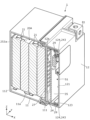
- FIG. 1 is a perspective view showing the appearance of a power storage device according to an embodiment.
- FIG. 2 is an exploded perspective view showing each component when the power storage device according to the embodiment is disassembled.
- FIG. 3 is a cross-sectional perspective view showing a joint structure between the exterior body and the power storage unit according to the embodiment.
- FIG. 4 is a cross-sectional perspective view showing a joint structure between an exterior body and a power storage unit according to Modification Example 1.
- a power storage device includes a power storage unit and an exterior body that houses the power storage unit, and the power storage unit includes a plurality of power storage elements arranged in a predetermined direction, It has a first holding member that is adjacent to the plurality of power storage elements in the predetermined direction and holds the plurality of power storage elements, and the first holding member is joined to the exterior body.
- the first holding member provided at the end of the power storage unit is joined to the exterior body, so the power storage unit is fixed at least on one side within the exterior body. It turns out. Thereby, the power storage unit becomes stable within the exterior body. Therefore, it is possible to improve the vibration resistance or impact resistance of the power storage device.
- the exterior body includes an exterior body having an opening at one end in the predetermined direction, and an exterior body that is attached to the one end of the exterior body and opens the opening. It may also have a closing exterior body lid.
- the power storage unit is housed in the exterior main body with one end opened in the predetermined direction, so the first holding member is attached to the other end of the power storage unit in the predetermined direction.
- the first holding member can be joined to the bottom of the exterior body main body. That is, when the power storage unit is housed in the exterior body main body, the first holding member provided at the other end of the power storage unit can be joined to the exterior body main body.
- the first holding member when the first holding member is disposed at one end of the power storage unit in a predetermined direction, the first holding member can be joined to the exterior body lid.
- the first holding member provided at one end of the power storage unit can be joined to the exterior body lid. In this way, it is possible to smoothly join the first holding member provided at the end of the power storage unit to the exterior body.
- the power storage unit further includes a second holding member that holds the plurality of power storage elements, and the second holding member is configured to hold the plurality of power storage elements.
- the power storage element may be disposed at a position sandwiching the plurality of power storage elements together with the first holding member in the direction of , and may be joined to the exterior body.
- the power storage device described in (3) above since the plurality of power storage elements are sandwiched and held by the first holding member and the second holding member, the first holding member and the second holding member The plurality of power storage elements become more stable within the exterior body. Furthermore, since the first holding member is joined to the exterior body and the second holding member is joined to the exterior body, the power storage unit is fixed on both sides within the exterior body. Thereby, it is possible to further improve the vibration resistance or impact resistance of the power storage device.
- a gap is formed between at least one of the first holding member and the second holding member and the exterior body at a position corresponding to the plurality of power storage elements.
- This gap can absorb the expansion of the plurality of power storage elements. Therefore, deformation of the exterior body due to expansion of the plurality of power storage elements can be suppressed.
- a circuit board may be disposed in the gap.
- the circuit board is disposed in the gap between at least one of the first holding member and the second holding member and the exterior body, a dedicated It is possible to accommodate a circuit board without providing any members. If a dedicated member is not required, the weight can be reduced, and the vibration resistance or impact resistance can thereby be further improved. Furthermore, if a dedicated member is not required, it is possible to save space within the exterior body, and the power storage device can be downsized.
- the direction in which the exterior body and the exterior cover of the exterior body of the power storage device are lined up, or the direction in which a plurality of power storage elements included in the power storage device are lined up is defined as the X-axis direction.
- the protruding direction of each lead terminal of the power storage element is defined as the Y-axis direction.
- the direction in which a pair of lead terminals provided on a power storage element are lined up or the vertical direction is defined as the Z-axis direction.
- the X-axis direction is an example of a predetermined direction.
- the Z-axis direction may not be the vertical direction, but for convenience of explanation, the Z-axis direction will be described as the vertical direction below.
- the X-axis plus direction refers to the arrow direction side of the X-axis
- the X-axis minus direction refers to the side opposite to the X-axis plus direction.
- Expressions indicating relative directions or orientations, such as parallel and orthogonal include cases where the directions or orientations are not strictly speaking. Two directions being orthogonal does not only mean that the two directions are completely orthogonal, but also that they are substantially orthogonal, that is, including a difference of a few percent. also means In the following description, when the expression "insulation" is used, it means “electrical insulation”.
- FIG. 1 is a perspective view showing the appearance of a power storage device 1 according to an embodiment.
- FIG. 2 is an exploded perspective view showing each component when power storage device 1 according to the embodiment is disassembled.
- the power storage device 1 is a device that can charge electricity from the outside and discharge electricity to the outside, and has a substantially rectangular parallelepiped shape in this embodiment.
- the power storage device 1 is a battery module (battery assembly) used for power storage, power supply, or the like.
- the power storage device 1 is a battery for driving or starting an engine of a moving object such as an automobile, a motorcycle, a watercraft, a ship, a snowmobile, an agricultural machine, a construction machine, or a railway vehicle for an electric railway. used as.
- Examples of the above-mentioned vehicles include electric vehicles (EVs), hybrid electric vehicles (HEVs), plug-in hybrid electric vehicles (PHEVs), and fossil fuel (gasoline, diesel oil, liquefied natural gas, etc.) vehicles.
- Examples of the above-mentioned railway vehicles for electric railways include electric trains, monorails, linear motor cars, and hybrid electric trains equipped with both a diesel engine and an electric motor.
- the power storage device 1 can also be used as a stationary battery or the like used for home or business purposes.
- the power storage device 1 includes a power storage unit 20 and an exterior body 10 that houses the power storage unit 20.
- the exterior body 10 includes an exterior body body 11 that accommodates the power storage unit 20, and an exterior body lid body 12 that closes the exterior body body 11.
- the exterior body 10 is a rectangular (box-shaped) container (module case) that constitutes the exterior body of the power storage device 1.
- the exterior body 10 is a member that fixes the power storage unit 20 and the like in a predetermined position and protects these elements from impact and the like.
- the exterior body 11 is a rectangular cylindrical member with a bottom that is open in the positive direction of the X-axis, and the open portion is the opening 111.
- the opening 111 has a substantially rectangular shape in plan view (as viewed in the X-axis direction).
- a plurality of bus bars (not shown) and fuses (not shown) held by the power storage unit 20 are accommodated in the opening 111 of the exterior body 11.
- the exterior lid 12 is a member that closes the opening 111 of the exterior body 11, and is joined to the exterior body 11 in a state where the opening 111 of the exterior body 11 is closed from the X-axis positive direction.
- a circuit board 35 is arranged at a position outside the opening 111 that corresponds to the exterior body lid 12 . That is, the circuit board 35 is accommodated between the exterior body 11 and the exterior body lid 12.
- the exterior lid 12 has a pair of external terminals 81 (a positive electrode and a negative electrode). External terminal 81 is electrically connected to a plurality of power storage elements 21 included in power storage unit 20 via each bus bar, fuse, and circuit board 35 . Power storage device 1 charges electricity from the outside via this external terminal 81 and discharges electricity to the outside.
- the external terminal 81 is made of a conductive member made of metal such as a copper alloy such as brass, copper, aluminum, or an aluminum alloy.
- Each bus bar is a plate-like member that electrically connects the external terminal 81 and the power storage element 21.
- Each bus bar is formed of a conductive member made of metal such as copper, copper alloy, aluminum, or aluminum alloy.
- the fuse is a member that protects the circuit board 35, the plurality of power storage elements 21, etc. from a large current exceeding the rated value. A fuse cuts off the flow of current by blowing when a current exceeding its rating flows.
- the circuit board 35 has a plurality of electrical components (not shown), and these electrical components form a detection circuit that detects the state (temperature, voltage, current, etc.) of each power storage element 21, and a detection circuit that controls charging and discharging. A control circuit and the like for control are formed.
- the circuit board 35 only needs to have at least one of a detection circuit and a control circuit.
- the exterior body 11 and exterior body lid 12 of the exterior body 10 are made of polycarbonate (PC), polypropylene (PP), polyethylene (PE), polystyrene (PS), polyphenylene sulfide resin (PPS), polyphenylene ether (PPE (modified PPE) )), polyethylene terephthalate (PET), polybutylene terephthalate (PBT), polyetheretherketone (PEEK), tetrafluoroethylene perfluoroalkyl vinyl ether (PFA), polytetrafluoroethylene (PTFE), polyethersal It is made of an insulating material such as PES (PES), polyamide (PA), ABS resin, or a composite material thereof, or metal coated with an insulating coating.
- PC polycarbonate
- PP polypropylene
- PE polyethylene
- PS polystyrene
- PPS polyphenylene sulfide resin
- PPE polyphenylene ether
- PET polyethylene terephthalate
- the exterior body 10 thereby prevents the power storage element 21 and the like from coming into contact with external metal members and the like.
- the exterior body 10 may be formed of a conductive member such as metal, as long as the electrical insulation of the power storage element 21 and the like is maintained.
- the exterior body 11 and the exterior body lid 12 may be formed of the same material or may be formed of different materials.
- the power storage unit 20 includes a plurality of power storage elements 21 and a holding section 22 that holds the plurality of power storage elements 21.
- the power storage element 21 is a secondary battery (single battery) that can charge and discharge electricity, and more specifically, it is a non-aqueous electrolyte secondary battery such as a lithium ion secondary battery.
- the power storage element 21 is a pouch-type power storage element having a flat shape, and a plurality of (four in this embodiment) pouch-type power storage elements 21 are arranged side by side in the X-axis direction. has been done.
- the power storage element 21 is not a pouch-type power storage element, but may be a flat rectangular parallelepiped (prismatic), cylindrical, long cylinder, or elliptical cylinder, and its size and shape are not limited.
- the number of power storage elements 21 arranged is also not particularly limited.
- the power storage element 21 is not limited to a non-aqueous electrolyte secondary battery, and may be a secondary battery other than a non-aqueous electrolyte secondary battery, or a capacitor.
- the power storage element 21 may be not a secondary battery but a primary battery that allows the user to use the stored electricity without charging it.
- the plurality of power storage elements 21 are arranged in the X-axis direction, and adjacent power storage elements 21 may or may not be joined with adhesive or double-sided tape. Details of the power storage element 21 will be described later.
- the holding part 22 is a part that holds a plurality of power storage elements 21.
- the holding portion 22 includes a holding member 23 and a holding member 24 that holds the plurality of power storage elements 21 together with the holding member 23.
- the holding member 23 is an example of a second holding member, and the holding member 24 is an example of a first holding member.
- the holding member 23 is arranged in the negative X-axis direction of the plurality of power storage elements 21, and is bonded to the power storage element 21 arranged at the end in the negative X-axis direction among the plurality of power storage elements 21. They are joined with adhesive or double-sided tape.
- the holding member 24 is arranged in the X-axis positive direction of the plurality of power storage elements 21, and is attached to the power storage element 21 arranged at the end in the X-axis positive direction among the plurality of power storage elements 21 with adhesive or double-sided tape. It is joined. Thereby, the holding member 23 and the holding member 24 hold the plurality of power storage elements 21 on both sides of the power storage elements 21 in the X-axis direction.
- the holding member 23 can hold the plurality of power storage elements 21 more stably by being arranged to face the center of the power storage elements 21 arranged at the ends in the negative X-axis direction. The same applies to the holding member 24.
- the central part of the power storage element 21 in the Z-axis direction is, for example, the middle three regions when the power storage element 21 is divided into five equal parts in the Z-axis direction, or the middle two regions when the power storage element 21 is divided into four equal parts. This is the area for one area in the middle when divided into three equal parts. The same applies to the Y-axis direction.
- At least one of the holding member 23 and the holding member 24 does not need to be joined to the power storage element 21. Even in this case, the holding members 23 and 24 can hold the plurality of power storage elements 21 by the clamping force received from the exterior body 11 and the exterior body lid 12. In addition to this, a plurality of power storage elements 21 may be held by extending a screw between the holding member 23 and the holding member 24 and tightening the screw.
- the holding member 23 and the holding member 24 are made of polycarbonate (PC), polypropylene (PP), polyethylene (PE), polyphenylene sulfide resin (PPS), polyphenylene ether (PPE (including modified PPE)), polyethylene terephthalate (PET), Polybutylene terephthalate (PBT), polyether ether ketone (PEEK), tetrafluoroethylene perfluoroalkyl vinyl ether (PFA), polytetrafluoroethylene (PTFE), polyether sulfone (PES), polyamide (PA), ABS resin , and an insulating member such as a composite material thereof.
- PC polycarbonate
- PP polypropylene
- PE polyethylene
- PPS polyphenylene sulfide resin
- PPE polyphenylene ether
- PET polyethylene terephthalate
- PBT Polybutylene terephthalate
- PEEK polyether ether ketone
- PTFE polytetrafluoro
- the holding member 23 has a flat plate portion 25 that overlaps the power storage element 21 at the end in the negative direction of the X-axis, and a bus bar support portion 26 that extends from the flat plate portion 25 in the positive direction of the X-axis.
- the bus bar support section 26 extends from the corner of the flat plate section 25 in the Y-axis minus direction and the Z-axis minus direction in the X-axis plus direction, and supports a bus bar (not shown).
- the holding member 24 has a substrate support portion 27 that overlaps the power storage element 21 at the end in the X-axis positive direction, and a detection line support portion 28 that extends from the substrate support portion 27 in the X-axis negative direction.
- the board support part 27 supports a circuit board 35 and has a surrounding wall 29 surrounding the circuit board 35. Further, the substrate support section 27 supports a bus bar and a fuse (not shown).
- the detection line support part 28 is a part that supports a plurality of detection lines 36 connected to the circuit board 35 in order to detect the state (temperature, voltage, current, etc.) of each power storage element 21.
- the detection line support section 28 extends from the end of the substrate support section 27 in the Y-axis minus direction in the X-axis minus direction.
- the plurality of power storage elements 21 have the same basic structure, but have partially different external shapes. Specifically, the outer shapes of the odd-numbered power storage elements 21 in order from the X-axis negative direction and the even-numbered power storage elements 21 in order from the X-axis negative direction are partially different. In other words, the odd-numbered power storage elements 21 have the same outer shape, and the even-numbered power storage elements 21 have the same outer shape.
- the power storage element 21 has an exterior film 210 and a pair of lead terminals 220 (positive electrode and negative electrode), and inside the exterior film 210, an electrode body (not shown) and an electrolyte (non-aqueous electrolyte: not shown) are provided. ) etc. are accommodated.
- an electrode body not shown
- an electrolyte non-aqueous electrolyte: not shown
- the exterior film 210 is a sheet-like exterior body formed of a laminate film, and contains an electrode body, an electrolytic solution, etc. therein in a sealed state under reduced pressure.
- the exterior film 210 is constructed by stacking two rectangular laminate films in the X-axis direction. The two laminate films are joined (sealed) by thermal welding or the like with a pair of lead terminals 220 in between. In the two laminate films, at locations that do not correspond to the pair of lead terminals 220, the two laminate films are joined (sealed) to each other by thermal welding or the like.
- Laminate film is a flexible film consisting of multiple layers including a metal layer such as aluminum and a resin layer such as polypropylene (PP) or polyethylene (PE). has been done.
- the exterior film 210 may be constructed by forming a single laminate film into a bag shape and joining the ends of the laminate film together by thermal welding.
- the lead terminal 220 is a conductive plate-like member (lead plate) that is electrically connected to the electrode body, and is disposed so as to penetrate through the exterior film 210 and be exposed from the exterior film 210.
- a pair of lead terminals 220 aligned in the Z-axis direction are arranged to protrude in the Y-axis minus direction from the end of the exterior film 210 in the Y-axis minus direction.
- the positive electrode lead terminal 220 is a lead terminal electrically connected to the positive electrode plate of the electrode body
- the negative electrode lead terminal 220 is a lead terminal electrically connected to the negative electrode plate of the electrode body. It is.
- the lead terminal 220 is a metal terminal for leading the electricity stored in the electrode body to the external space of the electricity storage element 21 and for introducing electricity into the internal space of the electricity storage element 21 to store electricity in the electrode body. It is an electrode terminal.
- the lead terminal 220 is made of aluminum, aluminum alloy, copper, copper alloy, or the like.
- the electrode body is a power storage element (power generation element) formed by laminating a positive electrode plate, a negative electrode plate, and a separator.
- the positive electrode plate has a positive electrode active material layer formed on a current collector foil made of metal such as aluminum or aluminum alloy.
- the negative electrode plate has a negative electrode active material layer formed on a current collector foil made of metal such as copper or copper alloy.
- the active material used for the positive electrode active material layer and the negative electrode active material layer any known material can be used as appropriate as long as it is capable of intercalating and deintercalating lithium ions.
- As the separator a microporous sheet made of resin, a nonwoven fabric, or the like can be used.
- the electrode body is formed by stacking electrode plates (a positive electrode plate and a negative electrode plate) in the X-axis direction.
- the electrode body is a wound type electrode body formed by winding electrode plates (positive electrode plate and negative electrode plate), and a laminated type (stack type) formed by laminating a plurality of flat electrode plates.
- Any form of electrode body may be used, such as a bellows-shaped electrode body in which an electrode plate is folded into a bellows shape.
- FIG. 3 is a cross-sectional perspective view showing a joint structure between the exterior body and the power storage unit according to the embodiment. Specifically, FIG. 3 is a cross-sectional perspective view taken along the line III--III in FIG. 1.
- a holding member 23 of the power storage unit 20 is joined to the exterior body 11 of the exterior body 10.
- a bottom frame 113 protruding in the positive direction of the X-axis is formed on an inner bottom surface 112 that faces the opening 111 in the X-axis direction.
- the bottom frame 113 is provided continuously or intermittently along the entire periphery of the inner bottom surface 112.
- the bottom frame 113 is arranged at a predetermined distance from the inner surface 11a of the exterior body main body 11.
- the flat plate portion 25 of the holding member 23 is provided with an edge portion 251 that extends continuously or intermittently along the entire circumference.
- the edge portion 251 protrudes from the flat plate portion 25 on both sides in the X-axis direction.
- a first groove 252 that extends continuously or intermittently over the entire circumference is formed on the end surface of the edge 251 in the negative X-axis direction.
- the bottom frame 113 is inserted into the first groove 252 with an adhesive 253 interposed therebetween.
- the first groove 252 and the bottom frame 113 are entirely or partially bonded together with an adhesive 253.
- a holding member 24 of the power storage unit 20 is joined to the exterior body lid 12 of the exterior body 10.
- a lid frame 123 protruding in the X-axis negative direction is formed on an inner top surface 121 that faces the opening 111 in the X-axis positive direction.
- the lid frame 123 is continuous in an annular shape within the inner top surface 121.
- the lid frame 123 is arranged at a predetermined distance from the inner surface 12a of the exterior lid 12.
- a second groove 124 is formed by the lid frame 123 and the inner surface 12a of the exterior lid 12.
- the tip portion (the end portion in the positive X-axis direction) of the surrounding wall 29 of the holding member 24 is inserted into the second groove 124 via the adhesive 243 .
- the surrounding wall 29 of the holding member 24 is bonded to the second groove 124 of the exterior body lid 12 over the entire circumference by being bonded with an adhesive 243.
- the power storage unit 20 is fixed on both sides within the exterior body 10 because the holding member 23 is joined to the exterior body 11 and the retaining member 24 is joined to the exterior body lid 12. Become. In this state, a gap S1 is formed between the substrate support portion 27 and the exterior body lid 12. The gap S1 is arranged at a position corresponding to the plurality of power storage elements 21 when viewed in the X-axis direction. That is, a gap S ⁇ b>1 is formed between the portion of the substrate support portion 27 facing the power storage element 21 and the exterior body lid 12 . Even if the plurality of power storage elements 21 expand, the expansion is absorbed by the gap S1, so that the expansion is difficult to be transmitted to the exterior body lid 12.
- a circuit board 35 is arranged inside the surrounding wall 29 within the gap S1. As described above, the tip of the surrounding wall 29 is adhered to the second groove 124 of the exterior body lid 12 over the entire circumference using the adhesive 243, so that the internal space of the surrounding wall 29 is sealed.
- the operator first applies adhesive 253 to the bottom frame 113 of the exterior body body 11 or the first groove 252 of the holding member 23. Thereafter, the operator arranges the power storage unit 20 in the positive direction of the X-axis of the exterior body 11 and moves the power storage unit 20 in the negative direction of the X-axis to house it in the exterior body 11 through the opening 111. .
- the bottom frame 113 is inserted into the first groove 252. As a result, the first groove 252 and the bottom frame 113 are bonded together with the adhesive 253.
- the operator applies adhesive 243 to the second groove 124 of the exterior lid 12 or the surrounding wall 29 of the holding member 24.
- the operator places the exterior body lid 12 in the X-axis positive direction of the exterior body body 11 and moves the exterior body lid 12 in the X-axis negative direction, thereby attaching the exterior body to the exterior body 11.
- the lid body 12 is assembled and glued.
- the surrounding wall 29 of the holding member 24 is inserted into the second groove 124.
- the second groove 124 and the surrounding wall 29 are bonded together with the adhesive 243. That is, the bonding between the exterior body 11 and the exterior body lid 12 and the bonding between the second groove 124 and the surrounding wall 29 are performed in the same process.
- the exterior film 210 of the power storage element 21 is formed of a flexible laminate film
- the power storage element 21 and the holding members 23 and 24 can be brought into closer contact with each other.
- the holding members 23 and 24 can firmly hold the power storage element 21.
- adjacent power storage elements 21 can be brought into closer contact with each other.
- the holding members 23 and 24 can firmly hold the plurality of power storage elements 21.
- the power storage unit 20 may be assembled to the exterior body 10 in a process opposite to the process described above. That is, after bonding the surrounding wall 29 of the holding member 24 to the second groove portion 124 of the outer case lid 12, the power storage unit 20 is inserted into the outer case main body 11, and the bottom frame 113 of the outer case main body 11 and the holding member 23 may be bonded to the first groove 232.
- the other end of the power storage unit 20 can be opened simply by housing the power storage unit 20 in the exterior body main body 11.
- the holding member 23 provided in the housing can be joined to the exterior body main body 11.
- the holding member 24 provided at one end of the power storage unit 20 can be joined to the exterior lid 12. In this way, the holding members 23 and 24 provided at the ends of the power storage unit 20 can be smoothly joined to the exterior body 10.
- the plurality of power storage elements 21 are held between the holding members 23 and 24, the plurality of power storage elements 21 are made more stable within the exterior body 10 by the holding members 23 and 24. Become. Furthermore, since the holding member 24 is joined to the exterior lid 12 and the holding member 23 is joined to the exterior body 11, the power storage unit 20 is fixed on both sides inside the exterior body 10. . Thereby, it is possible to further improve the vibration resistance or impact resistance of power storage device 1.
- a gap S1 is formed between the holding member 24 and the exterior lid 12 at a position corresponding to the plurality of power storage elements 21, so that the expansion of the plurality of power storage elements 21 can be absorbed by this gap S1. can. Therefore, deformation of the exterior body 10 due to expansion of the plurality of power storage elements 21 can be suppressed.
- the circuit board 35 is arranged in the gap S1, it is possible to accommodate the circuit board 35 without providing a dedicated member to cover the circuit board 35. If a dedicated member is not required, the weight can be reduced, and the vibration resistance or impact resistance can thereby be further improved. Furthermore, if a dedicated member is not required, it is possible to save space within the exterior body 10, and the power storage device 1 can be downsized.
- FIG. 4 is a cross-sectional perspective view showing a joint structure between an exterior body and a power storage unit according to Modification Example 1. Specifically, FIG. 4 is a diagram corresponding to FIG. 3.
- the power storage unit 20A has a holding member 24 that is a first holding member, but does not have a holding member 23 that is a second holding member. Therefore, the end of the power storage unit 20A in the negative X-axis direction is the first power storage element 21 in the negative direction of the X-axis.
- An adhesive 253a is interposed between this first power storage element 21 and the inner bottom surface 112 of the exterior body main body 11, and the power storage element 21 and the inner bottom surface 112 are bonded and joined. That is, also in this case, power storage unit 20A is fixed on both sides within exterior body 10.
- the holding member 24 is an example of the first holding member, and the holding member 23 is an example of the second holding member.
- the holding member 23 may be an example of a first holding member
- the holding member 24 may be an example of a second holding member.
- the holding member 24 can be removed as in Modification 1, and the fourth electricity storage element 21 can be joined (adhered) to the exterior body lid 12.
- the second holding member does not need to be joined to the exterior body. Also in this case, since the power storage unit is fixed on one side within the exterior body, the power storage unit is stabilized within the exterior body. Therefore, it is possible to improve the vibration resistance or impact resistance of the power storage device.
- adhesion is exemplified as a method for joining objects to be joined.
- the objects to be joined may be joined by a method other than adhesion.
- Other methods include welding, fixing with bolts and nuts, and the like.
- the gap S1 is formed between the substrate support part 27 of the holding member 24 and the exterior body lid 12 is illustrated.
- a gap may be provided between the holding member 23 and the inner bottom surface 112 of the exterior body main body 11. Even with this gap, expansion of the power storage element 21 can be absorbed, and deformation of the exterior body due to the expansion can be suppressed.
- the gap may be provided in at least one of the holding member 24 and the outer case lid 12 and between the holding member 23 and the outer case main body 11. Note that the gap may not be provided.
- the circuit board 35 is arranged in the gap S1 between the board support part 27 of the holding member 24 and the exterior body lid 12 is illustrated.
- the circuit board 35 may be placed in the gap. Note that the circuit board does not need to be placed within the gap.
- the exterior body main body 11 has an opening 111 at the end in the X-axis direction (predetermined direction), but the opening may be located in any position.
- the exterior body may have an opening at the end in the direction intersecting the X-axis direction.
- Embodiments constructed by arbitrarily combining components included in the embodiments and their modifications are also included within the scope of the present invention.
- the present invention can be applied to power storage devices and the like that include power storage elements such as lithium ion secondary batteries.
- Power storage device 10 Exterior body 11 Exterior body main bodies 11a, 12a Inner surface 12 Exterior body cover bodies 20, 20A Power storage unit 21 Power storage element 22 Holding part 23 Holding member (second holding member) 24 Holding member (first holding member) 25 Flat plate part 26 Bus bar support part 27 Board support part 28 Detection line support part 29 Surrounding wall 35 Circuit board 36 Detection line 81 External terminal 111 Opening 112 Inner bottom surface 113 Bottom frame 121 Inner top surface 123 Lid frame 124 Second groove 210 Exterior film 220 Lead terminals 243, 253, 253a Adhesive 251 Edge 252 First groove S1 Gap
Abstract
This power storage device comprises: a power storage unit; and a housing that accommodates the power storage unit. The power storage unit includes: a plurality of power storage elements arrayed in a prescribed direction; and a first holding member that is adjacent to the plurality of power storage elements in a prescribed direction and that holds the plurality of power storage elements. The first holding member is joined to the housing.
Description
本発明は、蓄電装置に関する。
The present invention relates to a power storage device.
特許文献1には、複数のパウチタイプのキャパシタセルをフレームに組み付けてユニット化した蓄電ユニットがハウジング内に収容された蓄電システムが開示されている。
Patent Document 1 discloses a power storage system in which a power storage unit, which is formed by assembling a plurality of pouch-type capacitor cells into a frame and forming a unit, is housed in a housing.
ここで、蓄電ユニットがハウジング内で移動してしまうと、蓄電ユニットがハウジングに衝突してしまい、損傷してしまうおそれがある。
Here, if the power storage unit moves within the housing, there is a risk that the power storage unit will collide with the housing and be damaged.
本発明は、本願発明者が上記課題に新たに着目することによってなされたものであり、蓄電装置の耐振動性または耐衝撃性を高めることを目的とする。
The present invention was achieved by the inventors of the present invention paying new attention to the above-mentioned problem, and aims to improve the vibration resistance or impact resistance of a power storage device.
本発明の一態様に係る蓄電装置は、蓄電ユニットと、前記蓄電ユニットを収容する外装体と、を備え、前記蓄電ユニットは、所定の方向に配列された複数の蓄電素子と、前記複数の蓄電素子に前記所定の方向で隣り合い当該複数の蓄電素子を保持する第一保持部材と、を有し、前記第一保持部材は前記外装体に接合されている。
A power storage device according to one aspect of the present invention includes a power storage unit and an exterior body that houses the power storage unit, and the power storage unit includes a plurality of power storage elements arranged in a predetermined direction and a plurality of power storage elements arranged in a predetermined direction. It has a first holding member that holds the plurality of power storage elements adjacent to the element in the predetermined direction, and the first holding member is joined to the exterior body.
本発明によれば、蓄電装置の耐振動性または耐衝撃性を高めることができる。
According to the present invention, the vibration resistance or impact resistance of a power storage device can be improved.
(1)本発明の一態様に係る蓄電装置は、蓄電ユニットと、前記蓄電ユニットを収容する外装体と、を備え、前記蓄電ユニットは、所定の方向に配列された複数の蓄電素子と、前記複数の蓄電素子に前記所定の方向で隣り合い当該複数の蓄電素子を保持する第一保持部材と、を有し、前記第一保持部材は前記外装体に接合されている。
(1) A power storage device according to one aspect of the present invention includes a power storage unit and an exterior body that houses the power storage unit, and the power storage unit includes a plurality of power storage elements arranged in a predetermined direction, It has a first holding member that is adjacent to the plurality of power storage elements in the predetermined direction and holds the plurality of power storage elements, and the first holding member is joined to the exterior body.
本発明の一態様に係る蓄電装置によれば、蓄電ユニットの端部に設けられた第一保持部材が、外装体と接合されているので、外装体内においては蓄電ユニットが少なくとも片側で固定されることになる。これにより、蓄電ユニットが外装体内で安定することになる。したがって、蓄電装置の耐振動性または耐衝撃性を高めることが可能である。
According to the power storage device according to one aspect of the present invention, the first holding member provided at the end of the power storage unit is joined to the exterior body, so the power storage unit is fixed at least on one side within the exterior body. It turns out. Thereby, the power storage unit becomes stable within the exterior body. Therefore, it is possible to improve the vibration resistance or impact resistance of the power storage device.
(2)上記(1)に記載の蓄電装置において、前記外装体は、前記所定の方向の一端部に開口を有する外装体本体と、前記外装体本体の前記一端部に取り付けられて前記開口を閉塞する外装体蓋体と、を有してもよい。
(2) In the power storage device according to (1) above, the exterior body includes an exterior body having an opening at one end in the predetermined direction, and an exterior body that is attached to the one end of the exterior body and opens the opening. It may also have a closing exterior body lid.
上記(2)に記載の蓄電装置によれば、所定の方向の一端部が開口した外装体本体に蓄電ユニットが収容されるので、蓄電ユニットの所定の方向の他端部に第一保持部材を配置した場合には、当該第一保持部材を外装体本体の底部に接合することができる。つまり、蓄電ユニットを外装体本体に収容する際に、当該蓄電ユニットの他端部に設けられた第一保持部材を外装体本体に接合できる。一方、蓄電ユニットの所定の方向の一端部に第一保持部材を配置した場合には、当該第一保持部材を外装体蓋体に接合することができる。つまり、外装体蓋体を外装体本体の一端部に取り付ける際に、蓄電ユニットの一端部に設けられた第一保持部材を外装体蓋体に接合できる。このように、蓄電ユニットの端部に備わる第一保持部材をスムーズに外装体に接合することが可能である。
According to the power storage device described in (2) above, the power storage unit is housed in the exterior main body with one end opened in the predetermined direction, so the first holding member is attached to the other end of the power storage unit in the predetermined direction. When arranged, the first holding member can be joined to the bottom of the exterior body main body. That is, when the power storage unit is housed in the exterior body main body, the first holding member provided at the other end of the power storage unit can be joined to the exterior body main body. On the other hand, when the first holding member is disposed at one end of the power storage unit in a predetermined direction, the first holding member can be joined to the exterior body lid. That is, when attaching the exterior body lid to one end of the exterior body main body, the first holding member provided at one end of the power storage unit can be joined to the exterior body lid. In this way, it is possible to smoothly join the first holding member provided at the end of the power storage unit to the exterior body.
(3)上記(1)または(2)に記載の蓄電装置において、前記蓄電ユニットは、さらに、前記複数の蓄電素子を保持する第二保持部材を有し、前記第二保持部材は、前記所定の方向において前記複数の蓄電素子を前記第一保持部材とともに挟む位置に配置され、前記外装体に接合されてもよい。
(3) In the power storage device according to (1) or (2) above, the power storage unit further includes a second holding member that holds the plurality of power storage elements, and the second holding member is configured to hold the plurality of power storage elements. The power storage element may be disposed at a position sandwiching the plurality of power storage elements together with the first holding member in the direction of , and may be joined to the exterior body.
上記(3)に記載の蓄電装置によれば、複数の蓄電素子が第一保持部材及び第二保持部材で挟まれて保持されているので、これらの第一保持部材及び第二保持部材により当該複数の蓄電素子が外装体内でより安定することになる。さらに、第一保持部材が外装体に接合されているとともに、第二保持部材が外装体に接合されているので、蓄電ユニットが外装体内の両側で固定されることになる。これにより、蓄電装置の耐振動性または耐衝撃性をより高めることが可能である。
According to the power storage device described in (3) above, since the plurality of power storage elements are sandwiched and held by the first holding member and the second holding member, the first holding member and the second holding member The plurality of power storage elements become more stable within the exterior body. Furthermore, since the first holding member is joined to the exterior body and the second holding member is joined to the exterior body, the power storage unit is fixed on both sides within the exterior body. Thereby, it is possible to further improve the vibration resistance or impact resistance of the power storage device.
(4)上記(3)に記載の蓄電装置において、前記第一保持部材及び前記第二保持部材の少なくとも一方と、前記外装体との間には、前記複数の蓄電素子に対応する位置に隙間が形成されてもよい。
(4) In the power storage device according to (3) above, there is a gap between at least one of the first holding member and the second holding member and the exterior body at a position corresponding to the plurality of power storage elements. may be formed.
上記(4)に記載の蓄電装置によれば、第一保持部材及び第二保持部材の少なくとも一方と外装体との間には、複数の蓄電素子に対応する位置に隙間が形成されているので、この隙間によって複数の蓄電素子の膨張を吸収できる。したがって、複数の蓄電素子の膨張を起因とした外装体の変形を抑制できる。
According to the power storage device described in (4) above, a gap is formed between at least one of the first holding member and the second holding member and the exterior body at a position corresponding to the plurality of power storage elements. This gap can absorb the expansion of the plurality of power storage elements. Therefore, deformation of the exterior body due to expansion of the plurality of power storage elements can be suppressed.
(5)上記(4)に記載の蓄電装置において、前記隙間には、回路基板が配置されてもよい。
(5) In the power storage device according to (4) above, a circuit board may be disposed in the gap.
上記(5)に記載の蓄電装置によれば、第一保持部材及び第二保持部材の少なくとも一方と外装体との間の隙間に、回路基板が配置されているので、回路基板を覆う専用の部材を設けなくとも回路基板を収容することが可能である。専用の部材が不要であれば軽量化でき、これにより耐振動性または耐衝撃性をより高めることができる。さらに専用の部材が不要であれば、外装体内の省スペース化も可能であり、蓄電装置を小型化できる。
According to the power storage device described in (5) above, since the circuit board is disposed in the gap between at least one of the first holding member and the second holding member and the exterior body, a dedicated It is possible to accommodate a circuit board without providing any members. If a dedicated member is not required, the weight can be reduced, and the vibration resistance or impact resistance can thereby be further improved. Furthermore, if a dedicated member is not required, it is possible to save space within the exterior body, and the power storage device can be downsized.
(実施の形態)
以下、図面を参照しながら、本発明の実施の形態(その変形例も含む)に係る蓄電装置について説明する。以下で説明する実施の形態は、いずれも包括的または具体的な例を示すものである。以下の実施の形態で示される数値、形状、材料、構成要素、構成要素の配置位置及び接続形態などは、一例であり、本発明を限定する主旨ではない。各図において、寸法等は厳密に図示したものではない。 (Embodiment)
Hereinafter, a power storage device according to an embodiment of the present invention (including variations thereof) will be described with reference to the drawings. The embodiments described below are all inclusive or specific examples. The numerical values, shapes, materials, components, arrangement positions and connection forms of the components shown in the following embodiments are merely examples, and do not limit the present invention. In each figure, dimensions etc. are not strictly illustrated.
以下の説明及び図面中において、蓄電装置の外装体における外装体本体と外装体蓋体との並び方向、または、蓄電装置に備わる複数の蓄電素子の並び方向をX軸方向と定義する。蓄電素子の各リード端子の突出方向をY軸方向と定義する。蓄電素子に備わる一対のリード端子の並び方向、または、上下方向をZ軸方向と定義する。X軸方向は所定の方向の一例である。これらX軸方向、Y軸方向及びZ軸方向は、互いに交差(以下実施の形態及びその変形例では、直交)する方向である。なお、使用態様によってはZ軸方向が上下方向にならない場合も考えられるが、以下では説明の便宜のため、Z軸方向を上下方向として説明する。以下の説明において、X軸プラス方向とは、X軸の矢印方向側を示し、X軸マイナス方向とは、X軸プラス方向とは反対側を示す。Y軸方向及びZ軸方向についても同様である。平行及び直交などの、相対的な方向または姿勢を示す表現は、厳密には、その方向または姿勢ではない場合も含む。2つの方向が直交している、とは、当該2つの方向が完全に直交していることを意味するだけでなく、実質的に直交していること、すなわち、数%程度の差異を含むことも意味する。以下の説明において、「絶縁」と表現する場合、「電気的な絶縁」を意味する。
In the following description and drawings, the direction in which the exterior body and the exterior cover of the exterior body of the power storage device are lined up, or the direction in which a plurality of power storage elements included in the power storage device are lined up is defined as the X-axis direction. The protruding direction of each lead terminal of the power storage element is defined as the Y-axis direction. The direction in which a pair of lead terminals provided on a power storage element are lined up or the vertical direction is defined as the Z-axis direction. The X-axis direction is an example of a predetermined direction. These X-axis direction, Y-axis direction, and Z-axis direction are directions that intersect with each other (orthogonal in the following embodiments and modifications thereof). Note that depending on the mode of use, the Z-axis direction may not be the vertical direction, but for convenience of explanation, the Z-axis direction will be described as the vertical direction below. In the following description, the X-axis plus direction refers to the arrow direction side of the X-axis, and the X-axis minus direction refers to the side opposite to the X-axis plus direction. The same applies to the Y-axis direction and the Z-axis direction. Expressions indicating relative directions or orientations, such as parallel and orthogonal, include cases where the directions or orientations are not strictly speaking. Two directions being orthogonal does not only mean that the two directions are completely orthogonal, but also that they are substantially orthogonal, that is, including a difference of a few percent. also means In the following description, when the expression "insulation" is used, it means "electrical insulation".
[蓄電装置の全般的な説明]
図1及び図2を用いて、実施の形態に係る蓄電装置1の全般的な説明を行う。図1は、実施の形態に係る蓄電装置1の外観を示す斜視図である。図2は、実施の形態に係る蓄電装置1を分解した場合の各構成要素を示す分解斜視図である。 [General explanation of power storage device]
A general description of thepower storage device 1 according to the embodiment will be given using FIGS. 1 and 2. FIG. 1 is a perspective view showing the appearance of a power storage device 1 according to an embodiment. FIG. 2 is an exploded perspective view showing each component when power storage device 1 according to the embodiment is disassembled.
図1及び図2を用いて、実施の形態に係る蓄電装置1の全般的な説明を行う。図1は、実施の形態に係る蓄電装置1の外観を示す斜視図である。図2は、実施の形態に係る蓄電装置1を分解した場合の各構成要素を示す分解斜視図である。 [General explanation of power storage device]
A general description of the
蓄電装置1は、外部からの電気を充電し、また外部へ電気を放電できる装置であり、本実施の形態では、略直方体形状を有している。蓄電装置1は、電力貯蔵用途または電源用途等に使用される電池モジュール(組電池)である。具体的には、蓄電装置1は、自動車、自動二輪車、ウォータークラフト、船舶、スノーモービル、農業機械、建設機械、電気鉄道用の鉄道車両等の移動体の駆動用またはエンジン始動用等のバッテリ等として用いられる。上記の自動車としては、電気自動車(EV)、ハイブリッド電気自動車(HEV)、プラグインハイブリッド電気自動車(PHEV)、及び、化石燃料(ガソリン、軽油、液化天然ガス等)自動車が例示される。上記の電気鉄道用の鉄道車両としては、電車、モノレール、リニアモーターカー、並びに、ディーゼル機関及び電気モーターの両方を備えるハイブリッド電車が例示される。また、蓄電装置1は、家庭用または事業用等に使用される定置用のバッテリ等としても用いることができる。
The power storage device 1 is a device that can charge electricity from the outside and discharge electricity to the outside, and has a substantially rectangular parallelepiped shape in this embodiment. The power storage device 1 is a battery module (battery assembly) used for power storage, power supply, or the like. Specifically, the power storage device 1 is a battery for driving or starting an engine of a moving object such as an automobile, a motorcycle, a watercraft, a ship, a snowmobile, an agricultural machine, a construction machine, or a railway vehicle for an electric railway. used as. Examples of the above-mentioned vehicles include electric vehicles (EVs), hybrid electric vehicles (HEVs), plug-in hybrid electric vehicles (PHEVs), and fossil fuel (gasoline, diesel oil, liquefied natural gas, etc.) vehicles. Examples of the above-mentioned railway vehicles for electric railways include electric trains, monorails, linear motor cars, and hybrid electric trains equipped with both a diesel engine and an electric motor. Furthermore, the power storage device 1 can also be used as a stationary battery or the like used for home or business purposes.
図1及び図2に示すように、蓄電装置1は、蓄電ユニット20と、蓄電ユニット20を収容する外装体10とを備えている。外装体10は、蓄電ユニット20を収容する外装体本体11と、外装体本体11を塞ぐ外装体蓋体12とを有する。
As shown in FIGS. 1 and 2, the power storage device 1 includes a power storage unit 20 and an exterior body 10 that houses the power storage unit 20. The exterior body 10 includes an exterior body body 11 that accommodates the power storage unit 20, and an exterior body lid body 12 that closes the exterior body body 11.
外装体10は、蓄電装置1の外装体を構成する矩形状(箱状)の容器(モジュールケース)である。つまり、外装体10は、蓄電ユニット20等を所定の位置に固定し、これら要素を衝撃などから保護する部材である。
The exterior body 10 is a rectangular (box-shaped) container (module case) that constitutes the exterior body of the power storage device 1. In other words, the exterior body 10 is a member that fixes the power storage unit 20 and the like in a predetermined position and protects these elements from impact and the like.
外装体本体11は、X軸プラス方向が開放された有底矩形筒状の部材であり、その開放部分が開口111である。開口111は、平面視(X軸方向視)において略四角形状である。外装体本体11の開口111内には、蓄電ユニット20に加えて、蓄電ユニット20に保持された複数のバスバー(図示省略)及びヒューズ(図示省略)が収容されている。
The exterior body 11 is a rectangular cylindrical member with a bottom that is open in the positive direction of the X-axis, and the open portion is the opening 111. The opening 111 has a substantially rectangular shape in plan view (as viewed in the X-axis direction). In addition to the power storage unit 20, a plurality of bus bars (not shown) and fuses (not shown) held by the power storage unit 20 are accommodated in the opening 111 of the exterior body 11.
外装体蓋体12は、外装体本体11の開口111を閉塞する部材であり、外装体本体11の開口111をX軸プラス方向から塞いだ状態で外装体本体11に接合されている。開口111外における外装体蓋体12に対応する位置には回路基板35が配置されている。つまり、外装体本体11と外装体蓋体12との間には回路基板35が収容されている。外装体蓋体12は、一対(正極及び負極)の外部端子81を有している。外部端子81は、各バスバー、ヒューズ及び回路基板35を介して、蓄電ユニット20に含まれる複数の蓄電素子21と電気的に接続されている。蓄電装置1は、この外部端子81を介して、外部からの電気を充電し、また外部へ電気を放電する。外部端子81は、真鍮などの銅合金、銅、アルミニウム、アルミニウム合金等の金属製の導電部材で形成されている。
The exterior lid 12 is a member that closes the opening 111 of the exterior body 11, and is joined to the exterior body 11 in a state where the opening 111 of the exterior body 11 is closed from the X-axis positive direction. A circuit board 35 is arranged at a position outside the opening 111 that corresponds to the exterior body lid 12 . That is, the circuit board 35 is accommodated between the exterior body 11 and the exterior body lid 12. The exterior lid 12 has a pair of external terminals 81 (a positive electrode and a negative electrode). External terminal 81 is electrically connected to a plurality of power storage elements 21 included in power storage unit 20 via each bus bar, fuse, and circuit board 35 . Power storage device 1 charges electricity from the outside via this external terminal 81 and discharges electricity to the outside. The external terminal 81 is made of a conductive member made of metal such as a copper alloy such as brass, copper, aluminum, or an aluminum alloy.
各バスバーは、外部端子81と蓄電素子21とを電気的に接続する板状部材である。各バスバーは、銅、銅合金、アルミニウム、アルミニウム合金等の金属製の導電部材で形成されている。
Each bus bar is a plate-like member that electrically connects the external terminal 81 and the power storage element 21. Each bus bar is formed of a conductive member made of metal such as copper, copper alloy, aluminum, or aluminum alloy.
ヒューズは、定格以上の大電流から回路基板35及び複数の蓄電素子21等を保護する部材である。ヒューズは、定格以上の電流が流れると溶断することで電流の流れを遮断する。
The fuse is a member that protects the circuit board 35, the plurality of power storage elements 21, etc. from a large current exceeding the rated value. A fuse cuts off the flow of current by blowing when a current exceeding its rating flows.
回路基板35は、複数の電気部品(図示省略)を有し、これら複数の電気部品により、各蓄電素子21の状態(温度、電圧、電流など)を検出する検出回路、及び、充電及び放電を制御する制御回路等が形成されている。回路基板35は、検出回路及び制御回路の少なくとも一方を有していればよい。
The circuit board 35 has a plurality of electrical components (not shown), and these electrical components form a detection circuit that detects the state (temperature, voltage, current, etc.) of each power storage element 21, and a detection circuit that controls charging and discharging. A control circuit and the like for control are formed. The circuit board 35 only needs to have at least one of a detection circuit and a control circuit.
外装体10の外装体本体11及び外装体蓋体12は、ポリカーボネート(PC)、ポリプロピレン(PP)、ポリエチレン(PE)、ポリスチレン(PS)、ポリフェニレンサルファイド樹脂(PPS)、ポリフェニレンエーテル(PPE(変性PPEを含む))、ポリエチレンテレフタラート(PET)、ポリブチレンテレフタレート(PBT)、ポリエーテルエーテルケトン(PEEK)、テトラフルオロエチレン・パーフルオロアルキルビニルエーテル(PFA)、ポリテトラフルオロエチレン(PTFE)、ポリエーテルサルフォン(PES)、ポリアミド(PA)、ABS樹脂、若しくは、それらの複合材料等の絶縁部材、絶縁塗装をした金属等により形成されている。外装体10は、これにより、蓄電素子21等が外部の金属部材等に接触することを回避する。なお、蓄電素子21等の電気的絶縁性が保たれる構成であれば、外装体10は、金属等の導電部材で形成されていてもよい。外装体本体11及び外装体蓋体12は、同じ材質で形成されてもよいし、異なる材質で形成されてもよい。
The exterior body 11 and exterior body lid 12 of the exterior body 10 are made of polycarbonate (PC), polypropylene (PP), polyethylene (PE), polystyrene (PS), polyphenylene sulfide resin (PPS), polyphenylene ether (PPE (modified PPE) )), polyethylene terephthalate (PET), polybutylene terephthalate (PBT), polyetheretherketone (PEEK), tetrafluoroethylene perfluoroalkyl vinyl ether (PFA), polytetrafluoroethylene (PTFE), polyethersal It is made of an insulating material such as PES (PES), polyamide (PA), ABS resin, or a composite material thereof, or metal coated with an insulating coating. The exterior body 10 thereby prevents the power storage element 21 and the like from coming into contact with external metal members and the like. Note that the exterior body 10 may be formed of a conductive member such as metal, as long as the electrical insulation of the power storage element 21 and the like is maintained. The exterior body 11 and the exterior body lid 12 may be formed of the same material or may be formed of different materials.
[蓄電ユニット]
蓄電ユニット20は、複数の蓄電素子21と、これらの複数の蓄電素子21を保持する保持部22とを備えている。 [Electricity storage unit]
Thepower storage unit 20 includes a plurality of power storage elements 21 and a holding section 22 that holds the plurality of power storage elements 21.
蓄電ユニット20は、複数の蓄電素子21と、これらの複数の蓄電素子21を保持する保持部22とを備えている。 [Electricity storage unit]
The
蓄電素子21は、電気を充電し、また、電気を放電できる二次電池(単電池)であり、より具体的には、リチウムイオン二次電池等の非水電解質二次電池である。本実施の形態では、蓄電素子21は、扁平な形状を有するパウチタイプの蓄電素子であり、複数(本実施の形態では、4個)のパウチタイプの蓄電素子21がX軸方向に並んで配列されている。蓄電素子21は、パウチタイプの蓄電素子ではなく、扁平な直方体形状(角形)、円柱形状、長円柱形状または楕円柱形状等の蓄電素子でもよく、その大きさ及び形状は限定されない。配列される蓄電素子21の個数についても、特に限定されない。蓄電素子21は、非水電解質二次電池には限定されず、非水電解質二次電池以外の二次電池であってもよいし、キャパシタであってもよい。蓄電素子21は、二次電池ではなく、使用者が充電をしなくても蓄えられている電気を使用できる一次電池であってもよい。複数の蓄電素子21は、X軸方向に配列されており、隣り合う蓄電素子21同士が接着剤または両面テープにより接合されてもよいし、接合されなくてもよい。蓄電素子21の詳細については後述する。
The power storage element 21 is a secondary battery (single battery) that can charge and discharge electricity, and more specifically, it is a non-aqueous electrolyte secondary battery such as a lithium ion secondary battery. In this embodiment, the power storage element 21 is a pouch-type power storage element having a flat shape, and a plurality of (four in this embodiment) pouch-type power storage elements 21 are arranged side by side in the X-axis direction. has been done. The power storage element 21 is not a pouch-type power storage element, but may be a flat rectangular parallelepiped (prismatic), cylindrical, long cylinder, or elliptical cylinder, and its size and shape are not limited. The number of power storage elements 21 arranged is also not particularly limited. The power storage element 21 is not limited to a non-aqueous electrolyte secondary battery, and may be a secondary battery other than a non-aqueous electrolyte secondary battery, or a capacitor. The power storage element 21 may be not a secondary battery but a primary battery that allows the user to use the stored electricity without charging it. The plurality of power storage elements 21 are arranged in the X-axis direction, and adjacent power storage elements 21 may or may not be joined with adhesive or double-sided tape. Details of the power storage element 21 will be described later.
保持部22は、複数の蓄電素子21を保持する部位である。保持部22は、保持部材23と、保持部材23とともに複数の蓄電素子21を保持する保持部材24とを有している。保持部材23は第二保持部材の一例であり、保持部材24は第一保持部材の一例である。具体的には、保持部材23は、複数の蓄電素子21のX軸マイナス方向に配置されており、複数の蓄電素子21のうち、X軸マイナス方向の端部に配置された蓄電素子21に接着剤または両面テープにより接合されている。保持部材24は、複数の蓄電素子21のX軸プラス方向に配置されており、複数の蓄電素子21のうち、X軸プラス方向の端部に配置された蓄電素子21に接着剤または両面テープにより接合されている。これにより、保持部材23及び保持部材24は、複数の蓄電素子21をX軸方向で挟んで保持している。保持部材23は、X軸マイナス方向の端部に配置された蓄電素子21の中央部に対向して配置されることで、複数の蓄電素子21をより安定して保持できる。保持部材24についても同様である。ここで、Z軸方向における蓄電素子21の中央部とは、例えば、Z軸方向に蓄電素子21を5等分した場合の中間の3つ分の領域、4等分した場合の中間の2つ分の領域、3等分した場合の中間の1つ分の領域である。Y軸方向についても同様である。
The holding part 22 is a part that holds a plurality of power storage elements 21. The holding portion 22 includes a holding member 23 and a holding member 24 that holds the plurality of power storage elements 21 together with the holding member 23. The holding member 23 is an example of a second holding member, and the holding member 24 is an example of a first holding member. Specifically, the holding member 23 is arranged in the negative X-axis direction of the plurality of power storage elements 21, and is bonded to the power storage element 21 arranged at the end in the negative X-axis direction among the plurality of power storage elements 21. They are joined with adhesive or double-sided tape. The holding member 24 is arranged in the X-axis positive direction of the plurality of power storage elements 21, and is attached to the power storage element 21 arranged at the end in the X-axis positive direction among the plurality of power storage elements 21 with adhesive or double-sided tape. It is joined. Thereby, the holding member 23 and the holding member 24 hold the plurality of power storage elements 21 on both sides of the power storage elements 21 in the X-axis direction. The holding member 23 can hold the plurality of power storage elements 21 more stably by being arranged to face the center of the power storage elements 21 arranged at the ends in the negative X-axis direction. The same applies to the holding member 24. Here, the central part of the power storage element 21 in the Z-axis direction is, for example, the middle three regions when the power storage element 21 is divided into five equal parts in the Z-axis direction, or the middle two regions when the power storage element 21 is divided into four equal parts. This is the area for one area in the middle when divided into three equal parts. The same applies to the Y-axis direction.
保持部材23及び保持部材24の少なくとも一方は、蓄電素子21に接合されていなくてもよい。この場合においても、外装体本体11及び外装体蓋体12から受ける挟持力で保持部材23及び保持部材24は複数の蓄電素子21を保持することが可能である。これ以外にも、保持部材23及び保持部材24の間にネジを架け渡して締め付けることで、複数の蓄電素子21を保持してもよい。
At least one of the holding member 23 and the holding member 24 does not need to be joined to the power storage element 21. Even in this case, the holding members 23 and 24 can hold the plurality of power storage elements 21 by the clamping force received from the exterior body 11 and the exterior body lid 12. In addition to this, a plurality of power storage elements 21 may be held by extending a screw between the holding member 23 and the holding member 24 and tightening the screw.
保持部材23及び保持部材24は、ポリカーボネート(PC)、ポリプロピレン(PP)、ポリエチレン(PE)、ポリフェニレンサルファイド樹脂(PPS)、ポリフェニレンエーテル(PPE(変性PPEを含む))、ポリエチレンテレフタラート(PET)、ポリブチレンテレフタレート(PBT)、ポリエーテルエーテルケトン(PEEK)、テトラフルオロエチレン・パーフルオロアルキルビニルエーテル(PFA)、ポリテトラフルオロエチレン(PTFE)、ポリエーテルサルフォン(PES)、ポリアミド(PA)、ABS樹脂、それらの複合材料等の絶縁部材により形成されている。これにより、保持部材23及び保持部材24は、複数の蓄電素子21が外部の金属部材等の導電部材と導通することを抑制するが、そのような必要がない場合等には、保持部材23及び保持部材24は、金属等の導電部材で形成されてもよい。
The holding member 23 and the holding member 24 are made of polycarbonate (PC), polypropylene (PP), polyethylene (PE), polyphenylene sulfide resin (PPS), polyphenylene ether (PPE (including modified PPE)), polyethylene terephthalate (PET), Polybutylene terephthalate (PBT), polyether ether ketone (PEEK), tetrafluoroethylene perfluoroalkyl vinyl ether (PFA), polytetrafluoroethylene (PTFE), polyether sulfone (PES), polyamide (PA), ABS resin , and an insulating member such as a composite material thereof. As a result, the holding member 23 and the holding member 24 prevent the plurality of power storage elements 21 from being electrically connected to a conductive member such as an external metal member. The holding member 24 may be formed of a conductive member such as metal.
保持部材23は、X軸マイナス方向の端部の蓄電素子21に重なる平板部25と、平板部25からX軸プラス方向に延びるバスバー支持部26とを有している。バスバー支持部26は、平板部25のY軸マイナス方向、Z軸マイナス方向の角部からX軸プラス方向に延びており、図示しないバスバーを支持している。
The holding member 23 has a flat plate portion 25 that overlaps the power storage element 21 at the end in the negative direction of the X-axis, and a bus bar support portion 26 that extends from the flat plate portion 25 in the positive direction of the X-axis. The bus bar support section 26 extends from the corner of the flat plate section 25 in the Y-axis minus direction and the Z-axis minus direction in the X-axis plus direction, and supports a bus bar (not shown).
保持部材24は、X軸プラス方向の端部の蓄電素子21に重なる基板支持部27と、基板支持部27からX軸マイナス方向に延びる検出線支持部28とを有している。基板支持部27は、回路基板35を支持しており、当該回路基板35を囲む囲壁29を有している。また、基板支持部27は、図示しないバスバー及びヒューズを支持している。
The holding member 24 has a substrate support portion 27 that overlaps the power storage element 21 at the end in the X-axis positive direction, and a detection line support portion 28 that extends from the substrate support portion 27 in the X-axis negative direction. The board support part 27 supports a circuit board 35 and has a surrounding wall 29 surrounding the circuit board 35. Further, the substrate support section 27 supports a bus bar and a fuse (not shown).
検出線支持部28は、各蓄電素子21の状態(温度、電圧、電流など)を検出するために、回路基板35に接続された複数の検出線36を支持する部位である。検出線支持部28は、基板支持部27のY軸マイナス方向の端部からX軸マイナス方向に延びている。
The detection line support part 28 is a part that supports a plurality of detection lines 36 connected to the circuit board 35 in order to detect the state (temperature, voltage, current, etc.) of each power storage element 21. The detection line support section 28 extends from the end of the substrate support section 27 in the Y-axis minus direction in the X-axis minus direction.
[蓄電素子]
蓄電素子21の詳細について説明する。図2に示すように、複数の蓄電素子21は、基本的な構造は同様であるものの、外形形状が部分的に異なる。具体的には、X軸マイナス方向から順に奇数番目の蓄電素子21と、X軸マイナス方向から順に偶数番目の蓄電素子21とで、外形形状が部分的に異なっている。つまり、奇数番目の蓄電素子21同士は外形形状が同等であり、偶数番目の蓄電素子21同士は外形形状が同等である。 [Electricity storage element]
Details of thepower storage element 21 will be explained. As shown in FIG. 2, the plurality of power storage elements 21 have the same basic structure, but have partially different external shapes. Specifically, the outer shapes of the odd-numbered power storage elements 21 in order from the X-axis negative direction and the even-numbered power storage elements 21 in order from the X-axis negative direction are partially different. In other words, the odd-numbered power storage elements 21 have the same outer shape, and the even-numbered power storage elements 21 have the same outer shape.
蓄電素子21の詳細について説明する。図2に示すように、複数の蓄電素子21は、基本的な構造は同様であるものの、外形形状が部分的に異なる。具体的には、X軸マイナス方向から順に奇数番目の蓄電素子21と、X軸マイナス方向から順に偶数番目の蓄電素子21とで、外形形状が部分的に異なっている。つまり、奇数番目の蓄電素子21同士は外形形状が同等であり、偶数番目の蓄電素子21同士は外形形状が同等である。 [Electricity storage element]
Details of the
蓄電素子21の基本的な構造について説明する。蓄電素子21は、外装フィルム210と、一対(正極及び負極)のリード端子220とを有し、外装フィルム210の内方には、電極体(図示省略)及び電解液(非水電解質:図示省略)等が収容されている。当該電解液としては、蓄電素子21の性能を損なうものでなければその種類に特に制限はなく、適宜公知の材料を用いることができる。
The basic structure of the power storage element 21 will be explained. The power storage element 21 has an exterior film 210 and a pair of lead terminals 220 (positive electrode and negative electrode), and inside the exterior film 210, an electrode body (not shown) and an electrolyte (non-aqueous electrolyte: not shown) are provided. ) etc. are accommodated. There is no particular restriction on the type of the electrolytic solution as long as it does not impair the performance of the power storage element 21, and any known material can be used as appropriate.
外装フィルム210は、ラミネートフィルムで形成されたシート状の外装体であり、内部に電極体及び電解液等を減圧状態で密閉して収容している。外装フィルム210は、矩形状の2枚のラミネートフィルムが、X軸方向に重ねられて構成されている。当該2枚のラミネートフィルムは、一対のリード端子220を挟んで熱溶着等により接合(シール)されている。2枚のラミネートフィルムにおいて、一対のリード端子220に対応しない箇所では、当該2枚のラミネートフィルム同士が熱溶着等により接合(シール)されている。ラミネートフィルムは、アルミニウム等の金属層と、ポリプロピレン(PP)またはポリエチレン(PE)等の樹脂層とを含む複数層からなるフレキシブルなフィルムであり、溶着箇所(シール部)には、樹脂層が配置されている。外装フィルム210は、1枚のラミネートフィルムを袋状に形成して、当該ラミネートフィルムの端部同士を熱溶着により接合することで構成されてもよい。
The exterior film 210 is a sheet-like exterior body formed of a laminate film, and contains an electrode body, an electrolytic solution, etc. therein in a sealed state under reduced pressure. The exterior film 210 is constructed by stacking two rectangular laminate films in the X-axis direction. The two laminate films are joined (sealed) by thermal welding or the like with a pair of lead terminals 220 in between. In the two laminate films, at locations that do not correspond to the pair of lead terminals 220, the two laminate films are joined (sealed) to each other by thermal welding or the like. Laminate film is a flexible film consisting of multiple layers including a metal layer such as aluminum and a resin layer such as polypropylene (PP) or polyethylene (PE). has been done. The exterior film 210 may be constructed by forming a single laminate film into a bag shape and joining the ends of the laminate film together by thermal welding.
リード端子220は、電極体に電気的に接続された導電性の板状部材(リード板)であり、外装フィルム210を貫通した状態で外装フィルム210から露出して配置されている。本実施の形態では、Z軸方向に並ぶ一対のリード端子220が、外装フィルム210のY軸マイナス方向の端部からY軸マイナス方向に突出して配置されている。具体的には、正極のリード端子220は、電極体の正極板に電気的に接続されたリード端子であり、負極のリード端子220は、電極体の負極板に電気的に接続されたリード端子である。リード端子220は、電極体に蓄えられている電気を蓄電素子21の外部空間に導出し、また、電極体に電気を蓄えるために蓄電素子21の内部空間に電気を導入するための金属製の電極端子である。リード端子220は、アルミニウム、アルミニウム合金、銅、銅合金等で形成されている。
The lead terminal 220 is a conductive plate-like member (lead plate) that is electrically connected to the electrode body, and is disposed so as to penetrate through the exterior film 210 and be exposed from the exterior film 210. In this embodiment, a pair of lead terminals 220 aligned in the Z-axis direction are arranged to protrude in the Y-axis minus direction from the end of the exterior film 210 in the Y-axis minus direction. Specifically, the positive electrode lead terminal 220 is a lead terminal electrically connected to the positive electrode plate of the electrode body, and the negative electrode lead terminal 220 is a lead terminal electrically connected to the negative electrode plate of the electrode body. It is. The lead terminal 220 is a metal terminal for leading the electricity stored in the electrode body to the external space of the electricity storage element 21 and for introducing electricity into the internal space of the electricity storage element 21 to store electricity in the electrode body. It is an electrode terminal. The lead terminal 220 is made of aluminum, aluminum alloy, copper, copper alloy, or the like.
電極体は、正極板と負極板とセパレータとが積層されて形成された蓄電要素(発電要素)である。正極板は、アルミニウムまたはアルミニウム合金等の金属からなる集電箔上に正極活物質層が形成されたものである。負極板は、銅または銅合金等の金属からなる集電箔上に負極活物質層が形成されたものである。正極活物質層及び負極活物質層に用いられる活物質としては、リチウムイオンを吸蔵放出可能なものであれば、適宜公知の材料を使用できる。セパレータは、樹脂からなる微多孔性のシートまたは不織布等を用いることができる。本実施の形態では、電極体は、極板(正極板及び負極板)がX軸方向に積層されて形成されている。なお、電極体は、極板(正極板及び負極板)が巻回されて形成された巻回型の電極体、複数の平板状の極板が積層されて形成された積層型(スタック型)の電極体、極板を蛇腹状に折り畳んだ蛇腹型の電極体等、どのような形態の電極体でもよい。
The electrode body is a power storage element (power generation element) formed by laminating a positive electrode plate, a negative electrode plate, and a separator. The positive electrode plate has a positive electrode active material layer formed on a current collector foil made of metal such as aluminum or aluminum alloy. The negative electrode plate has a negative electrode active material layer formed on a current collector foil made of metal such as copper or copper alloy. As the active material used for the positive electrode active material layer and the negative electrode active material layer, any known material can be used as appropriate as long as it is capable of intercalating and deintercalating lithium ions. As the separator, a microporous sheet made of resin, a nonwoven fabric, or the like can be used. In this embodiment, the electrode body is formed by stacking electrode plates (a positive electrode plate and a negative electrode plate) in the X-axis direction. In addition, the electrode body is a wound type electrode body formed by winding electrode plates (positive electrode plate and negative electrode plate), and a laminated type (stack type) formed by laminating a plurality of flat electrode plates. Any form of electrode body may be used, such as a bellows-shaped electrode body in which an electrode plate is folded into a bellows shape.
[外装体と蓄電ユニットとの接合構造]
外装体10と蓄電ユニット20の接合構造について説明する。図3は、実施の形態に係る外装体と蓄電ユニットとの接合構造を示す断面斜視図である。具体的には、図3は、図1におけるIII-III線を含む切断面を見た断面斜視図である。 [Joining structure between exterior body and power storage unit]
The joining structure between theexterior body 10 and the power storage unit 20 will be explained. FIG. 3 is a cross-sectional perspective view showing a joint structure between the exterior body and the power storage unit according to the embodiment. Specifically, FIG. 3 is a cross-sectional perspective view taken along the line III--III in FIG. 1.
外装体10と蓄電ユニット20の接合構造について説明する。図3は、実施の形態に係る外装体と蓄電ユニットとの接合構造を示す断面斜視図である。具体的には、図3は、図1におけるIII-III線を含む切断面を見た断面斜視図である。 [Joining structure between exterior body and power storage unit]
The joining structure between the
図3に示すように、外装体10の外装体本体11には、蓄電ユニット20の保持部材23が接合されている。具体的には、外装体本体11は、開口111にX軸方向で対向する内底面112に、X軸プラス方向に突出した底枠113が形成されている。底枠113は、内底面112の全周縁に沿って連続的または断続的に設けられている。底枠113は、外装体本体11の内側面11aから所定の間隔をあけて配置されている。
As shown in FIG. 3, a holding member 23 of the power storage unit 20 is joined to the exterior body 11 of the exterior body 10. Specifically, in the exterior main body 11, a bottom frame 113 protruding in the positive direction of the X-axis is formed on an inner bottom surface 112 that faces the opening 111 in the X-axis direction. The bottom frame 113 is provided continuously or intermittently along the entire periphery of the inner bottom surface 112. The bottom frame 113 is arranged at a predetermined distance from the inner surface 11a of the exterior body main body 11.
保持部材23の平板部25の周縁には、全周にわたって連続的または断続的に沿う縁部251が設けられている。縁部251は、平板部25に対してX軸方向の両側で突出している。縁部251のX軸マイナス方向の端面には、全周にわたって連続的または断続的に沿う第一溝252が形成されている。この第一溝252内には接着剤253を介して、底枠113が挿入される。第一溝252と底枠113とは全体的にまたは部分的に接着剤253で接着されることで接合されている。
The flat plate portion 25 of the holding member 23 is provided with an edge portion 251 that extends continuously or intermittently along the entire circumference. The edge portion 251 protrudes from the flat plate portion 25 on both sides in the X-axis direction. A first groove 252 that extends continuously or intermittently over the entire circumference is formed on the end surface of the edge 251 in the negative X-axis direction. The bottom frame 113 is inserted into the first groove 252 with an adhesive 253 interposed therebetween. The first groove 252 and the bottom frame 113 are entirely or partially bonded together with an adhesive 253.
外装体10の外装体蓋体12には、蓄電ユニット20の保持部材24が接合されている。具体的には、外装体蓋体12は、開口111にX軸プラス方向で対向する内天面121に、X軸マイナス方向に突出した蓋枠123が形成されている。蓋枠123は、内天面121内において環状に連続している。蓋枠123は、外装体蓋体12の内側面12aから所定の間隔をあけて配置されている。蓋枠123と外装体蓋体12の内側面12aとにより第二溝124が形成されている。第二溝124内には、保持部材24の囲壁29の先端部(X軸プラス方向の端部)が接着剤243を介して挿入される。保持部材24の囲壁29は、全周にわたって外装体蓋体12の第二溝124に接着剤243で接着されることで接合されている。
A holding member 24 of the power storage unit 20 is joined to the exterior body lid 12 of the exterior body 10. Specifically, in the exterior body lid 12, a lid frame 123 protruding in the X-axis negative direction is formed on an inner top surface 121 that faces the opening 111 in the X-axis positive direction. The lid frame 123 is continuous in an annular shape within the inner top surface 121. The lid frame 123 is arranged at a predetermined distance from the inner surface 12a of the exterior lid 12. A second groove 124 is formed by the lid frame 123 and the inner surface 12a of the exterior lid 12. The tip portion (the end portion in the positive X-axis direction) of the surrounding wall 29 of the holding member 24 is inserted into the second groove 124 via the adhesive 243 . The surrounding wall 29 of the holding member 24 is bonded to the second groove 124 of the exterior body lid 12 over the entire circumference by being bonded with an adhesive 243.
このように、蓄電ユニット20は、保持部材23が外装体本体11に接合されるとともに保持部材24が外装体蓋体12に接合されているので、外装体10内では両側で固定された状態となる。この状態では、基板支持部27と外装体蓋体12との間に隙間S1が形成される。隙間S1は、X軸方向視で複数の蓄電素子21に対応する位置に配置されている。つまり、基板支持部27の蓄電素子21と対向する部分と外装体蓋体12との間に隙間S1が形成される。複数の蓄電素子21が膨張したとしてもその膨張を隙間S1が吸収するので、当該膨張が外装体蓋体12に伝わりにくくなっている。隙間S1内において囲壁29の内方には回路基板35が配置されている。上述したように、囲壁29の先端部は、全周にわたって外装体蓋体12の第二溝124に接着剤243により接着されているので、囲壁29の内部空間が密閉されている。
In this way, the power storage unit 20 is fixed on both sides within the exterior body 10 because the holding member 23 is joined to the exterior body 11 and the retaining member 24 is joined to the exterior body lid 12. Become. In this state, a gap S1 is formed between the substrate support portion 27 and the exterior body lid 12. The gap S1 is arranged at a position corresponding to the plurality of power storage elements 21 when viewed in the X-axis direction. That is, a gap S<b>1 is formed between the portion of the substrate support portion 27 facing the power storage element 21 and the exterior body lid 12 . Even if the plurality of power storage elements 21 expand, the expansion is absorbed by the gap S1, so that the expansion is difficult to be transmitted to the exterior body lid 12. A circuit board 35 is arranged inside the surrounding wall 29 within the gap S1. As described above, the tip of the surrounding wall 29 is adhered to the second groove 124 of the exterior body lid 12 over the entire circumference using the adhesive 243, so that the internal space of the surrounding wall 29 is sealed.
製造時、外装体10に蓄電ユニット20を組み付ける際には、まず、作業者は、外装体本体11の底枠113または保持部材23の第一溝252に接着剤253をつける。その後、作業者は、外装体本体11のX軸プラス方向に蓄電ユニット20を配置して、当該蓄電ユニット20をX軸マイナス方向に移動させることで、開口111から外装体本体11内に収容する。この収容時に、第一溝252内に底枠113が挿入される。これにより、第一溝252と底枠113とが接着剤253で接着される。
During manufacturing, when assembling the power storage unit 20 to the exterior body 10, the operator first applies adhesive 253 to the bottom frame 113 of the exterior body body 11 or the first groove 252 of the holding member 23. Thereafter, the operator arranges the power storage unit 20 in the positive direction of the X-axis of the exterior body 11 and moves the power storage unit 20 in the negative direction of the X-axis to house it in the exterior body 11 through the opening 111. . During this accommodation, the bottom frame 113 is inserted into the first groove 252. As a result, the first groove 252 and the bottom frame 113 are bonded together with the adhesive 253.
次いで、作業者は、外装体蓋体12の第二溝124または保持部材24の囲壁29に接着剤243をつける。その後、作業者は、外装体本体11のX軸プラス方向に外装体蓋体12を配置して、当該外装体蓋体12をX軸マイナス方向に移動させることで、外装体本体11に外装体蓋体12を組み付けて接着する。このとき、第二溝124内に、保持部材24の囲壁29が挿入される。これにより、第二溝124と囲壁29とが接着剤243で接着される。つまり、外装体本体11と外装体蓋体12との接着と、第二溝124と囲壁29との接着とは同工程で行われる。特に、蓄電素子21の外装フィルム210が、フレキシブルなラミネートフィルムで形成されているので、蓄電素子21と保持部材23、24とを互いにより密着できる。つまり、保持部材23、24は蓄電素子21を強固に保持できる。さらに、複数の蓄電素子21がX軸方向に並んで配置されていると、隣り合う蓄電素子21どうしを互いにより密着できる。つまり、保持部材23、24は複数の蓄電素子21を強固に保持できる。
Next, the operator applies adhesive 243 to the second groove 124 of the exterior lid 12 or the surrounding wall 29 of the holding member 24. Thereafter, the operator places the exterior body lid 12 in the X-axis positive direction of the exterior body body 11 and moves the exterior body lid 12 in the X-axis negative direction, thereby attaching the exterior body to the exterior body 11. The lid body 12 is assembled and glued. At this time, the surrounding wall 29 of the holding member 24 is inserted into the second groove 124. As a result, the second groove 124 and the surrounding wall 29 are bonded together with the adhesive 243. That is, the bonding between the exterior body 11 and the exterior body lid 12 and the bonding between the second groove 124 and the surrounding wall 29 are performed in the same process. In particular, since the exterior film 210 of the power storage element 21 is formed of a flexible laminate film, the power storage element 21 and the holding members 23 and 24 can be brought into closer contact with each other. In other words, the holding members 23 and 24 can firmly hold the power storage element 21. Furthermore, when a plurality of power storage elements 21 are arranged side by side in the X-axis direction, adjacent power storage elements 21 can be brought into closer contact with each other. In other words, the holding members 23 and 24 can firmly hold the plurality of power storage elements 21.
上記した工程とは逆の工程で外装体10に蓄電ユニット20を組み付けてもよい。つまり、外装体蓋体12の第二溝部124に保持部材24の囲壁29を接着してから、蓄電ユニット20を外装体本体11内に挿入して、外装体本体11の底枠113と保持部材23の第一溝232とを接着してもよい。
The power storage unit 20 may be assembled to the exterior body 10 in a process opposite to the process described above. That is, after bonding the surrounding wall 29 of the holding member 24 to the second groove portion 124 of the outer case lid 12, the power storage unit 20 is inserted into the outer case main body 11, and the bottom frame 113 of the outer case main body 11 and the holding member 23 may be bonded to the first groove 232.
[効果など]
以上のように、本実施の形態によれば、蓄電ユニット20の端部に設けられた保持部材24が、外装体10と接合されているので、外装体10内においては蓄電ユニット20が少なくとも片側で固定されることになる。これにより、蓄電ユニット20が外装体10内で安定することになる。したがって、蓄電装置1の耐振動性または耐衝撃性を高めることが可能である。 [Effects etc.]
As described above, according to the present embodiment, since the holdingmember 24 provided at the end of the power storage unit 20 is joined to the exterior body 10, the power storage unit 20 is held at least on one side within the exterior body 10. It will be fixed at Thereby, power storage unit 20 becomes stable within exterior body 10. Therefore, it is possible to improve the vibration resistance or impact resistance of power storage device 1.
以上のように、本実施の形態によれば、蓄電ユニット20の端部に設けられた保持部材24が、外装体10と接合されているので、外装体10内においては蓄電ユニット20が少なくとも片側で固定されることになる。これにより、蓄電ユニット20が外装体10内で安定することになる。したがって、蓄電装置1の耐振動性または耐衝撃性を高めることが可能である。 [Effects etc.]
As described above, according to the present embodiment, since the holding
所定の方向(X軸方向)の一端部が開口した外装体本体11に蓄電ユニット20が収容されるので、外装体本体11内に蓄電ユニット20を収容するだけで、蓄電ユニット20の他端部に設けられた保持部材23を外装体本体11に接合できる。さらに、外装体蓋体12を外装体本体11の一端部に取り付ける際に、蓄電ユニット20の一端部に設けられた保持部材24を外装体蓋体12に接合できる。このように、蓄電ユニット20の端部に備わる保持部材23及び保持部材24をスムーズに外装体10に接合できる。
Since the power storage unit 20 is housed in the exterior body main body 11 with one end opened in a predetermined direction (X-axis direction), the other end of the power storage unit 20 can be opened simply by housing the power storage unit 20 in the exterior body main body 11. The holding member 23 provided in the housing can be joined to the exterior body main body 11. Furthermore, when attaching the exterior lid 12 to one end of the exterior body 11, the holding member 24 provided at one end of the power storage unit 20 can be joined to the exterior lid 12. In this way, the holding members 23 and 24 provided at the ends of the power storage unit 20 can be smoothly joined to the exterior body 10.
複数の蓄電素子21が保持部材23及び保持部材24で挟まれて保持されているので、これらの保持部材23及び保持部材24により当該複数の蓄電素子21が外装体10内でより安定することになる。さらに、保持部材24が外装体蓋体12に接合されているとともに、保持部材23が外装体本体11に接合されているので、蓄電ユニット20が外装体10内の両側で固定されることになる。これにより、蓄電装置1の耐振動性または耐衝撃性をより高めることが可能である。
Since the plurality of power storage elements 21 are held between the holding members 23 and 24, the plurality of power storage elements 21 are made more stable within the exterior body 10 by the holding members 23 and 24. Become. Furthermore, since the holding member 24 is joined to the exterior lid 12 and the holding member 23 is joined to the exterior body 11, the power storage unit 20 is fixed on both sides inside the exterior body 10. . Thereby, it is possible to further improve the vibration resistance or impact resistance of power storage device 1.
保持部材24と外装体蓋体12との間には、複数の蓄電素子21に対応する位置に隙間S1が形成されているので、この隙間S1によって複数の蓄電素子21の膨張を吸収することができる。したがって、複数の蓄電素子21の膨張を起因とした外装体10の変形を抑制できる。
A gap S1 is formed between the holding member 24 and the exterior lid 12 at a position corresponding to the plurality of power storage elements 21, so that the expansion of the plurality of power storage elements 21 can be absorbed by this gap S1. can. Therefore, deformation of the exterior body 10 due to expansion of the plurality of power storage elements 21 can be suppressed.
隙間S1に回路基板35が配置されているので、回路基板35を覆う専用の部材を設けなくとも回路基板35を収容することが可能である。専用の部材が不要であれば軽量化でき、これにより耐振動性または耐衝撃性をより高めることができる。さらに専用の部材が不要であれば、外装体10内の省スペース化も可能であり、蓄電装置1を小型化できる。
Since the circuit board 35 is arranged in the gap S1, it is possible to accommodate the circuit board 35 without providing a dedicated member to cover the circuit board 35. If a dedicated member is not required, the weight can be reduced, and the vibration resistance or impact resistance can thereby be further improved. Furthermore, if a dedicated member is not required, it is possible to save space within the exterior body 10, and the power storage device 1 can be downsized.
(変形例1)
以下に、上記実施の形態の変形例1について説明する。以降の説明において上記実施の形態または他の変形例と同一の部分においては同一の符号を付してその説明を省略する場合がある。 (Modification 1)
Below, a first modification of the above embodiment will be described. In the following description, parts that are the same as those in the above embodiment or other modified examples may be given the same reference numerals, and the description thereof may be omitted.
上記実施の形態では、一対の保持部材23及び保持部材24を有する蓄電ユニット20を例示した。この変形例1では、一つの保持部材のみを有する蓄電ユニットについて説明する。図4は、変形例1に係る外装体と蓄電ユニットとの接合構造を示す断面斜視図である。具体的には図4は図3に対応する図である。
In the embodiment described above, the power storage unit 20 having a pair of holding members 23 and 24 is illustrated. In this first modification, a power storage unit having only one holding member will be described. FIG. 4 is a cross-sectional perspective view showing a joint structure between an exterior body and a power storage unit according to Modification Example 1. Specifically, FIG. 4 is a diagram corresponding to FIG. 3.
図4に示すように、蓄電ユニット20Aは、第一保持部材である保持部材24を有しているが、第二保持部材である保持部材23を有していない。このため、蓄電ユニット20AにおいてX軸マイナス方向の端部は、X軸マイナス方向の一番目の蓄電素子21となっている。この一番目の蓄電素子21と、外装体本体11の内底面112との間には接着剤253aが介在しており、当該蓄電素子21と内底面112とが接着され接合されている。つまり、この場合においても、蓄電ユニット20Aは外装体10内の両側で固定されている。
As shown in FIG. 4, the power storage unit 20A has a holding member 24 that is a first holding member, but does not have a holding member 23 that is a second holding member. Therefore, the end of the power storage unit 20A in the negative X-axis direction is the first power storage element 21 in the negative direction of the X-axis. An adhesive 253a is interposed between this first power storage element 21 and the inner bottom surface 112 of the exterior body main body 11, and the power storage element 21 and the inner bottom surface 112 are bonded and joined. That is, also in this case, power storage unit 20A is fixed on both sides within exterior body 10.
(その他)
以上、本発明の実施の形態に係る蓄電装置について説明したが、本発明は、上記実施の形態に限定されるものではない。つまり、今回開示された実施の形態は、全ての点で例示であって制限的なものではなく、本発明の範囲には、請求の範囲と均等の意味及び範囲内での全ての変更が含まれる。 (others)
Although the power storage device according to the embodiment of the present invention has been described above, the present invention is not limited to the above embodiment. In other words, the embodiments disclosed this time are illustrative in all respects and are not restrictive, and the scope of the present invention includes all changes within the meaning and range equivalent to the scope of the claims. It will be done.
上記実施の形態では、保持部材24を第一保持部材の一例とし、保持部材23を第二保持部材の一例とした。しかしながら、第一保持部材と第二保持部材の関係性は逆であってもよい。具体的には、保持部材23を第一保持部材の一例とし、保持部材24を第二保持部材の一例としてもよい。例えば保持部材23を第一保持部材の一例とする場合には、変形例1のように保持部材24を取り除いて、四番目の蓄電素子21を外装体蓋体12に接合(接着)できる。
In the above embodiment, the holding member 24 is an example of the first holding member, and the holding member 23 is an example of the second holding member. However, the relationship between the first holding member and the second holding member may be reversed. Specifically, the holding member 23 may be an example of a first holding member, and the holding member 24 may be an example of a second holding member. For example, when the holding member 23 is an example of the first holding member, the holding member 24 can be removed as in Modification 1, and the fourth electricity storage element 21 can be joined (adhered) to the exterior body lid 12.
さらに、第一保持部材が外装体に接合されているのであれば、第二保持部材は外装体に接合されなくてもよい。この場合においても、外装体内では蓄電ユニットが片側で固定されるので、蓄電ユニットが外装体内で安定する。したがって、蓄電装置の耐振動性または耐衝撃性を高めることが可能である。
Furthermore, if the first holding member is joined to the exterior body, the second holding member does not need to be joined to the exterior body. Also in this case, since the power storage unit is fixed on one side within the exterior body, the power storage unit is stabilized within the exterior body. Therefore, it is possible to improve the vibration resistance or impact resistance of the power storage device.
上記実施の形態では、接合対象同士を接合する手法として接着を例示した。しかしながら、接着以外の手法で接合対象同士を接合してもよい。その他の手法としては、溶着やボルト及びナットによる固定等が挙げられる。
In the above embodiments, adhesion is exemplified as a method for joining objects to be joined. However, the objects to be joined may be joined by a method other than adhesion. Other methods include welding, fixing with bolts and nuts, and the like.
上記実施の形態では、保持部材24の基板支持部27と外装体蓋体12との間に隙間S1が形成されている場合を例示した。しかしながら、保持部材23と外装体本体11の内底面112との間に隙間が設けられてもよい。この隙間であっても、蓄電素子21の膨張を吸収でき、当該膨張を起因とした外装体の変形を抑制できる。隙間は、保持部材24と外装体蓋体12との間、保持部材23と外装体本体11との間の少なくとも一方に設けられていればよい。なお、隙間は設けられなくてもよい。
In the above embodiment, the case where the gap S1 is formed between the substrate support part 27 of the holding member 24 and the exterior body lid 12 is illustrated. However, a gap may be provided between the holding member 23 and the inner bottom surface 112 of the exterior body main body 11. Even with this gap, expansion of the power storage element 21 can be absorbed, and deformation of the exterior body due to the expansion can be suppressed. The gap may be provided in at least one of the holding member 24 and the outer case lid 12 and between the holding member 23 and the outer case main body 11. Note that the gap may not be provided.
上記実施の形態では、保持部材24の基板支持部27と外装体蓋体12との間の隙間S1に回路基板35が配置されている場合を例示した。保持部材23と外装体本体11の内底面112との間に隙間が設けられている場合には、当該隙間に回路基板35を配置してもよい。なお、回路基板は隙間内に配置されなくてもよい。
In the above embodiment, the case where the circuit board 35 is arranged in the gap S1 between the board support part 27 of the holding member 24 and the exterior body lid 12 is illustrated. When a gap is provided between the holding member 23 and the inner bottom surface 112 of the exterior body main body 11, the circuit board 35 may be placed in the gap. Note that the circuit board does not need to be placed within the gap.
上記実施の形態では、X軸方向(所定の方向)の端部に開口111を有する外装体本体11を例示したが、開口の位置は如何様でもよい。例えば、X軸方向に交差する方向の端部に開口を有した外装体本体であってもよい。
In the above embodiment, the exterior body main body 11 has an opening 111 at the end in the X-axis direction (predetermined direction), but the opening may be located in any position. For example, the exterior body may have an opening at the end in the direction intersecting the X-axis direction.
実施の形態及びその変形例に含まれる構成要素を任意に組み合わせて構築される形態も、本発明の範囲内に含まれる。
Embodiments constructed by arbitrarily combining components included in the embodiments and their modifications are also included within the scope of the present invention.
本発明は、リチウムイオン二次電池などの蓄電素子を備えた蓄電装置等に適用できる。
The present invention can be applied to power storage devices and the like that include power storage elements such as lithium ion secondary batteries.
1 蓄電装置
10 外装体
11 外装体本体
11a、12a 内側面
12 外装体蓋体
20、20A 蓄電ユニット
21 蓄電素子
22 保持部
23 保持部材(第二保持部材)
24 保持部材(第一保持部材)
25 平板部
26 バスバー支持部
27 基板支持部
28 検出線支持部
29 囲壁
35 回路基板
36 検出線
81 外部端子
111 開口
112 内底面
113 底枠
121 内天面
123 蓋枠
124 第二溝
210 外装フィルム
220 リード端子
243、253、253a 接着剤
251 縁部
252 第一溝
S1 隙間 1Power storage device 10 Exterior body 11 Exterior body main bodies 11a, 12a Inner surface 12 Exterior body cover bodies 20, 20A Power storage unit 21 Power storage element 22 Holding part 23 Holding member (second holding member)
24 Holding member (first holding member)
25Flat plate part 26 Bus bar support part 27 Board support part 28 Detection line support part 29 Surrounding wall 35 Circuit board 36 Detection line 81 External terminal 111 Opening 112 Inner bottom surface 113 Bottom frame 121 Inner top surface 123 Lid frame 124 Second groove 210 Exterior film 220 Lead terminals 243, 253, 253a Adhesive 251 Edge 252 First groove S1 Gap
10 外装体
11 外装体本体
11a、12a 内側面
12 外装体蓋体
20、20A 蓄電ユニット
21 蓄電素子
22 保持部
23 保持部材(第二保持部材)
24 保持部材(第一保持部材)
25 平板部
26 バスバー支持部
27 基板支持部
28 検出線支持部
29 囲壁
35 回路基板
36 検出線
81 外部端子
111 開口
112 内底面
113 底枠
121 内天面
123 蓋枠
124 第二溝
210 外装フィルム
220 リード端子
243、253、253a 接着剤
251 縁部
252 第一溝
S1 隙間 1
24 Holding member (first holding member)
25
Claims (5)
- 蓄電ユニットと、
前記蓄電ユニットを収容する外装体と、を備え、
前記蓄電ユニットは、
所定の方向に配列された複数の蓄電素子と、
前記複数の蓄電素子に前記所定の方向で隣り合い当該複数の蓄電素子を保持する第一保持部材と、を有し、
前記第一保持部材は前記外装体に接合されている
蓄電装置。 A power storage unit,
an exterior body that houses the electricity storage unit,
The electricity storage unit is
a plurality of power storage elements arranged in a predetermined direction;
a first holding member that is adjacent to the plurality of power storage elements in the predetermined direction and holds the plurality of power storage elements;
The first holding member is joined to the exterior body. The power storage device. - 前記外装体は、
前記所定の方向の一端部に開口を有する外装体本体と、
前記外装体本体の前記一端部に取り付けられて前記開口を閉塞する外装体蓋体と、を有する
請求項1に記載の蓄電装置。 The exterior body is
an exterior body main body having an opening at one end in the predetermined direction;
The power storage device according to claim 1 , further comprising: an exterior body lid that is attached to the one end portion of the exterior body body and closes the opening. - 前記蓄電ユニットは、さらに、前記複数の蓄電素子を保持する第二保持部材を有し、
前記第二保持部材は、前記所定の方向において前記複数の蓄電素子を前記第一保持部材とともに挟む位置に配置され、前記外装体に接合されている
請求項1または2に記載の蓄電装置。 The power storage unit further includes a second holding member that holds the plurality of power storage elements,
The power storage device according to claim 1 , wherein the second holding member is disposed at a position to sandwich the plurality of power storage elements together with the first holding member in the predetermined direction, and is joined to the exterior body. - 前記第一保持部材及び前記第二保持部材の少なくとも一方と、前記外装体との間には、前記複数の蓄電素子に対応する位置に隙間が形成されている
請求項3に記載の蓄電装置。 The power storage device according to claim 3, wherein a gap is formed between at least one of the first holding member and the second holding member and the exterior body at a position corresponding to the plurality of power storage elements. - 前記隙間には、回路基板が配置されている
請求項4に記載の蓄電装置。 The power storage device according to claim 4, wherein a circuit board is arranged in the gap.
Applications Claiming Priority (2)
| Application Number | Priority Date | Filing Date | Title |
|---|---|---|---|
| JP2022110752 | 2022-07-08 | ||
| JP2022-110752 | 2022-07-08 |
Publications (1)
| Publication Number | Publication Date |
|---|---|
| WO2024009930A1 true WO2024009930A1 (en) | 2024-01-11 |
Family
ID=89453327
Family Applications (1)
| Application Number | Title | Priority Date | Filing Date |
|---|---|---|---|
| PCT/JP2023/024557 WO2024009930A1 (en) | 2022-07-08 | 2023-07-03 | Power storage device |
Country Status (1)
| Country | Link |
|---|---|
| WO (1) | WO2024009930A1 (en) |
Citations (5)
| Publication number | Priority date | Publication date | Assignee | Title |
|---|---|---|---|---|
| WO2017047683A1 (en) * | 2015-09-18 | 2017-03-23 | 株式会社Gsユアサ | Power storage device |
| JP2017069004A (en) * | 2015-09-29 | 2017-04-06 | 株式会社Gsユアサ | Power storage device and manufacturing method of the same |
| WO2021149300A1 (en) * | 2020-01-23 | 2021-07-29 | 三洋電機株式会社 | Battery module, power supply device comprising battery module, and electric vehicle and power storage device comprising power supply device |
| WO2022045591A1 (en) * | 2020-08-26 | 2022-03-03 | 주식회사 엘지에너지솔루션 | Large battery module and battery pack including same |
| JP2023046013A (en) * | 2021-09-22 | 2023-04-03 | トヨタ自動車株式会社 | battery pack |
-
2023
- 2023-07-03 WO PCT/JP2023/024557 patent/WO2024009930A1/en unknown
Patent Citations (5)
| Publication number | Priority date | Publication date | Assignee | Title |
|---|---|---|---|---|
| WO2017047683A1 (en) * | 2015-09-18 | 2017-03-23 | 株式会社Gsユアサ | Power storage device |
| JP2017069004A (en) * | 2015-09-29 | 2017-04-06 | 株式会社Gsユアサ | Power storage device and manufacturing method of the same |
| WO2021149300A1 (en) * | 2020-01-23 | 2021-07-29 | 三洋電機株式会社 | Battery module, power supply device comprising battery module, and electric vehicle and power storage device comprising power supply device |
| WO2022045591A1 (en) * | 2020-08-26 | 2022-03-03 | 주식회사 엘지에너지솔루션 | Large battery module and battery pack including same |
| JP2023046013A (en) * | 2021-09-22 | 2023-04-03 | トヨタ自動車株式会社 | battery pack |
Similar Documents
| Publication | Publication Date | Title |
|---|---|---|
| US20230084184A1 (en) | Energy storage apparatus | |
| JP7427903B2 (en) | Power storage device | |
| CN117397104A (en) | Power storage device | |
| WO2024009930A1 (en) | Power storage device | |
| JP7451915B2 (en) | Energy storage element | |
| WO2024038730A1 (en) | Electricity storage device | |
| WO2024038729A1 (en) | Electricity storage device | |
| JP2021111562A (en) | Power storage device | |
| WO2023199781A1 (en) | Power storage device | |
| WO2023171117A1 (en) | Power storage device | |
| WO2024009928A1 (en) | Electric power storage element and electric power storage device | |
| WO2022255162A1 (en) | Power storage device | |
| WO2023032562A1 (en) | Power storage device | |
| WO2022163668A1 (en) | Power storage device | |
| WO2023013466A1 (en) | Power storage device | |
| WO2024043254A1 (en) | Power storage device | |
| WO2023223961A1 (en) | Power storage device | |
| EP4358257A1 (en) | Power storage device | |
| WO2022130999A1 (en) | Power storage device | |
| WO2022196479A1 (en) | Power storage device | |
| WO2022230428A1 (en) | Power storage device | |
| WO2024058219A1 (en) | Power storage device | |
| WO2022255017A1 (en) | Power storage device | |
| WO2021187133A1 (en) | Power storage device | |
| WO2022254937A1 (en) | Power storage apparatus |
Legal Events
| Date | Code | Title | Description |
|---|---|---|---|
| 121 | Ep: the epo has been informed by wipo that ep was designated in this application |
Ref document number: 23835462 Country of ref document: EP Kind code of ref document: A1 |