WO2021145274A1 - 造形装置及び造形方法 - Google Patents
造形装置及び造形方法 Download PDFInfo
- Publication number
- WO2021145274A1 WO2021145274A1 PCT/JP2021/000418 JP2021000418W WO2021145274A1 WO 2021145274 A1 WO2021145274 A1 WO 2021145274A1 JP 2021000418 W JP2021000418 W JP 2021000418W WO 2021145274 A1 WO2021145274 A1 WO 2021145274A1
- Authority
- WO
- WIPO (PCT)
- Prior art keywords
- ink
- color
- ejection position
- clear ink
- layer
- Prior art date
- Legal status (The legal status is an assumption and is not a legal conclusion. Google has not performed a legal analysis and makes no representation as to the accuracy of the status listed.)
- Ceased
Links
Images





Classifications
-
- B—PERFORMING OPERATIONS; TRANSPORTING
- B29—WORKING OF PLASTICS; WORKING OF SUBSTANCES IN A PLASTIC STATE IN GENERAL
- B29C—SHAPING OR JOINING OF PLASTICS; SHAPING OF MATERIAL IN A PLASTIC STATE, NOT OTHERWISE PROVIDED FOR; AFTER-TREATMENT OF THE SHAPED PRODUCTS, e.g. REPAIRING
- B29C64/00—Additive manufacturing, i.e. manufacturing of three-dimensional [3D] objects by additive deposition, additive agglomeration or additive layering, e.g. by 3D printing, stereolithography or selective laser sintering
- B29C64/10—Processes of additive manufacturing
- B29C64/106—Processes of additive manufacturing using only liquids or viscous materials, e.g. depositing a continuous bead of viscous material
- B29C64/112—Processes of additive manufacturing using only liquids or viscous materials, e.g. depositing a continuous bead of viscous material using individual droplets, e.g. from jetting heads
-
- B—PERFORMING OPERATIONS; TRANSPORTING
- B29—WORKING OF PLASTICS; WORKING OF SUBSTANCES IN A PLASTIC STATE IN GENERAL
- B29C—SHAPING OR JOINING OF PLASTICS; SHAPING OF MATERIAL IN A PLASTIC STATE, NOT OTHERWISE PROVIDED FOR; AFTER-TREATMENT OF THE SHAPED PRODUCTS, e.g. REPAIRING
- B29C64/00—Additive manufacturing, i.e. manufacturing of three-dimensional [3D] objects by additive deposition, additive agglomeration or additive layering, e.g. by 3D printing, stereolithography or selective laser sintering
- B29C64/20—Apparatus for additive manufacturing; Details thereof or accessories therefor
- B29C64/205—Means for applying layers
- B29C64/209—Heads; Nozzles
-
- B—PERFORMING OPERATIONS; TRANSPORTING
- B29—WORKING OF PLASTICS; WORKING OF SUBSTANCES IN A PLASTIC STATE IN GENERAL
- B29C—SHAPING OR JOINING OF PLASTICS; SHAPING OF MATERIAL IN A PLASTIC STATE, NOT OTHERWISE PROVIDED FOR; AFTER-TREATMENT OF THE SHAPED PRODUCTS, e.g. REPAIRING
- B29C64/00—Additive manufacturing, i.e. manufacturing of three-dimensional [3D] objects by additive deposition, additive agglomeration or additive layering, e.g. by 3D printing, stereolithography or selective laser sintering
- B29C64/30—Auxiliary operations or equipment
- B29C64/386—Data acquisition or data processing for additive manufacturing
- B29C64/393—Data acquisition or data processing for additive manufacturing for controlling or regulating additive manufacturing processes
-
- B—PERFORMING OPERATIONS; TRANSPORTING
- B33—ADDITIVE MANUFACTURING TECHNOLOGY
- B33Y—ADDITIVE MANUFACTURING, i.e. MANUFACTURING OF THREE-DIMENSIONAL [3D] OBJECTS BY ADDITIVE DEPOSITION, ADDITIVE AGGLOMERATION OR ADDITIVE LAYERING, e.g. BY 3D PRINTING, STEREOLITHOGRAPHY OR SELECTIVE LASER SINTERING
- B33Y10/00—Processes of additive manufacturing
-
- B—PERFORMING OPERATIONS; TRANSPORTING
- B33—ADDITIVE MANUFACTURING TECHNOLOGY
- B33Y—ADDITIVE MANUFACTURING, i.e. MANUFACTURING OF THREE-DIMENSIONAL [3D] OBJECTS BY ADDITIVE DEPOSITION, ADDITIVE AGGLOMERATION OR ADDITIVE LAYERING, e.g. BY 3D PRINTING, STEREOLITHOGRAPHY OR SELECTIVE LASER SINTERING
- B33Y30/00—Apparatus for additive manufacturing; Details thereof or accessories therefor
-
- B—PERFORMING OPERATIONS; TRANSPORTING
- B33—ADDITIVE MANUFACTURING TECHNOLOGY
- B33Y—ADDITIVE MANUFACTURING, i.e. MANUFACTURING OF THREE-DIMENSIONAL [3D] OBJECTS BY ADDITIVE DEPOSITION, ADDITIVE AGGLOMERATION OR ADDITIVE LAYERING, e.g. BY 3D PRINTING, STEREOLITHOGRAPHY OR SELECTIVE LASER SINTERING
- B33Y50/00—Data acquisition or data processing for additive manufacturing
- B33Y50/02—Data acquisition or data processing for additive manufacturing for controlling or regulating additive manufacturing processes
-
- B—PERFORMING OPERATIONS; TRANSPORTING
- B29—WORKING OF PLASTICS; WORKING OF SUBSTANCES IN A PLASTIC STATE IN GENERAL
- B29C—SHAPING OR JOINING OF PLASTICS; SHAPING OF MATERIAL IN A PLASTIC STATE, NOT OTHERWISE PROVIDED FOR; AFTER-TREATMENT OF THE SHAPED PRODUCTS, e.g. REPAIRING
- B29C64/00—Additive manufacturing, i.e. manufacturing of three-dimensional [3D] objects by additive deposition, additive agglomeration or additive layering, e.g. by 3D printing, stereolithography or selective laser sintering
- B29C64/10—Processes of additive manufacturing
- B29C64/188—Processes of additive manufacturing involving additional operations performed on the added layers, e.g. smoothing, grinding or thickness control
-
- B—PERFORMING OPERATIONS; TRANSPORTING
- B29—WORKING OF PLASTICS; WORKING OF SUBSTANCES IN A PLASTIC STATE IN GENERAL
- B29C—SHAPING OR JOINING OF PLASTICS; SHAPING OF MATERIAL IN A PLASTIC STATE, NOT OTHERWISE PROVIDED FOR; AFTER-TREATMENT OF THE SHAPED PRODUCTS, e.g. REPAIRING
- B29C64/00—Additive manufacturing, i.e. manufacturing of three-dimensional [3D] objects by additive deposition, additive agglomeration or additive layering, e.g. by 3D printing, stereolithography or selective laser sintering
- B29C64/30—Auxiliary operations or equipment
- B29C64/307—Handling of material to be used in additive manufacturing
- B29C64/321—Feeding
- B29C64/336—Feeding of two or more materials
-
- B—PERFORMING OPERATIONS; TRANSPORTING
- B29—WORKING OF PLASTICS; WORKING OF SUBSTANCES IN A PLASTIC STATE IN GENERAL
- B29K—INDEXING SCHEME ASSOCIATED WITH SUBCLASSES B29B, B29C OR B29D, RELATING TO MOULDING MATERIALS OR TO MATERIALS FOR MOULDS, REINFORCEMENTS, FILLERS OR PREFORMED PARTS, e.g. INSERTS
- B29K2995/00—Properties of moulding materials, reinforcements, fillers, preformed parts or moulds
- B29K2995/0018—Properties of moulding materials, reinforcements, fillers, preformed parts or moulds having particular optical properties, e.g. fluorescent or phosphorescent
- B29K2995/002—Coloured
Definitions
- the present invention relates to a modeling apparatus and a modeling method.
- a modeling device for modeling a modeled object using an inkjet head is known (see, for example, Patent Document 1).
- a modeled object is modeled by a layered manufacturing method in which a plurality of layers of ink formed by an inkjet head are stacked.
- a method of making the laminated thickness of one layer uniform for example, after ejecting the color ink, a large and constant amount of clear ink is ejected so as to be equal to or more than the expected laminated thickness regardless of the amount of the ejected color ink.
- a method of scraping ink exceeding the expected lamination thickness with a flattening roller can be mentioned.
- an object of the present invention is to provide a modeling apparatus and a modeling method capable of solving the above problems.
- the modeling apparatus of the present invention forms and laminates each layer as an ink layer based on a plurality of slice images showing the cross-sectional shape and color arrangement of each layer of the modeled object at different positions in a predetermined stacking direction.
- Clear ink which is transparent ink, is ejected to each ejection position based on the presence or absence of ejection of each color ink for coloring to each ejection position determined by the ink ejection position determining means and the color ink ejection position determining means.
- Clear ink ejection position determining means for determining the necessity, a color ink head capable of ejecting each of a plurality of colors of ink, a clear ink head capable of ejecting clear ink, a color ink head and a clear ink head.
- the head is provided with a layer forming means for forming a layer by ejecting ink of each color and clear ink to each ejection position according to determination by the color ink ejection position determining means and the clear ink ejection position determining means.
- the color ink ejection position determining means further determines the dot size of the ink to be ejected, and the clear ink ejection position determining means is a plurality of color inks for coloring each ejection position determined by the color ink ejection position determining means. Based on the presence or absence of ejection and the dot size, the presence or absence of clear ink ejection to each ejection position and the dot size are determined, and the color ink head and the clear ink head each eject ink of a plurality of types of dot sizes.
- the layer forming means can be applied to the color ink head and the clear ink head to each ejection position, and the ink of each color of dot size according to the determination by the color ink ejection position determining means and the clear ink ejection position determining means. Clear ink may be ejected.
- the clear ink ejection position determining means determines for each color to be ejected to the ejection position, which is determined by the color ink ejection position determining means.
- the dot size of the clear ink ejected to the ejection position so that the sum of the sum of the dot size values of the ink and the dot size value of the clear ink ejected to the ejection position is as close as possible to the predetermined reference value. May be determined.
- the thickness of the formed ink layer can be made uniform.
- each layer is formed as an ink layer and laminated based on a plurality of slice images showing the cross-sectional shape and color arrangement of each layer of the modeled object at different positions in a predetermined stacking direction.
- This is a modeling method for modeling a modeled object, and is a color that determines the presence or absence of ejection of each of the multiple color inks for coloring to each ejection position constituting the layer by quantization processing based on the slice image corresponding to the layer.
- Clear ink which is transparent ink, is ejected to each ejection position based on the presence or absence of ejection of each color ink for coloring to each ejection position determined in the ink ejection position determination step and the color ink ejection position determination step.
- each color ink and each color ink A layer forming step of forming a layer by ejecting clear ink is performed.
- the color ink ejection position determination step further determines the dot size of the ink to be ejected.
- the clear ink ejection position determination step ejects clear ink to each ejection position based on the presence or absence of ejection of each of the multiple color inks for coloring to each ejection position and the dot size determined in the color ink ejection position determination step.
- the color ink head and the clear ink head can each eject ink of a plurality of types of dot sizes, and the layer forming step is performed on the color ink head and the clear ink head.
- Ink and clear ink of each color of dot size according to the determination in the color ink ejection position determination step and the clear ink ejection position determination step may be ejected to each ejection position.
- the clear ink ejection position determination step is determined in the color ink ejection position determination step for each color to be ejected to the ejection position.
- the dot size of the clear ink ejected to the ejection position so that the sum of the sum of the dot size values of the ink and the dot size value of the clear ink ejected to the ejection position is as close as possible to the predetermined reference value. May be determined.
- the thickness of the formed ink layer can be made uniform.
- each layer is formed as an ink layer and laminated based on a plurality of slice images showing the cross-sectional shape and color arrangement of each layer of the modeled object at different positions in a predetermined stacking direction.
- This is a modeling device that models a modeled object, and based on the slice image corresponding to the layer, the presence or absence of ejection of each of the multiple color inks for coloring to each ejection position constituting the layer is determined by the quantization process.
- each pixel in the colored region of the slice image Prior to the execution of the quantization processing by the color ink ejection position determining means and the color ink ejection position determining means, each pixel in the colored region of the slice image is transparent to the ejection position corresponding to the pixel based on the shading of the pixel.
- a layer forming means for forming a layer by ejecting ink of each color and clear ink to each ejection position according to the determination by the color ink ejection position determining means and the clear ink ejection position determining means to the color ink head and the clear ink head.
- the slice image may be an image in which the pixel values of each color of a predetermined color system are shown in multiple gradations in each pixel.
- the slice image may be composed of a plurality of images in which the slice images are separated for each color of the inks of a plurality of colors and the pixel values are shown in multiple gradations in each pixel.
- the accuracy of determining the necessity of ejection of clear ink is higher than the case of determining based on the slice image before separation. Can be enhanced.
- the clear ink ejection position determining means When there is ejection, the clear ink ejection position determining means further determines the ink dot size based on the shading of the pixels, and the clear ink head can eject ink of a plurality of types of dot sizes to form a layer. As the means, the clear ink head may discharge clear ink having a dot size according to the determination in the clear ink ejection position determining means to each ejection position.
- the clear ink can be filled in a more appropriate amount as compared with the case where the dot size is uniform.
- each layer is formed as an ink layer and laminated based on a plurality of slice images showing the cross-sectional shape and color arrangement of each layer of the modeled object at different positions in a predetermined stacking direction.
- This is a modeling method for modeling a modeled object, and is a color that determines the presence or absence of ejection of each of the multiple color inks for coloring to each ejection position constituting the layer by quantization processing based on the slice image corresponding to the layer.
- each ejection is performed.
- a layer forming step of forming a layer by ejecting ink of each color and clear ink at a position is executed.
- the slice image may be an image in which the pixel values of each color of a predetermined color system are shown in multiple gradations in each pixel.
- the slice image may be composed of a plurality of images in which the slice images are separated for each color of the inks of a plurality of colors and the pixel values are shown in multiple gradations in each pixel.
- the accuracy of determining the necessity of ejection of clear ink is higher than the case of determining based on the slice image before separation. Can be enhanced.
- the clear ink head when there is ejection, the dot size of the ink is further determined based on the shading of the pixels, and the clear ink head can eject ink of a plurality of types of dot sizes to form a layer.
- the clear ink head may discharge clear ink having a dot size according to the determination in the clear ink ejection position determination step to each ejection position.
- the clear ink can be filled in a more appropriate amount as compared with the case where the dot size is uniform.
- the necessity of ejecting clear ink is determined for each ejection position, and the clear ink is ejected accordingly. Therefore, the amount of clear ink used at the time of forming each layer can be saved. At the same time, the amount of ink scraped off during flattening can be reduced, so that deterioration of the quality of the surface of the modeled object can be suppressed.
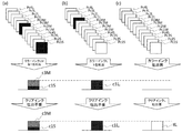
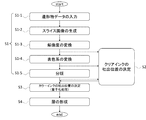
- FIG. 1 shows an example of the structure of the modeling apparatus 100 of this invention. It is a figure which shows an example of the modeled object 50 modeled by the modeling apparatus 100. It is a figure which shows an example of the structure of the head part 110. It is a figure which shows an example of the processing flow by a control unit 140. It is a figure explaining the 1st specific example of the ejection position determination method in the clear ink ejection position determination means 143. It is a figure explaining the 2nd specific example of the ejection position determination method in the clear ink ejection position determination means 143. It is a figure explaining the 3rd specific example of the ejection position determination method in the clear ink ejection position determination means 143.
- FIG. 1 shows an example of the configuration of the modeling apparatus 100 of the present invention.
- the modeling device 100 is a modeling device (3D printer) that models a three-dimensional modeled object 50 by a layered manufacturing method.
- the additive manufacturing method referred to here is data indicating the three-dimensional shape and surface color of the modeled object 50 (hereinafter referred to as "modeled object data") in a predetermined lamination direction with the thickness of the ink layer.
- modeled object data data indicating the three-dimensional shape and surface color of the modeled object 50 (hereinafter referred to as "modeled object data”) in a predetermined lamination direction with the thickness of the ink layer.
- This is a method of modeling a modeled object 50 by slicing and sequentially forming and laminating each layer as an ink layer based on the slice image of each layer obtained thereby.
- FIG. 2 is a diagram showing an example of a modeled object 50 modeled by the modeling apparatus 100, and shows a configuration of an XY cross section which is a cross section of the modeled object 50 orthogonal to the stacking direction (Z direction). ..
- the ZZ cross section and the ZZ cross section of the modeled object 50 perpendicular to the Y direction and the X direction have the same configuration.
- the modeled object 50 has at least an internal region 51 and a colored region 52.
- the modeling apparatus 100 forms the modeled object 50 by sequentially forming and laminating layers of ink having such a cross-sectional structure.
- the internal area 51 is an area that constitutes the inside of the modeled object 50. Further, in the present embodiment, the internal region 51 is formed of white ink to provide a region having the function of a light reflection region.
- the light reflection region is a light reflective region for reflecting light incident from the outside of the modeled object 50 via the colored region 52 or the like.
- the light reflection region may be formed as another region formed around the internal region 51. In that case, the internal region 51 may be formed by using an ink other than the white ink.
- the colored region 52 is an region having a predetermined thickness colored by the color ink.
- the modeling apparatus 100 ejects color inks of each color from each inkjet head of the head portion 110 and lands them around the internal region 51 to form a colored region 52 around the internal region 51 in each layer. At this time, the presence or absence of ejection of color ink of each color to each ejection position constituting the coloring region 52 (each position where the ink ejected from the inkjet head can be landed, which is specified according to the modeling resolution of the modeling apparatus 100). Various colors can be expressed in the colored region 52 by appropriately determining.
- the layer is flattened and the amount of the clear ink used is suppressed.
- regions other than the internal region 51 and the colored region 52 may be further formed according to the quality and the like required for the modeled object 50.
- a transparent region may be formed by ejecting clear ink between the internal region 51 and the colored region 52.
- the internal clear region for example, it is possible to prevent the ink from being mixed between the internal region 51 and the colored region 52.
- a transparent region may be formed by ejecting clear ink around the colored region 52.
- the outer clear region for example, the outer surface of the modeled object 50 can be protected.
- the modeling device 100 may model the modeled object 50 and, if necessary, form a support layer 60 around it.
- the support layer 60 is, for example, a laminated structure that supports the modeled object by surrounding the outer circumference of the modeled object 50 being modeled, and is around when the modeled object 50 alone cannot maintain a stable posture. By forming in, it is possible to stabilize the posture of the modeled object 50 during modeling.
- the support layer 60 is formed, it is formed together with the modeled object 50 using a known material for the support layer that can be easily removed, and is removed after the modeling of the modeled object 50 is completed.
- the modeling device 100 includes a head unit 110, a modeling table 120, a scanning drive unit 130, and a control unit 140.
- the modeling device 100 does not necessarily have to be physically integrally configured.
- one or a plurality of functional units are cut out as separate devices, and information is transmitted and received integrally by wire communication or wireless communication. You may adopt the configuration which makes it function.
- the modeling apparatus 100 may have the same or the same configuration as the known modeling apparatus. Specifically, except for the points described below, the modeling apparatus 100 is the same as or similar to a known modeling apparatus that performs modeling by ejecting droplets that are the material of the modeled object 50 using an inkjet head. It may have features. In addition to the configurations shown in the figure, the modeling apparatus 100 may further include various configurations necessary for modeling the modeled object 50, for example.
- the head portion 110 is a portion that discharges the material of the modeled object 50 (material for the modeled object).
- the material of the modeled object 50 is specifically an ink, and more specifically, for example, an ink that cures according to a predetermined condition.
- the head unit 110 includes a plurality of inkjet heads 111, and ejects predetermined ink from each inkjet head to each ejection position constituting an ink layer in accordance with control by a control unit 140 described later. Each discharge position is determined according to the modeling resolution of the modeling device 100. Then, the ink landed at each ejection position is cured according to a predetermined condition to form an ink layer.
- an ultraviolet curable ink UV ink
- the head portion 110 discharges the ink used as the support material which is the material of the support layer 60, if necessary. As a result, the head portion 110 forms a support layer 60 around the modeled object 50.
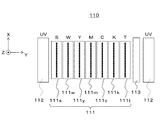
- FIG. 3 shows an example of the configuration of the head portion 110.
- the head portion 110 has a plurality of inkjet heads 111, a plurality of ultraviolet light sources 112, and a flattening roller 113.
- a plurality of inkjet heads 111 as shown in the figure, there are an inkjet head 111s, an inkjet head 111w, an inkjet head 111y, an inkjet head 111m, an inkjet head 111c, an inkjet head 111k, and an inkjet head 111t.
- each inkjet head 111 is examples of ejection heads, and are arranged, for example, by aligning their positions in the sub-scanning direction and arranging them in the main scanning direction. Further, each inkjet head has a nozzle row in which a plurality of nozzles are arranged in a predetermined nozzle row direction on a surface facing the modeling table 120. Further, in this example, the nozzle row direction is a direction parallel to the sub-scanning direction.
- the inkjet head 111s is an inkjet head for a support material that ejects ink used as a support material.
- the support material for example, a known material for the support layer can be preferably used.
- the inkjet heads other than the inkjet heads 111s eject ink which is a material of the modeled object 50.
- the ink used as the material of the modeled object 50 is an ink that constitutes a part of the modeled object when the modeled object 50 is completed.
- the inkjet head 111w is an inkjet head for white ink that ejects white (W color) ink.
- the white ink is an example of a light-reflecting ink, and is used, for example, when forming a region having a property of reflecting light (light-reflecting region) in the modeled object 50.
- the internal region 51 which is a region constituting the interior of the modeled object 50, is formed of white ink so that the internal region 51 functions as a light reflection region.
- the inkjet head 111y, the inkjet head 111m, the inkjet head 111c, and the inkjet head 111k are color ink inkjet heads used when modeling the colored region 52 of the modeled object 50. More specifically, the inkjet head 111y ejects yellow (Y color) ink. The inkjet head 111m ejects magenta (M color) ink. The inkjet head 111c ejects cyan (C color) ink. Further, the inkjet head 111k ejects black (K color) ink. Further, in this example, each color of CMYK is an example of a process color used for full-color expression by the subtractive color mixing method.
- the inkjet head 111t is an inkjet head for clear ink that ejects clear ink.
- the clear ink is, for example, a clear color ink that is colorless and transparent (T) with respect to visible light.
- the clear ink is used when modeling the colored region 52 of the modeled object 50 or the like.
- a head for the color ink inkjet head and the clear ink inkjet head, a head (binary head) in which only one type of ejection amount can be set at a normal ejection timing may be adopted, if necessary.
- a head multi-value head that can be set by selecting a plurality of types of discharge amounts (dot size) may be adopted.
- the plurality of ultraviolet light sources 112 are light sources (UV light sources) for curing the ink, and generate ultraviolet rays for curing the ultraviolet curable ink. Further, in this example, each of the plurality of ultraviolet light sources 112 is arranged on one end side and the other end side of the head portion 110 in the main scanning direction so as to sandwich an array of inkjet heads between them.
- a UV LED ultraviolet LED
- the ultraviolet light source 112 for example, a UV LED (ultraviolet LED) or the like can be preferably used. It is also conceivable to use a metal halide lamp, a mercury lamp, or the like as the ultraviolet light source 112.
- the flattening roller 113 is a flattening means for flattening a layer of ink formed by ink ejected from each inkjet head.
- the flattening roller 113 flattens the ink layer by contacting the surface of the ink layer and removing a part of the ink before curing in a predetermined scanning cycle (for example, during the main scanning operation). , Adjust the thickness of the ink layer to a preset thickness.
- the ink layer constituting the modeled object 50 can be appropriately formed. Further, by forming a plurality of layers of ink in layers, the modeled object 50 can be appropriately modeled.
- the modeling table 120 is a trapezoidal member that supports the modeling object 50 being modeled, is arranged at a position facing the inkjet head in the head portion 110, and the modeling object 50 and the support layer 60 being modeled are placed on the upper surface thereof. Placed. Further, in this example, the modeling table 120 has a configuration in which at least the upper surface can be moved in the stacking direction (Z direction in the drawing), and is driven by the scanning drive unit 130 to model the modeled object 50. At least the upper surface is moved as the process progresses.
- the laminating direction is the direction in which the ink layers are laminated in the additive manufacturing method. Further, in this example, the stacking direction is a direction orthogonal to the main scanning direction (Y direction in the drawing) and the sub scanning direction (X direction in the drawing) set in advance in the modeling apparatus 100.
- the scanning drive unit 130 is a drive unit that causes the head unit 110 to perform a scanning operation that moves relative to the modeled object 50 being modeled.
- the fact that the head portion 110 moves relative to the modeled object 50 being modeled means that the head portion 110 moves relative to the modeling table 120.
- having the head portion 110 perform a scanning operation means having the inkjet head included in the head portion 110 perform a scanning operation.
- the scanning drive unit 130 causes the head unit 110 to perform a main scanning operation (Y scanning), a sub-scanning operation (X scanning), and a stacking direction scanning (Z scanning) as scanning operations.
- the main scanning operation is an operation in which the head portion 110 relatively moves in the main scanning direction with respect to the modeled object 50 being modeled and ejects ink.
- the sub-scanning operation is an operation in which the head portion 110 moves relative to the modeled object 50 being modeled in the sub-scanning direction orthogonal to the main scanning direction. Regarding the sub-scanning operation, it can be considered that the head unit 110 moves relative to the modeling table 120 in the sub-scanning direction by a preset feed amount.
- the stacking direction scanning is an operation of moving the head portion 110 in the stacking direction relative to the modeled object 50 being modeled.
- the scanning drive unit 130 adjusts the relative position of the inkjet head with respect to the modeled object 50 being modeled in the stacking direction by causing the head unit 110 to scan in the stacking direction in accordance with the progress of the modeling operation.
- the modeled object 50 can be appropriately modeled by the additive manufacturing method.
- the control unit 140 has a configuration including a processor and the like, generates a slice image, determines an ejection position for landing each ink ejected by each inkjet head, and ejects each ink to each ejection position by each inkjet head. Perform control and so on.
- the control unit 140 includes a slice image generating means 141, a color ink ejection position determining means 142, a clear ink ejection position determining means 143, and a layer forming means 144.
- the processing performed by each of these means can be realized by the processor.
- each process can be realized by a processor that operates based on information such as a program and a memory that stores information such as a program in which the contents of each process are described.
- the function of each means may be realized by individual hardware, or the function of each means may be realized by integrated hardware.
- various processors such as a CPU, GPU, and DSP can be used.
- a semiconductor memory such as SRAM or DRAM
- a magnetic storage device such as a hard disk device, an optical storage device, or the like
- the memory stores instructions that can be read by a computer, and when the instructions are executed by the processor, processing of each means of the control unit 140 is realized.
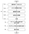
- the slice image generating means 141 Prior to executing the forming operation of the modeled object 50, the slice image generating means 141 generates a plurality of slice images showing the cross-sectional shape and color scheme of each layer of the modeled object 50 at different positions in a predetermined stacking direction. After converting to the resolution and color system according to the modeling device 100, the plates are separated for each color represented by the ink of each color used in the modeling device 100 (S1: slice image generation step).
- the modeled object data indicating the modeled object 50 is input (S1-1).
- the modeled object data is data showing the three-dimensional shape of the modeled object 50, the color of the surface, the orientation at the time of modeling, and the like.
- the surface color may be represented by an arbitrary color system such as an RGB color system or a CMYK color system that does not depend on the modeling device 100.
- the slice image generation means 141 generates a plurality of slice images showing the cross-sectional shape and color scheme of each layer of the modeled object 50 at different positions in the predetermined stacking direction based on the modeled object data (S1-). 2). Specifically, the modeled object data is sliced in the stacking direction with the thickness of the ink layer, and the cross-sectional shape and surface color of each sliced portion are extracted to give the surface color a predetermined thickness. A slice image showing the cross-sectional shape of the internal region 51 and the colored region 52, the color scheme of the colored region 52, and the like is generated by processing such as providing the region 52 around the internal region 51. Each slice image corresponds to each of a plurality of layers of ink formed during the modeling of the modeled object.
- the slice image generating means 141 converts it to the modeling resolution of the modeling device 100 (S1-3).
- the slice image generating means 141 converts the color into a color that matches the color ink of each color used in the modeling apparatus 100. Do (S1-4).
- color conversion to the Lab color system is performed based on the input profile prepared in advance. ..
- the input profile referred to here is, for example, an ICC profile that associates the colors used in the modeled object data with the color space of the Lab color system.
- the color represented in the model data in the RGB color system or the CMYK color system is converted into the color expressed in the Lab color system.
- the slice image generation means 141 is used in the modeling device 100 by using the device profile prepared in advance according to the characteristics of the modeling device 100 (depending on the modeling device 100). ) Perform color conversion according to the color of the color ink.
- the device profile referred to here is, for example, an ICC profile that associates the color space of the Lab color system with the color of the color ink used in the modeling apparatus 100. Using this, the color expressed in the Lab color system is converted into the color of the color ink used in the modeling apparatus 100 (for example, the color of the CMYK color system).
- color conversion when color conversion is performed by such a simple method, it may be difficult to properly express a desired color in the modeled object 50.
- the color gamut (gamut) that can be expressed by a combination of inks of the same color is usually smaller than that when printing a two-dimensional image. Therefore, if color conversion is performed by a simple method without using an ICC profile or the like, color crushing or the like is likely to occur. Therefore, by performing color conversion using a device profile or the like that matches the ink to be used, color conversion can be appropriately performed with higher accuracy.
- the slice image generation means 141 separates the slice image of each layer after performing these processes for each color represented by the ink of each color (S1-5).
- the separation plate corresponds to the ink of each color of C, M, Y, and K4. Generate a sheet of separation slice image. Further, since at least the internal region 51 is formed in white, a separation slice image corresponding to the white ink is generated. Further, when the support layer 60 is formed, a separation slice image corresponding to the ink used as the support material is generated.
- the color ink ejection position determining means 142 determines whether or not each of the plurality of colors of ink for coloring is ejected to each ejection position constituting the ink layer by quantization processing based on the slice image corresponding to the ink layer.
- S2 Color ink ejection position determination step. Specifically, the quantization process is executed on each of the divided slice images corresponding to the inks of each of the separated colors for each ink layer constituting the modeled object 50.
- the quantization process here means that for each pixel constituting the separation slice image, the gradation of light and shade of the color expressed in multiple gradations is reduced by using, for example, the error diffusion method or the dither method. It is a process to convert to.
- the less gradation referred to here is when the inkjet head for color ink provided in the head unit 110 is a head (binary head) in which only one type of ejection amount can be set at a normal ejection timing. Is two gradations corresponding to with and without ejection. In this case, the separation slice image in which each pixel is expressed in multiple gradations is converted into a separation slice image in which each pixel is expressed in two gradations.
- the color ink inkjet head included in the head unit 110 is a head (multi-valued head) in which a plurality of types of ejection amounts (dot sizes) can be selected and set, for example, large, medium, and small dots
- the smaller gradations are four gradations corresponding to with ejection (large dot size), with ejection (medium dot size), with ejection (small dot size), and without ejection. Therefore, in this case, a separation slice image in which each pixel is represented by multiple gradations, for example, each pixel has two gradations (that is, for each of large dot size, medium dot size, and small dot size). Convert to 3 separation slice images represented by (with and without dots).
- the order shown in the processing flow of the slice image generation means 141 in FIG. 4 is not limited to this, and the included processing contents may be appropriately changed within an executable range.
- the clear ink ejection position determining means 143 is a clear ink that is transparent ink to each ejection position based on the presence or absence of ejection of each color ink for coloring at each ejection position determined by the color ink ejection position determining means 142. (S3: Clear ink ejection position determination step).
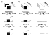
- FIGS. 5 (a) and 5 (b) A first specific example of a method for determining the necessity of discharging clear ink will be described with reference to FIG.
- Pc3 and Pc4 are extracted, and the presence or absence of ejection of color ink of each color to the ejection position corresponding to the pixel position can be identified by coloring the pixels Pc1, Pc2, Pc3, Pc4 with black or white. Specifically, white indicates that there is no ejection of color ink to the corresponding ejection position, and black indicates that there is ejection.
- the maximum number of color inks ejected to one ejection position is one, it is cleared at the position where any color ink (here, color ink c1) is ejected as illustrated in FIG. 5 (a).
- the clear ink t is adjusted so that the position where the color ink is ejected and the thickness of the layer are matched. By determining that the ink is ejected, the thickness of the ink layer can be made uniform.
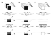
- FIGS. 6 (a), 6 (b), and (c) are divided into four plates corresponding to each of the four color inks c1, c2, c3, and c4. Pixels Pc1, Pc2, Pc3, Pc4 at the same position in the separated slice image are extracted, and the presence or absence of ejection of color ink of each color to the ejection position corresponding to the pixel position is determined by the pixels Pc1, Pc2, Pc3, Pc4. It is made identifiable by the black or white coloring of.
- the maximum number of color inks ejected to one ejection position is one, but in the CMYK color system, for example, two colors are ejected to one ejection position depending on the color to be expressed. In some cases.
- the clear ink inkjet head is a binary head
- the clear ink is cleared at the ejection position where the two color inks (here, the color inks c1 and c3) are ejected as illustrated in FIG. 6A.
- the thickness of the layer can be matched with the ejection position where the two color inks are ejected.
- the thickness of the layer is insufficient with respect to the ejection position where the color ink of.
- the ink layer is excessively ejected to other ejection positions.
- the clear ink inkjet head is a binary head by determining the clear ink ejection position by the method illustrated in FIG.
- FIG. 7 (a), (b), and (c) correspond to the four color inks c1, c2, c3, and c4, respectively, as in FIGS. 6 (a), (b), and (c).
- Pixels Pc1, Pc2, Pc3, and Pc4 at the same position in the separation slice image divided into sheets are extracted, and the presence or absence of ejection of color ink of each color to the ejection position corresponding to the pixel position is determined by the pixels Pc1, Pc2.
- Pc3, Pc4 can be identified by coloring black or white.
- FIG. 7 shows the case where the clear ink is used.
- the inkjet head is a multi-value head.
- the clear ink is not ejected to the ejection position where the two color inks (color inks c1 and c3 in this case) are ejected, and is illustrated in FIG. 7 (b).
- FIG. 7 (a) the clear ink is not ejected to the ejection position where the two color inks (color inks c1 and c3 in this case) are ejected, and is illustrated in FIG. 7 (b).
- the same amount of clear ink tS as the color ink inkjet head is ejected to the ejection position where only one color ink (color ink c1 in this case) is ejected.
- the thickness of the ink layer can be made uniform.
- 8 (a), (b), (c) and 9 (a), (b), (c) show, for example, when both the color ink inkjet head and the clear ink inkjet head are multi-valued heads.
- ink can be ejected with three types (for example, 1x, 2x, 3x) of ink ejection amount (dot size) for each inkjet head, each of the four color inks c1, c2, c3, and c4 Pel Pc1S (dot size S of color ink c1 (1x dot size, the same applies hereinafter)) and Pc2S (color ink) at the same position in the separation slice image divided into a total of 12 sheets corresponding to 3 types of dot sizes.
- Pc2 dot size S Pc3S (color ink c3 dot size S), Pc4S (color ink c4 dot size S), Pc1M (color ink c1 dot size M (double dot size, the same applies hereinafter)), Pc2M (dot size M of color ink c2), Pc3M (dot size M of color ink c3), Pc4M (dot size M of color ink c4), Pc1L (dot size L of color ink c1 (three times the dot size, below) (Same as above)), Pc2L (dot size L of color ink c2), Pc3L (dot size L of color ink c3), and Pc4L (dot size L of color ink c4) are extracted and transferred to the ejection position corresponding to the pixel.
- the presence or absence of ejection of color ink of each color and each dot size is indicated by black or white in two gradations of pixels Pc1S, Pc2S, Pc3S, Pc4S, Pc1M, Pc2M, Pc3M, Pc4M, Pc1L, Pc2L, Pc3L, and Pc4L. It is identifiable based on the coloring.
- the dot size of each color ink ejected to the ejection position determined by the color ink ejection position determining means 142 is determined so that the sum of the sum of the values of and the dot size value of the clear ink discharged to the discharge position is as close as possible to a predetermined reference value. Thereby, the thickness of the formed ink layer can be made uniform.
- FIG. 8 is an example when the predetermined reference value is 3.
- the dot sizes S, M, and L are represented by, for example, numerical values 1, 2, and 3, in the example of FIG. 8A, the color ink c1 having a dot size of 1 and the color ink c3 having a dot size of 2 are ejected.
- the total dot size is 3 because it is ejected to the position. Therefore, since the dot size has reached a predetermined reference value only with the color ink, it is determined that the clear ink is not ejected.
- the total dot size is 3. Therefore, since the dot size has reached a predetermined reference value only with the color ink, it is determined that the clear ink is not ejected.
- the total dot size is 0. Therefore, in this case, it is determined that the clear ink having a dot size of 3 is ejected.
- FIG. 9 is an example when the predetermined reference value is 6.
- the dot sizes S, M, and L are represented by numerical values 1, 2, and 3, in the example of FIG. 9A, the color ink c1 having a dot size of 3 and the color ink c3 having a dot size of 3 are ejected positions.
- the total dot size is 6 because it is discharged to. Therefore, since the dot size has reached a predetermined reference value only with the color ink, it is determined that the clear ink is not ejected.
- the total dot size is 3. Therefore, in this case, it is determined that the clear ink having a dot size of 3 is ejected.
- the total dot size is 0. Therefore, in this case, it is desirable to eject clear ink having a dot size of 6, but since the maximum dot size that can be ejected by the clear ink inkjet head here is 3, the dot size is 6 with respect to the ejection position.
- the thickness of the layer is insufficient. However, even if the thickness is insufficient for some of the ejection positions in this way, for example, when the flattening roller 113 flattens the ink layer at a predetermined scanning cycle, the ink layer is excessively ejected to other ejection positions.
- the dot size of the clear ink may be determined to be 3. If the clear ink inkjet head included in the head unit 110 can adopt the multipath method, it is a technique to eject clear ink having a dot size of 3 at the same ejection position twice, for example, on the outward route and the return route. It is possible. That is, according to this method, clear ink having a dot size of 6 can be ejected to make the thickness of the ink layer uniform.
- the necessity of ejecting clear ink to each ejection position determined as described above is expressed, for example, in two gradations (that is, with ejection and without ejection) for each pixel.
- a slice image for clear ink is generated for each layer.
- the clear ink inkjet head is a multi-value head, a slice image for clear ink is generated for each dot size.
- the layer forming means 144 ejects each of the separation slice images of each color after the quantization process generated by the color ink ejection position determining means 142 and the clear ink slice images generated by the clear ink ejection position determining means 143.
- Information on the presence / absence of ejection of coloring ink to the position and the necessity of ejection of clear ink is read, and the head unit 110 and the scanning drive unit 130 are controlled according to the information to provide the color ink head and the clear ink head for each color.
- S4 Layer formation step
- FIG. 10 shows a processing flow of each means included in the control unit 140 of the present embodiment. Since the content of the slice image generation step (S1) is the same as that of the previous embodiment, the description thereof will be omitted.
- the color ink ejection position determining means 142 of the present embodiment ejects each of a plurality of colors of ink for coloring to each ejection position constituting the ink layer by a quantization process based on a slice image corresponding to the ink layer.
- S3 Color ink ejection position determination step
- the less gradation referred to here is two gradations corresponding to with and without ink ejection.
- the separation slice image in which each pixel is expressed in multiple gradations is converted into a separation slice image in which each pixel is expressed in two gradations.
- the clear ink ejection position determining means 143 Prior to the execution of the quantization process (S3) by the color ink ejection position determining means 142, the clear ink ejection position determining means 143 has the ejection position corresponding to the pixel for each pixel in the colored region of the slice image based on the shading of the pixel. It is determined whether or not the clear ink, which is a transparent ink, needs to be ejected to the ink (S2: Clear ink ejection position determination step).
- this method of determining the ejection position is based on the shading of pixels in the slice image before the execution of the quantization processing, and estimates the presence or absence of color ink ejection to the corresponding ejection position after the quantization processing. This is a method for determining the necessity of ejecting clear ink.
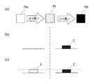
- FIG. 11A shows a pixel Pw having the lightest density, a pixel Pt having a density that serves as a threshold for the necessity of ejecting clear ink, and a pixel Pb having the darkest density.
- FIG. 11B shows the presence or absence of ejection of the color ink C at the ejection position estimated after the quantization process, and corresponds to the case where the density is lighter than that of the pixel Pt. It is estimated that the color ink C is not ejected at the ejection position, and when the pixel is darker than the pixel Pt, the color ink C is estimated to be ejected at the corresponding ejection position.
- the clear ink T is ejected to the ejection position estimated that the color ink C is not ejected, and the clear ink T is ejected to the ejection position estimated to be ejected. Decide whether or not to discharge the ink.
- the resolution of the slice image is converted after determining the shading of the pixel, it is necessary to separately associate the pixel with the ejection position. Therefore, the resolution of the slice image to be determined for the shading of the pixel is determined by the modeling apparatus 100. It is desirable that the pixels of the slice image and the ejection position have a one-to-one correspondence after the execution of the process of converting to the modeling resolution (S1-3).
- the slice image to be determined as the shade of the pixel is a process of converting a color independent of the modeling apparatus 100 into a color matching the color ink of each color used in the modeling apparatus 100 before the quantization process (S1). It may be the one before the execution of -4), the one after the execution, or the one after the execution of the plate separation process (S1-5).
- each pixel can be determined under the following scale, for example.
- the slice image to be judged as the shading of the pixel is the one before the execution of the plate separation processing and the color of the pixel is expressed in the RGB color system, for example, the R value of the pixel, G.
- the sum of the values of and B is equal to or greater than a predetermined threshold value, it may be determined that the clear ink needs to be ejected by presuming that the color ink is not ejected to the corresponding ejection position.
- the image is converted into a grayscale image by an arbitrary method and the grayscale value of the pixel is equal to or higher than a predetermined threshold value, it is estimated that the color ink is not ejected to the corresponding ejection position and the clear ink needs to be ejected. Then you may decide. Further, for example, it is determined that the RGB value of the pixel is converted into the Lab value, and when the L value indicating the brightness is equal to or higher than a predetermined threshold value, it is estimated that the color ink is not ejected to the corresponding ejection position and the clear ink needs to be ejected. You may. Even when the pixel color is represented by a color system other than the RGB color system, it is possible to determine the necessity of ejecting clear ink in the same way as in the case of the RGB color system described above. ..
- the slice image for which the pixel shading is to be determined is the separation slice image after the execution of the separation processing, and the separation slice image is generated for each ink color of C, M, Y, and K.
- the separation slice image is generated for each ink color of C, M, Y, and K.
- the sum of the C value, the M value, the Y value, and the K value in the same pixel is smaller than a predetermined threshold value, it is estimated that the color ink is not ejected to the corresponding ejection position, and the clear ink is used. May be determined to require the discharge of. Even when the color combinations and the number of color types of the separated slice images are different, it is possible to determine the necessity of ejecting the clear ink in the same way as in the case of the above-mentioned CMYK color system.
- a method of determining whether or not the clear ink needs to be ejected to the corresponding ejection position is illustrated only from the pixel value of the target pixel, but for example, the slice image is subjected to some kind of filter (for example, a smoothing filter). Even if the pixel value of the pixel is corrected in consideration of the pixel value around the pixel and the necessity of ejecting the clear ink to the corresponding ejection position is determined based on the corrected pixel value. good.
- the necessity of ejecting clear ink to each ejection position determined as described above is expressed, for example, in two gradations (that is, with ejection and without ejection) for each pixel.
- a slice image for clear ink is generated for each layer.
- the clear ink inkjet head included in the head unit 110 is a head (multi-valued head) in which a plurality of types of ejection amounts (dot sizes) can be selected and set, the clear ink can be used according to the pixel density. It is possible to set the discharge amount step by step.
- the coloring ink colors used in the modeling apparatus 100 are four colors of CMYK
- the coloring ink is not ejected at each ejection position, one color is ejected, and two colors are ejected.
- two threshold values are set for the shading of the pixels in the slice image before the execution of the quantization process, and when the threshold value is thinner than the lighter threshold value, the coloring ink is not ejected at the ejection position. If it is darker than the lighter threshold value and lighter than the darker threshold value, one color of coloring ink is ejected, and if it is darker than the darker threshold value, two colors of coloring ink are ejected. Can be done.
- FIG. 12A shows a pixel Pw having the lightest density, a pixel Pt1 having a density that is the first threshold value for the necessity of ejecting clear ink, and a density that is a second threshold value that is darker than the first threshold value.
- Pixel Pt2 and pixel Pb having the darkest density are shown.
- FIG. 12B shows the presence or absence of ejection of the first color ink C1 and the second color ink C2 at the ejection position estimated after the quantization treatment.
- a large amount of clear ink Tm is ejected to the ejection position estimated that none of the color inks is ejected, and only the first color ink C1 is ejected.
- the necessity of ejection is determined such that a small amount of clear ink Ts is ejected to the estimated ejection position and the clear ink is not ejected to the ejection position where both color inks are estimated to be ejected.
- the clear ink ejection position determining means 143 determines whether or not the clear ink is ejected to each ejection position determined as described above, for example, with ejection (large dot size) and with ejection (small dot size). For each, two slice images for clear ink are generated for each layer, in which each pixel is represented by two gradations corresponding to with and without ejection.
- the clear ink ejection amount can be stepped even if the clear ink inkjet head provided in the head portion 110 is a head (binary head) in which only one type of ejection amount can be set at a normal ejection timing. If the multi-pass method can be adopted, it is technically possible to eject the clear ink to the same ejection position twice, for example, on the outward route and the return route. Therefore, even in this case, it is possible to increase or decrease the discharge amount of the clear ink according to the discharge amount of the color ink by the same method as in the case of adopting the multi-value head.
- the layer forming means 144 ejects each of the separation slice images of each color after the quantization process generated by the color ink ejection position determining means 142 and the clear ink slice images generated by the clear ink ejection position determining means 143.
- Information on the presence / absence of ejection of coloring ink to the position and the necessity of ejection of clear ink is read, and the head unit 110 and the scanning drive unit 130 are controlled according to the information to provide the color ink head and the clear ink head for each color.
- S4 Layer formation step
- the modeling apparatus 100 of the present invention described above determines the necessity of ejecting clear ink for each ejection position and ejects clear ink according to the determination, the amount of clear ink used at the time of forming each layer can be saved. At the same time, the amount of ink scraped off during flattening can be reduced, so that deterioration of the quality of the surface of the modeled object can be suppressed.
- the present invention is not limited to each of the above embodiments.
- Each of the above embodiments is an example, and any one having substantially the same configuration as the technical idea described in the claims of the present invention and exhibiting the same effect and effect is the present invention. It is included in the technical scope of the invention. That is, each of the above embodiments can be appropriately changed within the scope of the technical idea expressed in the present invention, and the form to which such a change or improvement is added is also included in the technical scope of the present invention.
Landscapes
- Chemical & Material Sciences (AREA)
- Engineering & Computer Science (AREA)
- Materials Engineering (AREA)
- Manufacturing & Machinery (AREA)
- Physics & Mathematics (AREA)
- Mechanical Engineering (AREA)
- Optics & Photonics (AREA)
- Ink Jet (AREA)
Abstract
各層の形成時におけるクリアインクの使用量の節約及び平坦化時における造形物表面の品質の悪化を抑制可能な造形装置を提供する。 造形物の各層の断面形状及び配色を示す複数のスライス画像に基づき各層を形成し積層することで造形物を造形する造形装置において、層に対応するスライス画像に基づき層を構成する各吐出位置への着色用の複数色のインクそれぞれの吐出の有無を決定するカラーインク吐出位置決定手段と、カラーインク吐出位置決定手段において決定された各吐出位置への着色用の各色のインクの吐出の有無に基づき、各吐出位置へのクリアインクの吐出の要否を決定するクリアインク吐出位置決定手段と、カラーインク用ヘッドとクリアインク用ヘッドにカラーインク吐出位置決定手段及びクリアインク吐出位置決定手段における決定に従い各吐出位置に各色のインク及びクリアインクを吐出させる層形成手段と、を備える。
Description
本発明は、造形装置及び造形方法に関する。
従来、インクジェットヘッドを用いて造形物を造形する造形装置(3Dプリンタ)が知られている(例えば、特許文献1参照。)。このような造形装置においては、例えば、インクジェットヘッドにより形成するインクの層を複数層重ねることにより造形する積層造形法で造形物を造形する。
積層造形法で造形物の造形を行う場合、造形不良が生じないよう、1層の積層厚をできるだけ均一にする必要がある。
1層の積層厚を均一にする方法として、例えば、カラーインクの吐出後、吐出されたカラーインクの量にかかわらず、期待する積層厚以上になるよう、多め且つ一定量のクリアインクを吐出し、期待する積層厚を超えるインクを平坦化ローラで掻き取る方法が挙げられる。
しかし、この方法による場合、平坦化ローラにより掻き取られたインクは廃棄することになるため、掻き取られる量が多ければ、その分コストに無駄が生じる。また、掻き取られるインクの量が多いほど造形物表面の品質が悪化する。
そこで本発明は、上記の課題を解決可能な造形装置及び造形方法を提供することを目的とする。
本発明の造形装置は、予め定められた積層方向におけるそれぞれ異なる位置での造形物の各層の断面形状及び配色を示す複数のスライス画像に基づき、各層をインクの層として形成し、積層させることにより造形物を造形する造形装置であって、層に対応するスライス画像に基づき、量子化処理により、層を構成する各吐出位置への着色用の複数色のインクそれぞれの吐出の有無を決定するカラーインク吐出位置決定手段と、カラーインク吐出位置決定手段において決定された各吐出位置への着色用の各色のインクの吐出の有無に基づき、各吐出位置への、透明なインクであるクリアインクの吐出の要否を決定するクリアインク吐出位置決定手段と、複数色のインクのそれぞれを吐出可能なカラーインク用ヘッドと、クリアインクを吐出可能なクリアインク用ヘッドと、カラーインク用ヘッドとクリアインク用ヘッドに、カラーインク吐出位置決定手段及びクリアインク吐出位置決定手段における決定に従い、各吐出位置に各色のインク及びクリアインクを吐出させることにより層を形成する層形成手段と、を備える。
カラーインク吐出位置決定手段は、吐出するインクのドットサイズを更に決定し、クリアインク吐出位置決定手段は、カラーインク吐出位置決定手段において決定された各吐出位置への着色用の複数色のインクそれぞれの吐出の有無及びドットサイズに基づき、各吐出位置へのクリアインクの吐出の有無及びドットサイズを決定し、カラーインク用ヘッドとクリアインク用ヘッドは、それぞれ、複数種類のドットサイズのインクを吐出可能であり、層形成手段は、カラーインク用ヘッドとクリアインク用ヘッドに、各吐出位置へ、カラーインク吐出位置決定手段及びクリアインク吐出位置決定手段における決定に従ったドットサイズの各色のインク及びクリアインクを吐出させてもよい。
これにより、各吐出位置について、吐出されたカラーインクのドットサイズに応じたドットサイズのクリアインクを充填することができる。
ドットサイズを、ドットのサイズが大きいほど値が大きくなる数値で表現したとき、クリアインク吐出位置決定手段は、カラーインク吐出位置決定手段において決定された、吐出位置に吐出される着色用の各色のインクのドットサイズの値の合計と、吐出位置に吐出されるクリアインクのドットサイズの値との和が、所定の基準値にできるだけ近くなるように、吐出位置に吐出されるクリアインクのドットサイズを決定してもよい。
これにより、形成されるインクの層の厚さの均一化を図ることができる。
本発明の造形方法は、予め定められた積層方向におけるそれぞれ異なる位置での造形物の各層の断面形状及び配色を示す複数のスライス画像に基づき、各層をインクの層として形成し、積層させることにより造形物を造形する造形方法であって、層に対応するスライス画像に基づき、量子化処理により、層を構成する各吐出位置への着色用の複数色のインクそれぞれの吐出の有無を決定するカラーインク吐出位置決定ステップと、カラーインク吐出位置決定ステップにおいて決定された各吐出位置への着色用の各色のインクの吐出の有無に基づき、各吐出位置への、透明なインクであるクリアインクの吐出の要否を決定するクリアインク吐出位置決定ステップと、カラーインク用ヘッドとクリアインク用ヘッドに、カラーインク吐出位置決定ステップ及びクリアインク吐出位置決定ステップにおける決定に従い、各吐出位置に各色のインク及びクリアインクを吐出させることにより層を形成する層形成ステップと、を実行する。
カラーインク吐出位置決定ステップは、吐出するインクのドットサイズを更に決定し、
クリアインク吐出位置決定ステップは、カラーインク吐出位置決定ステップにおいて決定された各吐出位置への着色用の複数色のインクそれぞれの吐出の有無及びドットサイズに基づき、各吐出位置へのクリアインクの吐出の有無及びドットサイズを決定し、カラーインク用ヘッドとクリアインク用ヘッドは、それぞれ、複数種類のドットサイズのインクを吐出可能であり、層形成ステップは、カラーインク用ヘッドとクリアインク用ヘッドに、各吐出位置へ、カラーインク吐出位置決定ステップ及びクリアインク吐出位置決定ステップにおける決定に従ったドットサイズの各色のインク及びクリアインクを吐出させてもよい。
クリアインク吐出位置決定ステップは、カラーインク吐出位置決定ステップにおいて決定された各吐出位置への着色用の複数色のインクそれぞれの吐出の有無及びドットサイズに基づき、各吐出位置へのクリアインクの吐出の有無及びドットサイズを決定し、カラーインク用ヘッドとクリアインク用ヘッドは、それぞれ、複数種類のドットサイズのインクを吐出可能であり、層形成ステップは、カラーインク用ヘッドとクリアインク用ヘッドに、各吐出位置へ、カラーインク吐出位置決定ステップ及びクリアインク吐出位置決定ステップにおける決定に従ったドットサイズの各色のインク及びクリアインクを吐出させてもよい。
これにより、各吐出位置について、吐出されたカラーインクのドットサイズに応じたドットサイズのクリアインクを充填することができる。
ドットサイズを、ドットのサイズが大きいほど値が大きくなる数値で表現したとき、クリアインク吐出位置決定ステップは、カラーインク吐出位置決定ステップにおいて決定された、吐出位置に吐出される着色用の各色のインクのドットサイズの値の合計と、吐出位置に吐出されるクリアインクのドットサイズの値との和が、所定の基準値にできるだけ近くなるように、吐出位置に吐出されるクリアインクのドットサイズを決定してもよい。
これにより、形成されるインクの層の厚さの均一化を図ることができる。
また、本発明の造形装置は、予め定められた積層方向におけるそれぞれ異なる位置での造形物の各層の断面形状及び配色を示す複数のスライス画像に基づき、各層をインクの層として形成し、積層させることにより造形物を造形する造形装置であって、層に対応するスライス画像に基づき、量子化処理により、層を構成する各吐出位置への着色用の複数色のインクそれぞれの吐出の有無を決定するカラーインク吐出位置決定手段と、カラーインク吐出位置決定手段による量子化処理の実行に先立ち、スライス画像の着色領域における各画素について、画素の濃淡に基づき、画素に対応する吐出位置への、透明なインクであるクリアインクの吐出の要否を決定するクリアインク吐出位置決定手段と、複数色のインクのそれぞれを吐出可能なカラーインク用ヘッドと、クリアインクを吐出可能なクリアインク用ヘッドと、カラーインク用ヘッドとクリアインク用ヘッドに、カラーインク吐出位置決定手段及びクリアインク吐出位置決定手段における決定に従い、各吐出位置に各色のインク及びクリアインクを吐出させることにより層を形成する層形成手段と、を備える。
スライス画像は、各画素において、所定の表色系の各色について画素値が多階調で示された画像であってもよい。
また、スライス画像は、複数色のインクの色ごとに分版され、それぞれ各画素において画素値が多階調で示された複数の画像からなるものであってもよい。
分版後のスライス画像に基づき各吐出位置へのクリアインクの吐出の要否を決定することで、分版前のスライス画像に基づき決定する場合と比べ、クリアインクの吐出の要否の決定精度を高めることができる。
クリアインク吐出位置決定手段は、吐出有りの場合には、画素の濃淡に基づきインクのドットサイズを更に決定し、クリアインク用ヘッドは、複数種類のドットサイズのインクを吐出可能であり、層形成手段は、クリアインク用ヘッドに、各吐出位置へ、クリアインク吐出位置決定手段における決定に従ったドットサイズのクリアインクを吐出させてもよい。
これにより、ドットサイズが均一な場合と比べ、より適切な量でクリアインクを充填することができる。
本発明の造形方法は、予め定められた積層方向におけるそれぞれ異なる位置での造形物の各層の断面形状及び配色を示す複数のスライス画像に基づき、各層をインクの層として形成し、積層させることにより造形物を造形する造形方法であって、層に対応するスライス画像に基づき、量子化処理により、層を構成する各吐出位置への着色用の複数色のインクそれぞれの吐出の有無を決定するカラーインク吐出位置決定ステップと、カラーインク吐出位置決定ステップにおける量子化処理の実行に先立ち、スライス画像の着色領域における各画素について、画素の濃淡に基づき、画素に対応する吐出位置への、透明なインクであるクリアインクの吐出の要否を決定するクリアインク吐出位置決定ステップと、カラーインク用ヘッドとクリアインク用ヘッドに、カラーインク吐出位置決定ステップ及びクリアインク吐出位置決定ステップにおける決定に従い、各吐出位置に各色のインク及びクリアインクを吐出させることにより層を形成する層形成ステップと、を実行する。
スライス画像は、各画素において、所定の表色系の各色について画素値が多階調で示された画像であってもよい。
また、スライス画像は、複数色のインクの色ごとに分版され、それぞれ各画素において画素値が多階調で示された複数の画像からなるものであってもよい。
分版後のスライス画像に基づき各吐出位置へのクリアインクの吐出の要否を決定することで、分版前のスライス画像に基づき決定する場合と比べ、クリアインクの吐出の要否の決定精度を高めることができる。
クリアインク吐出位置決定ステップは、吐出有りの場合には、画素の濃淡に基づきインクのドットサイズを更に決定し、クリアインク用ヘッドは、複数種類のドットサイズのインクを吐出可能であり、層形成ステップは、クリアインク用ヘッドに、各吐出位置へ、クリアインク吐出位置決定ステップにおける決定に従ったドットサイズのクリアインクを吐出させてもよい。
これにより、ドットサイズが均一な場合と比べ、より適切な量でクリアインクを充填することができる。
本発明の造形装置及び造形方法は、クリアインクの吐出の要否を吐出位置ごとに判定し、それに従ってクリアインクを吐出するため、各層の形成時におけるクリアインクの使用量を節約することができるとともに、平坦化の際にインクを掻き取る量も減らすことができるため、造形物表面の品質の悪化を抑えることができる。
以下、本発明の実施形態を、図面を参照しつつ説明する。なお、以下の説明及び図面では、同一の機能部には同一の符号を付し、一度説明した機能部については説明を省略するか、必要な範囲で説明する。
図1に、本発明の造形装置100の構成の一例を示す。造形装置100は、積層造形法により立体的な造形物50を造形する造形装置(3Dプリンタ)である。ここでいう積層造形法とは、造形物50の3次元形状や表面の色などを示すデータ(以下「造形物データ」という。)を、予め定められた積層方向にインクの層の厚さでスライスし、これにより得られた各層のスライス画像に基づき、各層をインクの層として順次形成し積層していくことで造形物50を造形する方法である。
図2は、造形装置100により造形される造形物50の一例を示す図であり、積層方向(Z方向)と直交する造形物50の断面であるX-Y断面の構成を示したものである。Y方向やX方向と垂直な造形物50のZ-X断面やZ-Y断面の構成も、同様の構成になる。
造形物50は、内部領域51及び着色領域52を少なくとも有する。造形装置100は、このような断面構成のインクの層を順次形成し積層することにより造形物50を造形する。
内部領域51は、造形物50の内部を構成する領域である。また、本実施形態においては、内部領域51を白色のインクで形成することで、光反射領域の機能を兼ね備えた領域としている。光反射領域とは、着色領域52等を介して造形物50の外側から入射する光を反射するための光反射性の領域のことである。光反射領域は、内部領域51の周囲に形成される別の領域として形成してもよい。その場合は、内部領域51を白色のインク以外のインクを用いて形成してもよい。
着色領域52は、カラーインクにより着色される所定の厚みを持つ領域である。造形装置100は、ヘッド部110の各インクジェットヘッドから各色のカラーインクを吐出し、内部領域51の周囲に着弾させることにより、各層において内部領域51の周囲に着色領域52を形成する。このとき、着色領域52を構成する各吐出位置(造形装置100の造形解像度に応じて特定される、インクジェットヘッドから吐出されるインクを着弾させうる各位置)への各色のカラーインクの吐出の有無を適宜決定することにより、着色領域52において様々な色を表現することができる。
また、表現する色の違いにより、各吐出位置に堆積するカラーインクの量がばらつくと、凹凸のあるインクの層が形成されることになり、このような層を積層することは造形物50の品質や強度の低下につながる。そこで、本発明においては、後述の方法により、カラーインクが吐出されない吐出位置などに重点的にクリアインクを吐出することで、層の平坦化を図るとともに、クリアインクの使用量の抑制を図る。
なお、造形物50に求められる品質等に応じ、内部領域51及び着色領域52以外の領域を更に形成してもよい。例えば、内部領域51と着色領域52との間にクリアインクを吐出することにより透明な領域(内部クリア領域)を形成してもよい。内部クリア領域を形成することにより、例えば、内部領域51と着色領域52との間でインクの混色が生じることを防ぐことができる。また、着色領域52の周囲にクリアインクを吐出することにより透明な領域(外部クリア領域)を形成してもよい。外部クリア領域を形成することにより、例えば、造形物50の外面を保護することができる。
造形装置100は、造形物50を造形するとともに、必要に応じて周囲にサポート層60を形成してもよい。サポート層60とは、例えば、造形中の造形物50の外周を囲むことで造形物を支持する積層構造物であり、造形物50単体では体勢の安定が保てない形状である場合などに周囲に形成することで、造形中の造形物50の体勢の安定化を図ることができる。サポート層60を形成する場合は、除去が容易なサポート層用の公知の材料を用いて造形物50とともに形成し、造形物50の造形完了後に除去する。
造形装置100は、例えば図1に示すように、ヘッド部110、造形台120、走査駆動部130、及び制御部140を有する。ただし、造形装置100は必ずしも物理的に一体的に構成されなくてもよく、例えば、1又は複数の機能部を別の装置として切り出し、有線通信又は無線通信により情報を送受するなどして一体的に機能させる構成を採ってもよい。
また、以下に説明をする点を除き、造形装置100は、公知の造形装置と同一又は同様の構成を有してよい。具体的には、以下に説明をする点を除き、造形装置100は、インクジェットヘッドを用いて造形物50の材料となる液滴を吐出することで造形を行う公知の造形装置と同一又は同様の特徴を有してよい。また、造形装置100は、図示した構成以外にも、例えば、造形物50の造形等に必要な各種構成を更に備えてもよい。
ヘッド部110は、造形物50の材料(造形物用材料)を吐出する部分である。造形物50の材料は、具体的にはインクであり、より具体的には例えば、所定の条件に応じて硬化するインクである。ヘッド部110は、複数のインクジェットヘッド111を備え、それぞれのインクジェットヘッドから、後述する制御部140による制御に従い、インクの層を構成する各吐出位置に所定のインクを吐出する。各吐出位置は、造形装置100の造形解像度に応じて決定される。そして、各吐出位置に着弾したインクを所定の条件に応じて硬化させることにより、インクの層が形成される。本例では、所定の条件に応じて硬化するインクとして、紫外線の照射により液体状態から硬化する紫外線硬化型インク(UVインク)を用いる。
また、ヘッド部110は、造形物50の材料として用いるインクに加え、必要に応じサポート層60の材料であるサポート材として用いるインクを吐出する。これにより、ヘッド部110は、造形物50の周囲にサポート層60を形成する。
ヘッド部110の構成について、更に詳しく説明をする。図3は、ヘッド部110の構成の一例を示す。本例において、ヘッド部110は、複数のインクジェットヘッド111、複数の紫外線光源112、及び平坦化ローラ113を有する。また、複数のインクジェットヘッド111として、図中に示すように、インクジェットヘッド111s、インクジェットヘッド111w、インクジェットヘッド111y、インクジェットヘッド111m、インクジェットヘッド111c、インクジェットヘッド111k、及びインクジェットヘッド111tを有する。これらの複数のインクジェットヘッド111は、吐出ヘッドの一例であり、例えば、副走査方向における位置を揃えて、主走査方向へ並べて配設される。また、それぞれのインクジェットヘッドは、造形台120と対向する面に、所定のノズル列方向へ複数のノズルが並ぶノズル列を有する。また、本例において、ノズル列方向は、副走査方向と平行な方向である。
インクジェットヘッド111sは、サポート材として用いるインクを吐出するサポート材用インクジェットヘッドである。サポート材としては、例えば、サポート層用の公知の材料を好適に用いることができる。また、ヘッド部110における複数のインクジェットヘッド111のうち、インクジェットヘッド111s以外のインクジェットヘッドは、造形物50の材料となるインクを吐出する。造形物50の材料となるインクとは、造形物50の完成時に造形物の一部を構成するインクのことである。
インクジェットヘッド111wは、白色(W色)のインクを吐出する白色インク用インクジェットヘッドである。白色のインクは、光反射性のインクの一例であり、例えば造形物50において光を反射する性質の領域(光反射領域)を形成する際に用いられる。図2に示す例では、造形物50の内部を構成する領域である内部領域51を白色のインクで形成することで、内部領域51を光反射領域として機能させる。
インクジェットヘッド111y、インクジェットヘッド111m、インクジェットヘッド111c、インクジェットヘッド111kは、造形物50の着色領域52の造形時に用いられるカラーインク用インクジェットヘッドである。より具体的には、インクジェットヘッド111yは、イエロー色(Y色)のインクを吐出する。インクジェットヘッド111mは、マゼンタ色(M色)のインクを吐出する。インクジェットヘッド111cは、シアン色(C色)のインクを吐出する。また、インクジェットヘッド111kは、ブラック色(K色)のインクを吐出する。また、本例において、CMYKの各色は、減法混色法によるフルカラー表現に用いるプロセスカラーの一例である。
インクジェットヘッド111tは、クリアインクを吐出するクリアインク用インクジェットヘッドである。クリアインクとは、例えば、可視光に対して無色で透明(T)なクリア色のインクのことである。クリアインクは、造形物50の着色領域52の造形時などに用いられる。
なお、カラーインク用インクジェットヘッドとクリアインク用インクジェットヘッドには、必要に応じ、通常の吐出のタイミングで1種類の吐出量のみが設定可能なヘッド(2値ヘッド)を採用してもよいし、複数種類の吐出量(ドットサイズ)を選択して設定可能なヘッド(多値ヘッド)を採用してもよい。
複数の紫外線光源112は、インクを硬化させるための光源(UV光源)であり、紫外線硬化型インクを硬化させる紫外線を発生する。また、本例において、複数の紫外線光源112のそれぞれは、間にインクジェットヘッドの並びを挟むように、ヘッド部110における主走査方向の一端側及び他端側のそれぞれに配設される。紫外線光源112としては、例えば、UVLED(紫外LED)等を好適に用いることができる。また、紫外線光源112として、メタルハライドランプや水銀ランプ等を用いることも考えられる。
平坦化ローラ113は、各インクジェットヘッドから吐出されたインクにより形成されたインクの層を平坦化するための平坦化手段である。平坦化ローラ113は、所定の走査周期(例えば主走査動作時)において、インクの層の表面と接触して、硬化前のインクの一部を除去することにより、インクの層を平坦化するとともに、インクの層の厚さを予め設定された厚さに調整する。
以上のような構成のヘッド部110を用いることにより、造形物50を構成するインクの層を適切に形成できる。また、複数のインクの層を重ねて形成することにより、造形物50を適切に造形できる。
造形台120は、造形中の造形物50を支持する台状部材であり、ヘッド部110におけるインクジェットヘッドと対向する位置に配設され、造形中の造形物50及びサポート層60がその上面に載置される。また、本例において、造形台120は、少なくとも上面が積層方向(図中のZ方向)へ移動可能な構成を有しており、走査駆動部130に駆動されることにより、造形物50の造形の進行に合わせて、少なくとも上面を移動させる。積層方向とは、積層造形法においてインクの層が積層される方向のことである。また、本例において、積層方向は、造形装置100において予め設定される主走査方向(図中のY方向)及び副走査方向(図中のX方向)と直交する方向である。
走査駆動部130は、造形中の造形物50に対して相対的に移動する走査動作をヘッド部110に行わせる駆動部である。造形中の造形物50に対してヘッド部110が相対的に移動するとは、ヘッド部110が造形台120に対して相対的に移動することである。また、ヘッド部110に走査動作を行わせるとは、ヘッド部110が有するインクジェットヘッドに走査動作を行わせることである。また、本例において、走査駆動部130は、走査動作として、主走査動作(Y走査)、副走査動作(X走査)、及び積層方向走査(Z走査)をヘッド部110に行わせる。
主走査動作とは、造形中の造形物50に対してヘッド部110が相対的に主走査方向へ移動しつつインクを吐出する動作のことである。副走査動作とは、ヘッド部110が、主走査方向と直交する副走査方向へ造形中の造形物50に対して相対的に移動する動作のことである。副走査動作については、ヘッド部110が、予め設定された送り量だけ副走査方向へ造形台120に対して相対的に移動する動作等と考えることもできる。また、積層方向走査とは、造形中の造形物50に対して相対的に積層方向へヘッド部110を移動させる動作のことである。走査駆動部130は、造形の動作の進行に合わせてヘッド部110に積層方向走査を行わせることにより、積層方向において、造形中の造形物50に対するインクジェットヘッドの相対位置を調整する。このように構成することで、積層造形法による造形物50の造形を適切に行うことができる。
制御部140は、プロセッサなどを含む構成であり、スライス画像の生成、各インクジェットヘッドにより吐出された各インクを着弾させる吐出位置の決定、及び各吐出位置への各インクジェットヘッドによる各インクの吐出の制御などを行う。
制御部140は、スライス画像生成手段141、カラーインク吐出位置決定手段142、クリアインク吐出位置決定手段143及び層形成手段144を含む。これらの各手段が行う処理はプロセッサにより実現できる。具体的には、各処理はプログラム等の情報に基づき動作するプロセッサと、各処理の内容が記述されたプログラム等の情報を記憶するメモリにより実現できる。プロセッサは、例えば各手段の機能が個別のハードウェアで実現されてもよいし、各手段の機能が一体のハードウェアで実現されてもよい。プロセッサは、例えばCPU、GPU、DSPなど各種のプロセッサを用いることが可能である。メモリは、例えばSRAMやDRAMなどの半導体メモリ、ハードディスク装置などの磁気記憶装置、光学的記憶装置などを用いることが可能である。メモリはコンピュータにより読み取り可能な命令を格納しており、当該命令がプロセッサにより実行されることで、制御部140の各手段の処理が実現される。
続いて、制御部140に含まれる各手段が担う処理について説明する。処理フローを図4に示す。
スライス画像生成手段141は、造形物50の形成動作の実行に先立ち、予め定められた積層方向におけるそれぞれ異なる位置での造形物50の各層の断面形状及び配色を示す複数のスライス画像を生成し、造形装置100に合わせた解像度及び表色系への変換を行った上で、造形装置100で用いる各色のインクで表現される色ごとに分版する(S1:スライス画像生成ステップ)
具体的には、まず、造形物50を示す造形物データが入力される(S1-1)。造形物データは、造形物50の3次元形状、表面の色、造形時の向きなどを示すデータである。造形物データにおいて、表面の色は、造形装置100に依存しないRGB表色系やCMYK表色系など、任意の表色系により表現されていてよい。
続いて、スライス画像生成手段141は、造形物データに基づき、予め定められた積層方向におけるそれぞれ異なる位置での造形物50の各層の断面形状及び配色を示す複数のスライス画像を生成する(S1-2)。具体的には、造形物データを積層方向にインクの層の厚さでスライスし、スライスされたそれぞれの部分について、断面形状と表面色を抽出し、表面色に所定の厚みを持たせた着色領域52を内部領域51の周囲に設けるなどの処理により、内部領域51及び着色領域52の断面形状、並びに着色領域52の配色などを示すスライス画像を生成する。それぞれのスライス画像は、造形物の造形時に形成する複数のインクの層のそれぞれに対応する。
続いて、スライス画像生成手段141は、スライス画像の解像度が造形装置100の造形解像度と異なる場合、造形装置100の造形解像度に変換する(S1-3)。
また、スライス画像生成手段141は、スライス画像の着色領域52において表現されている色が造形装置100に依存しない色である場合、造形装置100で使用する各色のカラーインクに合わせた色に変換を行う(S1-4)。
具体的には、例えばまず、スライス画像の着色領域52において造形装置100に依存しない形式で表現されている色に対し、予め用意された入力プロファイルに基づき、Lab表色系への色変換を行う。ここでいう入力プロファイルとは、例えば、造形物データにおいて使用されている色とLab表色系の色空間とを対応付けるICCプロファイルである。これを用い、例えばRGB表色系又はCMYK表色系で造形物データにおいて表現されている色を、Lab表色系で表現される色に変換する。
Lab表色系への色変換を行った後、スライス画像生成手段141は、造形装置100の特性に合わせて予め用意されたデバイスプロファイルを用いて、造形装置100で使用する(造形装置100に依存する)カラーインクの色に合わせた色変換を行う。ここでいうデバイスプロファイルとは、例えば、Lab表色系の色空間と造形装置100で使用するカラーインクの色とを対応付けるICCプロファイルである。これを用い、Lab表色系で表現されている色を、造形装置100で使用するカラーインクの色(例えばCMYK表色系の色)に変換する。
なお、単に造形物データに基づいて造形実行用データを生成することを考えた場合、ICCプロファイル等のプロファイルを用いた色変換等を行わずに、より単純な方法で色変換を行うこと等も考えられる。すなわち、例えば、造形物データにおいてRGB表色系で表現されている色について、一定の変換式等に従って形式的にCMYK表色系で表現される色に変換すること等も考えられる。
しかし、このような単純な方法で色変換を行った場合、造形物50において所望の色を適切に表現することが難しくなる場合がある。例えば、立体的な造形物50を造形する場合、2次元の画像を印刷する場合と比べ、通常、同じ色のインクの組み合わせで表現可能な色の範囲(ガマット)が小さくなる。そのため、ICCプロファイル等を用いずに単純な方法で色変換を行うと、色の潰れ等が生じやすくなる。そこで、使用するインクに合わせたデバイスプロファイル等を用いて色変換を行うことで、より高い精度で適切に色変換を行うことができる。
続いて、スライス画像生成手段141は、これらの処理を行った後の各層のスライス画像を、各色のインクで表現される色ごとに分版する(S1-5)。
分版は具体的には、スライス画像の着色領域52の各画素が、例えばCMYK表色系で表現されている場合には、C、M、Y及びKのそれぞれの色のインクに対応する4枚の分版スライス画像を生成する。また、少なくとも内部領域51が白色で形成されるため、白色のインクに対応する分版スライス画像を生成する。更に、サポート層60を形成する場合には、サポート材として用いるインクに対応する分版スライス画像を生成する。
カラーインク吐出位置決定手段142は、インクの層に対応するスライス画像に基づき、量子化処理により、インクの層を構成する各吐出位置への着色用の複数色のインクそれぞれの吐出の有無を決定する(S2:カラーインク吐出位置決定ステップ)。具体的には、造形物50を構成するそれぞれのインクの層について、分版された各色のインクに対応するそれぞれの分版スライス画像に対して量子化処理を実行する。
ここでいう量子化処理とは、分版スライス画像を構成する各画素について、多階調で表現された色の明暗の階調を、例えば誤差拡散法やディザ法を用いて、より少ない階調に変換する処理である。
また、ここでいう、より少ない階調とは、ヘッド部110が備えるカラーインク用インクジェットヘッドが、通常の吐出のタイミングで1種類の吐出量のみが設定可能なヘッド(2値ヘッド)の場合には、吐出有りと吐出無しに対応する2階調である。この場合には、それぞれの画素が多階調で表現された分版スライス画像を、それぞれの画素が2階調で表現された分版スライス画像に変換する。
一方、ヘッド部110が備えるカラーインク用インクジェットヘッドが、複数種類の吐出量(ドットサイズ)を選択して設定可能なヘッド(多値ヘッド)の場合には、例えば、大、中、小のドットサイズを選択できるとすると、より少ない階調とは、吐出有り(ドットサイズ大)、吐出有り(ドットサイズ中)、吐出有り(ドットサイズ小)、吐出無しにそれぞれ対応する4階調である。そのため、この場合にはそれぞれの画素が多階調で表現された分版スライス画像を、例えば、ドットサイズ大、ドットサイズ中、ドットサイズ小のそれぞれについて、それぞれの画素が2階調(すなわち、ドット有りとドット無し)で表現された3枚の分版スライス画像に変換する。
なお、図4のスライス画像生成手段141の処理フローに示す順序はその限りではなく、含まれる処理内容を実行可能な範囲で適宜変更して構わない。
クリアインク吐出位置決定手段143は、カラーインク吐出位置決定手段142において決定された各吐出位置における着色用の各色のインクの吐出の有無に基づき、各吐出位置への、透明なインクであるクリアインクの吐出の要否を決定する(S3:クリアインク吐出位置決定ステップ)。
クリアインクの吐出要否の決定方法の第1の具体例を、図5を参照しつつ説明する。図5(a),(b)はいずれも、4色のカラーインクc1、c2、c3、c4のそれぞれに対応する4枚に分版された分版スライス画像における同じ位置の画素Pc1、Pc2、Pc3、Pc4を抽出し、その画素位置に対応する吐出位置への各色のカラーインクの吐出の有無を、画素Pc1、Pc2、Pc3、Pc4の黒又は白の着色により識別可能としたものであり、具体的には白は対応する吐出位置へのカラーインクの吐出が無いことを示し、黒は吐出が有ることを示している。
ひとつの吐出位置に吐出されるカラーインクが最大1色であると仮定すると、図5(a)に例示するようにいずれかのカラーインク(ここではカラーインクc1)が吐出される位置にはクリアインクを吐出せず、図5(b)に例示するようにいずれの色のカラーインクも吐出されない吐出位置には、カラーインクが吐出されている位置と層の厚さを合わせるべく、クリアインクtを吐出すると決定することで、インクの層の厚さの均一化を図ることができる。
クリアインクの吐出要否の決定方法の第2の具体例を、図6を参照しつつ説明する。図6(a),(b),(c)は、図5(a),(b)と同様に、4色のカラーインクc1、c2、c3、c4のそれぞれに対応する4枚に分版された分版スライス画像における同じ位置の画素Pc1、Pc2、Pc3、Pc4を抽出し、その画素位置に対応する吐出位置への各色のカラーインクの吐出の有無を、画素Pc1、Pc2、Pc3、Pc4の黒又は白の着色により識別可能としたものである。
図5の例では、ひとつの吐出位置に吐出されるカラーインクが最大1色であると仮定したが、例えばCMYK表色系では、表現する色によっては、ひとつの吐出位置に2色吐出される場合がある。このとき、クリアインク用インクジェットヘッドが2値ヘッドであるとすると、図6(a)に例示するように2色のカラーインク(ここではカラーインクc1、c3)が吐出される吐出位置にはクリアインクを吐出せず、図6(b)に例示するように1色のカラーインク(ここではカラーインクc1)のみが吐出される吐出位置にはクリアインクtを吐出することで、層の厚さを2色のカラーインクが吐出された吐出位置と合わせることができる。これに対し、図6(c)に例示するようにいずれの色のカラーインクも吐出されない吐出位置には、図6(b)の場合と同量のクリアインクtを吐出できるにとどまり、2色のカラーインクが吐出された吐出位置に対して層の厚さが不足する。しかし、このように一部の吐出位置について厚さが不足しても、例えば、平坦化ローラ113により所定の走査周期でインクの層を平坦化する際に、他の吐出位置に過剰に吐出されたインクが流れ込むなどにより、不足分が概ね補填されることが実験的に確認されている。そのため、ひとつの吐出位置に最大で2色のカラーインクが吐出される場合において、図6に例示する方法によりクリアインクの吐出位置を決定することで、クリアインク用インクジェットヘッドが2値ヘッドであっても、インクの層の厚さの均一化を図ることができる。
クリアインクの吐出要否の決定方法の第3の具体例を、図7を参照しつつ説明する。図7(a),(b),(c)は、図6(a),(b),(c)と同様に、4色のカラーインクc1、c2、c3、c4のそれぞれに対応する4枚に分版された分版スライス画像における同じ位置の画素Pc1、Pc2、Pc3、Pc4を抽出し、その画素位置に対応する吐出位置への各色のカラーインクの吐出の有無を、画素Pc1、Pc2、Pc3、Pc4の黒又は白の着色により識別可能としたものである。
図6の例では、ひとつの吐出位置に吐出されるカラーインクが最大2色である場合であって、クリアインク用インクジェットヘッドが2値ヘッドである場合について説明したが、図7はクリアインク用インクジェットヘッドが多値ヘッドである場合を例示したものである。この場合、図7(a)に例示するように、2色のカラーインク(ここではカラーインクc1、c3)が吐出される吐出位置にはクリアインクを吐出せず、図7(b)に例示するように、1色のカラーインク(ここではカラーインクc1)のみが吐出される吐出位置にはカラーインク用インクジェットヘッドと同程度の量のクリアインクtSを吐出し、図7(c)に例示するように、いずれの色のカラーインクも吐出されない吐出位置にはクリアインクtSの2倍の量のクリアインクtMを吐出することで、インクの層の厚さの均一化を図ることができる。
クリアインクの吐出要否の決定方法の第4の具体例を、図8及び図9を参照しつつ説明する。図8(a),(b),(c)及び図9(a),(b),(c)は、カラーインク用インクジェットヘッドとクリアインク用インクジェットヘッドが共に多値ヘッドである場合、例えば、それぞれのインクジェットヘッドについて、3種類(例えば1倍、2倍、3倍)の吐出量(ドットサイズ)でインクを吐出できる場合において、4色のカラーインクc1、c2、c3、c4のそれぞれについて3種類のドットサイズに対応する合計12枚に分版された分版スライス画像における同じ位置の画素Pc1S(カラーインクc1のドットサイズS(1倍のドットサイズ、以下同様))、Pc2S(カラーインクc2のドットサイズS)、Pc3S(カラーインクc3のドットサイズS)、Pc4S(カラーインクc4のドットサイズS)、Pc1M(カラーインクc1のドットサイズM(2倍のドットサイズ、以下同様))、Pc2M(カラーインクc2のドットサイズM)、Pc3M(カラーインクc3のドットサイズM)、Pc4M(カラーインクc4のドットサイズM)、Pc1L(カラーインクc1のドットサイズL(3倍のドットサイズ、以下同様))、Pc2L(カラーインクc2のドットサイズL)、Pc3L(カラーインクc3のドットサイズL)、Pc4L(カラーインクc4のドットサイズL)をそれぞれ抽出し、当該画素に対応する吐出位置への各色・各ドットサイズのカラーインクの吐出の有無を、画素Pc1S、Pc2S、Pc3S、Pc4S、Pc1M、Pc2M、Pc3M、Pc4M、Pc1L、Pc2L、Pc3L、Pc4Lにおける、黒又は白で示される2階調の着色に基づき識別可能としたものである。
この場合、ドットサイズを、ドットのサイズが大きいほど値が大きくなる数値で表現したとき、カラーインク吐出位置決定手段142において決定された、吐出位置に吐出される着色用の各色のインクのドットサイズの値の合計と、吐出位置に吐出されるクリアインクのドットサイズの値との和が、所定の基準値にできるだけ近くなるように、吐出位置に吐出するクリアインクのドットサイズを決定する。これにより、形成されるインクの層の厚さの均一化を図ることができる。
図8は、所定の基準値を3とした場合の例である。ドットサイズS、M、Lを、例えば数値1、2、3で表現したとき、図8(a)の例では、ドットサイズが1のカラーインクc1とドットサイズが2のカラーインクc3とが吐出位置に吐出されることから、ドットサイズの合計は3である。したがって、カラーインクのみでドットサイズが所定の基準値に到達しているため、クリアインクは吐出しないと決定する。
また、図8(b)の例では、ドットサイズが3のカラーインクc1が吐出位置に吐出されることから、ドットサイズの合計は3である。したがって、カラーインクのみでドットサイズが所定の基準値に到達しているため、クリアインクは吐出しないと決定する。
また、図8(c)の例では、吐出位置にカラーインクが吐出されないため、ドットサイズの合計は0である。そのため、この場合はドットサイズが3のクリアインクを吐出すると決定する。
一方、図9は所定の基準値を6とした場合の例である。ドットサイズS、M、Lを、数値1、2、3で表現したとき、図9(a)の例では、ドットサイズが3のカラーインクc1とドットサイズが3のカラーインクc3とが吐出位置に吐出されることから、ドットサイズの合計は6である。したがって、カラーインクのみでドットサイズが所定の基準値に到達しているため、クリアインクは吐出しないと決定する。
また、図9(b)の例では、ドットサイズが3のカラーインクc1が吐出位置に吐出されることから、ドットサイズの合計は3である。そのため、この場合はドットサイズが3のクリアインクを吐出すると決定する。
また、図9(c)の例では、吐出位置にカラーインクが吐出されないため、ドットサイズの合計は0である。そのため、この場合はドットサイズが6のクリアインクを吐出するのが望ましいが、ここでのクリアインク用インクジェットヘッドが吐出可能な最大ドットサイズが3であるため、ドットサイズが6の吐出位置に対して層の厚さが不足する。しかし、このように一部の吐出位置について厚さが不足しても、例えば、平坦化ローラ113により所定の走査周期でインクの層を平坦化する際に、他の吐出位置に過剰に吐出されたインクが流れ込むなどにより、不足分が概ね補填されることが実験的に確認されている。そのため、この場合においてはクリアインクのドットサイズを3と決定してよい。なお、ヘッド部110が備えるクリアインク用インクジェットヘッドが、マルチパス方式の採用が可能であれば、例えば往路、復路の2回、同じ吐出位置にドットサイズが3のクリアインクを吐出させることが技術的には可能である。すなわち、この方法によれば、ドットサイズが6のクリアインクを吐出し、インクの層の厚さの均一化を図ることができる。
クリアインク吐出位置決定手段143は、以上のように決定した各吐出位置へのクリアインクの吐出の要否が、例えば、それぞれの画素が2階調(すなわち、吐出有りと吐出無し)で表現されたクリアインク用のスライス画像を、各層について生成する。なお、クリアインク用インクジェットヘッドが多値ヘッドである場合には、ドットサイズごとにクリアインク用のスライス画像を生成する。
層形成手段144は、カラーインク吐出位置決定手段142において生成された量子化処理後の各色の分版スライス画像及びクリアインク吐出位置決定手段143において生成されたクリアインク用のスライス画像から、各吐出位置への着色用のインクの吐出の有無及びクリアインクの吐出の要否の情報を読み取り、その情報に従いヘッド部110及び走査駆動部130を制御してカラーインク用ヘッドとクリアインク用ヘッドに各色のインク及びクリアインクを吐出させる(S4:層形成ステップ)。これにより、それぞれのインクの層を順次形成することができ、形成した層を積層させることで造形物50を造形することができる。
(他の実施形態)
以下、本発明の他の実施形態について説明する。以下に説明する実施形態と先の実施形態との違いは制御部140が行う処理の内容にあり、造形装置100のハードウェア構成やその目的物である造形物50の構造は先の実施形態と同様である。
以下、本発明の他の実施形態について説明する。以下に説明する実施形態と先の実施形態との違いは制御部140が行う処理の内容にあり、造形装置100のハードウェア構成やその目的物である造形物50の構造は先の実施形態と同様である。
本実施形態の制御部140に含まれる各手段の処理フローを図10に示す。なお、スライス画像生成ステップ(S1)の内容は先の実施形態と同様であるためその説明を省略する。本実施形態のカラーインク吐出位置決定手段142は、インクの層に対応するスライス画像に基づき、量子化処理により、インクの層を構成する各吐出位置への着色用の複数色のインクそれぞれの吐出の有無を決定する(S3:カラーインク吐出位置決定ステップ)。具体的には、造形物50を構成するそれぞれのインクの層について、分版された各色のインクに対応するそれぞれの分版スライス画像に対して量子化処理を実行する。
また、ここでいう、より少ない階調とは、インクの吐出有りと吐出無しに対応する2階調である。この場合にはそれぞれの画素が多階調で表現された分版スライス画像を、それぞれの画素が2階調で表現された分版スライス画像に変換する。
クリアインク吐出位置決定手段143は、カラーインク吐出位置決定手段142による量子化処理(S3)の実行に先立ち、スライス画像の着色領域における各画素について、画素の濃淡に基づき、画素に対応する吐出位置への、透明なインクであるクリアインクの吐出の要否を決定する(S2:クリアインク吐出位置決定ステップ)。
すなわち、この吐出位置の決定方法は、量子化処理の実行前のスライス画像における画素の濃淡に基づき、量子化処理後における、対応する吐出位置へのカラーインクの吐出の有無を推定することにより、クリアインクの吐出の要否を決定する方法である。
クリアインクの吐出要否の決定方法を、図11を参照しつつ具体的に説明する。図11(a)は、濃さが最も薄い画素Pw、クリアインクの吐出の要否の閾値となる濃さの画素Pt、濃さが最も濃い画素Pbを示したものである。図11(b)は、量子化処理後において推定される、吐出位置でのカラーインクCの吐出の有無を示したものであり、濃さが画素Ptと比べて薄い画素の場合には、対応する吐出位置においてカラーインクCが吐出されていないと推定し、濃さが画素Ptと比べて濃い画素の場合は、対応する吐出位置においてカラーインクCが吐出されていると推定する。そして、図11(c)に示すように、カラーインクCが吐出されていないと推定した吐出位置にはクリアインクTを吐出し、吐出されていると推定した吐出位置にはクリアインクTを吐出しない、というように吐出の要否を決定する。
このように、カラーインクが吐出される吐出位置にクリアインクTを吐出しないようにすることで、インクの層の厚さの均一化を図ることができるとともに、クリアインクの無駄を減らすことができる。
なお、画素の濃淡の判定後にスライス画像の解像度を変換すると、別途当該画素と吐出位置との対応付けが必要になるため、画素の濃淡の判断対象とするスライス画像は、解像度を造形装置100の造形解像度に変換する処理(S1-3)の実行後の、スライス画像の画素と吐出位置とが1対1に対応しているものであることが望ましい。
一方、画素の濃淡の判断対象とするスライス画像は、量子化処理前であれば、造形装置100に依存しない色を造形装置100で使用する各色のカラーインクに合わせた色に変換する処理(S1-4)の実行前のものでも実行後のものでもよいし、分版処理(S1-5)の実行後のものでもよい。
各画素の濃淡の判断は、具体的には例えば次のような尺度の下で行うことができる。
画素の濃淡の判断対象とするスライス画像が、分版処理の実行前のものであって、画素の色がRGB表色系において表現されている場合には、例えば、画素のRの値、Gの値及びBの値の総和が所定の閾値以上のときに、対応する吐出位置にカラーインクが吐出されないと推定してクリアインクの吐出を要すると決定してもよい。また例えば、画像を任意の方法によりグレースケール画像に変換し、画素のグレースケール値が所定の閾値以上のときに、対応する吐出位置にカラーインクが吐出されないと推定してクリアインクの吐出を要すると決定してもよい。また例えば、画素のRGB値をLab値に変換し、明度を示すL値が所定の閾値以上のときに、対応する吐出位置にカラーインクが吐出されないと推定してクリアインクの吐出を要すると決定してもよい。なお、画素の色がRGB表色系以外の表色系で表現されている場合にも、上記のRGB表色系の場合と同様な考え方でクリアインクの吐出の要否を決定することができる。
画素の濃淡の判断対象とするスライス画像が、分版処理の実行後の分版スライス画像であって、分版スライス画像がC、M、Y及びKのそれぞれのインク色について生成されている場合には、例えば、同じ画素におけるCの値、Mの値、Yの値及びKの値の総和が所定の閾値より小さいときに、対応する吐出位置にカラーインクが吐出されないと推定してクリアインクの吐出を要すると決定してもよい。分版スライス画像の色の組み合わせや色の種類の数が異なる場合にも、上記のCMYK表色系の場合と同様な考え方でクリアインクの吐出の要否を決定することができる。
また、ここでは対象の画素の画素値のみから、対応する吐出位置へのクリアインクの吐出の要否を判断する方法を例示したが、例えば、スライス画像を何らかのフィルタ(例えば平滑化フィルタ)にかけるなどにより、当該画素の周辺の画素値を考慮して当該画素の画素値を補正した上で、補正後の画素値に基づき対応する吐出位置へのクリアインクの吐出の要否を判断してもよい。
クリアインク吐出位置決定手段143は、以上のように決定した各吐出位置へのクリアインクの吐出の要否が、例えば、それぞれの画素が2階調(すなわち、吐出有りと吐出無し)で表現されたクリアインク用のスライス画像を、各層について生成する。
なお、ヘッド部110が備えるクリアインク用インクジェットヘッドが、複数種類の吐出量(ドットサイズ)を選択して設定可能なヘッド(多値ヘッド)の場合、画素の濃さに応じて、クリアインクの吐出量を段階的に設定することが可能である。
例えば、造形装置100で使用する着色用のインク色がCMYKの4色であるとき、各吐出位置において、着色用のインクが吐出されない場合、1色吐出される場合、及び2色吐出される場合が想定される。この想定に基づき、量子化処理の実行前のスライス画像における画素の濃淡に対して閾値を2つ設け、薄い方の閾値より薄い場合は、吐出位置に着色用のインクが吐出されておらず、薄い方の閾値より濃く、濃い方の閾値より薄い場合には着色用のインクが1色吐出され、濃い方の閾値より濃い場合には着色用のインクが2色吐出されていると推測することができる。そこで、画素の濃さが、薄い方の閾値より薄い場合には、クリアインクを多めに(大きめのドットサイズで)吐出し、薄い方の閾値より濃く、濃い方の閾値より薄い場合には、クリアインクを少なめに(小さめのドットサイズで)吐出し、濃い方の閾値より濃い場合にはクリアインクを吐出しないようにすることで、インクの層の厚さの均一化を図ることができる。
この場合のクリアインクの吐出要否の決定方法を、図12を参照して具体的に説明する。図12(a)は、濃さが最も薄い画素Pw、クリアインクの吐出の要否の第1の閾値となる濃さの画素Pt1、第1の閾値より濃い第2の閾値となる濃さの画素Pt2、濃さが最も濃い画素Pbを示したものである。図12(b)は、量子化処理後において推定される、吐出位置での第1のカラーインクC1及び第2のカラーインクC2の吐出の有無を示したものである。このとき、濃さが画素Pt1と比べて薄い画素の場合には、対応する吐出位置において、いずれのカラーインクも吐出されていないと推定し、濃さが画素Pt1と比べて濃く、画素Pt2と比べて薄い画素の場合は、対応する吐出位置において第1のカラーインクC1のみが吐出されていると推定し、濃さが画素Pt2と比べて濃い画素の場合は、対応する吐出位置において両方のカラーインクが吐出されていると推定する。そして、図12(c)に示すように、いずれのカラーインクも吐出されていないと推定した吐出位置には多めのクリアインクTmを吐出し、第1のカラーインクC1のみが吐出されていると推定した吐出位置には少なめのクリアインクTsを吐出し、両方のカラーインクが吐出されていると推定した吐出位置にはクリアインクを吐出しない、というように吐出の要否を決定する。
この場合、クリアインク吐出位置決定手段143は、以上のように決定した各吐出位置へのクリアインクの吐出の要否が、例えば、吐出有り(ドットサイズ大)、吐出有り(ドットサイズ小)のそれぞれについて、それぞれの画素が吐出有りと吐出無しに対応する2階調で表現された、クリアインク用の2枚のスライス画像を、各層について生成する。
このように、カラーインクの吐出量に応じてクリアインクの吐出量を増減させることで、インクの層の厚さの均一化を図ることができるとともに、クリアインクの無駄を減らすことができる。
また、クリアインクの吐出量の段階化は、ヘッド部110が備えるクリアインク用インクジェットヘッドが、通常の吐出のタイミングで1種類の吐出量のみが設定可能なヘッド(2値ヘッド)であっても、マルチパス方式の採用が可能であれば、例えば往路、復路の2回、同じ吐出位置にクリアインクを吐出させることが技術的には可能である。そのため、この場合においても、多値ヘッドを採用した場合と同様の方法で、カラーインクの吐出量に応じたクリアインクの吐出量の増減を実現することができる。
層形成手段144は、カラーインク吐出位置決定手段142において生成された量子化処理後の各色の分版スライス画像及びクリアインク吐出位置決定手段143において生成されたクリアインク用のスライス画像から、各吐出位置への着色用のインクの吐出の有無及びクリアインクの吐出の要否の情報を読み取り、その情報に従いヘッド部110及び走査駆動部130を制御してカラーインク用ヘッドとクリアインク用ヘッドに各色のインク及びクリアインクを吐出させる(S4:層形成ステップ)。これにより、それぞれのインクの層を順次形成することができ、形成した層を積層させることで造形物50を造形することができる。
以上説明した本発明の造形装置100は、クリアインクの吐出の要否を吐出位置ごとに判定し、それに従ってクリアインクを吐出するため、各層の形成時におけるクリアインクの使用量を節約することができるとともに、平坦化の際にインクを掻き取る量も減らすことができるため、造形物表面の品質の悪化を抑えることができる。
本発明は、上記各実施形態に限定されるものではない。上記各実施形態は例示であり、本発明の特許請求の範囲に記載された技術的思想と実質的に同一な構成を有し、同様な作用効果を奏するものは、いかなるものであっても本発明の技術的範囲に包含される。すなわち、上記各実施形態は本発明において表現されている技術的思想の範囲内で適宜変更が可能であり、その様な変更や改良を加えた形態も本発明の技術的範囲に含む。
Claims (14)
- 予め定められた積層方向におけるそれぞれ異なる位置での造形物の各層の断面形状及び配色を示す複数のスライス画像に基づき、各層をインクの層として形成し、積層させることにより前記造形物を造形する造形装置であって、
前記層に対応する前記スライス画像に基づき、量子化処理により、前記層を構成する各吐出位置への着色用の複数色のインクそれぞれの吐出の有無を決定するカラーインク吐出位置決定手段と、
前記カラーインク吐出位置決定手段において決定された前記各吐出位置への着色用の各色のインクの吐出の有無に基づき、前記各吐出位置への、透明なインクであるクリアインクの吐出の要否を決定するクリアインク吐出位置決定手段と、
前記複数色のインクのそれぞれを吐出可能なカラーインク用ヘッドと、
前記クリアインクを吐出可能なクリアインク用ヘッドと、
前記カラーインク用ヘッドと前記クリアインク用ヘッドに、前記カラーインク吐出位置決定手段及び前記クリアインク吐出位置決定手段における決定に従い、前記各吐出位置に各色のインク及びクリアインクを吐出させることにより前記層を形成する層形成手段と、を備える造形装置。 - 前記カラーインク吐出位置決定手段は、吐出するインクのドットサイズを更に決定し、
前記クリアインク吐出位置決定手段は、前記カラーインク吐出位置決定手段において決定された前記各吐出位置への着色用の複数色のインクそれぞれの吐出の有無及びドットサイズに基づき、前記各吐出位置へのクリアインクの吐出の有無及びドットサイズを決定し、
前記カラーインク用ヘッドと前記クリアインク用ヘッドは、それぞれ、複数種類のドットサイズのインクを吐出可能であり、
前記層形成手段は、前記カラーインク用ヘッドと前記クリアインク用ヘッドに、前記各吐出位置へ、前記カラーインク吐出位置決定手段及び前記クリアインク吐出位置決定手段における決定に従ったドットサイズの各色のインク及びクリアインクを吐出させる
ことを特徴とする請求項1に記載の造形装置。 - 前記ドットサイズを、ドットのサイズが大きいほど値が大きくなる数値で表現したとき、前記クリアインク吐出位置決定手段は、前記カラーインク吐出位置決定手段において決定された、前記吐出位置に吐出される着色用の各色のインクのドットサイズの値の合計と、前記吐出位置に吐出されるクリアインクのドットサイズの値との和が、所定の基準値にできるだけ近くなるように、前記吐出位置に吐出されるクリアインクのドットサイズを決定する
ことを特徴とする請求項2に記載の造形装置。 - 予め定められた積層方向におけるそれぞれ異なる位置での造形物の各層の断面形状及び配色を示す複数のスライス画像に基づき、各層をインクの層として形成し、積層させることにより前記造形物を造形する造形方法であって、
前記層に対応する前記スライス画像に基づき、量子化処理により、前記層を構成する各吐出位置への着色用の複数色のインクそれぞれの吐出の有無を決定するカラーインク吐出位置決定ステップと、
前記カラーインク吐出位置決定ステップにおいて決定された前記各吐出位置への着色用の各色のインクの吐出の有無に基づき、前記各吐出位置への、透明なインクであるクリアインクの吐出の要否を決定するクリアインク吐出位置決定ステップと、
カラーインク用ヘッドとクリアインク用ヘッドに、前記カラーインク吐出位置決定ステップ及び前記クリアインク吐出位置決定ステップにおける決定に従い、前記各吐出位置に各色のインク及びクリアインクを吐出させることにより前記層を形成する層形成ステップと、
を実行する造形方法。 - 前記カラーインク吐出位置決定ステップは、吐出するインクのドットサイズを更に決定し、
前記クリアインク吐出位置決定ステップは、前記カラーインク吐出位置決定ステップにおいて決定された前記各吐出位置への着色用の複数色のインクそれぞれの吐出の有無及びドットサイズに基づき、前記各吐出位置へのクリアインクの吐出の有無及びドットサイズを決定し、
前記カラーインク用ヘッドと前記クリアインク用ヘッドは、それぞれ、複数種類のドットサイズのインクを吐出可能であり、
前記層形成ステップは、前記カラーインク用ヘッドと前記クリアインク用ヘッドに、前記各吐出位置へ、前記カラーインク吐出位置決定ステップ及び前記クリアインク吐出位置決定ステップにおける決定に従ったドットサイズの各色のインク及びクリアインクを吐出させる
ことを特徴とする請求項4に記載の造形方法。 - 前記ドットサイズを、ドットのサイズが大きいほど値が大きくなる数値で表現したとき、前記クリアインク吐出位置決定ステップは、前記カラーインク吐出位置決定ステップにおいて決定された、前記吐出位置に吐出される着色用の各色のインクのドットサイズの値の合計と、前記吐出位置に吐出されるクリアインクのドットサイズの値との和が、所定の基準値にできるだけ近くなるように、前記吐出位置に吐出されるクリアインクのドットサイズを決定する
ことを特徴とする請求項5に記載の造形方法。 - 予め定められた積層方向におけるそれぞれ異なる位置での造形物の各層の断面形状及び配色を示す複数のスライス画像に基づき、各層をインクの層として形成し、積層させることにより前記造形物を造形する造形装置であって、
前記層に対応する前記スライス画像に基づき、量子化処理により、前記層を構成する各吐出位置への着色用の複数色のインクそれぞれの吐出の有無を決定するカラーインク吐出位置決定手段と、
前記カラーインク吐出位置決定手段による量子化処理の実行に先立ち、前記スライス画像の着色領域における各画素について、画素の濃淡に基づき、前記画素に対応する前記吐出位置への、透明なインクであるクリアインクの吐出の要否を決定するクリアインク吐出位置決定手段と、
前記複数色のインクのそれぞれを吐出可能なカラーインク用ヘッドと、
前記クリアインクを吐出可能なクリアインク用ヘッドと、
前記カラーインク用ヘッドと前記クリアインク用ヘッドに、前記カラーインク吐出位置決定手段及び前記クリアインク吐出位置決定手段における決定に従い、前記各吐出位置に各色のインク及びクリアインクを吐出させることにより前記層を形成する層形成手段と、を備える造形装置。 - 前記スライス画像は、前記各画素において、所定の表色系の各色について画素値が多階調で示された画像であることを特徴とする請求項7に記載の造形装置。
- 前記スライス画像は、前記複数色のインクの色ごとに分版され、それぞれ前記各画素において画素値が多階調で示された複数の画像からなる
ことを特徴とする請求項7に記載の造形装置。 - 前記クリアインク吐出位置決定手段は、吐出有りの場合には、画素の濃淡に基づきインクのドットサイズを更に決定し、
前記クリアインク用ヘッドは、複数種類のドットサイズのインクを吐出可能であり、
前記層形成手段は、前記クリアインク用ヘッドに、前記各吐出位置へ、前記クリアインク吐出位置決定手段における決定に従ったドットサイズのクリアインクを吐出させる
ことを特徴とする請求項7から9のいずれか1項に記載の造形装置。 - 予め定められた積層方向におけるそれぞれ異なる位置での造形物の各層の断面形状及び配色を示す複数のスライス画像に基づき、各層をインクの層として形成し、積層させることにより前記造形物を造形する造形方法であって、
前記層に対応する前記スライス画像に基づき、量子化処理により、前記層を構成する各吐出位置への複数色のインクそれぞれの吐出の有無を決定するカラーインク吐出位置決定ステップと、
前記カラーインク吐出位置決定ステップにおける量子化処理の実行に先立ち、前記スライス画像の着色領域における各画素について、画素の濃淡に基づき、前記画素に対応する前記吐出位置への、透明なインクであるクリアインクの吐出の要否を決定するクリアインク吐出位置決定ステップと、
カラーインク用ヘッドとクリアインク用ヘッドに、前記カラーインク吐出位置決定ステップ及び前記クリアインク吐出位置決定ステップにおける決定に従い、前記各吐出位置に各色のインク及びクリアインクを吐出させることにより前記層を形成する層形成ステップと、
を実行する造形方法。 - 前記スライス画像は、前記各画素において、所定の表色系の各色について画素値が多階調で示された画像であることを特徴とする請求項11に記載の造形方法。
- 前記スライス画像は、前記複数色のインクの色ごとに分版され、それぞれ前記各画素において画素値が多階調で示された複数の画像からなる
ことを特徴とする請求項11に記載の造形方法。 - 前記クリアインク吐出位置決定ステップは、吐出有りの場合には、画素の濃淡に基づきインクのドットサイズを更に決定し、
前記層形成ステップは、クリアインク用ヘッドに、前記各吐出位置へ、前記クリアインク吐出位置決定ステップにおける決定に従ったドットサイズのクリアインクを吐出させることを特徴とする請求項11から13のいずれか1項に記載の造形方法。
Priority Applications (3)
| Application Number | Priority Date | Filing Date | Title |
|---|---|---|---|
| US17/790,958 US12427712B2 (en) | 2020-01-14 | 2021-01-08 | Shaping device and shaping method |
| CN202180008545.5A CN114929456B (zh) | 2020-01-14 | 2021-01-08 | 造型装置和造型方法 |
| US19/315,642 US20250381728A1 (en) | 2020-01-14 | 2025-08-31 | Shaping device and shaping method |
Applications Claiming Priority (4)
| Application Number | Priority Date | Filing Date | Title |
|---|---|---|---|
| JP2020-003352 | 2020-01-14 | ||
| JP2020003353A JP2021109394A (ja) | 2020-01-14 | 2020-01-14 | 造形装置及び造形方法 |
| JP2020-003353 | 2020-01-14 | ||
| JP2020003352A JP2021109393A (ja) | 2020-01-14 | 2020-01-14 | 造形装置及び造形方法 |
Related Child Applications (2)
| Application Number | Title | Priority Date | Filing Date |
|---|---|---|---|
| US17/790,958 A-371-Of-International US12427712B2 (en) | 2020-01-14 | 2021-01-08 | Shaping device and shaping method |
| US19/315,642 Continuation US20250381728A1 (en) | 2020-01-14 | 2025-08-31 | Shaping device and shaping method |
Publications (1)
| Publication Number | Publication Date |
|---|---|
| WO2021145274A1 true WO2021145274A1 (ja) | 2021-07-22 |
Family
ID=76864636
Family Applications (1)
| Application Number | Title | Priority Date | Filing Date |
|---|---|---|---|
| PCT/JP2021/000418 Ceased WO2021145274A1 (ja) | 2020-01-14 | 2021-01-08 | 造形装置及び造形方法 |
Country Status (3)
| Country | Link |
|---|---|
| US (2) | US12427712B2 (ja) |
| CN (1) | CN114929456B (ja) |
| WO (1) | WO2021145274A1 (ja) |
Families Citing this family (1)
| Publication number | Priority date | Publication date | Assignee | Title |
|---|---|---|---|---|
| CN114929456B (zh) * | 2020-01-14 | 2026-02-13 | 株式会社御牧工程 | 造型装置和造型方法 |
Citations (3)
| Publication number | Priority date | Publication date | Assignee | Title |
|---|---|---|---|---|
| JP2017196797A (ja) * | 2016-04-27 | 2017-11-02 | 株式会社ミマキエンジニアリング | 造形装置及び造形方法 |
| JP2018030332A (ja) * | 2016-08-26 | 2018-03-01 | 株式会社ミマキエンジニアリング | 造形装置及び造形方法 |
| JP2018149777A (ja) * | 2017-03-15 | 2018-09-27 | 株式会社ミマキエンジニアリング | 造形方法、造形システム、及び造形装置 |
Family Cites Families (6)
| Publication number | Priority date | Publication date | Assignee | Title |
|---|---|---|---|---|
| JP6162565B2 (ja) | 2013-10-04 | 2017-07-12 | 株式会社ミマキエンジニアリング | 三次元造形装置及び三次元造形対象物の成形方法 |
| JP6434727B2 (ja) * | 2014-07-07 | 2018-12-05 | 株式会社ミマキエンジニアリング | 立体物造形方法及び立体物造形装置 |
| JP6485005B2 (ja) * | 2014-11-12 | 2019-03-20 | セイコーエプソン株式会社 | 立体物造形装置 |
| JP6823435B2 (ja) * | 2016-11-24 | 2021-02-03 | 株式会社ミマキエンジニアリング | 造形装置及び造形方法 |
| JP2018114656A (ja) * | 2017-01-17 | 2018-07-26 | 株式会社ミマキエンジニアリング | 立体物造形方法及び立体物造形装置 |
| CN114929456B (zh) * | 2020-01-14 | 2026-02-13 | 株式会社御牧工程 | 造型装置和造型方法 |
-
2021
- 2021-01-08 CN CN202180008545.5A patent/CN114929456B/zh active Active
- 2021-01-08 WO PCT/JP2021/000418 patent/WO2021145274A1/ja not_active Ceased
- 2021-01-08 US US17/790,958 patent/US12427712B2/en active Active
-
2025
- 2025-08-31 US US19/315,642 patent/US20250381728A1/en active Pending
Patent Citations (3)
| Publication number | Priority date | Publication date | Assignee | Title |
|---|---|---|---|---|
| JP2017196797A (ja) * | 2016-04-27 | 2017-11-02 | 株式会社ミマキエンジニアリング | 造形装置及び造形方法 |
| JP2018030332A (ja) * | 2016-08-26 | 2018-03-01 | 株式会社ミマキエンジニアリング | 造形装置及び造形方法 |
| JP2018149777A (ja) * | 2017-03-15 | 2018-09-27 | 株式会社ミマキエンジニアリング | 造形方法、造形システム、及び造形装置 |
Also Published As
| Publication number | Publication date |
|---|---|
| US20250381728A1 (en) | 2025-12-18 |
| US20230027651A1 (en) | 2023-01-26 |
| CN114929456B (zh) | 2026-02-13 |
| US12427712B2 (en) | 2025-09-30 |
| CN114929456A (zh) | 2022-08-19 |
Similar Documents
| Publication | Publication Date | Title |
|---|---|---|
| US8777343B2 (en) | Image processor, image processing method and inkjet printer involving a print head with parallel nozzle arrays | |
| JP6691017B2 (ja) | 造形方法、及び造形システム | |
| US20100053247A1 (en) | Printing apparatus and printing method | |
| US9028049B2 (en) | Inkjet printing apparatus and inkjet printing method | |
| JP6815791B2 (ja) | 造形装置及び造形方法 | |
| US9227395B2 (en) | Image processing apparatus, image processing method, and image processing system | |
| JP6287352B2 (ja) | 画像処理装置、画像処理プログラム、画像処理方法、及び画像処理システム | |
| JP6935544B2 (ja) | 造形装置 | |
| JP6866093B2 (ja) | 造形方法、造形システム、及び造形装置 | |
| JP6861087B2 (ja) | 造形装置、造形方法、及び造形システム | |
| US20250381728A1 (en) | Shaping device and shaping method | |
| JP5268875B2 (ja) | 画像形成装置及び画像形成方法 | |
| JP6494242B2 (ja) | 印刷装置の制御装置、制御方法およびコンピュータプログラム | |
| JP6840941B2 (ja) | 液体吐出装置、画像処理装置、プログラム及び液体吐出方法 | |
| JP7345977B2 (ja) | 印刷装置及び印刷方法 | |
| US20150062656A1 (en) | Image data generation method, image recording method, image data generation apparatus, and image recording apparatus | |
| US12083805B2 (en) | Recording apparatus | |
| JP2022103448A (ja) | 造形物 | |
| JP2021109394A (ja) | 造形装置及び造形方法 | |
| EP3112173B1 (en) | Method for printing an object with images | |
| JP2021109393A (ja) | 造形装置及び造形方法 | |
| JP6600548B2 (ja) | 三次元造形物の製造方法および製造装置 | |
| JP6740601B2 (ja) | 画像形成装置及び画像形成方法、並びに画像形成用プログラム | |
| JP6559035B2 (ja) | 記録データ生成装置および記録データ生成方法 | |
| JP2022006605A (ja) | 造形装置、造形方法、及び造形プログラム |
Legal Events
| Date | Code | Title | Description |
|---|---|---|---|
| 121 | Ep: the epo has been informed by wipo that ep was designated in this application |
Ref document number: 21741681 Country of ref document: EP Kind code of ref document: A1 |
|
| NENP | Non-entry into the national phase |
Ref country code: DE |
|
| 122 | Ep: pct application non-entry in european phase |
Ref document number: 21741681 Country of ref document: EP Kind code of ref document: A1 |
|
| WWG | Wipo information: grant in national office |
Ref document number: 17790958 Country of ref document: US |