WO2021140948A1 - 測距装置、および測距方法 - Google Patents
測距装置、および測距方法 Download PDFInfo
- Publication number
- WO2021140948A1 WO2021140948A1 PCT/JP2020/048712 JP2020048712W WO2021140948A1 WO 2021140948 A1 WO2021140948 A1 WO 2021140948A1 JP 2020048712 W JP2020048712 W JP 2020048712W WO 2021140948 A1 WO2021140948 A1 WO 2021140948A1
- Authority
- WO
- WIPO (PCT)
- Prior art keywords
- light
- unit
- distance
- distance measuring
- measuring device
- Prior art date
- Legal status (The legal status is an assumption and is not a legal conclusion. Google has not performed a legal analysis and makes no representation as to the accuracy of the status listed.)
- Ceased
Links
Images






Classifications
-
- G—PHYSICS
- G01—MEASURING; TESTING
- G01C—MEASURING DISTANCES, LEVELS OR BEARINGS; SURVEYING; NAVIGATION; GYROSCOPIC INSTRUMENTS; PHOTOGRAMMETRY OR VIDEOGRAMMETRY
- G01C3/00—Measuring distances in line of sight; Optical rangefinders
- G01C3/02—Details
- G01C3/06—Use of electric means to obtain final indication
-
- G—PHYSICS
- G01—MEASURING; TESTING
- G01S—RADIO DIRECTION-FINDING; RADIO NAVIGATION; DETERMINING DISTANCE OR VELOCITY BY USE OF RADIO WAVES; LOCATING OR PRESENCE-DETECTING BY USE OF THE REFLECTION OR RERADIATION OF RADIO WAVES; ANALOGOUS ARRANGEMENTS USING OTHER WAVES
- G01S17/00—Systems using the reflection or reradiation of electromagnetic waves other than radio waves, e.g. lidar systems
- G01S17/02—Systems using the reflection of electromagnetic waves other than radio waves
- G01S17/06—Systems determining position data of a target
- G01S17/08—Systems determining position data of a target for measuring distance only
-
- G—PHYSICS
- G01—MEASURING; TESTING
- G01S—RADIO DIRECTION-FINDING; RADIO NAVIGATION; DETERMINING DISTANCE OR VELOCITY BY USE OF RADIO WAVES; LOCATING OR PRESENCE-DETECTING BY USE OF THE REFLECTION OR RERADIATION OF RADIO WAVES; ANALOGOUS ARRANGEMENTS USING OTHER WAVES
- G01S7/00—Details of systems according to groups G01S13/00, G01S15/00, G01S17/00
- G01S7/48—Details of systems according to groups G01S13/00, G01S15/00, G01S17/00 of systems according to group G01S17/00
- G01S7/481—Constructional features, e.g. arrangements of optical elements
Definitions
- the present disclosure relates to a distance measuring device and a distance measuring method, and more particularly to a distance measuring device and a distance measuring method capable of realizing a distant distance measurement by a ToF (Time of Flight) method.
- ToF Time of Flight
- Patent Document 1 a ToF type distance measuring sensor has been proposed (see Patent Document 1).
- the illuminance on the subject surface in the immediate vicinity of the light source becomes too strong, and the amount of light received may exceed the amount of light that can be received by the sensor and reach saturation, making distance measurement impossible.
- This disclosure was made in view of such a situation, and in particular, it realizes distant distance measurement in the ToF method.
- the distance measuring device on one side of the present disclosure includes a light emitting unit that emits light and functions as a light source, a condensing unit that collects the light emitted by the light emitting unit to form distance measuring light, and the distance measuring unit.
- a light receiving unit that receives the reflected light reflected by the object to be distance-measured, a light emitting unit that controls the light emitting unit and the light receiving unit, and a light emitting timing at which the light is emitted by the light emitting unit, and the reflection of the light receiving unit.
- the distance measuring method is a method of measuring a distance of a distance measuring device including a light emitting unit, a condensing unit, a light receiving unit, and a control unit, in which the light emitting unit emits light to serve as a light source.
- the condensing unit functions to condense the emitted light to form distance measuring light, and the light receiving unit receives the reflected light reflected by the distance measuring light on the object to be distance measured, and the light receiving unit receives the reflected light.
- This is a distance measuring method including a step in which the control unit measures the distance to the object based on the timing at which the light is emitted and the timing at which the reflected light is received.
- light is emitted from a light source, the emitted light is condensed to form distance measuring light, and the reflected light reflected by the distance measuring light on an object to be measured is received.
- the light emission and the light reception are controlled, and the distance to the object is measured based on the light emission timing at which the light is emitted and the light reception timing at which the reflected light is received.
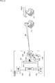
- the distance measuring device 11 in the upper part of FIG. 1 is composed of a control unit 31, an input unit 32, an output unit 33, a substrate 34, a light emitting unit 35, a focus lens 36, and a light receiving unit 37.
- the control unit 31 controls the entire operation of the distance measuring device 11.
- the control unit 31 controls the light emitting unit 35 based on the operation signal supplied from the input unit 32 to emit light for distance measurement (hereinafter referred to as distance measurement light) and collects the light via the focus lens 36. It shines, forms a range-finding light L1, and projects light onto an object 12 to be range-measured.
- distance measurement light light for distance measurement
- control unit 31 controls the light receiving unit 37 so that the distance measuring light L1 projected by the light emitting unit 35 emitting light receives the light reflected by the object 12.
- the control unit 31 reaches the object based on the light emission timing at which the distance measuring light is emitted by the light emitting unit 35 and the light receiving timing at which the reflected light reflected by the distance measuring light is received by the light receiving unit 37.
- Distance measurement is realized by calculating the distance from the round-trip time of the light to the object 12. That is, the control unit 31 realizes ToF (Time of Flight) distance measurement based on the light emission timing and the light reception timing. If the control unit 31 can obtain the distance to the object 12 from the round-trip time of the light to the object 12 based on the light emission timing and the light-receiving timing, the calculation is not necessarily essential, and corresponds to, for example, the round-trip time. It is also possible to obtain the distance to be the calculation result in advance and store it in a table or the like, and read the distance corresponding to the round-trip time from the table to obtain it.
- the input unit 32 is composed of an operation button operated when a user instructs distance measurement, a keyboard, an interface for receiving operation input from various devices, and the like, and generates and controls an operation signal according to the operation content. Input to unit 31.
- the output unit 33 is composed of a display and a speaker, and presents the distance measurement result supplied from the control unit 31 and information indicating whether or not the distance measurement is possible as audio or an image.
- the light emitting unit 35 and the light receiving unit 37 are provided on the substrate 34, are controlled by the control unit 31, and operate by the power supplied from a power source or the like (not shown).
- the light emitting unit 35 is composed of a laser diode or the like, is controlled by the control unit 31, and emits beam-shaped ranging light and irradiates it toward the focus lens 36 based on a signal supplied at a predetermined timing. ..
- the focus lens 36 collects the projected light on the light emitting unit 35 to form a range-finding light having a thickness of a predetermined spot diameter at a predetermined distance, and is an object to be measured. Irradiate toward 12.
- the focus lens 36 has a detachable structure, and is replaced with a focus lens having a plurality of focal lengths capable of condensing the light projected by the light emitting unit 35 to a predetermined spot diameter at various distances. By doing so, it is possible to switch and use it.
- the control unit 31 informs the output unit 33 of information on which focus lens 36 should be used. It may be presented.
- control unit 31 when the user inputs the distance D1 as the distance range information, the control unit 31 presents the information prompting the use of the focus lens 36 to the output unit 33, and when the distance D2 is input as the distance range information, the control unit 31 presents the information to the output unit 33.
- Information prompting the use of the focus lens 36' may be presented to the output unit 33.
- the light receiving unit 37 is composed of, for example, a CMOS (Complementary Metal Oxide Semiconductor) image sensor or the like, and the ranging light projected from the light emitting unit 35 receives the reflected light reflected by the object 12, and a signal corresponding to the light reception. Is output to the control unit 31.
- CMOS Complementary Metal Oxide Semiconductor
- the control unit 31 receives the light emission timing at which the light emitting unit 35 is controlled to emit the distance measuring light and the reflected light generated by the distance measuring light reflected by the object 12 by the light receiving unit 37.
- the round-trip time (Time of Flight) of light to the object 12 is measured based on the light receiving timing, and the distance to the object 12 based on the round-trip time is measured by calculation.
- control unit 31 outputs the distance measurement result when the distance to the object 12 can be measured to the output unit 33 and presents it.
- the object 12 does not exist within a predetermined distance, and the distance measurement light projected by the light emitting unit 35 emits light is diffused, so that the object 12 cannot receive the reflected light with sufficient intensity.
- the control unit 31 presents information indicating that the distance cannot be measured.
- the ranging light has a surface irradiance higher than a predetermined value on the surface of the object 12 and can be received by a predetermined number of pixels. It is a condition that the light is sufficiently bright and can be received as reflected light of a sufficient size, which is generated by being irradiated as a spot of a sufficient size.
- the focus lens 36 can sufficiently receive the reflected light reflected by the light receiving unit 37 on the surface of the object 12 existing at the distance D1 from the distance measuring device 11, for example.
- the light emitted by the light emitting unit 35 is condensed so that the range-finding light L1 having a sufficiently bright surface irradiance and a sufficiently large spot diameter SP1 is formed.
- the distance measuring light L1 can appropriately receive the reflected light reflected by the object 12, so that it is possible to realize an appropriate distance measuring.
- the distance measurement light L1 corresponds to the distance from the object 12. It diffuses and is reflected on the surface of the object 12'with a spot diameter of SP2, for example.
- the spot diameter SP2 becomes larger than the predetermined size, the surface irradiation illuminance of the spot diameter SP2 is reduced on the surface of the object 12', so that the light receiving portion 37 reflects with sufficient brightness. It cannot be received as light, and there is a risk that proper distance measurement will not be possible.
- the surface irradiance of the object 12'at the distance D2 has a sufficient brightness and a sufficient size.
- a focus lens 36' that can be focused as the ranging light L2 having a spot diameter of SP1 is provided, and the light emitted by the light emitting unit 35 is focused so as to suppress the spread.
- the focus lens 36' uses the light emitted by the light emitting unit 35 on the surface of the object 12' at a distance D2 with a surface irradiance of sufficient brightness and a sufficient magnitude. It is possible to collect light as distance measuring light L2 having a spot diameter of SP1.
- the light receiving unit 37 can receive the reflected light of sufficient brightness from the object 12', so that appropriate distance measurement can be realized.
- a focus lens having a spot diameter of SP1 that can obtain a surface irradiation irradiance of sufficient brightness at various distances is prepared. By switching as needed, it is possible to realize distance measurement at various distances.
- the focus lens 36 may be composed of one lens or a plurality of lens groups.
- FIG. 1 an example in which the focus lenses 36 and 36'form the distance measuring lights L1 and L2 having the spot diameter SP1 at the distances D1 and D2, respectively, has been described, but in reality, the distances D2 In, the light receiving portion 37 looks smaller by the distance longer than the distance D1.
- the spot diameter SP1 is the spot diameter that can be recognized as a sufficient size while obtaining sufficient surface irradiance.
- the surface irradiance that can be sufficiently recognized by the light receiving unit 37 can be obtained and recognized as a sufficient size. Since the formed spot diameter changes, it is necessary to consider the light intensity of the light emitting unit 35, the size of the light source, the light receiving sensitivity of the light receiving unit 37, and the like for the spot diameter formed by the ranging light.
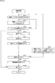
- step S11 the control unit 31 controls the output unit 33, presents information prompting the user to input the ranging range, and accepts the input.
- the user is prompted to input the distance measuring range, which is the range of the distance from the distance measuring device 11 to the object 12, and the user operates the input unit 32 until the distance measuring range is input. , The same process is repeated, and when the distance measuring range is input, the process proceeds to step S12.
- step S12 the control unit 31 presents information for designating the corresponding focus lens 36 and information for prompting the wearing of the focus lens 36 according to the distance measurement range input by operating the input unit 32.
- control unit 31 has a detachable focus lens 36 and a distance measuring range having a surface irradiation illuminance that allows the distance measuring light to be sufficiently received by the light receiving unit 37 and a spot diameter having a sufficiently large size. I remember the correspondence.
- the control unit 31 sets the spot diameter of the distance measuring light to the spot diameter SP1 at the distance D1 of the upper part of FIG. Information that specifies the focus lens 36 that focuses on is presented.
- the control unit 31 focuses the spot diameter of the distance measuring light on the spot diameter SP1 at the distance D2 in the lower part of FIG. Information that specifies the lens 36'is presented.
- a spot diameter having a surface irradiation illuminance that allows distance measurement light to be irradiated on the surface of the object 12 and sufficiently received by the light receiving unit 37 and a sufficient size is also referred to as an appropriate spot diameter.
- step S13 the control unit 31 determines whether or not the focus lens 36 has been attached by the user by operating the input unit 32, and if it is not considered to be attached, the process returns to step S12.
- steps S12 and S13 are repeated until it is considered that the focus lens 36 is attached.
- step S13 when the input unit 32 is operated and information indicating that the focus lens 36 is attached is input by the user, the process proceeds to step S14.
- step S14 the control unit 31 controls the light emitting unit 35 to emit the ranging light, and collects the distance measuring light through the focus lens 36 so as to have an appropriate spot diameter on the surface of the object 12. To form a range-finding light.
- step S15 the control unit 31 controls the light receiving unit 37 to receive the reflected light from the object 12 of the ranging light.
- step S16 the control unit 31 is based on the reciprocating time of the distance measuring light to the object 12 calculated from the light emission timing at which the light emitting unit 35 emits light and the light receiving timing at which the reflected light is received by the light receiving unit 37. The distance to the object 12 is measured.
- step S17 the control unit 31 determines whether or not the distance can be measured by the processing of steps S14 to S16. That is, the ranging light projected by the light emitted by the light emitting unit 35 is irradiated on the surface of the object 12 so as to have an appropriate spot diameter, and the reflected light generated thereby is received by the light receiving unit 37. , It is determined whether or not appropriate distance measurement is realized.
- step S17 If it is determined that the distance can be measured appropriately in step S17, the process proceeds to step S18.
- step S18 the control unit 31 controls the output unit 33 to present information on the distance to the object 12, which is the distance measurement result.
- step S19 the control unit 31 controls the input unit 32 to determine whether or not the end of the distance measurement process is instructed, and if the end is not instructed, the process returns to step S14.
- the distance measuring light is emitted and the reflected light from the object 12 is received, depending on the light emission timing and the light receiving timing.
- the process of measuring the distance to the object 12 and presenting the distance measurement result is repeated.
- step S19 when the end is instructed, the distance measurement process ends.
- step S17 when it is considered that the distance measurement is not possible, that is, for example, the object 12 exists at a position farther than the distance measurement range, the distance measurement light is diffused, and an appropriate spot diameter is formed on the surface of the object 12.
- the light receiving unit 37 when the reflected light darker than the predetermined brightness is received by the light receiving unit 37 due to the decrease in the surface irradiance, the light receiving timing of the light receiving unit 37 is not properly detected, so that the distance measurement is appropriate. Is considered impossible.
- the object 12 exists at a position sufficiently closer than the distance measuring range, and the reflected light on the surface of the distance measuring light object 12 is too bright, so that the level received by the light receiving unit 37 is saturated. As a result, distance measurement may not be possible even when the appropriate light reception timing cannot be detected.
- step S20 the process proceeds to step S20.
- step S20 the control unit 31 controls the output unit 33 to prevent distance measurement. Therefore, the control unit 31 presents information prompting confirmation as to whether or not the input distance measurement range is appropriate, and the process is performed in step S20. Return to S11.
- the distance measurement range input by the user may not be appropriate, so the user is prompted to confirm whether the input distance measurement range is appropriate, and the input of a new distance measurement range is accepted. Subsequent processing is repeated.
- steps S11 to S17 and S20 are repeated until the distance can be measured, and whether or not the distance measurement range is appropriate is confirmed, and the focus lens 36 according to the distance measurement range input after the confirmation is obtained. Switch and repeat distance measurement.
- the light receiving unit 37 can receive light at various distances. Since the object 12 is irradiated with the ranging light having a spot diameter having an appropriate brightness, it is possible to appropriately realize the ranging to the object 12 at various distances.
- the distance to the object 12 is too long, and the spot formed by the ranging light on the surface of the object has a spot diameter larger than the appropriate spot diameter, and sufficient surface irradiation illuminance cannot be obtained. It is possible to prevent the distance from becoming impossible.
- any of the indirect ToF (Time of Flight) method and the direct ToF method is used. May be good.
- the indirect ToF method is a method of calculating the distance to an object by detecting the flight time from when the irradiation light is emitted to when the reflected light is received as a phase difference.
- the directToF method is a method that directly measures the flight time from when the irradiation light is emitted to when the reflected light is received, and calculates the distance to the object.
- the distance measuring method based on the light emitting timing of the light emitting unit 35 and the light receiving timing of the light receiving unit 37 may be other than the ToF method, and may be, for example, the Structured Light method.
- the Structured Light method is a method of irradiating pattern light as irradiation light and calculating the distance to an object based on the distortion of the received pattern.
- the technique of the present disclosure may be applied not only to the distance measuring device but also to the surveillance camera.
- Second Embodiment By switching and using the focus lens 36 according to the distance to the object 12, the distance measuring light is irradiated so that an appropriate spot diameter is formed on the surface of the object 12 at various distances. In the above, an example of realizing distance measurement up to an object 12 in various distance measurement ranges has been described.
- the focus lens 36 may be moved to various positions with respect to the optical axis direction of the distance measuring light so that the distance measuring light is focused on an appropriate spot diameter at various distances.
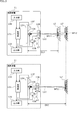
- FIG. 3 shows a configuration example of the distance measuring device 11 in which the distance measuring light is focused on an appropriate spot diameter at various distances.
- the distance measuring device 11 in the upper and lower stages of FIG. 3 is composed of a control unit 131, an input unit 132, an output unit 133, a substrate 134, a light emitting unit 135, a focus lens 136, a light receiving unit 137, and an actuator 138.
- the control unit 131, the input unit 132, the output unit 133, the substrate 134, the light emitting unit 135, the focus lens 136, and the light receiving unit 137 are the control unit 31, the input unit 32, the output unit 33, the substrate 34, and the light emitting unit in FIG. Since the configuration is basically the same as that of the unit 35, the focus lens 36, and the light receiving unit 37, the description thereof will be omitted as appropriate.
- the distance measuring device 11 of FIG. 3 differs from the distance measuring device 11 of FIG. 1 in that an actuator 138 is newly provided.
- the actuator 138 is controlled by the control unit 131, and the focus lens 136 is oriented in the arrow Z direction in the drawing so that an appropriate spot diameter is formed according to the ranging range in order to realize the ranging of the object 12. As shown by, the light emitting unit 135 is moved back and forth with respect to the optical axis direction.
- the actuator 138 moves the focus lens 136 to the position Z1, so that an appropriate spot diameter SP11 is generated on the surface of the object 12 at the distance D11.
- Light L11 forms.
- the distance measurement target is an object 12'at a distance D12 (> D11) farther than the distance D11
- the distance measurement light L11 diffuses according to the distance from the object 12. Then, for example, it will be reflected on the surface of the object 12'in the state of the spot diameter SP12 (> Sp11).
- the spot diameter SP12 is larger than the appropriate spot diameter SP11, the surface irradiation illuminance is lowered on the surface of the object 12'and dark reflected light is received by the light receiving unit 137, which is appropriate. It may not be able to receive light as reflected light of brightness, and proper distance measurement may not be possible.
- the control unit 131 controls the actuator 138 to move the focus lens 136 from the position Z1 to the position Z2.
- the distance measuring light L12 is suppressed from spreading and focused so that the spot diameter SP11 is appropriate for the object 12'at the distance D12.
- the focus lens 136 can collect the light emitted by the light emitting unit 135 on the surface of the object 12'at the distance D12 so as to have an appropriate spot diameter SP11. ..
- the light receiving unit 137 can receive the reflected light of sufficient brightness from the object 12', so that appropriate distance measurement can be realized.
- the focus lens 136 can be focused on an appropriate spot diameter SP11 in various ranging ranges. This makes it possible to realize distance measurement in various distance measurement ranges.
- the focus lens 136 may be composed of one lens or a plurality of lens groups. Further, in the present specification, an example in which the spread of the ranging light is suppressed by moving the focus lens 136 from the position Z1 to the position Z2 has been described, but the movement for expanding the spread of the ranging light has been described. The direction and the moving direction for suppressing the spread of the ranging light may be reversed depending on the configuration of the focus lens 136.
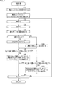
- step S31 the control unit 131 controls the output unit 133, presents information prompting the user to input the ranging range, and accepts the input.
- step S32 the control unit 131 controls the actuator 138 to adjust the focus lens 136 so as to move the focus lens 136 to the corresponding position according to the distance measurement range input by operating the input unit 132.
- control unit 131 stores the correspondence between the position of the focus lens 136 in the arrow Z direction and the distance measuring range in which the distance measuring light is used as the spot diameter. Therefore, for example, in the case of the upper part of FIG. 3, when the distance measuring range corresponds to the distance D11, the control unit 31 controls the actuator 138 to appropriately transmit the distance measuring light at the distance D11 of FIG. The focus lens 36 is moved to the position Z1 that focuses on the spot diameter SP11.
- the control unit 131 controls the actuator 138 to appropriately transmit the distance measuring light at the distance D12 of the lower part of FIG.
- the focus lens 136 is moved to the position Z2 that focuses on the spot diameter SP11.
- step S33 the control unit 131 controls the light emitting unit 135 to emit the ranging light to the spot diameter SP11 at a distance corresponding to the ranging range toward the object 12 via the focus lens 136. It is focused and projected so that it becomes.
- step S34 the control unit 131 controls the light receiving unit 137 to receive the reflected light from the object 12 of the ranging light.
- step S35 the control unit 131 is based on the round-trip time to the object 12 of the ranging light calculated from the timing when the light emitting unit 135 is made to emit light and the timing when the reflected light is received by the light receiving unit 137. The distance to the object 12 is measured.
- step S36 the control unit 131 determines whether or not the distance can be measured by the processing of steps S33 to S35. That is, the ranging light projected by the light emitted by the light emitting unit 135 is irradiated on the surface of the object 12 with an appropriate spot diameter, and is received by the light receiving unit 137 as reflected light of appropriate brightness, so that appropriate measurement is performed. Whether or not the distance is realized is determined.
- step S36 If it is determined that the distance can be measured appropriately in step S36, the process proceeds to step S37.
- step S37 the control unit 131 controls the output unit 133 to present information on the distance to the object 12, which is the distance measurement result.
- step S36 If it is determined that the distance cannot be measured in step S36, the process proceeds to step S38.
- step S38 the control unit 131 controls the output unit 133 to prevent distance measurement, and therefore presents information prompting confirmation as to whether or not the input distance measurement range is appropriate.
- step S39 the control unit 131 determines whether or not the input unit 132 is operated to instruct the focus lens 136 to move to a position farther in the distance measurement range.
- step S39 when the input unit 132 is operated and it is deemed that there is an instruction to move the focus lens 136 to a position farther in the focusing range, the process proceeds to step S40.
- step S40 the control unit 131 controls the actuator 138 to adjust the focus lens 136 so as to move the focus lens 136 to a position where the spread of the distance measurement light is narrowed according to the instructed distance measurement range.
- step S39 when the input unit 132 is operated and it is deemed that there is no instruction to move the focus lens 136 to a position farther in the ranging range, the process proceeds to step S41.
- step S41 the control unit 131 determines whether or not the input unit 132 is operated to instruct the focus lens 136 to move to a position closer to the distance measurement range.
- step S41 when the input unit 132 is operated and it is deemed that there is an instruction to move the focus lens 136 to a position closer to the focusing range, the process proceeds to step S42.
- step S42 the control unit 131 controls the actuator 138 to move the focus lens 136 to a position where the spread of the ranging light is widened according to the instructed ranging range.
- step S42 If the input unit 132 is operated in step S41 and it is considered that there is no instruction to move the focus lens 136 to a position closer to the focusing range, the process of step S42 is skipped.
- step S43 the control unit 131 controls the input unit 132 to determine whether or not the end of the distance measurement process is instructed, and if the end is not instructed, the process returns to step S33.
- steps S33 to S43 are repeated until the end is instructed, the distance measuring light is emitted and the reflected light from the object 12 is received, and the object is subjected to the light emission timing and the light receiving timing.
- the distance measurement is performed up to, and the process of presenting the distance measurement result is repeated.
- the distance measurement target in the desired distance measurement range can be obtained.
- the distance to the object 12 is measured.
- step S43 when the end is instructed, the distance measurement process ends.
- the user can arbitrarily set the ranging range that is the distance to the desired object 12, and can switch the position of the focus lens 136 according to the ranging range.
- First variant of the second embodiment >> ⁇ Modification example of distance measurement processing>
- the ranging light is focused so as to have an appropriate spot diameter such that reflected light suitable for ranging is generated in the ranging range desired by the user.
- the spread of the ranging light may be adjusted according to the illuminance of the spot of the ranging light received by the unit 137 as the reflected light.
- the illuminance of the spot of the ranging light received as reflected light by the light receiving unit 137 is high when the ranging range by the focus lens 136 is close to the distance of the object 12, and the ranging range by the focus lens 136 is the object 12. Far and low with respect to the distance of.
- the ranging range by the focus lens 136 is close to the distance of the object 12. By widening the spread and reducing the illuminance, the distance measurement range can be approached.
- the ranging range by the focus lens 136 is far from the distance of the object 12.
- the distance measuring device 11 Since the basic configuration of the distance measuring device 11 is the same as that of the distance measuring device 11 of FIG. 3, the description thereof will be omitted.
- step S61 the control unit 131 controls the actuator 138 to adjust the focus lens 136 to move to the initial position corresponding to the default ranging range.
- step S62 the control unit 131 controls the light emitting unit 135 to emit the ranging light, and is appropriate at a distance corresponding to the initial value of the ranging range toward the object 12 via the focus lens 136.
- the light is focused and projected so that the spot diameter is large.
- step S63 the control unit 131 controls the light receiving unit 137 to receive the reflected light from the object 12 of the ranging light.
- step S64 the control unit 131 is based on the reciprocating time of the distance measuring light to the object 12 calculated from the light emission timing at which the light emitting unit 135 is made to emit light and the light receiving timing at which the reflected light is received by the light receiving unit 137. The distance to the object 12 is measured.
- step S65 the control unit 131 determines whether or not the distance can be measured by the processing of steps S62 to S64. That is, the ranging light projected by the light emitted by the light emitting unit 135 is irradiated on the surface of the object 12 with an appropriate spot diameter, and is received by the light receiving unit 137 as reflected light of appropriate brightness, so that appropriate measurement is performed. Whether or not the distance is realized is determined.
- step S65 If it is determined that the distance can be measured appropriately in step S65, the process proceeds to step S66.
- step S66 the control unit 131 controls the output unit 133 to present information on the distance to the object 12, which is the distance measurement result.
- step S67 the control unit 131 controls the input unit 132 to determine whether or not the end of the distance measurement process is instructed, and if the end is not instructed, the process returns to step S62.
- steps S62 to S67 are repeated until the end is instructed, the light emission of the ranging light and the reflected light from the object 12 are received, and the object is reached according to the respective timings.
- the distance measurement is performed, and the process of presenting the distance measurement result is repeated.
- step S67 when the end is instructed, the distance measurement process ends.
- step S65 If it is determined that the distance cannot be measured in step S65, the process proceeds to step S68.
- step S68 the control unit 131 controls the output unit 133 to present information indicating a state in which distance measurement is not possible.
- step S69 the control unit 131 determines whether or not the illuminance in the reflected light of the spot of the ranging light received by the light receiving unit 137 is lower than the predetermined lower limit value and the object 12 is farther than the predetermined distance range. To do.
- step S69 when the illuminance in the reflected light of the spot of the ranging light received by the light receiving unit 137 is lower than the predetermined lower limit value and the object 12 is considered to be farther than the predetermined distance range, the process is performed in step S69. Proceed to S70.
- step S70 the control unit 131 controls the actuator 138 to narrow the spread of the ranging light according to the difference between the spot illuminance and the predetermined lower limit value, reduce the spot diameter, and reduce the surface irradiance.
- the focus lens 136 is moved to a position where the illuminance is raised.
- step S69 if the illuminance in the reflected light of the spot of the ranging light received by the light receiving unit 137 is not lower than the predetermined lower limit value, the process proceeds to step S71.
- step S71 the control unit 131 determines whether or not the illuminance in the reflected light of the spot of the ranging light received by the light receiving unit 137 is higher than the predetermined upper limit value and the object 12 is closer than the predetermined distance range. To do.
- step S71 when the illuminance in the reflected light of the spot of the ranging light received by the light receiving unit 137 is higher than the predetermined upper limit value and the object 12 is considered to be closer than the predetermined distance range, the process is performed in step S71. Proceed to S72.
- step S72 the control unit 131 controls the actuator 138 to widen the spread of the ranging light and increase the spot diameter according to the difference between the illuminance of the spot and the predetermined upper limit value. Then, the focus lens 136 is moved to a position where the surface irradiance is lowered.
- step S71 if the illuminance in the reflected light of the spot of the ranging light received by the light receiving unit 137 is not higher than the predetermined upper limit value, the process of step S72 is skipped.
- the focus lens 136 is moved so that the spot diameter is adjusted so as to have an appropriate illuminance according to the illuminance of the spot, so that the user can measure the distance to the object to be measured. It is possible to appropriately realize the distance measurement to the object 12 at various distances without being conscious of the range.
- a second modification of the second embodiment >> ⁇ Modification example related to the configuration of the ranging device>
- the distance measuring light emitted by the light emitting unit 135 is focused by the focus lens 136 and irradiated to the object 12 to be distance measured.
- a mesh or a line has been described.
- a DoE (diffraction optical element) that forms a dot-shaped light distribution pattern may be provided, and the distance may be measured by receiving the light distribution pattern formed by the DoE.
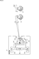
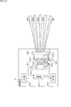
- FIG. 6 is a modified example of the configuration of the distance measuring device 11 provided with the diffractive optical element.
- the distance measuring device 11 of FIG. 6 is composed of a control unit 231, an input unit 232, an output unit 233, a substrate 234, a light emitting unit 235, a focus lens 236, a light receiving unit 237, an actuator 238, and a DoE239.
- the control unit 231, the input unit 232, the output unit 233, the substrate 234, the light emitting unit 235, the focus lens 236, the light receiving unit 237, and the actuator 238 are the control unit 131, the input unit 132, the output unit 133, and the substrate in FIG. Since the configuration is basically the same as that of 134, the light emitting unit 135, the focus lens 136, the light receiving unit 137, and the actuator 138, the description thereof will be omitted as appropriate.
- the distance measuring device 11 of FIG. 6 differs from the distance measuring device 11 of FIG. 3 in that DoE239 is newly provided.
- the DoE239 is generated by emitting light from the light emitting unit 235, and the light collected through the focus lens 236 is applied to a diffraction grating to provide a light distribution pattern such as a mesh pattern, a line pattern, a stripe pattern, and a dot pattern. Is converted to, and the object 12 to be distanced is irradiated as a plurality of beam-shaped distance measuring lights.
- An example of conversion to B1 to Bn is shown.
- the dots SP101 to SP116 are irradiated by DoE239, if the output power of the light emitting unit 235 is the same, the respective dots SP101 to SP116 are compared with the surface irradiance in the case of uniformly diffusing. Since the surface irradiation illuminance becomes large, it becomes possible to realize distance measurement of a distant object.
- the arrow of the focus lens 236 is also used by the actuator 238 so that the spread angle ⁇ 1 is changed so that the spot diameter at which sufficient brightness of the surface irradiation illuminance can be obtained is obtained for the distance measuring device 11 of FIG.
- the point of changing the position in the Z direction is the same as in FIG.
- the ROI (Region of Interest)
- the light receiving timing of only the dots belonging to the ROI is acquired, and the ROI is set to Only the distance measurement of the dots to which they belong may be performed.
- the ROI may be fixed in a cohesive area such as a row unit or a specific pattern (grid, etc.), and the entire surface may not be measured for discrimination.
- the distance measurement process is the same as the process described with reference to FIGS. 4 and 5, so the description thereof will be omitted.
- the distance measurement of the object 12 is realized for the region on each dot, but the distance measurement is not possible for the other regions. Therefore, the resolution of the area to be measured is low.
- FIG. 7 is a configuration example of the distance measuring device 11 in which the distance measurement is repeated while changing the position of the pattern to increase the resolution of the area to be measured.
- the distance measuring device 11 of FIG. 7 is composed of a control unit 331, an input unit 332, an output unit 333, a substrate 334, a light emitting unit 335, a focus lens 336, a light receiving unit 337, actuators 338, 339, and DoE340.
- the control unit 331, the input unit 332, the output unit 333, the substrate 334, the light emitting unit 335, the focus lens 336, the light receiving unit 337, the actuator 338, and the DoE 340 are the control unit 231, the input unit 232, and the output unit 233 in FIG. ,
- the substrate 234, the light emitting unit 235, the focus lens 236, the light receiving unit 237, the actuator 238, and the DoE 239 have basically the same configuration, and the description thereof will be omitted as appropriate.
- the distance measuring device 11 of FIG. 7 differs from the distance measuring device 11 of FIG. 6 in that the actuator 339 is provided.
- the actuator 339 is controlled by the control unit 331, and the focus lens 336 is orthogonal to the optical axis of the light emitted by the light emitting unit 35, and is indicated by the vertical direction indicated by the arrow V direction in the drawing and the arrow H direction. Move to at least one of the horizontal directions.
- the dots SP101 to SP116 are moved in the arrow V'direction and the arrow H'. It is possible to move in the direction.
- the region where the object 12 to be distance-measured exists is regarded as the ROI (Region of Interest), and the light receiving timing of that region is regarded as ROI (Region of Interest).
- the ROI may be fixed in a cohesive area such as a row unit or a specific pattern (grid, etc.), and the entire surface measurement for discrimination may not be performed. The read time can be shortened and the processing speed can be improved.
- step S101 the control unit 331 counts one step of the minimum moving distance when the positions of the dots SP101 to SP116 formed by the DoE340 are changed to at least one of the arrow H direction and the arrow V direction. Initializes the counter K of.
- step S102 the control unit 331 controls the actuator 338 to move the focus lens 336 to the initial position corresponding to the default ranging range with respect to the arrow Z direction, and also controls the actuator 339 to control the arrow.
- the focus lens 336 is moved so that the dots SP101 to SP116 are formed at positions corresponding to the counter K in the V direction and the arrow H direction.
- step S103 the control unit 331 controls the light emitting unit 335 to emit the ranging light, and the dots SP101 to SP116 are formed toward the object 12 via the focus lens 336 and the DoE340. A range-finding light consisting of a pattern is projected.
- step S104 the control unit 331 controls the light receiving unit 337 to receive the reflected light from the object 12 of the ranging light.
- step S105 the control unit 331 reads out the light reception timing at which the reflected light from the ROI, such as the region where the object 12 to be distance-measured exists, is received from the signals received by the light receiving unit 337.
- step S106 the control unit 331 reciprocates the distance measurement light to the object 12 calculated from the light emission timing at which the light emitting unit 335 in the ROI emits light and the light receiving timing at which the reflected light is received by the light receiving unit 337.
- the distance to the object 12 is measured based on.
- step S107 the control unit 331 determines whether or not the distance can be measured by the processing of steps S103 to S106. That is, the ranging light projected by the light emitted by the light emitting unit 335 is irradiated on the surface of the object 12 so that each of the dots SP101 to SP116 has an appropriate spot diameter, and the light receiving unit is reflected as reflected light having an appropriate brightness. By receiving light from the 337, it is determined whether or not appropriate distance measurement has been realized.
- step S107 If it is determined that the distance can be measured appropriately in step S107, the process proceeds to step S108.
- step S108 the control unit 331 controls the output unit 333 to present information on the distance to the object 12, which is the distance measurement result.
- step S109 the control unit 331 increments the counter K by 1.
- step S110 the control unit 331 determines whether or not the distance measurement at all the positions is completed based on whether or not the counter K has a value one larger than the maximum value.
- step S110 If it is considered that the distance measurement at all positions has not been completed in step S110, the process returns to step S102.
- step S107 If it is determined that the distance cannot be measured in step S107, the process proceeds to step S111.
- step S111 the control unit 331 determines whether or not the illuminance in the reflected light of the spot of the ranging light received by the light receiving unit 337 is lower than the predetermined lower limit value and the object 12 is farther than the predetermined distance range. To do.
- step S111 the illuminance of the reflected light at the spot formed as dots corresponding to the light distribution pattern of the ranging light received by the light receiving unit 337 is lower than the predetermined lower limit value, and the object 12 is below the predetermined distance range. If deemed distant, the process proceeds to step S112.
- step S112 the control unit 331 controls the actuator 338 to move the focus lens 336 in the Z direction so as to narrow the spread of the ranging light according to the difference between the spot illuminance and the predetermined lower limit value.
- the process proceeds to step S110.
- step S111 if the illuminance in the reflected light of the spot of the ranging light received by the light receiving unit 337 is not lower than the predetermined lower limit value, the process proceeds to step S113.
- step S113 the control unit 331 has the illuminance of the reflected light at the spot formed as dots corresponding to the light distribution pattern of the distance measuring light received by the light receiving unit 337 higher than a predetermined upper limit value, and the object 12 is predetermined. Determine if it is closer than the distance range of.
- step S113 the illuminance of the reflected light at the spot formed by dots according to the light distribution pattern of the ranging light received by the light receiving unit 337 is higher than the predetermined upper limit value, and the object 12 is within the predetermined distance range. If is also considered close, the process proceeds to step S114.
- step S114 the control unit 331 controls the actuator 338 to move the focus lens 336 to a position where the spread of the ranging light is widened according to the difference between the spot illuminance and the predetermined upper limit value. Moving in the direction, the process proceeds to step S110.
- step S113 if the illuminance in the reflected light of the spot of the ranging light received by the light receiving unit 337 is not higher than the predetermined upper limit value, the process of step S114 is skipped.
- step S110 when it is considered that the distance measurement at all the positions is completed, the process proceeds to step S115.
- step S115 the control unit 331 controls the output unit 333 to output and present the distance measurement result repeatedly acquired while changing the positions of the stored dots SP101 to SP116.
- step S116 the control unit 331 controls the input unit 332 to determine whether or not the end of the distance measurement process is instructed, and if the end is not instructed, the process returns to step S101. That is, the processes of steps S101 to S116 are repeated until the end is instructed.
- step S116 when the end is instructed, the distance measurement process ends.
- the focus lens 336 is moved so that the spot diameter is adjusted so as to have an appropriate illuminance according to the illuminance of the spot as dots forming the light distribution pattern formed by DoE340. Therefore, the user can appropriately realize the distance measurement to the object 12 at various distances without being aware of the distance measurement range to the object to be distance-measured.
- the position of each dot irradiated by the light distribution pattern formed by DoE340 is possible to increase the resolution of the distance measurement result by repeating the distance measurement while changing the distance in at least one of the arrow H'direction and the arrow V'direction'.
- the ranging light BB having a spreading angle ⁇ 11 may be formed so that a line-shaped pattern BSP is formed in the horizontal direction.
- FIG. 9 shows a configuration example of the distance measuring device 11 in which the distance measuring light BB having a spreading angle ⁇ 11 is formed so that the line-shaped pattern BSP is formed in the horizontal direction.
- the distance measuring device 11 of FIG. 9 is composed of a control unit 351, an input unit 352, an output unit 353, a substrate 354, a light emitting unit 355, a focus lens 356, a light receiving unit 357, actuators 358, 359, and DoE 360.
- the control unit 351 and the input unit 352, the output unit 353, the substrate 354, the light emitting unit 355, the focus lens 356, the light receiving unit 357, the actuators 358, 359, and the DoE 360 of FIG. 9 are the control unit 331 and the input unit of FIG. Since the configuration is basically the same as that of the 332, the output unit 333, the substrate 334, the light emitting unit 335, the focus lens 336, the light receiving unit 337, the actuators 338, 339, and the DoE340, the description thereof will be omitted as appropriate.
- the pattern BSP in FIG. 9 is formed in a line shape in the horizontal direction, and as shown by the arrow, it is only necessary to repeat the distance measurement while moving the object 12 stepwise in the vertical direction.
- the light distribution pattern formed by DoE360 is not limited to the one formed in a line shape in the horizontal direction, and may be formed in a line shape in another direction, for example, is formed in a line shape in the vertical direction. In this way, the distance measurement may be repeated while moving stepwise in the direction of the arrow H.
- the distance measurement process is the same as the process described with reference to the flowchart of FIG. 8, so the description thereof will be omitted.
- Second variant of the third embodiment >> In the above, an example in which a line-shaped light distribution pattern is formed by DoE360 has been described, but the DoE is arranged so that a beam-shaped ranging light having a uniform light beam thickness is formed regardless of the distance. When the light is received as reflected light in the object 12, the light receiving unit may also be able to receive light by a plurality of pixels.
- a beam-shaped ranging light CB having no spreading angle and having a uniform width regardless of the distance is formed so that a line-shaped pattern CBSP is formed in the horizontal direction. You may do so.
- FIG. 10 it is shown that the width BW1 and the width BW2 of the distance measuring light CB are formed in the same state regardless of the distance.
- the pattern CBSP is formed in the light receiving portion to have a thickness that allows the light to be received by a plurality of pixels.
- FIG. 10 shows distance measurement in which a beam-shaped distance measuring light CB having no spreading angle and having a uniform diameter regardless of the distance is formed so that a line-shaped pattern CBSP is formed in the horizontal direction.
- a configuration example of the device 11 is shown.
- the distance measuring device 11 of FIG. 10 is composed of a control unit 371, an input unit 372, an output unit 373, a substrate 374, a light emitting unit 375, a focus lens 376, a light receiving unit 377, actuators 378, 379, and DoE380.
- the control unit 371, input unit 372, output unit 373, substrate 374, light emitting unit 375, focus lens 376, light receiving unit 377, actuators 378, 379, and DoE380 of FIG. 10 are the control unit 351 and input unit of FIG. Since the configuration is basically the same as that of the 352, the output unit 353, the substrate 354, the light emitting unit 355, the focus lens 356, the light receiving unit 357, the actuators 358, 359, and the DoE 360, the description thereof will be omitted as appropriate.
- the focus lens 376 is also shown in the arrow V direction. This can be achieved simply by repeating distance measurement while moving in the vertical direction at predetermined intervals.
- the width of the ranging light CB is uniform regardless of the distance.
- the width of the pattern CBSP is set to be a width that can be received by a plurality of pixels in the light receiving unit 377 when reflected by the object 12, so that the light receiving sensitivity in the light receiving unit 377 can be improved. It is possible to realize distance measurement at a distance and improve distance measurement accuracy.
- the distance measurement process is the same as the process described with reference to the flowchart of FIG. 8, so the description thereof will be omitted.
- the light is distributed by the DoE380 so as to form a beam-shaped ranging light having a uniform width regardless of the distance, and when the light is received as the reflected light in the object 12, the light receiving portion also has a plurality of pixels. An example of enabling light reception has been described.
- the light receiving unit can also receive light from a plurality of pixels, the thickness (width) of the distance measuring light does not have to be uniform according to the distance.
- a ranging light PB having a spreading angle may be formed so that a line-shaped pattern PBSP is formed in the horizontal direction.
- the pattern PBSP is formed in the light receiving portion to have a width that allows the light to be received by a plurality of pixels.
- FIG. 11 shows a configuration example of the distance measuring device 11 in which the distance measuring light PB having a spreading angle is formed so that the line-shaped pattern PBSP is formed in the horizontal direction.
- the distance measuring device 11 of FIG. 11 is composed of a control unit 391, an input unit 392, an output unit 393, a substrate 394, a light emitting unit 395, a focus lens 396, a light receiving unit 397, actuators 398, 399, and DoE400.
- the control unit 391, input unit 392, output unit 393, substrate 394, light emitting unit 395, focus lens 396, light receiving unit 397, actuator 398, 399, and DoE400 in FIG. 11 are the control unit 371 and input unit in FIG. Since the configuration is basically the same as that of the 372, the output unit 373, the substrate 374, the light emitting unit 375, the focus lens 376, the light receiving unit 377, the actuators 378, 379, and the DoE380, the description thereof will be omitted as appropriate.
- the focus lens 396 is also shown in the arrow V direction. This can be achieved simply by repeating distance measurement while moving in the vertical direction at predetermined intervals.
- the ranging light PB has a spreading angle, but a light distribution pattern composed of a pattern PBSP having a predetermined width is formed on the object 12.
- the width of the pattern PBSP is set to be a width that can be received by a plurality of pixels in the light receiving unit 377 when reflected by the object 12, so that the light receiving sensitivity in the light receiving unit 377 can be improved. It is possible to realize distance measurement at a distance and improve distance measurement accuracy.
- the distance measurement process is the same as the process described with reference to the flowchart of FIG. 8, so the description thereof will be omitted.
- FIG. 12 shows a configuration example of the ranging device 11 using a VCSEL as the light emitting unit.
- the distance measuring device 11 of FIG. 12 is composed of a control unit 411, an input unit 412, an output unit 413, a substrate 414, a light emitting unit 415, a focus lens 416, a light receiving unit 417, actuators 418, 419, and DoE 420.
- the control unit 411, input unit 412, output unit 413, substrate 414, light emitting unit 415, focus lens 416, light receiving unit 417, actuators 418, 419, and DoE 420 in FIG. 12 are the control unit 391 and input unit in FIG. Since the configuration is basically the same as that of the 392, the output unit 393, the substrate 394, the light emitting unit 395, the focus lens 396, the light receiving unit 397, the actuators 398, 399, and the DoE400, the description thereof will be omitted as appropriate.
- the distance measuring device 11 of FIG. 12 differs from the distance measuring device 11 of FIG. 11 in that the light emitting unit 415 is composed of a VCSEL and the focus lens 416 is a plurality of collimator lenses 416-1 to 416-n. It is a point composed of more.
- the light emitting unit 415 is composed of the VCSEL, a planar light source is formed. Then, the light emitted from the planar light source is converted into parallel light by the plurality of collimator lenses 416-1 to 416-n forming the focus lens 416. Further, the parallel light is converted by the DoE420 into distance measuring lights B51 to Bm composed of, for example, dot-shaped pattern light as shown in FIG. 12, and is irradiated to the distance measuring target.
- the spread angle and irradiation direction of the distance measuring light are controlled by the actuators 418 and 419.
- the distance measurement process is the same as the process described with reference to the flowchart of FIG. 8, so the description thereof will be omitted.
- FIG. 13 shows a configuration example of the distance measuring device 11 using a MEMS mirror instead of DoE as a configuration for forming a light distribution pattern.
- the distance measuring device 11 of FIG. 13 is composed of a control unit 451, an input unit 452, an output unit 453, a substrate 454, a light emitting unit 455, a focus lens 456, a light receiving unit 457, actuators 458, 459, and a MEMS mirror 460.
- control unit 451 and the input unit 452, the output unit 453, the substrate 454, the light emitting unit 455, the focus lens 456, and the light receiving unit 457 of FIG. 13 are the control unit 331, the input unit 332, the output unit 333, and the substrate of FIG. Since the configuration is basically the same as that of the 334, the light emitting unit 335, the focus lens 336, and the light receiving unit 337, the description thereof will be omitted as appropriate.
- the distance measuring device 11 of FIG. 13 differs from the distance measuring device 11 of FIG. 7 in that a MEMS mirror 460 is provided instead of the DoE 340, and the light emitting unit 455 corresponds to the MEMS mirror 460. It is a point to irradiate the emitted light.
- the MEMS mirror 460 has mirrors 460 m-1 to 460 mx formed on the surface thereof, and reflects the light emitted from the light emitting unit 455 incident through the focus lens 456.
- a light distribution pattern is formed by generating a plurality of ranging lights B101 to Bx.
- the focus lens 456 can adjust the spread angle of the ranging light B101 to Bx by adjusting the position in the arrow Z direction by the actuator 458.
- the focus lens 456 can change the irradiation direction of the ranging light B101 to Bx by changing the position in the arrow V and H directions by the actuator 459.
- the light distribution pattern can be changed according to the shape and arrangement pattern of the mirrors 460m-1 to 460mx in FIG.
- FIG. 14 an example in which a light distribution pattern of a dot pattern is formed is shown, but when the mirror 460 m is formed in a mesh shape, the light distribution pattern is formed in a mesh pattern and is formed in a line shape. At that time, the light distribution pattern is a line pattern.
- the light distribution pattern can be changed substantially in the same manner as when DoE is used, depending on the shape and arrangement pattern of the mirror 460 m.
- the distance measurement process is the same as the process described with reference to the flowchart of FIG. 8, so the description thereof will be omitted.
- the focus lens 336,356,376,396,416,456 is moved in the direction of the arrow V and the direction of the arrow H to repeat the distance measurement while changing the direction of the distance measurement light.
- the distance measurement may be repeated while changing the direction of the distance measurement light, that is, the position of the spot on the object 12.
- the distance measuring device of the present disclosure it is possible to realize a distance measurement by the ToF (Time of Flight) method.
- ToF Time of Flight
- Example of execution by software can be executed by hardware, but can also be executed by software.
- the programs that make up the software can execute various functions by installing a computer embedded in dedicated hardware or various programs. It is installed from a recording medium on a possible, eg, general purpose computer.
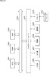
- FIG. 15 shows a configuration example of a general-purpose computer.
- This personal computer has a built-in CPU (Central Processing Unit) 1001.
- the input / output interface 1005 is connected to the CPU 1001 via the bus 1004.
- a ROM (Read Only Memory) 1002 and a RAM (Random Access Memory) 1003 are connected to the bus 1004.
- the input / output interface 1005 includes an input unit 1006 including an input device such as a keyboard and a mouse for which a user inputs an operation command, an output unit 1007 for outputting a processing operation screen and an image of a processing result to a display device, a program, and various data.
- a storage unit 1008 consisting of a hard disk drive or the like for storing, a LAN (Local Area Network) adapter or the like, and a communication unit 1009 for executing communication processing via a network represented by the Internet are connected.
- magnetic disks including flexible disks
- optical disks including CD-ROM (Compact Disc-Read Only Memory), DVD (Digital Versatile Disc)
- optical magnetic disks including MD (Mini Disc)
- a drive 1010 that reads and writes data to and from a removable storage medium 1011 such as a memory is connected.
- the CPU 1001 is read from a program stored in the ROM 1002 or a removable storage medium 1011 such as a magnetic disk, an optical disk, a magneto-optical disk, or a semiconductor memory, installed in the storage unit 1008, and loaded from the storage unit 1008 into the RAM 1003. Various processes are executed according to the program.
- the RAM 1003 also appropriately stores data and the like necessary for the CPU 1001 to execute various processes.
- the CPU 1001 loads the program stored in the storage unit 1008 into the RAM 1003 via the input / output interface 1005 and the bus 1004 and executes the above-described series. Is processed.
- the program executed by the computer can be recorded and provided on the removable storage medium 1011 as a package medium or the like, for example. Programs can also be provided via wired or wireless transmission media such as local area networks, the Internet, and digital satellite broadcasting.
- the program can be installed in the storage unit 1008 via the input / output interface 1005 by mounting the removable storage medium 1011 in the drive 1010. Further, the program can be received by the communication unit 1009 via a wired or wireless transmission medium and installed in the storage unit 1008. In addition, the program can be pre-installed in the ROM 1002 or the storage unit 1008.
- the program executed by the computer may be a program that is processed in chronological order according to the order described in this specification, or may be a program that is processed in parallel or at a necessary timing such as when a call is made. It may be a program in which processing is performed.
- the CPU 1001 in FIG. 15 is the control unit 31 of FIG. 1, the control unit 131 of FIG. 3, the control unit 231 of FIG. 6, the control unit 331 of FIG. 7, the control unit 351 of FIG. 9, and the control unit 371 of FIG.
- the functions of the control unit 391 of FIG. 11, the control unit 411 of FIG. 12, and the control unit 451 of FIG. 13 are realized.
- the system means a set of a plurality of components (devices, modules (parts), etc.), and it does not matter whether all the components are in the same housing. Therefore, a plurality of devices housed in separate housings and connected via a network, and a device in which a plurality of modules are housed in one housing are both systems. ..
- the present disclosure can have a cloud computing configuration in which one function is shared by a plurality of devices via a network and jointly processed.
- each step described in the above flowchart can be executed by one device or shared by a plurality of devices.
- one step includes a plurality of processes
- the plurality of processes included in the one step can be executed by one device or shared by a plurality of devices.
- the present disclosure may also have the following configuration.
- a light emitting unit that emits light and functions as a light source
- a condensing unit that condenses the light emitted by the light emitting unit to form distance measurement light
- a condensing unit that condenses the light emitted by the light emitting unit to form distance measurement light
- a condensing unit that receives the reflected light reflected by the distance measuring light on the object to be measured.
- the distance to the object is measured based on the light emitting timing at which the light is emitted by the light emitting unit and the light receiving timing at which the reflected light is received by the light receiving unit.
- a distance measuring device equipped with a control unit.
- the light collecting unit collects the light emitted by the light emitting unit, and the reflected light generated by reflecting the light at a predetermined distance in the optical axis direction of the light is received by the light receiving unit.
- the distance measuring device according to ⁇ 1> which forms distance measuring light so as to have a predetermined spot diameter at the predetermined distance so as to be possible.
- the light collecting unit has a plurality of light collecting units according to the distance to the object and can be exchanged according to the distance to the object to be measured. .. ⁇ 4>
- the condensing unit further includes a first actuator that moves the position of the light emitted by the light emitting unit in the optical axis direction.
- the control unit controls the first actuator to adjust the position of the light collecting unit, so that the reflected light is emitted according to the distance to the object.
- the distance measuring device according to ⁇ 1>, wherein the distance measuring device is formed by adjusting the degree of condensing the light emitted by the light emitting unit so that the light receiving unit can receive light.
- the control unit controls the first actuator based on the specified distance so as to form a predetermined spot diameter that can be received by the light receiving unit in the vicinity of the specified distance.
- the distance measuring device wherein the position of the condensing unit is adjusted so as to condense the light emitted by the light emitting unit.
- the control unit controls the first actuator based on the illuminance of the reflected light received by the light receiving unit, and the illuminance of the reflected light received by the light receiving unit is higher than the upper limit value.
- the distance measuring device wherein the position of the light collecting unit is adjusted so as to be small and higher than the lower limit.
- ⁇ 8> Further including a light distribution pattern conversion unit that converts the light emitted by the light emitting unit, which is collected by the light collecting unit, into distance measuring light having a predetermined light distribution pattern.
- the distance measuring light obtained by converting the distance measuring light into a predetermined light distribution pattern by the light distribution pattern conversion unit receives the reflected light reflected by the object.
- the control unit the timing at which the light emitting unit emits the light and the reflected light are received by the light receiving unit at each position where the distance measuring light converted into the predetermined light distribution pattern is projected.
- the distance measuring device according to any one of ⁇ 1> to ⁇ 7>, which measures the distance to the object based on the timing. ⁇ 9>
- the distance measuring device includes a mesh pattern, a line pattern, a stripe pattern, and a dot pattern.
- the light distribution pattern conversion unit is a DoE (Diffractive Optical Element) or a MEMS (Micro Electro Mechanical Systems) mirror.
- the control unit reads out the timing at which the reflected light is received at the light receiving unit in the region of interest among the positions where the distance measuring light converted into the predetermined light distribution pattern is projected.
- the measurement according to ⁇ 8> wherein the distance to the object is measured based on the timing at which the light is emitted by the light emitting unit and the timing at which the reflected light is received at the light receiving unit in the region of interest.
- Distance device. ⁇ 13> Further includes a second actuator that moves the condensing unit in a direction perpendicular to the optical axis direction of the light emitted by the light emitting unit.
- the control unit controls the second actuator to move the light collecting unit in the direction perpendicular to the optical axis direction of the light emitted by the light emitting unit, thereby causing the predetermined light distribution.
- the distance measuring device according to ⁇ 9> which changes the irradiation direction of the distance measuring light of the pattern.
- ⁇ 14> In the light distribution pattern conversion unit, a plurality of reflected lights collected by the light collecting unit and emitted by the light emitting unit are reflected by the object at a predetermined distance in the light receiving unit.
- the distance measuring device which converts the distance measuring light into the distance measuring light having the predetermined light distribution pattern so as to have a predetermined spot diameter that can be received by the pixels.
- the light distribution pattern conversion unit sets a predetermined spread angle so that the light emitted by the light emitting unit collected by the light collecting unit has a predetermined spot diameter at a predetermined distance.
- the distance measuring device according to ⁇ 14> which converts the light into distance measuring light having a predetermined light distribution pattern having a change in the thickness of the light.
- the light distribution pattern conversion unit has a thickness of the light so that the light emitted by the light emitting unit collected by the light collecting unit has a predetermined spot diameter at a predetermined distance.
- the light emitting unit is a flat light source.
- the planar light source is a VCSEL (Vertical Cavity Surface Emitting LASER).
- the light emitting unit emits light and functions as a light source.
- the condensing unit collects the emitted light to form distance measuring light.
- the light receiving unit receives the reflected light reflected by the distance measuring light on the object to be measured.
- a distance measuring method including a step of measuring a distance to an object based on a timing at which the control unit emits the light and a timing at which the reflected light is received.
Landscapes
- Physics & Mathematics (AREA)
- Engineering & Computer Science (AREA)
- Electromagnetism (AREA)
- General Physics & Mathematics (AREA)
- Radar, Positioning & Navigation (AREA)
- Remote Sensing (AREA)
- Computer Networks & Wireless Communication (AREA)
- Measurement Of Optical Distance (AREA)
- Optical Radar Systems And Details Thereof (AREA)
Abstract
本開示は、ToF(Time of Flight)方式の測距により遠方の測距を実現できるようにする測距装置、および測距方法に関する。 光源で発光された光を測距対象となる物体の距離に応じて集光して測距光を形成し、測距光が物体に反射した反射光を受光して、ToF方式で測距する。本開示は、測距装置に適応することができる。
Description
本開示は、測距装置、および測距方法に関し、特に、ToF(Time of Flight)方式での遠方の測距を実現できるようにした測距装置、および測距方法に関する。
近年、ToF方式の測距センサが提案されている(特許文献1参照)。
しかしながら、特許文献1に記載の測距方式においては、一様に拡散する光源を用いて、ToF方式の測距を実現しているため、光源からの光が一様に拡散することにより、距離の2乗に反比例して被写体への光源面照度が低下する。
このため、比較的長距離の測距には向かず、例えば、2Wクラスのレーザダイオードを水平60度、および垂直45度程度に拡散する光源を使用した場合、数m程度が測距可能な距離の限界であり、また、光源近傍での測距精度も光源からの距離に従い悪化する。
また、測距の作動原理によっては、光源の極近傍の被写体面照度が強くなりすぎることで、受光される光量がセンサの受光可能光量を超えて飽和に達し、測距できないこともあった。
本開示は、このような状況に鑑みてなされたものであり、特に、ToF方式における遠方の測距を実現するものである。
本開示の一側面の測距装置は、光を発して光源として機能する発光部と、前記発光部で発光された光を集光して測距光を形成する集光部と、前記測距光が測距対象の物体に反射した反射光を受光する受光部と、前記発光部および前記受光部を制御して、前記発光部において前記光を発光した発光タイミングと、前記受光部において前記反射光が受光された受光タイミングとに基づいて、前記物体までの距離を測定する制御部とを備えた測距装置である。
本開示の一側面の測距方法は、発光部と、集光部と、受光部と、制御部とを備えた測距装置の測距方法において、前記発光部が、光を発して光源として機能し、前記集光部が、発光された光を集光して測距光を形成し、前記受光部が、前記測距光が測距対象の物体に反射した反射光を受光し、前記制御部が、前記光を発光したタイミングと、前記反射光が受光されたタイミングとに基づいて、前記物体までの距離を測定するステップを含む測距方法である。
本開示の一側面においては、光が光源から発光され、発光された光が集光されて測距光が形成され、前記測距光が測距対象の物体に反射した反射光が受光され、前記発光および前記受光が制御されて、前記光が発光された発光タイミングと、前記反射光が受光された受光タイミングとに基づいて、前記物体までの距離が測定される。
以下に添付図面を参照しながら、本開示の好適な実施の形態について詳細に説明する。なお、本明細書及び図面において、実質的に同一の機能構成を有する構成要素については、同一の符号を付することにより重複説明を省略する。
以下、本開示を実施するための形態(以下、実施の形態という)について説明する。なお、説明は以下の順序で行う。
1.第1の実施の形態
2.第2の実施の形態
3.第2の実施の形態の第1の変形例
4.第2の実施の形態の第2の変形例
5.第3の実施の形態
6.第3の実施の形態の第1の変形例
7.第3の実施の形態の第2の変形例
8.第3の実施の形態の第3の変形例
9.第3の実施の形態の第4の変形例
10.第3の実施の形態の第5の変形例
11.ソフトウェアにより実行させる例
1.第1の実施の形態
2.第2の実施の形態
3.第2の実施の形態の第1の変形例
4.第2の実施の形態の第2の変形例
5.第3の実施の形態
6.第3の実施の形態の第1の変形例
7.第3の実施の形態の第2の変形例
8.第3の実施の形態の第3の変形例
9.第3の実施の形態の第4の変形例
10.第3の実施の形態の第5の変形例
11.ソフトウェアにより実行させる例
<<1.第1の実施の形態>>
<本開示の測距装置の構成例>
図1を参照して、ToF(Time of Flight)方式により遠方の測距を実現できるようにした本開示の測距装置の構成例について説明する。
<本開示の測距装置の構成例>
図1を参照して、ToF(Time of Flight)方式により遠方の測距を実現できるようにした本開示の測距装置の構成例について説明する。
図1の上段の測距装置11は、制御部31、入力部32、出力部33、基板34、発光部35、フォーカスレンズ36、および受光部37より構成される。
制御部31は、測距装置11の動作の全体を制御している。
制御部31は、入力部32より供給される操作信号に基づいて、発光部35を制御して、測距用の光(以下、測距光)を発光させて、フォーカスレンズ36を介して集光し、測距光L1を形成して、測距対象となる物体12へと投光させる。
また、制御部31は、受光部37を制御して、発光部35が発光することにより投光された測距光L1が物体12により反射された光を受光させる。
そして、制御部31は、発光部35により測距光が発光された発光タイミングと、測距光が物体12で反射した反射光が受光部37により受光された受光タイミングとに基づいて、物体までの光の往復時間から物体12までの距離を演算して測距を実現する。すなわち、制御部31は、発光タイミングと受光タイミングとに基づいて、ToF(Time of Flight)方式の測距を実現する。尚、制御部31は、発光タイミングと、受光タイミングとに基づいた物体12までの光の往復時間から物体12までの距離を求めることができれば、必ずしも演算は必須ではなく、例えば、往復時間と対応付けて予め演算結果となる距離を求めてテーブル等に記憶しておき、往復時間に対応する距離をテーブルから読み出して求めるようにしてもよい。
入力部32は、ユーザにより測距を指示する際に操作される操作ボタンやキーボード等や各種装置からの操作入力を受け付けるインタフェース等から構成され、操作内容に応じた操作信号を生成して、制御部31に入力する。
出力部33は、ディスプレイやスピーカから構成され、制御部31より供給される測距結果や測距の可否を示す情報を音声や画像として提示する。
発光部35および受光部37は、基板34上に設けられており、制御部31により制御され、図示せぬ電源等より供給される電力により動作する。
発光部35は、レーザダイオードなどから構成され、制御部31により制御されて、所定のタイミングにおいて供給される信号に基づいて、ビーム状の測距光を発光してフォーカスレンズ36に向けて照射する。
フォーカスレンズ36は、発光部35におり投光された光を集光して所定の距離において、所定のスポット径となるような太さの測距光を形成して、測距対象となる物体12に向けて照射する。
また、フォーカスレンズ36は、着脱可能な構成とされており、発光部35におり投光された光を様々な距離において、所定のスポット径に集光できる複数の焦点距離のフォーカスレンズに交換することで、切り替えて使用することが可能な構成とされている。
このため、制御部31は、入力部32により測距対象となる物体12が存在する範囲(測距レンジ)の入力を受け付けたとき、どのフォーカスレンズ36を使用すべきかの情報を出力部33に提示するようにしてもよい。
例えば、ユーザが、距離レンジの情報として距離D1を入力したときには、制御部31は、フォーカスレンズ36の使用を促す情報を出力部33に提示し、距離レンジの情報として距離D2を入力したときには、フォーカスレンズ36’の使用を促す情報を出力部33に提示するようにしてもよい。
受光部37は、例えば、CMOS(Complementary Metal Oxide Semiconductor)イメージセンサなどから構成され、発光部35より投光された測距光が物体12により反射された反射光を受光し、受光に応じた信号を制御部31に出力する。
このような構成により、制御部31は、発光部35を制御して測距光を発光させた発光タイミングと、測距光が物体12により反射することで生じる反射光が受光部37により受光される受光タイミングとに基づいて、物体12までの光の往復時間(Time of Flight)を測定し、往復時間に基づいた物体12までの距離を演算により測距する。
そして、制御部31は、物体12までの距離を測定できたときの測距結果を出力部33に出力して提示する。
また、例えば、所定の距離内に物体12が存在せず、発光部35が発光することにより投光された測距光が拡散することで、物体12から十分な強度の反射光として受光できず、測距できない状態であるとき、すなわち、受光タイミングが検出できないとき、制御部31は、測距できないことを示す情報を提示する。
(フォーカスレンズの着脱)
受光部37において、反射光を適切に受光するには、測距光が物体12の表面において、面照射照度が所定値よりも高く、かつ、所定の複数の画素数で受光できる程度の十分な大きさのスポットとして照射されることにより生じる、十分な明るさを備えて、かつ、十分な大きさの反射光として受光できることが条件となる。
受光部37において、反射光を適切に受光するには、測距光が物体12の表面において、面照射照度が所定値よりも高く、かつ、所定の複数の画素数で受光できる程度の十分な大きさのスポットとして照射されることにより生じる、十分な明るさを備えて、かつ、十分な大きさの反射光として受光できることが条件となる。
そこで、フォーカスレンズ36は、図1の上段で示されるように、例えば、測距装置11から距離D1に存在する物体12の表面において、反射される反射光が、受光部37において十分に受光可能な、十分な明るさの面照射照度で、かつ、十分な大きさのスポット径SP1の測距光L1が形成されるように発光部35において発光された光を集光する。
このような構成により、受光部37においては、測距光L1が物体12により反射された反射光を適切に受光することが可能となるため、適切な測距を実現することが可能となる。
しかしながら、図1の上段のフォーカスレンズ36の場合、測距対象が距離D1より遠方である距離D2(>D1)の物体12’であるとき、測距光L1は、物体12からの距離に応じて拡散し、例えば、スポット径SP2の状態で物体12’の表面において、反射されることになる。
この場合、スポット径SP2が所定のサイズよりも大きくなることにより、物体12’の表面においてはスポット径SP2の面照射照度が低下した反射光となるので、受光部37において十分な明るさの反射光として受光できず、適切な測距ができない恐れがある。
そこで、このような場合については、図1の下段で示されるように、フォーカスレンズ36に代えて、距離D2の物体12’において十分な明るさの面照射照度で、かつ、十分な大きさのスポット径SP1となるような測距光L2として集光可能なフォーカスレンズ36’を設け、発光部35により発光された光の広がりを抑えるように集光させる。
このようにすることで、フォーカスレンズ36’は、発光部35により発光された光を、距離D2となる物体12’の表面において、十分な明るさの面照射照度で、かつ十分な大きさのスポット径SP1となるような測距光L2として集光することが可能となる。
結果として、受光部37において、物体12’からの十分な明るさの反射光を受光することが可能となるので、適切な測距を実現することが可能となる。
フォーカスレンズ36は、図1を参照して説明したフォーカスレンズ36,36’の他、様々な距離において、十分な明るさの面照射照度が得られるスポット径SP1となるフォーカスレンズを準備して、必要に応じて切り替えるようにすることで、様々な距離の測距を実現することが可能となる。
尚、フォーカスレンズ36は、1枚のレンズから構成されるようにしてもよいし、複数のレンズ群により構成されるようにしてもよい。
また、図1においては、フォーカスレンズ36,36’が、それぞれ距離D1,D2のそれぞれで、スポット径SP1となる測距光L1,L2を形成する例について説明したが、現実には、距離D2においては、距離D1より遠い分だけ、受光部37においては小さく見える。
このため、測距光L2により形成されるべき、距離D2におけるスポット径は、大きさを考慮する必要があるが、ここでは、説明を簡単にするため、いずれの距離においても、受光部37において、十分な面照射照度が得られて、かつ、十分な大きさとして認識可能なスポット径がスポット径SP1であるものとして説明している。
さらに、図1においては、スポット径SP1であるときに、受光部37において十分に認識可能な、面照射照度が得られて、かつ、十分な大きさとして認識できる例について説明している。
しかしながら、発光部35の光強度や光源の大きさ、および受光部37の受光感度などにより、受光部37において十分に認識可能な、面照射照度が得られて、かつ、十分な大きさとして認識できるスポット径は変化するので、測距光により形成されるスポット径については、発光部35の光強度や光源の大きさ、および受光部37の受光感度などの考慮が必要となる。
<図1の測距装置による測距処理>
次に、図1の測距装置11による測距処理について説明する。
次に、図1の測距装置11による測距処理について説明する。
ステップS11において、制御部31は、出力部33を制御して、ユーザに対して測距レンジの入力を促す情報を提示し、入力を受け付ける。
すなわち、ここでは、ユーザに対して測距装置11から物体12までの距離の範囲である測距レンジの入力が促され、ユーザにより入力部32が操作されて、測距レンジが入力されるまで、同様の処理が繰り返され、測距レンジが入力されると、処理は、ステップS12に進む。
ステップS12において、制御部31は、入力部32が操作されて入力された測距レンジに応じて、対応するフォーカスレンズ36を指定する情報と、そのフォーカスレンズ36の装着を促す情報を提示する。
すなわち、制御部31は、着脱可能なフォーカスレンズ36と、測距光を受光部37にて十分に受光可能な面照射照度で、かつ、十分な大きさのスポット径にする測距レンジとの対応関係を記憶している。
このため、例えば、図1の上段の場合、測距レンジが、距離D1に対応するようなとき、制御部31は、図1の上段の距離D1において、測距光のスポット径をスポット径SP1に集光するフォーカスレンズ36を指定する情報を提示する。
また、図1の場合、測距レンジが、距離D2に対応するようなとき、制御部31は、図1の下段の距離D2において、測距光のスポット径をスポット径SP1に集光するフォーカスレンズ36’を指定する情報を提示する。
以下、測距光が物体12の表面において照射されて、受光部37にて十分に受光可能な面照射照度で、かつ、十分な大きさのスポット径を、適切なスポット径とも称する。
ステップS13において、制御部31は、入力部32が操作されて、ユーザによりフォーカスレンズ36が装着されたか否かを判定し、装着されたとみなされない場合、処理は、ステップS12に戻る。
すなわち、フォーカスレンズ36が装着されたとみなされるまで、ステップS12,S13の処理が繰り返される。
そして、ステップS13において、入力部32が操作されて、ユーザによりフォーカスレンズ36が装着されたことを示す情報が入力されると、処理は、ステップS14に進む。
ステップS14において、制御部31は、発光部35を制御して、測距光を発光させて、フォーカスレンズ36を介して、物体12の表面において、適切なスポット径になるように集光することで測距光を形成させる。
ステップS15において、制御部31は、受光部37を制御して、測距光の物体12からの反射光を受光させる。
ステップS16において、制御部31は、発光部35を発光させた発光タイミングと、受光部37において反射光が受光された受光タイミングとから計算される、測距光の物体12までの往復時間に基づいて、物体12までの距離を測定する。
ステップS17において、制御部31は、ステップS14乃至S16の処理により測距できたか否かを判定する。すなわち、発光部35の発光により投光された測距光が、物体12の表面において、適切なスポット径になるように照射され、これにより生じた反射光が受光部37により受光される事により、適切な測距が実現されたか否かが判定される。
ステップS17において、適切に測距できたとみなされた場合、処理は、ステップS18に進む。
ステップS18において、制御部31は、出力部33を制御して、測距結果である物体12までの距離の情報を提示する。
ステップS19において、制御部31は、入力部32を制御して、測距処理の終了が指示されたか否かを判定し、終了が指示されていない場合、処理は、ステップS14に戻る。
すなわち、終了が指示されるまで、ステップS14乃至S19の処理が繰り返されることにより、測距光の発光と、物体12からの反射光の受光とがなされて、発光タイミングと受光タイミングとに応じて物体12までの測距がなされて、測距結果が提示される処理が繰り返される。
そして、ステップS19において、終了が指示されると、測距処理が終了する。
一方、ステップS17において、測距できないとみなされた場合、すなわち、例えば、物体12が測距レンジよりも遠い位置に存在し、測距光が拡散して物体12の表面において、適切なスポット径とならず、面照射照度が低下することにより、所定の明るさよりも暗い反射光が受光部37に受光されるようなときには、受光部37の受光タイミングが適切に検出されないので、適切な測距ができないとみなされる。
また、例えば、物体12が測距レンジよりも十分に近い位置に存在し、測距光の物体12の表面における反射光が明るすぎるために、受光部37において受光されるレベルが飽和してしまうことにより適切な受光タイミングが検出できないときにも、測距ができないことがある。
このような場合、処理は、ステップS20に進む。
ステップS20において、制御部31は、出力部33を制御して、測距できない状態であるので、入力した測距レンジが適切であるか否かの確認を促す情報を提示し、処理は、ステップS11に戻る。
この場合、ユーザにより入力された測距レンジが適切ではない可能性があるため、入力された測距レンジが適切であるか否かの確認を促すと共に、新たな測距レンジの入力を受け付け、以降の処理が繰り返される。
そして、測距できるまで、ステップS11乃至S17,S20の処理が繰り返されて、測距レンジが適切であるか否かの確認と、確認後に入力される測距レンジに応じたフォーカスレンズ36へと切り替えて測距を繰り返す。
そして、適切なフォーカスレンズ36に切り替えられて、測距が実現されると、処理は、ステップS18に進み、測距結果が提示される。
以上の処理により、物体12までの距離に応じて、フォーカスレンズ36の切り替えが促されて、測距レンジに応じたフォーカスレンズ36が切り替えられることにより、様々な距離において、受光部37において受光可能な適切な明るさのスポット径となる測距光が物体12に照射されるようになるので、様々な距離における物体12までの測距を適切に実現することが可能となる。
特に、例えば、物体12までの距離が遠すぎて、物体表面において、測距光により形成されるスポットが、適切なスポット径よりも大きなスポット径となり、十分な面照射照度が得られず、測距不能になるといったことを防止することが可能となる。
尚、以上においては、ユーザによる測距レンジの入力を受け付けて、受け付けられた測距レンジに基づいて適切なフォーカスレンズ36の種別が提示される例について説明してきたが、フォーカスレンズ36の提示は必須ではなく、例えば、ユーザが自らフォーカスレンズ36を選択して装着するようにしてもよいものである。
また、発光部35における発光タイミングと、受光部37における受光タイミングとに基づいたToF方式の測距については、indirect ToF(Time of Flight)方式、およびdirect ToF方式のいずれの測距方式であってもよい。
尚、indirect ToF方式は、照射光が発光されてから反射光が受光されるまでの飛行時間を位相差として検出し、物体までの距離を算出する方式である。
また、direct ToF方式は、照射光が発光されてから反射光が受光されるまでの飛行時間を直接計測し、物体までの距離を算出する方式である。
さらに、発光部35における発光タイミングと、受光部37における受光タイミングとに基づいた測距方式としては、ToF方式以外であってもよく、例えば、Structured Light方式などでもよい。ここで、Structured Light方式は、照射光としてパターン光を照射し、受光されるパターンの歪みに基づいて物体までの距離を算出する方式である。
また、本開示の技術については、測距装置のみならず、監視カメラに適用するようにしてもよい。
<<2.第2の実施の形態>>
以上においては、物体12までの距離に応じて、フォーカスレンズ36を切り替えて使用することで、様々な距離の物体12の表面に適切なスポット径が形成されるように測距光を照射することで、様々な測距レンジにおける物体12までの測距を実現する例について説明してきた。
以上においては、物体12までの距離に応じて、フォーカスレンズ36を切り替えて使用することで、様々な距離の物体12の表面に適切なスポット径が形成されるように測距光を照射することで、様々な測距レンジにおける物体12までの測距を実現する例について説明してきた。
しかしながら、フォーカスレンズ36を測距光の光軸方向に対して様々な位置に移動させるようにして、測距光を様々な距離で適切なスポット径に集光させるようにしてもよい。
図3は、測距光を様々な距離で適切なスポット径に集光させるようにした測距装置11の構成例を示している。
図3の上段、および下段の測距装置11は、制御部131、入力部132、出力部133、基板134、発光部135、フォーカスレンズ136、受光部137、およびアクチュエータ138より構成される。
尚、制御部131、入力部132、出力部133、基板134、発光部135、フォーカスレンズ136、および受光部137は、図1の制御部31、入力部32、出力部33、基板34、発光部35、フォーカスレンズ36、および受光部37と基本的に同一の構成であるので、その説明は適宜省略する。
すなわち、図3の測距装置11において、図1の測距装置11と異なる点は、新たにアクチュエータ138が設けられた点である。
アクチュエータ138は、制御部131により制御されて、物体12の測距を実現する為に測距レンジに応じて、適切なスポット径が形成されるように、フォーカスレンズ136を図中の矢印Z方向で示されるように、発光部135の光軸方向に対して前後させる。
これにより、例えば、図3の上段で示されるように、アクチュエータ138が、フォーカスレンズ136を位置Z1に移動させることにより、距離D11における物体12の表面で適切なスポット径SP11が生じるような測距光L11が形成させる。
また、図3の上段の場合、測距対象が距離D11より遠方である距離D12(>D11)の物体12’であるようなとき、測距光L11は、物体12からの距離に応じて拡散し、例えば、スポット径SP12(>Sp11)の状態で物体12’の表面において、反射されることになる。
この場合、スポット径SP12が適切なスポット径SP11よりも大きくなることにより、物体12’の表面においては面照射照度が低下して暗い反射光が受光部137により受光されることになり、適切な明るさの反射光として受光できず、適切な測距ができない恐れがある。
そこで、このような場合、図3の測距装置11においては、例えば、図3の下段で示されるように、制御部131がアクチュエータ138を制御して、フォーカスレンズ136を位置Z1から位置Z2に移動させることにより、距離D12の物体12’において適切なスポット径SP11となるように、測距光L12の広がりを抑えて集光させるようにする。
このようにすることで、フォーカスレンズ136は、発光部135により発光された光を、距離D12となる物体12’の表面において、適切なスポット径SP11となるように集光することが可能となる。
結果として、受光部137において、物体12’からの十分な明るさの反射光を受光することが可能となるので、適切な測距を実現することが可能となる。
フォーカスレンズ136は、図3を参照して説明した位置Z1,Z2の他、矢印Z方向の様々な位置に変化させることで、様々な測距レンジにおいて適切なスポット径SP11に集光させることが可能となり、様々な測距レンジにおける測距を実現することが可能となる。
尚、フォーカスレンズ136は、1枚のレンズから構成されるようにしてもよいし、複数のレンズ群により構成されるようにしてもよい。また、本明細書においては、フォーカスレンズ136を位置Z1から位置Z2に移動させることで、測距光の拡がりを抑える例について説明してきたが、測距光の拡がりを拡げるようにするための移動方向や、測距光の広がりを抑えるための移動方向については、フォーカスレンズ136の構成により逆転することもある。
<図3の測距装置による測距処理>
次に、図3の測距装置11による測距処理について説明する。
次に、図3の測距装置11による測距処理について説明する。
ステップS31において、制御部131は、出力部133を制御して、ユーザに対して測距レンジの入力を促す情報を提示し、入力を受け付ける。
ステップS32において、制御部131は、アクチュエータ138を制御して、入力部132が操作されて入力された測距レンジに応じて、対応する位置にフォーカスレンズ136を移動するように調整する。
すなわち、制御部131は、フォーカスレンズ136の矢印Z方向における位置と、測距光をスポット径にする測距レンジの対応関係を記憶している。このため、例えば、図3の上段の場合、測距レンジが距離D11に対応するようなとき、制御部31は、アクチュエータ138を制御して、図3の距離D11において、測距光を適切なスポット径SP11に集光する位置Z1にフォーカスレンズ36を移動させる。
また、図3の下段の場合、測距レンジが、距離D12に対応するようなとき、制御部131は、アクチュエータ138を制御して、図3の下段の距離D12において、測距光を適切なスポット径SP11に集光する位置Z2にフォーカスレンズ136を移動させる。
ステップS33において、制御部131は、発光部135を制御して、測距光を発光させて、フォーカスレンズ136を介して、物体12に向けて測距レンジに対応する距離において、スポット径SP11になるように集光させて投光させる。
ステップS34において、制御部131は、受光部137を制御して、測距光の物体12からの反射光を受光させる。
ステップS35において、制御部131は、発光部135を発光させたタイミングと、受光部137において反射光が受光されたタイミングとから計算される、測距光の物体12までの往復時間に基づいて、物体12までの距離を測定する。
ステップS36において、制御部131は、ステップS33乃至S35の処理により測距できたか否かを判定する。すなわち、発光部135の発光により投光された測距光が物体12の表面において適切なスポット径で照射され、適切な明るさの反射光として受光部137により受光される事により、適切な測距が実現されたか否かが判定される。
ステップS36において、適切に測距できたとみなされた場合、処理は、ステップS37に進む。
ステップS37において、制御部131は、出力部133を制御して、測距結果である物体12までの距離の情報を提示する。
また、ステップS36において、測距できないとみなされた場合、処理は、ステップS38に進む。
ステップS38において、制御部131は、出力部133を制御して、測距できない状態であるので、入力した測距レンジが適切であるか否かの確認を促す情報を提示する。
ステップS39において、制御部131は、入力部132が操作されて、フォーカスレンズ136を、より測距レンジが遠い位置に移動させる指示があるか否かを判定する。
ステップS39において、入力部132が操作されて、フォーカスレンズ136をより測距レンジが遠い位置に移動させる指示があるとみなされた場合、処理は、ステップS40に進む。
ステップS40において、制御部131は、アクチュエータ138を制御して、指示された測距レンジに応じて、測距光の広がりを狭くする位置にフォーカスレンズ136を移動させるように調整する。
また、ステップS39において、入力部132が操作されて、フォーカスレンズ136を、より測距レンジが遠い位置に移動させる指示がないとみなされた場合、処理は、ステップS41に進む。
ステップS41において、制御部131は、入力部132が操作されて、フォーカスレンズ136を、より測距レンジが近い位置に移動させる指示があるか否かを判定する。
ステップS41において、入力部132が操作されて、フォーカスレンズ136を、より測距レンジが近い位置に移動させる指示があるとみなされた場合、処理は、ステップS42に進む。
ステップS42において、制御部131は、アクチュエータ138を制御して、指示された測距レンジに応じて、測距光の広がりを広くする位置にフォーカスレンズ136を移動させる。
尚、ステップS41において、入力部132が操作されて、フォーカスレンズ136を、より測距レンジが近い位置に移動させる指示がないとみなされた場合、ステップS42の処理はスキップされる。
ステップS43において、制御部131は、入力部132を制御して、測距処理の終了が指示されたか否かを判定し、終了が指示されていない場合、処理は、ステップS33に戻る。
すなわち、終了が指示されるまで、ステップS33乃至S43の処理が繰り返されて、測距光の発光と、物体12からの反射光の受光とがなされて、発光タイミングと受光タイミングとに応じて物体までの測距がなされて、測距結果が提示される処理が繰り返される。
さらに、測距結果の提示、または、測距できないことの提示に基づいて、測距レンジを遠くに設定する、または、近くに設定することで、所望とする測距レンジにおける測距対象となる物体12まで距離が測定される。
そして、ステップS43において、終了が指示されると、測距処理が終了する。
以上の処理により、ユーザは所望とする物体12までの距離となる測距レンジを任意に設定することで、測距レンジに応じてフォーカスレンズ136の位置を切り替えることが可能となる。
これにより、様々な距離において、受光部137での受光可能な適切なスポット径となる測距光を物体12に照射させることが可能となるので、様々な距離における物体12までの測距を適切に実現することが可能となる。
<<3.第2の実施の形態の第1の変形例>>
<測距処理の変形例>
以上においては、ユーザが所望とする測距レンジにおいて、測距光が測距に適した反射光が発生するような適切なスポット径になるように集光される例について説明してきたが、受光部137により反射光として受光される測距光のスポットの照度に応じて測距光の広がりを調整するようにしてもよい。
<測距処理の変形例>
以上においては、ユーザが所望とする測距レンジにおいて、測距光が測距に適した反射光が発生するような適切なスポット径になるように集光される例について説明してきたが、受光部137により反射光として受光される測距光のスポットの照度に応じて測距光の広がりを調整するようにしてもよい。
すなわち、受光部137により反射光として受光される測距光のスポットの照度は、フォーカスレンズ136による測距レンジが物体12の距離に対して近いと高く、フォーカスレンズ136による測距レンジが物体12の距離に対して遠いと低い。
このため、受光部137により反射光として受光される測距光のスポットの面照射照度が、所定の上限値よりも高いときには、フォーカスレンズ136による測距レンジが物体12の距離に対して近いので、広がりを広くして照度を低減させることで、適切な測距レンジに近づけるようにする。
また、受光部137により反射光として受光される測距光のスポットの面照射照度が、所定の下限値よりも低いときには、フォーカスレンズ136による測距レンジが物体12の距離に対して遠いので、広がりを抑制して面照射照度を増大させることで、適切な測距レンジに近づけるようにする。
尚、基本的な測距装置11の構成については、図3の測距装置11と同様であるので、その説明は省略する。
次に、図3の測距装置11による測距処理の変形例について説明する。
ステップS61において、制御部131は、アクチュエータ138を制御して、デフォルトとなる測距レンジに対応する初期位置にフォーカスレンズ136を移動するように調整する。
ステップS62において、制御部131は、発光部135を制御して、測距光を発光させて、フォーカスレンズ136を介して、物体12に向けて測距レンジの初期値に対応する距離において、適切なスポット径になるように集光させて投光させる。
ステップS63において、制御部131は、受光部137を制御して、測距光の物体12からの反射光を受光させる。
ステップS64において、制御部131は、発光部135を発光させた発光タイミングと、受光部137において反射光が受光された受光タイミングとから計算される、測距光の物体12までの往復時間に基づいて、物体12までの距離を測定する。
ステップS65において、制御部131は、ステップS62乃至S64の処理により測距できたか否かを判定する。すなわち、発光部135の発光により投光された測距光が物体12の表面において適切なスポット径で照射され、適切な明るさの反射光として受光部137により受光される事により、適切な測距が実現されたか否かが判定される。
ステップS65において、適切に測距できたとみなされた場合、処理は、ステップS66に進む。
ステップS66において、制御部131は、出力部133を制御して、測距結果である物体12までの距離の情報を提示する。
ステップS67において、制御部131は、入力部132を制御して、測距処理の終了が指示されたか否かを判定し、終了が指示されていない場合、処理は、ステップS62に戻る。
すなわち、この場合、終了が指示されるまで、ステップS62乃至S67の処理が繰り返されて、測距光の発光と、物体12からの反射光とが受光されて、それぞれのタイミングに応じて物体までの測距がなされて、測距結果が提示される処理が繰り返される。
そして、ステップS67において、終了が指示されると、測距処理が終了する。
また、ステップS65において、測距できないとみなされた場合、処理は、ステップS68に進む。
ステップS68において、制御部131は、出力部133を制御して、測距できない状態を示す情報を提示する。
ステップS69において、制御部131は、受光部137により受光された測距光のスポットの反射光における照度が所定の下限値よりも低く、物体12が所定の距離レンジよりも遠いか否かを判定する。
ステップS69において、受光部137により受光された測距光のスポットの反射光における照度が所定の下限値よりも低く、物体12が所定の距離レンジよりも遠いとみなされた場合、処理は、ステップS70に進む。
ステップS70において、制御部131は、アクチュエータ138を制御して、スポットの照度と所定の下限値との差分に応じて、測距光の広がりを狭くして、スポット径を小さくして面照射照度を上昇させる位置にフォーカスレンズ136を移動させる。
また、ステップS69において、受光部137により受光された測距光のスポットの反射光における照度が所定の下限値よりも低くない場合、処理は、ステップS71に進む。
ステップS71において、制御部131は、受光部137により受光された測距光のスポットの反射光における照度が所定の上限値よりも高く、物体12が所定の距離レンジよりも近いか否かを判定する。
ステップS71において、受光部137により受光された測距光のスポットの反射光における照度が所定の上限値よりも高く、物体12が所定の距離レンジよりも近いとみなされた場合、処理は、ステップS72に進む。
ステップS72において、制御部131は、制御部131は、アクチュエータ138を制御して、スポットの照度と所定の上限値との差分に応じて、測距光の広がりを広くして、スポット径を大きくして面照射照度を下降させる位置にフォーカスレンズ136を移動させる。
尚、ステップS71において、受光部137により受光された測距光のスポットの反射光における照度が所定の上限値よりも高くない場合、ステップS72の処理はスキップされる。
以上の処理により、スポットの照度に応じて適切な照度になるようにスポット径が調整されるようにフォーカスレンズ136が移動されることになるので、ユーザは測距対象となる物体までの測距レンジを意識することなく、様々な距離における物体12までの測距を適切に実現することが可能となる。
<<4.第2の実施の形態の第2の変形例>>
<測距装置の構成に係る変形例>
以上においては、発光部135により発光された測距光をフォーカスレンズ136により集光し、測距対象となる物体12に照射する例について説明してきたが、フォーカスレンズ136に加えて、メッシュやライン、ドット状の配光パターンを形成するDoE(回折光学素子)を設けるようにして、DoEにより形成された配光パターンを受光することで測距するようにしてもよい。
<測距装置の構成に係る変形例>
以上においては、発光部135により発光された測距光をフォーカスレンズ136により集光し、測距対象となる物体12に照射する例について説明してきたが、フォーカスレンズ136に加えて、メッシュやライン、ドット状の配光パターンを形成するDoE(回折光学素子)を設けるようにして、DoEにより形成された配光パターンを受光することで測距するようにしてもよい。
図6は、回折光学素子を設けるようにした測距装置11の構成における変形例である。
図6の測距装置11は、制御部231、入力部232、出力部233、基板234、発光部235、フォーカスレンズ236、受光部237、アクチュエータ238、およびDoE239より構成される。
尚、制御部231、入力部232、出力部233、基板234、発光部235、フォーカスレンズ236、受光部237、およびアクチュエータ238は、図3の制御部131、入力部132、出力部133、基板134、発光部135、フォーカスレンズ136、受光部137、およびアクチュエータ138と基本的に同一の構成であるので、その説明は適宜省略する。
すなわち、図6の測距装置11において、図3の測距装置11と異なる点は、新たにDoE239が設けられた点である。
DoE239は、発光部235が発光することにより生じ、フォーカスレンズ236を介して集光された光を、回折格子を応用して、メッシュパターン、ラインパターン、ストライプパターン、およびドットパターン等の配光パターンに変換し、複数のビーム状の測距光として測距対象となる物体12に照射する。
図6においては、DoE239により、発光部235により発光された光が、対象物である物体12に対して、ドットSP101乃至SP116からなるドットパターンとして配光されるように広がり角θ1の測距光B1乃至Bnに変換される例が示されている。
このように、DoE239によりドットSP101乃至SP116を照射する場合、発光部235の出力パワーが同じであれば、一様に拡散する場合の面照射照度と比較して、各々のドットSP101乃至SP116への面照射照度は大きくなるので、より遠い物体の測距を実現することが可能となる。
尚、図6の測距装置11に対しても、十分な明るさの面照射照度が得られるスポット径が得られるように広がり角θ1を変化させるように、アクチュエータ238により、フォーカスレンズ236の矢印Z方向の位置を変化させる点については、図3における場合と同様である。
また、図6で示されるドットパターンにおいては、物体12の表面において、ドットSP101乃至SP116の16点における測距を実現することが可能である。
さらに、例えば、図6で示されるドットSP101乃至SP116のような場合、物体12の測距を行う上で、ドットSP101,SP102,SP104,S110乃至S116については、物体12上ではないため、測距の必要がない。
そこで、このような場合については、物体12上のドットSP106,SP103乃至SP114のみをROI(Region of Interest:関心領域)に設定して、ROIに属するドットのみの受光タイミングを取得して、ROIに属するドットの測距のみを行うようにしてもよい。さらに、行単位等のまとまった領域や特定のパタン(格子など)でROIを決め打ちとし、判別のための全面測定はしないようにしてもよい。
このような処理により、測距演算数を低減させることが可能となり、測距演算に係る処理負荷を低減させ、さらに、処理速度を向上させることが可能となる。また、受光部237における読み出し時間を短縮することが可能となるため、処理速度を向上させることが可能となる。
尚、測距処理については、図4,図5を参照して説明した処理と同様であるので、その説明は省略する。
<<5.第3の実施の形態>>
以上においては、DoE239により配光パターンを形成することで、測距光の拡散を抑制して、より遠方における物体12の測距を実現させる例について説明してきた。
以上においては、DoE239により配光パターンを形成することで、測距光の拡散を抑制して、より遠方における物体12の測距を実現させる例について説明してきた。
しかしながら、図7のドットSP101乃至SP116で示されるようなドットパターンの配光パターンの場合、各ドット上の領域について物体12の測距は実現されるが、それ以外の領域については、測距できないため、測距される領域の解像度が低い。
そこで、DoEにより配光パターンからなる測距光を形成すると共に、配光パターンの位置を変化させながら測距を繰り返すことで、測距される領域の解像度を高めるようにしてもよい。
図7は、パターンの位置を変化させながら測距を繰り返して、測距される領域の解像度を高めるようにした測距装置11の構成例である。
図7の測距装置11は、制御部331、入力部332、出力部333、基板334、発光部335、フォーカスレンズ336、受光部337、アクチュエータ338,339、およびDoE340より構成される。
尚、制御部331、入力部332、出力部333、基板334、発光部335、フォーカスレンズ336、受光部337、アクチュエータ338、およびDoE340は、図6の制御部231、入力部232、出力部233、基板234、発光部235、フォーカスレンズ236、受光部237、アクチュエータ238、およびDoE239と基本的に同一の構成であるので、その説明は適宜省略する。
すなわち、図7の測距装置11において、図6の測距装置11と異なるのは、アクチュエータ339が設けられた点である。
アクチュエータ339は、制御部331により制御され、フォーカスレンズ336を発光部35により発光される光の光軸に対して直交する、図中の矢印V方向で示される垂直方向、および矢印H方向で示される水平方向の少なくともいずれかに移動させる。
このようにアクチュエータ339によりフォーカスレンズ336が発光部35により発光される光の光軸に対して直交する方向に移動されることにより、例えば、ドットSP101乃至SP116を矢印V’方向、および矢印H’方向に移動させることが可能となる。
そして、ドットSP101乃至SP116の位置を変化させながら、繰り返し測距することで、測距結果の解像度を高めることが可能となる。
この際、受光部337において受光される反射光の受光タイミングのうち、例えば、測距対象となる物体12が存在する領域をROI(Region of Interest:関心領域)とみなして、その領域の受光タイミングのみを読み出して測距するようにすることで、測距に係る処理負荷を低減し、処理速度を向上させることが可能となる。また、この例においても、行単位等のまとまった領域や特定のパタン(格子など)でROIを決め打ちとし、判別のための全面測定はしないようにしてもよく、これにより、受光部337の読み出し時間を短縮することが可能となり、処理速度を向上させることが可能となる。
<第3の実施の形態の測距処理>
次に、図7の測距装置11による測距処理について説明する。
次に、図7の測距装置11による測距処理について説明する。
ステップS101において、制御部331は、DoE340により形成されるドットSP101乃至SP116の位置を、矢印H方向、および矢印V方向の少なくともいずれかに変移させるときの最小移動距離の1ステップ分をカウントするためのカウンタKを1に初期化する。
例えば、フォーカスレンズ336を矢印H方向について3か所の位置に移動させ、矢印V方向について3か所の位置に移動させる場合、フォーカスレンズ336は、全部で9カ所の位置に移動されることになるので、各移動位置を識別するカウンタKとして1乃至9に設定される。この場合、フォーカスレンズ336が9カ所の位置に移動することに伴って、ドットSP101乃至SP116のそれぞれも、矢印H’方向×矢印V’方向(=3×3)について合計9か所の位置に移動されることを意味している。
ステップS102において、制御部331は、アクチュエータ338を制御して、矢印Z方向に対してデフォルトとなる測距レンジに対応する初期位置にフォーカスレンズ336を移動させると共に、アクチュエータ339を制御して、矢印V方向および矢印H方向に対して、カウンタKに対応する位置にドットSP101乃至SP116が形成されるようにフォーカスレンズ336を移動させる。
ステップS103において、制御部331は、発光部335を制御して、測距光を発光させて、フォーカスレンズ336およびDoE340を介して、物体12に向けて、ドットSP101乃至SP116が形成される配光パターンからなる測距光を投光させる。
ステップS104において、制御部331は、受光部337を制御して、測距光の物体12からの反射光を受光させる。
ステップS105において、制御部331は、受光部337により受光された信号のうち、例えば、測距対象となる物体12が存在する領域などのROIからの反射光が受光された受光タイミングを読み出す。
ステップS106において、制御部331は、ROIにおける発光部335を発光させた発光タイミングと、受光部337において反射光が受光された受光タイミングとから計算される、測距光の物体12までの往復時間に基づいて、物体12までの距離を測定する。
ステップS107において、制御部331は、ステップS103乃至S106の処理により測距できたか否かを判定する。すなわち、発光部335の発光により投光された測距光が物体12の表面において、ドットSP101乃至SP116のそれぞれが適切なスポット径となるように照射され、適切な明るさの反射光として受光部337により受光される事により、適切な測距が実現されたか否かが判定される。
ステップS107において、適切に測距できたとみなされた場合、処理は、ステップS108に進む。
ステップS108において、制御部331は、出力部333を制御して、測距結果である物体12までの距離の情報を提示する。
ステップS109において、制御部331は、カウンタKを1インクリメントする。
ステップS110において、制御部331は、カウンタKが最大値より1大きな値となっているか否かに基づいて、全ての位置の測距が完了したか否かを判定する。
ステップS110におい、全ての位置の測距が完了していないとみなされた場合、処理は、ステップS102に戻る。
すなわち、フォーカスレンズ336の位置が、カウンタKに対応して順次変化しながらROIの測距がなされて測距結果が記憶される処理が繰り返される。
また、ステップS107において、測距できないとみなされた場合、処理は、ステップS111に進む。
ステップS111において、制御部331は、受光部337により受光された測距光のスポットの反射光における照度が所定の下限値よりも低く、物体12が所定の距離レンジよりも遠いか否かを判定する。
ステップS111において、受光部337により受光された測距光の配光パターンに応じたドットとして形成されたスポットにおける反射光の照度が所定の下限値よりも低く、物体12が所定の距離レンジよりも遠いとみなされた場合、処理は、ステップS112に進む。
ステップS112において、制御部331は、アクチュエータ338を制御して、スポットの照度と所定の下限値との差分に応じて、測距光の広がりを狭くする位置となるようにフォーカスレンズ336をZ方向に対して移動させ、処理は、ステップS110に進む。
また、ステップS111において、受光部337により受光された測距光のスポットの反射光における照度が所定の下限値よりも低くない場合、処理は、ステップS113に進む。
ステップS113において、制御部331は、受光部337により受光された測距光の配光パターンに応じたドットとして形成されたスポットにおける反射光の照度が所定の上限値よりも高く、物体12が所定の距離レンジよりも近いか否かを判定する。
ステップS113において、受光部337により受光された測距光の配光パターンに応じたドットして形成されたスポットにおける反射光の照度が所定の上限値よりも高く、物体12が所定の距離レンジよりも近いとみなされた場合、処理は、ステップS114に進む。
ステップS114において、制御部331は、アクチュエータ338を制御して、スポットの照度と所定の上限値との差分に応じて、測距光の広がりを広くする位置となるようにフォーカスレンズ336を矢印Z方向に移動させ、処理は、ステップS110に進む。
尚、ステップS113において、受光部337により受光された測距光のスポットの反射光における照度が所定の上限値よりも高くない場合、ステップS114の処理はスキップされる。
すなわち、測距できない場合、スポットにおける面照射照度が下限値よりも低い、または、上限値よりも高いことが原因である可能性が高いので、面照射照度に応じてアクチュエータ338がフォーカスレンズ336を矢印Z方向に移動して測距できる状態に調整する。そして、調整が済むと、ステップS102乃至S110の処理が繰り返されて、位置を変化させながら測距が繰り返される。
また、ステップS110において、全ての位置における測距が完了したとみなされた場合、処理は、ステップS115に進む。
ステップS115において、制御部331は、出力部333を制御して、記憶しているドットSP101乃至SP116の位置を変化させながら繰り返し取得した測距結果を出力して提示する。
ステップS116において、制御部331は、入力部332を制御して、測距処理の終了が指示されたか否かを判定し、終了が指示されていない場合、処理は、ステップS101に戻る。すなわち、終了が指示されるまで、ステップS101乃至S116の処理が繰り返される。
そして、ステップS116において、終了が指示されると、測距処理が終了する。
以上の処理により、DoE340により形成される配光パターンを構成するドットとしてのスポットの照度に応じて適切な照度になるようにスポット径が調整されるようにフォーカスレンズ336が移動されることになるので、ユーザは測距対象となる物体までの測距レンジを意識することなく、様々な距離における物体12までの測距を適切に実現することが可能となる。
このように、DoE340によりSP101乃至SP116を照射する場合、発光部235の出力パワーが同じであれば、一様に拡散する場合の面照射照度と比較して、各々のSPへの面照射照度は大きくなるので、より遠い物体の測距を実現することが可能となる。
さらに、フォーカスレンズ336をアクチュエータ339により矢印H方向、および矢印V方向の少なくともいずれかに、所定の間隔で順次位置を変えることで、DoE340により形成される配光パターンで照射される各ドットの位置を、矢印H’方向、および矢印V’方向’の少なくともいずれかに変化させながら、測距を繰り返すことにより、測距結果の解像度を高めることが可能となる。
<<6.第3の実施の形態の第1の変形例>>
以上においては、DoE340により形成されるドット状の配光パターンを用いる場合の例について説明してきたが、配光パターンはそれ以外であってもよい。
以上においては、DoE340により形成されるドット状の配光パターンを用いる場合の例について説明してきたが、配光パターンはそれ以外であってもよい。
例えば、図9で示されるように、水平方向に対してライン状のパターンBSPが形成されるように広がり角θ11となるような測距光BBが形成されるようにしてもよい。
図9は、水平方向に対してライン状のパターンBSPが形成されるように、広がり角θ11となるような測距光BBが形成される測距装置11の構成例を示している。
図9の測距装置11は、制御部351、入力部352、出力部353、基板354、発光部355、フォーカスレンズ356、受光部357、アクチュエータ358,359、およびDoE360より構成される。
尚、図9の制御部351、入力部352、出力部353、基板354、発光部355、フォーカスレンズ356、受光部357、アクチュエータ358,359、およびDoE360は、図7の制御部331、入力部332、出力部333、基板334、発光部335、フォーカスレンズ336、受光部337、アクチュエータ338,339、およびDoE340と基本的に同一の構成であるので、その説明は適宜省略する。
すなわち、図9の測距装置11において、図7の測距装置11と異なるのは、DoE360により配光される配光パターンである。
図9におけるパターンBSPは、水平方向にライン状に形成されており、矢印で示されるように、物体12上を垂直方向に段階的に移動させながら、測距を繰り返すだけでよい。
このため、フォーカスレンズ356についても矢印V方向で示される垂直方向へ所定の間隔で移動させるのみで実現することが可能となる。
また、DoE360により形成される配光パターンは、水平方向にライン状に形成されるものに限らず、他の方向にライン状に形成されてもよく、例えば、垂直方向にライン状に形成されるようにして、矢印H方向に段階的に移動させながら測距を繰り返すようにしてもよい。
尚、測距処理については、図8のフローチャートを参照して説明した処理と同様であるので、その説明は省略する。
<<7.第3の実施の形態の第2の変形例>>
以上においては、DoE360によりライン状の配光パターンが形成される例について説明してきたが、DoEにより距離に関係なく、光線の太さが均一のビーム状の測距光が形成されるように配光されるようにして、物体12における反射光として受光される際、受光部においても複数の画素により受光できるようにしてもよい。
以上においては、DoE360によりライン状の配光パターンが形成される例について説明してきたが、DoEにより距離に関係なく、光線の太さが均一のビーム状の測距光が形成されるように配光されるようにして、物体12における反射光として受光される際、受光部においても複数の画素により受光できるようにしてもよい。
例えば、図10で示されるように、水平方向に対してライン状のパターンCBSPが形成されるように、広がり角のない、距離に拘らず幅が均一のビーム状の測距光CBが形成されるようにしてもよい。図10においては、測距光CBの幅BW1および幅BW2が、距離に拘らず同一の状態で形成されていることが示されている。
さらに、パターンCBSPは、物体12において反射される際、受光部において、複数の画素により受光可能なサイズとなる太さに形成される。
図10は、水平方向に対してライン状のパターンCBSPが形成されるように、広がり角のない、距離に拘らず径が均一のビーム状の測距光CBが形成されるようにした測距装置11の構成例を示している。
図10の測距装置11は、制御部371、入力部372、出力部373、基板374、発光部375、フォーカスレンズ376、受光部377、アクチュエータ378,379、およびDoE380より構成される。
尚、図10の制御部371、入力部372、出力部373、基板374、発光部375、フォーカスレンズ376、受光部377、アクチュエータ378,379、およびDoE380は、図9の制御部351、入力部352、出力部353、基板354、発光部355、フォーカスレンズ356、受光部357、アクチュエータ358,359、およびDoE360と基本的に同一の構成であるので、その説明は適宜省略する。
すなわち、図10の測距装置11において、図9の測距装置11と異なるのは、DoE380により配光される配光パターンである。
図10におけるパターンCBSPは、水平方向にライン状に形成されており、矢印で示されるように、物体12上を垂直方向に移動させるだけでよいので、フォーカスレンズ376についても矢印V方向で示される垂直方向へ所定の間隔で移動しつつ測距を繰り返すのみで実現することが可能となる。
また、この場合、測距光CBの幅は、距離に拘らず均一である。
さらに、パターンCBSPの幅は、物体12により反射される際、受光部377において、複数の画素により受光可能な幅とされることにより、受光部377における受光感度を向上させることが可能となり、より遠方での測距を実現すると共に、測距精度を向上させることが可能となる。
尚、測距処理については、図8のフローチャートを参照して説明した処理と同様であるので、その説明は省略する。
<<8.第3の実施の形態の第3の変形例>>
以上においては、DoE380により距離に関係なく、幅が均一のビーム状の測距光が形成されるように配光され、物体12における反射光として受光される際、受光部においても複数の画素により受光できるようにする例について説明してきた。
以上においては、DoE380により距離に関係なく、幅が均一のビーム状の測距光が形成されるように配光され、物体12における反射光として受光される際、受光部においても複数の画素により受光できるようにする例について説明してきた。
しかしながら、受光部においても複数の画素により受光できるようにできれば、測距光の太さ(幅)は距離に応じて均一でなくてもよい。
例えば、図11で示されるように、水平方向に対してライン状のパターンPBSPが形成されるように、広がり角のある測距光PBが形成されるようにしてもよい。
さらに、パターンPBSPは、物体12において反射される際、受光部において、複数の画素により受光可能なサイズとなる幅に形成される。
図11は、水平方向に対してライン状のパターンPBSPが形成されるように、広がり角のある測距光PBが形成されるようにした測距装置11の構成例を示している。
図11の測距装置11は、制御部391、入力部392、出力部393、基板394、発光部395、フォーカスレンズ396、受光部397、アクチュエータ398,399、およびDoE400より構成される。
尚、図11の制御部391、入力部392、出力部393、基板394、発光部395、フォーカスレンズ396、受光部397、アクチュエータ398,399、およびDoE400は、図10の制御部371、入力部372、出力部373、基板374、発光部375、フォーカスレンズ376、受光部377、アクチュエータ378,379、およびDoE380と基本的に同一の構成であるので、その説明は適宜省略する。
すなわち、図11の測距装置11において、図10の測距装置11と異なるのは、DoE400により配光される配光パターンである。
図11におけるパターンPBSPは、水平方向にライン状に形成されており、矢印で示されるように、物体12上を垂直方向に移動させるだけでよいので、フォーカスレンズ396についても矢印V方向で示される垂直方向へ所定の間隔で移動しつつ測距を繰り返すのみで実現することが可能となる。
また、この場合、測距光PBは、広がり角があるが、物体12上において、所定の幅のパターンPBSPからなる配光パターンが形成される。
さらに、パターンPBSPの幅は、物体12により反射される際、受光部377において、複数の画素により受光可能な幅とされることにより、受光部377における受光感度を向上させることが可能となり、より遠方での測距を実現すると共に、測距精度を向上させることが可能となる。
尚、測距処理については、図8のフローチャートを参照して説明した処理と同様であるので、その説明は省略する。
<<9.第3の実施の形態の第4の変形例>>
以上においては、ビーム状の光源より発せられた光を単一のフォーカスレンズにより集光して、DoEにより配光パターンに変換されて、測距光が形成される例について説明してきたが、例えば、ビーム状の光源に代えて、VCSEL(Vertical Cavity Surface Emitting LASER)のような平面光源を用いるようにしてもよい。
以上においては、ビーム状の光源より発せられた光を単一のフォーカスレンズにより集光して、DoEにより配光パターンに変換されて、測距光が形成される例について説明してきたが、例えば、ビーム状の光源に代えて、VCSEL(Vertical Cavity Surface Emitting LASER)のような平面光源を用いるようにしてもよい。
図12は、発光部としてVCSELを用いた測距装置11の構成例を示している。
図12の測距装置11は、制御部411、入力部412、出力部413、基板414、発光部415、フォーカスレンズ416、受光部417、アクチュエータ418,419、およびDoE420より構成される。
尚、図12の制御部411、入力部412、出力部413、基板414、発光部415、フォーカスレンズ416、受光部417、アクチュエータ418,419、およびDoE420は、図11の制御部391、入力部392、出力部393、基板394、発光部395、フォーカスレンズ396、受光部397、アクチュエータ398,399、およびDoE400と基本的に同一の構成であるので、その説明は適宜省略する。
すなわち、図12の測距装置11において、図11の測距装置11と異なるのは、発光部415が、VCSELにより構成されており、フォーカスレンズ416が複数のコリメータレンズ416-1乃至416-nより構成されている点である。
すなわち、発光部415が、VCSELにより構成されているので、平面光源が形成される。そして、平面光源より発せられた光は、フォーカスレンズ416を形成する複数のコリメータレンズ416-1乃至416-nにより平行光に変換される。さらに、平行光は、DoE420により、例えば、図12で示されるようなドット状のパターン光からなる測距光B51乃至Bmに変換されて、測距対象に対して照射される。
図12の測距装置11においても、アクチュエータ418,419により測距光の広がり角や照射方向が制御される。
尚、測距処理については、図8のフローチャートを参照して説明した処理と同様であるので、その説明は省略する。
<<10.第3の実施の形態の第5の変形例>>
以上においては、配光パターンを形成する上で、DoEを用いる例について説明してきたが、配光パターンが形成できれば、その他の構成を用いるようにしてもよく、DoEに代えて、例えば、MEMS(Micro Electro Mechanical Systems)ミラーを用いて配光パターンが形成されるようにしてもよい。
以上においては、配光パターンを形成する上で、DoEを用いる例について説明してきたが、配光パターンが形成できれば、その他の構成を用いるようにしてもよく、DoEに代えて、例えば、MEMS(Micro Electro Mechanical Systems)ミラーを用いて配光パターンが形成されるようにしてもよい。
図13は、配光パターンを形成する構成として、DoEに代えて、MEMSミラーを用いた測距装置11の構成例を示している。
図13の測距装置11は、制御部451、入力部452、出力部453、基板454、発光部455、フォーカスレンズ456、受光部457、アクチュエータ458,459、およびMEMSミラー460より構成される。
尚、図13の制御部451、入力部452、出力部453、基板454、発光部455、フォーカスレンズ456、および受光部457は、図7の制御部331、入力部332、出力部333、基板334、発光部335、フォーカスレンズ336および受光部337と基本的に同一の構成であるので、その説明は適宜省略する。
すなわち、図13の測距装置11において、図7の測距装置11と異なるのは、DoE340に代えて、MEMSミラー460が設けられており、対応して発光部455がMEMSミラー460に向けて発光した光を照射する点である。
MEMSミラー460は、図14で示されるように、表面にミラー460m-1乃至460m-xが形成されており、フォーカスレンズ456を介して入射される発光部455より発光された光を反射させて、複数の測距光B101乃至Bxを発生させることにより、配光パターンを形成する。
また、このような構成においても、フォーカスレンズ456は、アクチュエータ458により矢印Z方向の位置が調整されることで、測距光B101乃至Bxの広がり角を調整することが可能とされる。
さらに、フォーカスレンズ456は、アクチュエータ459により矢印V,H方向に位置を変化させることで、測距光B101乃至Bxの照射方向を変化させることが可能となる。
また、図14におけるミラー460m-1乃至460m-xの形状や配置パターンにより配光パターンを変化させることができる。
すなわち、図14においては、ドットパターンの配光パターンが形成される例が示されているが、ミラー460mがメッシュ状に形成されるとき、配光パターンはメッシュパターンとされ、ライン状に形成されるとき、配光パターンはラインパターンとされる。
すなわち、MEMSミラー460においても、ミラー460mの形状と配置パターンとにより、実質的にDoEを用いた場合と同様に配光パターンを変化させることができる。
尚、測距処理については、図8のフローチャートを参照して説明した処理と同様であるので、その説明は省略する。
また、以上においては、フォーカスレンズ336,356,376,396,416,456を矢印V方向、および矢印H方向に移動させることで、測距光の方向を変化させながら、測距を繰り返す例について説明してきたが、フォーカスレンズ336,356,376,396,416,456を固定して、DoE340,360,380,400,420の位置を移動させながら、またはMEMSミラー460の向きを変化させながら、測距光の向き、すなわち、物体12上におけるスポットの位置を変化させながら、測距を繰り返すようにしてもよい。
以上の如く、本開示の測距装置によれば、ToF(Time of Flight)方式の測距により遠方の測距を実現することが可能となる。
<<11.ソフトウェアにより実行させる例>>
ところで、上述した一連の処理は、ハードウェアにより実行させることもできるが、ソフトウェアにより実行させることもできる。一連の処理をソフトウェアにより実行させる場合には、そのソフトウェアを構成するプログラムが、専用のハードウェアに組み込まれているコンピュータ、または、各種のプログラムをインストールすることで、各種の機能を実行することが可能な、例えば汎用のコンピュータなどに、記録媒体からインストールされる。
ところで、上述した一連の処理は、ハードウェアにより実行させることもできるが、ソフトウェアにより実行させることもできる。一連の処理をソフトウェアにより実行させる場合には、そのソフトウェアを構成するプログラムが、専用のハードウェアに組み込まれているコンピュータ、または、各種のプログラムをインストールすることで、各種の機能を実行することが可能な、例えば汎用のコンピュータなどに、記録媒体からインストールされる。
図15は、汎用のコンピュータの構成例を示している。このパーソナルコンピュータは、CPU(Central Processing Unit)1001を内蔵している。CPU1001にはバス1004を介して、入出力インタフェース1005が接続されている。バス1004には、ROM(Read Only Memory)1002およびRAM(Random Access Memory)1003が接続されている。
入出力インタフェース1005には、ユーザが操作コマンドを入力するキーボード、マウスなどの入力デバイスよりなる入力部1006、処理操作画面や処理結果の画像を表示デバイスに出力する出力部1007、プログラムや各種データを格納するハードディスクドライブなどよりなる記憶部1008、LAN(Local Area Network)アダプタなどよりなり、インターネットに代表されるネットワークを介した通信処理を実行する通信部1009が接続されている。また、磁気ディスク(フレキシブルディスクを含む)、光ディスク(CD-ROM(Compact Disc-Read Only Memory)、DVD(Digital Versatile Disc)を含む)、光磁気ディスク(MD(Mini Disc)を含む)、もしくは半導体メモリなどのリムーバブル記憶媒体1011に対してデータを読み書きするドライブ1010が接続されている。
CPU1001は、ROM1002に記憶されているプログラム、または磁気ディスク、光ディスク、光磁気ディスク、もしくは半導体メモリ等のリムーバブル記憶媒体1011から読み出されて記憶部1008にインストールされ、記憶部1008からRAM1003にロードされたプログラムに従って各種の処理を実行する。RAM1003にはまた、CPU1001が各種の処理を実行する上において必要なデータなども適宜記憶される。
以上のように構成されるコンピュータでは、CPU1001が、例えば、記憶部1008に記憶されているプログラムを、入出力インタフェース1005及びバス1004を介して、RAM1003にロードして実行することにより、上述した一連の処理が行われる。
コンピュータ(CPU1001)が実行するプログラムは、例えば、パッケージメディア等としてのリムーバブル記憶媒体1011に記録して提供することができる。また、プログラムは、ローカルエリアネットワーク、インターネット、デジタル衛星放送といった、有線または無線の伝送媒体を介して提供することができる。
コンピュータでは、プログラムは、リムーバブル記憶媒体1011をドライブ1010に装着することにより、入出力インタフェース1005を介して、記憶部1008にインストールすることができる。また、プログラムは、有線または無線の伝送媒体を介して、通信部1009で受信し、記憶部1008にインストールすることができる。その他、プログラムは、ROM1002や記憶部1008に、あらかじめインストールしておくことができる。
なお、コンピュータが実行するプログラムは、本明細書で説明する順序に沿って時系列に処理が行われるプログラムであっても良いし、並列に、あるいは呼び出しが行われたとき等の必要なタイミングで処理が行われるプログラムであっても良い。
尚、図15におけるCPU1001が、図1の制御部31、図3の制御部131、図6の制御部231、図7の制御部331、図9の制御部351、図10の制御部371、図11の制御部391、図12の制御部411、図13の制御部451の機能を実現させる。
また、本明細書において、システムとは、複数の構成要素(装置、モジュール(部品)等)の集合を意味し、すべての構成要素が同一筐体中にあるか否かは問わない。したがって、別個の筐体に収納され、ネットワークを介して接続されている複数の装置、及び、1つの筐体の中に複数のモジュールが収納されている1つの装置は、いずれも、システムである。
なお、本開示の実施の形態は、上述した実施の形態に限定されるものではなく、本開示の要旨を逸脱しない範囲において種々の変更が可能である。
例えば、本開示は、1つの機能をネットワークを介して複数の装置で分担、共同して処理するクラウドコンピューティングの構成をとることができる。
また、上述のフローチャートで説明した各ステップは、1つの装置で実行する他、複数の装置で分担して実行することができる。
さらに、1つのステップに複数の処理が含まれる場合には、その1つのステップに含まれる複数の処理は、1つの装置で実行する他、複数の装置で分担して実行することができる。
尚、本開示は、以下のような構成も取ることができる。
<1> 光を発して光源として機能する発光部と、
前記発光部で発光された光を集光して測距光を形成する集光部と、
前記測距光が測距対象の物体に反射した反射光を受光する受光部と、
前記発光部および前記受光部を制御して、前記発光部において前記光を発光した発光タイミングと、前記受光部において前記反射光が受光された受光タイミングとに基づいて、前記物体までの距離を測定する制御部と
を備えた測距装置。
<2> 前記集光部は、前記発光部で発光された光を集光し、前記光の光軸方向における所定の距離で前記物体に反射して生じる前記反射光が、前記受光部により受光可能になるように、前記所定の距離において、所定のスポット径となるように測距光を形成する
<1>に記載の測距装置。
<3> 前記集光部は、前記物体までの距離に応じた複数の集光部があり、前記測距対象の物体までの距離に応じて交換可能である
<1>に記載の測距装置。
<4> 前記制御部は、前記物体までの距離が測定できない場合、前記集光部の交換を促す情報を提示する
<3>に記載の測距装置。
<5> 前記集光部を、前記発光部により発光された前記光の光軸方向に位置を移動させる第1のアクチュエータをさらに含み、
前記制御部は、前記物体までの距離が測定できない場合、前記第1のアクチュエータを制御して、前記集光部の位置を調整することにより、前記物体までの距離に応じて、前記反射光が前記受光部により受光可能となるように、前記発光部で発光された光の集光の度合いを調整して測距光を形成させる
<1>に記載の測距装置。
<6> 前記制御部は、指定された距離に基づいて、前記第1のアクチュエータを制御し、前記指定された距離の近傍において、前記受光部により受光可能な所定のスポット径を形成するように、前記発光部で発光された光を集光するように、前記集光部の位置を調整する
<5>に記載の測距装置。
<7> 前記制御部は、前記受光部により受光される前記反射光の照度に基づいて、前記第1のアクチュエータを制御し、前記受光部により受光される前記反射光の照度が、上限値よりも小さく、下限値よりも高い状態になるように、前記集光部の位置を調整する
<5>に記載の測距装置。
<8> 前記集光部により集光された、前記発光部で発光された光を所定の配光パターンの測距光に変換する配光パターン変換部をさらに含み、
前記受光部は、前記測距光が前記配光パターン変換部により所定の配光パターンに変換された測距光が、前記物体に反射した反射光を受光し、
前記制御部は、前記所定の配光パターンに変換された測距光が投光されたそれぞれの位置における、前記発光部において前記光を発光したタイミングと、前記受光部において前記反射光が受光されたタイミングとに基づいて、前記物体までの距離を測定する
<1>乃至<7>のいずれかに記載の測距装置。
<9> 前記制御部は、前記所定の配光パターンの測距光の照射方向を変化させると共に、変化した前記照射方向毎に前記物体までの距離を測定する
<8>に記載の測距装置。
<10> 前記配光パターンは、メッシュパターン、ラインパターン、ストライプパターン、およびドットパターンを含む
<8>に記載の測距装置。
<11> 前記配光パターン変換部は、DoE(Diffractive Optical Element:回折光学素子)、または、MEMS(Micro Electro Mechanical Systems)ミラーである
<8>に記載の測距装置。
<12> 前記制御部は、前記所定の配光パターンに変換された測距光が投光されたそれぞれの位置のうちの、関心領域の前記受光部において前記反射光が受光されたタイミングを読み出し、前記関心領域における、前記発光部において前記光を発光したタイミングと、前記受光部において前記反射光が受光されたタイミングとに基づいて、前記物体までの距離を測定する
<8>に記載の測距装置。
<13> 前記集光部を、前記発光部により発光された前記光の光軸方向に対して垂直方向に移動させる第2のアクチュエータをさらに含み、
前記制御部は、前記第2のアクチュエータを制御して、前記集光部を前記発光部により発光された前記光の光軸方向に対して前記垂直方向に移動させることで、前記所定の配光パターンの測距光の照射方向を変化させる
<9>に記載の測距装置。
<14> 前記配光パターン変換部は、前記集光部により集光された、前記発光部で発光された光が、前記所定の距離の前記物体に反射した反射光を前記受光部において複数の画素で受光可能な、所定のスポット径となるように、前記所定の配光パターンの測距光に変換する
<9>に記載の測距装置。
<15> 前記配光パターン変換部は、前記集光部により集光された、前記発光部で発光された光を所定の距離で、前記所定のスポット径となるように、所定の広がり角を有した前記光の太さに変化のある所定の配光パターンの測距光に変換する
<14>に記載の測距装置。
<16> 前記配光パターン変換部は、前記集光部により集光された、前記発光部で発光された光を所定の距離で、前記所定のスポット径となるように、前記光の太さが一定の所定の配光パターンの測距光に変換する
<14>に記載の測距装置。
<17> 前記発光部は、平面光源であり、
前記集光部は、複数のコリメータレンズからなり、前記平面光源からの光を平行光に変換する
<1>に記載の測距装置。
<18> 前記平面光源は、VCSEL(Vertical Cavity Surface Emitting LASER)である
<17>に記載の測距装置。
<19> 発光部と、
集光部と、
受光部と、
制御部と
を備えた測距装置の測距方法において、
前記発光部が、光を発して光源として機能し、
前記集光部が、発光された光を集光して測距光を形成し、
前記受光部が、前記測距光が測距対象の物体に反射した反射光を受光し、
前記制御部が、前記光を発光したタイミングと、前記反射光が受光されたタイミングとに基づいて、前記物体までの距離を測定する
ステップを含む測距方法。
<1> 光を発して光源として機能する発光部と、
前記発光部で発光された光を集光して測距光を形成する集光部と、
前記測距光が測距対象の物体に反射した反射光を受光する受光部と、
前記発光部および前記受光部を制御して、前記発光部において前記光を発光した発光タイミングと、前記受光部において前記反射光が受光された受光タイミングとに基づいて、前記物体までの距離を測定する制御部と
を備えた測距装置。
<2> 前記集光部は、前記発光部で発光された光を集光し、前記光の光軸方向における所定の距離で前記物体に反射して生じる前記反射光が、前記受光部により受光可能になるように、前記所定の距離において、所定のスポット径となるように測距光を形成する
<1>に記載の測距装置。
<3> 前記集光部は、前記物体までの距離に応じた複数の集光部があり、前記測距対象の物体までの距離に応じて交換可能である
<1>に記載の測距装置。
<4> 前記制御部は、前記物体までの距離が測定できない場合、前記集光部の交換を促す情報を提示する
<3>に記載の測距装置。
<5> 前記集光部を、前記発光部により発光された前記光の光軸方向に位置を移動させる第1のアクチュエータをさらに含み、
前記制御部は、前記物体までの距離が測定できない場合、前記第1のアクチュエータを制御して、前記集光部の位置を調整することにより、前記物体までの距離に応じて、前記反射光が前記受光部により受光可能となるように、前記発光部で発光された光の集光の度合いを調整して測距光を形成させる
<1>に記載の測距装置。
<6> 前記制御部は、指定された距離に基づいて、前記第1のアクチュエータを制御し、前記指定された距離の近傍において、前記受光部により受光可能な所定のスポット径を形成するように、前記発光部で発光された光を集光するように、前記集光部の位置を調整する
<5>に記載の測距装置。
<7> 前記制御部は、前記受光部により受光される前記反射光の照度に基づいて、前記第1のアクチュエータを制御し、前記受光部により受光される前記反射光の照度が、上限値よりも小さく、下限値よりも高い状態になるように、前記集光部の位置を調整する
<5>に記載の測距装置。
<8> 前記集光部により集光された、前記発光部で発光された光を所定の配光パターンの測距光に変換する配光パターン変換部をさらに含み、
前記受光部は、前記測距光が前記配光パターン変換部により所定の配光パターンに変換された測距光が、前記物体に反射した反射光を受光し、
前記制御部は、前記所定の配光パターンに変換された測距光が投光されたそれぞれの位置における、前記発光部において前記光を発光したタイミングと、前記受光部において前記反射光が受光されたタイミングとに基づいて、前記物体までの距離を測定する
<1>乃至<7>のいずれかに記載の測距装置。
<9> 前記制御部は、前記所定の配光パターンの測距光の照射方向を変化させると共に、変化した前記照射方向毎に前記物体までの距離を測定する
<8>に記載の測距装置。
<10> 前記配光パターンは、メッシュパターン、ラインパターン、ストライプパターン、およびドットパターンを含む
<8>に記載の測距装置。
<11> 前記配光パターン変換部は、DoE(Diffractive Optical Element:回折光学素子)、または、MEMS(Micro Electro Mechanical Systems)ミラーである
<8>に記載の測距装置。
<12> 前記制御部は、前記所定の配光パターンに変換された測距光が投光されたそれぞれの位置のうちの、関心領域の前記受光部において前記反射光が受光されたタイミングを読み出し、前記関心領域における、前記発光部において前記光を発光したタイミングと、前記受光部において前記反射光が受光されたタイミングとに基づいて、前記物体までの距離を測定する
<8>に記載の測距装置。
<13> 前記集光部を、前記発光部により発光された前記光の光軸方向に対して垂直方向に移動させる第2のアクチュエータをさらに含み、
前記制御部は、前記第2のアクチュエータを制御して、前記集光部を前記発光部により発光された前記光の光軸方向に対して前記垂直方向に移動させることで、前記所定の配光パターンの測距光の照射方向を変化させる
<9>に記載の測距装置。
<14> 前記配光パターン変換部は、前記集光部により集光された、前記発光部で発光された光が、前記所定の距離の前記物体に反射した反射光を前記受光部において複数の画素で受光可能な、所定のスポット径となるように、前記所定の配光パターンの測距光に変換する
<9>に記載の測距装置。
<15> 前記配光パターン変換部は、前記集光部により集光された、前記発光部で発光された光を所定の距離で、前記所定のスポット径となるように、所定の広がり角を有した前記光の太さに変化のある所定の配光パターンの測距光に変換する
<14>に記載の測距装置。
<16> 前記配光パターン変換部は、前記集光部により集光された、前記発光部で発光された光を所定の距離で、前記所定のスポット径となるように、前記光の太さが一定の所定の配光パターンの測距光に変換する
<14>に記載の測距装置。
<17> 前記発光部は、平面光源であり、
前記集光部は、複数のコリメータレンズからなり、前記平面光源からの光を平行光に変換する
<1>に記載の測距装置。
<18> 前記平面光源は、VCSEL(Vertical Cavity Surface Emitting LASER)である
<17>に記載の測距装置。
<19> 発光部と、
集光部と、
受光部と、
制御部と
を備えた測距装置の測距方法において、
前記発光部が、光を発して光源として機能し、
前記集光部が、発光された光を集光して測距光を形成し、
前記受光部が、前記測距光が測距対象の物体に反射した反射光を受光し、
前記制御部が、前記光を発光したタイミングと、前記反射光が受光されたタイミングとに基づいて、前記物体までの距離を測定する
ステップを含む測距方法。
11 測距装置, 12,12’ 物体, 31 制御部, 32 入力部, 33 出力部, 34 基板, 35 発光部, 36,36’ フォーカスレンズ, 37 受光部, 131 制御部, 135 発光部, 136 フォーカスレンズ, 137 受光部, 138 アクチュエータ, 231 制御部, 235 発光部, 236 フォーカスレンズ, 237 受光部, 238 アクチュエータ, 239 DoE(回折光学素子), 331 制御部, 335 発光部, 336 フォーカスレンズ, 337 受光部, 338,339 アクチュエータ, 340 DoE, 351 制御部, 355 発光部, 356 フォーカスレンズ, 357 受光部, 358,359 アクチュエータ, 360 DoE, 371 制御部, 375 発光部, 376 フォーカスレンズ, 377 受光部, 378,379 アクチュエータ, 380 DoE, 391 制御部, 395 発光部, 396 フォーカスレンズ, 397 受光部, 398,399 アクチュエータ, 400 DoE, 411 制御部, 415 発光部, 416 フォーカスレンズ, 416-1乃至416-n コリメータレンズ, 417 受光部, 418,419 アクチュエータ, 420 DoE, 451 制御部, 455 発光部, 456 フォーカスレンズ, 457 受光部, 458,459 アクチュエータ, 460 MEMSミラー
Claims (19)
- 光を発して光源として機能する発光部と、
前記発光部で発光された光を集光して測距光を形成する集光部と、
前記測距光が測距対象の物体に反射した反射光を受光する受光部と、
前記発光部および前記受光部を制御して、前記発光部において前記光を発光した発光タイミングと、前記受光部において前記反射光が受光された受光タイミングとに基づいて、前記物体までの距離を測定する制御部と
を備えた測距装置。 - 前記集光部は、前記発光部で発光された光を集光し、前記光の光軸方向における所定の距離で前記物体に反射して生じる前記反射光が、前記受光部により受光可能になるように、前記所定の距離において、所定のスポット径となるように測距光を形成する
請求項1に記載の測距装置。 - 前記集光部は、前記物体までの距離に応じた複数の集光部があり、前記測距対象の物体までの距離に応じて交換可能である
請求項1に記載の測距装置。 - 前記制御部は、前記物体までの距離が測定できない場合、前記集光部の交換を促す情報を提示する
請求項3に記載の測距装置。 - 前記集光部を、前記発光部により発光された前記光の光軸方向に位置を移動させる第1のアクチュエータをさらに含み、
前記制御部は、前記物体までの距離が測定できない場合、前記第1のアクチュエータを制御して、前記集光部の位置を調整することにより、前記物体までの距離に応じて、前記反射光が前記受光部により受光可能となるように、前記発光部で発光された光の集光の度合いを調整して測距光を形成させる
請求項1に記載の測距装置。 - 前記制御部は、指定された距離に基づいて、前記第1のアクチュエータを制御し、前記指定された距離の近傍において、前記受光部により受光可能な所定のスポット径を形成するように、前記発光部で発光された光を集光するように、前記集光部の位置を調整する
請求項5に記載の測距装置。 - 前記制御部は、前記受光部により受光される前記反射光の照度に基づいて、前記第1のアクチュエータを制御し、前記受光部により受光される前記反射光の照度が、上限値よりも小さく、下限値よりも高い状態になるように、前記集光部の位置を調整する
請求項5に記載の測距装置。 - 前記集光部により集光された、前記発光部で発光された光を所定の配光パターンの測距光に変換する配光パターン変換部をさらに含み、
前記受光部は、前記測距光が前記配光パターン変換部により所定の配光パターンに変換された測距光が、前記物体に反射した反射光を受光し、
前記制御部は、前記所定の配光パターンに変換された測距光が投光されたそれぞれの位置における、前記発光部において前記光を発光したタイミングと、前記受光部において前記反射光が受光されたタイミングとに基づいて、前記物体までの距離を測定する
請求項1に記載の測距装置。 - 前記制御部は、前記所定の配光パターンの測距光の照射方向を変化させると共に、変化した前記照射方向毎に前記物体までの距離を測定する
請求項8に記載の測距装置。 - 前記配光パターンは、メッシュパターン、ラインパターン、ストライプパターン、およびドットパターンを含む
請求項8に記載の測距装置。 - 前記配光パターン変換部は、DoE(Diffractive Optical Element:回折光学素子)、または、MEMS(Micro Electro Mechanical Systems)ミラーである
請求項8に記載の測距装置。 - 前記制御部は、前記所定の配光パターンに変換された測距光が投光されたそれぞれの位置のうちの、関心領域の前記受光部において前記反射光が受光されたタイミングを読み出し、前記関心領域における、前記発光部において前記光を発光したタイミングと、前記受光部において前記反射光が受光されたタイミングとに基づいて、前記物体までの距離を測定する
請求項8に記載の測距装置。 - 前記集光部を、前記発光部により発光された前記光の光軸方向に対して垂直方向に移動させる第2のアクチュエータをさらに含み、
前記制御部は、前記第2のアクチュエータを制御して、前記集光部を前記発光部により発光された前記光の光軸方向に対して前記垂直方向に移動させることで、前記所定の配光パターンの測距光の照射方向を変化させる
請求項9に記載の測距装置。 - 前記配光パターン変換部は、前記集光部により集光された、前記発光部で発光された光が、前記所定の距離の前記物体に反射した反射光を前記受光部において複数の画素で受光可能な、所定のスポット径となるように、前記所定の配光パターンの測距光に変換する
請求項9に記載の測距装置。 - 前記配光パターン変換部は、前記集光部により集光された、前記発光部で発光された光を所定の距離で、前記所定のスポット径となるように、所定の広がり角を有した前記光の太さに変化のある所定の配光パターンの測距光に変換する
請求項14に記載の測距装置。 - 前記配光パターン変換部は、前記集光部により集光された、前記発光部で発光された光を所定の距離で、前記所定のスポット径となるように、前記光の太さが一定の所定の配光パターンの測距光に変換する
請求項14に記載の測距装置。 - 前記発光部は、平面光源であり、
前記集光部は、複数のコリメータレンズからなり、前記平面光源からの光を平行光に変換する
請求項1に記載の測距装置。 - 前記平面光源は、VCSEL(Vertical Cavity Surface Emitting LASER)である
請求項17に記載の測距装置。 - 発光部と、
集光部と、
受光部と、
制御部と
を備えた測距装置の測距方法において、
前記発光部が、光を発して光源として機能し、
前記集光部が、発光された光を集光して測距光を形成し、
前記受光部が、前記測距光が測距対象の物体に反射した反射光を受光し、
前記制御部が、前記光を発光したタイミングと、前記反射光が受光されたタイミングとに基づいて、前記物体までの距離を測定する
ステップを含む測距方法。
Applications Claiming Priority (2)
| Application Number | Priority Date | Filing Date | Title |
|---|---|---|---|
| JP2020002421A JP2021110626A (ja) | 2020-01-09 | 2020-01-09 | 測距装置、および測距方法 |
| JP2020-002421 | 2020-01-09 |
Publications (1)
| Publication Number | Publication Date |
|---|---|
| WO2021140948A1 true WO2021140948A1 (ja) | 2021-07-15 |
Family
ID=76788408
Family Applications (1)
| Application Number | Title | Priority Date | Filing Date |
|---|---|---|---|
| PCT/JP2020/048712 Ceased WO2021140948A1 (ja) | 2020-01-09 | 2020-12-25 | 測距装置、および測距方法 |
Country Status (2)
| Country | Link |
|---|---|
| JP (1) | JP2021110626A (ja) |
| WO (1) | WO2021140948A1 (ja) |
Families Citing this family (1)
| Publication number | Priority date | Publication date | Assignee | Title |
|---|---|---|---|---|
| EP4655613A1 (en) | 2023-01-25 | 2025-12-03 | Ricoh Company, Ltd. | Image-capturing apparatus, distance-measuring apparatus, distance-measuring system, and distance-measuring method |
Citations (4)
| Publication number | Priority date | Publication date | Assignee | Title |
|---|---|---|---|---|
| US6097491A (en) * | 1996-04-10 | 2000-08-01 | Fraunhofer-Gesellschaft Zur Forderung Der Angewandten Forschung E.V. | Device for measuring the co-ordinates of one or several retroreflectors applied on an object |
| JP2015078946A (ja) * | 2013-10-18 | 2015-04-23 | 株式会社キーエンス | 距離測定型光電センサ及びその投光スポット制御方法 |
| JP2017203708A (ja) * | 2016-05-12 | 2017-11-16 | 日本信号株式会社 | 光測距装置 |
| JP2019158388A (ja) * | 2018-03-08 | 2019-09-19 | 株式会社デンソーウェーブ | レーザレーダ装置 |
-
2020
- 2020-01-09 JP JP2020002421A patent/JP2021110626A/ja active Pending
- 2020-12-25 WO PCT/JP2020/048712 patent/WO2021140948A1/ja not_active Ceased
Patent Citations (4)
| Publication number | Priority date | Publication date | Assignee | Title |
|---|---|---|---|---|
| US6097491A (en) * | 1996-04-10 | 2000-08-01 | Fraunhofer-Gesellschaft Zur Forderung Der Angewandten Forschung E.V. | Device for measuring the co-ordinates of one or several retroreflectors applied on an object |
| JP2015078946A (ja) * | 2013-10-18 | 2015-04-23 | 株式会社キーエンス | 距離測定型光電センサ及びその投光スポット制御方法 |
| JP2017203708A (ja) * | 2016-05-12 | 2017-11-16 | 日本信号株式会社 | 光測距装置 |
| JP2019158388A (ja) * | 2018-03-08 | 2019-09-19 | 株式会社デンソーウェーブ | レーザレーダ装置 |
Also Published As
| Publication number | Publication date |
|---|---|
| JP2021110626A (ja) | 2021-08-02 |
Similar Documents
| Publication | Publication Date | Title |
|---|---|---|
| CN108333859B (zh) | 结构光投射装置、深度相机以基于深度相机的深度图像成像方法 | |
| JP5166397B2 (ja) | ストレージ媒体を微細構造化するためのデバイスおよび方法ならびに微細構造領域を含むストレージ媒体 | |
| US20040129858A1 (en) | Automatic focussing device for an optical appliance | |
| CN111198192B (zh) | 检测装置及检测方法 | |
| JP2020505625A5 (ja) | ||
| CN109491080B (zh) | 一种实现多模光纤出射光斑逐点聚焦的方法与系统 | |
| JPH11218686A (ja) | 光学像記録装置及びそれを利用する方法 | |
| JPWO2019159427A1 (ja) | カメラモジュール調整装置及びカメラモジュール調整方法 | |
| KR102903935B1 (ko) | 광을 회절시키는 방법 및 측정 시스템 | |
| WO2021140948A1 (ja) | 測距装置、および測距方法 | |
| JP4175580B2 (ja) | 光学記録システムのスポットサイズを調整するシステム | |
| CN113424092B (zh) | 显微镜系统、焦点调节程序和焦点调节系统 | |
| JP2009244662A (ja) | 撮像装置 | |
| TWI699842B (zh) | 使用用於半導體檢查及度量之差分偵測技術而改善高度感測器之橫向解析度之方法 | |
| CN119200138B (zh) | 一种三维聚焦镜头以及基于该镜头的光纤光栅刻写方法 | |
| KR102935770B1 (ko) | 초점 이동을 제어하는 오버레이 계측 장치 및 방법과 이를 위한 프로그램 저장 매체 | |
| JP5007070B2 (ja) | 露光装置 | |
| US20190154500A1 (en) | Light detection device | |
| KR20000011676A (ko) | 노출된시료의표면상에부분적인불균일이있는경우에도고도로정밀한노출을할수있는대전입자빔노출장치및노출방법 | |
| JP7582450B2 (ja) | 受光装置、受信装置、および通信装置 | |
| KR100474759B1 (ko) | 광픽업의 대물렌즈 스큐 조정방법 | |
| US20240171288A1 (en) | Light-receiving device, reception device, and communication device | |
| JP2012078727A (ja) | 共焦点顕微鏡および該共焦点顕微鏡による自動焦点調節方法 | |
| JP3092328B2 (ja) | 光源モジュール及びこのモジュールを備えた光学的マーク読取装置と光センサ装置 | |
| US11355304B2 (en) | Electronic microscope device |
Legal Events
| Date | Code | Title | Description |
|---|---|---|---|
| 121 | Ep: the epo has been informed by wipo that ep was designated in this application |
Ref document number: 20912254 Country of ref document: EP Kind code of ref document: A1 |
|
| NENP | Non-entry into the national phase |
Ref country code: DE |
|
| 122 | Ep: pct application non-entry in european phase |
Ref document number: 20912254 Country of ref document: EP Kind code of ref document: A1 |