WO2021140873A1 - 画像処理装置と画像処理方法および撮像装置 - Google Patents
画像処理装置と画像処理方法および撮像装置 Download PDFInfo
- Publication number
- WO2021140873A1 WO2021140873A1 PCT/JP2020/047434 JP2020047434W WO2021140873A1 WO 2021140873 A1 WO2021140873 A1 WO 2021140873A1 JP 2020047434 W JP2020047434 W JP 2020047434W WO 2021140873 A1 WO2021140873 A1 WO 2021140873A1
- Authority
- WO
- WIPO (PCT)
- Prior art keywords
- pixel
- polarized
- pixels
- image
- polarization
- Prior art date
Links
Images


Classifications
-
- H—ELECTRICITY
- H04—ELECTRIC COMMUNICATION TECHNIQUE
- H04N—PICTORIAL COMMUNICATION, e.g. TELEVISION
- H04N23/00—Cameras or camera modules comprising electronic image sensors; Control thereof
- H04N23/80—Camera processing pipelines; Components thereof
- H04N23/84—Camera processing pipelines; Components thereof for processing colour signals
- H04N23/843—Demosaicing, e.g. interpolating colour pixel values
-
- H—ELECTRICITY
- H04—ELECTRIC COMMUNICATION TECHNIQUE
- H04N—PICTORIAL COMMUNICATION, e.g. TELEVISION
- H04N25/00—Circuitry of solid-state image sensors [SSIS]; Control thereof
- H04N25/60—Noise processing, e.g. detecting, correcting, reducing or removing noise
- H04N25/68—Noise processing, e.g. detecting, correcting, reducing or removing noise applied to defects
- H04N25/683—Noise processing, e.g. detecting, correcting, reducing or removing noise applied to defects by defect estimation performed on the scene signal, e.g. real time or on the fly detection
-
- H—ELECTRICITY
- H04—ELECTRIC COMMUNICATION TECHNIQUE
- H04N—PICTORIAL COMMUNICATION, e.g. TELEVISION
- H04N25/00—Circuitry of solid-state image sensors [SSIS]; Control thereof
- H04N25/10—Circuitry of solid-state image sensors [SSIS]; Control thereof for transforming different wavelengths into image signals
- H04N25/11—Arrangement of colour filter arrays [CFA]; Filter mosaics
- H04N25/13—Arrangement of colour filter arrays [CFA]; Filter mosaics characterised by the spectral characteristics of the filter elements
-
- H—ELECTRICITY
- H04—ELECTRIC COMMUNICATION TECHNIQUE
- H04N—PICTORIAL COMMUNICATION, e.g. TELEVISION
- H04N25/00—Circuitry of solid-state image sensors [SSIS]; Control thereof
- H04N25/60—Noise processing, e.g. detecting, correcting, reducing or removing noise
- H04N25/63—Noise processing, e.g. detecting, correcting, reducing or removing noise applied to dark current
- H04N25/633—Noise processing, e.g. detecting, correcting, reducing or removing noise applied to dark current by using optical black pixels
-
- H—ELECTRICITY
- H04—ELECTRIC COMMUNICATION TECHNIQUE
- H04N—PICTORIAL COMMUNICATION, e.g. TELEVISION
- H04N25/00—Circuitry of solid-state image sensors [SSIS]; Control thereof
- H04N25/70—SSIS architectures; Circuits associated therewith
- H04N25/76—Addressed sensors, e.g. MOS or CMOS sensors
- H04N25/77—Pixel circuitry, e.g. memories, A/D converters, pixel amplifiers, shared circuits or shared components
Definitions
- This technology makes it possible to acquire highly accurate polarization information regarding an image processing device, an image processing method, and an imaging device.
- Patent Document 1 discloses a method in which a patterned polarizer and a color mosaic filter are arranged in front of an image sensor to image a subject, and color information and polarization information are acquired based on the obtained polarized image. ing. Further, in Patent Document 2, by using not only a polarized image showing a polarized component but also a non-polarized image in which a decrease in the amount of light does not occur, polarized information with higher accuracy than in the case of generating polarized information based on the polarized image is used. Is disclosed.
- this technology provides an image processing device, an image processing method, and an imaging device that can acquire correct polarization information.
- the first aspect of this technology is An invalid pixel detection unit that detects saturated pixels and blackened pixels as invalid pixels from an unpolarized image obtained by imaging using a polarized light imaging unit and a plurality of polarized images having different polarization directions.
- An image processing apparatus including a polarization information generating unit that performs polarization information generation processing based on the unpolarized image and the polarized image and switches the polarization information generation processing according to the detection result of the invalid pixel in the invalid pixel detection unit. It is in.
- the invalid pixel detection unit detects invalid pixels from a plurality of polarized images having different polarization directions from the unpolarized image obtained by performing imaging using the polarized imaging unit.
- the invalid pixel detection unit defines saturated pixels having a pixel value larger than a preset saturation detection threshold value from an unpolarized image and black crushed pixels having a pixel value smaller than a preset blackout detection threshold value as invalid pixels.
- the saturation detection threshold value and the blackout detection threshold value may be set according to the characteristics of the image acquired by performing imaging with the polarized light imaging unit.
- the blackout detection threshold is set to be larger than the output minimum value of the polarized light imaging unit by the first level
- the saturation detection threshold is set to be smaller than the output maximum value of the polarized light imaging unit by the second level, which is smaller than the first level.
- the polarization information generation unit performs polarization information generation processing based on the unpolarized image and the polarized image, and switches the polarization information generation processing according to the detection result of invalid pixels in the invalid pixel detection unit. For example, when the unpolarized image pixel is detected as an invalid pixel, the polarization information generation unit detects the unpolarized image pixel and the unpolarized pixel, or at least two or more polarized images whose polarization directions are not orthogonal to each other. Polarization information is generated using pixels.
- the plurality of polarized images are three or more polarized images having different polarization directions, and the polarization information generator uses polarized information using at least two polarized image pixels that are not detected as unpolarized image pixels and invalid pixels. To generate. Further, when the invalid pixel is not detected, the polarization information generation unit generates polarization information using the pixel of the unpolarized image and the pixel of the polarized image.
- the invalid pixel detection unit detects saturated pixels and blackened pixels as invalid pixels from the unpolarized image obtained by imaging using the polarized image pickup unit and a plurality of polarized images having different polarization directions.
- the polarization information generation unit includes performing polarization information generation processing based on the unpolarized image and the polarized image, and switching the polarization information generation processing according to the detection result of the invalid pixel in the invalid pixel detection unit. It is in the image processing method.
- the third aspect of this technology is A program that causes a computer to generate polarization information.
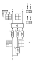
- FIG. 1 illustrates a configuration of a system using an image processing device.
- the system 10 has a polarized light imaging unit 20 and an image processing unit 30.
- the polarized light imaging unit 20 is arranged with unpolarized pixels and polarized pixels provided in at least two polarization directions, and generates an image signal of the captured image and outputs it to the image processing unit 30.
- FIG. 2 illustrates the configuration of the polarized light imaging unit.
- the polarized light imaging unit 20 has a configuration in which a polarizing filter 22 is arranged on an incident surface of an image sensor 21 such as a CMOS (Complementary Metal Oxide Semiconductor) or a CCD (Charge Coupled Device).
- CMOS Complementary Metal Oxide Semiconductor
- CCD Charge Coupled Device
- FIG. 3 illustrates the configuration of the image sensor.
- the image sensor 21 includes a pixel array unit 211 in which a plurality of pixels are arranged in an array, for example, a two-dimensional matrix, a vertical scanning circuit 212 and a horizontal scanning circuit 213 that control the drive of the pixel array unit 211. ing.
- the pixel array unit 211 shows only a part of the pixels in the row direction and the column direction.
- the pixels of the pixel array unit 211 have a photodiode and a transistor for charge transfer and reset, although not shown. Each pixel is connected to the vertical scanning circuit 212 via a reset line and a selection line, and is connected to the horizontal scanning circuit 213 via a signal line.
- the vertical scanning circuit 212 outputs a reset signal to a pixel reset transistor via a reset line to discharge accumulated charges. After that, the vertical scanning circuit 212 outputs the read signal to the charge transfer transistors of the polarized pixel and the unpolarized pixel via the selection line, and the exposure period from the output of the reset signal to the output of the read signal. The electric charge accumulated in the signal is output to the signal line as a signal current.
- the horizontal scanning circuit 213 performs a process of converting the signal current read from each pixel into a digital pixel signal, a gain adjustment process of the pixel signal, and the like, and the processed pixel signal is image processing unit 30 in the order of pixels in the horizontal direction. Output to. Further, the vertical scanning circuit 212 and the horizontal scanning circuit 213 perform the above-mentioned processing for each line.
- FIG. 4 illustrates the pixel configuration of the polarizing filter.
- the polarizing filter 22 is composed of unpolarized pixels and polarized pixels in at least two polarization directions, and a photonic liquid crystal, a wire grid, or the like is used as the polarized pixels.
- FIG. 4A illustrates a case where the polarizing filter 22 is composed of unpolarized pixels and three polarized pixels having different polarization directions.
- the polarizing filter 22 is composed of, for example, a 2 ⁇ 2 pixel region as a polarized pixel block, and the polarized pixel block is composed of one unpolarized pixel and three polarized pixels having polarization directions of “0 °, 90 °, 135 °”.
- the polarized pixel block is repeatedly provided in the horizontal direction and the vertical direction.
- FIG. 4B illustrates a case where the polarizing filter 22 is composed of an unpolarized pixel and two polarized pixels having different polarization directions.
- the polarizing filter 22 is composed of, for example, a 2 ⁇ 2 pixel region as a polarized pixel block, and the polarized pixel block is composed of two unpolarized pixels and two polarized pixels having polarization directions of “90 ° and 135 °”. Polarized pixel blocks are repeatedly provided in the horizontal and vertical directions.
- the polarized image pickup unit 20 configured in this way generates an image signal of an image captured image composed of polarized pixels and unpolarized pixels by sequentially reading out pixel signals, and outputs the image signal to the image processing unit 30. Further, the polarized light imaging unit 20 may control the reset timing of the unpolarized pixel and set the exposure period of the unpolarized pixel so that the unpolarized pixel becomes equal to the sensitivity of the polarized pixel.
- the image processing unit 30 has a demosaic processing unit 31, an invalid pixel detection unit 32, and a polarization information generation unit 33.
- the demosaic processing unit 31 may be provided in the polarized light imaging unit 20.
- the demosaic processing unit 31 generates an unpolarized image and a polarized image for each polarization direction from the captured image acquired by the polarized light imaging unit 20.
- the demosaic processing unit 31 includes polarized pixels at pixel positions in the same polarization direction in the pixels of interest and peripheral pixels of the pixels of interest in the captured image acquired by the polarized imaging unit 20, pixel positions equal to the polarized pixels, and pixel positions of the pixels of interest.
- the pixel value of the polarized pixel at the pixel position of the pixel of interest is calculated for each polarization direction using the non-polarized pixel of.
- the demosaic processing unit 31 considers that there is a positive correlation between the unpolarized pixel and the polarized pixel, and generates a high-resolution polarized image by supplementing the high-frequency component lost in the polarized image from the unpolarized image. To do.
- the demosaic processing unit uses the relationship between the pixel average value of the unpolarized pixel at the pixel position in the same polarization direction and the pixel value of the unpolarized pixel at the pixel position of the pixel of interest, and the pixel position at the same polarization direction.
- the pixel value of the polarized pixel at the pixel position of the pixel of interest with respect to the pixel average value of the polarized pixel is calculated.
- FIG. 5 illustrates the configuration of the demosaic processing unit.
- the demosaic processing unit 31 includes an unpolarized pixel interpolation unit 310 for generating an unpolarized image, a polarized pixel averaging processing unit 311 for generating a high-resolution polarized image using the unpolarized image, and an unpolarized pixel. It has an averaging processing unit 312, a central pixel acquisition unit 313, and a correlation processing unit 314.
- the non-polarized pixel interpolation unit 310 interpolates the pixel values at the pixel positions where the pixel values of the unpolarized pixels are not obtained in the captured image acquired by the polarized image pickup unit 20 by using the pixel values of the peripheral unpolarized pixels.
- a non-polarized image is generated by calculating by processing or the like.
- the non-polarized pixel interpolation unit 310 outputs the generated non-polarized image to the non-polarized pixel averaging processing unit 312 and the center pixel acquisition unit 313.
- the polarized pixel averaging processing unit 311 calculates the pixel average value for the pixel of interest for each polarization direction using the pixel of interest and the peripheral pixels located around the pixel of interest, and outputs the pixel average value to the correlation processing unit 314.
- the non-polarized pixel averaging processing unit 312 uses the attention pixel and peripheral pixels located around the attention pixel, and has the same pixel position as when the polarized pixel averaging processing unit 311 calculates the pixel average value for each polarization direction.
- the pixel average value is calculated from the pixels and output to the correlation processing unit 314.
- the central pixel acquisition unit 313 extracts the pixel value of the pixel of interest from the unpolarized image and outputs it to the correlation processing unit 314.
- the correlation processing unit 314 has a pixel average value for each polarization direction calculated by the polarized pixel averaging processing unit 311 and a pixel average value calculated by the unpolarized pixel averaging processing unit 312 corresponding to the pixel average value for each polarization direction. Then, the pixel value for each polarization direction of the pixel of interest is calculated from the pixel value of the pixel of interest extracted by the center pixel acquisition unit 313.
- the demosaic process of polarized pixels will be described with reference to FIG. FIG. 6A shows a polarized image, and FIG. 6B shows a non-polarized image.
- the polarized pixel averaging processing unit 311 has a pixel position of interest "x, y" and peripheral pixel positions "x-1, y-1", “x, y-1", “x + 1, y-1” and "x + 1, y-1” in the polarized image. Calculate the pixel average value for each polarization direction using the pixels of "x-1, y", “x + 1, y”, “x-1, y + 1", "x, y + 1", and "x + 1, y + 1". ..
- the pixel value of the pixel position of interest in the polarized image is "P (x, y)", and the pixel value of the peripheral pixel position is "P (x-1, y-1)" "P (x, y-1)”.
- P (x + 1, y-1) "P (x-1, y)”
- P (x + 1, y) "P (x + 1, y)”
- P (x-1, y + 1) P (x-1, y + 1)
- P (x, y) y + 1)
- the pixel value of the pixel position of interest in the unpolarized image is "Q (x, y)", and the pixel value of the peripheral pixel position is "Q (x-1, y-1)" "Q (x, y-1)”.
- Q (x + 1, y-1) "Q (x-1, y)”
- Q (x + 1, y) "Q (x + 1, y)”
- Q (x-1, y + 1) Q (x-1, y + 1)
- Q (x, y) y + 1) and“ Q (x + 1, y + 1) ”.
- mP0 (x, y) P (x, y) ⁇ ⁇ ⁇ (1)
- mP1 (x, y) (P (x-1, y-1) + P (x + 1, y-1) + P (x-1, y + 1) + P (x + 1, y + 1)) / 4 ⁇ ⁇ ⁇ (2)
- mP2 (x, y) (P (x, y-1) + P (x, y + 1)) / 2 ...
- the unpolarized pixel averaging processing unit 312 calculates the pixel average value from the pixel value at the pixel position equal to the case of calculating the pixel average value for each polarization direction by using the attention pixel and the peripheral pixels of the attention pixel in the unpolarized image. To do.
- mQ0 (x, y) Q (x, y) ⁇ ⁇ ⁇ (4)
- mQ1 (x, y) (Q (x-1, y-1) + Q (x + 1, y-1) + Q (x-1, y + 1) + Q (x + 1, y + 1)) / 4 ⁇ ⁇ ⁇ (5)
- mQ2 (x, y) (Q (x, y-1) + Q (x, y + 1)) / 2 ... (6)
- the correlation processing unit 314 considers that there is a positive correlation between the polarized pixel and the unpolarized pixel, and determines that the pixel average value calculated from the polarized image, the pixel average value calculated from the unpolarized image, and the pixel of interest in the unpolarized image. From the value, the pixel value for each polarization direction of the pixel position of interest is calculated.
- the correlation processing unit 314 outputs the pixel value Q (x, y) as the pixel value of the pixel of interest in the unpolarized image.
- P0 (x, y) mP0 (x, y) ⁇ Q (x, y) / mQ0 (x, y) ⁇ ⁇ ⁇ (7)
- P1 (x, y) mP1 (x, y) ⁇ Q (x, y) / mQ1 (x, y) ⁇ ⁇ ⁇ (8)
- P2 (x, y) mP2 (x, y) ⁇ Q (x, y) / mQ2 (x, y) ⁇ ⁇ ⁇ (9)
- the demosaic processing unit 31 generates a polarized image for each polarization direction by performing the above processing with each pixel of the polarized image as a pixel of interest. Further, since the signal component of the unpolarized pixel is normalized by the pixel average value and superimposed on the polarized pixel, the demosaic processing unit 31 can improve the problem such as folding back caused by the frequency limit of the polarized pixel. This makes it possible to generate a polarized image having the same resolution as an unpolarized image for each polarization direction.
- the pixel array corresponds to the Bayer array, for example, the document "B. Gunturk, J. Grotzbach, Y. Altumbasak, R. scaffer, and R.
- demosaic processing unit 31 only needs to be able to generate an unpolarized image and a polarized image for each polarization direction, and the demosaic processing is not limited to the above method.
- the invalid pixel detection unit 32 detects an invalid pixel by comparing a preset threshold value with the pixel values of the unpolarized pixel and the polarized pixel.
- a saturation detection threshold value Th for detecting saturated pixels and a black crushing detection threshold Thb for detecting black crushed pixels are set.
- the invalid pixel detection unit 32 compares the pixel value of each pixel with the saturation detection threshold value Th, and sets a pixel having a pixel value larger than the saturation detection threshold value The as an invalid pixel. Further, the invalid pixel detection unit 32 compares the pixel value of each pixel with the black crush detection threshold Thb, and sets a pixel having a pixel value smaller than the black crush detection threshold Thb as an invalid pixel.
- the unpolarized pixel is not provided with a polarizing filter and the amount of incident light is larger (higher sensitivity) than the polarized pixel, and the polarized pixel is reduced in the amount of light by the polarizing filter and the amount of incident light is larger than that of the polarized pixel.
- the saturation detection threshold value Th and the blackout detection threshold value Thb are the level difference between the specified level and the threshold value, for example, the level difference between the maximum output level of the polarization imaging unit 20 and the saturation detection threshold value The, and the minimum output level of the polarization imaging unit 20.
- the level difference from the blackout detection threshold Thb may be set to be equal, or the threshold may be set individually according to the characteristics of the polarized light imaging unit 20.
- the image pickup device 21 is known to generate shot noise depending on the amount of signal charge, and the shot noise is proportional to the square root of the amount of signal charge.
- the black crush detection threshold Thb is set to be larger than the output minimum value of the polarized light imaging unit 20 only at the first level
- the saturation detection threshold Th is the output maximum value of the polarized light imaging unit 20 only at the second level smaller than the first level. Set smaller than. In this way, if the saturation detection threshold Th and the black crush detection threshold Thb are set, the influence of noise at the time of detecting the invalid pixel with black crush becomes larger than that at the time of detecting the invalid pixel with saturation. You can prevent that.
- the saturation detection threshold value Th and the blackout detection threshold value Thb may be set according to the optical characteristics of the polarizing filter 22.
- the transmittance of the polarizing filter 22 when the transmittance of the polarizing filter 22 is low, the amount of light incident on the image sensor 21 is small, so that the signal level of the pixel signal is small. Further, when the level of the pixel signal is adjusted, the gain becomes high, and the influence of noise may become larger than when the transmittance is high. Therefore, the level difference between the specified level and the threshold value may be larger when the transmittance of the polarizing filter 22 is low than when the transmittance is high.
- the invalid pixel detection unit 32 compares the saturation detection threshold value Tha, the blackout detection threshold value Thb ( ⁇ Tha), and the pixel value I (x, ⁇ ) of the pixel x, and I (x, ⁇ )> Tha or Thb> I.
- the pixel x is set as an invalid pixel.
- "x" is a pixel index.
- the invalid pixel detection unit 32 outputs an invalid flag V (x, ⁇ ) indicating an invalid pixel detection result to the polarization information generation unit 33.
- the polarization information generation unit 33 performs polarization information generation processing based on the unpolarized image generated by the demosaic processing unit 31 and the polarized image for each polarization direction, and polarizes according to the detection result of the invalid pixel in the invalid pixel detection unit 32. Switch the information generation process.
- the polarization state of the subject can be expressed as, for example, the polarization model equation shown in the equation (10).
- the parameters S 0 , S 1 , and S 2 are Stokes parameters
- the Stokes parameter S 0 is the sum of the observed brightness of 0 ° polarized light and the observed brightness of 90 ° polarized light, and indicates the intensity. It is a parameter.
- the Stokes parameter S 1 is a parameter showing the difference between the observed brightness of 0 ° polarized light and the observed brightness of 90 ° polarized light
- the Stokes parameter S 2 is a parameter showing the difference between the observed brightness of 45 ° polarized light and the observed brightness of 135 ° polarized light.
- the polarization information generation unit 33 uses the pixel values of the unpolarized image and the polarized image for each polarization direction to fit to the polarization model equation shown in the equation (10), calculates the Stokes parameter, and shows the calculated Stokes parameter. Generates and outputs polarization information. Further, the polarization information generation unit 33 switches the polarization information generation process, that is, the Stokes parameter calculation method, based on the invalidity flag V (x, ⁇ ) from the invalid pixel detection unit 32 in the fitting to the polarization model formula. , The Stokes parameters S 0 , S 1 , S 2 in the polarization model equation of the equation (10) are calculated by, for example, the minimum square method or the like, using the pixel values of the pixels that are not determined to be invalid pixels.
- a 2 ⁇ 2 polarized pixel block has three polarized pixels (pixels having polarization directions of “0 °”, “90 °”, and “135 °”) and one unpolarized pixel. It is composed of pixels.
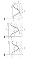
- FIG. 7 illustrates the relationship between the brightness of the unpolarized pixel, the brightness of the polarized pixel, and the angle in the polarization direction (No. 1).
- FIG. 7A illustrates a case where not all the pixels in the polarized pixel block are determined to be invalid pixels.
- the Stokes parameter S 0 is calculated based on the equation (11).
- the coefficient K in the equation (11) is a coefficient that absorbs the sensitivity difference between the polarized pixel and the unpolarized pixel.
- the polarization information generating unit 33 the pixel value I (x, 0), I (x, 90), the Stokes parameters by the least square method using the I (x, 135) and Stokes parameters S 0 S 2, S 1 is calculated.
- FIG. 7B illustrates a case where only unpolarized pixels are determined to be invalid pixels.
- V (x, 135) 0
- the Stokes parameter is calculated without using unpolarized pixels.
- the polarization information generation unit 33 uses the pixel values I (x, 0), I (x, 90), I (x, 135) of polarized pixels that are not invalid pixels and the least squares method from the polarization model equation shown in equation (10).
- the Stokes parameters S 2 , S 1 , and S 0 are calculated by such means.
- FIG. 7C illustrates a case where only one polarized pixel in the polarized pixel block is determined to be an invalid pixel.
- the polarization information generating unit 33 calculates the Stokes parameters S 2, S 1 by the least square method using the I (x, 90) and the Stokes parameters S 0.
- the polarization information generation unit 33 cannot calculate the Stokes parameters S 2 , S 1 , and S 0 when the two polarization pixels in the three polarization pixels of the polarization pixel block are invalid pixels. In this case, the polarization information generation unit 33 may use information indicating that the polarization characteristic cannot be acquired as the polarization information.
- a 2 ⁇ 2 pixel polarized pixel block is composed of two polarized pixels (pixels having polarization directions of “90 °” and “135 °”) and two non-polarized pixels.
- FIG. 8 illustrates the relationship between the brightness of the unpolarized pixel, the brightness of the polarized pixel, and the angle in the polarization direction (No. 2).
- FIG. 8A illustrates a case where not all the pixels in the polarized pixel block are determined to be invalid pixels.
- the Stokes parameter S 0 is calculated based on the equation (11).
- the invalid flag V (x, -1a) indicates the detection result of one unpolarized pixel in the two unpolarized pixels
- the invalid flag V (x, -1b) indicates the detection result of one unpolarized pixel in the two unpolarized pixels. The detection result of the unpolarized pixel of is shown.
- the polarization information generation unit 33 calculates the Stokes parameters S 2 and S 1 by the least squares method or the like using the pixel values I (x, 90), I (x, 135) and the Stokes parameter S 0.
- FIG. 8B illustrates a case where only one unpolarized pixel is determined to be an invalid pixel.
- the pixel used for calculating the Stokes parameter is one unpolarized pixel in the pixel configuration shown in FIG. 4A, as in the case where only one polarized pixel in the polarized pixel block is determined to be an invalid pixel.
- the polarization information generation unit 33 cannot calculate the Stokes parameters S 2 , S 1 , S 0 when it is determined that two unpolarized pixels or one polarized pixel in the polarized pixel block is an invalid pixel.
- FIG. 8C illustrates a case where one polarized pixel in the polarized pixel block is determined to be an invalid pixel.
- the polarization information generation unit 33 may use information indicating that the polarization characteristic cannot be acquired as the polarization information.
- FIG. 9 is a flowchart showing the operation of the image processing unit.
- the image processing unit acquires the captured image.
- the image processing unit generates an image captured by using a polarized image capturing unit composed of polarized pixels and non-polarized pixels, and proceeds to step ST2.
- step ST2 the image processing unit generates a polarized image and a non-polarized image for each polarization direction.
- the image processing unit performs demosaic processing using the captured image, generates a polarized image and a non-polarized image for each polarization direction, and proceeds to step ST3.
- step ST3 the image processing unit detects invalid pixels.
- the image processing unit compares the preset saturation detection threshold Tha, the blackout detection threshold Thb, and the pixel values of the unpolarized pixel and the polarized pixel, and the pixel having a pixel value larger than the saturation detection threshold Tha and the blackout detection threshold.
- a pixel having a pixel value smaller than Thb is detected as an invalid pixel, and the process proceeds to step ST4.
- step ST4 the image processing unit generates polarization information. Based on the pixel value for each polarization direction, the unpolarized pixel value, and the invalid pixel detection result, the image processing unit performs fitting to the polarization model formula using the pixel values of the polarized pixel and the non-polarized pixel that are not invalid pixels. For example, the Stokes parameter is calculated. The image processing unit generates polarization information indicating the calculated Stokes parameter.
- the image processing unit demomosaizes the unpolarized image and the polarized image for each polarization direction from the captured image generated by the polarization imaging unit 20 in which the unpolarized pixel and at least two polarized pixels for each polarization direction are arranged. Generated by the processing unit 31. Further, the image processing unit generates polarization information indicating the polarization characteristics of the subject included in the captured image from the unpolarized image and the polarized image generated by the demosaic processing unit 31 in the polarization information generation unit 33.
- the image processing unit detects invalid pixels from the unpolarized image and the polarized image, and generates polarized information without using the invalid pixels, so that the correct polarized information can be acquired.
- the polarization angles of the polarized pixels are "0 °, 90 °, 135 °" is illustrated, but the polarization angles may be configured not to be orthogonal angles.
- the polarized pixel block may be composed of one unpolarized pixel and three polarized pixels having polarization angles of “0 °, 60 °, 120 °”.
- the polarization information generation unit 33 calculates the Stokes parameter as the polarization information, but the polarization information is not limited to the case where the Stokes parameter is indicated.
- the polarization information generation unit 33 may generate normal information as polarization information.
- the polarization information generation unit 33 calculates the azimuth angle ⁇ based on, for example, the equation (13).
- the polarization information generation unit 33 calculates the zenith angle ⁇ based on the equation (14).
- the parameters A, B, C, and D in the equation (14) are values calculated by the equations (15) to (18), and the degree of polarization ⁇ shown in the equations (15) and (16) is the equation (15). Calculate based on 19). Further, in the equations (15), (17) and (18), the parameters A, B, C and D are calculated using the refractive index n of the subject OB.
- the polarized light imaging unit 20 may generate polarized light information based on the color captured image so that the polarized light imaging unit 20 generates a color captured image.
- FIG. 10 illustrates the configuration of a polarized light imaging unit that generates a color captured image.
- a color mosaic filter 23 is provided on the incident surface of the image sensor 21.
- the color mosaic filter 23 is not limited to the case where it is provided between the image pickup device 21 and the polarizing filter 22, and may be provided on the incident surface of the polarizing filter 22.
- the polarizing filter 22 and the color mosaic filter 23 are configured to provide pixels in each polarization direction with the same color so that the polarization pixels in different polarization directions are not affected by the difference in color. Further, the polarizing filter 22 and the color mosaic filter 23 are configured so that the pixel values of unpolarized pixels can be obtained for each color.
- FIG. 11 illustrates the relationship between the color mosaic filter and the polarizing filter (two polarization directions).
- the polarizing filter 22 has a configuration in which two polarized pixels and two non-polarized pixels having different polarization directions are received in a 2 ⁇ 2 pixel region.
- the color mosaic filter 23 has a configuration in which the 2 ⁇ 2 pixel area is a red (R), green (G), and blue (B) color unit, and the 4 ⁇ 4 pixel area is a red 2 ⁇ 2 pixel area.
- the polarization imaging unit 20 generates pixel values of polarized pixels for each of the two polarization directions and pixel values of unpolarized pixels of either red, green, or blue for each 2 ⁇ 2 pixel region.
- the color mosaic filter 23 has a configuration in which a 2 ⁇ 2 pixel region is set as a color unit of red (R), green (G), and blue (B).
- the polarization filter 22 has a configuration in which two polarized pixels and two unpolarized pixels having different polarization directions are received in a green 2 ⁇ 2 pixel region, and the 4 ⁇ 4 pixel region is a red 2 ⁇ 2 pixel region.
- the polarization imaging unit 20 generates pixel values of unpolarized pixels of either red, green, or blue color and pixel values of polarized pixels in the two polarization directions in green for each 2 ⁇ 2 pixel region. Will be done.
- the polarizing filter 22 has a configuration in which two polarized pixels and two non-polarized pixels having different polarization directions are received in a 2 ⁇ 2 pixel region.
- the color mosaic filter 23 has a configuration in which the 2 ⁇ 2 pixel area is composed of three green (G) pixels and one red (R) or blue (B) pixel, and the 4 ⁇ 4 pixel area is a red pixel. There are two 2 ⁇ 2 pixel areas including, and two 2 ⁇ 2 pixel areas including blue pixels.
- the pixel values of the unpolarized pixels which are green pixels and red pixels or green pixels and blue pixels, and the pixels of the polarized pixels in each of the two polarization directions in green, for each 2 ⁇ 2 pixel region. A value is generated.
- the color mosaic filter 23 covers a 2 ⁇ 2 pixel area with two white (W) pixels and two pixels of any color of red (R), green (G), or blue (B).
- the configuration is as follows.
- the 4x4 pixel area is a 2x2 pixel area including a red pixel, a 2x2 pixel area including a blue pixel, and two 2x2 pixel areas including a green pixel.
- the polarizing filter 22 has a configuration in which white pixels in a 2 ⁇ 2 pixel region including green pixels are polarized pixels having the same polarization direction, and two polarizing pixels in each of the two polarization directions are provided in the 4 ⁇ 4 pixel region. To do.
- the pixel value of the polarized pixel in any of the polarization directions in is generated.
- the color mosaic filter 23 has two white (W) pixels and green (G) and red (R), or two white (W) pixels and green (G) in a 2 ⁇ 2 pixel region. ) And blue (B) pixels.
- the 4x4 pixel area is defined as two 2x2 pixel areas including red pixels and two 2x2 pixel areas including blue pixels.
- the polarizing filter 22 has a configuration in which one white pixel in the 2 ⁇ 2 pixel region is a polarizing pixel, and the 4 ⁇ 4 pixel region is provided with two polarizing pixels in each of the two polarization directions.
- the pixel values of green and red or green and blue unpolarized pixels and the pixel values of polarized pixels in any of the two polarization directions are set for each 2 ⁇ 2 pixel region. Will be generated.
- pixel values of unpolarized pixels of each color and pixel values of polarized pixels for each polarization direction are generated for each 4 ⁇ 4 pixel region.
- FIG. 12 illustrates the relationship between the color mosaic filter and the polarizing filter (three polarization directions).
- the color mosaic filter 23 covers a 2 ⁇ 2 pixel area with two white (W) pixels and two pixels of any color of red (R), green (G), or blue (B).
- the configuration is as follows.
- the 4x4 pixel area is a 2x2 pixel area including a red pixel, a 2x2 pixel area including a blue pixel, and two 2x2 pixel areas including a green pixel.
- the polarizing filter 22 has a configuration in which white pixels in a 2 ⁇ 2 pixel region are used as polarizing pixels in any of the polarization directions, and two polarizing pixels in each of the four polarization directions are provided in the 4 ⁇ 4 pixel region.
- the pixel value of the unpolarized pixel of either red, green, or blue color and the polarized pixel in any of the four polarization directions are used for each 2 ⁇ 2 pixel region. Pixel value is generated.
- the color mosaic filter 23 covers a 2 ⁇ 2 pixel area with two white (W) pixels and green (G) and red (R) or two white (W) pixels and green (G). And blue (B) pixels.
- the 4x4 pixel area is defined as two 2x2 pixel areas including red pixels and two 2x2 pixel areas including blue pixels.
- the polarizing filter 22 has a configuration in which two white pixels in the 2 ⁇ 2 pixel region are polarized pixels having different polarization directions, and in the 4 ⁇ 4 pixel region, two polarizing pixels in each of the four polarization directions are provided.
- the polarized light imaging unit 20 generates pixel values of green and red or green and blue unpolarized pixels and pixel values of polarized pixels in the two polarization directions for each 2 ⁇ 2 pixel region.
- the pixel values of green and red or green and blue unpolarized pixels and the pixel values of polarized pixels in any two of the four polarization directions are used for each 2 ⁇ 2 pixel region. Is generated.
- the color mosaic filter 23 has a configuration in which the 2 ⁇ 2 pixel region is a red (R), green (G), and blue (B) color unit, and the 4 ⁇ 4 pixel region is red. 2 ⁇ 2 pixel area, blue 2 ⁇ 2 pixel area, and green 2 ⁇ 2 pixel area.
- the polarizing filter 22 has a configuration in which four polarizing pixels having different polarization directions are provided in a green 2 ⁇ 2 pixel region. In this case, in the polarized image pickup unit 20, the pixel value of the unpolarized pixel is generated in the red or blue 2 ⁇ 2 pixel region, and the pixel value of the polarized pixel in each polarization direction is generated in the green 2 ⁇ 2 pixel region. Will be done.
- the polarized light imaging unit 20 generates pixel values of unpolarized pixels of each color and pixel values of polarized pixels for each polarization direction for each 4 ⁇ 4 pixel region.
- the demosaic processing unit 31 When the polarized image pickup unit 20 generates a color captured image, the demosaic processing unit 31 generates a non-polarized image for each color component from the color image. Further, the demosaic processing unit 31 generates a polarized image for each polarization direction.
- the polarization information generation unit 33 generates polarization information using a polarized image or a non-polarized image generated by the demosaic processing unit 31. Since the polarized pixels are white or the same color as described above, there is no influence due to the difference in color between the polarized pixels. Therefore, the polarization information can be correctly generated even if the color captured image is used. In addition, in FIG.
- the sensitivity of the green pixel is lower than that of the red pixel and the blue pixel which are non-polarized pixels. Therefore, if the pixel value of the green pixel is corrected according to the decrease in sensitivity of the polarized pixel, the conventional Bayer array demosaic process is performed, which is the same as the case where the pixel of each color component is a non-polarized pixel. A color component image can be generated.
- the image processing unit 30 can generate a non-polarized image for each color by performing integrated processing using pixels of the same color.
- the configuration of the image processing unit is not limited to the configuration shown in FIG.
- the image processing unit 30 is configured corresponding to the pixel configuration of the polarized light imaging unit 20 as described above, the polarized light imaging unit 20 and the image processing unit 30 may be integrally configured.
- the technology according to the present disclosure can be applied to various products.
- the technology according to the present disclosure includes any type of movement such as automobiles, electric vehicles, hybrid electric vehicles, motorcycles, bicycles, personal mobility, airplanes, drones, ships, robots, construction machines, agricultural machines (tractors), and the like. It may be realized as a device mounted on the body. If applied to such a field, accurate polarization information can be acquired, so that the surrounding environment can be accurately grasped in three dimensions based on, for example, polarization information, and fatigue of the driver or operator can be reduced. .. In addition, automatic driving and the like can be performed more safely.
- the technology according to this disclosure can also be applied to the medical field. For example, if it is applied when the captured image of the surgical site is used when performing surgery, it becomes possible to accurately obtain an image without reflection and the three-dimensional shape of the surgical site, which reduces the operator's fatigue and is safe and safe. It becomes possible to perform surgery more reliably.
- the technology related to this disclosure can also be applied to fields such as public services. For example, when an image of a subject is published in a book, a magazine, or the like, unnecessary reflection components or the like can be accurately removed from the image of the subject.
- the series of processes described in the specification can be executed by hardware, software, or a composite configuration of both.
- the program that records the processing sequence is installed in the memory in the computer embedded in the dedicated hardware and executed.
- the program can be installed and executed on a general-purpose computer capable of executing various processes.
- the program can be recorded in advance on a hard disk as a recording medium, an SSD (Solid State Drive), or a ROM (Read Only Memory).
- the program is a flexible disc, CD-ROM (Compact Disc Read Only Memory), MO (Magneto optical) disc, DVD (Digital Versatile Disc), BD (Blu-Ray Disc (registered trademark)), magnetic disc, semiconductor memory card. It can be temporarily or permanently stored (recorded) on a removable recording medium such as an optical disc.
- a removable recording medium can be provided as so-called package software.
- the program may be transferred from the download site to the computer wirelessly or by wire via a network such as a LAN (Local Area Network) or the Internet.
- the computer can receive the program transferred in this way and install it on a recording medium such as a built-in hard disk.
- the image processing device of the present technology can have the following configurations.
- An invalid pixel detection unit that detects saturated pixels and blackened pixels as invalid pixels from an unpolarized image obtained by imaging using a polarized light imaging unit and a plurality of polarized images having different polarization directions.
- An image processing apparatus including a polarization information generating unit that performs polarization information generation processing based on the unpolarized image and the polarized image and switches the polarization information generation processing according to the detection result of the invalid pixel in the invalid pixel detection unit. ..
- the polarization information generation unit includes the pixel of the unpolarized image and other polarized light that is not detected as an invalid pixel.
- the image processing apparatus according to (1) which generates the polarization information using the pixels of the image.
- the plurality of polarized images are three or more polarized images having different polarization directions.
- the image processing apparatus according to (3) wherein the polarization information generation unit generates the polarization information by using the pixels of the unpolarized image and the pixels of at least two or more polarized images that are not detected as invalid pixels.
- the image processing apparatus wherein the at least two or more polarized images are polarized images whose polarization directions are not orthogonal to each other.
- the polarization information generation unit When the invalid pixel is not detected, the polarization information generation unit generates the polarization information using the pixel of the unpolarized image and the pixel of the polarized image, whichever is (1) to (5). Image processing device described in polarized light.
- the invalid pixel detection unit detects the saturated pixel from the unpolarized image and the blackened pixel from the polarized image as the invalid pixel.
- the invalid pixel detection unit detects a pixel having a pixel value larger than a preset saturation detection threshold value as the saturated pixel, and the invalid pixel detection unit detects a pixel having a pixel value smaller than a preset blackout detection threshold value.
- the image processing apparatus according to any one of (1) to (7), which detects as blackened pixels.
- the blackout detection threshold value is set to be larger than the minimum output value of the polarization imaging unit by the first level, and the saturation detection threshold value is the output of the polarization imaging unit by the second level smaller than the first level.
Landscapes
- Engineering & Computer Science (AREA)
- Multimedia (AREA)
- Signal Processing (AREA)
- Physics & Mathematics (AREA)
- Spectroscopy & Molecular Physics (AREA)
- Studio Devices (AREA)
- Color Television Image Signal Generators (AREA)
Abstract
無効画素検出部32は、偏光撮像部20を用いて撮像を行うことにより得られた無偏光画像と偏光方向の異なる複数の偏光画像から無効画素を検出する。例えば、無効画素検出部32は、無偏光画像から予め設定された飽和検出閾値よりも画素値が大きい飽和画素と、予め設定された黒潰れ検出閾値よりも画素値が小さい黒潰れ画素を無効画素として検出する。偏光情報生成部33は、無偏光画像と偏光画像に基づき偏光情報の生成処理を行い、無効画素検出部32における無効画素の検出結果に応じて偏光情報の生成処理を切り替えて、無効画素を用いることなく偏光情報を生成することで。正しい偏光情報を取得できるようになる。
Description
この技術は、画像処理装置と画像処理方法および撮像装置に関し、精度の良好な偏光情報を取得できるようにする。
従来、偏光撮像部と偏光フィルタを用いて偏光画像を取得する方法が開示されている。例えば、特許文献1では、撮像素子の前にパターン化偏光子とカラーモザイクフィルタを配置して被写体の撮像を行い、得られた偏光画像に基づいてカラー情報と偏光情報を取得する方法が開示されている。また、特許文献2では、偏光成分を示す偏光画像だけでなく光量の低下を生じていない無偏光画像を用いることで、偏光画像に基づいて偏光情報を生成する場合に比べて精度のよい偏光情報を取得することが開示させている。
ところで、無偏光画素を用いることで精度のよい偏光情報を取得するためには、2つの無偏光画素と2つの偏光画素のいずれも有効な画素値を保持している必要があり、無偏光画素の飽和や偏光画素の黒潰れを生じると取得された偏光情報に誤りが含まれてしまうおそれがある。
そこで、この技術では、正しい偏光情報を取得できる画像処理装置と画像処理方法および撮像装置を提供する。
この技術の第1の側面は、
偏光撮像部を用いて撮像を行うことにより得られた無偏光画像と偏光方向の異なる複数の偏光画像から飽和画素と黒潰れ画素を無効画素として検出する無効画素検出部と、
前記無偏光画像と前記偏光画像に基づき偏光情報の生成処理を行い、前記無効画素検出部における前記無効画素の検出結果に応じて前記偏光情報の生成処理を切り替える偏光情報生成部
を備える画像処理装置にある。
偏光撮像部を用いて撮像を行うことにより得られた無偏光画像と偏光方向の異なる複数の偏光画像から飽和画素と黒潰れ画素を無効画素として検出する無効画素検出部と、
前記無偏光画像と前記偏光画像に基づき偏光情報の生成処理を行い、前記無効画素検出部における前記無効画素の検出結果に応じて前記偏光情報の生成処理を切り替える偏光情報生成部
を備える画像処理装置にある。
この技術において、無効画素検出部は、偏光撮像部を用いて撮像を行うことにより得られた無偏光画像と偏光方向の異なる複数の偏光画像から無効画素を検出する。例えば、無効画素検出部は、無偏光画像から予め設定された飽和検出閾値よりも画素値が大きい飽和画素と、予め設定された黒潰れ検出閾値よりも画素値が小さい黒潰れ画素を無効画素として検出する。飽和検出閾値と黒潰れ検出閾値は、偏光撮像部で撮像を行うことにより取得される画像の特性に応じて設定してもよい。例えば、黒潰れ検出閾値は第1レベルだけ偏光撮像部の出力最小値よりも大きく設定して、飽和検出閾値は第1レベルよりも小さい第2レベルだけ偏光撮像部の出力最大値よりも小さく設定する。
偏光情報生成部は、無偏光画像と偏光画像に基づき偏光情報の生成処理を行い、無効画素検出部における無効画素の検出結果に応じて偏光情報の生成処理を切り替える。例えば、偏光情報生成部は、無偏光画像の画素が無効画素として検出されている場合、無偏光画像の画素と無効画素として検出されていない少なくとも偏光方向が直交していない2以上の偏光画像の画素を用いて偏光情報を生成する。複数の偏光画像は、偏光方向の異なる3以上の偏光画像であり、偏光情報生成部は、無偏光画像の画素と無効画素として検出されていない少なくとも2以上の偏光画像の画素を用いて偏光情報を生成する。また、偏光情報生成部は、無効画素が検出されていない場合、無偏光画像の画素と偏光画像の画素を用いて偏光情報を生成する。
この技術の第2の側面は、
偏光撮像部を用いて撮像を行うことにより得られた無偏光画像と偏光方向の異なる複数の偏光画像から飽和画素と黒潰れ画素を無効画素として無効画素検出部で検出することと、
偏光情報生成部で前記無偏光画像と前記偏光画像に基づき偏光情報の生成処理を行い、前記無効画素検出部における前記無効画素の検出結果に応じて前記偏光情報の生成処理を切り替えること
ことを含む画像処理方法にある。
偏光撮像部を用いて撮像を行うことにより得られた無偏光画像と偏光方向の異なる複数の偏光画像から飽和画素と黒潰れ画素を無効画素として無効画素検出部で検出することと、
偏光情報生成部で前記無偏光画像と前記偏光画像に基づき偏光情報の生成処理を行い、前記無効画素検出部における前記無効画素の検出結果に応じて前記偏光情報の生成処理を切り替えること
ことを含む画像処理方法にある。
この技術の第3の側面は、
偏光情報の生成をコンピュータで実行させるプログラムであって、
偏光撮像部を用いて撮像を行うことにより得られた無偏光画像と偏光方向の異なる複数の偏光画像から飽和画素と黒潰れ画素を無効画素として検出する手順と、
前記無偏光画像と前記偏光画像に基づき偏光情報の生成処理を行う手順と、
前記無効画素の検出結果に応じて前記偏光情報の生成処理を切り替える手順と
を前記コンピュータで実行させるプログラムにある。
偏光情報の生成をコンピュータで実行させるプログラムであって、
偏光撮像部を用いて撮像を行うことにより得られた無偏光画像と偏光方向の異なる複数の偏光画像から飽和画素と黒潰れ画素を無効画素として検出する手順と、
前記無偏光画像と前記偏光画像に基づき偏光情報の生成処理を行う手順と、
前記無効画素の検出結果に応じて前記偏光情報の生成処理を切り替える手順と
を前記コンピュータで実行させるプログラムにある。
以下、本技術を実施するための形態について説明する。なお、説明は以下の順序で行う。
1.実施の形態の構成と動作
2.他の実施の形態
3.適用例
1.実施の形態の構成と動作
2.他の実施の形態
3.適用例
<1.実施の形態の構成と動作>
図1は、画像処理装置を用いたシステムの構成を例示している。システム10は、偏光撮像部20、画像処理部30を有している。
図1は、画像処理装置を用いたシステムの構成を例示している。システム10は、偏光撮像部20、画像処理部30を有している。
偏光撮像部20は、無偏光画素と少なくとも2つの偏光方向毎に設けた偏光画素が配置されており、撮像画像の画像信号を生成して画像処理部30へ出力する。
図2は、偏光撮像部の構成を例示している。偏光撮像部20は、CMOS(Complementary Metal Oxide Semiconductor)やCCD(Charge Coupled Device)等の撮像素子21の入射面に、偏光フィルタ22を配置した構成とされている。
図3は、撮像素子の構成を例示している。撮像素子21は、複数個の画素がアレイ状、例えば二次元マトリクス状に配列された画素アレイ部211と、画素アレイ部211の駆動制御等を行う垂直走査回路212および水平走査回路213を有している。なお、説明を簡単とするため、画素アレイ部211では、行方向および列方向の一部の画素のみを示している。
画素アレイ部211の画素は、図示せずもフォトダイオードおよび電荷転送用やリセット用のトランジスタを有している。各画素は、リセット線と選択線を介して垂直走査回路212と接続されており、信号線を介して水平走査回路213と接続されている。
垂直走査回路212は、リセット線を介してリセット信号を画素のリセット用のトランジスタへ出力して蓄積電荷を排出させる。その後、垂直走査回路212は、選択線を介して読出信号を偏光画素および無偏光画素の電荷転送用のトランジスタへ出力して、リセット信号が出力されてから読出信号が出力されるまでの露光期間中に蓄積された電荷を信号電流として信号線に出力させる。水平走査回路213は、各画素から読み出された信号電流をデジタルの画素信号に変換する処理や画素信号の利得調整処理等を行い、処理後の画素信号を水平方向の画素順に画像処理部30へ出力する。また、垂直走査回路212と水平走査回路213は、上述の処理をライン毎に行う。
図4は、偏光フィルタの画素構成を例示している。偏光フィルタ22は、無偏光画素と少なくとも2つの偏光方向の偏光画素で構成されており、偏光画素ではフォトニック液晶またはワイヤグリッド等が用いられている。
図4の(a)は、偏光フィルタ22が無偏光画素と偏光方向が異なる3つの偏光画素で構成されている場合を例示している。偏光フィルタ22は、例えば2×2画素領域を偏光画素ブロックとして、偏光画素ブロックは1つの無偏光画素と、偏光方向が「0°,90°,135°」である3つの偏光画素で構成されており、偏光画素ブロックが水平方向および垂直方向に繰り返し設けられている。
図4の(b)は、偏光フィルタ22が無偏光画素と偏光方向が異なる2つの偏光画素で構成されている場合を例示している。偏光フィルタ22は、例えば2×2画素領域を偏光画素ブロックとして、偏光画素ブロックは2つの無偏光画素と、偏光方向が「90°,135°」である2つの偏光画素で構成されており、偏光画素ブロックが水平方向および垂直方向に繰り返し設けられている。
このように構成された偏光撮像部20では、順次画素信号を読み出すことにより、偏光画素と無偏光画素から構成された撮像画像の画像信号を生成して画像処理部30へ出力する。また、偏光撮像部20は、無偏光画素のリセットタイミングを制御して、無偏光画素が偏光画素の感度と等しくなるように無偏光画素の露光期間を設定してもよい。
画像処理部30は、デモザイク処理部31、無効画素検出部32、偏光情報生成部33を有している。なお、デモザイク処理部31は、偏光撮像部20に設けられてもよい。
デモザイク処理部31は、偏光撮像部20で取得された撮像画像から無偏光画像と偏光方向毎の偏光画像を生成する。
デモザイク処理部31は、偏光撮像部20で取得された撮像画像における注目画素と注目画素の周辺画素における同一偏光方向の画素位置の偏光画素と、この偏光画素と等しい画素位置および注目画素の画素位置の無偏光画素を用いて、偏光方向毎に注目画素の画素位置における偏光画素の画素値を算出する。
また、偏光画素よりも感度の高い無偏光画素の画素間隔が同一偏光方向の画素間隔以下である場合、無偏光画素から生成した無偏光画像は、同一偏光方向の画素から生成される偏光画像以上の解像度である。したがって、デモザイク処理部31は、無偏光画素と偏光画素で正の相関があると見なして、偏光画像で失われている高域成分を、無偏光画像から補うことで高解像度の偏光画像を生成する。例えば、デモザイク処理部は、同一偏光方向である画素位置の無偏光画素の画素平均値と注目画素の画素位置の無偏光画素の画素値との関係を用いて、同一偏光方向である画素位置の偏光画素の画素平均値に対する注目画素の画素位置における偏光画素の画素値を算出する。
図5は、デモザイク処理部の構成を例示している。デモザイク処理部31は、無偏光画像を生成するための無偏光画素補間部310と、無偏光画像を利用して高解像度の偏光画像を生成するための偏光画素平均化処理部311と無偏光画素平均化処理部312と中心画素取得部313および相関処理部314を有している。
無偏光画素補間部310は、偏光撮像部20で取得された撮像画像において、無偏光画素の画素値が得られていない画素位置の画素値を、周辺の無偏光画素の画素値を用いた補間処理等によって算出して、無偏光画像を生成する。無偏光画素補間部310は、生成した無偏光画像を無偏光画素平均化処理部312と中心画素取得部313へ出力する。
偏光画素平均化処理部311は、注目画素と注目画素の周辺に位置する周辺画素を用いて、偏光方向毎に注目画素に対する画素平均値を算出して相関処理部314へ出力する。
無偏光画素平均化処理部312は、注目画素と注目画素の周辺に位置する周辺画素を用いて、偏光画素平均化処理部311で偏光方向毎の画素平均値を算出する場合と等しい画素位置の画素から画素平均値を算出して相関処理部314へ出力する。
中心画素取得部313は注目画素の画素値を無偏光画像から抽出して相関処理部314へ出力する。
相関処理部314は、偏光画素平均化処理部311で算出した偏光方向毎の画素平均値と、偏光方向毎の画素平均値に対応して無偏光画素平均化処理部312で算出した画素平均値と、中心画素取得部313で抽出した注目画素の画素値から、注目画素の偏光方向毎の画素値を算出する。
図6を用いて、偏光画素のデモザイク処理について説明する。図6の(a)は偏光画像、図6の(b)は無偏光画像を示している。偏光画素平均化処理部311は、偏光画像における注目画素位置「x,y」と周辺画素位置「x-1,y-1」「x,y-1」「x+1,y-1」「x-1,y」「x+1,y」「x-1,y+1」「x,y+1」「x+1,y+1」の画素を用いて、偏光方向毎の画素平均値を算出する。ここで、偏光画像における注目画素位置の画素値を「P(x,y)」、周辺画素位置の画素値を「P(x-1,y-1)」「P(x,y-1)」「P(x+1,y-1)」「P(x-1,y)」「P(x+1,y)」「P(x-1,y+1)」「P(x,y+1)」「P(x+1,y+1)」とする。また、無偏光画像における注目画素位置の画素値を「Q(x,y)」、周辺画素位置の画素値を「Q(x-1,y-1)」「Q(x,y-1)」「Q(x+1,y-1)」「Q(x-1,y)」「Q(x+1,y)」「Q(x-1,y+1)」「Q(x,y+1)」「Q(x+1,y+1)」とする。
偏光画素平均化処理部311は、例えば式(1)に基づき、注目画素位置「x,y」における偏光方向が「α0=90°」の画素平均値mP0(x,y)を算出する。同様に、偏光画素平均化処理部311は、式(2)に基づき、注目画素位置「x,y」における偏光方向が「α1=0°」の画素平均値mP1(x,y)を算出する。また、偏光画素平均化処理部311は、式(3)に基づき、注目画素位置「x,y」における偏光方向が「α2=135°」の画素平均値mP2(x,y)を算出する。
mP0(x,y)=P(x,y) ・・・(1)
mP1(x,y)=(P(x-1,y-1)+P(x+1,y-1)+P(x-1,y+1)
+P(x+1,y+1))/4 ・・・(2)
mP2(x,y)=(P(x,y-1)+P(x,y+1))/2 ・・・(3)
mP0(x,y)=P(x,y) ・・・(1)
mP1(x,y)=(P(x-1,y-1)+P(x+1,y-1)+P(x-1,y+1)
+P(x+1,y+1))/4 ・・・(2)
mP2(x,y)=(P(x,y-1)+P(x,y+1))/2 ・・・(3)
無偏光画素平均化処理部312は、無偏光画像における注目画素と注目画素の周辺画素を用いて、偏光方向毎の画素平均値を算出する場合と等しい画素位置の画素値から画素平均値を算出する。例えば、無偏光画素平均化処理部312は、注目画素位置「x,y」において、式(4)に基づき、偏光方向が「α0=0°」の画素平均値に対する画素平均値mQ0(x,y)を算出する。同様に、無偏光画素平均化処理部312は、式(5)に基づき、偏光方向が「α1=0°」の画素平均値に対する画素平均値mQ1(x,y)を算出する。また、無偏光画素平均化処理部312は、式(6)に基づき、偏光方向が「α2=135°」の画素平均値に対する画素平均値mQ2(x,y)を算出する。
mQ0(x,y)=Q(x,y) ・・・(4)
mQ1(x,y)=(Q(x-1,y-1)+Q(x+1,y-1)+Q(x-1,y+1)
+Q(x+1,y+1))/4 ・・・(5)
mQ2(x,y)=(Q(x,y-1)+Q(x,y+1))/2 ・・・(6)
mQ0(x,y)=Q(x,y) ・・・(4)
mQ1(x,y)=(Q(x-1,y-1)+Q(x+1,y-1)+Q(x-1,y+1)
+Q(x+1,y+1))/4 ・・・(5)
mQ2(x,y)=(Q(x,y-1)+Q(x,y+1))/2 ・・・(6)
相関処理部314は、偏光画素と無偏光画素との間に正の相関があるとして、偏光画像から算出した画素平均値と無偏光画像から算出した画素平均値と無偏光画像における注目画素の画素値から、注目画素位置の偏光方向毎の画素値を算出する。
例えば、相関処理部314は、式(7)に基づき、注目画素位置「x,y」における偏光方向が「α0=90°」の偏光画素の画素値P0(x,y)を算出する。同様に、相関処理部314は、式(8)に基づき、注目画素位置「x,y」における偏光方向が「α1=0°」の偏光画素の画素値P1(x,y)を算出する。また、相関処理部314は、式(9)に基づき、注目画素位置「x,y」における偏光方向が「α2=135°」の偏光画素の画素値P2(x,y)を算出する。なお、相関処理部314は、無偏光画像の注目画素の画素値として画素値Q(x,y)を出力する。
P0(x,y)=mP0(x,y)・Q(x,y)/mQ0(x,y) ・・・(7)
P1(x,y)=mP1(x,y)・Q(x,y)/mQ1(x,y) ・・・(8)
P2(x,y)=mP2(x,y)・Q(x,y)/mQ2(x,y) ・・・(9)
P0(x,y)=mP0(x,y)・Q(x,y)/mQ0(x,y) ・・・(7)
P1(x,y)=mP1(x,y)・Q(x,y)/mQ1(x,y) ・・・(8)
P2(x,y)=mP2(x,y)・Q(x,y)/mQ2(x,y) ・・・(9)
デモザイク処理部31は、偏光画像の各画素を注目画素として上述の処理を行うことで、偏光方向毎の偏光画像を生成する。また、デモザイク処理部31は、無偏光画素の信号成分が画素平均値で正規化されて偏光画素に重畳されることになるので、例えば偏光画素の周波数限界によって生じる折り返し等の問題を改善することが可能となり、無偏光画像と同等の解像度を有した偏光画像を、偏光方向毎に生成できるようになる。なお、画素配列がベイヤー配列に相当する場合、例えば文献「B.Gunturk, J. Glotzbach, Y. Altunbasak, R.schafer, and R. Mersereau, “Demosaicing: Color filter array interpolation,”.in IEEE Signal Processing Magazine, vol. 22, no. 1, Jan 2005.」で開示された処理と同様な処理を行うことで、無偏光画像と偏光方向毎の偏光画像を生成してもよい。また、デモザイク処理部31では、無偏光画像と偏光方向毎の偏光画像を生成できればよく、デモザイク処理は上述の方法に限られない。
無効画素検出部32は、予め設定された閾値と無偏光画素および偏光画素の画素値を比較して無効画素を検出する。閾値としては、飽和画素を検出するための飽和検出閾値Thaと、黒潰れ画素を検出するための黒潰れ検出閾値Thbが設定されている。無効画素検出部32は、各画素の画素値と飽和検出閾値Thaを比較して、飽和検出閾値Thaよりも画素値が大きい画素を無効画素とする。また、無効画素検出部32は、各画素の画素値と黒潰れ検出閾値Thbを比較して、黒潰れ検出閾値Thbよりも画素値が小さい画素を無効画素とする。また、無偏光画素は、偏光フィルタが設けられておらず偏光画素に比べて入射光量が大きく(感度が高く),偏光画素は、偏光フィルタによって光量が減少されて偏光画素に比べて入射光量が小さい(感度が低い。したがって、無偏光画像の画素値と飽和検出閾値Thaを比較して無効画素の検出を行い、偏光画像の画素値と黒潰れ検出閾値Thbを比較して無効画素の検出を行ってもよい。
飽和検出閾値Thaと黒潰れ検出閾値Thbは、規定レベルと閾値とのレベル差、例えば偏光撮像部20の最大出力レベルと飽和検出閾値Thaとのレベル差、および偏光撮像部20の最小出力レベルと黒潰れ検出閾値Thbとのレベル差を等しく設定してもよく、偏光撮像部20の特性に応じて閾値を個々に設定してもよい。例えば、撮像素子21では、信号電荷量に依存したショットノイズを生じることが知られており、ショットノイズは信号電荷量の平方根に比例している。したがって、黒潰れ検出閾値Thbは第1レベルだけ偏光撮像部20の出力最小値よりも大きく設定して、飽和検出閾値Thaは第1レベルよりも小さい第2レベルだけ偏光撮像部20の出力最大値よりも小さく設定する。このように、飽和検出閾値Thaと黒潰れ検出閾値Thbを設定すれば、黒潰れを生じた無効画素の検出時におけるノイズの影響が、飽和を生じた無効画素の検出時に比べて大きくなってしまうことを防ぐことができる。また、飽和検出閾値Thaと黒潰れ検出閾値Thbは偏光フィルタ22の光学特性に応じて設定してもよい。例えば、偏光フィルタ22の透過率が低いと撮像素子21に入射する光量が少ないため画素信号の信号レベルが小さい。また、画素信号のレベル調整を行う場合に利得が高くなり、透過率が高い場合に比べてノイズの影響が大きくなるおそれがある。したがって、規定レベルと閾値とのレベル差は、偏光フィルタ22の透過率が低い場合、透過率が高い場合よりも大きくしてもよい。
無効画素検出部32は、飽和検出閾値Thaと黒潰れ検出閾値Thb(<Tha)と画素xの画素値I(x,θ)を比較して、I(x,θ)>ThaあるいはThb>I(x,θ)であった場合に、画素xを無効画素に設定する。なお、「x」は画素のインデックスである。また、「θ」は画素の種類を示しており、例えば偏光方向が0°であるときは「θ=0」、90°であるときは「θ=90」、135°であるときは「θ=135」、無偏光画素である場合は「θ=-1」とする。無効画素検出部32は、各画素について無効フラグV(x,θ)を設定して、無効画素と判別された画素の無効フラグはV(x,θ)=1、無効画素と判別されていない画素の無効フラグはV(x,θ)=0とする。無効画素検出部32は、無効画素の検出結果を示す無効フラグV(x,θ)を偏光情報生成部33へ出力する。
偏光情報生成部33は、デモザイク処理部31で生成された無偏光画像と偏光方向毎の偏光画像に基づき偏光情報の生成処理を行い、無効画素検出部32における無効画素の検出結果に応じて偏光情報の生成処理を切り替える。
被写体の偏光状態は、例えば式(10)に示す偏光モデル式として示せることが知られている。なお、式(10)において、パラメータS0,S1,S2はストークスパラメータであり、ストークスパラメータS0は、0°偏光の観測輝度と90°偏光の観測輝度の和であり、強度を示すパラメータである。ストークスパラメータS1は0°偏光の観測輝度と90°偏光の観測輝度の差、ストークスパラメータS2は45°偏光の観測輝度と135°偏光の観測輝度の差を示すパラメータである。

偏光情報生成部33は、無偏光画像と偏光方向毎の偏光画像の画素値を用いて式(10)に示す偏光モデル式へのフィッティングを行いストークスパラメータを算出して、算出したストークスパラメータを示す偏光情報を生成して出力する。また、偏光情報生成部33は、偏光モデル式へのフィッティングおいて、無効画素検出部32からの無効フラグV(x,θ)に基づき、偏光情報の生成処理すなわちストークスパラメータの算出手法を切り替えて、無効画素と判別されていない画素の画素値を用いて、式(10)の偏光モデル式におけるストークスパラメータS0,S1,S2を、例えば最小二乗法等によって算出する。
例えば、図4の(a)に示すように、2×2画素の偏光画素ブロックが3つの偏光画素(偏光方向が「0°」「90°」「135°」の画素)と1つの無偏光画素で構成されている。図7は、無偏光画素の輝度と偏光画素の輝度と偏光方向の角度の関係(その1)を例示している。図7の(a)は、偏光画素ブロック内の全ての画素が無効画素と判別されていない場合を例示している。偏光画素ブロック内の全ての画素が無効画素と判別されていない場合、すなわち、無効フラグV(x,-1)=V(x,0)=V(x,90)=V(x,135)=0である場合、式(11)に基づいてストークスパラメータS0を算出する。なお、式(11)における係数Kは、偏光画素と無偏光画素の感度差を吸収する係数である。

さらに、偏光情報生成部33は、画素値I(x,0),I(x,90),I(x,135)およびストークスパラメータS0を用いて最小二乗法等によってストークスパラメータS2,S1を算出する。
次に、偏光画素ブロック内の無偏光画素のみが無効画素と判別された場合について説明する。図7の(b)は、無偏光画素のみが無効画素と判別された場合を例示している。偏光撮像部20への入射光量が多くなり無偏光画素で飽和を生じると、例えば無偏光画素の画素値は、入射光量に応じた画素値Isaよりも低レベルである画素値I(x,-1)となってしまう。このように画素値が飽和する無偏光画素は無効画素として判定される。したがって、偏光情報生成部33は、無偏光画素のみが無効画素と判別された場合、すなわち、無効フラグV(x,-1)=1,V(x,0)=V(x,90)=V(x,135)=0である場合、無偏光画素を用いることなくストークスパラメータを算出する。偏光情報生成部33は、無効画素ではない偏光画素の画素値I(x,0),I(x,90),I(x,135)と式(10)に示す偏光モデル式から最小二乗法等によってストークスパラメータS2,S1,S0を算出する。
次に、偏光画素ブロック内の1つの偏光画素のみが無効画素と判別された場合について説明する。図7の(c)は、偏光画素ブロック内の1つの偏光画素のみが無効画素と判別された場合を例示している。偏光撮像部20への入射光量が少なくなり、例えば偏光方向が90度である偏光画素で黒潰れを生じると、この偏光画素の画素値は、入射光量に応じた画素値Isbよりも高レベルである画素値I(x,90)となってしまう。このように画素値が黒潰れを生じる偏光画素は無効画素として判定される。なお、図7の(c)では、偏光モデルの平均値I(x,avg)が、偏光画素の黒潰れによって平均値Ibcに変化していることを例示している。したがって、偏光情報生成部33は、偏光画素ブロック内の1つの偏光画素のみが無効画素と判別された場合、例えば、無効フラグV(x,-1)=V(x,0)=V(x,135),V(x,90)=1である場合、無効画素と判別された135°偏光画素を用いることなくストークスパラメータを算出する。偏光情報生成部33は、式(12)に基づいてストークスパラメータS0を算出する。なお、係数Kは偏光画素と無偏光画素の感度差を吸収する係数である。
S0 = K×I(x,-1) ・・・(12)
S0 = K×I(x,-1) ・・・(12)
さらに、偏光情報生成部33は、画素値I(x,0),I(x,90)およびストークスパラメータS0を用いて最小二乗法等によってストークスパラメータS2,S1を算出する。
なお、偏光情報生成部33は、偏光画素ブロックの3つの偏光画素における2つの偏光画素が無効画素である場合、ストークスパラメータS2,S1,S0を算出できない。この場合、偏光情報生成部33は、偏光特性を取得できないことを示す情報を偏光情報として用いてもよい。
また、図4の(b)に示すように、2×2画素の偏光画素ブロックが2つの偏光画素(偏光方向が「90°」「135°」の画素)と2つの無偏光画素で構成されている。図8は、無偏光画素の輝度と偏光画素の輝度と偏光方向の角度の関係(その2)を例示している。図8の(a)は、偏光画素ブロック内の全ての画素が無効画素と判別されていない場合を例示している。偏光画素ブロック内の全ての画素が無効画素と判別されていない場合、すなわち、無効フラグV(x,-1a)=V(x,-1b)=V(x,90)=V(x,135)=0である場合、式(11)に基づいてストークスパラメータS0を算出する。なお、無効フラグV(x,-1a)は、2つの無偏光画素における一方の無偏光画素の検出結果を示しており、無効フラグV(x,-1b)は、2つの無偏光画素における他方の無偏光画素の検出結果を示している。
さらに、偏光情報生成部33は、画素値I(x,90),I(x,135)およびストークスパラメータS0を用いて最小二乗法等によってストークスパラメータS2,S1を算出する。
次に、偏光画素ブロック内の1つの無偏光画素のみが無効画素と判別された場合について説明する。図8の(b)は、1つの無偏光画素のみが無効画素と判別された場合を例示している。偏光撮像部20への入射光量が多くなり無偏光画素で飽和を生じると、例えば無偏光画素の画素値は、入射光量に応じた画素値Isaよりも低レベルである画素値I(x,-1a)となってしまう。このように画素値が飽和する無偏光画素は無効画素として判定される。したがって、偏光情報生成部33は、1つの無偏光画素のみが無効画素と判別された場合、すなわち、無効フラグV(x,-1a)=1,V(x,-1b)=V(x,90)=V(x,135)=0である。この場合、ストークスパラメータの算出に用いる画素は、図4の(a)に示す画素構成において、偏光画素ブロック内の1つの偏光画素のみが無効画素と判別された場合と同様に、1つの無偏光画素と2つの偏光画素である。したがって、偏光情報生成部33は、無効画素でない無偏光画素と2つの偏光画素の画素値を用いて、上述のようにストークスパラメータS2,S1,S0を算出する。
なお、偏光情報生成部33は、偏光画素ブロック内の2つの無偏光画素、あるいは1つの偏光画素が無効画素と判別された場合、ストークスパラメータS2,S1,S0を算出できない。図8の(c)は、偏光画素ブロック内の1つの偏光画素が無効画素と判別された場合を例示している。偏光撮像部20への入射光量が少なくなり、例えば偏光方向が90度である偏光画素で黒潰れを生じると、この偏光画素の画素値は、入射光量に応じた画素値Isbよりも高レベルである画素値I(x,90)となってしまう。このように画素値が黒潰れを生じる偏光画素は無効画素として判定される。なお、図8の(c)では、偏光モデルの平均値I(x,avg)が、偏光画素の黒潰れによって平均値Ibcに変化していることを例示している。したがって、偏光情報生成部33は、偏光画素ブロック内の1つの偏光画素のみが無効画素と判別された場合、無効フラグV(x,90)=1,V(x,-1a)=V(x,-1b)=V(x,135)=0となる。ここで、偏光方向が90度の偏光画素は無効画素であるため、135度の偏光画素と2つの無偏光画素の画素値を用いた場合、偏光モデル式へのフィッティングを行うことができない。したがって、偏光情報生成部33は、偏光特性を取得できないことを示す情報を偏光情報として用いてもよい。
図9は、画像処理部の動作を示すフローチャートである。ステップST1で画像処理部は撮像画像を取得する。画像処理部は、偏光画素と無偏光画素で構成された偏光撮像部を用いて撮像画像を生成してステップST2に進む。
ステップST2で画像処理部は偏光方向毎の偏光画像と無偏光画像を生成する。画像処理部は、撮像画像を用いてデモザイク処理を行い、偏光方向毎の偏光画像と無偏光画像を生成して、ステップST3に進む。
ステップST3で画像処理部は無効画素を検出する。画像処理部は、予め設定された飽和検出閾値Thaと黒潰れ検出閾値Thbと無偏光画素および偏光画素の画素値を比較して、飽和検出閾値Thaよりも画素値が大きい画素と黒潰れ検出閾値Thbよりも画素値が小さい画素を無効画素として検出してステップST4に進む。
ステップST4で画像処理部は偏光情報を生成する。画像処理部は、偏光方向毎の画素値と無偏光の画素値および無効画素検出結果に基づき、無効画素ではない偏光画素と無偏光画素の画素値を用いて偏光モデル式へのフィッティングを行い、例えばストークスパラメータを算出する。画像処理部は、算出したストークスパラメータを示す偏光情報を生成する。
以上のように、画像処理部は、無偏光画素と少なくとも2つの偏光方向毎の偏光画素を配置した偏光撮像部20で生成された撮像画像から、無偏光画像と偏光方向毎の偏光画像をデモザイク処理部31で生成する。また、画像処理部は、デモザイク処理部31で生成した無偏光画像と偏光画像から、撮像画像に含まれる被写体の偏光特性を示す偏光情報を偏光情報生成部33で生成する。このように、偏光画像だけでなく高感度の無偏光画像を用いて偏光情報を生成することから、偏光画像に基づいて偏光情報を生成する場合に比べて精度のよい偏光情報を取得できるようになる。さらに、画像処理部は、無偏光画像と偏光画像から無効画素を検出して、無効画素を用いることなく偏光情報の生成が行われることから、正しい偏光情報を取得できるようになる。
<2.他の実施の形態>
ところで、上述の画像処理部では、偏光画素の偏光角度が「0°,90°,135°」である場合を例示したが、偏光角度は直交する角度とならないように構成してもよい。例えば、偏光画素ブロックを1つの無偏光画素と偏光角度が「0°,60°,120°」の3つの偏光画素で構成してもよい。
ところで、上述の画像処理部では、偏光画素の偏光角度が「0°,90°,135°」である場合を例示したが、偏光角度は直交する角度とならないように構成してもよい。例えば、偏光画素ブロックを1つの無偏光画素と偏光角度が「0°,60°,120°」の3つの偏光画素で構成してもよい。
このように偏光角度を設定すれば、異なる3つの偏光方向のいずれかの偏光画素が黒潰れ画素となっても、残りの2つの偏光方向は直交していないので、無偏光画素と直交していない2つの偏光画素に基づき、偏光モデル式へのフィッティングが可能となる。したがって、異なる3つの偏光方向のいずれかの偏光画素が黒潰れ画素となっても、偏光情報を取得できる。
また、上述の実施の形態において、偏光情報生成部33は、偏光情報としてストークスパラメータを算出したが、偏光情報はストークスパラメータを示す場合に限られない。例えば、偏光情報生成部33は、偏光情報として法線情報を生成してもよい。この場合、偏光情報生成部33は、例えば式(13)に基づいて方位角φを算出する。また、偏光情報生成部33は、式(14)に基づいて天頂角θを算出する。なお、式(14)におけるパラメータA,B,C,Dは、式(15)~(18)で算出される値であり、式(15),(16)に示す偏光度ρは、式(19)に基づいて算出する。また、式(15)(17)(18)では、被写体OBの屈折率nを用いてパラメータA,B,C,Dを算出する。

さらに、偏光撮像部20はカラー撮像画像を生成する構成として、画像処理部30は、カラー撮像画像に基づいて偏光情報を生成してもよい。図10は、カラー撮像画像を生成する偏光撮像部の構成を例示している。偏光撮像部20でカラー撮像画像を生成する場合、撮像素子21の入射面に、カラーモザイクフィルタ23を設ける。なお、カラーモザイクフィルタ23は、撮像素子21と偏光フィルタ22との間に設ける場合に限らず、偏光フィルタ22の入射面に設けてもよい。
偏光フィルタ22とカラーモザイクフィルタ23は、異なる偏光方向の偏光画素間で色の違いによる影響を受けることがないように、同じ色で各偏光方向の画素を設けた構成する。また、偏光フィルタ22とカラーモザイクフィルタ23は、各色で無偏光画素の画素値を得られるように構成する。
図11は、カラーモザイクフィルタと偏光フィルタ(2偏光方向)の関係を例示している。図11の(a)において、偏光フィルタ22は、2×2画素領域に偏光方向が異なる2つの偏光画素と2つの無偏光画素を受けた構成とする。また、カラーモザイクフィルタ23は、2×2画素領域を赤色(R),緑色(G),青色(B)の色単位とした構成として、4×4画素領域は、赤色の2×2画素領域と青色の2×2画素領域と緑色の2つの2×2画素領域とする。この場合、偏光撮像部20では、2×2画素領域毎に、2つの偏光方向毎の偏光画素の画素値と、赤色または緑色または青色の何れかの色の無偏光画素の画素値が生成される。
図11の(b)において、カラーモザイクフィルタ23は、2×2画素領域を赤色(R),緑色(G),青色(B)の色単位とした構成とする。また、偏光フィルタ22は、緑色の2×2画素領域に偏光方向が異なる2つの偏光画素と2つの無偏光画素を受けた構成として、4×4画素領域は、赤色の2×2画素領域と青色の2×2画素領域と緑色の2つの2×2画素領域とする。この場合、偏光撮像部20では、2×2画素領域毎に、赤色または緑色または青色の何れかの色の無偏光画素の画素値と、緑色における2つの偏光方向の偏光画素の画素値が生成される。
図11の(c)において、偏光フィルタ22は、2×2画素領域に偏光方向が異なる2つの偏光画素と2つの無偏光画素を受けた構成とする。また、カラーモザイクフィルタ23は、2×2画素領域を3つの緑色(G)の画素と1つの赤色(R)または青色(B)の画素とした構成として、4×4画素領域は、赤色画素を含む2つの2×2画素領域と青色画素を含む2つの2×2画素領域とする。この場合、偏光撮像部20では、2×2画素領域毎に、緑色画素と赤色画素または緑色画素と青色画素である無偏光画素の画素値と、緑色における2つの偏光方向毎の偏光画素の画素値が生成される。
図11の(d)において、カラーモザイクフィルタ23は、2×2画素領域を2つの白色(W)画素と赤色(R)または緑色(G)または青色(B)の何れの色の2つの画素とした構成とする。また、4×4画素領域は、赤色画素を含む2×2画素領域と青色画素を含む2×2画素領域と緑色画素を含む2つの2×2画素領域とする。また、偏光フィルタ22は、緑色画素を含む2×2画素領域の白色画素を偏光方向が等しい偏光画素として、4×4画素領域では、2つの偏光方向の偏光画素をそれぞれ2画素設けた構成とする。この場合、偏光撮像部20では、2×2画素領域毎に、赤色または緑色または青色の何れかの色の無偏光画素の画素値と、緑色画素を含む2×2画素領域において2つの偏光方向における何れかの偏光方向の偏光画素の画素値が生成される。
図11の(e)において、カラーモザイクフィルタ23は、2×2画素領域を2つの白色(W)画素と緑色(G)と赤色(R)、または2つの白色(W)画素と緑色(G)と青色(B)の画素とした構成とする。また、4×4画素領域は、赤色画素を含む2つの2×2画素領域と青色画素を含む2つの2×2画素領域とする。また、偏光フィルタ22は、2×2画素領域における1つの白色画素を偏光画素として、4×4画素領域は、2つの偏光方向の偏光画素をそれぞれ2画素設けた構成とする。この場合、偏光撮像部20では、2×2画素領域毎に、緑色と赤色または緑色と青色の無偏光画素の画素値と、2つの偏光方向における何れかの偏光方向の偏光画素の画素値が生成される。
また、図11において、偏光撮像部20では、4×4画素領域毎に各色の無偏光画素の画素値と偏光方向毎の偏光画素の画素値が生成される。
図12は、カラーモザイクフィルタと偏光フィルタ(3偏光方向)の関係を例示している。図12の(a)において、カラーモザイクフィルタ23は、2×2画素領域を2つの白色(W)画素と赤色(R)または緑色(G)または青色(B)の何れの色の2つの画素とした構成とする。また、4×4画素領域は、赤色画素を含む2×2画素領域と青色画素を含む2×2画素領域と緑色画素を含む2つの2×2画素領域とする。また、偏光フィルタ22は、2×2画素領域の白色画素を何れかの偏光方向の偏光画素として、4×4画素領域では、四つの偏光方向の偏光画素をそれぞれ2画素設けた構成とする。この場合、偏光撮像部20では、2×2画素領域毎に、赤色または緑色または青色の何れかの色の無偏光画素の画素値と、四つの偏光方向における何れかの偏光方向である偏光画素の画素値が生成される。
図12の(b)において、カラーモザイクフィルタ23は、2×2画素領域を2つの白色(W)画素と緑色(G)と赤色(R)または2つの白色(W)画素と緑色(G)と青色(B)の画素とした構成とする。また、4×4画素領域は、赤色画素を含む2つの2×2画素領域と青色画素を含む2つの2×2画素領域とする。また、偏光フィルタ22は、2×2画素領域の2つの白色画素を偏光方向が異なる偏光画素として、4×4画素領域では、四つの偏光方向の偏光画素をそれぞれ2画素設けた構成とする。この場合、偏光撮像部20では、2×2画素領域毎に、緑色と赤色または緑色と青色の無偏光画素の画素値と、2つの偏光方向の偏光画素の画素値が生成される。この場合、偏光撮像部20では、2×2画素領域毎に、緑色と赤色または緑色と青色の無偏光画素の画素値と、四つの偏光方向における何れか2つの偏光方向の偏光画素の画素値が生成される。
図12の(c)において、カラーモザイクフィルタ23は、2×2画素領域を赤色(R),緑色(G),青色(B)の色単位とした構成として、4×4画素領域は、赤色の2×2画素領域と青色の2×2画素領域と緑色の2つの2×2画素領域とする。また、偏光フィルタ22は、緑色の2×2画素領域に偏光方向が互いに異なる四つの偏光画素を設けた構成とする。この場合、偏光撮像部20では、赤色または青色の2×2画素領域では無偏光画素の画素値が生成されて、緑色の2×2画素領域では、各偏光方向の偏光画素の画素値が生成される。
また、図12の(a)(b)において、偏光撮像部20では、4×4画素領域毎に各色の無偏光画素の画素値と偏光方向毎の偏光画素の画素値が生成される。
偏光撮像部20でカラー撮像画像が生成された場合、デモザイク処理部31では、カラー画像から色成分毎に無偏光画像を生成する。また、デモザイク処理部31は、偏光方向毎の偏光画像を生成する。偏光情報生成部33は、デモザイク処理部31で生成された偏光画像や無偏光画像を用いて偏光情報を生成する。偏光画素は、上述のように白色または同一色の画素とされていることから、偏光画素間では色の違いによる影響がない。したがって、カラー撮像画像を用いても偏光情報を正しく生成することができる。なお、図12の(c)では緑色画素が偏光画素とされているため、緑色画素は無偏光画素である赤色画素や青色画素に比べて感度が低下する。したがって、緑色画素の画素値に対して、偏光画素の感度低下に応じた補正を行えば、従来のベイヤー配列のデモザイク処理を行うことで、各色成分の画素が無偏光画素である場合と同様な色成分画像を生成できる。
このように、偏光撮像部でカラー撮像画像を生成すれば、色を利用して精度の良い偏光情報を生成できるようになる。また、偏光撮像部でカラー撮像画像を生成する場合、画像処理部30は同一色の画素を用いて統合処理を行うことで、色毎に無偏光画像を生成できる。
また、画像処理部の構成は図1に示す構成に限られない。例えば、画像処理部30は、上述したように偏光撮像部20の画素構成に対応して構成されることから、偏光撮像部20と画像処理部30を一体に構成してもよい。
<3.適用例>
本開示に係る技術は、様々な製品へ応用することができる。例えば、本開示に係る技術は、自動車、電気自動車、ハイブリッド電気自動車、自動二輪車、自転車、パーソナルモビリティ、飛行機、ドローン、船舶、ロボット、建設機械、農業機械(トラクター)などのいずれかの種類の移動体に搭載される装置として実現されてもよい。このような分野に適用すれば、精度のよい偏光情報を取得できるので、例えば偏光情報に基づいて、周辺環境を3次元で精度よく把握できるようになり、運転者や作業者の疲労を軽減できる。また、自動運転等をより安全に行うことが可能となる。
本開示に係る技術は、様々な製品へ応用することができる。例えば、本開示に係る技術は、自動車、電気自動車、ハイブリッド電気自動車、自動二輪車、自転車、パーソナルモビリティ、飛行機、ドローン、船舶、ロボット、建設機械、農業機械(トラクター)などのいずれかの種類の移動体に搭載される装置として実現されてもよい。このような分野に適用すれば、精度のよい偏光情報を取得できるので、例えば偏光情報に基づいて、周辺環境を3次元で精度よく把握できるようになり、運転者や作業者の疲労を軽減できる。また、自動運転等をより安全に行うことが可能となる。
本開示に係る技術は、医療分野へ適用することもできる。例えば、手術を行う際に術部の撮像画像を利用する場合に適用すれば、術部の3次元形状や反射のない画像を精度よく得られるようになり、術者の疲労軽減や安全に且つより確実に手術を行うことが可能になる。
また、本開示に係る技術は、パブリックサービス等の分野にも適用できる。例えば、被写体の画像を書籍や雑誌等に掲載する際に、不要な反射成分等を被写体の画像から精度よく除去することが可能となる。
明細書中において説明した一連の処理はハードウェア、またはソフトウェア、あるいは両者の複合構成によって実行することが可能である。ソフトウェアによる処理を実行する場合は、処理シーケンスを記録したプログラムを、専用のハードウェアに組み込まれたコンピュータ内のメモリにインストールして実行させる。または、各種処理が実行可能な汎用コンピュータにプログラムをインストールして実行させることが可能である。
例えば、プログラムは記録媒体としてのハードディスクやSSD(Solid State Drive)、ROM(Read Only Memory)に予め記録しておくことができる。あるいは、プログラムはフレキシブルディスク、CD-ROM(Compact Disc Read Only Memory),MO(Magneto optical)ディスク,DVD(Digital Versatile Disc)、BD(Blu-Ray Disc(登録商標))、磁気ディスク、半導体メモリカード等のリムーバブル記録媒体に、一時的または永続的に格納(記録)しておくことができる。このようなリムーバブル記録媒体は、いわゆるパッケージソフトウェアとして提供することができる。
また、プログラムは、リムーバブル記録媒体からコンピュータにインストールする他、ダウンロードサイトからLAN(Local Area Network)やインターネット等のネットワークを介して、コンピュータに無線または有線で転送してもよい。コンピュータでは、そのようにして転送されてくるプログラムを受信し、内蔵するハードディスク等の記録媒体にインストールすることができる。
なお、本明細書に記載した効果はあくまで例示であって限定されるものではなく、記載されていない付加的な効果があってもよい。また、本技術は、上述した実施の形態に限定して解釈されるべきではない。この技術の実施の形態は、例示という形態で本技術を開示しており、本技術の要旨を逸脱しない範囲で当業者が実施の形態の修正や代用をなし得ることは自明である。すなわち、本技術の要旨を判断するためには、請求の範囲を参酌すべきである。
また、本技術の画像処理装置は以下のような構成も取ることができる。
(1) 偏光撮像部を用いて撮像を行うことにより得られた無偏光画像と偏光方向の異なる複数の偏光画像から飽和画素と黒潰れ画素を無効画素として検出する無効画素検出部と、
前記無偏光画像と前記偏光画像に基づき偏光情報の生成処理を行い、前記無効画素検出部における前記無効画素の検出結果に応じて前記偏光情報の生成処理を切り替える偏光情報生成部
を備える画像処理装置。
(2) 前記偏光情報生成部は、前記無偏光画像の画素が無効画素として検出されている場合、前記複数の偏光画像の画素を用いて前記偏光情報を生成する(1)に記載の画像処理装置。
(3) 前記偏光情報生成部は、前記複数の偏光画像のいずれかの偏光画像の画素が無効画素として検出されている場合、前記無偏光画像の画素と無効画素として検出されていない他の偏光画像の画素を用いて前記偏光情報を生成する(1)に記載の画像処理装置。
(4) 前記複数の偏光画像は、偏光方向の異なる3以上の偏光画像であり、
前記偏光情報生成部は、前記無偏光画像の画素と無効画素として検出されていない少なくとも2以上の偏光画像の画素を用いて前記偏光情報を生成する(3)に記載の画像処理装置。
(5)前記少なくとも2以上の偏光画像は、偏光方向が直交していない偏光画像である(4)に記載の画像処理装置。
(6) 前記偏光情報生成部は、前記無効画素が検出されていない場合、前記無偏光画像の画素と前記偏光画像の画素を用いて前記偏光情報を生成する(1)乃至(5)のいずれかに記載の画像処理装置。
(7) 前記無効画素検出部は、前記無偏光画像から前記飽和画素と前記偏光画像から前記黒潰れ画素を前記前記無効画素として検出する(1)乃至(6)に記載の画像処理装置。
(8) 前記無効画素検出部は、予め設定された飽和検出閾値よりも画素値が大きい画素を前記飽和画素として検出して、予め設定された黒潰れ検出閾値よりも画素値が小さい画素を前記黒潰れ画素として検出する(1)乃至(7)のいずれかに記載の画像処理装置。
(9) 前記飽和検出閾値と黒潰れ検出閾値は、前記偏光撮像部で前記撮像を行うことにより取得される画像の特性に応じて設定する(8)に記載の画像処理装置。
(10) 前記黒潰れ検出閾値は第1レベルだけ前記偏光撮像部の出力最小値よりも大きく設定して、前記飽和検出閾値は前記第1レベルよりも小さい第2レベルだけ前記偏光撮像部の出力最大値よりも小さく設定する(9)に記載の画像処理装置。
10・・・システム
20・・・偏光撮像部
21・・・撮像素子
22・・・偏光フィルタ
23・・・カラーモザイクフィルタ
30・・・画像処理部
31・・・デモザイク処理部
32・・・無効画素検出部
33・・・偏光情報生成部
211・・・画素アレイ部
212・・・垂直走査回路
213・・・水平走査回路
310・・・無偏光画素補間部
311・・・偏光画素平均化処理部
312・・・無偏光画素平均化処理部
313・・・中心画素取得部
314・・・相関処理部
20・・・偏光撮像部
21・・・撮像素子
22・・・偏光フィルタ
23・・・カラーモザイクフィルタ
30・・・画像処理部
31・・・デモザイク処理部
32・・・無効画素検出部
33・・・偏光情報生成部
211・・・画素アレイ部
212・・・垂直走査回路
213・・・水平走査回路
310・・・無偏光画素補間部
311・・・偏光画素平均化処理部
312・・・無偏光画素平均化処理部
313・・・中心画素取得部
314・・・相関処理部
Claims (12)
- 偏光撮像部を用いて撮像を行うことにより得られた無偏光画像と偏光方向の異なる複数の偏光画像から飽和画素と黒潰れ画素を無効画素として検出する無効画素検出部と、
前記無偏光画像と前記偏光画像に基づき偏光情報の生成処理を行い、前記無効画素検出部における前記無効画素の検出結果に応じて前記偏光情報の生成処理を切り替える偏光情報生成部
を備える画像処理装置。 - 前記偏光情報生成部は、前記無偏光画像の画素が無効画素として検出されている場合、前記複数の偏光画像の画素を用いて前記偏光情報を生成する
請求項1に記載の画像処理装置。 - 前記偏光情報生成部は、前記複数の偏光画像のいずれかの偏光画像の画素が無効画素として検出されている場合、前記無偏光画像の画素と無効画素として検出されていない他の偏光画像の画素を用いて前記偏光情報を生成する
請求項1に記載の画像処理装置。 - 前記複数の偏光画像は、偏光方向の異なる3以上の偏光画像であり、
前記偏光情報生成部は、前記無偏光画像の画素と無効画素として検出されていない少なくとも2以上の偏光画像の画素を用いて前記偏光情報を生成する
請求項3に記載の画像処理装置。 - 前記少なくとも2以上の偏光画像は、偏光方向が直交していない偏光画像である
請求項4に記載の画像処理装置。 - 前記偏光情報生成部は、前記無効画素が検出されていない場合、前記無偏光画像の画素と前記偏光画像の画素を用いて前記偏光情報を生成する
請求項1に記載の画像処理装置。 - 前記無効画素検出部は、前記無偏光画像から前記飽和画素と前記偏光画像から前記黒潰れ画素を前記前記無効画素として検出する
請求項1に記載の画像処理装置。 - 前記無効画素検出部は、予め設定された飽和検出閾値よりも画素値が大きい画素を前記飽和画素として検出して、予め設定された黒潰れ検出閾値よりも画素値が小さい画素を前記黒潰れ画素として検出する
請求項1に記載の画像処理装置。 - 前記飽和検出閾値と黒潰れ検出閾値は、前記偏光撮像部で前記撮像を行うことにより取得される画像の特性に応じて設定する
請求項8に記載の画像処理装置。 - 前記黒潰れ検出閾値は第1レベルだけ前記偏光撮像部の出力最小値よりも大きく設定して、前記飽和検出閾値は前記第1レベルよりも小さい第2レベルだけ前記偏光撮像部の出力最大値よりも小さく設定する
請求項9に記載の画像処理装置。 - 偏光撮像部を用いて撮像を行うことにより得られた無偏光画像と偏光方向の異なる複数の偏光画像から飽和画素と黒潰れ画素を無効画素として無効画素検出部で検出することと、
偏光情報生成部で前記無偏光画像と前記偏光画像に基づき偏光情報の生成処理を行い、前記無効画素検出部における前記無効画素の検出結果に応じて前記偏光情報の生成処理を切り替えること
を含む画像処理方法。 - 偏光情報の生成をコンピュータで実行させるプログラムであって、
偏光撮像部を用いて撮像を行うことにより得られた無偏光画像と偏光方向の異なる複数の偏光画像から飽和画素と黒潰れ画素を無効画素として検出する手順と、
前記無偏光画像と前記偏光画像に基づき偏光情報の生成処理を行う手順と、
前記無効画素の検出結果に応じて前記偏光情報の生成処理を切り替える手順と
を前記コンピュータで実行させるプログラム。
Priority Applications (4)
| Application Number | Priority Date | Filing Date | Title |
|---|---|---|---|
| EP20911393.5A EP4060981A4 (en) | 2020-01-09 | 2020-12-18 | IMAGE PROCESSING DEVICE, IMAGE PROCESSING METHOD AND IMAGING DEVICE |
| CN202080091404.XA CN114930800B (zh) | 2020-01-09 | 2020-12-18 | 图像处理装置、图像处理方法和成像装置 |
| US17/789,406 US11758290B2 (en) | 2020-01-09 | 2020-12-18 | Image processing device, image processing method, and image pickup device |
| JP2021569806A JPWO2021140873A1 (ja) | 2020-01-09 | 2020-12-18 |
Applications Claiming Priority (2)
| Application Number | Priority Date | Filing Date | Title |
|---|---|---|---|
| JP2020002033 | 2020-01-09 | ||
| JP2020-002033 | 2020-05-29 |
Publications (1)
| Publication Number | Publication Date |
|---|---|
| WO2021140873A1 true WO2021140873A1 (ja) | 2021-07-15 |
Family
ID=76792845
Family Applications (1)
| Application Number | Title | Priority Date | Filing Date |
|---|---|---|---|
| PCT/JP2020/047434 WO2021140873A1 (ja) | 2020-01-09 | 2020-12-18 | 画像処理装置と画像処理方法および撮像装置 |
Country Status (4)
| Country | Link |
|---|---|
| US (1) | US11758290B2 (ja) |
| EP (1) | EP4060981A4 (ja) |
| JP (1) | JPWO2021140873A1 (ja) |
| WO (1) | WO2021140873A1 (ja) |
Cited By (1)
| Publication number | Priority date | Publication date | Assignee | Title |
|---|---|---|---|---|
| WO2023100467A1 (ja) * | 2021-11-30 | 2023-06-08 | ソニーグループ株式会社 | 情報処理装置と情報処理方法とプログラム |
Citations (5)
| Publication number | Priority date | Publication date | Assignee | Title |
|---|---|---|---|---|
| JP2009290895A (ja) | 2007-06-15 | 2009-12-10 | Panasonic Corp | 画像処理装置 |
| WO2017085993A1 (ja) * | 2015-11-19 | 2017-05-26 | ソニー株式会社 | 画像処理装置と画像処理方法 |
| JP2017228983A (ja) * | 2016-06-23 | 2017-12-28 | キヤノン株式会社 | 画像処理装置、撮像装置、画像処理方法 |
| JP2018029280A (ja) * | 2016-08-18 | 2018-02-22 | ソニー株式会社 | 撮像装置と撮像方法 |
| WO2018074064A1 (ja) | 2016-10-17 | 2018-04-26 | ソニー株式会社 | 画像処理装置と画像処理方法および撮像装置 |
Family Cites Families (4)
| Publication number | Priority date | Publication date | Assignee | Title |
|---|---|---|---|---|
| EP3376759B1 (en) * | 2015-11-10 | 2021-04-14 | Sony Corporation | Image processing device and image processing method |
| WO2018037678A1 (ja) * | 2016-08-24 | 2018-03-01 | ソニー株式会社 | 画像処理装置および情報生成装置と情報生成方法 |
| US11336849B2 (en) | 2016-08-31 | 2022-05-17 | Sony Corporation | Image processing apparatus and image processing method |
| CN115280096A (zh) * | 2020-03-05 | 2022-11-01 | 发那科株式会社 | 基于由多个照相机拍摄到的图像来生成物体表面的位置信息的三维测定装置 |
-
2020
- 2020-12-18 JP JP2021569806A patent/JPWO2021140873A1/ja active Pending
- 2020-12-18 EP EP20911393.5A patent/EP4060981A4/en active Pending
- 2020-12-18 US US17/789,406 patent/US11758290B2/en active Active
- 2020-12-18 WO PCT/JP2020/047434 patent/WO2021140873A1/ja unknown
Patent Citations (5)
| Publication number | Priority date | Publication date | Assignee | Title |
|---|---|---|---|---|
| JP2009290895A (ja) | 2007-06-15 | 2009-12-10 | Panasonic Corp | 画像処理装置 |
| WO2017085993A1 (ja) * | 2015-11-19 | 2017-05-26 | ソニー株式会社 | 画像処理装置と画像処理方法 |
| JP2017228983A (ja) * | 2016-06-23 | 2017-12-28 | キヤノン株式会社 | 画像処理装置、撮像装置、画像処理方法 |
| JP2018029280A (ja) * | 2016-08-18 | 2018-02-22 | ソニー株式会社 | 撮像装置と撮像方法 |
| WO2018074064A1 (ja) | 2016-10-17 | 2018-04-26 | ソニー株式会社 | 画像処理装置と画像処理方法および撮像装置 |
Non-Patent Citations (1)
| Title |
|---|
| B. GUNTURKJ. GLOTZBACHY. ALTUNBASAKR. SCHAFERR. MERSEREAU: "Demosaicing: Color filter array interpolation", IEEE SIGNAL PROCESSING MAGAZINE, vol. 22, no. 1, January 2005 (2005-01-01) |
Cited By (1)
| Publication number | Priority date | Publication date | Assignee | Title |
|---|---|---|---|---|
| WO2023100467A1 (ja) * | 2021-11-30 | 2023-06-08 | ソニーグループ株式会社 | 情報処理装置と情報処理方法とプログラム |
Also Published As
| Publication number | Publication date |
|---|---|
| JPWO2021140873A1 (ja) | 2021-07-15 |
| EP4060981A1 (en) | 2022-09-21 |
| US11758290B2 (en) | 2023-09-12 |
| US20230053038A1 (en) | 2023-02-16 |
| CN114930800A (zh) | 2022-08-19 |
| EP4060981A4 (en) | 2023-01-18 |
Similar Documents
| Publication | Publication Date | Title |
|---|---|---|
| JP6914001B2 (ja) | 撮像素子、イメージセンサ、撮像装置、および情報処理装置 | |
| EP2589226B1 (en) | Image capture using luminance and chrominance sensors | |
| US20180213170A1 (en) | Imaging element, image sensor, and information processing apparatus | |
| JP2011055038A5 (ja) | ||
| US20100097495A1 (en) | Image processing apparatus and method of providing high sensitive color images | |
| WO2018061508A1 (ja) | 撮像素子、画像処理装置、および画像処理方法、並びにプログラム | |
| US9843782B2 (en) | Interpolation device, storage medium, and method with multi-band color filter and noise reduced reference image | |
| JP4968527B2 (ja) | 撮像装置 | |
| JP2017017563A (ja) | 撮像装置および情報処理装置 | |
| JP5186517B2 (ja) | 撮像装置 | |
| WO2020213238A1 (ja) | 撮像装置と画像処理装置および画像処理方法 | |
| WO2019198287A1 (ja) | 情報処理装置と情報処理方法とプログラムおよびキャリブレーション装置 | |
| WO2021140873A1 (ja) | 画像処理装置と画像処理方法および撮像装置 | |
| JP5927570B2 (ja) | 3次元撮像装置、光透過部、画像処理装置、およびプログラム | |
| JPWO2019220722A1 (ja) | 固体撮像装置と情報処理装置および情報処理方法とキャリブレーション方法 | |
| WO2019078320A1 (ja) | 情報処理装置と情報処理方法および撮像装置とプログラム | |
| JP2013057769A (ja) | 固体撮像装置、撮像装置、合焦制御方法、及び、プログラム | |
| JP6190119B2 (ja) | 画像処理装置、撮像装置、制御方法、及びプログラム | |
| Gao et al. | Gradient based interpolation for division of focal plane polarization imaging sensors | |
| CN114930800B (zh) | 图像处理装置、图像处理方法和成像装置 | |
| JP2014155071A5 (ja) | ||
| JP2008042227A (ja) | 撮像装置 | |
| US20210211619A1 (en) | Information generation device, information generation method and program | |
| WO2022107530A1 (ja) | 信号処理装置と信号処理方法およびプログラム | |
| WO2022113568A1 (ja) | 画像処理装置と画像処理方法およびプログラム |
Legal Events
| Date | Code | Title | Description |
|---|---|---|---|
| 121 | Ep: the epo has been informed by wipo that ep was designated in this application |
Ref document number: 20911393 Country of ref document: EP Kind code of ref document: A1 |
|
| ENP | Entry into the national phase |
Ref document number: 2021569806 Country of ref document: JP Kind code of ref document: A |
|
| ENP | Entry into the national phase |
Ref document number: 2020911393 Country of ref document: EP Effective date: 20220618 |
|
| NENP | Non-entry into the national phase |
Ref country code: DE |